1 MICRO-PROPULSION -...
15
1 MICRO-PROPULSION 1.1 EuLISA MPS Requirements and Design Drivers The Micro-Propulsion Subsystem (MPS) requirements for EuLISA have been assumed to be equivalent to the one defined in the LISA Pathfinder MPS specification (RD[1]) with the exception of: • Thrust response time (dynamic response): assumed to be acceptable up to 2 sec (cold gas) thanks to the improvement of DFACS • Total Impulse for propellant load computation: based on 5 years mission duration • Total Impulse for thruster lifetime requirement: based on 2 years mission duration • Overall MPS mass budget shall be minimized (cold gas) • Overall MPS power budget shall be minimized (FEEP/MiniRIT) • Overall accommodation shall be optimized (cold gas tanks). 1.2 Assumptions and Trade-Offs Three MPS options have been evaluated for LISA: • MPS based on 12 Caesium FEEP thrusters o Developed under LPF project o Qualification on hold due to the growing leak current (Iacc) observed during pre-qualification • MPS based on 12 MiniRIT thrusters o Developed under GSTP, DLR, EOP up to EM (TRL 4/5) o Optional and under assessment for LPF - LPF MiniRIT subsystem PDR planned for January 2012 - Decision whether or not to proceed with qualification and flight procurement shall be taken by LPF project following PDR • MPS based on 12 proportional cold gas thrusters o Developed and qualified under GAIA project o Optional and under assessment for LPF - LPF cold gas subsystem PDR planned for September 2011 - Decision whether or not to proceed with flight procurement shall be taken by LPF project following PDR 1.2.1 MPS Based on 12 Caesium FEEP Thrusters The FEEP MPS is composed of 3 Micro-Propulsion Assemblies (MPA), each comprising: • One Power Control Unit (PCU) each commanding/controlling 4 thrusters • One LPF Neutralizer Assembly with 2 units (1 is in cold redundancy) • One FEEP Cluster Assembly (FCA) hosting 4 FEEP thrusters; each thruster is equipped with its own tank filled with Caesium propellant.
Transcript of 1 MICRO-PROPULSION -...

1 MICRO-PROPULSION
1.1 EuLISA MPS Requirements and Design Drivers The Micro-Propulsion Subsystem (MPS) requirements for EuLISA have been assumed to be equivalent to the one defined in the LISA Pathfinder MPS specification (RD[1]) with the exception of:
• Thrust response time (dynamic response): assumed to be acceptable up to 2 sec (cold gas) thanks to the improvement of DFACS
• Total Impulse for propellant load computation: based on 5 years mission duration
• Total Impulse for thruster lifetime requirement: based on 2 years mission duration
• Overall MPS mass budget shall be minimized (cold gas)
• Overall MPS power budget shall be minimized (FEEP/MiniRIT)
• Overall accommodation shall be optimized (cold gas tanks).
1.2 Assumptions and Trade-Offs Three MPS options have been evaluated for LISA:
• MPS based on 12 Caesium FEEP thrusters o Developed under LPF project o Qualification on hold due to the growing leak current (Iacc) observed during
pre-qualification
• MPS based on 12 MiniRIT thrusters o Developed under GSTP, DLR, EOP up to EM (TRL 4/5) o Optional and under assessment for LPF - LPF MiniRIT subsystem PDR planned for January 2012 - Decision whether or not to proceed with qualification and flight
procurement shall be taken by LPF project following PDR
• MPS based on 12 proportional cold gas thrusters o Developed and qualified under GAIA project o Optional and under assessment for LPF - LPF cold gas subsystem PDR planned for September 2011 - Decision whether or not to proceed with flight procurement shall be taken
by LPF project following PDR
1.2.1 MPS Based on 12 Caesium FEEP Thrusters
The FEEP MPS is composed of 3 Micro-Propulsion Assemblies (MPA), each comprising:
• One Power Control Unit (PCU) each commanding/controlling 4 thrusters
• One LPF Neutralizer Assembly with 2 units (1 is in cold redundancy)
• One FEEP Cluster Assembly (FCA) hosting 4 FEEP thrusters; each thruster is equipped with its own tank filled with Caesium propellant.

The nominal FEEP arrangement has 12 thrusters distributed in 3 FCAs. In nominal condition, there are 12 thrusters simultaneously operated. The total impulse requirement for propellant load computation and lifetime estimation takes into account the case of a single thruster failure and 11 thrusters remaining operational.
Figure 1-1: LISA Pathfinder FEEP FCA and thruster in operation
Figure 1-2: FEEP MPS architecture
The FEEP MPS wet mass budget is reported in Table 1-1. The mass of the FCA has been computed considering the need to increase caesium load due to worst-case thruster total impulse requirement (7000 Ns) and worst case demonstrated thruster SI (2300 sec), as reported in Table 1-2. The caesium load for LPF is 90g. The FEEP MPS total mass shall be confirmed during next EuLISA detailed design phase, following confirmation of total impulse requirement and thruster SI.

Table 1-1: LISA FEEP MPS mass budget
Table 1-2: Caesium load assumptions
As a consequence of the on-going design change aiming at reducing the Iacc, it is not possible to provide a definitive figure for the FEEP MPS power budget which is driven by the EOL Iacc value.
Table 1-3 reports the EOL power demand for each of the 3 FEEP MPAs assuming as sizing case the EOL LTP science manoeuvre with 12 thrusters at 20 µN and the EOL thruster Iacc of 0.8mA.
The total power demand of the FEEP MPS is 214W.
Table 1-3: FEEP MPA power demand for 12 thrusters at 20µN (EOL Iacc=0.8 mA)
Table 1-4 reports the EOL power demand of the entire FEEP MPS assuming as sizing case the EOL LTP science manoeuvre with 8 thrusters at 20 µN and improved thruster EOL Iacc of 0.5mA as consequence of the ongoing design change.

Table 1-4: FEEP MPS power demand for 8 thrusters at 20µN (Iacc=0.5 mA)
1.2.2 MPS Based on 12 MiniRIT Thrusters
The mini RIT MPS is composed of:
• 3 Power Control Unit (PCU) each commanding/controlling 4 thrusters
• 3 LPF Neutralizer Assembly each with 2 units (1 is in cold redundancy)
• 3 RIT Cluster Assembly (RCA) each hosting 4 mini RIT thrusters and 4 RFGs
• One central xenon tank (ARDE 4941, COTS), dimensions reported in Figure 1-4
• A xenon distribution system with the high pressure parts placed on a panel near the tank (tbc), depicted in Figure 1-5. The use of COTS components in the xenon distribution system is envisaged.
The nominal MiniRIT arrangement has 12 thrusters distributed in 3 RCAs. In nominal condition, there are 8 thrusters simultaneously operated. In case of failure of one thruster, a different set of 8 thrusters will be operated.
Figure 1-3: MiniRIT breadboard in operation

Figure 1-4: xenon tank
Figure 1-5: MiniRIT xenon storage and distribution system schematic

The MiniRIT MPS wet mass budget is reported in Table 1-5. The total xenon load (6.3 kg) has been computed assuming 8 thrusters operating continuously for 5 years with fixed flow rate of 5µg/s each.
Table 1-5: MiniRIT MPS mass budget
The Mini RIT MPS power budget computation is based on:
• Results from MiniRIT EBB test performed in February 2011
• Assumed thruster EOL 10% increase in RFG power
• Assumed fixed PCU power loses
• LISA sizing case: EOL LTP science with 8 thrusters at 20 µN
• MiniRIT MPS power architecture: 1 PCU operating 4 thrusters and no neutraliser plus 2 PCUs each operating 2 thrusters and one neutraliser (see Table 1-6 and Table 1-7 respectively).
The total Mini RIT MPS EOL power demand (8 thrusters at 20µN) is therefore computed to be equivalent to 164W.
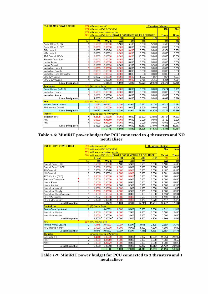
Table 1-6: MiniRIT power budget for PCU connected to 4 thrusters and NO
neutraliser
Table 1-7: MiniRIT power budget for PCU connected to 2 thrusters and 1
neutraliser
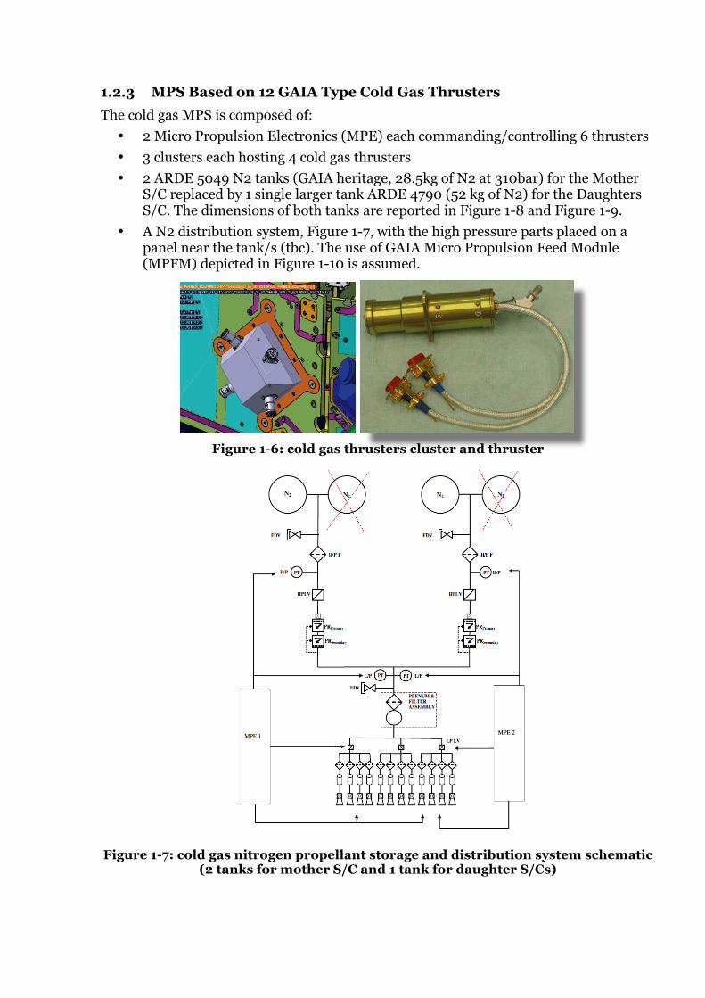
1.2.3 MPS Based on 12 GAIA Type Cold Gas Thrusters
The cold gas MPS is composed of:
• 2 Micro Propulsion Electronics (MPE) each commanding/controlling 6 thrusters • 3 clusters each hosting 4 cold gas thrusters
• 2 ARDE 5049 N2 tanks (GAIA heritage, 28.5kg of N2 at 310bar) for the Mother S/C replaced by 1 single larger tank ARDE 4790 (52 kg of N2) for the Daughters S/C. The dimensions of both tanks are reported in Figure 1-8 and Figure 1-9.
• A N2 distribution system, Figure 1-7, with the high pressure parts placed on a panel near the tank/s (tbc). The use of GAIA Micro Propulsion Feed Module (MPFM) depicted in Figure 1-10 is assumed.
!""#$%&'()#$*)*$+*,#! -../0#1'2"*)#!"*3%2#4526*
"#$%%&7
'()*+$'()*+$,-*./01*,-*./01* 2',3$2',3$)+45(6.*70(+4)+45(6.*70(+4
MT cross section CAD view
MT series arranged fluidic components
MT couple (nominal+ redundant) accommodated on the L shaped mechanical support
MT EQM model assembled for the qualification Campaign vs. GAIA requirements
Figure 1-6: cold gas thrusters cluster and thruster
Figure 1-7: cold gas nitrogen propellant storage and distribution system schematic
(2 tanks for mother S/C and 1 tank for daughter S/Cs)

Figure 1-8: N2 tank (two of this type of tanks are needed for the mother S/C)
Figure 1-9: N2 tank (large tank for daughter S/C)

Figure 1-10: Micro Propulsion Feed Module
The cold gas MPS wet mass budget is reported in Table 1-9 and Table 1-10 respectively for the Mother S/C and the Daughters S/C; the minimal difference between the two figures is due to the tank mass and tanks number accounted for. The N2 total load has been computed considering a total impulse requirement based on the following assumptions:
• 5 years mission duration
• SI = 45 sec as measured during GAIA qualification for thrust <20µN
• Minimum thrust: 1µN as confirmed during GAIA qualification
• Thrust noise: same as FEEP (as confirmed during GAIA qualification, Figure 1-11)
• Number of thrusters operating: 12 (nominal), 8 (after one thruster failure)
• S/A size: 6m2 (assumed worst case)
• Cant angle: 25º(optimized with respect to FEEP baseline design)
• Solar radiation pressure net force per area: o Fn = 5.5 µN (A/m^2) o Fp = 0.56 µN (A/m^2) o 10% margin
The EuLISA cold gas Total Impulse requirement reported in Table 1-8 is the result of an attempt to reduce propellant mass and, consequently, the number of tanks to be accommodated in the Mother/Daughters S/C. The assumptions taken shall be confirmed during next EULISA detailed design phase.
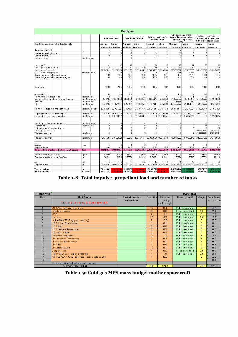
Table 1-8: Total impulse, propellant load and number of tanks
Table 1-9: Cold gas MPS mass budget mother spacecraft

Table 1-10: Cold gas MPS mass budget daughter spacecraft
Figure 1-11: cold gas noise measured by 2 different thrust balances during GAIA
qualification at 10µN
1.3 MPS Considerations and Recommendations All 3 MPS options could be baseline for EuLISA. Selection is detached from EuLISA CDF study, however the following considerations and recommendations can be made:
• FEEP is the MPS baseline for LISA Pathfinder. Qualification is expected to be resumed following completion of the Iacc reduction and ongoing re-design effort. In addition, thruster performance (SI, EOL Iacc, Expected max. Total Impulse/lifetime) shall be confirmed as outcome of the ongoing re-design phase and qualification. In addition, in the frame of EuLISA, further DFACS analysis is necessary to confirm worst-case thruster Total Impulse and need for tank redesign.
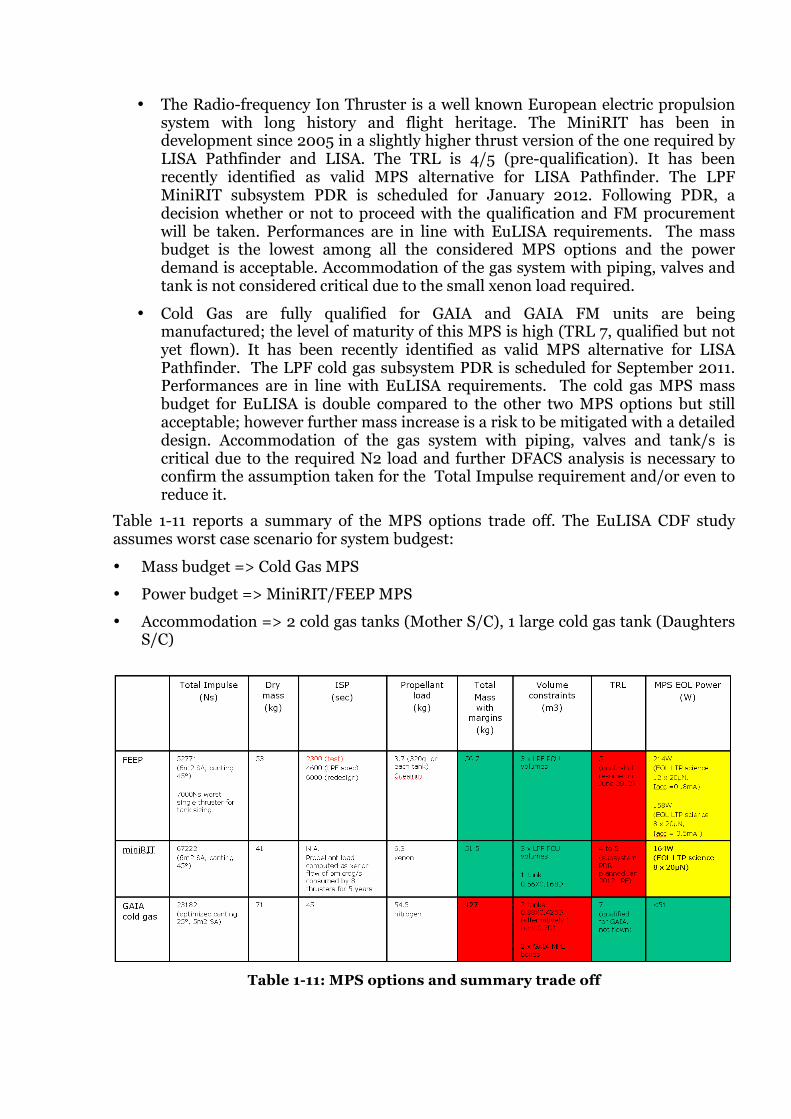
• The Radio-frequency Ion Thruster is a well known European electric propulsion system with long history and flight heritage. The MiniRIT has been in development since 2005 in a slightly higher thrust version of the one required by LISA Pathfinder and LISA. The TRL is 4/5 (pre-qualification). It has been recently identified as valid MPS alternative for LISA Pathfinder. The LPF MiniRIT subsystem PDR is scheduled for January 2012. Following PDR, a decision whether or not to proceed with the qualification and FM procurement will be taken. Performances are in line with EuLISA requirements. The mass budget is the lowest among all the considered MPS options and the power demand is acceptable. Accommodation of the gas system with piping, valves and tank is not considered critical due to the small xenon load required.
• Cold Gas are fully qualified for GAIA and GAIA FM units are being manufactured; the level of maturity of this MPS is high (TRL 7, qualified but not yet flown). It has been recently identified as valid MPS alternative for LISA Pathfinder. The LPF cold gas subsystem PDR is scheduled for September 2011. Performances are in line with EuLISA requirements. The cold gas MPS mass budget for EuLISA is double compared to the other two MPS options but still acceptable; however further mass increase is a risk to be mitigated with a detailed design. Accommodation of the gas system with piping, valves and tank/s is critical due to the required N2 load and further DFACS analysis is necessary to confirm the assumption taken for the Total Impulse requirement and/or even to reduce it.
Table 1-11 reports a summary of the MPS options trade off. The EuLISA CDF study assumes worst case scenario for system budgest:
• Mass budget => Cold Gas MPS
• Power budget => MiniRIT/FEEP MPS
• Accommodation => 2 cold gas tanks (Mother S/C), 1 large cold gas tank (Daughters S/C)
Table 1-11: MPS options and summary trade off

1.4 List of Equipment For each MPS option, the list of equipment has been reported in relevant paragraphs of this chapter.
1.5 Technology Requirements The following technologies are required or would be beneficial to this domain:
Included in this table are:
• Technologies to be (further) developed
• Technologies available within European non-space sector(s)
• Technologies identified as coming from outside ESA member states.
Equipment and Text
Reference
Technology Suppliers and TRL Level
Technology from Non-Space
Sectors
Additional Information
1.6 Acronyms Add your acronyms to the table provided below:
Acronym Definition
BB breadboard
DFACS Drag Free Attitude Control System
EBB Elegant Breadboard (TRL 4)
EM Engineering Model (TRL 4/5)
EP Electric Propulsion
FEEP Field Emission Electric Propulsion
F Filter
FCA FEEP Cluster Assembly
FDV Fill and Drain Valve
FR Flow Restrictor

HPT High Pressure Transducer
LV Latch Valve
LPF LISA Pathfinder
LPT Low Pressure Transducer
MiniRIT Miniaturised Radiofrequency Ion Thruster
RFG Radio-Frequency Generator
MPA Micro-Propulsion Assembly
MPS Micro-Propulsion Subsystem
NA Neutraliser Assembly
PCU Power Control Unit
PR Pressure Regulator
RCA MiniRIT Cluster Assembly
SI Specific Impulse
1.7 References RD[1] Requirements specification - FEEP Micro-propulsion subsystem,
S2.ASU.RS.2002 ISS07
RD[2] Cold Gas Micro-propulsion Implementation Study Phase 1: Technical feasability and design concept, S2.ASU.RP.2279 Iss1
RD[3] MiniRIT propulsion system for Lisa Pathfinder, S2-EST-TN-2051 Iss2.1
RD[4] Budget Analysis, S2.GAM.BR.2001, RevB