Crimson Thrusters
16
CRIMSON THRUSTERS T eam ID: 14042 An a nd I n st i t ut e of Hi gh er Techn ol og y Presentation by : • Gowri Shanker.K • Hariharan.B • Rahul Dharmarajan • Srinivasan E.R
Transcript of Crimson Thrusters
7/26/2019 Crimson Thrusters
http://slidepdf.com/reader/full/crimson-thrusters 1/16
CRIMSON THRUSTERS
Team ID: 14042
Anand Institute of Higher Technology
Presentation by :• Gowri Shanker.K• Hariharan.B• Rahul Dharmarajan• Srinivasan E.R
7/26/2019 Crimson Thrusters
http://slidepdf.com/reader/full/crimson-thrusters 2/16
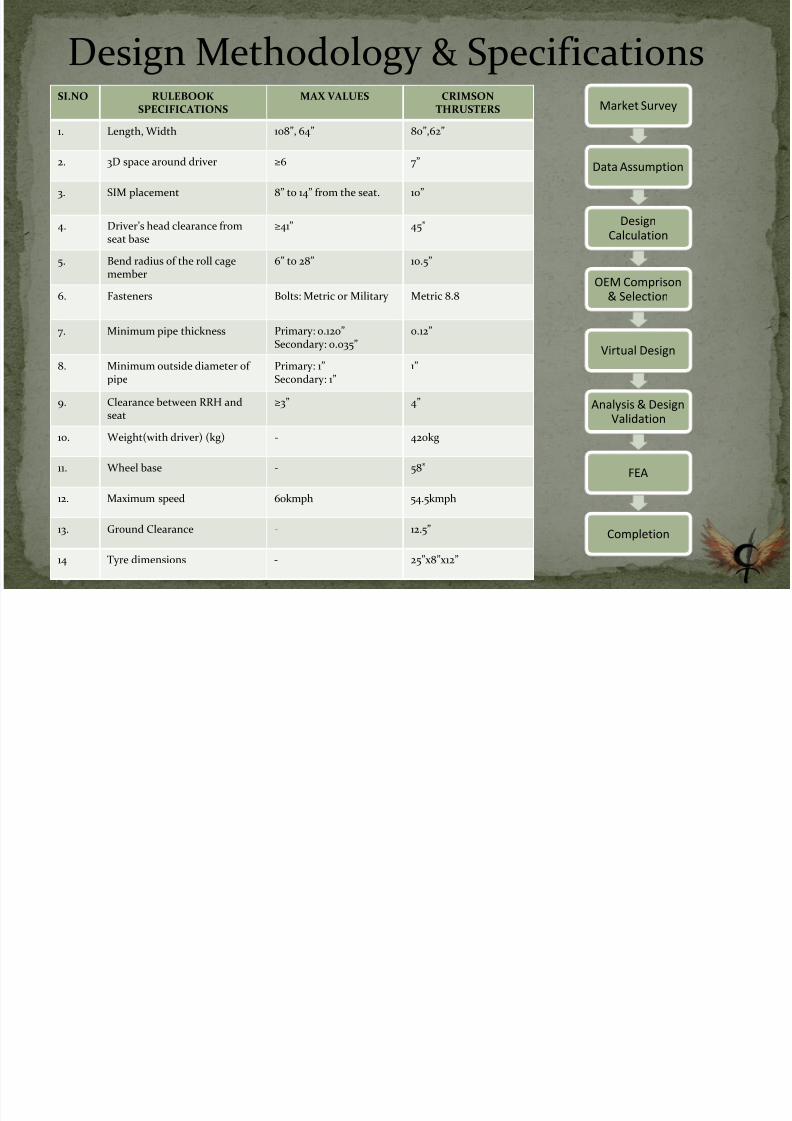
SI.NO RULEBOOKSPECIFICATIONS
MAX VALUES CRIMSONTHRUSTERS
1. Length, Width 108”, 64” 80”,62”
2. 3D space around driver ≥6 7”
3. SIM placement 8” to 14” from the seat. 10”
4. Driver’s head clearance fromseat base
≥41” 45”
5. Bend radius of the roll cage
member
6” to 28” 10.5”
6. Fasteners Bolts: Metric or Military Metric 8.8
7. Minimum pipe thickness Primary: 0.120” Secondary: 0.035”
0.12”
8. Minimum outside diameter ofpipe
Primary: 1” Secondary: 1”
1”
9. Clearance between RRH and
seat
≥3” 4”
10. Weight(with driver) (kg) - 420kg
11. Wheel base - 58”
12. Maximum speed 60kmph 54.5kmph
13. Ground Clearance - 12.5”
14 Tyre dimensions - 25”x8”x12”
Design Methodology & SpecificationsMarket Survey
Data Assumption
DesignCalculation
OEM Comprison& Selection
Virtual Design
Analysis & Design
Validation
FEA
Completion
7/26/2019 Crimson Thrusters
http://slidepdf.com/reader/full/crimson-thrusters 3/16
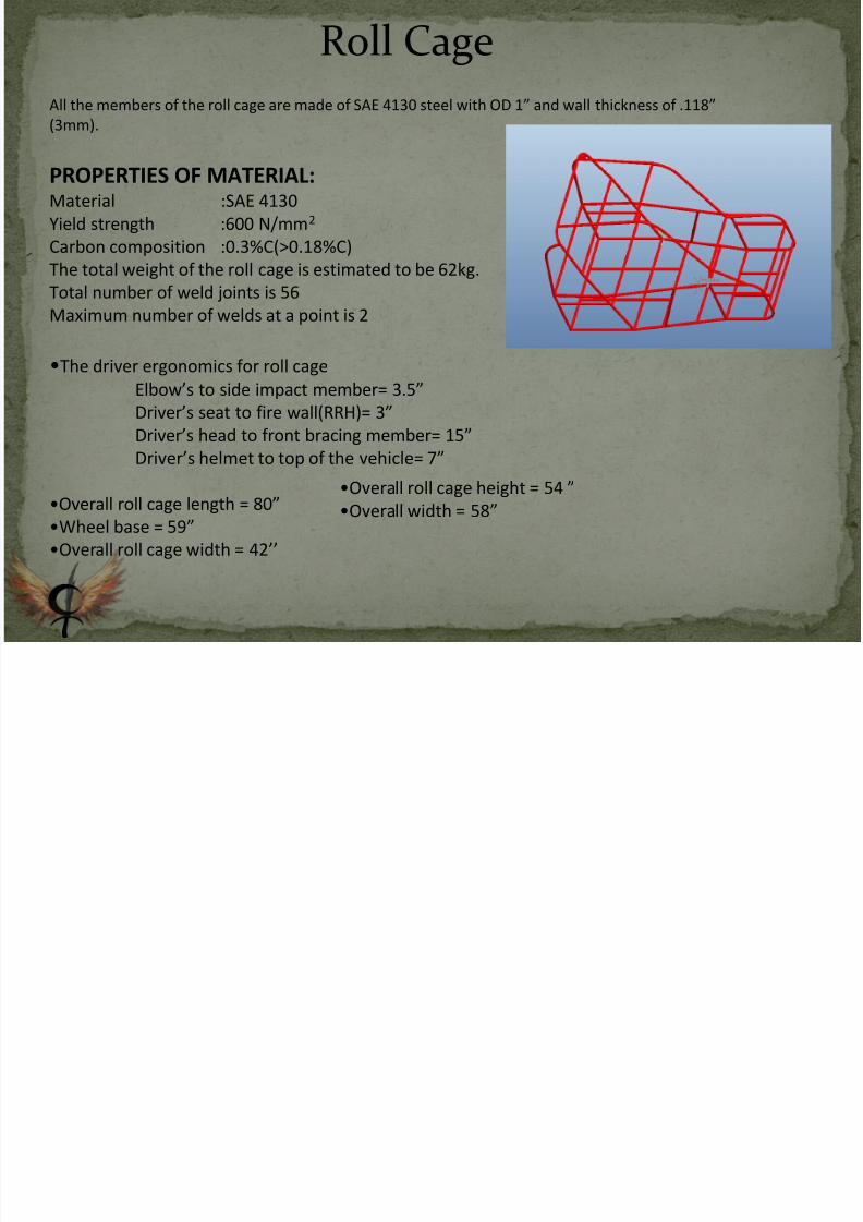
All the members of the roll cage are made of SAE 4130 steel with OD 1” and wall thickness of .118”
(3mm).
PROPERTIES OF MATERIAL:Material :SAE 4130
Yield strength :600 N/mm2
Carbon composition :0.3%C(>0.18%C)
The total weight of the roll cage is estimated to be 62kg.
Total number of weld joints is 56Maximum number of welds at a point is 2
•The driver ergonomics for roll cage
Elbow’s to side impact member= 3.5”
Driver’s seat to fire wall(RRH)= 3”
Driver’s head to front bracing member= 15”
Driver’s helmet to top of the vehicle= 7”
•Overall roll cage length = 80”
•Wheel base = 59”
•Overall roll cage width = 42’’
•Overall roll cage height = 54 ”
•Overall width = 58”
Roll Cage
7/26/2019 Crimson Thrusters
http://slidepdf.com/reader/full/crimson-thrusters 4/16
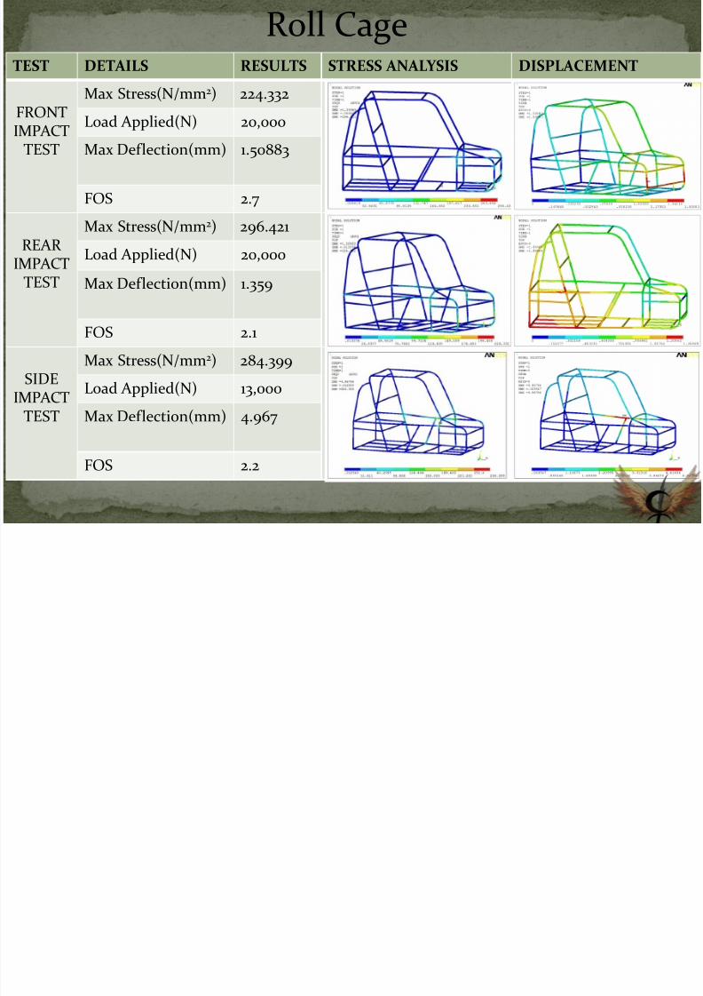
Roll CageTEST DETAILS RESULTS STRESS ANALYSIS DISPLACEMENT
FRONTIMPACT
TEST
Max Stress(N/mm2) 224.332
Load Applied(N) 20,000
Max Deflection(mm) 1.50883
FOS 2.7
REARIMPACT
TEST
Max Stress(N/mm2) 296.421
Load Applied(N) 20,000
Max Deflection(mm) 1.359
FOS 2.1
SIDEIMPACT
TEST
Max Stress(N/mm2
) 284.399Load Applied(N) 13,000
Max Deflection(mm) 4.967
FOS 2.2
7/26/2019 Crimson Thrusters
http://slidepdf.com/reader/full/crimson-thrusters 5/16
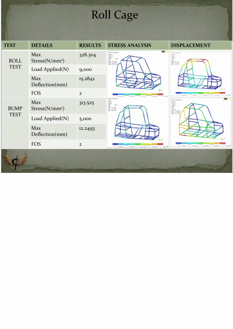
TEST DETAILS RESULTS STRESS ANALYSIS DISPLACEMENT
ROLLTEST
MaxStress(N/mm2)
328.304
Load Applied(N) 9,000
MaxDeflection(mm) 15.2842
FOS 2
BUMPTEST
MaxStress(N/mm2)
313.525
Load Applied(N) 5,000
MaxDeflection(mm)
12.2493
FOS 2
Roll Cage
7/26/2019 Crimson Thrusters
http://slidepdf.com/reader/full/crimson-thrusters 6/16
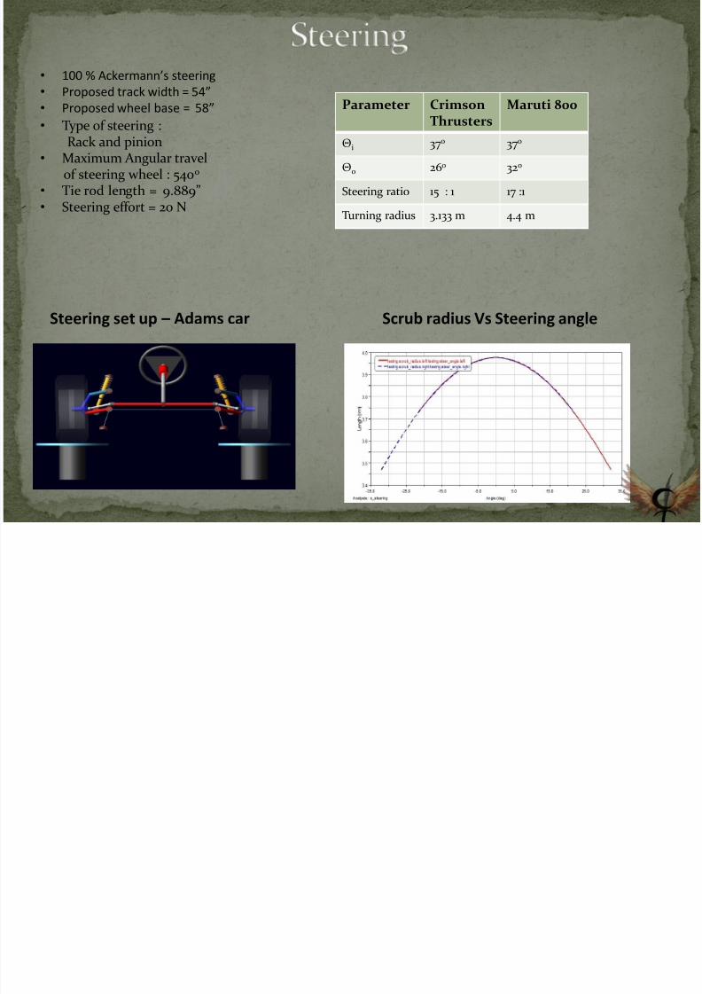
Parameter Crimson
Thrusters
Maruti 800
Θi 37o 37o
Θo 26o 32o
Steering ratio 15 : 1 17 :1
Turning radius 3.133 m 4.4 m
• 100 % Ackermann’s steering
• Proposed track width = 54”
• Proposed wheel base = 58”
Steering set up – Adams car
• Type of steering :Rack and pinion
• Maximum Angular travelof steering wheel : 540o
• Tie rod length = 9.889”• Steering effort = 20 N
Scrub radius Vs Steering angle
7/26/2019 Crimson Thrusters
http://slidepdf.com/reader/full/crimson-thrusters 7/16
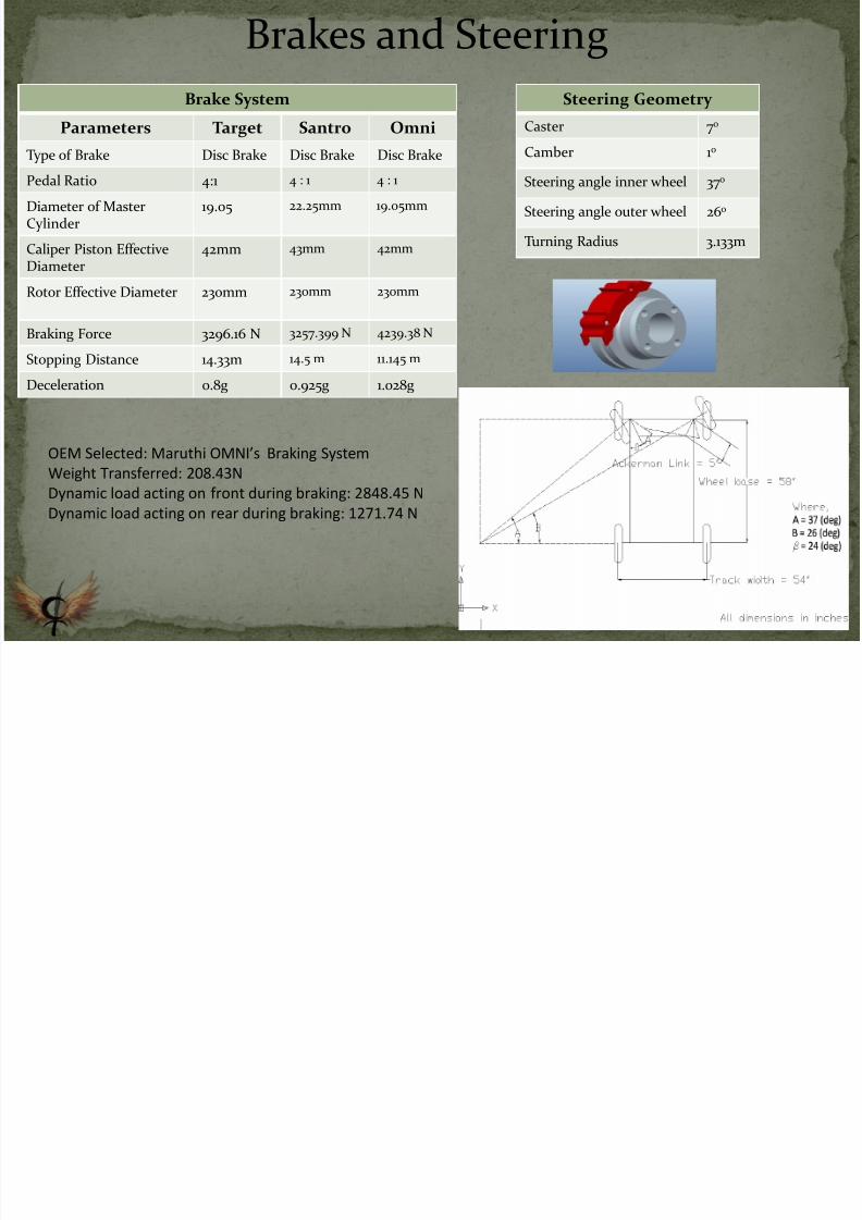
Brake System
Parameters Target Santro Omni
Type of Brake Disc Brake Disc Brake Disc Brake
Pedal Ratio 4:1 4 : 1 4 : 1
Diameter of MasterCylinder
19.05 22.25mm 19.05mm
Caliper Piston EffectiveDiameter
42mm 43mm 42mm
Rotor Effective Diameter 230mm 230mm 230mm
Braking Force 3296.16 N 3257.399 N 4239.38 N
Stopping Distance 14.33m 14.5 m 11.145 m
Deceleration 0.8g 0.925g 1.028g
OEM Selected: Maruthi OMNI’s Braking System Weight Transferred: 208.43N
Dynamic load acting on front during braking: 2848.45 N
Dynamic load acting on rear during braking: 1271.74 N
Brakes and Steering
Steering Geometry
Caster 7o
Camber 1o
Steering angle inner wheel 37o
Steering angle outer wheel 26o
Turning Radius 3.133m
7/26/2019 Crimson Thrusters
http://slidepdf.com/reader/full/crimson-thrusters 8/16
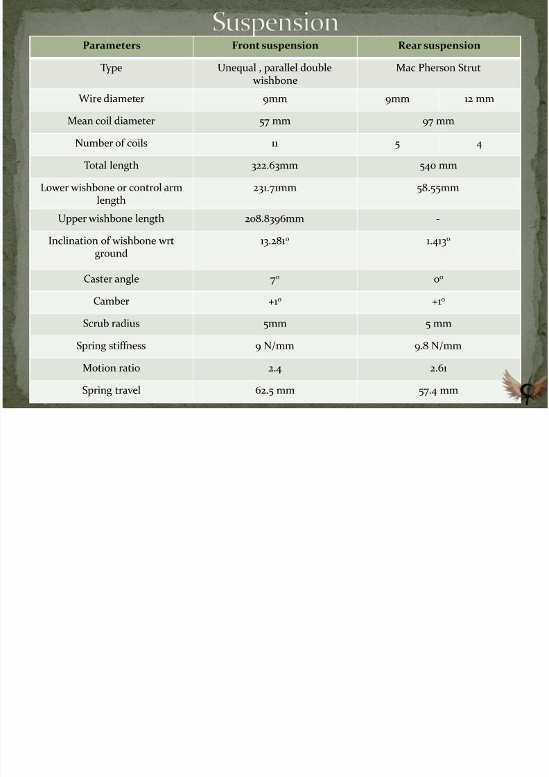
Parameters Front suspension Rear suspension
Type Unequal , parallel double wishbone
Mac Pherson Strut
Wire diameter 9mm 9mm 12 mm
Mean coil diameter 57 mm 97 mm
Number of coils 11 5 4
Total length 322.63mm 540 mm
Lower wishbone or control armlength 231.71mm 58.55mm
Upper wishbone length 208.8396mm -
Inclination of wishbone wrtground
13.281o 1.413o
Caster angle 7o 0o
Camber +1o +1o
Scrub radius 5mm 5 mm
Spring stiffness 9 N/mm 9.8 N/mm
Motion ratio 2.4 2.61
Spring travel 62.5 mm 57.4 mm
7/26/2019 Crimson Thrusters
http://slidepdf.com/reader/full/crimson-thrusters 9/16
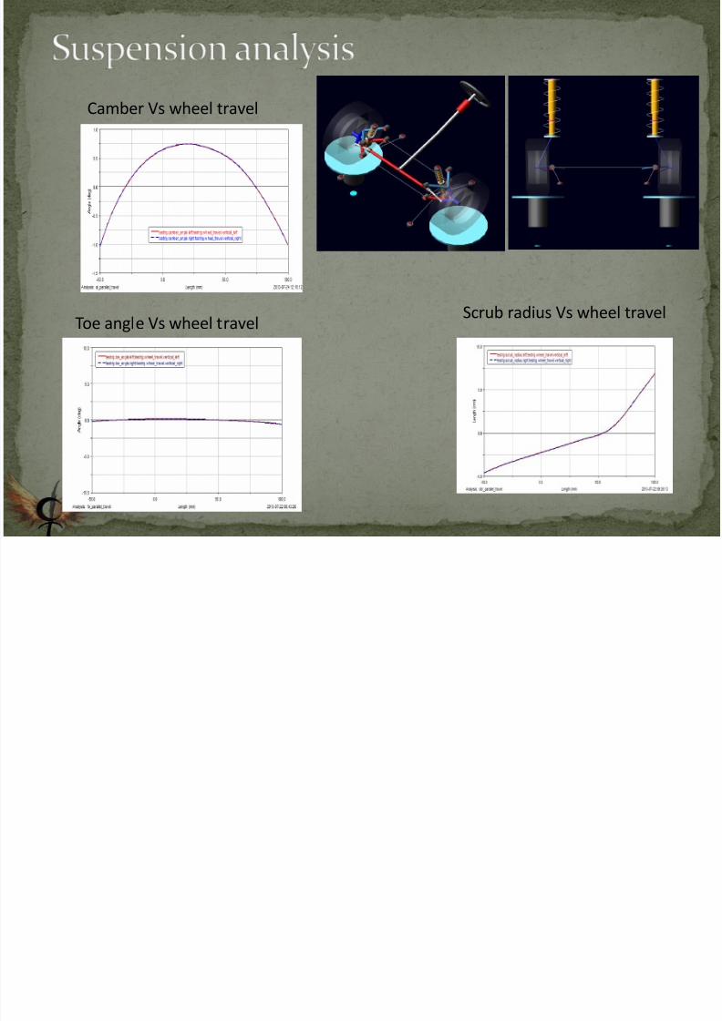
Camber Vs wheel travel
Scrub radius Vs wheel travelToe angle Vs wheel travel
7/26/2019 Crimson Thrusters
http://slidepdf.com/reader/full/crimson-thrusters 10/16
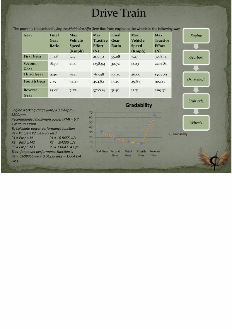
Drive TrainThe power is transmitted using the Mahindra Alfa Gear Box from engine to the wheels in the following way
Gear Final
GearRatio
Max
VehicleSpeed
(Kmph)
Max
TractiveEffort
(N)
Final
GearRatio
Max
VehicleSpeed
(Kmph)
Max
TractiveEffort
(N)
First Gear 31.48 12.7 2119.32 55.08 7.27 3708.14
Second
Gear
18.70 21.4 1258.94 32.72 12.23 2202.80
Third Gear 11.40 35.11 767.48 19.95 20.06 1343.09
Fourth Gear 7.35 54.45 494.82 13.40 29.87 902.13
Reverse
Gear
55.08 7.27 3708.14 31.48 12.71 2119.32
Engine
Gearbox
Drive shaft
Stub axle
Wheels
Engine working range ( ωM ) = 1750rpm-
3800rpm
Recommended maximum power (PM) = 6.7
KW at 3800rpm
To calculate power performance function
Pe = P1 ωe + P2 ωe2- P3 ωe3
P1 = PM/ ωM P1 = 16.8455 ω/s
P2 = PM/ ωM2 P2 = .04235 ω/s
P3 = PM/ ωM3 P3 = 1.064 E -4 ω/s
Therefor power performance function is
Pe = 1608455 ωe + 0.04235 ωe2 – 1.064 E-4
ωe3
7/26/2019 Crimson Thrusters
http://slidepdf.com/reader/full/crimson-thrusters 11/16
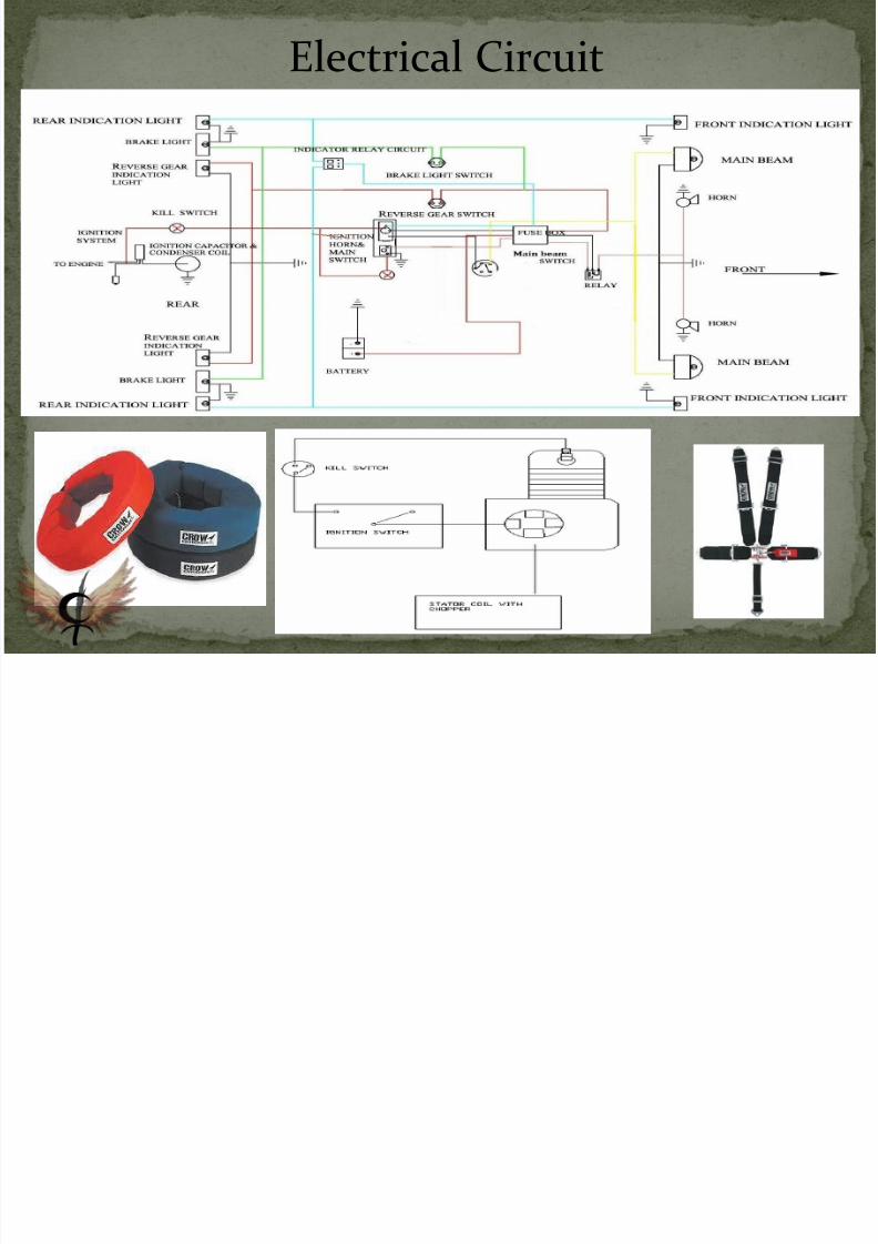
Electrical Circuit
7/26/2019 Crimson Thrusters
http://slidepdf.com/reader/full/crimson-thrusters 12/16
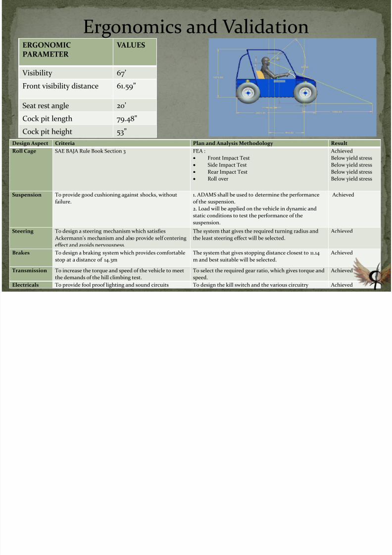
Ergonomics and ValidationERGONOMICPARAMETER
VALUES
Visibility 67’
Front visibility distance 61.59”
Seat rest angle 20’
Cock pit length 79.48”
Cock pit height 53”
Design Aspect Criteria Plan and Analysis Methodology Result
Roll Cage SAE BAJA Rule Book Section 3 FEA :
Front Impact Test
Side Impact Test
Rear Impact Test
Roll over
Achieved
Below yield stress
Below yield stress
Below yield stress
Below yield stress
Suspension To provide good cushioning against shocks, without
failure.
1. ADAMS shall be used to determine the performance
of the suspension.
2. Load will be applied on the vehicle in dynamic and
static conditions to test the performance of the
suspension.
Achieved
Steering To design a steering mechanism which satisfies
Ackermann’s mechanism and also provide self centering
effect and avoids nervousness.
The system that gives the required turning radius and
the least steering effect will be selected.
Achieved
Brakes To design a braking system which provides comfortable
stop at a distance of 14.3m
The system that gives stopping distance closest to 11.14
m and best suitable will be selected.
Achieved
Transmission To increase the torque and speed of the vehicle to meet
the demands of the hill climbing test.
To select the required gear ratio, which gives torque and
speed.
Achieved
Electricals To provide fool proof lighting and sound circuits To design the kill switch and the various circuitry Achieved
7/26/2019 Crimson Thrusters
http://slidepdf.com/reader/full/crimson-thrusters 13/16
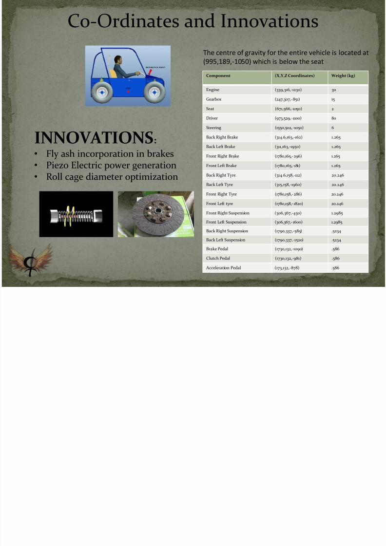
Component (X,Y,Z Coordinates) Weight (kg)
Engine (339,316,-1230) 30
Gearbox (247,307,-851) 15
Seat (671,566,-1050) 2
Driver (973,529,-1100) 80
Steering (1550,502,-1050) 6
Back Right Brake (314.6,163,-162) 1.265
Back Left Brake (311,163,-1950) 1.265
Front Right Brake (1780,165,-296) 1.265
Front Left Brake (1780,165,-181) 1.265
Back Right Tyre (314.6,158,-112) 20.246
Back Left Tyre (315,158,-1960) 20.246
Front Right Tyre (1780,158,-286) 20.246
Front Left tyre (1780,158,-1820) 20.246
Front Right Suspension (306,367,-430) 1.2985
Front Left Suspension (306,367,-1600) 1.2985
Back Right Suspension (1790,337,-585) .5234
Back Left Suspension (1790,337,-1520) .5234
Brake Pedal (1730,132,-1090) .586
Clutch Pedal (1730,132,-981) .586
Acceleration Pedal (173,132,-878) .586
The centre of gravity for the entire vehicle is located at
(995,189,-1050) which is below the seat
Co-Ordinates and Innovations
INNOVATIONS:
• Fly ash incorporation in brakes• Piezo Electric power generation• Roll cage diameter optimization
7/26/2019 Crimson Thrusters
http://slidepdf.com/reader/full/crimson-thrusters 14/16
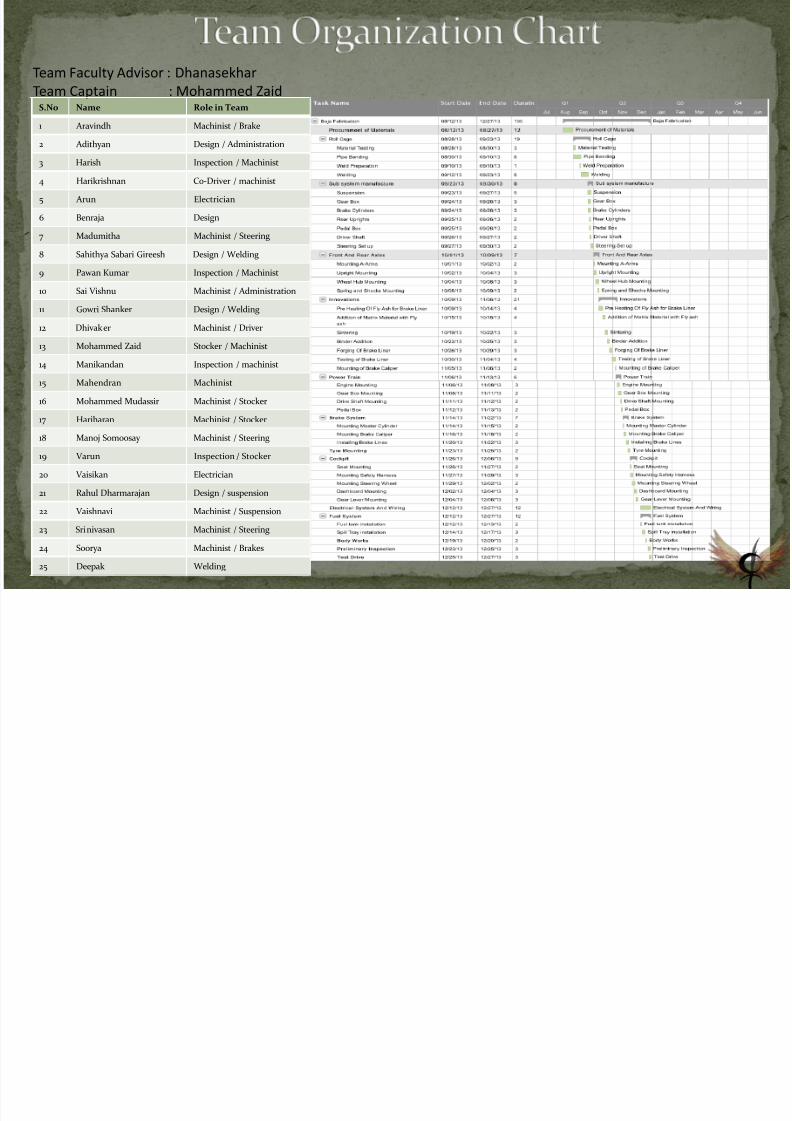
Team Faculty Advisor : Dhanasekhar
Team Captain : Mohammed ZaidS.No Name Role in Team
1 Aravindh Machinist / Brake
2 Adithyan Design / Administration
3 Harish Inspection / Machinist
4 Harikrishnan Co-Driver / machinist
5 Arun Electrician
6 Benraja Design
7 Madumitha Machinist / Steering
8 Sahithya Sabari Gireesh Design / Welding
9 Pawan Kumar Inspection / Machinist
10 Sai Vishnu Machinist / Administration
11 Gowri Shanker Design / Welding
12 Dhivaker Machinist / Driver
13 Mohammed Zaid Stocker / Machinist
14 Manikandan Inspection / machinist
15 Mahendran Machinist
16 Mohammed Mudassir Machinist / Stocker
17 Hariharan Machinist / Stocker
18 Manoj Somoosay Machinist / Steering
19 Varun Inspection / Stocker
20 Vaisikan Electrician
21 Rahul Dharmarajan Design / suspension
22 Vaishnavi Machinist / Suspension
23 Srinivasan Machinist / Steering
24 Soorya Machinist / Brakes
25 Deepak Welding
7/26/2019 Crimson Thrusters
http://slidepdf.com/reader/full/crimson-thrusters 15/16
7/26/2019 Crimson Thrusters
http://slidepdf.com/reader/full/crimson-thrusters 16/16