PIONEER STEAMSHIPS IN QUEENSLAND WATERS. - University of Queensland

ACCV2002: The5thAsianConferenceonComputerVision,23–25 January 2002, Melbourne,Australia 1
Non-Metric Augmented Reality by Virtual Camera Method under Affine Projection Model�
YongduekSeo Ki SangHongIIP Lab. PohangUniversityof Science& Technology(POSTECH)
AbstractAn algorithm is developed for augmenting a real
video/scene with virtual graphicsobjectswithoutcomputingEuclidean information. For this,wedesigna methodof spec-ifying the virtual camera which performsEuclidean ortho-graphic projection in recovered affine space. In addition,our methodhasthecapability of generating viewsof objectsshadedby virtual light sources,which wasunavailablepre-viously. Our novel formulation andexperimentalresultsarepresented.
1 Intr oduction
Making views of a 3D graphic model according to the mo-tion of cameraandmixing themwith a real scenevideo inreal time have beenthe major subjectof augmentedreality[2]. Thevirtual objectsaregenerally3D graphicsmodelsandtheir renderedviews by graphics machinesareoverlayedonreal-videoframes.Applications includeimage-guidedor as-sistedsurgery or its training [3, 9], assembly, maintenanceandrepair[28, 26], simulatinglight conditions of anoutdoorbuilding [6], virtual studio systemsfor commercial/publicbroadcasting[18], etc. Thesesystemsenrich reality withcomputer-generatedviews,cooperatingwith computervisiontechniques:estimatingthecameraparameters [22], resolvingocclusionbetweena virtual objectanda real object[5, 10],andcorrectingtheregisteredlocationof a graphic objectdy-namically [3]. An extensive survey can be found in [17].Among the techniques, cameracalibration hasbeena pre-requisitefor embedding virtual objects into videoframesbe-causethegeometricrelationshipamongphysicalobjects,vir-tualobjectsandthecameraneedsbeestablishedtogetcorrectresults.
On the other hand, therehave beena lot of researcheson non-metric vision applications: visual control or visualguided tasks [11, 29], navigation [4, 21], object recogni-tion [8], etc. In particular, developments in computer vi-sion technology have brought forth weakly-calibratedmeth-odsfor augmentingrealvideowith graphicsobjectswithoutEuclidean information [14, 7]. Especially, the orthographicprojection cameramodel and affine 3D representation to-getherwith world coordinatespecificationby user-interfacehave beenthe coreof Kutulakos andVallino’s first innova-tivework of theun-calibratedaugmentedrealitysystem[14].They successfullyaugmentedorthographicprojectionimageswith graphicsobjectsusingtheir realtimesystemwithoutex-�
Thiswork is supportedby KOSEFandBK-21.
plicit cameracalibration andEuclideanreconstruction.How-ever, thesystemhada limitation that it couldnot generateashadedview of graphics objectsnorspecifya lighting sourcebecausetheoriesandpackagesof computergraphicsarewrit-ten on the basisof Euclidean geometry. Indeed, this is oneof the critical reasonsthat previous augmentedreality sys-temshavereliedonthecalibrationof theircameras.Recently,Chenet. al. [7] proposedamethod, independentlyof thispa-per, for overlaying graphics on theimages.A cuboid, speci-fied througha user-interface,is utilized to connect realcam-era to computer graphics world. However, they only dealtwith a fixed (not moving) camera. In this paper, we extendthework of KutulakosandVallino [14], applying functionali-tiesof non-metriccomputervisionto theaugmentationof realvideowithoutgivingupthefundamentalfeaturesof computergraphics like lighting or shading.
Therearetwo kindsof orthographic cameras:affine cam-era and weak-perspective camera. The weak-perspectivecameraretainsthefeaturesof theEuclideanprojectionmodel;it consistsof rotation, translationandscaling. On the con-trary, the affine cameraassumesaffine geometry andaffineambientspace,which meansthat direct application of theaffine representation to Euclideancomputer graphics maycauseadeficiency.
We attacha virtual cameraof theweak-perspectivemodelto the real affine cameraso that the virtual cameramovesin the sameway as doesthe real camera. Our methodde-composesthe virtual camerainto Euclideanmotion compo-nentsandinternalcalibrationcomponents,which enablesusto makefull useof awell-developedcomputergraphicspack-ageandtosynthesizegraphicsobjectsthatareshadedandcol-oredby a lighting source. Thispaperis anextensionournon-metric AR methodto orthographic cameramodel. Detailson Implementationandexperimentsfor perspective cameramodelcanbefound in [24].
Section2 provides somenotations and preliminaries ofcameramodels andabrief review of affinestructurefrommo-tion algorithm. Section3 presentsa shortdescriptionof ouralgorithm. Section4 illustrateshow thevirtual world coordi-natesystemis embeddedinto therecoveredaffinespace.Alsoit gives themethodof computing a weak-perspective virtualcameraby specifying four basispoints in two control images.Section5 shows how a correspondingvirtual camerais com-puted,givena videoimage,andgraphicsviews arerenderedusinganSGI graphicsmachine . Section6 illustratesourex-perimental results.Finally, concluding remarks aregiven inSection7.
2 Preliminaries
Every vector is denotedby a column vector. We representan imagepoint by ����� ��� � T and a 3D point by � �� ��������������� . A 3D point � projectsto theimagepoint � :� � ������� �!���#"%$&"'�#" � (1)� (*)�+ ,, )'-/. ( � ,0,1,, � ,1,�. (�2 34 T5 � . � � (2)
where 2 �6� 798!7 � 7 5 � T, 7 T: being ; -th row vector, and 3 �� < + ��< - ��<�=>� T denote thetransformationfrom theworld coor-dinatesystemto the camera coordinatesystem.Notice that� is representedin the world coordinatesystem.Thus, wehave thefollowing [16]:
Definition 1 A weakperspectivecamera ?A@CB is definedbyaDFEHGmatrix asfollows:
? @!B � (*)�+ ,, )'-/. ( 7 T8 < +7 T� < -�. (3)� (*I T8 <KJ+I T� <KJ- . (4)� LNM 8 M � M 5 M "�OP (5)
Noticethat M : is the ; -th columnof ? @!B , and I T8 � )�+ 7 T8 andI T� � )'- 7 T� satisfytheorthogonality constraint:I 8RQ I � � , � (6)
where Q represents theoperation of the innerproduct. Equa-tion (1) cannow besimplywrittenas �S� ?T@CB � � where�is representedin theworld coordinatesystem.
2.1 Affine Structur e fr om Motion
Affine camera model is a generalization of the weak-perspectivecameramodelandmaybedefinedasfollows[16].
Definition 2 An affinecamera is definedby a generalDUE�G
matrix of rank2 anddenoted by ?WV .
Replacing� ����� with anon-singularD/EXD
matrixand $ witha matrix of general 3D affine transformationin equations(1)and(2), we obtain thegeneral form of theaffinecamera? V .
Sincethe recovery of affine structureand motion is notmain topic of this paper, here we briefly introduce affinestructurefrom motionalgorithms. It is well known thatgivenpoint matchesfrom two orthographicor scaledorthographicviews, affine structure of a scenecanbe found [13]. Affineepipolar geometry hasbeenstudied[25] andaffine structureand motion can be obtained through factorization methods[27, 23]. Details can also be found in various literatures[15, 19, 20, 12, 1]. Let ussupposethatwehavepoint matchesfrom input imagesandlet �ZY : bethe ; -th pointof [ -th image.Thenfrom thetheory of affinestructurefrom motion, wecanestimatethe [ -th affine cameramatrix ? V\ Y for eachof the
1. point tracking2. computing affine camera3. computing virtual camera
overlay
graphics Generation SGI Machine
digitizer
virtual camera
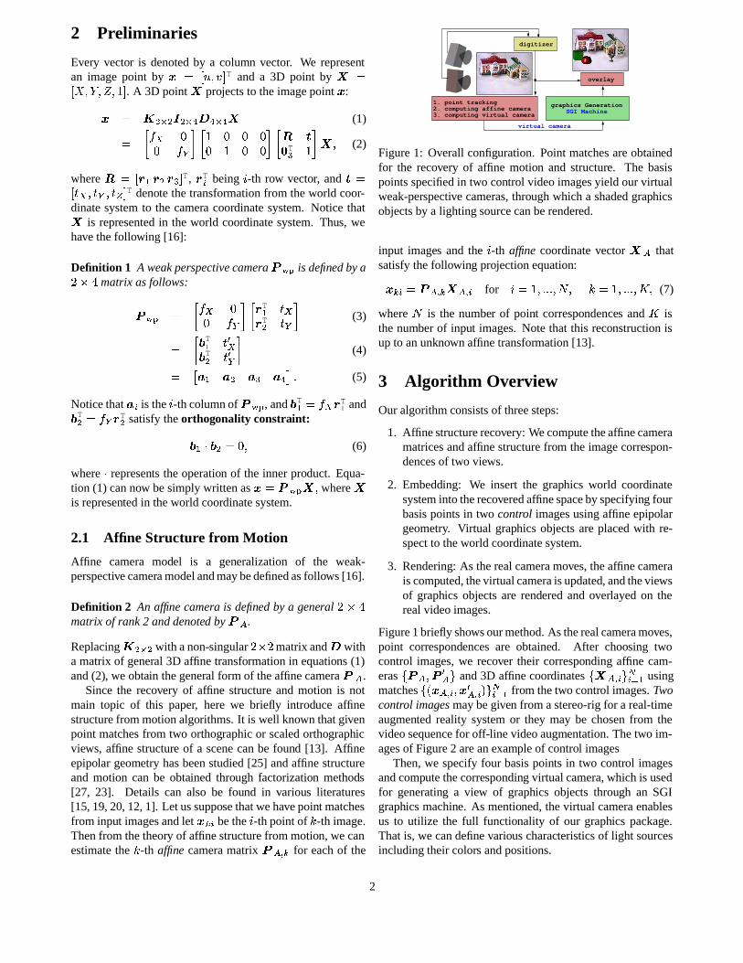
Figure1: Overall configuration. Pointmatchesareobtainedfor the recovery of affine motion and structure. The basispointsspecifiedin two control videoimagesyield ourvirtualweak-perspective cameras,throughwhich a shadedgraphicsobjectsby a lighting sourcecanberendered.
input images and the ; -th affine coordinatevector � V thatsatisfythefollowing projectionequation:� Y :� ?]V\ Y �^V\ : for ; �_�`� PaPbP ��cd� [ �_�`� PbPbP �fe�� (7)
where c is the number of point correspondences and e isthenumberof input images.Note that this reconstructionisup to anunknown affine transformation[13].
3 Algorithm Overview
Ouralgorithmconsistsof threesteps:
1. Affinestructurerecovery: Wecomputetheaffinecameramatricesandaffine structurefrom theimagecorrespon-dencesof two views.
2. Embedding: We insert the graphics world coordinatesysteminto therecoveredaffinespacebyspecifying fourbasispointsin two control imagesusingaffine epipolargeometry. Virtual graphics objectsareplacedwith re-spectto theworld coordinatesystem.
3. Rendering: As therealcameramoves,theaffinecamerais computed,thevirtualcameraisupdated, andtheviewsof graphics objectsare renderedandoverlayed on therealvideoimages.
Figure1brieflyshowsourmethod.As therealcameramoves,point correspondencesare obtained. After choosing twocontrol images,we recover their corresponding affine cam-eras g%? V � ? JV�h and3D affine coordinatesgi� V\ : hij:bk 8 usingmatchesgml � V\ : �f�/JV\ :on h%j:ak 8 from thetwo control images.Twocontrol imagesmaybegiven from astereo-rigfor a real-timeaugmented reality systemor they may be chosenfrom thevideosequencefor off-line videoaugmentation.Thetwo im-agesof Figure2 areanexampleof control images
Then,we specifyfour basispoints in two control imagesandcomputethecorresponding virtual camera,whichis usedfor generating a view of graphics objects through an SGIgraphics machine. As mentioned,thevirtual cameraenablesus to utilize the full functionality of our graphics package.Thatis, we candefinevariouscharacteristicsof light sourcesincludingtheir colors andpositions.
2
4 Embedding Algorithm
The first thing we have to do for augmentationis to definetheweak-perspectivevirtual cameraattachedto therealvideocameraby specifying somebasispointsof thegraphicsworldcoordinatesystem.Thissectionprovidesanimage-basedem-bedding method for insertingtheworld coordinatesystembyspecifying its p 8� basispoints in the first control imageandthreebasispoints in thesecond.Notethatin [14] they speci-fied four pointsin bothof thecontrolimagesusingonlyaffineepipolar constraint.
4.1 Embedding in the First Control Image
We first specify three imagelocations g �Rqrs���q 8 �f�tq� h of thebasispoints g�u r � u 8�� u � h in the first image. Specifically,u r �v� , � , � , ����� T is theorigin and u 8w�x�a�`� , � , ����� T, u � �� , � �`� , ����� T and u 5 �y� , � , � �`� �z� T arethreebasispointsonthe{ , | and } axes,respectively, of theworld coordinatesystem.Usingthenotationof Equation(5),eachcolumnM : of thevir-tualcamera ? @CB isgivenfromtherelationship �~qY � ? @!B u Yasfollows: M " � � qr � (8)M�� � � q��� � qr for � ��� � D P (9)
The third column, M 5 , is still left unknown. If an arbitraryimagepoint is given for u 5 , it will make our virtual cameraa general affinecameralike [14]. In order to forcethevirtualcamerato becomea weak-perspective camera,we utilize theorthogonality constraint of Equation (6). Now we usethenotationof Equation (4). Sincewe have determined Mw8 andM � , we maywrite I 8 and I � asI 8 �y� � 8f8 ��� 8 �'�f� 8 5�� T and I �X�y� �#� 8 ���#�f�'�f�m�f5�� T � (10)
where MtY : is the [ -th elementof M : . Thenfrom theorthogo-nality constraint, wehave, � I 8 Q I �X��� 8�8 �#� 8�� � 8 � �#��� � � 8 5 �#��5`� (11)
whichgivesaconstraintequation for theelementsof thethirdcolumn M 5���� � 8 5 ���#�f5�� T:�m�f5�� � ��8f8�� � 8 � ��8 � � �f��s8 5 P (12)
Since �tq5 � ? @!B u 5 � M 5 � �tqr , thecoordinatesof the lastimagepoint ��q5 �y� �!q5 ��mq5 � T mustsatisfythehyperbolic equa-tion q5 � qr � � 8f8 �#� 8�� � 8 ���#�f�� q 5 � � qr P (13)
Finally, we chooseanappropriatevalueof ��q5 on thehyper-bola andcompute ? @CB to completethe embedding stepforthefirst image:? @CB � L � q 8 � � qr � q � � � qr � q 5 � � qr � qr O P (14)
Figure2 showsanexampleof theresultof ourembeddingprocedure.TheFigure2(a)is thefirst imagewhere threeim-agelocationswerespecifiedasexplained.Thethreespecified
E 0
E 1
E 2
E 3
hyperbolic curve
E 0
E 1
E 2
E 3
l0
l3
l2
l1
hyperbolic curve
(a) (b)
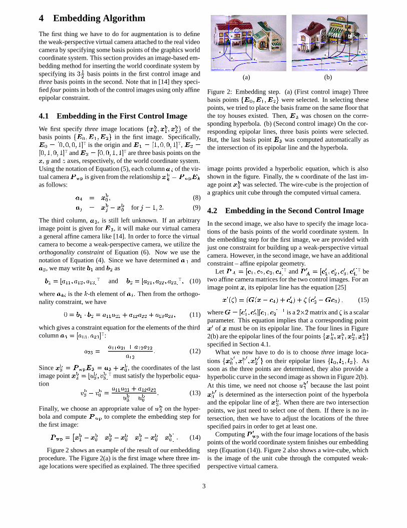
Figure2: Embedding step. (a) (First control image)Threebasispoints g�u r � u 8 � u � h wereselected.In selectingthesepoints,wetriedto placethebasisframeonthesamefloor thatthe toy housesexisted. Then, u 5 waschosenon the corre-sponding hyperbola. (b) (Secondcontrol image)On thecor-responding epipolar lines, threebasispoints were selected.But, the last basispoint u 5 wascomputed automatically astheintersectionof its epipolar line andthehyperbola.
imagepoints provided a hyperbolic equation, which is alsoshown in thefigure. Finally, the � coordinateof the last im-agepoint ��q5 wasselected.Thewire-cube is theprojection ofa graphics unit cubethroughthecomputedvirtual camera.
4.2 Embedding in the SecondControl Image
In thesecondimage,we alsohave to specifytheimageloca-tions of the basispointsof the world coordinatesystem. Intheembedding stepfor thefirst image,we areprovidedwithjust oneconstraintfor building up a weak-perspectivevirtualcamera.However, in thesecondimage,wehaveanadditionalconstraint– affineepipolar geometry.
Let ?]V ��� � 8 ���`�`���m5'�f�`"�� T and ? JV �x� �mJ8 �f�`J� ���`J5 ��� J" � T betwo affinecameramatricesfor thetwo control images.For animagepoint � , its epipolar line hastheequation [25]� J l�� n � lo�Wl � � �`" n � � J" n � ��l � J5 � � � 5 n � (15)
where� ��� �#J8 ���mJ� ��� � 8 ���m����� 8 isaD>E�D
matrixand� is ascalarparameter. This equationimplies thata corresponding point�/J of � mustbeon its epipolarline. Thefour linesin Figure2(b)aretheepipolarlinesof thefour points g ��qrs�f�tq 8 ���tq� �f�tq5 hspecifiedin Section4.1.
What we now have to do is to choose three imageloca-tions g �qr J ���tq 8 J ���tq� J h on their epipolar lines g � r � � 8�� � � h . Assoonasthe threepoints aredetermined,they alsoprovide ahyperboliccurvein thesecondimageasshown in Figure2(b).At this time, we neednot choose ��q5 J becausethe last point�tq5 J is determined asthe intersectionpoint of the hyperbolaandtheepipolar line of �~q5 . Whentherearetwo intersectionpoints,we just needto selectoneof them. If thereis no in-tersection,thenwe have to adjustthe locations of the threespecifiedpairsin order to getat leastone.
Computing ? J@CB with thefour imagelocationsof thebasispointsof theworld coordinatesystemfinishesourembeddingstep(Equation (14)). Figure2 alsoshowsawire-cube,whichis the imageof the unit cubethrough the computed weak-perspectivevirtual camera.
3
4.3 Affine Structur e for the Control Points
Wecompute theaffinecoordinatesg%� q : h 5:bk r of thefour pairsof the control points g#l � q : ��� q : J n h 5:bk r in order to enablethevirtual camera to move according to the motion of the realcamera.In otherwords,theaffinecoordinatesform animag-inary link betweentherealcameraandthevirtual camera.
Let � : betheselectedparameterof Equation(15)for the ; -th pair l � q : �f� q : J n . Then, corresponding 3D affine coordinates� q : �y� ��q: �f�wq: ���Zq: � �z� T aregiven asfollows:� q: � � : (16)L � q: � q: O T � � � 8~� � q : � � " � �/:��`5%� P (17)
The weak-perspective virtual cameraat an arbitrary time [will bedeterminedin Section5.1usingtheaffinecoordinatesg%� q : h 5:bk r .4.4 Virtual CameraDecomposition
To usethematrixof thevirtual camerain graphics rendering,we decomposeit into threeparts– � , 2 and 3 – asin equa-tions(1) and(2). We will usethenotationsof equations(3) -(5).
Thescalecomponents)#+ and ) - aregivenasfollows:
)�+ ��� I 8'� and ) - ��� I � ��� (18)
which determine thecalibration matrix � . Thenwe have anorthonormal pair7 8 � I 8�� ) + and 7!��� I � � ) - � (19)
whichdefinea rotation matrix 2 �_� 7 8 ��7C�`��7 8 E 7C�z� T. Whatis left is the translationvector 3 ��� < + ��< - ��<�=9� T. The firsttwo elements,< + and < - , of 3 aregivenby � � 8 M " but thelastelement<�= canbedetermined at our disposal. Notethatalgebraically speaking, a view through anorthographic cam-erahasnothing to dowith thedepthcomponent.However, ina physical situation,onestrict constraintis thatevery objectmustbein front of thecamera,andaccording to our cameramodel wechooseapositivedepth< = in practicesothateverygraphics objectlie in front of thevirtual camera.
Thecalibrationpart � will beutilizedin settingtheview-ing volumeof thevirtual camerain graphicsmachineandthemotionparts2 and 3 arefor modelview transformation.Thedetailsaregiven in Section5.2.
4.5 Projection by the Virtual Camera
During theprocedureof embedding, we specifybasispointsof theworld coordinatesystem.To facilitatethis procedure,we needto seetheresultsof our embedding. Givena virtualcamera? @!B we compute theimagelocations �Rq: � ? @CB u :of the verticesof the unit cubeandexamineour embeddingresult.An example (thewire-cube)is shown in Figure2.
4.6 PlacingGraphics Objects
The locationandposeof a 3D graphics objectsaredefinedwith respectto theworld coordinatesystemthat is now em-beddedin theaffine cameracoordinatesystem.In this way,thecharacteristicsof thegraphicsobjects,suchascolor, spec-ularity of surfaces,etc,canbedefinedby usualgraphicsmod-eling.Thelight sourcesarealsoconfiguredwith respectto theembeddedworld coordinatesystem.
5 Rendering Algorithm
Graphicsrendering for the [ -th video imageconsistsof twosteps:
1. Computationof the [ -th virtual camera.
2. Generationof a corresponding view of graphicsobjectsandoverlaying it on thevideoimage.
5.1 Transferring the Virtual Camera
As thevideocamera moves,its affinecameramatrixchangesand, accordingly, its virtual cameramust be computed ortransferred to the [ -th videoimage.Theprocedure is asfol-lows:
1. Find the imagematchesg � V\ Y : hij:bk 8 in the [ -th videoimage.
2. Computetheaffinecameramatrix ? V\ Y usingtheaffinere-projectionequation:� V\ Y : � ? V\ Y � V\ : � ; ��� � PbPaP ��c P (20)
Note that theaffine coordinates� V\ : werealreadyob-tained from two control imagesusing affine structurefrom motion algorithm.
3. Projectthe 3D affine coordinatesg%� q : h 5:bk r of the con-trol points into the [ -th imagethrough ? V\ Y :� q : � ? V\ Y � q : � ; � , � PbPaP � p P (21)
4. Computethevirtual camera? @CB'\ Y usingtheprojectiong �tq: h 5:bk r of thecontrol points (Equation (14)).
5. Decompose ?A@!B'\ Y into � Y , 2 Y and 3 Y as in Section4.4.
5.2 Graphics Rendering
Figure3 shows thethreestagesof coordinatetransformationin our SGI graphics machinefor making a view of graph-ics objectsthrough the virtual camera ?�@!B'\ Y . The rotation2 Y and translation 3 Y define the modeling transformationand � Y givesthe orthographic viewing volume. The mod-elview matrix � Y for modeling transformation is given as� Y ��(*2 Y 3 Y4 T5 � . , which convertsa 3D point �y� , defined
4
Modelview Matrix
Projection Matrix
x
XW
Perspective Division & ViewportTransformation image
XCXC−
Figure3: Stagesof coordinate transformationin a graphicsmachine.
(a) (b) (c) (d)
(e) (f) (g) (h)
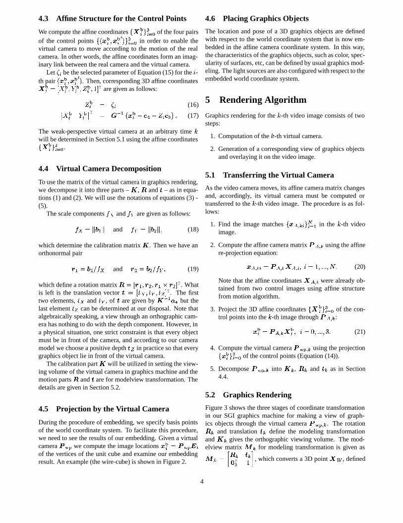
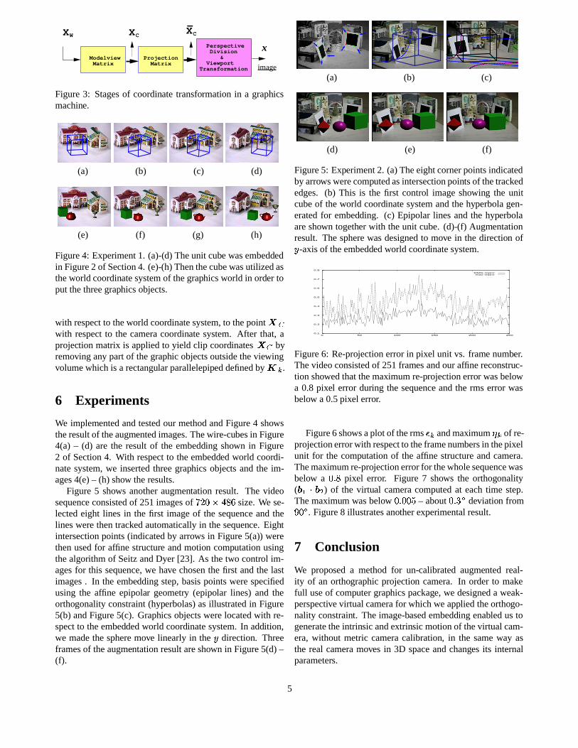
Figure4: Experiment1. (a)-(d) Theunit cube wasembeddedin Figure2 of Section4. (e)-(h) Thenthecubewasutilizedastheworld coordinatesystemof thegraphicsworld in order toput thethreegraphicsobjects.
with respectto theworld coordinatesystem,to thepoint ���with respectto the cameracoordinatesystem. After that, aprojection matrix is appliedto yield clip coordinates ��^� byremoving any partof thegraphic objectsoutsidetheviewingvolumewhich is a rectangular parallelepipeddefinedby � Y .6 Experiments
We implementedandtestedour methodandFigure4 showstheresultof theaugmentedimages.Thewire-cubesin Figure4(a) – (d) are the result of the embedding shown in Figure2 of Section4. With respectto theembeddedworld coordi-natesystem,we insertedthreegraphics objects andthe im-ages4(e)– (h) show theresults.
Figure5 shows anotheraugmentation result. The videosequence consistedof 251imagesof ¡ D , EAG ¢`£
size.We se-lectedeight lines in the first imageof the sequenceandthelineswerethentrackedautomaticallyin thesequence. Eightintersectionpoints(indicatedby arrows in Figure5(a)) werethenusedfor affine structure andmotion computationusingthealgorithm of SeitzandDyer [23]. As thetwo control im-agesfor this sequence,we have chosenthe first andthe lastimages. In the embeddingstep,basispointswerespecifiedusing the affine epipolar geometry (epipolar lines) and theorthogonalityconstraint(hyperbolas)asillustratedin Figure5(b) andFigure5(c). Graphics objectswerelocatedwith re-spectto theembeddedworld coordinatesystem.In addition,we madethespheremove linearly in the | direction. Threeframesof theaugmentationresultareshown in Figure5(d)–(f).
(a) (b) (c)
(d) (e) (f)
Figure5: Experiment2. (a)Theeightcornerpointsindicatedby arrowswerecomputedasintersectionpointsof thetrackededges. (b) This is the first control imageshowing the unitcubeof theworld coordinatesystemandthehyperbolagen-eratedfor embedding. (c) Epipolar lines andthe hyperbolaareshown together with theunit cube.(d)-(f) Augmentationresult. Thespherewasdesignedto move in the direction of| -axisof theembeddedworld coordinatesystem.
0.1
0.2
0.3
0.4
0.5
0.6
0.7
0.8
0 50 100 150 200 250
’RMS-repro’’max-repro’
Figure6: Re-projectionerrorin pixel unit vs. frame number.Thevideoconsistedof 251framesandouraffinereconstruc-tion showedthatthemaximumre-projectionerror wasbelowa 0.8 pixel error during the sequenceandthe rms error wasbelow a 0.5pixel error.
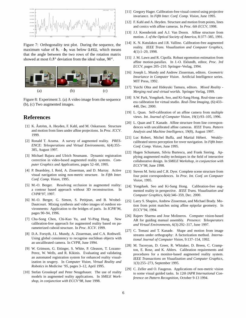
Figure6 showsaplot of therms ¤ Y andmaximum ¥ Y of re-projectionerrorwith respectto theframenumbersin thepixelunit for the computationof the affine structureandcamera.Themaximumre-projectionerrorfor thewholesequencewasbelow a , P ¢ pixel error. Figure 7 shows the orthogonality( I 8�Q I � ) of the virtual cameracomputed at eachtime step.Themaximum wasbelow , P ,`,m¦ – about , P p�§ deviation from¨ , § . Figure8 illustratesanotherexperimentalresult.
7 Conclusion
We proposed a methodfor un-calibratedaugmented real-ity of an orthographicprojection camera. In orderto makefull useof computergraphicspackage, we designeda weak-perspectivevirtual camerafor whichwe applied theorthogo-nality constraint. Theimage-basedembedding enabled ustogeneratetheintrinsicandextrinsicmotionof thevirtual cam-era,without metric cameracalibration, in the sameway asthe real cameramoves in 3D spaceandchanges its internalparameters.
5
-0.002
-0.001
0
0.001
0.002
0.003
0.004
0.005
0.006
0 50 100 150 200 250
’inn.out’
Figure7: Orthogonality testplot. During the sequence, themaximum valueof I 8©Q I � was below , P , , ¦ , which meansthat the angle betweenthe two rows of the rotationmatrixshowedat most , P p�§ deviation from theidealvalue,
¨ , § .
(a) (b) (c)
Figure8: Experiment3. (a)A videoimagefrom thesequence(b), (c) Two augmentedimages.
References[1] K. Astrom, A. Heyden, F. Kahl, andM. Oskarsson.Structure
andmotionfrom linesunder affineprojections. In Proc.ICCV.1999.
[2] RonaldT. Azuma. A survey of augmentedreality. PRES-ENCE: Teleoperations and Virtual Environments, 6(4):355–385,August 1997.
[3] Michael Bajuraand Ulrich Neumann. Dynamic registrationcorrectionin video-basedaugmented reality systems. Com-puterGraphicsandApplications, pages52–60, 1995.
[4] P. Beardsley, I. Reid, A. Zisserman,and D. Murray. Activevisual navigation using non-metricstructure. In Fifth Inter.Conf. Comp.Vision, 1995.
[5] M.-O. Berger. Resolving occlusion in augmentedreality:a contour basedapproachwithout 3D reconstruction. InCVPR’97, 1997.
[6] M.-O. Berger, G. Simon, S. Petitjean, and B. Wrobel-Dautcourt.Mixing synthesisandvideoimagesof outdoor en-vironments:Application to the bridgesof paris. In ICPR’96,pages90–94, 1996.
[7] Chu-SongChen, Chi-Kuo Yu, and Yi-Ping Hung. Newcalibration-freeapproach for augmented reality basedon pa-rameterizedcuboid structure.In Proc. ICCV. 1999.
[8] D.A. Forsyth,J.L. Mundy, A. Zisserman,andC.A. Rothwell.Using global consistency to recogniseeuclideanobjectswithanuncalibratedcamera.In CVPR, June1994.
[9] W. Grimson,G. Ettinger, S. White, P. Gleason,T. Lozano-Perez,W. Wells, and R. Kikinis. Evaluatingand validatingan automatedregistrationsystemfor enhancedreality visual-ization in srugery. In ComputerVision, Virtual Reality andRoboticsin Medicine’95, pages3–12, April 1995.
[10] Stefan Grosskopf and PeterNeugebauer. The useof realitymodelsin augmentedreality applications. In SMILE Work-shop,in conjunction with ECCV’98, June1998.
[11] GregoryHager. Calibration-freevisualcontrolusingprojectiveinvariance. In Fifth Inter. Conf. Comp.Vision, June1995.
[12] F. Kahl andA. Heyden.Structureandmotionfrom points,linesandconicswith affine cameras.In Proc.6th ECCV, 1998.
[13] J.J.Koenderink and A.J. Van Doorn. Affine structurefrommotion.J. of theOpticalSocietyof America, 8:377–385,1991.
[14] K. N. Kutulakos andJ.R.Vallino. Calibration-freeaugmentedreality. IEEE Trans. Visualizationand ComputerGraphics,4(1):1–20, 1998.
[15] J.M. Lawn andR. Cipolla. Robustegomotionestimationfromaffine motion-parallax. In J.-O. Eklundh, editor, Proc. 3rdECCV, pages205–210. Springer–Verlag,1994.
[16] JosephL. Mundy andAndrew Zisserman,editors. GeometricInvariance in ComputerVision. Artificial Intelligenceseries.MIT Press,1992.
[17] Yuichi Ohta andHideyuki Tamura,editors. Mixed Reality -Merging real andvirtual worlds. SpringerVerlag,1999.
[18] S.W. Park,Yongduek.Seo,andKi-SangHong.Real-timecam-eracalibrationfor virtual studio.Real-TimeImaging, (6):433–448, Dec.2000.
[19] L. Quan. Self-calibrationof an affine camerafrom multipleviews. Int. Journal of ComputerVision, 19(1):93–105,1996.
[20] L. QuanandT. Kanade.Affine structurefrom line correspon-denceswith uncalibratedaffine cameras.IEEE Trans.PatternAnalysisandMachineIntelligence, 19(8),August1997.
[21] Luc Robert, Michel Buffa, and Martial Hebert. Weakly-calibratedstereoperceptionfor rovernavigation.In Fifth Inter.Conf. Comp.Vision, June1995.
[22] HagenSchumann,Silviu Burtescu,and Frank Siering. Ap-plying augmentedreality techniques in thefield of interactivecollaborative design.In SMILEWorkshop, in conjunctionwithECCV’98, June1998.
[23] StevenM. SeitzandC.R.Dyer. Completescenestructurefromfour point correspondences.In Proc. Int. Conf. on ComputerVision,1995.
[24] Yongduek. Seo and Ki-Sang Hong. Calibration-freeaug-mentedreality in perspective. IEEE Trans.VisualizationandComputerGraphics, 6(4):346–359,Dec.2000.
[25] Larry S.Shapiro,Andrew Zisserman,andMichaelBrady. Mo-tion from point matchesusing affine epipolar geometry. InECCV’94, 1994.
[26] Rajeev SharmaandJoseMolineros. Computervision-basedAR for guiding manual assembly. Presence:TeleoperatorsandVirtual Environments, 6(3):292–317,June1997.
[27] C. Tomasi and T. Kanade. Shapeand motion from imagestreamsunderorthography: A factorizationmethod. Interna-tional Journal of ComputerVision, 9:137–154,1992.
[28] M. Tuceryan,D. Greer, R. Whitaker, D. Breen, C. Cramp-ton, E. Rose,and K. Ahlers. Calibration requirementsandprocedures for a monitor-basedaugmented reality system.IEEE Transactionson Visualizationand ComputerGraphics,1(3):255–273,September1995.
[29] C. Zeller andO. Faugeras.Applicationsof non-metricvisionto somevisualguidedtasks.In 12thIAPRInternationalCon-ferenceon PatternRecognition, October9-131994.
6