1 Chapter 0 Background and Preview This chapter describes the following topics: –The communication...
52
1 Chapter 0 Background and Preview This chapter describes the following topics: – The communication process – Primary communication resources : transmitted power & channel bandwidth – Sources of information – Circuit switching & Packet switching – Communication channels – The modulation process – Analog & digital communication systems – Shannon’s information capacity theorem
-
Upload
steven-palmer -
Category
Documents
-
view
221 -
download
0
Transcript of 1 Chapter 0 Background and Preview This chapter describes the following topics: –The communication...

1
Chapter 0Background and Preview
This chapter describes the following topics:– The communication process– Primary communication resources:
transmitted power & channel bandwidth
– Sources of information– Circuit switching & Packet switching– Communication channels– The modulation process– Analog & digital communication systems– Shannon’s information capacity theorem

2
Communication Process
1. Generation of a message signal
2. Making symbols for message signal by measure
3. Encoding of symbols
4. Transmission of the encoded symbols via channels
5. Decoding and reproduction of the original symbols
6. Re-creation of the original message signal which may be degraded by imperfections of channels
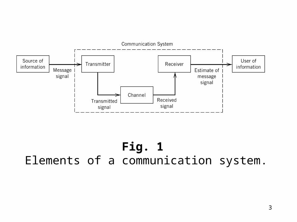
3
Fig. 1 Elements of a communication system.

4
• Basic elements of communication systems :– transmitter, channel, receiver– as shown in Fig. 1
• Two basic modes of communication:– broadcasting, eg. radio and TV– point to point, eg. telephone

5
Primary Communication Resources
• Two primary communication resources:– transmitted power & channel bandwidth
• Transmitted power – the average power of the transmitted signal
• Channel bandwidth (BW)– the band of frequencies allocated for the transmission
of the message signal
• Objective– To use these two resources as efficiently as possible.

6
• One resource may be considered more important than the other.
• Two types of channel:– power limited: satellite channel– band limited: telephone circuit
• Definition of signal bandwidth(BW)– The maximum frequency above which the spectral cont
ent of the signal is negligible– For example, voice spectrum of 300 to 3100 Hz gives g
ood articulation, in fact it extends beyond 10 KHz– Telephone circuit gives good transmission quality for si
gnal within the range of 0~4 KHz– BW can also be defined as the difference of Max. and
Min. frequencies of signals that are transmitted over a channel
7
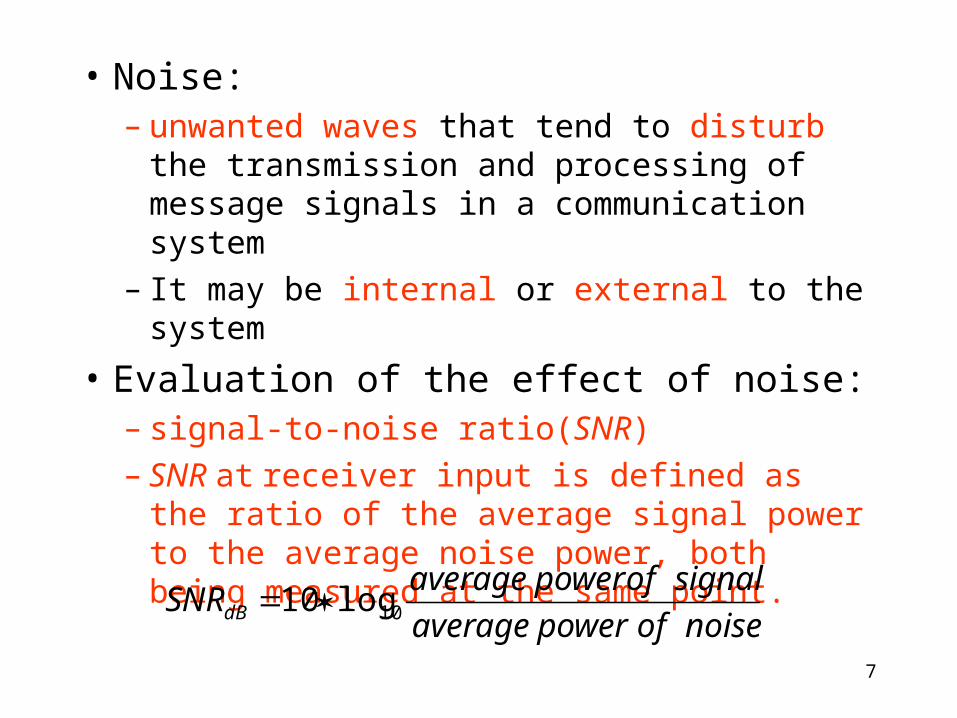
• Noise:– unwanted waves that tend to disturb the
transmission and processing of message signals in a communication system
– It may be internal or external to the system
• Evaluation of the effect of noise:– signal-to-noise ratio(SNR)– SNR at receiver input is defined as the ratio of
the average signal power to the average noise power, both being measured at the same point.
noiseofpoweraverage
signalofpoweraverageSNRdB
log10 10
8
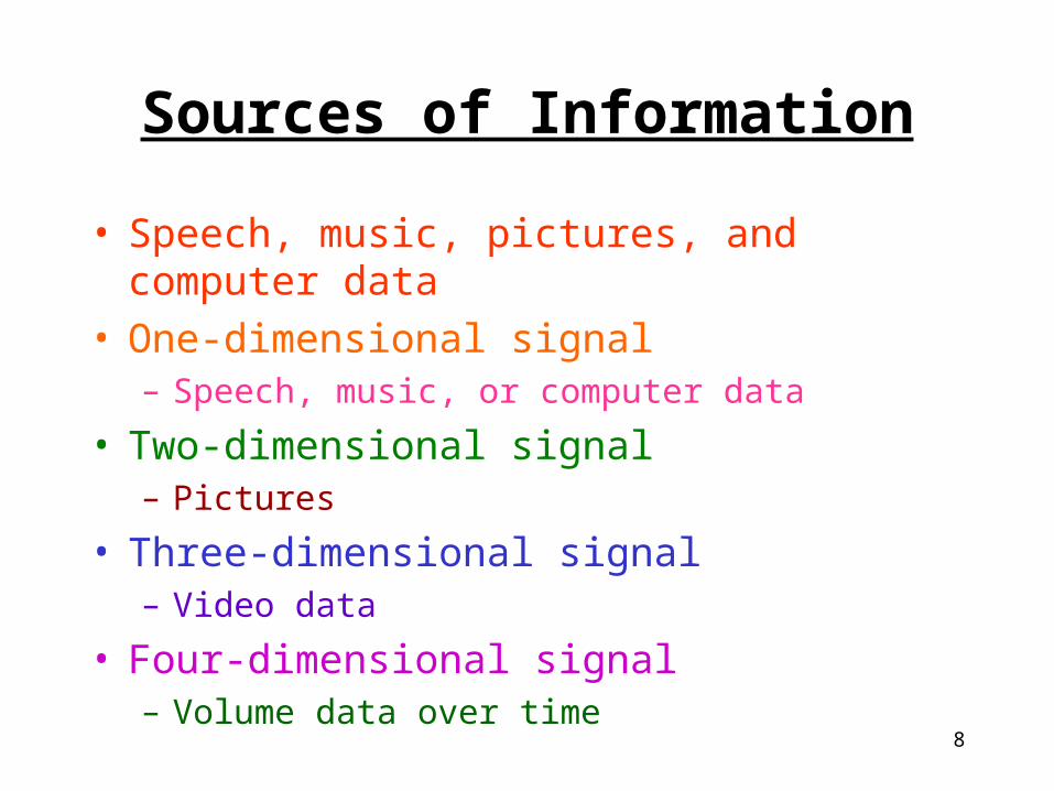
Sources of Information
• Speech, music, pictures, and computer data• One-dimensional signal
– Speech, music, or computer data
• Two-dimensional signal– Pictures
• Three-dimensional signal– Video data
• Four-dimensional signal– Volume data over time

9
Data Compression
• Data compression:– Provides a practical means for the efficient storage and
transmission of these kinds of data
– Encoder & Decoder
• Lossless compression– Lempel-Ziv algorithm for digital text compression
– Medical image, etc.
• Lossy compression– For internet application

10
Three compression standards
• (1) JPEG image coding standard(靜態影像壓縮標準 )– For full-color or grayscale images– Joint Photographic Experts Group– DCT, quantization, and Huffman coding are used (to be
discussed in Chapter 9)
• (2) MPEG-1/video coding standard (動態影像壓縮標準 )– Motion Photographic Experts Group– To compress video signals at 30 frames per second and
bit rates of 1.5 Mb/s

11
(2) MPEG-1/video coding standard(cont.)
• Basic principle:– Prediction is used to estimate each frame from its
neighbors of which do not change rapidly, thus the resulting prediction error is transmitted for motion estimation and compensation.
• Full-motion video and associated audio can be delivered over existing computer and telecommunication networks, which makes it possible to fulfill the need for video-on-demand (VOD) on the Internet.

12
(3) MPEG-1/audio coding standard
• Based on perceptual coding, a waveform-preserving process.
• Auditory masking results in masking threshold for audio compression
• ratio of 768 : 16 kb/s

13
MP3
• MPEG(Movie Picture Experts Group) 1 Layer 3

14
DVD VCD
Size 12cm 12cm
Compression Digital Mpeg II Digital Mpeg I
Languages option Yes No
Audio quality Very good Good
Storage capacity 4.7GB/8.5GB/9.4GB/17GB 0.65GB
Playback time 133/242/266/484 min. 74 min.
Vertical resolution 500 lines 240 lines
Max. channel 8 2
Recording mode Douby AC-3 -
PCM signal 48kHz/96kHz/16bit/24bit 44.1 kHz/16 bit
15
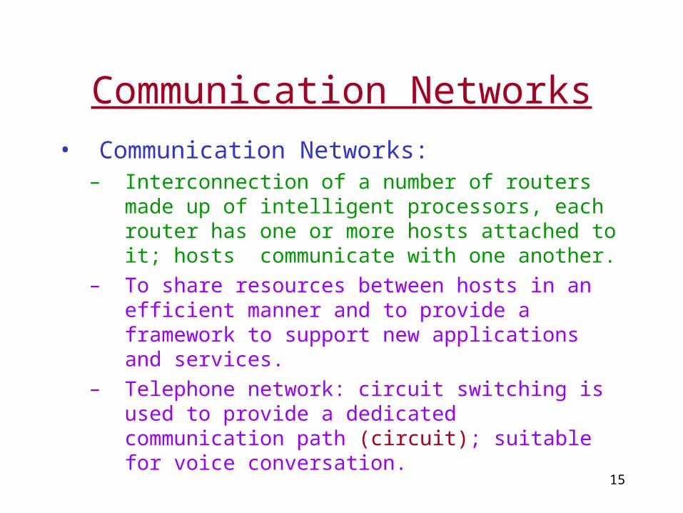
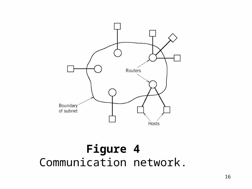
Communication Networks
• Communication Networks: – Interconnection of a number of routers made up of
intelligent processors, each router has one or more hosts attached to it; hosts communicate with one another.
– To share resources between hosts in an efficient manner and to provide a framework to support new applications and services.
– Telephone network: circuit switching is used to provide a dedicated communication path (circuit); suitable for voice conversation.
16
Figure 4Communication network.

17
Communication Networks(cont.)
• Circuit switching:– Communication link is shared between the different
sessions using that link on a fixed allocation basis.
• Packet switching: – The sharing is done on a demand basis.– The link may be fully utilized– Message is subdivided into specified size (packets)
prior to transmission. Packets transmitted during different sessions are reassembled at the destination on a packet-by-packet basis.
– It is far better suited to a computer-communication environment, however, careful control is required.

18
• Layered architecture– A hierarchy of nested layers.
• Layer– A process or device inside a computer system
designed to perform a specific function.
• Can be viewed as a “black box” that is described in terms of inputs, outputs, and the functional relation between outputs and inputs.
19
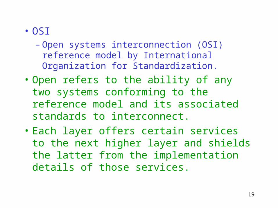
• OSI– Open systems interconnection (OSI) reference
model by International Organization for Standardization.
• Open refers to the ability of any two systems conforming to the reference model and its associated standards to interconnect.
• Each layer offers certain services to the next higher layer and shields the latter from the implementation details of those services.

20
OSI Reference Model
• Consists of seven layers with well-defined interfaces between each pair of layers.
• Interface– Defines the services offered by the lower to the
upper layer.
• Layer k of system A communicates with layer k of system B according to a set of rules and conventions (i.e., protocol) .

21
Figure 5OSI model; the acronym DLC in the middle of the figure stands for
data link control.

22
• Peer processes– The entities that comprise the corresponding la
yers on different systems.(peer to peer; eg. Layer 3 of A to layer 3 of B)
• Communication is achieved by having the peer processes in two different systems communicate via a protocol.
• Physical communication between peer processes exists only at layer 1.

23
• Layer2 through 7 are in virtual communication with their distant peers.
• Each of these six layers can exchange data and control information with its neighboring layers (below and above) through layer-to-layer interfaces.
• We are interested in the physical layer of the OSI reference model.

24
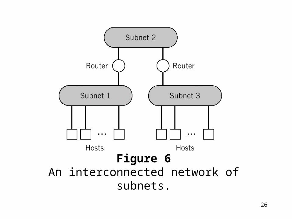
Internet
• Three functional blocks– Hosts, subnets, and routers
• Hosts– Constitute nodes of the network, where data
originate or where they are delivered.
• Routers– Constitute intermediate nodes that are used to
cross subnet boundaries.

25
• The exchange of data between the hosts and routers is accomplished by means of the Internet Protocol(IP).
• IP is a universal protocol that resides in the network layer (layer 3 in OSI ref. model), which define an addressing plan to transport data in the packet basis from node to node.
• Router make the decision how the addressed packets should be routed between subnetworks.
26
Figure 6An interconnected network of subnets.

27
Figure 7Illustrating the network architecture of the Internet.

28
Broadband Networks
• B-ISDN– Telephone network is evolving into Broadband
Integrated Services Digital Network for all-purpose applications.
– ATM (asynchronous transfer mode) is a protocol that makes these services possible.
• ATM– High-bandwidth, low-delay, packet-like
technique used for switching and multiplexing.

29
ATM(cont.)
• Independent of the physical means of transport.
• Low-delay for real-time services(eg. voice).
• High-bandwidth for video on demand.
• Allows transport of digital information in the form of small, fixed-size packets called cells(ATM cells).
30
ATM(cont.)
• No reassembly of cells is needed.
• Cell-switching in B-ISDN is a gigantic break with the circuit-switching in telephone network.
• Primary purpose:– Allocate network resources efficiently so as to
guarantee the expected QoS for each connection.

31
• Quality of Service – Cell loss ratio, cell delay, cell delay variation.
• ATM cells are structured for transport across the network.
• The cells in B-ISDN are placed on an optical transmission systems called synchronous optical network (SONET).
• SONET uses time-division multiplexing so that synchronous operation is needed.

32
SONET(美規 )
• T1=1.544 Mbps
• T3=24*T1=45 Mbps
• The following uses optical fiber
• OC3=3*T3=155 Mbps
• OC12=622 Mbps
• OC48=2.5 Gbps

33
SDH (歐規 )
• E1=2.048M=1.5*T1
• DS3=21*E1=45 Mbps
• STM-1=3*DS3=63*E1=155 Mbps
• STM-4=4*STM-1=622 Mbps
• STM-16=16*STM-1=2.5Gbps
• STM-64=64*STM-1=10 Gbps
34
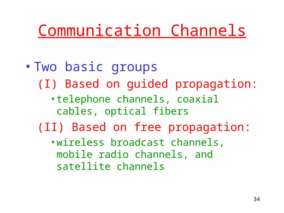
Communication Channels
• Two basic groups(I) Based on guided propagation:
• telephone channels, coaxial cables, optical fibers
(II) Based on free propagation:• wireless broadcast channels, mobile radio
channels, and satellite channels
35
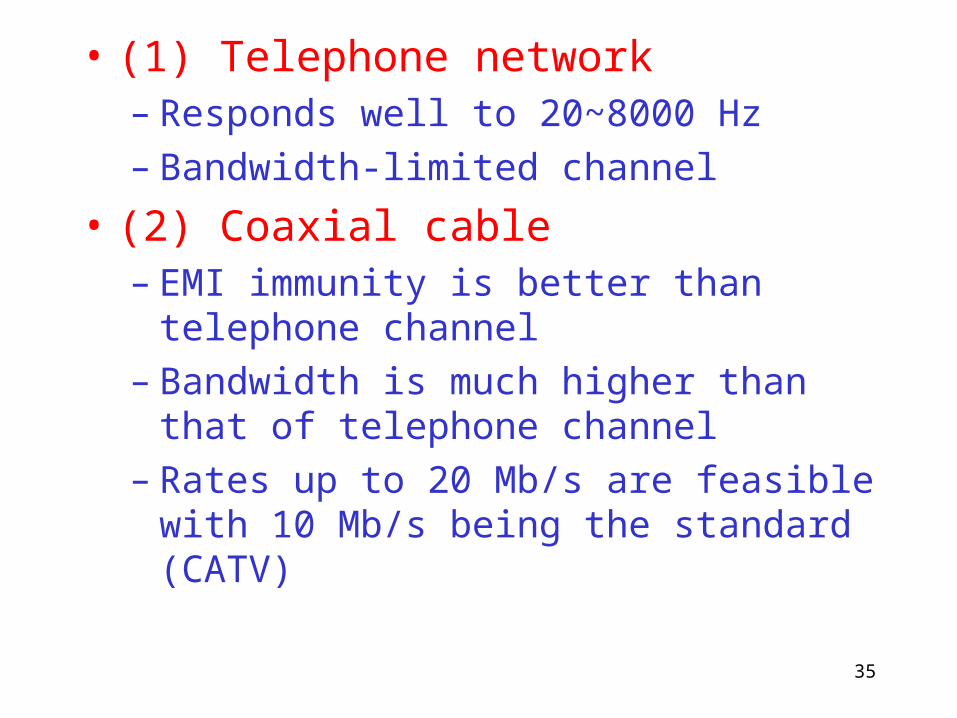
• (1) Telephone network– Responds well to 20~8000 Hz– Bandwidth-limited channel
• (2) Coaxial cable – EMI immunity is better than telephone channel– Bandwidth is much higher than that of
telephone channel – Rates up to 20 Mb/s are feasible with 10 Mb/s
being the standard (CATV)

36
• (3) Optical fiber:– Enormous potential bandwidth of Hz.– Low transmission losses up to 0.1 dB/km– Immunity to EMI– Small size and weight– Ruggedness and flexibility
• (4) Wireless broadcast channels– Transmission of Radio and TV signals– Modulation process is necessary
13102

37
• (5) mobile radio channel– Multipath phenomenon
– A linear time-varying channel in statistical sense
• (6) satellite channel– GEO(同步衛星 ), LEO(低軌道衛星 ), MEO(中低軌道衛星 )
– GEO/GSO (Geostationary Orbit or Geosynchronous Earth Orbit), track to the satellite is not necessary
– 6 GHz band for up link, 4 GHz band for downlink

38
• Geosynchronous satellite– At an altitude of 22,300 miles– The satellite is synchronous with the Earth’s
rotation.– The Earth station merely has to point its
antenna along a fixed direction toward the satellite.
– Offer the unique system capabilities of broad-area coverage, reliable transmission links, and wide transmission bandwidths.
39
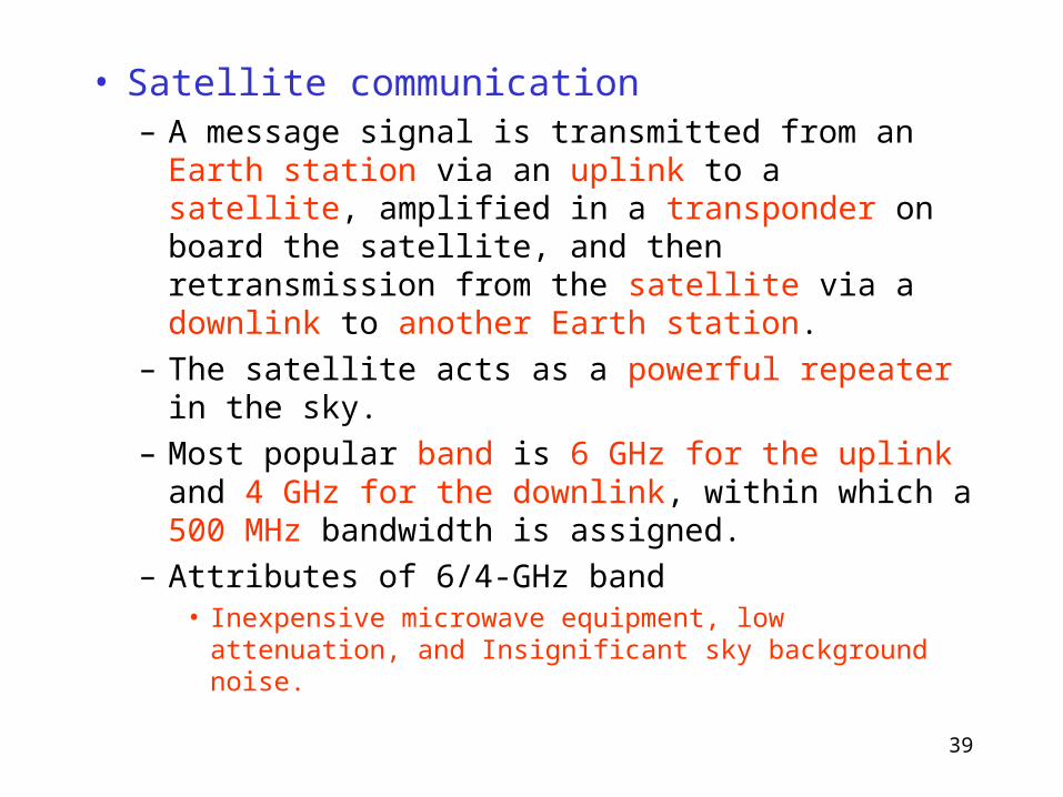
• Satellite communication– A message signal is transmitted from an Earth station
via an uplink to a satellite, amplified in a transponder on board the satellite, and then retransmission from the satellite via a downlink to another Earth station.
– The satellite acts as a powerful repeater in the sky.
– Most popular band is 6 GHz for the uplink and 4 GHz for the downlink, within which a 500 MHz bandwidth is assigned.
– Attributes of 6/4-GHz band• Inexpensive microwave equipment, low attenuation, and
Insignificant sky background noise.

40
Modulation Process
• Modulation– Transmitter modifies the message signal into a
form suitable for transmission over the channel.– a process involves varying some parameters of
a carrier wave according to the message signal.
• Due to the effects of channel noise or distortion, the received signal (degraded version) always can not be perfectly recreated by demodulation process.

41
– The resulting degradation in overall system performance is influenced by the type of modulation scheme used.
– Some modulation schemes are less sensitive to the effects of noise and distortion than others.
(1) Continuous wave modulation (CW)– AM, FM, PM
(2) Pulse modulation– Analog type:PAM, PDM, PPM– Digital type:PCM

42
• Multiplexing-– Results from the use of modulation– The process of combining several message
signals for their simultaneous transmission over the same channel
– FDM,TDM,CDM

43
Analog and Digital Types of Communication
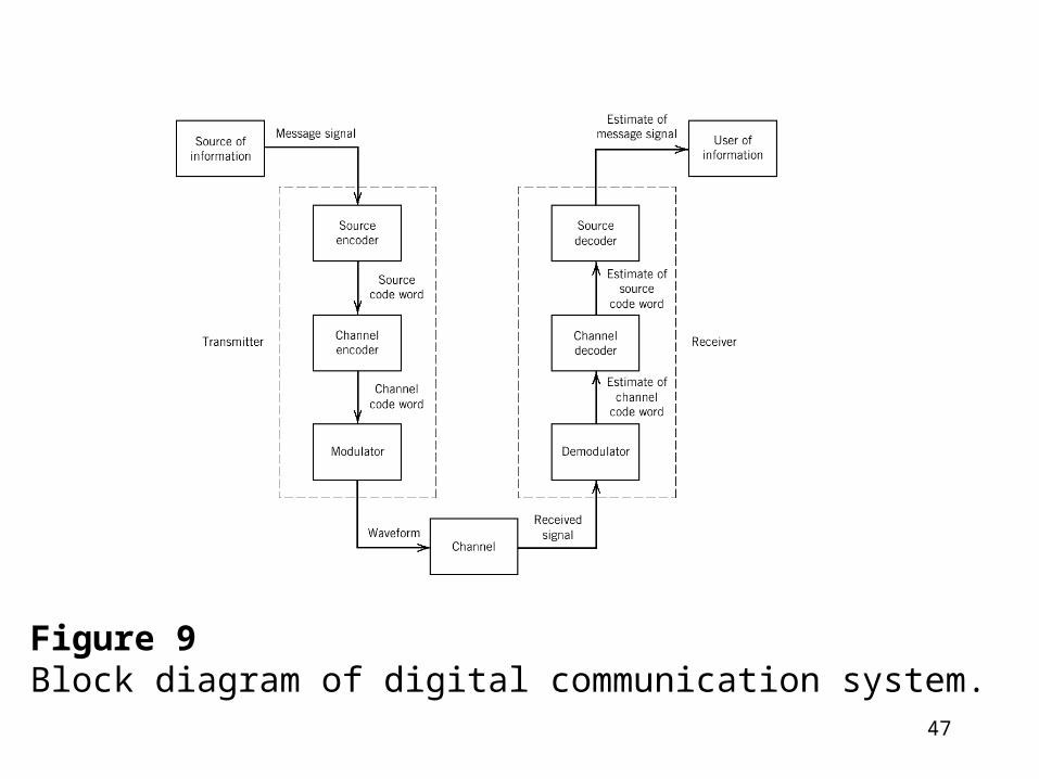
• Digital communication system (eg. Fig. 9)– Source encoder-decoder– Channel encoder-decoder– Modulator-demodulator
44
Digital Communication System (Cont.)
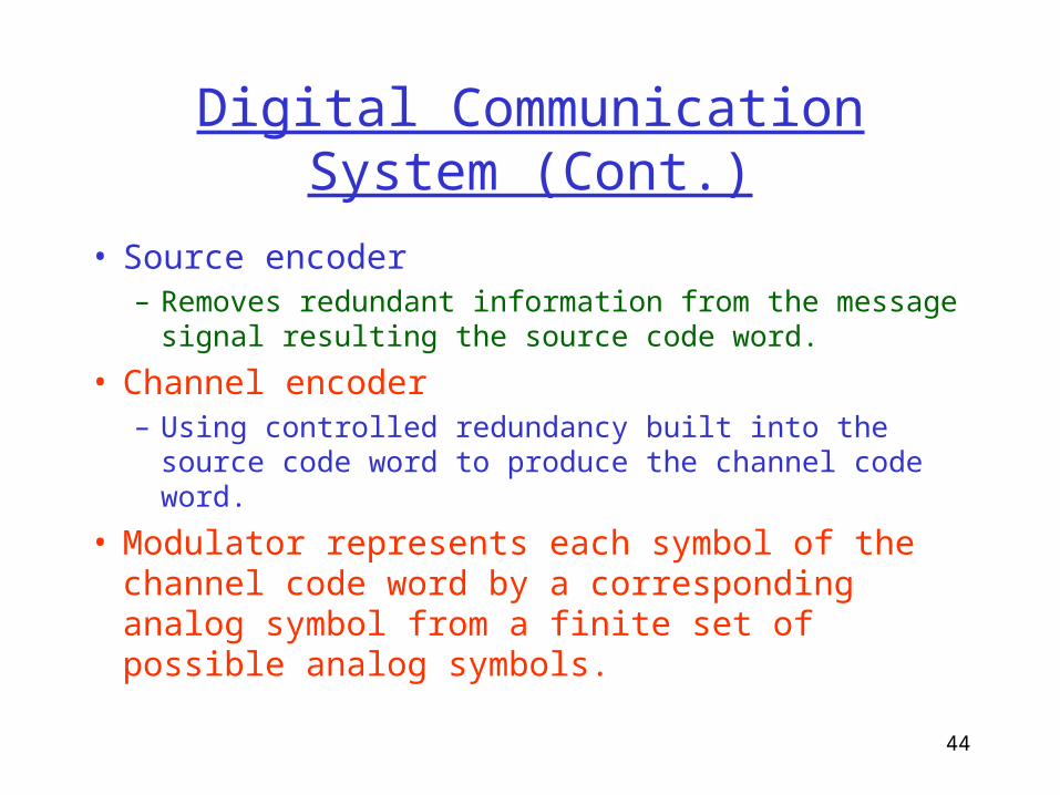
• Source encoder– Removes redundant information from the message
signal resulting the source code word.
• Channel encoder– Using controlled redundancy built into the source code
word to produce the channel code word.
• Modulator represents each symbol of the channel code word by a corresponding analog symbol from a finite set of possible analog symbols.

45
Digital Communication System (Cont.)
• The sequence of analog symbols produced by the modulator is called a (digital ) waveform, which is suitable for transmission over the channel.
• The receiver processes the received signal in reverse order to that in the transmitter in order to construct a recognizable version of the original message signal.

46
Digital Communication System (Cont.)
• The design of a digital communication system is rather complex in conceptual terms but easy to build.
• The system is more robust in many aspects than its analog counterpart.
• The use of digital communications provides the capability for information transmission that is both efficient and reliable.
47
Figure 9Block diagram of digital communication system.

48
Analog Communication System
• The design of an analog communication system is simple in conceptual terms but difficult to build because of stringent requirements on linearity and system adjustment.
• Why do we study analog system ?– To motivate other digital modulation schemes
– Analog approach provides high-speed or very low-power benefits.
49
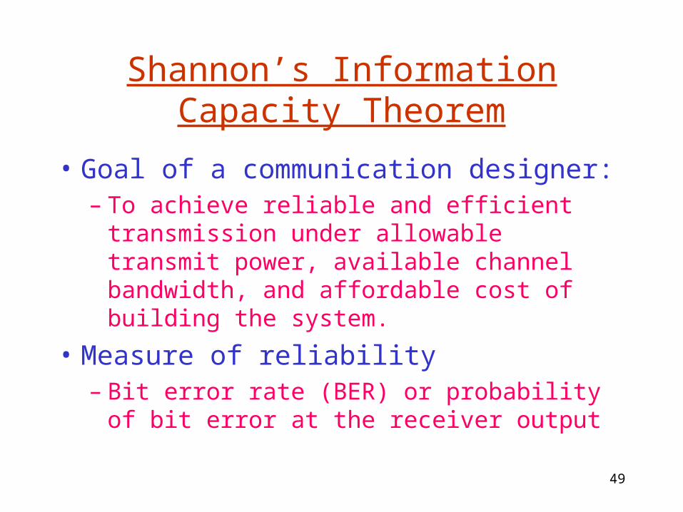
Shannon’s Information Capacity Theorem
• Goal of a communication designer:– To achieve reliable and efficient transmission
under allowable transmit power, available channel bandwidth, and affordable cost of building the system.
• Measure of reliability– Bit error rate (BER) or probability of bit error
at the receiver output

50
• Shannon’s Information Capacity Theorem
• C is the information capacity of the channel– defined as the maximum rate at which information
can be transmitted across the channel without error.
• An error-free transmission is possible even when the channel is noisy if the actual signaling rate R is less than C, for a prescribed channel bandwidth B and received SNR.
b/s )1(log2 SNRBC

51
• Shannon’s information capacity theorem does not tell us how to design the system.
• Usefulness of the theorem– Provide a bound of transmission rate
– Provide a basis for the trade-off between B and SNR
– Provides an idealized framework for comparing the noise performance of one modulation scheme against another.

52
The telephone line has a signal-to-noise (SNR) ratio of 25 dB and passes audio frequencies over the frequency range from 300 to 3200 Hz. Calculate the maximum data rate (in bps) that could be sent over the telephone line for the case of no errors at the receiving end.
Solution:
B = 3200-300 = 2,900 Hz,
bps
2.31610/ 10
25
NS
097,24)1(log2 N
SBR


![Chapter 3 Digital Transmission - York University19. Nyquist Law – max rate at which digital data can be transmitted over a. communication channel of bandwidth B [Hz] is • M –](https://static.fdocuments.net/doc/165x107/5e69c3ce99ed887f146472a4/chapter-3-digital-transmission-york-university-19-nyquist-law-a-max-rate-at.jpg)