1 Calorimeter Thermal Analysis Revision C November 23 2009.
42
1 Calorimeter Thermal Analysis Revision C November 23 2009
-
Upload
bethany-long -
Category
Documents
-
view
225 -
download
3
Transcript of 1 Calorimeter Thermal Analysis Revision C November 23 2009.

1
Calorimeter Thermal AnalysisRevision C
November 23 2009

2
Conductivity of Copper and Argon at 90°K
Rod, Copper
Liquid ArgonMatrix, Copper
Tube, Copper
Conductivity at 90°K,
W/mm-°K
Copper is 0.514
Liquid Argon is 0.00012
Geometry, mm
Center to center = 7.5
Matrix hole diameter is 5.851
Tube OD is 5.584
Tube ID is 5.081
Rod OD is 4.881
Gaps are filled with liquid Argon

3
Copper Matrix Finite Element Models
The baseline and refined 2D models of the copper matrix are shown.

4
Conduction ResultsKxx Kyy Kzz
W/mm/K W/mm/K W/mm/KBaseline mesh 0.1531 0.1525 0.4732Refined mesh 0.1522 0.1518 0.4732Hand Calculation - - 0.4979
Value Used 0.1520 0.1520 0.4979
Temperature solution for X, Y and Z gradients
Because conduction properties repeat after a 120° rotation about Z, we should find that Kxx = Kyy. The conduction used for these components is therefore the average of the values. The FEA Kyy was 0.26% larger than Kxx.
The hand calculation for Kzz is considered to be exact, the FEA is 5% lower.
Z is parallel to the rod axes

5
3D Model of Calorimeter
Al tube is modeled with shell elements. Its temperature is set to 90°K. It is eccentric.
1.95 mm gap on top
0.10 mm gap here (0.05 shown)
Copper Matrix
Copper Matrix
Tungsten Matrix
Argon
Copper
Note:
All “gaps” are filled with liquid Argon

6
Al Tube Eccentricity
Argon
Copper matrix
Structural analysis shows that the external aluminum tube wraps around the lower half of the calorimeter.
These elements are the same thickness

7
Aluminum Shell and Argon Elements
The aluminum shell, above, is wrapped around the OD. It is used as a convenient surface to fix at 90°K. Plate elements are used. They are being plotted here as a surface (no thickness).
Liquid argon is modeled with solid conduction elements as shown above.

8
Conductivities
Material Kxx Kyy Kzz
Cu Matrix 0.152 0.152 0.4979W Matrix 0.021 0.007 0.129Solid Copper 0.542 0.542 0.542Argon 0.0001315 0.0001315 0.0001315
W/mm/deg K
Y
X
Z

9
Deformation of the Aluminum Cylinder
• The minimum gap between the external aluminum cylinder and the modules is 0.1 mm, the thickness of the Kapton wrap (the Kapton wrap has about the same conductivity as liquid argon so it is not explicitly modeled).
• The deformation of the aluminum cylinder is predicted using a rigid cylinder to represent the modules and contact elements between the rigid cylinder and the aluminum cylinder (contact elements prevent the aluminum shell from penetrating the rigid cylinder but allow a gap to open between the two).

10
Clearance Between Modules and Cylinder
Radial Interference vs Angle, Various Stations
-0.100
-0.080
-0.060
-0.040
-0.020
0.000
0.020
0.00 20.00 40.00 60.00 80.00 100.00 120.00 140.00 160.00 180.00 200.00
Angle, deg
Inte
rfer
ence
, in
ches
Z=0.512
Z=1.841"
z=3.71
z=10.035
z=27.254
Rigid Body
The cylinder deforms to be closer to the modules over the region extending to 52° from the bottom.
Above 100° the cylinder deforms to move further from the modules than would be the case with a rigid eccentric cylinder.
The net effect on the thermal solution is an increase in conduction between the modules and the aluminum cylinder compared to results for an argon filled gap between two rigid eccentric cylinders.
The end of the cylinder is at Z=0 The midpoint is at Z=27.254”

11
Deformation of the Aluminum Cylinder, mm
Nodal forces indicating contact
Rigid Contact Surface (the modules)
The aluminum cylinder with end plates

12
Heat Generation Rate, W/mm3
Heat flux is higher in the gray zone ranging up to 1.12E-6 W/mm3

13
Thermal Solution, Peak temperature is 0.1°K above the OD
The temperature of the OD (the aluminum tube) is 90°K
14
Convection in the Outer 12 mm Thick Argon Blanket

15
Argon Material Properties, kg-m-sec-°K
Property Units Dimension Value
Conductivity W/(m-deg K) kg-m/(deg K-sec^3) 0.1315Heat Capacity J/(kg-deg K) m^2/(deg K-sec^2) 1078Density kg/m^3 kg/m^3 1393Volumetric thermal expansion 1/deg K 1/deg K 0.0044Dynamic Viscosity kg/(m-sec) kg/(m-sec) 0.00026
derived quantities
Heat flux W/m^2 kg/sec^3Heat flow W kg-m^2/sec^3Force N kg-m/sec^2Pressure Pa kg/(m-sec^2)
Numeric values for Ansys density input:
dens = Nominal + C2*(T- C1) = Nominal(1-CTEvol*(T-Tref))
= 1393-1393*.0044*(T-Tref) = 1393-6.1292*(T-Tref)

16
Simple Conduction (Stagnant Fluid)
Delta T = 1 degree KDepth of model = 1 mHalf circumference = 1.42 mArea = 1.42 m^2Layer thickness = 0.012 mK = 0.1315 W/(m-deg K)
Q = 15.5 W
Radiation (black body)Stephan Boltzman = 5.67E-08 W/(m -̂deg K^4)T inner 91 deg KTouter 90 deg KQ = 0.24 W
Radiant heat transfer is low and has not been included in the CFD model.

17
CFD Analysis
• Most results are from a 2D CFD analysis
– 3D results for the outer annulus gave only slightly higher net convection.
• All results of interest are in the transitional regime between laminar and turbulent flow– Laminar flow result gives velocities high enough to justify turning the
turbulent flow option* on.
– Turbulent results give velocities too low to justify the use of the turbulence option.
• Laminar flow results were used for thermal analysis (conservative; the convection coefficient, H .. W/m2/°K, is 42% greater when turbulence is switched on)
* Turning the turbulent flow option on triggers a turbulent energy calculation in the boundary layer that gives increased viscosity and heat transfer.

18
CFD Analysis Results, Outer Annulus
Velocity vector plots above and below. Temperatures plotted at left and at bottom
These plots show the aspect ratio of the outer annulus. Flow details can only be seen in local blowups.

19
Flow Patterns at the Top and Bottom
• At the top, convective cells form as would be expected for a fluid layer heated from below.
• At the bottom, convective cells are not apparent but the fluid is stirred by the cool argon flowing down the OD.
• The images on the following slides show these patterns

20
Flow Pattern at the Top, 0.5 and 2° K Differential
2°K Differential
0.5°K Differential

21
Flow Pattern at the Bottom, 0.5° K Differential, Turbulent flag on and off
0.5°K Differential Laminar Flow (contour values are not the same as below)
0.5°K Differential Turbulent Flow is turned on, results are similar to those above
22
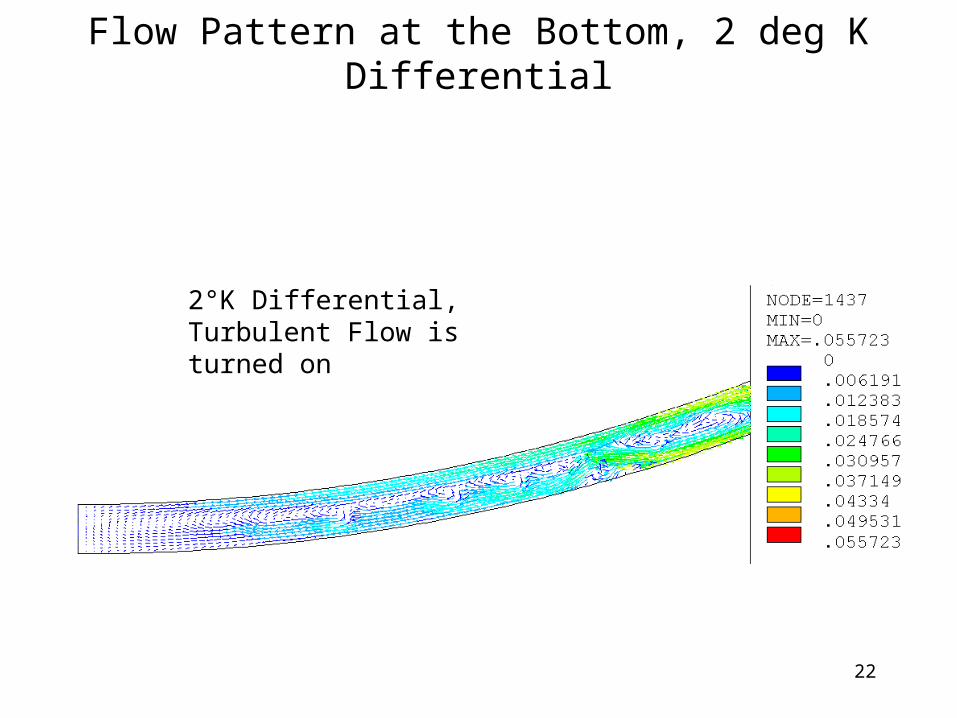
Flow Pattern at the Bottom, 2 deg K Differential
2°K Differential, Turbulent Flow is turned on

23
Reynold’s Number
h = 0.012 m thickness of the argon layermu = 0.00026 kg/(m-sec) viscosity
Delta T Vmax R Rm/sec laminar turbulent
0.5 0.041 2,6681 0.044 2,8632 0.09 5,8574 0.231 15,033 1276
The effective channel depth for flow is half the thickness of the fluid layer (full thickness flows are possible but have not been observed)
R = 2*p*V*h/mu for full thickness flow (the hydraulic diameter is 2*h)
Transitional flow for 2000 < R < 4000
Turbulent flow if V>0.062 m/sec
Note that in the range of interest Reynolds number with turbulence activated will always be lower than required to justify activation.
Laminar values for convection are used. These are expected to be conservative.

24
Three Dimensional Flow Results
• A 3D model was run to see if convective cells consisting of near through thickness flows would develop.
• The 3D results hint at slightly increased heat flow compared to 2D results but these coarser mesh models predict about 40% of the heat flux of the fine mesh 2D model.– The 3D results were compared to comparably meshed 2D
results to estimate the effect of 3D vs 2D flows.
– 3D models (and the comparably meshed 2D models) may not have been run long enough to establish a quasi-steady state heat flow (net heat flow tends to increase slowly with time from the intial conditions of zero velocity and linear thermal gradients).

25
Circulation Pattern, Inside and Outside Views at the Same Time
Inside View
Surface is ¼ thickness
Outside View
Surface is 3/4 thickness
2°K differential, 4 element layers in model, the inner two layers are shown
See the movie files “D3-velocities.avi” and “D3-flux.avi” (use Windows media player)

26
Circulation at an Earlier Time (Eddy’s are not Stable)
Inside View
Surface is ¼ thickness
Outside View
Surface is 3/4 thickness

27
Comparison of 2D and 3D Convection Coefficient Results
Net Conduction Coeficient, W/m^2/deg K
0
10
20
30
40
50
60
70
80
90
0 0.5 1 1.5 2 2.5
Delta Temp
W/m
^2
/K
Lam phase 3
Lam phase 3
Lam 3D
Lam coarse 4
lam coarse 8
turb 3D
turb coarse 4
turb coarse 8
turb phase 3
Fine mesh 2D results
Fine mesh 2D results earlier runs
Coarser mesh 2D and 3D results. Coarse 4 and 8 are 2D results with the coarse 8 mesh being similar to the 3D mesh.
3D results give somewhat higher convection than similarly meshed 2D results. Fine mesh laminar 2D results are used.

28
Outer Annulus, Equation for H
Convection Coefficient Across 12 mm fluid filled gap
y = 7.5091Ln(x) + 47.613
R2 = 0.9874
0
20
40
60
80
100
120
0 2 4 6 8 10
Delta T
H, W
/m^
2/K
0
2000
4000
6000
8000
10000
12000
Re,
dim
ensi
on
less
H, Laminar
H, turbulent
Re, Laminar
Re, turbulent
Log. (H, Laminar)
The equation fits the laminar results and was used in the runs reported on subsequent slides.

29
Interaction Between Conduction and Convection Solutions
• Convection Calculations (CFD)– Most convection models were run with uniform temperatures on the inner
and outer walls enclosing the 12 mm argon layer.– One convection case used a representative circumferential temperature
distribution on the ID and gave 90% of the uniform temperature heat transport.
• Thermal solutions use an OD convection coefficient that increases with increasing temperature. This is derived from uniform wall temperature results.– The following slides show that, for uniform temperature walls, heat is
removed faster from the bottom of the OD of the calorimeter and deposited further up on the heat sink’s ID (for ΔT < 2°K).
– The use of the temperature dependent convection coefficient has the effect of increasing heat flow from the bottom of the OD of the calorimeter because that region is warmer.
I reduced convection coefficients to 90% of the value obtained for uniform wall temperatures to account for the reduction in film coefficient obtained from the realistic temperature distribution. I think this ensures that the thermal results are conservative.
The temperature dependent convection coefficient is needed to accommodate the axial temperature variation seen on the OD of the calorimeter. It also gives a bit more heat removal at the bottom compared to the top but doesn’t bias heat flux as heavily to the lower, warmer, areas at nominal heat loads as the CFD solution.

30
Heat Flux at 0.5°K Differential (Turbulent Option Off)
Heat Flux, W/m^2, vs Angle (+90 at top)
0
10
20
30
40
50
60
-90.00 -70.00 -50.00 -30.00 -10.00 10.00 30.00 50.00 70.00 90.00
Angle, deg
He
at
Flu
x,
W/m
^2
Inner Cylinder
Outer Cylinder
Inner Averaged
Inner Averaged
With inner and outer cylinders held at constant temperatures, heat tends to be removed from the lower regions of the ID and deposited at the higher regions of the OD.
The variation in heat removal on the inner cylinder is more pronounced for low temperature differences.

31
Heat Flux at 2°K Differential
Heat Flux, W/m^2, vs Angle (+90 at top)
0
50
100
150
200
250
-90.00 -70.00 -50.00 -30.00 -10.00 10.00 30.00 50.00 70.00 90.00
Angle, deg
He
at
Flu
x,
W/m
^2
Inner Cylinder
Outer Cylinder
Inner Averaged
Inner Averaged
At a 2°K differential the heat flow is more uniformly distributed making the use of a convection coefficient dependent on the local inner wall temperature justifiable.

32
Inner Annulus
• At Fcal 3 ID and OD are 0.072 and 0.086 m
• Heat leak is ~ 10 W/m2
– Mesh used is shown at right
– ΔT used was 0.15°K*
– Transient analysis is required• Flow is laminar and unstable over time
– V = 0.0065 m/sec
– R = 846 this is < 2000 so flow is laminar
* Based on outer annulus thermal analysis
Guess net heat transfer is ~77 W/m2-°K ΔT ~ 10/77 = 0.13°K (used 0.15°K in run)
End result indicates ΔT ~0.25°K so the heat transfer coefficient is underestimated by this analysis.

33
Inner Annulus Results for 0.15 °K Delta
Estimate time for net flux to decay to zero
Volume of fluid = 8.69E-04 m^3 (Half of an 0.086x0.72 m cylinder 1 m long) 0.000869Mass of fluid = 1.21 kg (density is 1393 kg/m^3)Specific heat = 1078 J/kg-deg-KHeat capacity = 1305 J/deg-K
Net Flux = -0.21 W FEM resultdT/dt fluid = -0.00016 deg K/secChange in 100 sec = -0.016
The run time has not been sufficient to cool the fluid to the equilibrium temperature.
Transmitted flux stabilizes at ~1.61 W (average from 400 to 500 sec). This is 5% higher than the average from 225 to 275 sec.
Heat transfer is 39.8 W/m2-°K
Net flux is slowly decaying with some fluctuations. The net flux of 0.21 W at 178 sec can be expected to persist for a long time if the fluid temperature is above the steady state by 10% or more of the net gradient (i.e. 0.015°K)
ID Solution Results Over Time
1.52
1.54
1.56
1.58
1.6
1.62
1.64
200 250 300 350 400 450 500
time, seconds
Tra
ns
mit
ted
Flu
x, W
-0.2
-0.15
-0.1
-0.05
0
0.05
Ne
t F
lux
, W
Transmitted Flux
Net Flux

34
Use of Inner Annulus Results
• ID temperatures range from about 90.4 to 90.51°K
• The heat flux (heat leak) at the ID is 10 W/m2
• The film coefficient is 39.8 W/m2-°K
• The surface inside the surface shown must be 0.25°K warmer to drive the heat leak (10 W/m2/39.8 W/m2-°K)
Temperatures at the model ID
Convection applies between the ID surface shown and another surface inside this surface (not shown or modeled).

35
Solid Copper Zones
Solid copper zones jacket the ID and OD of each module as shown

36
Increased Heat Loads
• The following models all have:
– 10 W/m2 heat leak at the ID (unless otherwise noted)
– Ohmic heating of 4.95 W/m3, scaled with heat load
– Temperature dependent Convection at the OD• Laminar flow results used
• Convection coefficient reduced 10% based on evaluating convection with a representative temperature profile on the id.
• The convection coefficient at each location was assigned based on the temperature at that location.
– Several iterations were required to converge on stable temperatures.

37
Summary of Results
Ohmic ID MaxHeat Load heating heat load Temp min max
20% W/m^2 deg K deg K deg K
Nominal yes 10 0.52 0.22 0.436xNominal yes 10 2.11 0.66 1.6610xNominal yes 10 3.31 0.97 2.5820xNominal yes 10 6.22 1.69 4.7710xNominal yes 20 3.43 1.03 2.66
OD Annulus Inner T
See above for more information about run parameters
The maximum temperature listed is the increase over the outer wall in contact with the 12 mm thick argon layer. This surface was fixed at 90°K.
The “OD Annulus Inner T” gives the minimum and maximum temperatures on the aluminum tube that forms the inner wall of the 12 mm outer argon jacket.

38
Nominal Heat Load + Ohmic Heating and 10 W/m2 ID Heat Leak

39
6xNominal Heat Load + Ohmic Heating and 10 W/m2 ID Heat Leak

40
10xNominal Heat Load + Ohmic Heating and 10 W/m2 ID Heat Leak

41
20xNominal Heat Load + Ohmic Heating and 10 W/m2 ID Heat Leak

42
10xNominal Heat Load + Ohmic Heating and 20 W/m2 ID Heat Leak