
09/25/2007 - 09/26/2007 Meeting Presentation on Task 2 ...
11
Task 2: Evaluation of the Causes & Mechanisms of IASCC in PWRs - Prior Effort Overview September 25-26, 2007 Nuclear Engineering Division Argonne National Laboratory, Argonne, IL 60439 Work sponsored by the US Nuclear Regulatory Commission Investigators: Yiren Chen, Omesh Chopra, Hee Chung, Gene Gruber, Wes Ruther, and Bill Shack Experimental Effort: Ron Clark, Loren Knoblich, Ed Listwan, and Don Perkins
Transcript of 09/25/2007 - 09/26/2007 Meeting Presentation on Task 2 ...

Task 2: Evaluation of the Causes &Mechanisms of IASCC in PWRs -Prior Effort Overview
September 25-26, 2007
Nuclear Engineering Division
Argonne National Laboratory, Argonne, IL 60439
Work sponsored by the US Nuclear Regulatory Commission
Investigators: Yiren Chen, Omesh Chopra, Hee Chung,Gene Gruber, Wes Ruther, and Bill Shack
Experimental Effort: Ron Clark, Loren Knoblich,Ed Listwan, and Don Perkins

2Work sponsored by theUS Nuclear Regulatory Commission
Task Objective & Approach
! Investigate modes of degradation of austenitic SS core internals in PWRs as
a function of fluence, material chemistry, & cold work
– Effects of high fluence on IASCC susceptibility
– Neutron irradiation embrittlement, i.e., loss of fracture toughness
– Void swelling behavior
– Effect of cold work relative to solution annealed SSs
– Effectiveness of mitigative measures, e.g., GBE treatment, low-S content
! Irradiations in BOR-60 reactor in Dimitrovgrad, Russia
– SA & CW Types 304, 304L, 316, 316LN, & 347 SS
– GBE treated Type 304 & 316 SS, & Alloy 690
– CF-3 & CF-8 cast SSs
– Several commercial & lab heats of SSs with low or high S or O content
! EBR-II Type 304 SS component irradiated in sodium to !50 dpa at 370°C
– Tested in air, and high- & low-DO high-purity water at 289°C
3Work sponsored by theUS Nuclear Regulatory Commission
Task Status
! BOR-60 SSRT specimens irradiated up to !10 dpa and TEM disk specimens
irradiated up to !20 dpa are available for testing;
arrangements are being made to obtain the SSRT & TEM disk specimens
irradiated to !40 dpa
! Completed SSRT tests on BOR-60 specimens irradiated to 10 dpa to
– obtain baseline data in air
– compare results for common materials irradiated to comparable dose
level in the Halden reactor
! Examined void swelling behavior & characterized microstructure of BOR-60
TEM disk specimens from several heats of austenitic SSs and Alloy 690
irradiated to !25 dpa.
4Work sponsored by theUS Nuclear Regulatory Commission
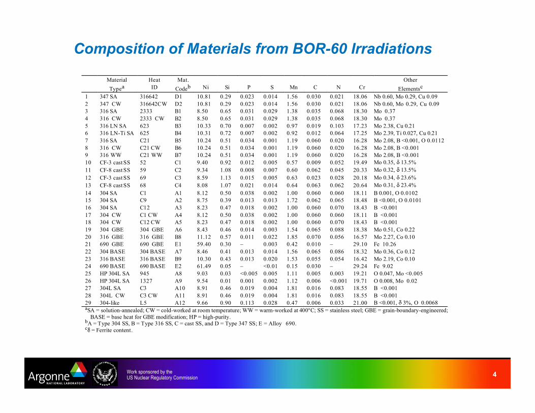
Composition of Materials from BOR-60 Irradiations
Material
Typea
Heat
ID
Mat.
Codeb
Ni
Si
P
S
Mn
C
N
Cr
Other
Elementsc
1 347 SA 316642 D1 10.81 0.29 0.023 0.014 1.56 0.030 0.021 18.06 Nb 0.60, Mo 0.29, Cu 0.09
2 347 CW 316642CW D2 10.81 0.29 0.023 0.014 1.56 0.030 0.021 18.06 Nb 0.60, Mo 0.29, Cu 0.09
3 316 SA 2333 B1 8.50 0.65 0.031 0.029 1.38 0.035 0.068 18.30 Mo 0.37
4 316 CW 2333 CW B2 8.50 0.65 0.031 0.029 1.38 0.035 0.068 18.30 Mo 0.37
5 316 LN SA 623 B3 10.33 0.70 0.007 0.002 0.97 0.019 0.103 17.23 Mo 2.38, Cu 0.21
6 316 LN-Ti SA 625 B4 10.31 0.72 0.007 0.002 0.92 0.012 0.064 17.25 Mo 2.39, Ti 0.027, Cu 0.21
7 316 SA C21 B5 10.24 0.51 0.034 0.001 1.19 0.060 0.020 16.28 Mo 2.08, B <0.001, O 0.0112
8 316 CW C21 CW B6 10.24 0.51 0.034 0.001 1.19 0.060 0.020 16.28 Mo 2.08, B <0.001
9 316 WW C21 WW B7 10.24 0.51 0.034 0.001 1.19 0.060 0.020 16.28 Mo 2.08, B <0.001
10 CF-3 cast SS 52 C1 9.40 0.92 0.012 0.005 0.57 0.009 0.052 19.49 Mo 0.35, 13.5%
11 CF-8 cast SS 59 C2 9.34 1.08 0.008 0.007 0.60 0.062 0.045 20.33 Mo 0.32, 13.5%
12 CF-3 cast SS 69 C3 8.59 1.13 0.015 0.005 0.63 0.023 0.028 20.18 Mo 0.34, 23.6%
13 CF-8 cast SS 68 C4 8.08 1.07 0.021 0.014 0.64 0.063 0.062 20.64 Mo 0.31, 23.4%
14 304 SA C1 A1 8.12 0.50 0.038 0.002 1.00 0.060 0.060 18.11 B 0.001, O 0.0102
15 304 SA C9 A2 8.75 0.39 0.013 0.013 1.72 0.062 0.065 18.48 B <0.001, O 0.0101
16 304 SA C12 A3 8.23 0.47 0.018 0.002 1.00 0.060 0.070 18.43 B <0.001
17 304 CW C1 CW A4 8.12 0.50 0.038 0.002 1.00 0.060 0.060 18.11 B <0.001
18 304 CW C12 CW A5 8.23 0.47 0.018 0.002 1.00 0.060 0.070 18.43 B <0.001
19 304 GBE 304 GBE A6 8.43 0.46 0.014 0.003 1.54 0.065 0.088 18.38 Mo 0.51, Co 0.22
20 316 GBE 316 GBE B8 11.12 0.57 0.011 0.022 1.85 0.070 0.056 16.57 Mo 2.27, Co 0.10
21 690 GBE 690 GBE E1 59.40 0.30 – 0.003 0.42 0.010 – 29.10 Fe 10.26
22 304 BASE 304 BASE A7 8.46 0.41 0.013 0.014 1.56 0.065 0.086 18.32 Mo 0.36, Co 0.12
23 316 BASE 316 BASE B9 10.30 0.43 0.013 0.020 1.53 0.055 0.054 16.42 Mo 2.19, Co 0.10
24 690 BASE 690 BASE E2 61.49 0.05 – <0.01 0.15 0.030 – 29.24 Fe 9.02
25 HP 304L SA 945 A8 9.03 0.03 <0.005 0.005 1.11 0.005 0.003 19.21 O 0.047, Mo <0.005
26 HP 304L SA 1327 A9 9.54 0.01 0.001 0.002 1.12 0.006 <0.001 19.71 O 0.008, Mo 0.02
27 304L SA C3 A10 8.91 0.46 0.019 0.004 1.81 0.016 0.083 18.55 B <0.001
28 304L CW C3 CW A11 8.91 0.46 0.019 0.004 1.81 0.016 0.083 18.55 B <0.001
29 304-like L5 A12 9.66 0.90 0.113 0.028 0.47 0.006 0.033 21.00 B <0.001, 3%, O 0.0068 aSA = solution-annealed; CW = cold-worked at room temperature; WW = warm-worked at 400°C; SS = stainless steel; GBE = grain-boundary-engineered;
BASE = base heat for GBE modification; HP = high-purity. bA = Type 304 SS, B = Type 316 SS, C = cast SS, and D = Type 347 SS; E = Alloy 690. c = Ferrite content.
5Work sponsored by theUS Nuclear Regulatory Commission
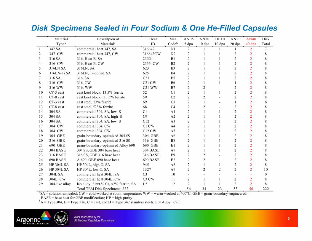
Disk Specimens Sealed in Four Sodium & One He-Filled Capsules
Material
Typea
Descritpion of
Materiala
Heat
ID
Mat.
Codeb
AN05
5 dpa
AN10
10 dpa
HE10
10 dpa
AN20
20 dpa
AN40
40 dpa
Disk
Total
1 347 SA commercial heat 347, SA 316642 D1 2 1 1 1 2 7
2 347 CW commercial heat 347, CW 316642CW D2 2 1 1 2 2 8
3 316 SA 316, Heat B, SA 2333 B1 2 1 1 2 2 8
4 316 CW 316, Heat B, CW 2333 CW B2 2 1 1 2 2 8
5 316LN SA 316LN, SA 623 B3 2 1 1 2 2 8
6 316LN-Ti SA 316LN, Ti-doped, SA 625 B4 2 1 1 2 2 8
7 316 SA 316, SA C21 B5 2 1 1 2 2 8
8 316 CW 316, CW C21 CW B6 2 1 1 1 2 8
9 316 WW 316, WW C21 WW B7 2 2 - 2 2 8
10 CF-3 cast cast keel block, 13.5% ferrite 52 C1 2 1 1 2 2 8
11 CF-8 cast cast keel block, f13.5% ferrite 59 C2 2 2 - 2 2 8
12 CF-3 cast cast steel, 23% ferrite 69 C3 2 1 - 1 2 6
13 CF-8 cast cast steel, f23% ferrite 68 C4 2 2 - 2 2 8
14 304 SA commercial 304, SA, low S C1 A1 2 1 1 2 2 8
15 304 SA commercial 304, SA, high S C9 A2 2 1 1 2 2 8
16 304 SA commercial 304, SA, low S C12 A3 2 1 1 2 2 8
17 304 CW commercial 304, CW C1 CW A4 2 1 1 2 2 8
18 304 CW commercial 304, CW C12 CW A5 2 1 1 2 2 8
19 304 GBE grain-boundary-optimized 304 SS 304 GBE A6 2 1 1 2 2 8
20 316 GBE grain-boundary-optimized 316 SS 316 GBE B8 2 1 1 2 2 8
21 690 GBE grain-boundary-optimized Alloy 690 690 GBE E1 2 1 1 2 2 8
22 304 BASE 304 SS, GBE 304 base heat 304 BASE A7 2 1 1 2 2 8
23 316 BASE 316 SS, GBE 316 base heat 316 BASE B9 2 2 - 2 2 8
24 690 BASE A 690, GBE 690 base heat 690 BASE E2 2 2 - 2 2 8
25 HP 304L SA HP 304L, high O, SA 945 A8 2 1 1 2 2 8
26 HP 304L SA HP 304L, low O, SA 1327 A9 2 2 2 2 2 10
27 304L SA commercial heat 304L, SA C3 10 - - - - - 0
28 304L CW commercial heat 304L, CW C3 CW 11 2 1 1 2 2 8
29 304-like alloy lab alloy, 21wt.% Cr, !2% ferrite, SA L5 12 2 1 1 2 2 8
Total TEM Disk Specimens: 222 56 34 23 53 56 222 aSA = solution-annealed; CW = cold-worked at room temperature; WW = warm-worked at 400°C; GBE = grain-boundary-engineered;
BASE = base heat for GBE modification; HP = high-purity. bA = Type 304, B = Type 316, C = cast, and D = Type 347 stainless steels; E = Alloy 690.

6Work sponsored by theUS Nuclear Regulatory Commission
Bundle & Specimen Identification & Target Dose for SSRT Tests
Target/Actual
dpa
Bun dle
Code
Tensil e Specimen
IDs
Target/Actual
dpa
Bun dle
Code
Tensil e Specimen
IDs
5 / 5.5 5-1 D1-1, D2-1, D2-2, B3-1 10 / 10.2 10-1 D1-2, D1-3, D2-3, D2-4
5 / 5.5 5-2 A5-1, A6-1, B8-1, E1-1 10 / 10.2 10-2 B1-1, B1-2, B2-1, B2-2
5 / 5.5 5-3 B4-1, B5-1, B6-1, B6-2 10 / 11.8 10-3 B3-2, B3-3, B4-2, B4-3
5 / 4.8 5-4 A7-1, B9-1, E2-1, A8-1 10 / 11.8 10-4 B5-2, B5-3, B5-4, B6-3
5 / 4.8 5-5 A1-1, A2-1, A3-1, A4-1 10 / 10.4 10-5 B6-4, B6-5, B7-1, B7-2
5 / 4.8 5-6 A9-1, A10-1, A11-1, A12-1 10 / 10.4 10-6 C1-1, C1-2, C2-1, C2-2
10 / 9.1 10-7 A1-2, A1-3, A2-2, A2-3 40 / 47.5 20-1 B4-4, B4-5, C3-2, C4-2
10 / 9.1 10-8 A3-2, A3-3, A4-2, A4-3 40 / 47.5 20-2 A5-4, E 1-4, A9-5, A11-4
10 / 9.1 10-9 A5-2, A5-3, A6-2, A6-3 40 / 47.5 20-3 C3-1, C4-1, A6-4, B8-4
10 / 9.6 10-10 B8-2, B8-3, E1-2, E1-3 40 / 47.5 20-4 A8-4, A9-4, A12-4, A12-5
10 / 9.6 10-11 A7-2, A7-3, B9-2, B9-3 40 / 45.0 40-1 D1-4, D1-5, D2-5, D2-6
10 / 9.6 10-12 E 2-2, E2-3, A8-2, A8-3 40 / 47.2 40-2 B4-6, B5-5, B5-6, B6-6
10 / 9.6 10-13 A9-2, A9-3, A10-2, A10-3 40 / 48.1 40-3 B2-3, B7-3, B7-4, A9-6, A12-6
10 / 9.1 10-14 A11-2, A11-3, A12-2, A12-3
Specimens listed in red are in Russia, these specimens will be available for testing by June 2007.

7Work sponsored by theUS Nuclear Regulatory Commission
Material & Target Dose of SSRT Specimens from BOR-60 Irradiations Material
Typea
Descritpion of
Materiala
Heat
ID
Mat.
Codeb
SSRT
5 dpa
SSRT
10 dpa
SSRT
10 dpa
SSRT
40 dpa
Mat.
Codeb
SSRT
Total
1 347 SA commercial heat 347, SA 316642 D1 1 2 – 2 D1 5
2 347 CW commercial heat 347, CW 316642CW D2 2 2 – 2 D2 6
3 316 SA 316, Heat B, SA 2333 B1 – 2 – – B1 2
4 316 CW 316, Heat B, CW 2333 CW B2 – 2 – 1 B2 3
5 316LN SA 316LN, SA 623 B3 1 2 – – B3 3
6 316LN-Ti SA 316LN, Ti-doped, SA 625 B4 1 2 – 3 B4 6
7 316 SA 316, SA C21 B5 1 3 – 2 B5 6
8 316 CW 316, CW C21 CW B6 2 3 – 1 B6 6
9 316 WW 316, warm-worked C21 WW B7 – 2 – 2 B7 4
10 CF-3 cast cast keel block, 13.5% ferrite 52 C1 – 2 – – C1 2
11 CF-8 cast cast keel block, 13.5% ferrite 59 C2 – 2 – – C2 2
12 CF-3 cast cast steel, 23% ferrite 69 C3 – – – 2 C3 2
13 CF-8 cast cast steel, 23% ferrite 68 C4 – – – 2 C4 2
14 304 SA commercial heat 304, SA, low S C1 A1 1 – 2 – A1 3
15 304 SA commercial heat 304, SA, high S C9 A2 1 – 2 – A2 3
16 304 SA commercial heat 304, SA, low S C12 A3 1 – 2 – A3 3
17 304 CW commercial heat 304, CW C1 CW A4 1 – 2 – A4 3
18 304 CW commercial heat 304, CW C12 CW A5 1 – 2 1 A5 4
19 304 GBE grain-boundary-optimized 304 SS 304 GBE A6 1 – 2 1 A6 4
20 316 GBE grain-boundary-optimized 316 SS 316 GBE B8 1 – 2 1 B8 4
21 690 GBE grain-boundary-optimized Alloy 690 690 GBE E1 1 – 2 1 E1 4
22 304 BASE 304 SS, base heat of 304 GBE 304 BASE A7 1 – 2 – A7 3
23 316 BASE 316 SS, base heat of 316 GBE 316 BASE B9 1 – 2 – B9 3
24 690 BASE Alloy 690, base heat of 690 GBE 690 BASE E2 1 – 2 – E2 3
25 HP 304L SA HP 304L, high O, SA 945 A8 1 – 2 1 A8 4
26 HP 304L SA HP 304L, low O, SA 1327 A9 1 – 2 3 A9 6
27 304L SA commercial heat 304L, SA C3 A10 1 – 2 – A10 3
28 304L CW commercial heat 304L, CW C3 CW A11 1 – 2 1 A11 4
29 304-like alloy lab alloy, 21wt.% Cr, !2% ferrite, SA L5 A12 1 – 2 3 A12 6
Total SSRT Specimens 109 24 24 32 29 109 aSA = solution-annealed; CW = cold-worked at room temperature; WW = warm-worked at 400°C;
GBE = grain-boundary-engineered; BASE = base heat for GBE modification; HP = high-purity. bA = Type 304 SS; B = Type 316 SS; C = cast austenitic SS; D = Type 347 SS; E = Alloy 690.
8Work sponsored by theUS Nuclear Regulatory Commission
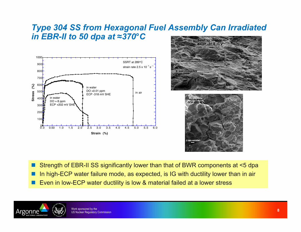
Type 304 SS from Hexagonal Fuel Assembly Can Irradiatedin EBR-II to 50 dpa at !370°C
! Strength of EBR-II SS significantly lower than that of BWR components at <5 dpa
! In high-ECP water failure mode, as expected, is IG with ductility lower than in air
! Even in low-ECP water ductility is low & material failed at a lower stress
0
100
200
300
400
500
600
700
800
900
1000
0.0 0.50 1.0 1.5 2.0 2.5 3.0 3.5 4.0 4.5 5.0 5.5 6.0
Str
es
s
(%)
Strain (%)
SSRT at 289°C
strain rate 2.5 x 10- 7
s- 1
in air
in water
DO !0.01 ppm
ECP -318 mV SHE
in water
DO ! 8 ppm
ECP +202 mV SHE
9Work sponsored by theUS Nuclear Regulatory Commission
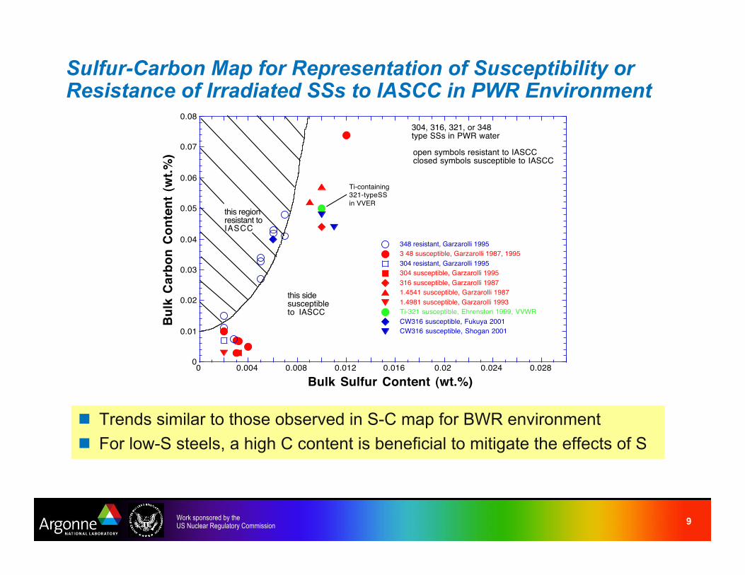
Sulfur-Carbon Map for Representation of Susceptibility orResistance of Irradiated SSs to IASCC in PWR Environment
! Trends similar to those observed in S-C map for BWR environment
! For low-S steels, a high C content is beneficial to mitigate the effects of S
0
0.01
0.02
0.03
0.04
0.05
0.06
0.07
0.08
0 0.004 0.008 0.012 0.016 0.02 0.024 0.028
348 resistant, Garzarolli 1995
3 48 susceptible, Garzarolli 1987, 1995
304 resistant, Garzarolli 1995
304 susceptible, Garzarolli 1995
316 susceptible, Garzarolli 1987
1.4541 susceptible, Garzarolli 1987
1.4981 susceptible, Garzarolli 1993
Ti-321 susceptible, Ehrensten 1999, VVWR
CW316 susceptible, Fukuya 2001
CW316 susceptible, Shogan 2001
Bu
lk C
arb
on
Co
nte
nt
(wt.
%)
Bulk Sulfur Content (wt.%)
this regionresistant toIASCC
this sidesusceptibleto IASCC
304, 316, 321, or 348type SSs in PWR water
Ti-containing321-typeSS
in VVER
open symbols resistant to IASCCclosed symbols susceptible to IASCC

10Work sponsored by theUS Nuclear Regulatory Commission
Assessment of Void Swelling in Austenitic SS Core Internals
! Based on limited data, swelling in thin-walled tubes & baffle bolts not a concern.
Validity of this conclusion should be scrutinized as additional data become available
! PWR baffle reentrant corners most likely to experience high swelling rates.
– Preliminary estimates indicate that void swelling is unlikely to exceed threshold of
!4% for swelling rates to reach the steady state of 1%/dpa.
– However, more accurate quantification of max temp of reentrant corners at EOL &
life extension situations would be useful
0
0.05
0.1
0.15
0.2
0.25
0.3
0.35
0.4
0 10 20 30 40 50 60 70 80
Ringhals Thimble, CW316
Lock Bar, SA304
Tihange Baffle Bolt, CW316
Baffle Bolt, SA347
JPWR thimble, CW316
WPWR thimble, CW316
Vo
id S
we
llin
g (
%)
Neutron Damage (dpa)
PWR Internals
SA304, CW316,
SA347 SSs

11Work sponsored by theUS Nuclear Regulatory Commission
Ball Punch Tests on TEM Disks
! Completed tests on several nonirradiated materials;
tests on irradiated materials will be initiated in Oct. 2007
! Typical load-deflection curve shows: I - elastic bending,
II - plastic bending, III - plastic membrane stretching, &
VI - max. load & plastic instability with load drop due to crack
propagation or through thickness thinning
! Use materials with known fracture toughness to develop correlation
between ball punch fracture energy data with fracture toughness
0
100
200
300
400
500
0 0.2 0.4 0.6 0.8 1
Load (
N)
Displacement (mm)
0
100
200
300
400
500
600
700
0
100
200
300
400
500
600
700
0 50 100 150 200 250 300
Load (
N)
No
rma
lize
d D
efo
rma
tion
En
erg
y (J
/mm
3 )
Normalized Deflection (%)
Region II Region III Region IV
Region I
Fracture
Heat 18474
Energy
Load


