
07 48 00 MFITM S SERIES GUIDE SPECIFICATION constructed exterior assembly must have a minimum 90%...
12
07 48 00 MFI TM S SERIES GUIDE SPECIFICATION KNIGHT WALL SYSTEMS – 1.855.KWS.WALL Edit Date: 2/25/2016 MFI, ThermaStop, ThermaBracket, PanelRail and RevealRail are Trademarks of Knight Wall Systems, Inc. SPEC NOTE: THESE DRAWINGS ARE TO BE TREATED AS A SPEC NOTE AND ONLY INTENDED TO ASSIST WITH IDENTIFICATION OF COMPONENTS. THEY ARE NOT INTENDED FOR INCORPORATION INTO THE FINAL SPECIFICATION. HORIZONTAL S-RAIL (+ VERTICAL PanelRail) VERTICAL S-RAIL (+ HORIZONTAL PanelRail) SECTION VIEW PLAN VIEW SECTION VIEW PLAN VIEW
Transcript of 07 48 00 MFITM S SERIES GUIDE SPECIFICATION constructed exterior assembly must have a minimum 90%...

07 48 00
MFITM S SERIES GUIDE SPECIFICATION
KNIGHT WALL SYSTEMS – 1.855.KWS.WALL Edit Date: 2/25/2016 MFI, ThermaStop, ThermaBracket, PanelRail and RevealRail are Trademarks of Knight Wall Systems, Inc.
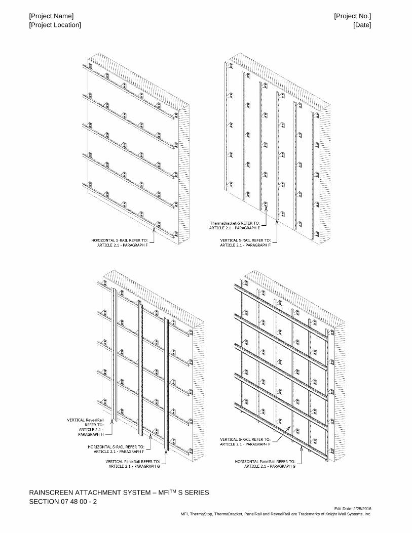
SPEC NOTE: THESE DRAWINGS ARE TO BE TREATED AS A SPEC NOTE AND ONLY INTENDED TO ASSIST WITH IDENTIFICATION OF COMPONENTS. THEY ARE NOT INTENDED FOR INCORPORATION INTO THE FINAL SPECIFICATION.
HORIZONTAL S-RAIL (+ VERTICAL PanelRail)
VERTICAL S-RAIL (+ HORIZONTAL PanelRail)
SECTION VIEW PLAN VIEW
SECTION VIEW PLAN VIEW
[Project Name] [Project No.]
[Project Location] [Date]
RAINSCREEN ATTACHMENT SYSTEM – MFITM S SERIES
SECTION 07 48 00 - 2 Edit Date: 2/25/2016
MFI, ThermaStop, ThermaBracket, PanelRail and RevealRail are Trademarks of Knight Wall Systems, Inc.
[Project No.] [Project Name]
[Date] [Project Location]
[Design Firm] RAINSCREEN ATTACHMENT SYSTEM – MFITM S SERIES
07 48 00 - 3 Edit Date: 2/25/2016 MFI, ThermaStop, ThermaBracket, PanelRail and RevealRail are Trademarks of Knight Wall Systems, Inc.
SPEC NOTE: THERMABRACKET AND RAIL ATTACHMENT SYSTEM FOR MINERAL FIBER INSULATION:
This guide specification is intended for use when specifying an exterior wall assembly consisting of a fully engineered thermally broken highly corrosion resistant rainscreen attachment system fastened directly to the substrate for placement of up to 6-inches of exterior mineral fiber insulation between brackets.
This rainscreen attachment system is versatile and suitable for common face fastened rainscreen panel assemblies and concealed fastener panels such as (but not limited to) metal panels, fiber cement, phenolic panels, Aluminum Composite Material (ACM), stone cladding, and Portland cement plastering.
Thermally isolated brackets (ThermaBracketTM) are attached to the substrate then the primary rail (S-Rail) is
attached to the brackets horizontally or vertically.
Additional secondary rail components (PanelrailTM and/or RevealRailTM) are available to meet additional requirements for cladding attachment, panel layout or to increase the air cavity/system depth. Both secondary rails are compatible with the S-Rail and are 0.75 inches in depth.
The most common configuration is the ThermaBracket-S plus S-Rail. The S-series (Static) rail is fixed
dimensionally to the bracket with only slight adjustability of 1/8-inch and has the ability of adding specially designed shims between the thermal isolator and sheathing at 1/8-inch increments to account for substrate irregularities. These do not increase the thermal transmittance and fits square, straight and bears evenly for a structurally secure and sound connection. This keeps the exterior cladding as shallow as possible. The S-Rail creates an air cavity of 0.75 inches from behind the cladding to face of insulation. When a secondary rail is added to the assembly, the air cavity depth is increased to 1.5 inches.
Please contact manufacture for further information or questions.
KNIGHT WALL SYSTEMS, inc
28308 N. Cedar Road - Deer Park, WA 99006
Toll Free: 1.855.KWS.WALL (597.9255)
Telephone: 509.262.0104
Fax: 509.262.0106
Web: www.knightwallsystems.com
E-mail: [email protected]
General sales: [email protected]
DISCLAIMER: The manufacturer has reviewed the product information contained in this guide specification. The information
is organized and presented to assist the specification writer working on a construction project to select the appropriate products and to save time in writing the project specification Section. The specification writer is responsible for product selection as well as the use and application of this information, and should contact the manufacturer to ensure that all options are available and that the associated specification information is valid and correct.

[Project Name] [Project No.]
[Project Location] [Date]
RAINSCREEN ATTACHMENT SYSTEM – MFITM S SERIES
SECTION 07 48 00 - 4 Edit Date: 2/25/2016
MFI, ThermaStop, ThermaBracket, PanelRail and RevealRail are Trademarks of Knight Wall Systems, Inc.
SECTION 07 48 00
RAINSCREEN ATTACHMENT SYSTEM (MFI)
PART 1 - GENERAL
1.1 SUMMARY
A. Provide a thermally broken, rainscreen attachment system for attachment of exterior cladding [INSERT TYPE OF CLADDING] installed over exterior mineral fiber insulation.
B. Related Sections:
1. Refer to Division 05 Section “Steel Stud Framing”.
2. [Refer to Division 06 Section “Rough Carpentry” for wood framing.]
3. Refer to Division 06 Section “Sheathing”.
4. Refer to Division 07 Section “Air Barrier”
5. Refer to Division 07 Section “[INSERT TYPE Siding/Cladding Panel]”.
6. Refer to Division 07 Section “Thermal Insulation” for exterior mineral fiber insulation.
1.2 SYSTEM DESCRIPTION
A. System assembly shall include the following components from the substrate out:
1. Substrate: Wall framing assembly and sheathing [Concrete masonry unit wall] [Concrete wall]
2. Weather Resistant/Air Barrier over substrate.
3. Mineral fiber insulation.
4. Thermally broken rainscreen attachment system.
5. Exterior cladding.
B. Design Requirements:
1. Manufacturer is responsible for designing system, including anchorage to structural system and necessary modifications to meet specified requirements and maintain visual design concepts.
2. Employ registered professional engineer, licensed to practice engineering in jurisdiction where Project is located, to engineer each component of rainscreen attachment system.
3. Structural Design: Exterior-insulated rainscreen wall assembly capable of withstanding effects of load and stresses from dead loads, wind loads, ice loads (if applicable) as indicated on Structural General Notes on Structural Drawings, and normal thermal movement without evidence of permanent defects of assemblies or components.
a. Thermal Movements: Provide assemblies that allow for thermal movements resulting from the following maximum ambient temperatures by preventing overstressing of components and other detrimental effects:
1) Temperature Change (range): 120 degrees Fahrenheit (67 degrees C), ambient:
4. Support Framing/Attachment System:
a. Frequency and spacing of brackets as indicated by manufacture in project specific engineering package.
C. Performance Requirements:

[Project No.] [Project Name]
[Date] [Project Location]
[Design Firm] RAINSCREEN ATTACHMENT SYSTEM – MFITM S SERIES
07 48 00 - 5 Edit Date: 2/25/2016 MFI, ThermaStop, ThermaBracket, PanelRail and RevealRail are Trademarks of Knight Wall Systems, Inc.
SPEC NOTE: COORDINATE WITH COMPLETE WALL ASSEMBLY TO DETERMINE APPLICABLE THERMAL PERFORMANCE CRITERIA TO SUIT PROJECT REQUIREMENTS, INCLUDING TOTAL WALL EFFECTIVE R-VALUE (U-FACTOR) REQUIRED.
1. Rainscreen Attachment System Performance: Comply with ANSI/ASHRAE 90.1-2010 maximum U-Value for walls.
2. Thermal Performance:
SPEC NOTE: WALL ASSEMBLY EFFECTIVE R-VALUE SHOULD BE IN ACCORDANCE WITH ASHRAE 90.1-2010 REQUIREMENTS OR LOCALLY ADOPTED VERSION. FOR EXAMPLE IN CLIMATE ZONES 4-8 FOR STEEL FRAMED BUILDINGS THE EFFECTIVE R-VALUE IS 15.63 (U-0.064) PER ASHRAE 90.1-2010.
a. Wall Assembly effective R-Value (U-Factor): [INSERT R-VALUE (U-0.XXX)]
b. Full constructed exterior assembly must have a minimum 90% EFFECTIVE R-value when compared to the exterior insulation’s rated R-Value.
c. Continuous framing profiles (including C- or Z-shaped sections or furring) penetrating insulation not allowed.
d. Perform effective R-Value calculation or modeling in accordance with ASHRAE guidelines.
3. Structural Performance:
a. Framing Members:
1) Test framing components to AAMA TIR- A8-[04] – Section 7.2 to determine structural performance and effective moment of inertia for each perforated component. Minimum Effective Moment of Inertia for Primary Rail: 0.0134 in4.
2) Localized bending stress for eccentrically loaded framing members must be evaluated with the maximum effective length of resisting element not more than 12 inches.
b. Fasteners:
1) Tension shall be taken as sum of direct tension plus tension due to prying for eccentrically loaded connections. Prying may be reduced or eliminated if proven via engineering analysis or testing.
2) Minimum Safety Factor of 3 for both tension and shear values.
3) Combined tension and shear shall be evaluated according to an interaction formula. Sum of terms shall not exceed 1.0.
1.3 SUBMITTALS
A. Product Data: Submit manufacturer’s product literature and descriptions of testing performed on system components to indicate meeting or exceeding specified performance.
B. Shop Drawings:
1. Submit connection details to the cladding manufacturer, showing interface of rainscreen attachment system to substrate and panels with adjacent construction, signed and sealed by Professional Engineer.
2. Show system installation and attachment, including fastener size and spacing.
C. Structural Calculations:
1. Submit rainscreen attachment manufacturer’s comprehensive Structural Design analysis signed and sealed by a Professional Engineer.

[Project Name] [Project No.]
[Project Location] [Date]
RAINSCREEN ATTACHMENT SYSTEM – MFITM S SERIES
SECTION 07 48 00 - 6 Edit Date: 2/25/2016
MFI, ThermaStop, ThermaBracket, PanelRail and RevealRail are Trademarks of Knight Wall Systems, Inc.
D. Samples: Submit following material samples for verification:
1. Wall Brackets: Two (2) samples.
2. Horizontal Rails: Two (2) 12-inch long samples.
E. Test Reports:
1. Test to the following standards and provide written test reports by a third party:
a. AAMA TIR-A8-[04]: Structural Performance of Composite Thermal Barrier Framing Systems – Section 7.2.
2. Comprehensive three-dimensional thermal modeling report indicating framing systems impact on exterior insulation rated R-value.
1.4 QUALITY ASSURANCE
A. Manufacturer Qualifications:
1. Minimum 5 years’ experience specializing in the manufacturing of façade attachment/support framing similar to those specified.
2. Ability to demonstrate conformance to testing requirements.
B. Installer Qualifications:
1. Minimum of 3 years’ documented experience or minimum of 5 completed projects of equivalent scope and quality and recommended by manufacturer to perform work of this Section.
2. Onsite superintendent or foreman overseeing installation on site during entire work of this Section with experience equivalent to installer and in good standing with the manufacturer.
C. Engineer Qualifications: Registered professional engineer experienced in the design of curtain wall systems, anchors, fasteners and licensed to practice engineering in the jurisdiction where Project is located.
D. Pre-Installation Meeting:
1. Discuss sequence and scheduling of work and interface with other trades.
2. Review metal wall framing assemblies for potential interference and conflicts and coordinate layout and support provisions for interfacing work.
3. Review and document methods, procedures and manufacturer’s installation guidelines and safety procedures for exterior wall assembly.
E. Mock-Ups: Coordinate mock-up materials and requirements with mock-up specified in Division 01 [and exterior cladding specification].
1.5 QUALITY CONTROL
A. Single source responsibility:
1. Furnish engineered rainscreen attachment system components under direct responsibility of single manufacturer.
B. Field Measurements: Verify actual supporting and adjoining construction before fabrication.
C. Record field measurements on project record shop drawings.
D. Established Dimensions: Where field measurements cannot be made without delaying work, guarantee dimensions and proceed with fabrication of rainscreen attachment system corresponding to established dimensions.

[Project No.] [Project Name]
[Date] [Project Location]
[Design Firm] RAINSCREEN ATTACHMENT SYSTEM – MFITM S SERIES
07 48 00 - 7 Edit Date: 2/25/2016 MFI, ThermaStop, ThermaBracket, PanelRail and RevealRail are Trademarks of Knight Wall Systems, Inc.
1.6 DELIVERY, STORAGE AND HANDLING
A. Delivery: Deliver materials and components in manufacturers’ original, unopened and undamaged containers or bundles, fully identified. Exercise care to avoid damage during unloading, storing and installation.
B. Store, protect and handle materials and components in accordance with manufacturer recommendations to prevent damage, contamination and deterioration. Keep materials clean, dry, and free of dirt and other foreign matter, and protect from damage due to weather or construction activities.
1.7 SEQUENCING
A. Ordering: Comply with manufacturers’ ordering instructions and lead time requirements to avoid construction delays.
B. Coordinate construction to ensure that assemblies fit properly to supporting and adjoining construction; coordinate schedule with construction in progress to avoid delaying work.
1.8 WARRANTY
A. Manufacturer Warranties:
1. Attachment System: Ten (10) year Limited Warranty.
a. Covers components of the attachment system, including structural failure of components when all the materials and components are supplied and installed per manufacturer’s requirements.
b. Includes labor and material for removal and replacement of defective material.
c. Includes labor to remove and reinstall façade finish panels, finish closures and façade finish accessories necessary to access defective material.
B. Contractor’s Warranties: 2-year labor warranty, starting from [date of Owner acceptance of completed work] [Substantial Completion], to cover repair of materials found to be defective as a result of installation errors.
C. Limitation of Warranties: Exclude repairs, replacement, and corrective work to the substrate, primary structure, finish panels, and/or property – unless otherwise noted above. Warranties exclude mechanical damage due to abuse, neglect, primary structure failure, or forces of nature greater than normal weather conditions.
1.9 MAINTENANCE
A. Extra Materials: For use by Owner in building maintenance and repair, provide [a recommended percentage of] [3 percent] additional rainscreen attachment components in new, unopened cartons, packaged with protective covering for storage and identified with appropriate labels.
PART 2 - PRODUCTS
2.1 RAINSCREEN ATTACHMENT/SUPPORT FRAMING SYSTEM
A. Comply with ANSI/ASHRAE 90.1-2010.
B. Coating Material: ASTM A1046, Zinc-Aluminum-Magnesium, minimum thickness ZM40.
1. ASTM A653 Galvanized steel is not acceptable.
C. Steel Classification: Structural Steel (SS), Grade 50, 50 ksi Yield.
[Project Name] [Project No.]
[Project Location] [Date]
RAINSCREEN ATTACHMENT SYSTEM – MFITM S SERIES
SECTION 07 48 00 - 8 Edit Date: 2/25/2016
MFI, ThermaStop, ThermaBracket, PanelRail and RevealRail are Trademarks of Knight Wall Systems, Inc.
SPEC NOTE: BRACKETS MAY BE SPACED UP TO 32 INCHES ON CENTER HORIZONTALLY (EVERY OTHER STUD), 36 INCHES VERTICALLY (DEPENDING ON CLADDING WEIGHT,DESIGN WIND PRESSURES, AND TENSION FORCES ON FASTENERS) AND SUPPORT CLADDINGS THAT WEIGH OVER 15 POUNDS PER SQUARE FOOT. THE MAXIMUM ALLOWABLE SPACING AND DEAD LOAD IS DETERMINED PER PROJECT. THIS IS A FUNCTION OF THE LIVE LOAD PLUS THE DEAD LOAD BEING EQUAL TO LESS-THAN THE ALLOWABLE LOAD PER WALL ANCHOR, ACCOUNTING FOR TENSION FORCES, PRY FORCES AND SHEAR FORCES. SPACING AND MAXIMUM LOADS ARE TYPICALLY DETERMINED BY THE MANUFACTURER PER PROJECT.
D. Spacing: Comply with manufacturer’s Professional Engineer’s project specific calculations.
E. Wall Brackets:
1. Minimum 0.074 inch thick (14 gauge) sheet steel.
SPEC NOTE: MINIMUM DIMENSION OF BRACKET WILL BE DETERMINED BY INSULATION THICKNESS. ADDITIONAL DEPTH UP TO 6-INCHES CAN BE ADDED BY THE DESIGNER TO CREATE AESTHETICS DESIRED.
2. Dimensions:
a. Bracket Base: Minimum 3.125 inch high by 2.125 inch wide.
b. Offset Brackets: 2- [3-] [3.5-] [4-] [5-] [6-] inch depth.
1) Align offsets to differing wall planes as shown on Drawings.
3. Pre-Punched Holes: Two wall anchors per bracket.
4. Recommended Product: ThermaBracket-S by Knight Wall Systems or approved equal.
F. Primary Horizontal [Vertical] Rail, Static S-Series.
1. Minimum 0.046-inch thick (18 gauge) [0.054-inch thick (16 gauge)] cold-formed steel.
2. Profile: C channel, two flanges of equal length and one web.
3. Nominal Dimensions: Minimum 1.0 inch flange for attaching to wall bracket and 1.625 inch at web.
4. Pre-Punched Attachment Holes: 1.0 inch on center along length of track and oversized allowing for thermal contraction and expansion of rail without placing stress on brackets.
5. Recommended Product: S-Rail by Knight Wall Systems or approved equivalent.
SPEC NOTE: OPTIONAL SECONDARY RAILS ATTACH TO PRIMARY RAILS TO PROVIDE ADDITIONAL PANEL SUPPORT OR REVEAL CONFIGURATION FOR PANEL DESIGN. USE OF SECONDARY RAILS IS DEPENDENT UPON THE PANEL TYPE, LAYOUT, ITS ORIENTATION AND/OR CONFIGURATION. PLEASE CONTACT KNIGHT WALL SYSTEMS IF THERE IS ANY UNCERTAINTY OR QUESTIONS.
2” PANELRAIL IS TYPICALLY USED. IF PANEL CLADDING HAS LARGE CLIPS THAT REQUIRE ADDITIONAL MATERIAL FOR ATTACHMENT. RAILS ARE ALSO AVAILABLE WITH 3-INCH, 4-INCH, OR 5-INCH FACE FOR FASTENING. SEE GUIDE DETAILS FOR FURTHER INFORMATION AND EXAMPLES OF USE.
G. Secondary Vertical [Horizontal] Rail: Nominal 0.046 inch thick (18 gauge) [0.054-inch thick (16 gauge)] cold-formed steel.
1. Profile: Hat channel with stiffening lips.
2. Profile Depth: 0.75 inches.
3. Girt Fastening Face: 2.0 inches [3.0 inches] [4.0 inches] [5.0 inches] [Manufacturer’s recommendation as Engineered].

[Project No.] [Project Name]
[Date] [Project Location]
[Design Firm] RAINSCREEN ATTACHMENT SYSTEM – MFITM S SERIES
07 48 00 - 9 Edit Date: 2/25/2016 MFI, ThermaStop, ThermaBracket, PanelRail and RevealRail are Trademarks of Knight Wall Systems, Inc.
4. Weep Drains: 0.75 inches diameter at 4 inches on center along flanges to allow for free air flow laterally.
5. Attachment Holes: Locate at 2 inch on center along back to facilitate number 14 self-drilling self-tapping screw attachment to primary rail.
a. Oversize holes to allow for thermal contraction and expansion of rail.
6. Basis of Design: PanelRail™ by Knight Wall Systems.
7. Or approved equal.
SPEC NOTE REVEAL RAIL IS TYPICALLY USED AT VERTICAL JOINTS AT FACE FASTENED PANELS TO CREATE PANEL SEPARATION OR SHADOW EFFECT.
H. Reveal Rail: Nominal 0.046 inch thick (18 gauge) [0.054-inch thick (16 gauge)] cold-formed steel.
1. Profile: Square hat channel with stiffening lips.
2. Depth: 0.75 inches.
3. Dimensions: 2.0 inches at web, 1.625 inches at each flange with 0.25 stiffening lips.
4. Basis of Design: RevealRailTM by Knight Wall Systems or approved equivalent.
I. Thermal Isolation:
1. Material: Injection molded Polyoxymethylene copolymer (POM), non-fiber reinforced.
2. Tensile Yield Strength: 9.57 ksi per ISO 527.
3. Melting Temperature: 329 degrees Fahrenheit per ISO 3146.
4. Components:
a. Wall Anchor Isolation Washer: minimum 0.125 inch thick.
b. Support Wall Substrate Isolation: Minimum 0.375-inch thick at each wall bracket.
c. Rail to Bracket Isolation: Minimum 0.125 inch thick at each connection.
d. Bracket Shim: Match support wall substrate isolator profile; available in 0.125-inch thickness and does not decrease thermal or structural performance of system.
5. Basis of Design: ThermaStop™ Isolators by Knight Wall Systems.
6. Or approved equal.
J. Fasteners:
1. Sufficient length to provide solid attachment to structure as required by manufacturer.
2. Thermally isolated.
SPEC NOTE: SELECT THE FOLLOWING FOR FRAMED SUBSTRATES WITH SHEATHING:
3. Framed substrate with sheathing: Self-drill hex-washer-head stainless steel with 1,000 hour salt-spray rated thermoset polyester coating.
a. Embedment depth: 0.625 inches or three full threads minimum, whichever is greater.
b. Minimum ultimate pull-out capacity from 18 gauge steel: 450 pounds.
SPEC NOTE: SELECT THE FOLLOWING FOR CONCRETE AND CMU SUBSTRATES:
4. Concrete and concrete masonry units substrate:
a. Embedment depth: 1.25 inches minimum.
b. Minimum ultimate pull-out capacity from substrate material: 450 pounds.
c. 1/4 inch Kwik-Con II+ by Hilti

[Project Name] [Project No.]
[Project Location] [Date]
RAINSCREEN ATTACHMENT SYSTEM – MFITM S SERIES
SECTION 07 48 00 - 10 Edit Date: 2/25/2016
MFI, ThermaStop, ThermaBracket, PanelRail and RevealRail are Trademarks of Knight Wall Systems, Inc.
d. 1/4 inch Tapcon by Buildex
e. 1/4 inch UltraCon by Elco Industries
f. Or approved equal.
5. For primary to secondary rail connection: Self-drill hex-washer-head stainless steel with 1,000 hour salt-spray rated thermoset polyester coating.
a. Embedment depth: 0.625 inches or three full threads minimum, whichever is greater.
b. Minimum ultimate pull-out capacity from 18 gauge steel: 450 pounds.
K. Accessories:
1. Bracing, Furring, Bridging, Plates, Gussets, and Clips: Formed sheet steel, thickness as necessary to meet structural requirements for special conditions encountered.
2. Galvanic Protection: Utilize tapes and other methods as necessary to separate and prevent contact between dissimilar metals.
2.2 MINERAL FIBER INSULATION
SPEC NOTE: MINERAL FIBER = MINERAL WOOL = SEMI-RIGID INSULATION.
MINERAL FIBER IS THE PREFERRED INSULATION CHOICE WITH THE MFI-SYSTEM. SPECIFIER MAY INCLUDE BASIS OF DESIGN INSULATION HERE OR IN DIVISION 07 SECTION THERMAL INSULATION. INSULATION BRANDS THAT WORK WITH THE SYSTEM INCLUDE BUT ARE NOT LIMITED TO ROXUL, THERMAFIBER, KNAUF - IF INSULATION IS SPECIFIED HERE, INCLUDE ACCESSORIES SUCH AS FASTENERS, WASHERS, AND TAPES. THICKNESS OF INSULATION IS THE MINIMUM BRACKET DEPTH TO AVOID EXTRA LABOR FOR CUTTING AND FITTING INSULATION.
A. Refer to Section 07 21 00 – Thermal Insulation.
2.3 SIDING/CLADDING PANEL
SPEC NOTE: SPECIFIER OPTION TO INCLUDE SIDING/CLADDING PANEL HERE OR MAKE REFERENCE TO DIVISION 07 SECTION "CLADDING".
A. Refer to Division 07 Section 07 4X XX.
PART 3 - EXECUTION
3.1 EXAMINATION
A. Examine substrates and conditions for compliance with manufacturer requirements for installation conditions affecting performance of the work.
1. Do not proceed with installation until unsatisfactory conditions have been corrected.
2. Ensure weather-resistant barrier (WRB) is installed prior to installing rainscreen attachment system.
3. Ensure fenestration, transitions, discontinuities, sills, and ledgers are flashed and sealed to move moisture to the exterior of the building.
B. Field verify architectural details and mechanical and electrical requirements prior to commencing installation.
C. Commencement of installation constitutes acceptance of existing conditions and acceptance of responsibility for satisfactory performance.
3.2 RAINSCREEN ATTACHMENT SYSTEM INSTALLATION

[Project No.] [Project Name]
[Date] [Project Location]
[Design Firm] RAINSCREEN ATTACHMENT SYSTEM – MFITM S SERIES
07 48 00 - 11 Edit Date: 2/25/2016 MFI, ThermaStop, ThermaBracket, PanelRail and RevealRail are Trademarks of Knight Wall Systems, Inc.
A. Preparation: Review areas of potential interference and conflicts and coordinate layout and support provisions for interfacing work.
B. Installation: Install in strict accordance with manufacturer’s installation instructions.
C. Wall Brackets and Primary Rail:
1. Mount wall brackets at 16 [24] [32] inch on center horizontally [vertically] on support wall (at each stud location).
a. Brackets must be laid out at 0.5 inch increments vertically or horizontally.
b. Tighten screws to substructure to a snug tight condition and not stripped. Do not over-torque beyond manufacturer’s recommendation. If installed using hand tools, verify for each installer at beginning of project using snug-tight criteria. Do not use stripped holes.
2. Thermally isolate wall bracket attachments by sandwiching thermal break material between metal bracket and support wall substrate.
3. Thermally isolate screw fastener washers using material to thermally isolate fastener heads from metal bracket.
4. Mineral Fiber Insulation: Install to expand into and friction fit between wall brackets as specified by Section 072100 prior to installing horizontal rails.
5. Attach horizontal rail to wall bracket stem by use of a self-tapping screw fastener through the pre-punched holes in the rail and into the pre-punched pilot holes on the bracket.
6. Isolate horizontal rail from bracket by sandwiching a thermal break material between rail and bracket stem.
7. Attach horizontal rail at proper pre-punched pilot holes on bracket stem to align plumb and true. Account for irregularities in support wall.
8. Establish and re-establish and restart vertical bracket locations using laser or chalk-line at fenestrations and other obstructions to establish horizontal alignments.
SPEC NOTE: DELETE THE FOLLOWING PARAGRAPH IF SECONDARY RAILS ARE NOT USED.
D. Secondary Rail:
1. Space to make suitable bearing surfaces for each cladding system as instructed by manufacturer and as shown on Architect accepted shop drawings.
2. Begin at bottom and mount to horizontal rails using No. 14 self-drilling self-tapping stainless steel screws.
3. Tighten screws to snug tight. Verify equivalent snug tight condition for installers using hand tools.
4. Install successive vertical rails as required for panel type and engineering.
5. When encountering fenestrations and other openings, mount vertical rails so that fastening points are as close to the lower and upper edges as possible.
E. Touch-up shop-applied protective coatings damaged during handling and installation.
F. Use shearing instruments (i.e. snips, nibbler, etc.) for cutting metal framing components. Saws are not recommended, as the sparks produced during cutting will damage the anti-corrosion coating. If sparks are generated during cutting, be sure the portion of the component to be installed on the building is protected from sparks and that any stockpile near the cutting station is also protected.
G. The systems components should not be cut while installed on the building, unless using a shearing instrument.
H. Replace thermal isolator pieces that break during installation.
I. Provide a 3/8” – 1/2” gap between girts for expansion when multiple lengths of rail are installed.

[Project Name] [Project No.]
[Project Location] [Date]
RAINSCREEN ATTACHMENT SYSTEM – MFITM S SERIES
SECTION 07 48 00 - 12 Edit Date: 2/25/2016
MFI, ThermaStop, ThermaBracket, PanelRail and RevealRail are Trademarks of Knight Wall Systems, Inc.
J. Minimum length of installed cut primary rail is 12” and must be attached to at least two separate wall brackets to prevent rotation of rail. Unsupported cantilever must not exceed 6” unless specified differently by manufacturer’s engineer.
K. Minimum length of installed cut secondary rail is 12” and must be mechanically attached to at least two separate primary rails.
3.3 ERECTION TOLERANCES
A. Maximum Framing Member Variation from True Position: 1/4 inch.
B. Maximum Framing Member Variation from Plane:
1. Individual Framing Members: Do not exceed 1/4 inch in 10 foot.
2. Accumulative Over-all Variation for Wall and Floor System: Do not exceed 1/4 inch.
3.4 FIELD QUALITY CONTROL
A. Manufacturer’s Field Technical Service: Make intermittent and final inspection to verify installation in conformance to manufacturer instructions and suitable as framing assembly for subsequent metal panels, acrylic plastering, and other cladding installations.
1. Confirm snug tight and fastener sizing.
2. Confirm framing members installed in correct orientation.
3.5 ADJUSTING
A. Inspect and adjust after installation. Replace or repair defective work.
B. Adjust, and reconfigure as necessary to accommodate cladding systems for installations over work of this Section. Do not reuse pre-drilled holes unless fastener size is increased.
3.6 SIDING/CLADDING PANEL INSTALLATION – REFER TO SECTION 07 4X XX
A. The cavity must be clear and free from air flow and drainage obstructions.
END OF SECTION 07 48 00
NOTICE: No freedom from any patent owned by Knight Wall Systems or others is to be inferred. Because use conditions and applicable laws may differ from one location to another and may change with time, Customer is responsible for determining whether products and the information in this document are appropriate for
Customer's use and for ensuring that Customer's workplace and disposal practices are in compliance with applicable laws and other government enactments. Knight Wall Systems assumes no obligation or liability for the information in this document. NO EXPRESS WARRANTIES ARE GIVEN EXCEPT FOR ANY APPLICABLE WRITTEN LIMITED WARRANTIES SPECIFICALLY PROVIDED BY KNIGHT WALL SYSTEMS. ALL IMPLIED WARRANTIES INCLUDING THOSE OF
MERCHANTABILITY AND FITNESS FOR A PARTICULAR PURPOSE ARE EXPRESSLY EXCLUDED. Building and/or construction practices unrelated to building materials could greatly affect moisture and the potential for mold formation. No material supplier including Knight Wall Systems can give assurance that
mold will not develop in any specific system.


![ON AN EXTERIOR INITIAL BOUNDARY VALUE …EXTERIOR INITIAL BOUNDARY VALUE PROBLEM FOR NAVIER-STOKES EQUATIONS 119 [36], and Maremonti [34] (cf. further references cited therein). But,](https://static.fdocuments.net/doc/165x107/5f4a98afbce7466bbc329699/on-an-exterior-initial-boundary-value-exterior-initial-boundary-value-problem-for.jpg)


