
04267738
12
1210 IEEE TRANSACTIONS ON POWER ELECTRONICS, VOL. 22, NO. 4, JULY 2007 Nonlinear Modeling of DC/DC Converters Using the Hammerstein’s Approach Francesco Alonge, Member, IEEE, Filippo D’Ippolito, Member, IEEE, Francesco Maria Raimondi, and Salvatore Tumminaro Abstract—This paper deals with the modelling of highly non- linear switching power-electronics converters using black-box identification methods. The duty cycle and the output voltage are chosen, respectively, as the input and the output of the model. A nonlinear Hammerstein-type mathematical model, consisting of a static nonlinearity and a linear time-invariant model, is consid- ered in order to cope with the well-known limitations of the more common small-signal models, (i.e., the entity of the variations of the variables around a well-defined steady-state operating point and the incorrect reproduction of the steady-state behavior corresponding to input step variations from the above steady-state operating point. The static nonlinearity of the Hammerstein model is identified from input–output couples measured at steady state for constant inputs. The linear model is identified from input–output data relative to a transient generated by a suitable pseudorandom binary sequence constructed with two input values used to identify the nonlinearity. The identification procedure is, first, illustrated with reference to a boost dc/dc converter using results of simulations carried out in the PSpice environment as true experimental results. Then, the procedure is experimentally applied on a prototype of the above converter. In order to show the utility of the Hammerstein models, a PI controller is tuned for a nominal model. Simulation and experimental results are displayed with the aim of showing the peculiarities of the approach that is followed. Index Terms—DC/DC converters, Hammerstein model identifi- cation. I. INTRODUCTION M ODELING and simulation are essential tools for both the analysis and design process in power electronics. In particular, with reference to switching converters, it is very difficult to design stable feedback controllers using exact mathe- matical descriptions because of their inherent high nonlinearity. In a switching converter, some conduction configurations exist, depending on the state of conduction of its nonlinear compo- nents (i.e., diodes and transistors and, consequently, as many linear and time-invariant dynamical models can be obtained as Manuscript received July 15, 2006; revised August 7, 2006. A part of this paper was presented at the PESC’04 Conference, Aachen, Germany, June 20–24, 2004. Recommended for publication by Associate Editor B. Fahimi F. Alonge is with the University of Palermo, Viale delle Scienze, Palermo 90128, Italy, and also with the Dipartimento di Ingegneria dell’Automazione e dei Sistemi, University of Palermo (e-mail: [email protected]). F. D’Ippolito and F. M. Raimondi are with the University of Palermo, Viale delle Scienze, Palermo 90128, Italy S. Tumminaro is with STMicroelectronics, Catania I-95121, Italy. Color versions of one or more of the figures in this paper are available online at http://ieeexplore.ieee.org. Digital Object Identifier 10.1109/TPEL.2007.900551 the number of conduction configurations). Then, it is possible to describe the switching converter using a switched model consisting of a set of linear- and time-invariant mathematical models and a logic supervisor which extracts from the above set, the model which corresponds to the actual conduction configuration. Such a switched model gives accurate results when the converter has to be analyzed but, obviously, it is not useful for designing a controller. For control purposes, suitable procedures are brought to ap- proximate models, which describe the essential low-frequency dynamics of the converter, and have to be utilized. Many of these procedures are circuit oriented, implying that circuit idealization and detailed knowledge of the circuit operation are required. As is well known among these procedures, a widely used method for modeling power switching converters controlled by pulse-width modulation (PWM) techniques is the state-space averaging method [1]–[3] which practically links, with certain approximations, all linear models appearing in the switched model. This method enables obtaining a nonlinear mathemat- ical model that is sufficiently accurate when the carrier basic frequency is much higher than the natural frequencies of the power stage. It provides a good tradeoff between accuracy and simplicity of the modeling approach. An advantage of the state-space averaging method is its efficiency compared to that of the switched model because there is not any switching fre- quency ripple and, consequently, the simulation time required by the averaged model is much lower than that required by the switched model [4]. By means of linearization of the nonlinear model around a specific operating point, a small-signal model can be obtained which requires short simulation times and is suitable for designing a controller and describing the converter in presence of small variations of the duty cycle. However, a small-signal model fails in the presence of large signal per- turbations and is not suitable to describe with accuracy the steady-state behavior of the system corresponding to input step variations beginning from the operating point. Instead of using circuit-oriented modeling approaches, the dynamic behavior of power-electronic systems can be modeled using identification techniques. Compared to the circuit-ori- ented modeling approach, the modeling of power-electronics circuits using system identification possesses an effective advantage of simplicity especially for complex converter topologies because detailed knowledge of the circuit operation is not needed. The identification-based approach can be used for identifying whether there are small-signal models or non- linear models. The advantages of this approach are no circuit 0885-8993/$25.00 © 2007 IEEE
-
Upload
dipanjan-das -
Category
Documents
-
view
7 -
download
1
description
paper
Transcript of 04267738

1210 IEEE TRANSACTIONS ON POWER ELECTRONICS, VOL. 22, NO. 4, JULY 2007
Nonlinear Modeling of DC/DC ConvertersUsing the Hammerstein’s Approach
Francesco Alonge, Member, IEEE, Filippo D’Ippolito, Member, IEEE, Francesco Maria Raimondi, andSalvatore Tumminaro
Abstract—This paper deals with the modelling of highly non-linear switching power-electronics converters using black-boxidentification methods. The duty cycle and the output voltage arechosen, respectively, as the input and the output of the model. Anonlinear Hammerstein-type mathematical model, consisting ofa static nonlinearity and a linear time-invariant model, is consid-ered in order to cope with the well-known limitations of the morecommon small-signal models, (i.e., the entity of the variationsof the variables around a well-defined steady-state operatingpoint and the incorrect reproduction of the steady-state behaviorcorresponding to input step variations from the above steady-stateoperating point. The static nonlinearity of the Hammersteinmodel is identified from input–output couples measured at steadystate for constant inputs. The linear model is identified frominput–output data relative to a transient generated by a suitablepseudorandom binary sequence constructed with two input valuesused to identify the nonlinearity. The identification procedure is,first, illustrated with reference to a boost dc/dc converter usingresults of simulations carried out in the PSpice environment astrue experimental results. Then, the procedure is experimentallyapplied on a prototype of the above converter. In order to show theutility of the Hammerstein models, a PI controller is tuned for anominal model. Simulation and experimental results are displayedwith the aim of showing the peculiarities of the approach that isfollowed.
Index Terms—DC/DC converters, Hammerstein model identifi-cation.
I. INTRODUCTION
MODELING and simulation are essential tools for boththe analysis and design process in power electronics.
In particular, with reference to switching converters, it is verydifficult to design stable feedback controllers using exact mathe-matical descriptions because of their inherent high nonlinearity.In a switching converter, some conduction configurations exist,depending on the state of conduction of its nonlinear compo-nents (i.e., diodes and transistors and, consequently, as manylinear and time-invariant dynamical models can be obtained as
Manuscript received July 15, 2006; revised August 7, 2006. A part of thispaper was presented at the PESC’04 Conference, Aachen, Germany, June20–24, 2004. Recommended for publication by Associate Editor B. Fahimi
F. Alonge is with the University of Palermo, Viale delle Scienze, Palermo90128, Italy, and also with the Dipartimento di Ingegneria dell’Automazione edei Sistemi, University of Palermo (e-mail: [email protected]).
F. D’Ippolito and F. M. Raimondi are with the University of Palermo, Vialedelle Scienze, Palermo 90128, Italy
S. Tumminaro is with STMicroelectronics, Catania I-95121, Italy.Color versions of one or more of the figures in this paper are available online
at http://ieeexplore.ieee.org.Digital Object Identifier 10.1109/TPEL.2007.900551
the number of conduction configurations). Then, it is possibleto describe the switching converter using a switched modelconsisting of a set of linear- and time-invariant mathematicalmodels and a logic supervisor which extracts from the aboveset, the model which corresponds to the actual conductionconfiguration. Such a switched model gives accurate resultswhen the converter has to be analyzed but, obviously, it is notuseful for designing a controller.
For control purposes, suitable procedures are brought to ap-proximate models, which describe the essential low-frequencydynamics of the converter, and have to be utilized. Many of theseprocedures are circuit oriented, implying that circuit idealizationand detailed knowledge of the circuit operation are required.
As is well known among these procedures, a widely usedmethod for modeling power switching converters controlled bypulse-width modulation (PWM) techniques is the state-spaceaveraging method [1]–[3] which practically links, with certainapproximations, all linear models appearing in the switchedmodel. This method enables obtaining a nonlinear mathemat-ical model that is sufficiently accurate when the carrier basicfrequency is much higher than the natural frequencies of thepower stage. It provides a good tradeoff between accuracyand simplicity of the modeling approach. An advantage of thestate-space averaging method is its efficiency compared to thatof the switched model because there is not any switching fre-quency ripple and, consequently, the simulation time requiredby the averaged model is much lower than that required by theswitched model [4]. By means of linearization of the nonlinearmodel around a specific operating point, a small-signal modelcan be obtained which requires short simulation times and issuitable for designing a controller and describing the converterin presence of small variations of the duty cycle. However, asmall-signal model fails in the presence of large signal per-turbations and is not suitable to describe with accuracy thesteady-state behavior of the system corresponding to input stepvariations beginning from the operating point.
Instead of using circuit-oriented modeling approaches, thedynamic behavior of power-electronic systems can be modeledusing identification techniques. Compared to the circuit-ori-ented modeling approach, the modeling of power-electronicscircuits using system identification possesses an effectiveadvantage of simplicity especially for complex convertertopologies because detailed knowledge of the circuit operationis not needed. The identification-based approach can be usedfor identifying whether there are small-signal models or non-linear models. The advantages of this approach are no circuit
0885-8993/$25.00 © 2007 IEEE
ALONGE et al.: NONLINEAR MODELING OF DC/DC CONVERTERS USING THE HAMMERSTEIN’S APPROACH 1211
idealization, no detailed knowledge of system operation and thegeneration of an effective reduced-order model, independent ofthe internal structure of the power converter.
In [5] and [6], the identification approach is employed forobtaining small-signal models. NARMAX models valid over awide operating range, obtained by means of either gray-box orblack-box identification techniques, were proposed in [7] and[8].
Another approach for modeling dc–dc converters is that ori-ented to the study of highly nonlinear phenomena, such as chaosand bifurcations, which occur in these converters. A popularapproach is that based on the modeling by means of nonlinearmapping [9]–[15] (i.e., a nonlinear function that relates a sampleof a state vector sequence to the successive sample of sequence);this mapping governs the evolution of the discrete time systemwithout taking into account, explicitly, the time. These nonlinearmaps, however, have not been used for designing a controller fordc/dc converters.
Obviously, modeling a generic system is oriented not only foranalysis purposes but also for the synthesis of a model-basedcontroller. Classical control techniques have been applied fordesigning small-signal model-based analog controllers forpower converters operating in either continuous conductionmode (CCM) [16], [17] or discontinuous conduction mode(DCM) [18]. In [16] and [19], a sliding-mode nonlinear controlis also employed. Digital control techniques have been alsoapplied for designing controllers based on a discrete time modelobtained by means of either the discretization of continuoustime small-signal models or identification [20]–[22]. The im-plementation of a digital controller on the field-programmablegate array (FPGA) has been discussed in [22].
In this paper, a nonlinear modeling technique for dc/dcconverters is discussed, based on the Hammerstein mathemat-ical model assuming the duty cycle and the output voltage asinput and output quantities, respectively. As is well known,a Hammerstein model consists of a nonlinear static char-acteristic followed by a linear time-invariant autoregressivemodel with exogenous input (ARX model). This modelingtechnique has been employed, for example, in [23] and [24]to a Buck converter and to an insulated-gate bipolar transistor(IGBT), respectively. This technique is a tradeoff betweenlinear small-signal and NARMAX modeling techniques withparticular reference to controller synthesis purposes. Moreover,it represents a direct way to incorporate priory informationabout the static nonlinearity into the model of the converter [7].
An identification-based approach is proposed for obtainingthe Hammerstein model. Assuming the gain of the ARX modelthat is equal to 1, the static nonlinear characteristic exactlymatches the steady-state behavior of the whole system, whereasthe ARX model captures the essence of the dynamic behavior.A two-step procedure is proposed for the identification of theHammerstein model. In the first step, the nonlinear charac-teristic is constructed from a certain number of input–outputcouples obtained by supplying the converter with some wave-forms at constant duty cycles and measuring the output voltageat the steady state. In the second step, the ARX linear modelis identified using the results of a transient corresponding to
a suitable PRBS sequence whose values are chosen amongthe above input–output couples. The approach employed inthis paper is more time consuming but more accurate thanthat described in [23]. Note that the use of a pseudorandombinary sequence (PRBS) to excite the dynamics of the systemis widely used for the identification of small-signal models (cf.,for example, [7] and [22]).
The approach just described can appear to be quite complexand time consuming. Even though this is true, the followingconsiderations have to be kept in mind.
• The static nonlinearity is easily obtained as described be-fore. Then, a PRBS sequence is constructed for the chosenrange of a duty cycle. This sequence can be applied to theconverter using the MATLAB/SIMULINK environment andsuitable digital signal processor (DSP).
• The identification process is performed offline only a timefor a given converter structure. The data that are suitablefor identification are acquired experimentally and then em-ployed in the MATLAB environment to obtain the ARXmodel.
• Data that are useful for identification can be acquired alsoby simulation of the converter in the PSpice environment.
• The purpose of the identification method is aimed for of-fline identification carried out on a prototype of SMPS. Forcomplex SMPS, the method is particularly effective be-cause it allows constructing a model that is useful for bothcontrol purposes, because it is able to describe the essentialaspects of the system, and simulation in very popular en-vironments such as MATLAB. The simulation on the PSpiceenvironment, as is well known, is more accurate but verytime consuming.
The approach is illustrated with reference to a dc/dc boostconverter operating in CCM [25]. The Hammerstein model isfirst identified and tested by means of simulation, using PSpiceand MATLAB software. Then, it is identified and tested experi-mentally on a prototype. Moreover, the Hammerstein modelingapproach is compared with the classical small-signal modelingapproach which is the more common mathematical techniquefor the study of the power-electronics converters.
It is shown that Hammerstein modeling allows extending thevalidity of the operating range of the model. However, in orderto describe the converter in the whole operating range, a lownumber of models (five in the case study) have to be identified.For simulation purposes, implementation of all these models isperformed and, among them, a supervisor selects the model tobe processed corresponding to the actual operating condition.For control purposes, gain scheduling could be applied for de-signing a controller for each identified model. Alternatively, ro-bust control techniques could be conveniently applied but, be-cause the aim of the paper is to show how a Hammerstein modelcan be controlled, a simple proportional, integral and derivative(PID)-type controller is designed for the nominal model of thesystem in question, keeping in mind that this controller is, ingeneral, efficient only in the range of validity of the nominalmodel.
This paper is organized as follows. Section II deals with somemethods for modelling of the Boost converter. Section III il-
1212 IEEE TRANSACTIONS ON POWER ELECTRONICS, VOL. 22, NO. 4, JULY 2007
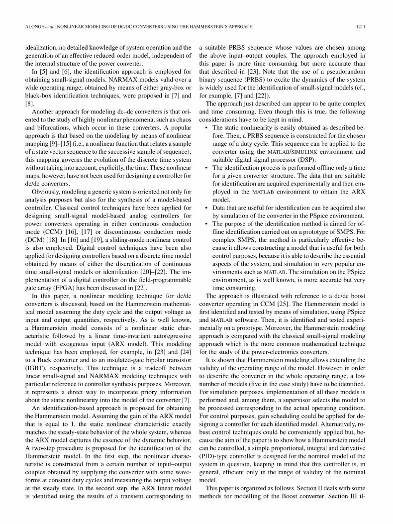
Fig. 1. Basic scheme of the boost converter.
lustrates the identification method of the Hammerstein model,its validation, and the comparison of Hammerstein and small-signal model approaches; simulation results, obtained by usingMATLAB and PSpice software, and experimental results aredisplayed. Section IV describes the design of a model-baseddiscrete time PID controller, designed by means of the identi-fied model, and shows some simulation and experimental resultsobtained considering a closed-loop control system consisting ofa prototype of a Boost converter and the above PID controller.Finally, Section V deals with the conclusions.
II. MODELING OF THE DC/DC BOOST CONVERTER
A basic scheme of the dc/dc boost converter is given in Fig. 1.The output voltage of the converter is greater than the inputvoltage ; the static gain (i.e., the output to input voltage ratio)depends on the duty cycle of the PWM signal supplying themetal–oxide semiconductor field-effect transistor (MOSFET)which, as already stated, is the input variable of the converter.It is assumed that the values of the parameters of the converterare chosen so that it operates in CCM.
A. Small-Signal Modeling
As is well known, according to the circuit-oriented modelingapproach, a mathematical model of the boost can be constructedusing the state space averaging technique [2], assuming the pa-rameters have their nominal values. This technique practicallylinks each other with the linear and time-invariant mathemat-ical models which describe the converter in correspondence toits conduction configurations. Its validity is ensured if the basicfrequency of the PWM waveform, which controls the converter,is much higher than the natural frequencies of the converter inquestion.
The mathematical model obtained by the above technique isstill nonlinear. From this model, a linear- and time-invariantsmall-signal model can be derived by means of linearizationaround a well-defined operating point.
Another approach for modeling the boost converter is theparametric identification approach. This approach does not re-quire neither the knowledge of the values of the parameters northe a priori analysis of the conduction configurations of the con-verter. Assuming that the converter is input-to-state stable (ISS)so that open-loop identification can be affected, the approach inquestion is based on the following steps:Step 1) excitation of the dynamics of the system by means of
a suitable input signal (i.e., the duty cycle );Step 2) choice of a suitable structure of the mathematical
model of the system and identification of its param-eters so that the dynamics of Step 1) are recoveredby the model itself.
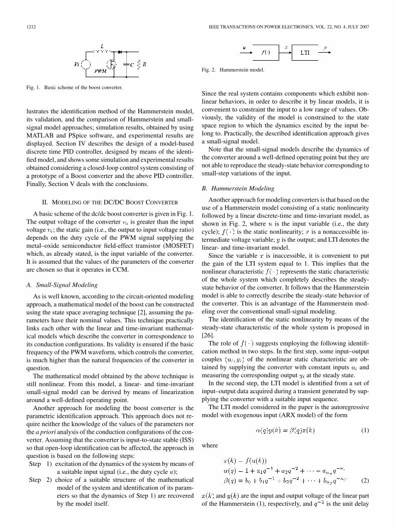
Fig. 2. Hammerstein model.
Since the real system contains components which exhibit non-linear behaviors, in order to describe it by linear models, it isconvenient to constraint the input to a low range of values. Ob-viously, the validity of the model is constrained to the statespace region to which the dynamics excited by the input be-long to. Practically, the described identification approach givesa small-signal model.
Note that the small-signal models describe the dynamics ofthe converter around a well-defined operating point but they arenot able to reproduce the steady-state behavior corresponding tosmall-step variations of the input.
B. Hammerstein Modeling
Another approach for modeling converters is that based on theuse of a Hammerstein model consisting of a static nonlinearityfollowed by a linear discrete-time and time-invariant model, asshown in Fig. 2, where is the input variable (i.e., the dutycycle); is the static nonlinearity; is a nonaccessible in-termediate voltage variable; is the output; and LTI denotes thelinear- and time-invariant model.
Since the variable is inaccessible, it is convenient to putthe gain of the LTI system equal to 1. This implies that thenonlinear characteristic represents the static characteristicof the whole system which completely describes the steady-state behavior of the converter. It follows that the Hammersteinmodel is able to correctly describe the steady-state behavior ofthe converter. This is an advantage of the Hammerstein mod-eling over the conventional small-signal modeling.
The identification of the static nonlinearity by means of thesteady-state characteristic of the whole system is proposed in[26].
The role of suggests employing the following identifi-cation method in two steps. In the first step, some input–outputcouples of the nonlinear static characteristic are ob-tained by supplying the converter with constant inputs andmeasuring the corresponding output at the steady state.
In the second step, the LTI model is identified from a set ofinput–output data acquired during a transient generated by sup-plying the converter with a suitable input sequence.
The LTI model considered in the paper is the autoregressivemodel with exogenous input (ARX model) of the form
(1)
where
(2)
and are the input and output voltage of the linear partof the Hammerstein (1), respectively, and is the unit delay
ALONGE et al.: NONLINEAR MODELING OF DC/DC CONVERTERS USING THE HAMMERSTEIN’S APPROACH 1213
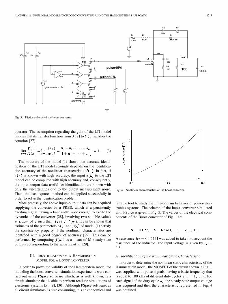
Fig. 3. PSpice scheme of the boost converter.
operator. The assumption regarding the gain of the LTI modelimplies that its transfer function from to satisfies theequation [27]
(3)
The structure of the model (1) shows that accurate identi-fication of the LTI model strongly depends on the identifica-tion accuracy of the nonlinear characteristic . In fact, if
is known with high accuracy, the input to the LTImodel can be computed with high accuracy and, consequently,the input–output data useful for identification are known withonly the uncertainties due to the output measurement noise.Then, the least-squares method can be applied successfully inorder to solve the identification problem.
More precisely, the above input–output data can be acquiredsupplying the converter by a PRBS, which is a persistentlyexciting signal having a bandwidth wide enough to excite thedynamics of the converter [28], involving two suitable values
of such that . It can be shown thatestimates of the parameters and of model (1) satisfythe consistency property if the nonlinear characteristics areidentified with a good degree of accuracy [29]. This can beperformed by computing as a mean of M steady-stateoutputs corresponding to the same input [29].
III. IDENTIFICATION OF A HAMMERSTEIN
MODEL FOR A BOOST CONVERTER
In order to prove the validity of the Hammerstein model formodeling the boost converter, simulation experiments were car-ried out using PSpice software which, as is well known, is acircuit simulator that is able to perform realistic simulations ofelectronic systems [5], [8], [30]. Although PSpice software, asall circuit simulators, is time consuming, it is an economical and
Fig. 4. Nonlinear characteristics of the boost converter.
reliable tool to study the time-domain behavior of power-elec-tronics systems. The scheme of the boost converter simulatedwith PSpice is given in Fig. 3. The values of the electrical com-ponents of the Boost converter of Fig. 1 are
A resistance was added to take into account theresistance of the inductor. The input voltage is given by
.
A. Identification of the Nonlinear Static Characteristic
In order to determine the nonlinear static characteristic of theHammerstein model, the MOSFET of the circuit shown in Fig. 1was supplied with pulse signals, having a basic frequency thatis equal to 100 kHz of different duty cycles . Foreach signal of the duty cycle , the steady-state output voltagewas acquired and then the characteristic represented in Fig. 4was obtained.
1214 IEEE TRANSACTIONS ON POWER ELECTRONICS, VOL. 22, NO. 4, JULY 2007
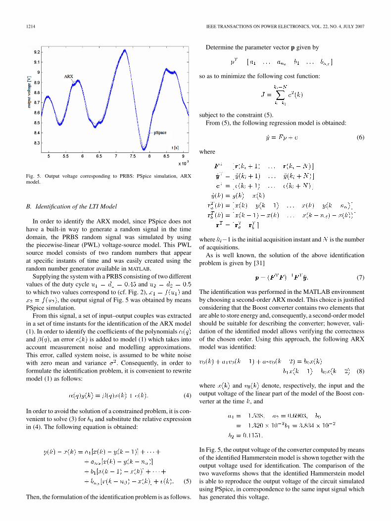
Fig. 5. Output voltage corresponding to PRBS: PSpice simulation, ARXmodel.
B. Identification of the LTI Model
In order to identify the ARX model, since PSpice does nothave a built-in way to generate a random signal in the timedomain, the PRBS random signal was simulated by usingthe piecewise-linear (PWL) voltage-source model. This PWLsource model consists of two random numbers that appearat specific instants of time and was easily created using therandom number generator available in MATLAB.
Supplying the system with a PRBS consisting of two differentvalues of the duty cycle andto which two values correspond to (cf. Fig. 2), and
, the output signal of Fig. 5 was obtained by meansPSpice simulation.
From this signal, a set of input–output couples was extractedin a set of time instants for the identification of the ARX model(1). In order to identify the coefficients of the polynomialsand , an error is added to model (1) which takes intoaccount measurement noise and modelling approximations.This error, called system noise, is assumed to be white noisewith zero mean and variance . Consequently, in order toformulate the identification problem, it is convenient to rewritemodel (1) as follows:
(4)
In order to avoid the solution of a constrained problem, it is con-venient to solve (3) for and substitute the relative expressionin (4). The following equation is obtained:
(5)
Then, the formulation of the identification problem is as follows.
Determine the parameter vector p given by
so as to minimize the following cost function:
subject to the constraint (5).From (5), the following regression model is obtained:
(6)
where
where is the initial acquisition instant and is the numberof acquisitions.
As is well known, the solution of the above identificationproblem is given by [31]
(7)
The identification was performed in the MATLAB environmentby choosing a second-order ARX model. This choice is justifiedconsidering that the Boost converter contains two elements thatare able to store energy and, consequently, a second-order modelshould be suitable for describing the converter; however, vali-dation of the identified model allows verifying the correctnessof the chosen order. Using this approach, the following ARXmodel was identified:
(8)
where and denote, respectively, the input and theoutput voltage of the linear part of the model of the Boost con-verter at the time , and
In Fig. 5, the output voltage of the converter computed by meansof the identified Hammerstein model is shown together with theoutput voltage used for identification. The comparison of thetwo waveforms shows that the identified Hammerstein modelis able to reproduce the output voltage of the circuit simulatedusing PSpice, in correspondence to the same input signal whichhas generated this voltage.

ALONGE et al.: NONLINEAR MODELING OF DC/DC CONVERTERS USING THE HAMMERSTEIN’S APPROACH 1215
Fig. 6. Responses relative to the step variation of the duty cycle from 0.3 to 0.55corresponding to ARX models identified by means of PRBS signals consistingof the two values of the duty cycle shown in the displayed legend.
C. Validation of the Model
In order to validate the Hammerstein model identified in theprevious subsection, another PRBS signal with the same valuesof the duty cycle and was applied to theboost converter; also in this case, the output voltage generatedby the circuit model in the PSpice environment is practicallysuperimposed to that generated by the identified Hammersteinmodel.
Successively, the behavior of the identified model was inves-tigated in a range of values of larger than that used for iden-tification. In particular, a step variation of the duty cycle from0.3 to 0.55 was applied to five Hammerstein models identifiedwith PRBS signals consisting of different couples of the dutycycle, beginning with a steady-state situation characterized froma duty cycle equal to 0.3. The corresponding results are given inFig. 6. Examination of Fig. 6 shows:
• all of the models give the same steady-state value indepen-dent of the PRBS used for identifying them;
• the transient behavior in terms of overshoot, rise time, andundershoot, depends on the duty cycle couple used for theidentification of the model.
It follows that it is convenient to consider some models iden-tified with different couples of the duty cycle if greater accu-racy is desired. This is shown in Fig. 7 where results are showncorresponding to two steps of the duty cycle from 0.45 to 0.50and from 0.50 to 0.55. These results were obtained using an ar-rangement in which five models appear identified using PRBSsignals constructed with the duty cycle couples (0.3,0.35), (0.35,0.40), (0.40,0.45), (0.45,0.50), and (0.50,0.55); a decision blockchooses the model to be processed according to the actual valueof the duty cycle.
D. Comparison of Hammerstein and Small-Signal Models
In order to compare the Hammerstein and the small-signalmodels, the last model has been identified using a PRBS se-
Fig. 7. Responses relative to two steps of the duty cycle from 0.45 to 0.50 andfrom 0.5 to 0.55 using the described arrangement consisting of five models.
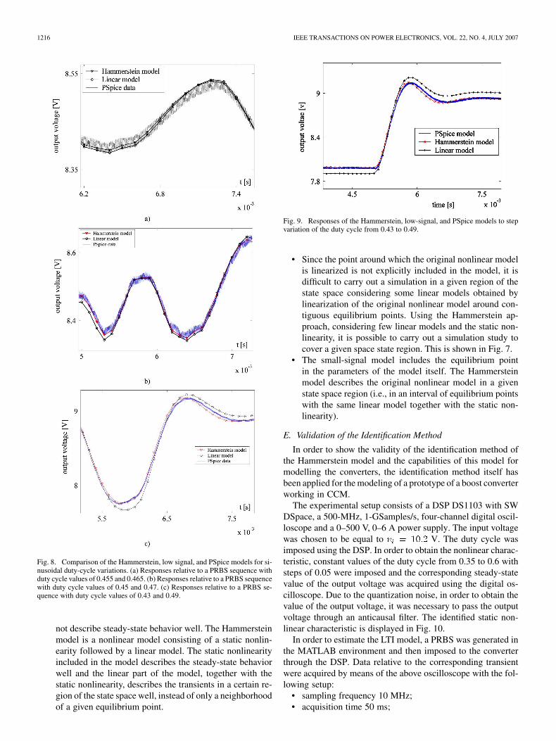
quence with values of the duty cycle equal to 0.455 and 0.465.The Hammerstein model tested is that identified considering thePRBS sequence with values of the duty cycle equal to 0.43 and0.49. Both models have been tested in three different supply sit-uations (i.e., with three PRBS sequences characterized by thefollowing three couples of the duty cycle: (0.455, 0.465), (0.45,0.47), and (0.43, 0.49). The results are given in Fig. 8(a)–(c).Examination of these figures shows that the Hammerstein modelallows better reproduction of the dynamic behavior of the con-verter in a range wider than that corresponding to the small-signal model. In fact, in the range of duty cycle [0.455, 0.465]and [0.45, 0.47], both models display practically the same be-havior (the Hammerstein model gives slightly better results),whereas in the range [0.43, 0.49], the output of the Hammer-stein model tracks the true output data much better than thesmall-signal model.
Another experiment was affected, supplying the above threemodels at a constant duty cycle up to 5 ms and thena step variation of the duty cycle from 0.43 to 0.49 was im-posed. The results are shown in Fig. 9, where the output voltagewaveforms given by the Hammerstein model, the small-signalmodel, and the PSpice model are displayed together. An exam-ination of Fig. 9 shows that the Hammerstein model is able toreproduce the static and the transient behaviors of the converterbetter than the small-signal model. The Hammerstein and thesmall-signal models capture the low-frequency behavior of theconverter whereas the PSpice model is able to also display theripple due to the high-frequency commutations.
The previous discussion shows that the principal differencesof low signal and Hammerstein modeling approaches are thefollowing.
• The small-signal approach is brought to a linear model, de-scribing the true nonlinear model in a little neighborhoodof a given equilibrium point, but this point does not ap-pear explicitly in the model but it is implicitly includedin the parameters of the linear model; as a consequence,the small-signal model sufficiently describes the transientsfor small signals around the equilibrium point but it does
1216 IEEE TRANSACTIONS ON POWER ELECTRONICS, VOL. 22, NO. 4, JULY 2007
Fig. 8. Comparison of the Hammerstein, low signal, and PSpice models for si-nusoidal duty-cycle variations. (a) Responses relative to a PRBS sequence withduty cycle values of 0.455 and 0.465. (b) Responses relative to a PRBS sequencewith duty cycle values of 0.45 and 0.47. (c) Responses relative to a PRBS se-quence with duty cycle values of 0.43 and 0.49.
not describe steady-state behavior well. The Hammersteinmodel is a nonlinear model consisting of a static nonlin-earity followed by a linear model. The static nonlinearityincluded in the model describes the steady-state behaviorwell and the linear part of the model, together with thestatic nonlinearity, describes the transients in a certain re-gion of the state space well, instead of only a neighborhoodof a given equilibrium point.
Fig. 9. Responses of the Hammerstein, low-signal, and PSpice models to stepvariation of the duty cycle from 0.43 to 0.49.
• Since the point around which the original nonlinear modelis linearized is not explicitly included in the model, it isdifficult to carry out a simulation in a given region of thestate space considering some linear models obtained bylinearization of the original nonlinear model around con-tiguous equilibrium points. Using the Hammerstein ap-proach, considering few linear models and the static non-linearity, it is possible to carry out a simulation study tocover a given space state region. This is shown in Fig. 7.
• The small-signal model includes the equilibrium pointin the parameters of the model itself. The Hammersteinmodel describes the original nonlinear model in a givenstate space region (i.e., in an interval of equilibrium pointswith the same linear model together with the static non-linearity).
E. Validation of the Identification Method
In order to show the validity of the identification method ofthe Hammerstein model and the capabilities of this model formodelling the converters, the identification method itself hasbeen applied for the modeling of a prototype of a boost converterworking in CCM.
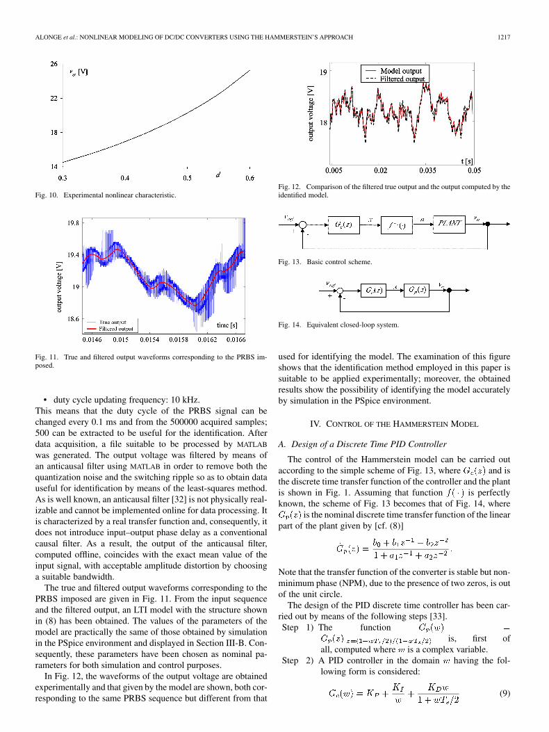
The experimental setup consists of a DSP DS1103 with SWDSpace, a 500-MHz, 1-GSamples/s, four-channel digital oscil-loscope and a 0–500 V, 0–6 A power supply. The input voltagewas chosen to be equal to V. The duty cycle wasimposed using the DSP. In order to obtain the nonlinear charac-teristic, constant values of the duty cycle from 0.35 to 0.6 withsteps of 0.05 were imposed and the corresponding steady-statevalue of the output voltage was acquired using the digital os-cilloscope. Due to the quantization noise, in order to obtain thevalue of the output voltage, it was necessary to pass the outputvoltage through an anticausal filter. The identified static non-linear characteristic is displayed in Fig. 10.
In order to estimate the LTI model, a PRBS was generated inthe MATLAB environment and then imposed to the converterthrough the DSP. Data relative to the corresponding transientwere acquired by means of the above oscilloscope with the fol-lowing setup:
• sampling frequency 10 MHz;• acquisition time 50 ms;
ALONGE et al.: NONLINEAR MODELING OF DC/DC CONVERTERS USING THE HAMMERSTEIN’S APPROACH 1217
Fig. 10. Experimental nonlinear characteristic.
Fig. 11. True and filtered output waveforms corresponding to the PRBS im-posed.
• duty cycle updating frequency: 10 kHz.This means that the duty cycle of the PRBS signal can bechanged every 0.1 ms and from the 500000 acquired samples;500 can be extracted to be useful for the identification. Afterdata acquisition, a file suitable to be processed by MATLAB
was generated. The output voltage was filtered by means ofan anticausal filter using MATLAB in order to remove both thequantization noise and the switching ripple so as to obtain datauseful for identification by means of the least-squares method.As is well known, an anticausal filter [32] is not physically real-izable and cannot be implemented online for data processing. Itis characterized by a real transfer function and, consequently, itdoes not introduce input–output phase delay as a conventionalcausal filter. As a result, the output of the anticausal filter,computed offline, coincides with the exact mean value of theinput signal, with acceptable amplitude distortion by choosinga suitable bandwidth.
The true and filtered output waveforms corresponding to thePRBS imposed are given in Fig. 11. From the input sequenceand the filtered output, an LTI model with the structure shownin (8) has been obtained. The values of the parameters of themodel are practically the same of those obtained by simulationin the PSpice environment and displayed in Section III-B. Con-sequently, these parameters have been chosen as nominal pa-rameters for both simulation and control purposes.
In Fig. 12, the waveforms of the output voltage are obtainedexperimentally and that given by the model are shown, both cor-responding to the same PRBS sequence but different from that
Fig. 12. Comparison of the filtered true output and the output computed by theidentified model.
Fig. 13. Basic control scheme.
Fig. 14. Equivalent closed-loop system.
used for identifying the model. The examination of this figureshows that the identification method employed in this paper issuitable to be applied experimentally; moreover, the obtainedresults show the possibility of identifying the model accuratelyby simulation in the PSpice environment.
IV. CONTROL OF THE HAMMERSTEIN MODEL
A. Design of a Discrete Time PID Controller
The control of the Hammerstein model can be carried outaccording to the simple scheme of Fig. 13, where and isthe discrete time transfer function of the controller and the plantis shown in Fig. 1. Assuming that function is perfectlyknown, the scheme of Fig. 13 becomes that of Fig. 14, where
is the nominal discrete time transfer function of the linearpart of the plant given by [cf. (8)]
Note that the transfer function of the converter is stable but non-minimum phase (NPM), due to the presence of two zeros, is outof the unit circle.
The design of the PID discrete time controller has been car-ried out by means of the following steps [33].Step 1) The function
is, first ofall, computed where is a complex variable.
Step 2) A PID controller in the domain having the fol-lowing form is considered:
(9)
1218 IEEE TRANSACTIONS ON POWER ELECTRONICS, VOL. 22, NO. 4, JULY 2007
where the term has been added so asand, consequently, can be physically
realizable.Step 3) The controller has been designed so that the
closed-loop system obtains a phase margin (rad)and a crossover frequency . The parameters ofthe controller, designed according to Steps 1)–3),satisfy the relationships
(10)
where
and is the phase of in rad. In the presentcase study
where is the frequency corresponding to. With the above requirements,
(10) becomes
(11)
From the first equation of (11), and imposing thatthe tracking error corresponding to a linear ramp isless than 5%, the following constraints on canbe established:
The parameter has been chosen by trial anderror.
B. Simulation Results
The controller has been tested by simulation in the MATLAB/SIMULINK environment, using the converter for the switchingmodel consisting of
when the mosfet is on
when the mosfet is off and in CCM
For a given input voltage , the output voltage varies from aminimum value and a maximum value , correspondingto, respectively, the minimum value of the duty cycle and themaximum value . Assuming , choosingand , is obtained. The nonlinear
Fig. 15. Closed-loop control scheme.
Fig. 16. Waveform of the inductor current.
Fig. 17. Tracking output error.
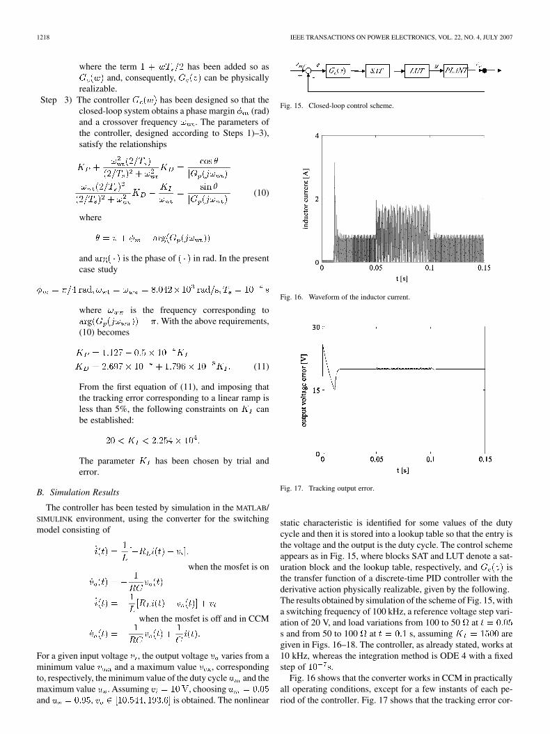
static characteristic is identified for some values of the dutycycle and then it is stored into a lookup table so that the entry isthe voltage and the output is the duty cycle. The control schemeappears as in Fig. 15, where blocks SAT and LUT denote a sat-uration block and the lookup table, respectively, and isthe transfer function of a discrete-time PID controller with thederivative action physically realizable, given by the following.The results obtained by simulation of the scheme of Fig. 15, witha switching frequency of 100 kHz, a reference voltage step vari-ation of 20 V, and load variations from 100 to 50 ats and from 50 to 100 at s, assuming aregiven in Figs. 16–18. The controller, as already stated, works at10 kHz, whereas the integration method is ODE 4 with a fixedstep of .
Fig. 16 shows that the converter works in CCM in practicallyall operating conditions, except for a few instants of each pe-riod of the controller. Fig. 17 shows that the tracking error cor-

ALONGE et al.: NONLINEAR MODELING OF DC/DC CONVERTERS USING THE HAMMERSTEIN’S APPROACH 1219
Fig. 18. Tracking error during a load variation of 50%.
Fig. 19. Input voltage. Reference step variation from 15 to 17 V.
responding to a step variation of the reference voltage gets highovershoot and undershoot which can be reduced by employingan antiwindup control scheme. Fig. 18 shows the behavior of thesystem for sudden variation of the load from 100 to 50 andvice-versa.
C. Experimental Results
Considering that the experimental investigation is performedwith the aim of verifying the validity of Hammerstein mod-eling for analysis and control purposes, experimental resultshave been obtained using a rapid prototyping system based onthe microcontroller DS 1103 which generates the switching fre-quency of 100 kHz, computes the duty cycle at a frequency of10 kHz, and acquires the data useful for processing the con-trol law and displaying the results. The results are given in Figs.19–24. In particular, Figs. 13–21 show the response of the con-trol system to a step variation of the reference voltage from 15to 17 V and Figs. 22–25 show the response of the control systemto a load step from 100 to 50 .
V. CONCLUSION
In this paper, with reference to a boost converter, the pos-sibility of describing the switching converters using Hammer-stein models consisting of a nonlinear static characteristic fol-
Fig. 20. Duty cycle. Reference step variation from 15 to 17 V.
Fig. 21. Output voltage. Reference step variation from 15 to 17 V.
Fig. 22. Zoom of output voltage. Reference step variation from 15 to 17 V.
lowed by an ARX model is shown. The two-steps approach em-ployed in this paper gives good results as it can be verified fromthe comparison of the behavior of the real system and that ofthe Hammerstein model. The method in question allows deter-mining the nonlinear characteristic with a good degree of ac-curacy and to obtain good estimates of the linear ARX model.However, it is shown that in order to describe the converter withhigh accuracy in a wide range of the duty cycle, it is convenient

1220 IEEE TRANSACTIONS ON POWER ELECTRONICS, VOL. 22, NO. 4, JULY 2007
Fig. 23. Duty cycle. Step variation of the load from 100 to 50 .
Fig. 24. Output voltage. Step variation of the load from 100 to 50 .
Fig. 25. Zoom of output voltage. Step variation of the load from 100 to 50 !.
to consider a low number of models, identified in contiguous in-tervals of the duty cycle itself and, for simulation purposes, todefine a suitable switching law which selects the model to beprocessed in the current operating condition. It is also shownthat the Hammerstein model is able to describe the converterin a range of the quantities involved that are wider than thatof small-signal models. An important feature of the Hammer-stein modeling approach is the independence of the steady-state
behavior from the range of values of the duty cycle in whichan ARX model is identified. This is due to the peculiarity ofthe Hammerstein models to capture the steady state and the dy-namics of a system by means of the static characteristic and theARX model, respectively. The Hammerstein model of the con-verter can be used for both the analysis and the design of a con-troller for the converter itself. The design of the controller canbe carried out in the following two approaches: 1) a controlleris designed for each model identified in a range of values ofthe duty cycle and the controller operating in a particular oper-ative situation is selected according to the gain scheduling tech-nique and 2) a robust controller is designed assuming that theconverter be described by a set of models, instead of only onemodel, to take parameter variations and unmodelled dynamicsinto account. In this paper, a simple discrete-time PID controllerhas been tuned on the identified Hammerstein model. Simula-tion and experiments on a prototype show that the performanceof the closed-loop control system is satisfactory.
REFERENCES
[1] S. Cuk, “Modelling, analysis and design of switching converters,”Ph.D. dissertation, Calif. Inst. Technol., Pasadena, CA, Dec. 1976,(Nasa Rep. CR-135174).
[2] R. D. Middlebrook and S. Cuk, “A general unified approach to model-ling switching converter power stages,” Int. J. Electron., vol. 42, no. 6,pp. 521–550, Jun. 1977.
[3] R. D. Middlebrook, “Small-signal modelling of pulse-width modu-lated switched-mode power converters,” Proc. IEEE, vol. 76, no. 4, pp.343–354, Apr. 1988.
[4] D. Maksimovic, A. M. Stancovic, V. J. Thottuvelil, and G. C. Verghese,“Modeling and simulation of power electronic converters,” Proc. IEEE,vol. 89, no. 6, pp. 898–912, Jun. 2001.
[5] J. Y. Choi, B. H. Cho, H. F. VanLandingham, H. S. Mok, and J. H.Song, “System identification of power converters based on a black-boxapproach,” IEEE Trans. Circuits Syst. I, Fundam. Theory Appl., vol.45, no. 11, pp. 1148–1158, Nov. 1998.
[6] B. Johansson and M. Lenells, “Possibilities of obtaining small-signalmodels of DC-DC power converters by means of system identification,”in Proc. 22nd Int. Telecommunications Energy Conf., INTELEC, Sep.2000, pp. 65–75.
[7] L. A. Aguirre, P. F. Donoso-Garcia, and R. Santos-Filho, “Use of apriori information in the identification of global nonlinear models—Acase study using a buck converter,” IEEE Trans. Circuits Syst. 1,Fundam. Theory Appl., vol. 47, no. 7, pp. 1081–1085, Jul. 2000.
[8] K. T. Chau and C. C. Chan, “Nonlinear identification of power elec-tronics systems,” in Proc. Int. Conf. Power Electronics and Drive Sys-tems, 1995, vol. 1, pp. 329–334.
[9] I. Zafrany and S. Ben-Yaakov, “A chaos model of subarmonic oscilla-tions in current mode PWM boost converters,” Proc. 26th Annu. IEEEPower Electronic Specialists Conf., vol. 2, pp. 1111–1117, Jun. 18–25,1995.
[10] S. Banerjee, E. Ott, J. A. Yorke, and G. H. Yuan, “Anomalous bifur-cations in dc-dc converters: Borderline collisions in piecewise smoothmaps,” Proc. 28th Annu. IEEE Power Electronic Specialists Conf., vol.2, pp. 1337–1344, Jun. 22–27, 1997.
[11] D. C. Hamill, J. B. Deane, and D. J. Jefferies, “Modelling of chaoticDC–DC converters by iterated nonlinear mappings,” IEEE Trans.Power Electron., vol. 7, no. 1, pp. 25–36, Jan. 1992.
[12] G. Yuan, S. Banerjee, E. Ott, and J. A. Yorke, “Border-collision bifur-cations in the buck converter,” IEEE Trans. Circuits Syst. I, Fundam.Theory Appl., vol. 45, no. 7, pp. 707–716, Jul. 1998.
[13] M. Di bernardo, F. Garofalo, L. Glielmo, and F. Vasca, “Switching,bifurcations, and chaos in DC/DC converters,” IEEE Trans. CircuitsSyst. I, Fundam. Theory Appl., vol. 45, no. 2, pp. 133–141, Feb. 1998.
[14] S. K. Mazumder, A. H. Nayfet, and D. Boroyevich, “Theoretical andexperimental investigation of the fast- and slow-scale instabilities of aDC–DC converter,” IEEE Trans. Power Electron., vol. 16, no. 2, pp.201–216, Mar. 2001.

ALONGE et al.: NONLINEAR MODELING OF DC/DC CONVERTERS USING THE HAMMERSTEIN’S APPROACH 1221
[15] S. K. Mazumder, A. H. Nayfet, and D. Boroyevich, “An investiga-tion into the fast- and slow-scale instabilities of a single phase bidi-rectional boost converter,” IEEE Trans. Power Electron., vol. 18, no. 4,pp. 1063–1069, Jul. 2003.
[16] J.-L. Lin and C.-H. Chang, “Small-signal modelling and control ofZVT-PWM boost converter,” IEEE Trans. Power Electron., vol. 18, no.1, pp. 2–10, Jan. 2003.
[17] Y. Panov and M. M. Jovanovic, “Small-signal analysis and controldesign of isolated power supplies with optocoupler feedback,” IEEETrans. Power Electron., vol. 20, no. 4, pp. 823–832, Jul. 2005.
[18] C. K. Tse and K. M. Adams, “Qualitative analysis and control of aDC-to-DC boost converter operating in diacontinuous mode,” IEEETrans. Power Electron., vol. 5, no. 3, pp. 323–330, Jul. 1990.
[19] E. Fossas, L. Martinez, and J. Ordinas, “Sliding mode control reducesaudiosusceptibility and load perturbation in the cuk converter,” IEEETrans. Circuits Syst. I, Fundam. Theory Appl., vol. 39, no. 10, pp.847–849, Oct. 1992.
[20] C. Rech, H. Pinheiro, A. Grundling, H. L. Hey, and J. R. Pinheiro,“Comparison of digital control techniques with repetitive integral ac-tion for low cost PWM inverters,” IEEE Trans. Power Electron., vol.18, no. 1, pp. 401–410, Jan. 2003.
[21] A. Borisavljevic, M. R. Iravani, and S. B. Dewan, “Modelling and anal-ysis of a digitally controlled high power switch-mode rectifier,” IEEETrans. Power Electron., vol. 20, no. 2, pp. 378–394, Mar. 2005.
[22] B. Miao, R. Zane, and D. Maksimovic, “System identification of powerconverters with digital control through cross-correlation methods,”IEEE Trans. Power Electron., vol. 20, no. 5, pp. 1093–1099, Sep.2005.
[23] A. Balestrino, A. Landi, M. Ould-Zmirli, and L. Sani, “Automaticnonlinear auto-tuning method for hammerstein modelling of electricaldrives,” IEEE Trans. Ind. Electron., vol. 48, no. 3, pp. 645–655, Jun.2001.
[24] J. T. Hsu and K. D. T. Ngo, “Behavioral modelling of the IGBT usingthe hammerstein configuration,” IEEE Trans. Power Electron., vol. 11,no. 6, pp. 746–754, Nov. 1996.
[25] F. Alonge, F. D’Ippolito, F. M. Raimondi, and S. Tumminaro, “Iden-tification of a hammerstein model for DC/DC converters operatingin CCM,” presented at the Power Eng. Soc. Conf./CIPS 2004 Conf.,Aachen, Germany, Jun. 20–25, 2004.
[26] R. Haber and L. Keviczky, “Nonlinear system identification-input-output modelling approach,” in Vol. 1: Nonlinear System ParameterIdentification. Norwell, MA: Kluwer, 1999.
[27] R. Iserman, Digital Control Systems. Berlin, Germany: Springer-Verlag, 1989, vol. I.
[28] T. Soderstrom and P. Stoica, System Identification. EnglewoodCliffs, NJ: Prentice-Hall, 1989.
[29] F. Alonge, F. D’Ippolito, F. M. Raimondi, and S. Tumminaro, “Iden-tification of nonlinear systems described by hammerstein models,” inProc. 42nd IEEE Conf. Decision and Control, Dec. 2003, vol. 4, pp.3990–3995.
[30] K. T. Chau, “A software tool for learning the dynamic behavior ofpower electronics circuits,” IEEE Trans. Educ., vol. 39, no. 1, pp.50–55, Feb. 1996.
[31] J. L. Cassidys and J. L. Junkins, Optimal Estimation of Dynamics Sys-tems. London, U.K.: Chapman & Hall, 2004.
[32] A. V. Oppenheim and R. W. Schafer, Discrete-Time Signal Pro-cessing. Englewood Cliffs, NJ: Prentice-Hall, 1989.
[33] C. L. Phillips and H. T. Nagle, Digital Control Systems. Analysis andDesign. Englewood Cliffs, NJ: Prentice-Hall, 1995.
Francesco Alonge (M’02) was born in Agrigento,Italy, in 1946. He received the Laurea degree in elec-tronic engineering from the University of Palermo,Palermo, Italy, in 1972.
Currently, he is a Full Professor of Automatic Con-trol in the Department of Systems and Control Engi-neering with the University of Palermo. His researchtopics include electrical drive control (including alsolinear and nonlinear observers, stochastic observers,parametric identification), robot control, parametricidentification and control in power electronics, and
UAV motion control in aeronautics.
Filippo D’Ippolito (M’00) was born in Palermo,Italy, in 1966. He received the Laurea degree in elec-tronic engineering from the University of Palermo,Palermo, Italy, in 1991, and the Research Doctoratedegree in systems and control engineering from theUniversity of Palermo in 1996.
Currently, he is a Research Associate in the De-partment of Systems and Control Engineering at theUniversity of Palermo. His research interests includecontrol of electrical drives, adaptive and visual/forcecontrol of robot manipulators, and control of elec-
trical power converters.Dr. D’Ippolito received the 2000 Kelvin Premium from the Institution of
Electrical Engineers (IEE), for the paper “Parameter identification of inductionmotor model using genetic algorithms.”
Francesco Maria Raimondi was born in Palermo,Italy, on April 16, 1969. He received the ElectricalEngineering degree in industrial automation systems(Hons.) and the Ph.D. degree in control engineeringfrom the University of Palermo, Palermo, in 1993 and1998, respectively.
Since 1999, he has been teaching a course on in-dustrial automation and since 2002 a course on Foun-dation of Automatic Control. His research interestsinclude diffusion modeling and the control of pollu-tants and acquisition systems of meteorological and
pollutants, motion control of electrical autonomous vehicles with sensor data fu-sion, and identification methods of nonlinear systems and control systems man-aged by industrial controllers (PLC).
Salvatore Tumminaro was born in Marianopoli,Caltanissetta, Italy, in 1970. He received the M.S.degree in electronic engineering and the Ph.D.degree in automation and system engineering fromthe University of Palermo, Palermo, Italy, in 2000and 2005, respectively.
In 2001, he joined STMicroelectronics, Catania,Italy, as an Integrated Circuit Designer for industrialand converter applications. Currently, he is a De-sign Team Leader of Integrated Circuits for ac–dcconverters. He has published some papers in system
modeling and power management, and holds one patent.


