0310p AFS WALL SYSTEMS in concrete combined and Delete functions of your word ... • Either fully...
32
03 STRUCTURE 0310p AFS WALL SYSTEMS in concrete combined © NATSPEC (Oct 14) 1 "[Insert date]" 0310P AFS WALL SYSTEMS IN CONCRETE COMBINED Branded worksection This branded worksection Template has been developed by NATSPEC in conjunction with AFS Systems Pty Ltd ® and may be used whilst the Product Partner is licensed to distribute it. The copyright remains with NATSPEC. As with all NATSPEC worksections, it is the responsibility of the user to make sure it is completed appropriately for the project. The user should also review its applicability for local conditions and regulations. Check www.natspec.com.au for the latest updated version. Worksection application This branded worksection Template is applicable to the use of concrete for building and associated structures together with specialist permanent formwork system products by AFS for external and internal concrete walls. It combines relevant clauses from the following worksections: Concrete formwork, Concrete reinforcement, Concrete post-tensioned, Concrete in situ and Concrete finishes. Guidance text All text within these boxes is provided as guidance for developing this worksection and should not form part of the final specification. This Guidance text may be hidden or deleted from the document using the NATSPEC Toolbar or the hidden text Hide and Delete functions of your word processing system. For additional information visit FAQs at www.natspec.com.au. Optional text Text in this font (blue with a grey background) covers items specified less frequently. It is provided for incorporation into Open text where it is applicable to a project. Related material located elsewhere in NATSPEC If a listed worksection is not part of your subscription package and you wish to purchase it, contact NATSPEC. Related material may be found in other worksections. See for example: • Concrete formwork. • Concrete reinforcement. • Concrete post-tensioned. • Concrete in situ. • Concrete finishes. • Shotcrete. • Cementitious toppings. • Terrazzo in situ. Cross references Worksections that cross reference this worksection are: • None. Material not provided by Product Partner This worksection includes generic material which may not be provided by AFS Systems Pty Ltd ® . Documenting this and related work You may document this and related work as follows: • Either fully detail the work in the structural drawings or define performance criteria (loading, deflection, exposure, fire- resistance) for any anticipated contractor design. For design by contractor, independent certification by a professional engineer of the design and documentation, and of the erected structure/structural element, is appropriate. • Show on the drawings any special requirements. • Refer to NATSPEC TECHnote DES 006 on specifying concrete. • See AS 2870, SAA HB 28 and CCAA T49 for design and construction requirements for residential slabs and footings. BCA 3.2.4 contains a table of site classifications that are the basis for requirements for footing design. Show the details on the drawings. Slabs on ground may be used as part of a termite management system installation – coordinate with the Termite management worksection. • Refer to CCAA Briefing 18 for information on design of concrete slabs for housing in flood-prone areas. • This worksection contains text that may be adapted for use in design and construct projects. Specifying ESD Refer to the NATSPEC TECHreport TR 01 on specifying ESD. The following may be specified in the worksection: • Thermal mass and embodied energy. Refer to AIA EDG DES 4, AIA EDG PRO 2 and AIA EDG 71 RC.
Transcript of 0310p AFS WALL SYSTEMS in concrete combined and Delete functions of your word ... • Either fully...

03 STRUCTURE 0310p AFS WALL SYSTEMS in concrete combined
© NATSPEC (Oct 14) 1 "[Insert date]"
0310P AFS WALL SYSTEMS IN CONCRETE COMBINED
Branded worksection This branded worksection Template has been developed by NATSPEC in conjunction with AFS Systems Pty Ltd® and may be used whilst the Product Partner is licensed to distribute it. The copyright remains with NATSPEC. As with all NATSPEC worksections, it is the responsibility of the user to make sure it is completed appropriately for the project. The user should also review its applicability for local conditions and regulations. Check www.natspec.com.au for the latest updated version.
Worksection application
This branded worksection Template is applicable to the use of concrete for building and associated structures together with specialist permanent formwork system products by AFS for external and internal concrete walls. It combines relevant clauses from the following worksections: Concrete formwork, Concrete reinforcement, Concrete post-tensioned, Concrete in situ and Concrete finishes.
Guidance text All text within these boxes is provided as guidance for developing this worksection and should not form part of the final specification. This Guidance text may be hidden or deleted from the document using the NATSPEC Toolbar or the hidden text Hide and Delete functions of your word processing system. For additional information visit FAQs at www.natspec.com.au.
Optional text Text in this font (blue with a grey background) covers items specified less frequently. It is provided for incorporation into Open text where it is applicable to a project.
Related material located elsewhere in NATSPEC
If a listed worksection is not part of your subscription package and you wish to purchase it, contact NATSPEC.
Related material may be found in other worksections. See for example:
• Concrete formwork.
• Concrete reinforcement.
• Concrete post-tensioned.
• Concrete in situ.
• Concrete finishes.
• Shotcrete.
• Cementitious toppings.
• Terrazzo in situ.
Cross references
Worksections that cross reference this worksection are:
• None.
Material not provided by Product Partner
This worksection includes generic material which may not be provided by AFS Systems Pty Ltd®.
Documenting this and related work You may document this and related work as follows:
• Either fully detail the work in the structural drawings or define performance criteria (loading, deflection, exposure, fire-resistance) for any anticipated contractor design. For design by contractor, independent certification by a professional engineer of the design and documentation, and of the erected structure/structural element, is appropriate.
• Show on the drawings any special requirements.
• Refer to NATSPEC TECHnote DES 006 on specifying concrete.
• See AS 2870, SAA HB 28 and CCAA T49 for design and construction requirements for residential slabs and footings. BCA 3.2.4 contains a table of site classifications that are the basis for requirements for footing design. Show the details on the drawings. Slabs on ground may be used as part of a termite management system installation – coordinate with the Termite management worksection.
• Refer to CCAA Briefing 18 for information on design of concrete slabs for housing in flood-prone areas.
• This worksection contains text that may be adapted for use in design and construct projects.
Specifying ESD
Refer to the NATSPEC TECHreport TR 01 on specifying ESD. The following may be specified in the worksection:
• Thermal mass and embodied energy. Refer to AIA EDG DES 4, AIA EDG PRO 2 and AIA EDG 71 RC.

03 STRUCTURE 0310p AFS WALL SYSTEMS in concrete combined
© NATSPEC (Oct 14) 2 "[Insert date]"
• Climate-responsive house design using concrete. Refer to CCAA T58.
• Concrete manufactured using a combination of coarse recycled and conventional aggregates and fine sand. Refer to SAA HB 155.
• Sustainable concrete buildings. Refer to CCAA Briefing 13.
• Sustainable concrete materials. Refer to CCAA Briefing 11.
• Thermal mass benefits for housing. Refer to CCAA Briefing 12.
• See the NP PCH (Precast concrete handbook) for sustainability design strategy’s such as the use of hollow core floor planks as ducting system to channel air around the building.
• Advantages for fire-resistance, panel re-use, formwork re-use and load bearing panels.
1 GENERAL
AFS Systems Pty Ltd® has over 18 years experience in supplying the construction industry with proprietary wall and framing systems. During this time AFS quickly earned a reputation for the manufacture and supply of innovative, permanent formwork walling solutions. So much so that CSR, the name behind some of the market’s most trusted and recognised brands chose to acquire AFS.
To date AFS has completed in excess of 1,000 projects, including 30,000 multi-residential units, solidifying its position as a leading supplier of permanent formwork wall solutions.
Whether it be a builder, developer, architect or engineer AFS has earned a reputation throughout Australia and abroad for supplying innovative walling solutions coupled with a genuine commitment to service excellence.
1.1 RESPONSIBILITIES
General Requirement: Provide cast concrete, as documented and as follows: - Conforming to the design details and performance criteria. - Satisfying quality and inspection requirements. - Compatible with documented finishes. Documented is defined in the General requirements worksection as meaning contained in the contract documents.
It is the designer’s responsibility to select surface finish methods that are compatible with the requirements of floor finishes applied over concrete.
AFS: Provide AFS LOGICWALL® and AFS REDIWALL® systems, as documented. Design This worksection can be used to document a variety of design and construct approaches. For example:
• Full design and construct: The contractor designs the whole of the project.
• Partial design and construct: The documents show some design details and all the design parameters for the project.
If the design, or completion of the design, is not the responsibility of the contractor, delete the subclause.
Designer: [complete/delete] Nominate the designer e.g. Registered architect, Professional engineer, Equipment supplier.
Authority requirements: [complete/delete] In particular, draw attention to any specific requirements of the DA and other regulatory bodies. Consider attaching DA conditions, if appropriate. Nominate if any part of the design is a BCA alternative solution.
Formwork: The design of formwork is the contractor’s responsibility, other than profiled steel sheeting composite formwork, standard AFS braces and AFS LOGICWALL® and AFS REDIWALL® panels. Allow for dimensional changes, deflections and cambers resulting from the following: - Imposed actions. - Concrete shrinkage and creep. - Temperature changes. - The application of prestressing forces (if any). This applies to all formwork types, including conventional, proprietary (non composite profiled steel sheeting) or purpose-made formwork.
Structural design: To AS 3600. AFS LOGICWALL®: To AS 3600.

03 STRUCTURE 0310p AFS WALL SYSTEMS in concrete combined
© NATSPEC (Oct 14) 3 "[Insert date]"
AFS REDIWALL®: To AS 3600. Post-tensioning: To AS 3600. Requirements in addition to AS 3600: [complete/delete] See AS 3600 Section 2 and AS 3600 Section 3 on design procedures and material properties and AS 3600 Section 4 on design for durability.
Delete if the work is fully documented in the contract documents.
1.2 COMPANY CONTACTS
AFS technical contacts Website: Go to www.afswall.com.au and follow the Contact Us tab.
1.3 CROSS REFERENCES
General Requirement: Conform to the following worksection(s): - General requirements. The General requirements worksection contains umbrella requirements for all building and services worksections.
- [complete/delete] List the worksections cross referenced by this worksection. The General requirements worksection references the Common requirements subgroup of worksections. It is not necessary to repeat them here. However, you may also wish to direct the contractor to other worksections where there may be work that is closely associated with this work.
NATSPEC uses generic worksection titles, whether or not there are branded equivalents. If you use a branded worksection, change the cross reference here.
See Related material located elsewhere in NATSPEC in the introduction Guidance.
1.4 STANDARDS
General Formwork design and construction, formed surfaces: To AS 3610 and AS 3610.1. Plywood formwork: To AS 6669. AFS: To the following standards: - Steel stud frames: To AS 1397. - Reinforced concrete: To AS 3600. - Fibre cement sheeting: To AS/NZS 2908.2. Profiled steel sheeting, including shear connectors: To AS 2327.1. Specification and supply of concrete: To AS 1379. Reinforced concrete construction: To AS 3600. SAA HB 71 provides guidance on concrete design to AS 3600, and is jointly published with the Cement and Concrete Association of Australia. SAA HB 64 and SAA HB 67 (both joint publications with Cement and Concrete Association of Australia) give guidance to good practice in concrete activities on building sites. SAA HB 84 gives guidance on concrete repair and protection. CIA Z13 provides performance criteria for concrete in marine environments. On fibres in concrete, see CIA CPN35. Concrete is deemed-to-satisfy to the BCA requirements for fire hazard properties (see BCA C1.10). For super-workable concrete refer to CIA Z40.
Residential ground slabs and footings: To AS 2870. Post-tensioning: To AS 3600. Concrete structures for retaining liquids: To AS 3735. For concrete structures retaining liquids, AS 3735 and AS 3735 Supp 1 supplement and take precedence over the requirements of AS 3600. For watertight concrete structures refer to CIA CPN28.
Strand, bar and wire: To AS/NZS 4672.1. Delete standards not applicable to the works.

03 STRUCTURE 0310p AFS WALL SYSTEMS in concrete combined
© NATSPEC (Oct 14) 4 "[Insert date]"
1.5 MANUFACTURER'S DOCUMENTS
Technical manuals Data and technical manuals: Visit www.afswall.com.au to login to the AFS Design Toolbox or order a free CD or hard copy of the AFS LOGICWALL® Designer Manual and AFS REDIWALL® Technical Guide.
1.6 INTERPRETATION
Definitions General: For the purposes of this worksection the following definitions apply: - AFS LOGICWALL®: Fire and acoustic rated permanent formwork system for concrete walling for
external and internal walls. - AFS REDIWALL®: Polymer based permanent formwork system for concrete walling for external and
internal walls. - Ambient temperature: The air temperature at the time of mixing and placing of concrete. - Anti-burst reinforcement: Reinforcement cage surrounding anchorages to control the tensile bursting
stresses. - Average ambient temperature: Average value of the daily maximum and minimum ambient
temperatures over the relevant period at a site. - Batch: A quantity of concrete containing a fixed quantity of ingredients and produced in a discrete
operation. - Concrete class:
. Normal: Concrete which is specified primarily by a standard compressive strength grade and otherwise in conformance with AS 1379 clause 1.5.3.
. Special: Concrete which is specified to have certain properties or characteristics different from, or additional to, those of normal-class concrete and otherwise in conformance with AS 1379 clause 1.5.4.
If special class concrete is documented for the project, document the relevant parameters in the Concrete properties schedule – performance.
- Early age strength: A mean compressive strength at 7 days exceeding the values shown in AS 1379 Table 1.2.
- Formwork: . Jump formwork: Incrementally moved formwork. . Lost formwork: Sacrificial formwork left in place. . Slip formwork: Continuously slipped or moving formwork. . Table forms: Prefabricated and re-usable formwork systems for slabs and beams.
- Green concrete: Concrete which has set but not appreciably hardened. - Production assessment: An assessment procedure for concrete specified by strength grade, carried
out by the supplier on concrete produced by a specific supplying plant and based on the statistical assessment of standard compressive strength tests on concrete.
- Project assessment: An assessment procedure for concrete specified by strength grade, specified at the customer’s option, which provides additional test data for the statistical assessment of concrete supplied to a specific project.
- Sample: A physical example that illustrates workmanship, materials or equipment, and establishes standards by which the work will be judged. It includes samples, prototypes and sample panels.
- Specimen: A portion of a sample which is submitted for testing. - Weather:
. Cold: Ambient shade temperature less than 10°C.
. Hot: Ambient shade temperature greater than 30°C. Edit the Definitions subclause to suit the project or delete, if not required. List alphabetically.
1.7 INSPECTION
Notice Inspection: Give notice so that inspection may be made of the following:

03 STRUCTURE 0310p AFS WALL SYSTEMS in concrete combined
© NATSPEC (Oct 14) 5 "[Insert date]"
- Base or subgrade before covering. - Membrane or film underlay installed on the base or subgrade. - Completed formwork and reinforcement, tendons, cores, fixings and embedded items fixed in place. - Used formwork, after cleaning and before re-use. - Concealed surfaces or elements before covering. - Commencement of concrete placing. - Stripping single storey suspended work, if conformance with AS 3610.1 is not possible. - Commencement of initial, incremental or final stressing of tendons. - Cutting and grouting tendons. - Evaluation of the off-form finishes. - Evaluation of surface finish. Amend to suit the project, adding critical stage inspections required.
Hold points, if required, should be inserted here. Consider including the following Optional text, as appropriate:
Hold points General: - Approval of proposed post-tensioning system tested to AS/NZS 1314, before work begins. - Approval of actual post-tensioning extensions, before tendons are cut off or made inaccessible for stressing.
Approval of the proposed post-tensioning system is essential to make sure anchorages meet AS/NZS 1314, before work begins. Comparison of theoretical and actual extensions is a fundamental quality assurance requirement for virtually all post-tensioning. To allow tendons to be re-stressed and/or de-stressed and/or tendon force re-verified, tendons should not be cut off, or otherwise made inaccessible for stressing, until approved by the responsible party.
Post-tensioned steels are not weldable. After cutting off there is usually insufficient length to mechanically couple or to de-stress the tendon in a controlled manner.
Processing of extensions must be done promptly (within 24 hours of submission) to maintain integrity and credibility of the process and to avoid delays and additional costs.
Add the approving party and any approval time constraints, if known.
1.8 TOLERANCES
Formwork Plumb of elements > 8 m high: 1:1000. Plumb of elements ≤ 8 m high: To AS 3610.1. Position: Construct formwork so that finished concrete conforms to AS 3600 clause 17.5 and as documented in the Formwork dimensional deviation schedule. AS 3600 clause 17.5.2 states the limits beyond which the design rules of the standard no longer apply. They are not intended as building tolerances. More stringent tolerances may be suitable.
Reinforcement Fabrication and fixing: To AS 3600 clause 17.2. Reinforcement and tendon position: To AS 3600 clause 17.5.3. Finishes Formed surfaces quality of surface finish: To AS 3610.1 Table 3.3.2. Document surface finish class in the Formed surfaces finishes schedule.
Consider deleting for class 2 formwork. Delete for class 3-5 formwork.
Unformed surfaces flatness: To the Flatness tolerance class table, for the documented class of finish, using a straightedge placed anywhere on the surface in any direction. Flatness tolerance class table Class Measurement Maximum deviation (mm) A 2 m straightedge 4 B 3 m straightedge 6 C 600 mm straightedge 6

03 STRUCTURE 0310p AFS WALL SYSTEMS in concrete combined
© NATSPEC (Oct 14) 6 "[Insert date]"
These classes have been adopted by NATSPEC in the absence of such in Australian Standards. It has been assumed that smoothness and projection tolerances form part of substrate preparation for the applicable floor finishes. The straightedge does not consider the frequency of surface undulations or waves. Consequently a Class B finish containing one wave under the straightedge may be more effective than a Class A finish with multiple waves.
For further information refer to the Cement Concrete Aggregates Australia CCAA Datasheet - CCAA Data Sheet Tolerances for Concrete Surfaces.
Typical applied finishes for each flatness tolerance class are:
• A: Resilient finishes.
• B: Unfinished (plantrooms), carpet, substrates for bituminous coatings.
• C: Floor tiles (scored finish).
Flatness tolerance class C is specifically stated for areas where the local flatness (600 mm) is not critical to the applied finishes. This varies from the minimum standard for flatness in AS 3600 clause 17.5.2.4.
AFS wall systems Position: Install AFS wall panels so that completed walls conform to AS 3600 clause 17.5. The surface finish for AFS wall panels does not need to be specified in the concrete worksection as the finish is provided by the external face of the wall panel. However, the final quality of the finished wall needs to be specified in later FINISH worksections in accordance with AS/NZS 2589.
1.9 SUBMISSIONS
Calculations If design or completion of design is the responsibility of the contractor add the following Optional text.
Design: Submit structural performance calculations. Formwork calculations: Submit calculations by a professional engineer experienced in formwork design to show that allowable concrete stresses will not be exceeded and formwork capability will be maintained for the following: - Proposed formwork procedures or loadings which differ from those documented. - Props above a floor that do not coincide with the props below. - Undocumented formwork shoring or stripping procedures or allowable loadings from stacked
materials. Post-tensioned calculations: Submit the following: - Calculations of tendon jacking forces, theoretical extensions and losses for each stressing stage. - Amount of draw-in expected in seating anchorages, friction along tendon (wobble) coefficient and
friction curvature coefficient for tendons and duct-forming material. Substantiating field data may also be required.
Certification Formwork design certification: For other than profiled steel sheeting composite formwork, submit certification by a professional engineer experienced in formwork design verifying conformance of the design. Formwork execution certification: Submit certification by a professional engineer experienced in formwork design and construction verifying conformance of the completed formwork, including the suitability of the formwork for the documented surface finish class. Post-tensioned concrete certification: Submit independent certification by professional engineer of the design and erected framing. Design Loading: Submit details of proposed construction systems, loads and procedures, including propping and re-shoring. Consider back propping delay times for appropriate structural element.
Execution details Moveable formwork: Provide the following details on the formwork drawings: - Table, slip and jump forms: Proposed method and sequence of moving the formwork to provide
concrete of the documented quality and surface finish. - Slip forms: The average rate of movement. Re-shoring: Submit details of any proposed re-shoring.

03 STRUCTURE 0310p AFS WALL SYSTEMS in concrete combined
© NATSPEC (Oct 14) 7 "[Insert date]"
Surface repair method: Submit details of any proposed surface repair method before starting repairs. Concrete: Submit proposals for mixing, placing, finishing and curing concrete including the following: - Changes to the concrete mix. - Curing and protection methods. - Curing period for low-pressure steam curing. - Cutting or displacing reinforcement, or cutting or coring hardened concrete. - Handling, placing, compaction and finishing methods and equipment, including pumping. - Placing under water. - Sequence and times for concrete placement, and construction joint locations and relocations. - Site storage, mixing and transport methods and equipment, if applicable. - Temperature control methods. - Sequence of concrete placement: Submit details of any proposed If sequential placement of slab
segments. - Sawn joints: Submit details of proposed methods, timing and sequence of sawing joints. Reinforcement: Submit the following: - General: Details of any proposed changes to documented reinforcement. - Damaged galvanizing: Details of proposed repair to AS/NZS 4680 Section 8. - Mechanical bar splices Details and test certificates for each size and type of bar to be spliced. - Provision for concrete placement: Details of spacing or cover to reinforcement that does not
conform to AS 3600. - Splicing: Details of any proposed changes to documented requirements. - Welding: Details of any proposed welding of reinforcement. Delete if welding is not acceptable.
AFS: Provide the following information: - If early removal of bracing is required, submit structural engineer’s approval in writing. Panels are
core-filled and supported by roof framing or floor above and removing braces prior to this or within 24 hours of pouring slab over, constitutes early removal of bracing.
- If AFS LOGICWALL® panels need to be cut on site for any reason, submit certification from AFS shop drawers prior to cutting. need to be cut on site for any reason, submit certification from AFS shop drawers prior to cutting.
Post-tensioning: Submit the following: - Details of the proposed post-tensioning system tested and certified to AS/NZS 1314, including
performance test certificates for each type and size of anchorage and coupler. - Safe work method statements including the name and contact details of the subcontractor. - Details of proposed gauging, stressing and grouting equipment and current calibration certificates
for tensioning and tension measuring equipment. - Concrete strength early age test results. - Calculated tendon extensions (theoretical extensions) at final stressing and for staged stressing if
required, before stressing operations begin. Pre-mixed supply delivery dockets: For each batch, submit a docket listing the information required by AS 1379, and the following: - For special class performance concrete: Documented performance and type of cement binder. - For special class prescription concrete: Details of mix, additives, and type of cement binder. - Method of placement and climate conditions during pour. - Name of concrete delivery supervisor. - Project assessment carried out each day. - The concrete element or part of the works for which the concrete was ordered, and where it was
placed. - The total amount of water added at the plant and the maximum amount permitted to be added at the
site.

03 STRUCTURE 0310p AFS WALL SYSTEMS in concrete combined
© NATSPEC (Oct 14) 8 "[Insert date]"
Materials Product conformity: Submit current assessments of conformity, as appropriate, as follows: - Certificate of conformity by a JAS-ANZ accredited third party. e.g. Reinforcement: To AS/NZS 4671.
- Report by a NATA accredited laboratory describing tests and giving results which demonstrate that the product conforms.
Concrete mixes: Submit details, for each grade and type of concrete including any proposed use of special-purpose cement types. Curing compounds: Submit details of any proposed liquid membrane-forming curing compound, including the following: - Certified test results for water retention to AS 3799 Appendix B. It is likely that polyvinyl acetate (PVA-based) products will not conform to water retention requirements, refer AS 3799 Informative Appendix D clause D5.5.2.
- Evidence of compatibility with concrete, and with applied finishes including toppings and render, if any, including methods of obtaining the required adhesion.
- For visually important surfaces, evidence that an acceptable final surface colour will be obtained. Admixtures: Submit details of any proposed admixtures, including the following: - Brand name. - Place of manufacture. - Basic chemical composition. Admixtures must not be corrosive to steel and must not encourage other detrimental effects such as cracking and spalling.
Void formers: Use void formers tested under laboratory conditions. Place formers on damp sand and load with a mass of wet concrete at least equal to the mass of the beams or slabs to be supported. Submit certified test results to verify conformance with the following requirements: - Deflection during placing and compaction of the concrete does not exceed beam or slab span/1000. - Additional deflection between initial set and 7 days does not exceed span/400. - Collapse and loss of load carrying capacity occurs not more than 48 hours after flooding with water,
creating a void at least 60% of the original depth of the void former. Reinforcement strength and ductility: Submit type-test reports to verify conformance to AS 3600 Table 3.2.1 for each reinforcement type. Post tensioning: Submit the following: - Grout: Proposed grout mix and certified test results (including grading, proportions, compressive
strength, shrinkage and additives, if any). - Epoxy grout: If required, proposed formulation. - Duct-forming material: Samples of proposed material. - Prestressing steel: Test certificates to AS/NZS 4672.2 for every delivery of strand, bar or wire
proposed. AFS LOGICWALL®: Submit the following: - CSIRO test certificate for fire resistance, available by contacting AFS. AFS LOGICWALL panels have been subjected to a fire resistance test carried out by the CSIRO. This test ascertained the following Fire Resistance Levels (FRL):
• AFS 120 and AFS150 FRL = 240/240/180
• AFS162, AFS200 and AFS262 FRL = 240/240/240.
Refer to NATSPEC TECHnote DES 020 on fire behaviour of building materials and assemblies, for further information.
- Certification of acoustic performance, available by contacting AFS. AFS LOGICWALL walls have been extensively tested for acoustic performance both in the field and in the laboratory. The following results have been achieved with standard AFS LOGICWALL walls:
• AFS120 - RW = 50 Dnt,W+Ctr = 41-42
• AFS150 - RW = 52 Dnt,W+Ctr = 45-46
• AFS162 - RW = 52 Dnt,W+Ctr = 45-49
• AFS200 - RW = 55 Dnt,W+Ctr = 46-48

03 STRUCTURE 0310p AFS WALL SYSTEMS in concrete combined
© NATSPEC (Oct 14) 9 "[Insert date]"
• AFS262 - RW = 57 Dnt,W+Ctr = 48-50
Records Post-tensioned concrete: submit the following: - Post-tensioning record. - Post-tensioning stressing schedule. - Post-tensioning grouting record. Samples Coloured concrete: Submit sample blocks of coloured concrete produced using the proposed mix and method before casting final concrete as follows: - Number: 4. - Size (nominal): 300 x 300 x 50 mm. Shop drawings Cores, fixings and embedded items: Submit the proposed locations, clearances and cover and show any proposed repositioning of reinforcement. AFS LOGICWALL® drawings: Submit shop drawings of the AFS LOGICWALL® works before starting on site, showing details of the following: - Edge form detail. - Estimated m3 of concrete required for each wall. - Location of all penetrations. - Location of any cast in elements. - Panel dimensions. - Panel elevations. - Plan layout with wall numbers. - Slab set-downs along wall line. Shop drawings are not normally necessary for AFS REDIWALL®. If necessary, detail the requirements of the shop drawings here.
Formwork: Submit shop drawings including details of proposed linings, bolt positions, facings, release agents and, where applicable, re-use of formwork. Post-tensioned drawings: Submit shop drawings showing the following: - Profiles, sizes and details of tendons, tendon numbers, anchorages, ducts, duct formers, splicing,
sheathing, end block reinforcement and other associated components. - Stressing requirements including sequence of stressing, jacking forces and the basis of assumed
loss calculations. - Number, size and position of grout openings, vents and drain holes in the ducts. Subcontractors Pre-mixed supply: Submit names and contact details of proposed pre-mixed concrete suppliers and alternative source of supply in the event of breakdown of pre-mixed or site mixed supply. Delete if supplier/installer details are not required.
Tests The General requirements worksection covers tests in Definitions and calls for an inspection and testing plan under SUBMISSIONS, Tests.
Other tests: Submit results, as follows: - Site slip resistance test of completed installation to AS 4663. - Concrete compressive strength test results to AS 1012.9. Detail the tests required in PRODUCTS or EXECUTION, as appropriate, and list the submissions required here.

03 STRUCTURE 0310p AFS WALL SYSTEMS in concrete combined
© NATSPEC (Oct 14) 10 "[Insert date]"
2 PRODUCTS
2.1 GENERAL
Product substitution Other products: Conform to PRODUCTS, GENERAL, Substitutions in the General requirements worksection. The General requirements worksection clause sets out the submissions required if the contractor proposes alternative products.
Refer also to NATSPEC TECHnote GEN 006 for more information on proprietary specification.
2.2 AFS WALL SYSTEMS
General Visit www.afswall.com.au for more information. AFS LOGICWALL® and AFS REDIWALL® are permanent formwork systems for concrete walling for external and internal walls. It consists of lightweight sandwich panels created by bonding hard-wearing, fibre cement sheets to galvanized steel stud frames. The panels are quickly and simply hand erected on site and then core-filled with concrete to achieve load bearing walls that are fire and sound rated. The fibre cement sheeting remains in place as sacrificial formwork and provides an excellent substrate for applied finishes such as skim coating, acrylic render and paint.
Panel type Single reinforcement carriers: [complete/delete] Double reinforcement carriers: [complete/delete] The internal galvanized steel stud frame of the AFS LOGICWALL® panels and the internal webs of the AFS REDIWALL® panels allow for horizontal reinforcement to be placed centrally within the single reinforcement carrier product range and a layer in each face for the double reinforcement carrier range, both maintaining sufficient cover to the reinforcement in accordance with AS 3600. Available AFS product range:
Single reinforcement carriers:
• AFS120.
• AFS150.
• AFS162.
• AFS200.
• AFS REDIWALL® 150.
• AFS REDIWALL® 200.
Double reinforcement carriers:
• AFS200D.
• AFS262D.
• AFS REDIWALL® 200.
Select the products to be used above.
Sealant/Adhesive Polyurethane sealant/adhesive: [complete/delete] AFS recommend the use of polyurethane based sealant/adhesives such as Sikaflex or Bostik Seal’n’Flex. Select the chosen sealant above.
A double bead of sealant must be applied under the floor track of all walls.
Panel Braces General: Make sure that the AFS panels are suitably braced to maintain their integrity whilst core filling with concrete, in conformance with the methods set out in the AFS Designer Manual. Panel braces: Standard AFS braces. The standard AFS braces used by installers are a purpose manufactured adjustable brace, engineer certified and adequate for standard applications. In situations where panels higher than 3.6 m are being installed or on sites in areas known to be subject to adverse wind conditions, consider the use of alternative braces, specified and approved by a professional engineer.
2.3 MATERIALS
General Stockpile: If uniform, consistent colour is documented, stockpile sand, cement and aggregates.

03 STRUCTURE 0310p AFS WALL SYSTEMS in concrete combined
© NATSPEC (Oct 14) 11 "[Insert date]"
Aggregates Standard: To AS 2758.1. Aggregate properties: As documented in the Aggregate property schedule. Cement Standard: To AS 3972. If considering the use of geopolymer cement, refer to CIA Z16 for further information.
Age: Less than 6 months old. Storage: Store cement bags under cover and above ground. Water Standard: To AS 1379 clause 2.4. Requirement: Clean, free from oil, acid, alkali, organic or vegetable matter and including not more than 500 mg/l of chloride ions. Polymeric film underlay Vapour barriers and damp-proofing membranes: To AS 2870 clause 5.3.3. Chemical admixtures Standard: To AS 1478.1. Special purpose admixtures are covered in AS 1478.1 Informative Appendix B clause B11.
Curing compounds Curing compounds: To AS 3799.
2.4 CONCRETE
Properties Concrete mix and supply: Conform to the following: - AFS LOGICWALL®: Special-class to AS 1379 clause 1.5.4 and AFS LOGICWALL® Mix Design
detailed in the AFS LOGICWALL® - Designer Manual.
. Properties: As documented in the Concrete properties schedule - performance. Document the properties of special class concrete on the structural drawings or in the Concrete properties schedule - performance. Edit this subclause as appropriate.
- AFS REDIWALL®: Special-class to AS 1379 clause 1.5.4 and the concrete mix detailed in the AFS REDIWALL® Technical Guide.
- Normal-class: To AS 1379 clause 1.5.3. . Properties: As documented in the Concrete properties schedule - performance.
AS 1379 clause 1.5.3.2 basic parameters including strength grade, slump and aggregate size must be documented on the structural drawings or in the Concrete property schedule - performance.
- Special-class: To AS 1379 clause 1.5.4. . Properties: As documented in the Concrete properties schedule - performance.
Document the properties of special class concrete on the structural drawings or in the Concrete properties schedule - performance. Edit this subclause as appropriate.
Coloured concrete Standard: To AS 3610.1.
2.5 TESTING
General Test authority: Concrete supplier or NATA registered laboratory. Reports and records of test results: To the relevant parts of the AS 1012 series. Keep results on site. Assessment process of test results Standard: To AS 1379. Method of assessment: Project assessment.

03 STRUCTURE 0310p AFS WALL SYSTEMS in concrete combined
© NATSPEC (Oct 14) 12 "[Insert date]"
Consider changing the default to Production assessment, if satisfactory for the particular project. Document also the method of assessment in the Concrete properties schedule - performance. If the method of assessment is not documented, production assessment will be carried out by the concrete production plant.
Sampling Method of sampling: AS 1012.1. Sampling locations: To AS 1012.1 and the following: - Slump tests: On site, at the point of discharge from the agitator. - Compressive strength tests: Spread the site sampling evenly throughout the pour. Frequency of sampling: To AS 1379 Sections 5 and 6 and the following: - Slump tests: Take at least one sample from each batch. - Compressive strength tests: To the Project assessment strength grade sampling table. For project assessment, AS 1379 clause 6.5.2 requires one sample from each 50 m3 of concrete. For columns and load bearing walls one sample from each batch is recommended and for all other elements, sampling to the per day defaults of the Project assessment strength grade sampling table. The table default values are considered good practice but specifiers may amend the table to reflect the quality control and accepted level of risk they deem suitable for the project.
Project assessment strength grade sampling table Number of batches for each type and grade of concrete per day
Minimum number of samples: Columns and load bearing wall elements (per batch)
Minimum number of samples: Other elements (per day)
1 1 1 2-5 1 2 6-10 1 3 11-20 1 4 each additional 10 1 1 additional Making and curing of specimens General: To AS 1012.8.1 and AS 1012.8.2. Specimens for compressive strength tests: Make and cure at least two specimens from the sample of each grade. Specimen size: - Aggregate size ≤ 20 mm: Nominally 200 x 100 mm diameter. - Aggregate size > 20 mm: Nominally 300 x 150 mm diameter. Test methods General: To the relevant parts of the AS 1012 series. Acceptance criteria: - General: As documented in the Concrete properties schedule – performance. - Early age compressive strength: As documented in the Control tests schedule. Slump tests: Assess slump for every batch. Perform slump test on each strength sample. Drying shrinkage at 56 days: To AS 1012.13. For shrinkage sensitive structures the duration of air drying should be 56 days.
Embedded pressure pipes General: Complete leak tests before embedding pipes. Liquid retaining structures Testing for liquid tightness: To AS 3735.
2.6 FORMWORK
General Form linings, facings and release agents: Compatible with finishes applied to concrete. Lost formwork: Free of timber or chlorides, and not to impair the structural performance of the concrete members.

03 STRUCTURE 0310p AFS WALL SYSTEMS in concrete combined
© NATSPEC (Oct 14) 13 "[Insert date]"
Void formers: Material capable of maintaining rigidity and shape until the concrete has set, capable of withstanding construction loads and non-collapsible on absorption of moisture. Profiled steel sheeting composite formwork Material: Hot-dipped zinc-coated sheet steel to AS 1397. Minimum steel grade: G550. Amend if appropriate.
Zinc coating weight: [complete/delete] Nominate one of the two levels of protection offered by BlueScope Steel:
• Z350: 350 g/m2 zinc coating weight is recommended for use in non-aggressive areas.
• Z450: 450 g/m2 zinc coating weight is recommended for severe and aggressive environment where a build-up of airborne corrosive contaminants can affect the coating.
Make sure that the product documented has the level of galvanizing selected. Refer to NATSPEC TECHnote DES 010 on atmospheric corrosivity categories for ferrous products.
Accessories: Adopt material and corrosion protection to match the profiled steel sheeting. Plywood formwork Material: Plywood sheeting to AS 6669. AS 6669 does not cover off-form surface finish Class 1.
Grade: Use appropriate grade for the documented design dimensions, loading and surface quality Refer to AS 6669 for information on surface quality, veneer qualities, and stress grades.
Joints: Seal the joints consistent with the documented surface finish class. Tolerances: To AS 3610.1 Section 3. Document special requirements or dimensions.
2.7 REINFORCEMENT
Fibre reinforcement Standard: To CIA CPN35. Steel reinforcement See the ARC Reinforcement handbook 2012 for information on steel reinforcement.
Standard: To AS/NZS 4671. Shape: [complete/delete] R (round), D (deformed ribbed), I (deformed indented) or welded wire mesh.
Ductility class: [complete/delete] To AS/NZS 4671 clause 5.2(c): L (low), N (normal) or E (seismic).
Strength grade: [complete/delete] AS/NZS 4671 considers only 3 strength grades 250 MPa, 300 MPa and 500 MPa. See AS 3600 clause 17.2 for materials and construction requirements.
Surface condition: Free of loose mill scale, rust, oil, grease, mud or other material which would reduce the bond between the reinforcement and concrete. Protective coating Standard: To AS 3600 clause 17.2.1.2. Document any requirements for stainless steel reinforcement as this is not covered in AS 3600.
General: For concrete elements containing protective coated reinforcement, provide the same coating type to all that element’s reinforcement and embedded ferrous metal items, including tie wires, stools, spacers, stirrups, plates and ferrules, and protect other embedded metals with a suitable coating. Epoxy coating: High build, high solids, chemically resistant coating. - Thickness: 200 µm minimum. Galvanizing: To AS/NZS 4680, as follows: - Sequence: If fabricating after galvanizing, repair damaged galvanising and coat cut ends. - Zinc-coating (minimum): 600 g/m2.

03 STRUCTURE 0310p AFS WALL SYSTEMS in concrete combined
© NATSPEC (Oct 14) 14 "[Insert date]"
Consider whether passivation of the galvanizing needs to be documented. Refer to CIA CPN17 on the use of galvanized reinforcement in concrete to assess whether the default thickness is appropriate. Do not mix galvanized reinforcement with uncoated steel in an electrolyte (moisture) as adverse galvanic action can result.
Tie wire General: Annealed steel 1.25 mm diameter (minimum). External and corrosive applications: Galvanized.
2.8 POST-TENSIONING
Grout properties Standard: To AS 3600 clause 17.1.8. Maximum shrinkage: 1% by volume after 24 hours. Maximum water:cement ratio: 0.45 (by weight). Compressive strength: 32 MPa at 7 days. Grout mixes for post-tensioned tendon ducts are usually determined by the contractor. Performance and testing requirements, if any, may be documented here if not shown on the drawings. Test frequency is dependent on the size of the project.
Grout materials Fine aggregates: Do not use aggregates for post tensioning grout unless cross sectional area of ducts is 5 times the cross sectional area of the tendon. Aggregates are rarely used for grouting of post-tensioning.
Cement: To AS 3972 and free from calcium chloride and less than two months old. The use of GB cements for grouting is now accepted practice.
Admixtures: To AS 1478.1. Include an anti-bleed additive. Fly ash: To AS 3582.1 and proportioned according to early strength requirements. Water: To AS 1379. Clean, free from oil, acid, alkali, organic or vegetable matter and including not more than 500 mg/l of chloride ions. Epoxy grout type: Commercial epoxy formulation of compressive strength exceeding 40 MPa. Ducts Robustness: Provide ducts with sufficient strength to retain their shape, resist damage during construction, and prevent deterioration or electrolytic action by the entrance of cement paste or water from the concrete. Profile: [complete/delete] For example: Corrugated steel or plastic. Document here, or show on the drawings.
Wall thickness: To allow for abrasion during stressing of the tendon. Size: To allow feeding of tendons and grouting. Tendon material Prestressing steel: Type and grade of strand, wire or bar to AS/NZS 4672.1. Type: 7 wire, stress relieved, high tensile steel and strand. Show size designations, ductility, diameters on the drawings.
Quality: Make sure tendons have no nicks, damage or foreign matter such as mud and dirt. Inspect at delivery and store the prestressing steel on supports clear of the ground. Straightening of tendons: Not permitted. Supply tendons in coils large enough to self straighten. High tensile steel bars: Inspect individually and reject any bars with surface imperfections more than 0.40 mm deep. Other steel Anchor plates: Hot-dip galvanized to AS/NZS 4680. Anchorages: To AS/NZS 1314. Reinforcement: To AS/NZS 4671.

03 STRUCTURE 0310p AFS WALL SYSTEMS in concrete combined
© NATSPEC (Oct 14) 15 "[Insert date]"
2.9 MISCELLANEOUS
Surface hardeners, sealants and protectors Material supply: If required by the project documentation, provide proprietary products in conformance with the manufacturer’s written requirements. Slip resistance treatment Slip resistance classification: To AS 4586.
3 EXECUTION
3.1 POLYMERIC FILM UNDERLAY
Location General: Under slabs on ground, including integral ground beams and footings, provide a vapour barrier or, in areas prone to rising damp or salt attack, a damp-proofing membrane. Provision of a vapour barrier for external slabs on ground prevents water loss to the subgrade and has the potential to reduce slab curling at edges and corners.
AS 2870 Section 5.5 provides additional requirements and detailing of damp proof membranes for concrete slabs and footings exposed to either saline or acid sulphate soils. AS 2870 Section C5.5 and CCAA T56 provide information on concrete exposed to saline soils.
Base preparation General: Conforming to base type, as follows: - Concrete working base: Remove projections above the plane surface, and loose material. - Graded prepared subgrade: Blind with sufficient sand to create a smooth surface free from hard
projections. Wet the sand just before laying the underlay. Installation Standard: To AS 2870 clause 5.3.3. General: Lay underlay over the base as follows: - Lap joints at least 200 mm and seal the laps and penetrations with waterproof adhesive tape. - Face the laps away from the direction of concrete pour. - Continue up vertical faces past the damp-proof course where applicable, and tape fix at the top. - Patch or seal punctures or tears before placing concrete. - Cut back as required after concrete has gained strength and formwork has been removed.
3.2 FORMWORK
General Requirement: As documented in the Formed surface finishes schedule. Preparation Cleaning: Before placing concrete, remove free water, dust, debris and stains from the formwork and the formed space. Bolt holes Removable bolts: Remove tie bolts without causing the concrete. Formwork tie bolts left in the concrete: Position more than 50 mm from the finished surface. Bolt hole filling: Provide material with durability and colour matching the concrete. Recessed filling: Fill or plug the hole to 6 mm below the finished surface. Corners Work above ground: Chamfer at re-entrant angles, and fillet at corners. Face of bevel 25 mm. Embedments Fixing: Fix embedments through formwork to prevent movement, or loss of slurry or concrete, during concrete placement. Openings Inspection: In vertical formwork provide openings or removable panels for inspection and cleaning, at the base of columns, walls and deep beams.

03 STRUCTURE 0310p AFS WALL SYSTEMS in concrete combined
© NATSPEC (Oct 14) 16 "[Insert date]"
Access: For thin walls and columns, provide access panels for placing concrete. Release agents Application: Before placing reinforcement, apply a release agent to linings and facings. Slip formwork Provision for inspection: Provide access below the moveable formwork for surface treatment and inspection. Profiled steel sheeting composite formwork Fixing: If sheeting cannot be fixed to structural steel supports with puddle welds, or with welded shear studs in composite construction, provide details of proposed fixings. Steel linings Rust: Clean off any rust and apply rust inhibiting agent before re-use. Visually important surfaces Surface finish classes 1, 2 or 3: Set out the formwork to give a regular arrangement of panels, joints, bolt holes, and similar visible elements in the formed surface. Void formers Protection: Keep void formers dry until use, install on a firm level surface and place reinforcement and concrete with minimum delay.
3.3 AFS WALL SYSTEMS
Substrate Preparation Requirements: Concrete contractor must co-ordinate with AFS installer prior to placing concrete to determine concrete finish requirements at wall locations. Slab must be swept clean prior to installation of floor track for wall. AFS LOGICWALL® installation General: To AFS Designer Manual. Floor track: Sign off the setting out of the wall positions prior to fixing the floor track to the concrete slab. Sealant/Adhesive: Provide a double bead of polyurethane sealant/adhesive under the floor track of all external walls and any portion of wall that separates or adjoins wet-areas. Panel joints: Use polyurethane sealant/adhesive in conjunction with self tapping screws for fixing at each vertical panel joint and between panel and floor track. Braces: Fix to panel using 2-3 screws per brace. Make sure screws engage metal stud/joiner within panel. Fix to slab using proprietary screw style bolt, installed to manufacturer’s recommendations. Tolerance: Install to achieve an alignment of ± 4 mm over any 1.8 m vertical or horizontal plane. Reinforcement: Place reinforcement as documented. Concrete placement: To PLACING AND COMPACTION. AFS REDIWALL® installation General: To AFS Designer Manual. Floor track: Sign off the setting out of the wall positions prior to fixing the floor track to the concrete slab. Sealant/Adhesive: Provide a double bead of polyurethane sealant/adhesive under the floor track of all external walls and any portion of wall that separates or adjoins wet-areas. Braces: Brace securely by fixing to formwork deck or by fixing horizontal walling planks to face of panels and bracing diagonally to ground with timber bracing or standard AFS braces. Tolerance: Install to achieve an alignment of ± 4 mm over any 1.8 m vertical or horizontal plane. Reinforcement: Place reinforcement as documented. Concrete placement: To PLACING AND COMPACTION.
3.4 REINFORCEMENT
Dowels Fixing: If a dowel has an unpainted half, embed in the concrete placed first. Tolerances: - Alignment: 1:150.

03 STRUCTURE 0310p AFS WALL SYSTEMS in concrete combined
© NATSPEC (Oct 14) 17 "[Insert date]"
- Location: ± half the diameter of the dowel. Grade: 250 N. Amend this default if required.
Cover Concrete cover generally: To AS 3600 clause 4.10. Concrete cover for structures for retaining liquids: To AS 3735. Concrete cover for residential ground slabs and footings: To AS 2870. See AS 3735 Section 4 for durability exposure classification. Show concrete cover on the structural drawings.
Supports Proprietary concrete, metal or plastic supports: Provide chairs, spacers, stools, hangers and ties, as follows: - Able to withstand construction and traffic loads. - With a protective coating if they are ferrous metal, located within the concrete cover zone, or are
used with galvanized or zinc-coated reinforcement. For special soffit finish, avoid metal chairs.
Spacing: - Bars: ≤ 60 diameters. - Mesh: ≤ 800 mm. Supports over membranes: Prevent damage to waterproofing membranes or vapour barriers. If appropriate, place a metal or plastic plate under each support. For special conditions, pieces of stainless steel reinforcement welded to standard reinforcement may be used in place of the standard supports.
Projecting reinforcement Protection: If starter or other bars extend beyond reinforcement mats or cages, through formwork or from cast concrete, provide a plastic protective cap to each bar until it is cast into later work. Tying AFS works: Tying of reinforcement within wall panel is not required. Place reinforcement as documented and in conformance with the AFS Designer Manual. Non-AFS works: Secure the reinforcement against displacement at intersections with either wire ties, or clips. Bend the ends of wire ties away from nearby faces of forms or unformed faces so that the ties do not project into the concrete cover. Beams: Tie stirrups to bars in each corner of each stirrup. Fix other longitudinal bars to stirrups at 1 m maximum intervals. Bundled bars: Tie bundled bars in closest possible contact. Provide tie wire of at least 2.5 mm and spaced not more than 24 times the diameter of the smallest bar in the bundle. Columns: Secure longitudinal column reinforcement to all ties at every intersection. Mats: For bar reinforcement in the form of a mat, secure each bar at alternate intersections. AS 3600 clause 13.2 specifies requirements for mechanical splices. Determine whether limits on non elastic deformation (slip) are also needed.
3.5 POST-TENSIONING
See the Concrete post-tensioned worksection for further information on grouting pumps, concreting, post-tensioning, measurement of site extensions, cutting tendons, grouting, grout openings and grout pressure.
General Protection: Protect post-tensioning tendons, anchorages, ducts, supports and grout from damage and contaminants, including swarf, loose grease, oil and paint. Tolerances: To AS 3600 clause 17.5.3. Minimum concrete cover: As documented. Shown on the design drawings.
Post-tensioning record: Provide details of the following : - Concrete mix.

03 STRUCTURE 0310p AFS WALL SYSTEMS in concrete combined
© NATSPEC (Oct 14) 18 "[Insert date]"
- Concrete placing and curing, including dates. - Placing of reinforcement and tendons. - Dates of post-tensioning operations. - Name of operator. - Identification of tendons. - Stressing method (single or double end, monostrand or multistrand). - Early age test results for strength. - Tendon breakage and non-conformance reports. Ducts Standard: To AS 3600 clause 17.3. Placement: Locate and secure to positions, as documented. Supports: Support and fix at regular intervals. Protect from collapse and other damage. Sheathing: If ducts are formed with sheaths, provide sheathing material capable of transferring the tendon stresses into the body of the concrete. Sequence: Assemble tendons on site by installing strand, bar or wire within the duct before concreting. It is not standard practice to install tendons after the concrete, however, if required, consider using the following Optional text:
Stiffening: If installing tendons after concreting, provide temporary stiffening within the sheath to maintain the duct shape and profile during concreting. After concreting remove the temporary stiffening and prove the duct using a suitable gauge before installing the tendon. Anchorages Anti-burst reinforcement: As documented. Anti-burst reinforcement is part of the structural design and must be co-ordinated by the structural designer. The post-tensioning contractor may be consulted for the system specifics.
Tendons The technical requirements for prestressing tendons are generally covered by AS 3600 clause 17.3. Depending on the application you may need to document other matters such as shop drawings, calculations, tests, certificates, prestressing records etc.
Care: Do not weld tendons. Do not expose tendons to sparks, ground current or excessive temperatures such as flame or oxyacetylene cutting. Grout fittings and ducts: For bonded construction, protect from collapse and other damage. Conformance: Provide tendons as documented in the Tendon schedule. Protection: Make sure tendons are not displaced by heavy and prolonged vibration, the pressure of the concrete being placed, workmen or construction traffic. Temperature: Maintain concrete around grouted tendons at 5°C or more for at least 3 days after grouting. If encasing of external tendons is required, provide details of proposed procedure and materials.
Couplers Standard: To AS/NZS 1314 Section 5. Cover: Position and fix couplers to provide adequate cover. Laying: Give coupled strands the same lay to prevent rotation. Couplers have a height and require adequate cover, coordination within the design is required.
Gauges and jacks Standard: To AS 1349. Maximum error in pressure indication: 1% of the maximum scale (concentric) value. Period: Calibrate gauges and jacks at intervals not exceeding 6 months, after re-sealing of jack or gauge, or if any inaccuracy in the gauges is suspected at any time. Gauges are sensitive to rough handling. Digital gauges may be used that provide equivalent accuracy.
Sets: Calibrate and use jacks and gauges as a set. Stressing Post-tensioning: To AS 3600 clause 17.3.4.5.

03 STRUCTURE 0310p AFS WALL SYSTEMS in concrete combined
© NATSPEC (Oct 14) 19 "[Insert date]"
Concrete strength: Complete early age tests before stressing. Achieving sufficient strength before each stage of stressing is critical to avoid failures of concrete in anchorages.
Stressing procedure: Carry out stressing after age test results indicate concrete has attained the required strength. Stressing stages: As documented. Generally carried out in 2 stages:
• Initial stressing stage: 25% of the stressing force is applied when the concrete strength reaches 7 to 9 MPa.
• Final stressing stage: 100% of stressing force is applied when the concrete strength reaches 22 MPa for 12.7 mm diameter strands and 25 MPa for 15.2 mm diameter strands. (Usually between 4 and 7 days based on site cured test cylinders).
If a particular stressing system is required, document the system and the technical requirements either here or on the drawings. If tendons are to be stressed in a particular sequence or in stages, show on the drawings.
Concrete strength at initial stressing stage is sometimes referred to as transfer strength.
Required transfer strength is critical for safety and structural adequacy. Transfer strength is governed by avoiding failure of concrete at anchorages and may be separately governed by structural adequacy.
Initial Force: If tendons are not marked at nil load, apply initial force or pressure if tendons are marked for measurement of elongations. Cutting tendons: Do not cut tendons until the actual extensions are approved. Re-stress or de-stress: Adjust stress in tendons if necessary, after the theoretical and site extensions have been compared. Post-tensioning stressing schedule: Provide a stressing schedule, including the following information : - Setting out, elongation and jacking forces. - Identification number of dynamometers, gauges, pumps and jacks. - Initial stressing force (or pressure) when tendons are marked for measurement of elongation. - Force applied (dynamometers). - Pump or jack pressure and area of the piston. - Elongation before anchoring. - Elongation remaining after anchoring. Grouting Timing: Grout tendons as soon as practicable after stressing and for corrosive environments within 3 weeks or as documented. Time limit: [complete/delete] Atmospheric corrosivity categories are defined in AS/NZS 2312.
Grout tendons within:
• One week for high (Category D-F) corrosivity level.
• Two weeks for medium (Category C) corrosivity level.
• Three weeks for low (Category A-B) corrosivity level.
Provide adequate protection procedures in situations defined as Category E.
Procedure: Prevent damage to grout vents and fittings during grouting. Do not use manually powered grouting machines. Completely fill the duct during grouting. Inject grout into voids between tendons, ducts and anchorages, until grout flows from vents without air bubbles. Close vents as they fill, progressively in the direction of flow. If there is a blockage or interruption, completely flush grout from the duct using water. Post-tensioning grouting record: For each duct grouted, provide the following: - Duct and tendon identification. - Grouting date. - Composition of the grout (water:cement ratio, admixtures). - Grout tests, including air tests of ducts. - Details of grouting (including pumping or supply interruptions, topping up). Protection Grout ducts: Do not subject grouted ducts to shock, vibration, construction traffic or similar loads until 24 hours after completion of grouting.
03 STRUCTURE 0310p AFS WALL SYSTEMS in concrete combined
© NATSPEC (Oct 14) 20 "[Insert date]"
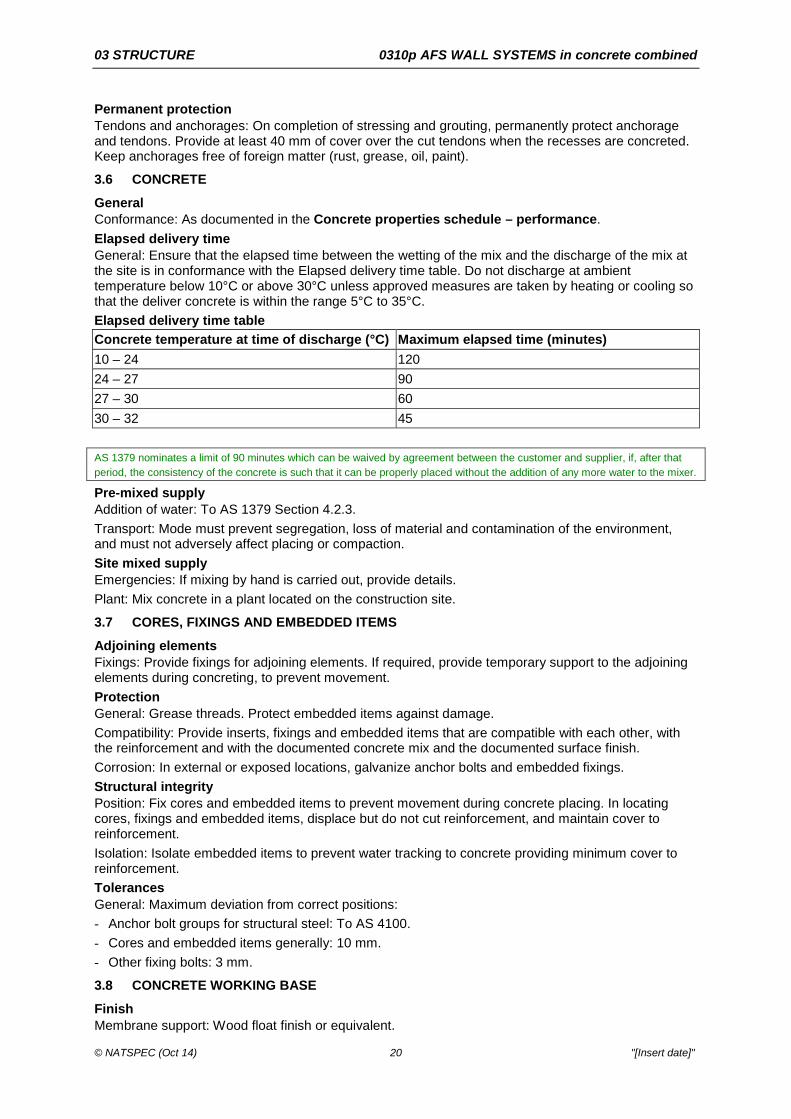
Permanent protection Tendons and anchorages: On completion of stressing and grouting, permanently protect anchorage and tendons. Provide at least 40 mm of cover over the cut tendons when the recesses are concreted. Keep anchorages free of foreign matter (rust, grease, oil, paint).
3.6 CONCRETE
General Conformance: As documented in the Concrete properties schedule – performance. Elapsed delivery time General: Ensure that the elapsed time between the wetting of the mix and the discharge of the mix at the site is in conformance with the Elapsed delivery time table. Do not discharge at ambient temperature below 10°C or above 30°C unless approved measures are taken by heating or cooling so that the deliver concrete is within the range 5°C to 35°C. Elapsed delivery time table Concrete temperature at time of discharge (°C) Maximum elapsed time (minutes) 10 – 24 120 24 – 27 90 27 – 30 60 30 – 32 45 AS 1379 nominates a limit of 90 minutes which can be waived by agreement between the customer and supplier, if, after that period, the consistency of the concrete is such that it can be properly placed without the addition of any more water to the mixer.
Pre-mixed supply Addition of water: To AS 1379 Section 4.2.3. Transport: Mode must prevent segregation, loss of material and contamination of the environment, and must not adversely affect placing or compaction. Site mixed supply Emergencies: If mixing by hand is carried out, provide details. Plant: Mix concrete in a plant located on the construction site.
3.7 CORES, FIXINGS AND EMBEDDED ITEMS
Adjoining elements Fixings: Provide fixings for adjoining elements. If required, provide temporary support to the adjoining elements during concreting, to prevent movement. Protection General: Grease threads. Protect embedded items against damage. Compatibility: Provide inserts, fixings and embedded items that are compatible with each other, with the reinforcement and with the documented concrete mix and the documented surface finish. Corrosion: In external or exposed locations, galvanize anchor bolts and embedded fixings. Structural integrity Position: Fix cores and embedded items to prevent movement during concrete placing. In locating cores, fixings and embedded items, displace but do not cut reinforcement, and maintain cover to reinforcement. Isolation: Isolate embedded items to prevent water tracking to concrete providing minimum cover to reinforcement. Tolerances General: Maximum deviation from correct positions: - Anchor bolt groups for structural steel: To AS 4100. - Cores and embedded items generally: 10 mm. - Other fixing bolts: 3 mm.
3.8 CONCRETE WORKING BASE
Finish Membrane support: Wood float finish or equivalent.

03 STRUCTURE 0310p AFS WALL SYSTEMS in concrete combined
© NATSPEC (Oct 14) 21 "[Insert date]"
Installation General: Lay over the base or subgrade and screed to the required level. Surface tolerance Deviation: Flatness tolerance Class B.
3.9 PLACING AND COMPACTION
Placing AFS LOGICWALL® specific requirements: - Pump via a 50 mm diameter delivery hose. - Walls up to 3 m in height: Fill in 2 passes and limit to 1.5 m high lift per pass. - Walls of 3 m to 4.2 m in height: Fill in 3 to 4 passes and limit first 2 passes to 1 m high. Standard AFS LOGICWALL® panels can be manufactured in any height from 200 mm up to 4.2 m. Heights exceeding 4.2 m can be manufactured upon request as a special order.
- Allow at least 1 hour between passes. AFS REDIWALL® specific requirements: - Pump via a 50 mm diameter delivery hose. - Walls up to 3 m in height: Fill in minimum 1 pass. - Walls of 3 m to 6.5 m in height: Fill in 2 to 3 passes and limit first 2 passes to 2.1 m high. - Allow at least 1 hour between passes. Other concrete works: - Horizontal transport: Use suitable conveyors, clean chutes, troughs or pipes for horizontal transport
of concrete. - Methods: Avoid segregation and loss of concrete, and minimise plastic settlement. Maintain a
generally vertical and plastic concrete edge during placement. - Horizontal elements: Place concrete in layers not more than 300 mm thick. Compact the following
layer into previous layer before previous layer has taken initial set. Compaction AFS LOGICWALL® specific requirements: - Vibrate with a 40 mm diameter needle vibrator, placing the vibrator in the upper 300 mm of the wall
panel and rattling the steel stud framework and reinforcement bars. For the last 300 mm lift of concrete, the vibrator can be placed directly into concrete. Over vibration or lowering the vibrator into the wall greater than 300 mm can cause concrete fluidisation and could result in bulges and blowouts of the panel.
AFS REDIWALL® specific requirements: - Use a 40 mm diameter needle vibrator as appropriate to remove entrapped air and to fully compact
the mix. Other concrete works: - Use immersion and screed vibrators accompanied by hand methods as appropriate to remove
entrapped air and to fully compact the mix. - Do not allow vibrators to come into contact with set concrete, reinforcement or items including pipes
and conduits embedded in concrete. Do not use vibrators to move concrete along the forms. Avoid over-vibration that may cause segregation.
Placing records Log book : Keep on site and make available for inspection a log book recording each placement of concrete, including the following: - Date. - Specified grade and source of concrete. - Slump measurements. - The portion of work. - Volume placed. Rain Protection : During placement and before setting, protect the surface from damage.

03 STRUCTURE 0310p AFS WALL SYSTEMS in concrete combined
© NATSPEC (Oct 14) 22 "[Insert date]"
AFS LOGICWALL®: Saturated panels should be left to dry, prior to placement of concrete. Time between adjacent placements General: As documented in the Minimum time delay schedule. Vertical elements Placement : Limit the free fall of concrete to maximum of 2000 mm. Placing in cold weather The CCAA Datasheet – CCAA Data Sheet Cold-Weather Concreting recommends taking precautions when the air temperature falls below 10°C.The effects on placing concrete in cold weather include:
• Extended setting times of concrete.
• Slower strength gain.
• Increased risk of cracking.
• Freezing of the concrete.
Actions to prevent damage from cold weather include protecting the concrete from cold winds and reduced temperature.
Cement: Do not use high alumina cement. Placing concrete: Maintain temperature of the freshly mixed concrete at 5°C or more. Formwork and reinforcement: Before and during placing maintain temperature at 5°C or more. Severe weather: If severe weather conditions are predicted, use high early strength cement. Temperature control: Heat the concrete materials, other than cement, to the minimum temperature necessary so that the temperature of the placed concrete is within the documented limits. Admixtures: Do not use calcium chloride, salts, chemicals or other material in the mix to lower the freezing point of the concrete. Frozen materials: Do not allow frozen materials or materials containing ice to enter the mixer, and keep free of frost and ice any formwork, materials, and equipment coming in contact with the concrete. Maximum temperature of water: 60°C when placed in mixer. Freezing : Prevent concrete from freezing. Placing in hot weather The CCAA Datasheet – CCAA Data Sheet Hot-weather concreting recommends taking precautions when the air temperature rises above 30°C and increases with high wind speeds or low humidity. The effects on placing concrete in hot weather include:
• Setting time reduced.
• Workability and slump reduced.
• Strength development altered.
• Poor surface and texture appearance.
• Plastic shrinkage cracking increased.
• Thermal cracking.
Actions to prevent damage from hot, dry and windy weather include:
• Keep temperature down, by wetting, shading and pouring in the cooler part of the day.
• Minimise delays.
• Control of loss of water through evaporation by the use of aliphatic alcohol.
• Protection of the concrete from wind and drying.
• Ensure proper curing.
Handling: Prevent premature stiffening of the fresh mix and reduce water absorption and evaporation losses. Mix, transport, place and compact the concrete in conformance with the Elapsed delivery time table. Placing concrete: Maintain the temperature of the freshly mixed concrete in conformance with the Hot weather placing table. Evaporation control barriers: Erect barriers to protect freshly placed concrete from drying winds. Formwork and reinforcement: Before and during placing, maintain temperature at 35°C or less. Temperature control: Select one or more of the following methods of maintaining the temperature of the placed concrete at 35°C or less: - Cool the concrete using liquid nitrogen injection before placing. - Cover the container in which the concrete is transported to the forms.

03 STRUCTURE 0310p AFS WALL SYSTEMS in concrete combined
© NATSPEC (Oct 14) 23 "[Insert date]"
- Spray the coarse aggregate using cold water before mixing. - Use chilled mixing water. Hot weather placing table Concrete element Temperature limit Normal concrete in footings, beams, columns, walls and slabs
35°C
Concrete in sections 1 m or more in all dimensions except for concrete of strength 40 MPa or more, in sections exceeding 600 mm in thickness
27°C
Placing under water General: Do not place under water unless conditions prevent dewatering. Minimum cement content for the mix: Increase by 25%.
3.10 CURING
General Requirements: Taking into account the average ambient temperature at site over the relevant period affecting the curing, adopt procedures to ensure the following: - Curing: Cure continuously from completion of finishing until the total cumulative number of days or
fractions of days, during which the air temperature in contact with the concrete is above 10°C, is at least the following, unless accelerated curing is adopted: . Fully enclosed internal surfaces/Early age concrete: 3 days. . Other concrete surfaces: 7 days.
- End of curing period: Prevent rapid drying out at the end of the curing period. - Protection: Maintain at a reasonably constant temperature with minimum moisture loss, during the
curing period. - Curing method: [complete/delete] To limit early age shrinkage: Consider using an aliphatic alcohol before the application of particular curing compound.
Curing compounds Application: Provide a uniform continuous flexible coating without visible breaks or pinholes, which remains unbroken at least for the required curing period after application. Substrates: Do not use wax-based or chlorinated rubber-based curing compounds on surfaces forming substrates to applied finishes, concrete toppings and cement-based render. Self levelling toppings: If used also as curing compounds, confirm compliance with AS 3799. Visually important surfaces: Apply curing compounds to produce uniform colour on adjacent surfaces. Cold weather curing Temperature: Maintain concrete surface temperatures above 5°C for the duration of the curing period. Hot weather curing Curing compounds: If it is proposed to use curing compounds, provide details. Protection: Select a protection method as applicable. - If the concrete temperature is more than 25°C or if not protected against drying winds, protect the
concrete using a fog spray application of aliphatic alcohol evaporation retardant. - If ambient shade temperature is more than 35°C, protect from wind and sun using an evaporative
retarder until curing is commenced. - Immediately after finishing, either cover exposed surfaces using an impervious membrane or
hessian kept wet until curing begins, or apply a curing compound. Water curing Method: If water is used, pond or continuously sprinkle in such a way as to not cause damage to the concrete surface, for the required curing period.

03 STRUCTURE 0310p AFS WALL SYSTEMS in concrete combined
© NATSPEC (Oct 14) 24 "[Insert date]"
3.11 JOINTS
Construction joints Location: Do not relocate or eliminate construction joints, or form undocumented construction joints. If emergency construction joints are made necessary by unforeseen interruptions to the concrete pour, submit a report on the action taken. Finish: Butt join the surfaces of adjoining pours. In visually important surfaces make the joint straight and true, and free from blemishes impermissible for its surface finish class. Preparation: Roughen and clean the hardened concrete joint surface. Remove loose or soft material, free water, foreign matter and laitance. Dampen the surface just before placing the fresh concrete and coat with a neat cement slurry. Expansion joints Joint filling: Fill with jointing materials as documented. Finish visible jointing material neatly flush with adjoining surfaces. Preparation: Before filling, dry and clean the joint surfaces, and prime. Watertightness: Apply the jointing material so that joints subject to ingress of water are made watertight. Jointing materials: Provide jointing materials compatible when used together, and non-staining to concrete in visible locations. Bond breaking: Provide back-up materials for sealants, including backing rods, which do not adhere to the sealant. They may be faced with a non-adhering material. Foamed materials (in compressible fillers): Closed-cell or impregnated, not water absorbing. Slip joints Requirement: If concrete slabs are supported on masonry, provide proprietary slip joints.
3.12 SURFACE MODIFIERS
General Application: Apply to clean surfaces to the manufacturer’s recommendations.
3.13 FORMED SURFACES
General Surface finish: Provide formed concrete finishes as documented in the Formed surface finishes schedule. Damage: Do not damage concrete works through premature removal of formwork. Curing General: If forms are stripped when concrete is at an age less than the minimum curing period, commence curing exposed faces as soon as the stripping is completed. Evaluation of formed surfaces General: If evaluation of formed surface tolerance or colour is required, complete the evaluation before surface treatment. Surface repairs Surface repair method: If surface repairs are required, submit proposals. Finishing methods Details : If soffits of concrete elements or faces of concrete columns are to have a finish other than an off-form finish, provide finishes as documented. Blasted finishes: - Abrasive: Blast the cured surface using hard, sharp graded abrasive particles until the coarse
aggregate is in uniform relief. - Light abrasive: Blast the cured surface using hard, sharp graded abrasive particles to provide a
uniform matt finish without exposing the coarse aggregate. - Type of abrasive particles: [complete/delete] e.g. Steel shot or fine aggregate.
Bush hammered finish: Remove the minimum matrix using bush hammering to expose the coarse aggregate, recessing the matrix no deeper than half the aggregate size, to give a uniform texture.

03 STRUCTURE 0310p AFS WALL SYSTEMS in concrete combined
© NATSPEC (Oct 14) 25 "[Insert date]"
Exposed aggregate finish: Remove the vertical face formwork while the concrete is green. Wet the surface and scrub with stiff fibre or wire brushes, flushing continuously with clean water, until the aggregate is uniformly exposed. Do not use acid etching. Rinse the surface with water. See CCAA Briefing 02 for information on exposed aggregate finishes.
Floated finishes: - Sand floated finish: Remove the vertical face forms while the concrete is green. Wet the surface and
rub using a wood float. Rub fine sand into the surface until a uniform colour and texture are produced.
- Grout floated finish: Remove the forms while the concrete is green. Dampen the surface and spread a slurry, using hessian pads or sponge rubber floats. Remove surplus slurry and work until a uniform colour and texture are produced.
Smooth rubbed finish: Remove the vertical face forms while the concrete is green. Wet the surface and rub using a carborundum or similar abrasive brick until a uniform colour and texture are produced. Only the more common finishing methods are listed. Add other project specific requirements (e.g. polished, coloured).
3.14 UNFORMED SURFACES
General Surface finish: As documented in the Unformed surface finishes schedule. Finished levels: Strike off, screed and level slab surfaces to finished levels and to the flatness tolerance class documented. Surface repairs Surface repair method: If surface repairs are required, submit proposals. Finishing methods – primary finish Machine float finish: - After levelling, consolidate the surface using a machine float. - Cut and fill and refloat immediately to a uniform, smooth, granular texture. - Hand float in locations inaccessible to the machine float. Steel trowel finish: After machine floating finish, as follows: - Use power or hand steel trowels to produce a smooth surface relatively free from defects. - When the surface has hardened sufficiently, re-trowel to produce the final consolidated finish free of
trowel marks and uniform in texture and appearance. Burnished finish: Continue steel trowelling until the concrete surface attains a polished or glossy finish, uniform in texture and appearance, and free of trowel marks and defects. For burnished concrete finishes see the following publications:
• CCAA Briefing 05.
• CCAA Data Sheet The specification of burnished concrete finish.
The Datasheet provide suggested specification clauses which may be considered for inclusion by the engineer in the appropriate concrete worksections.
Wood float finish: After machine floating, use wood or plastic hand floats to produce the final consolidated finish free of float marks and uniform in texture and appearance. Broom finish: After machine floating and steel trowelling use a broom or hessian belt drawn across the surface to produce a coarse even-textured transverse-scored surface. Scored or scratch finish: After screeding, use a stiff brush or rake drawn across the surface before final set, to produce a coarse scored texture. Sponge finish: After machine floating and steel trowelling, use a damp sponge to wipe the surface to produce an even textured sand finish. Exposed aggregate finish: After floating and when concrete has stiffened, wet the surface and scrub with stiff fibre or wire brushes, flushing continuously with clean water, until the aggregate is uniformly exposed. Rinse the surface with water. See CCAA Briefing 02 for information on exposed aggregate finishes.

03 STRUCTURE 0310p AFS WALL SYSTEMS in concrete combined
© NATSPEC (Oct 14) 26 "[Insert date]"
Finishing methods – supplementary finish Abrasive blast: After steel trowelling, abrasive blast the cured surface to provide texture or to form patterns without exposing the coarse aggregate, using hard, sharp graded abrasive particles. - Type of abrasive particles: [complete/delete] e.g. Steel shot or Fine aggregate.
Coloured applied finish: After machine floating, apply a proprietary liquid or dry shake material to the manufacturer’s recommendations and trowel to achieve the required appearance. Product: [complete/delete] Colour: [complete/delete] Stamped and coloured faux paved or cobblestone finish: Provide a proprietary finishing system. Product: [complete/delete] Colour: [complete/delete] Polished finish: After steel trowelling, grind the cured surface of the concrete. - Method: [complete/delete] - Colour: [complete/delete] - Patterns and textures: [complete/delete] - Sealing: [complete/delete] For polished or honed concrete finishes see the following publications:
• CCAA Briefing 05.
• CCAA Data Sheet The specification of honed or polished concrete finishes.
The Datasheet provide suggested specification clauses which may be considered for inclusion by the engineer in the appropriate concrete worksections. The range of treatments to achieve and to embellish polished concrete surfaces is large, and includes colouring, texturing, patterning by saw cutting or inlaying of metal or timber strips or of tiles or pavers. The effect required should be comprehensively documented by the architect.
For slip resistance a number of the unformed surface finishes listed satisfy the requirements, to differing degrees. Refer to CCAA Road Note 64, Section 011 for more information on suitability for residential streets and public footpaths.
3.15 TRAINING
General General: Training for the installation of AFS LOGICWALL® panels can be provided upon request from AFS. Call AFS Systems Pty Ltd® for further information.
3.16 COMPLETION
Formwork removal Extent: Remove formwork, other than profiled steel reinforcement decking, including formwork in concealed locations, but excepting lost formwork. Timing: Do not disturb forms until concrete is hardened enough to withstand formwork movements and removal without damage. Stripping: - General: To AS 3600 where it is more stringent than AS 3610.1. - Vertical formwork: To AS 3610.1 Appendix B Table B1. - Multi-storey work: Remove formwork without disturbing props supporting succeeding floors. - Post-tensioned concrete: Remove formwork supporting post-tensioned concrete members to
AS 3600 clause 17.6.2.7. AFS brace removal General: Do not remove bracing within 24 hours of pouring slab above or until roof has been attached. If early brace removal is desired, submit proposals to structural engineer for approval. Protection General: Protect the concrete from damage due to construction loads, physical and thermal shocks, and excessive vibrations, particularly during the curing period. Surface protection: Protect finished concrete surfaces and applied finishes from damage.

03 STRUCTURE 0310p AFS WALL SYSTEMS in concrete combined
© NATSPEC (Oct 14) 27 "[Insert date]"
4 SELECTIONS
Schedules are a way of documenting a selection of proprietary or generic products or systems by their properties. Provide their locations here and/or on the drawings. When showing items in both places, identify them with a common code or tag to assist coordination. Schedules are well suited to multiple variants of the same item. If there is only a single instance of different items, a simple list may be sufficient. Make sure there is an entry for every item documented.
Duplicate and customise these Schedules, adding and deleting rows and columns, as required, e.g. delete rows if the selection is by the contractor or a proprietary product is selected. A proprietary product is usually selected on the basis of the properties it embodies, so there is generally no need to spell them out in a schedule – an exception being where they relate to options to, or variations from, a standard product.
4.1 SELECTIONS
Aggregate property schedule Aggregate property Tests Limits Particle density
Water absorption
Particle size
Durability Tendon schedule Structural element Tendon material Tendon size (mm)
It is preferable for the tendon material and size to be shown on the drawings. Only if it is not, it may be scheduled here (do not duplicate). If it is delete this clause/schedule.
Tendon material: Specify the type and grade of strand, wire or bar. See AS/NZS 4672.1 and AS/NZS 4672.2.
Tendon size: State the number and nominal diameter of strands, wires or bars in each tendon.
Formwork dimensional deviation schedule Dimension or measurement Location or element Deviation (mm)
Formed surface finishes schedule Property A B C Location
Surface finish class to AS 3610.1
Form lining type
Colour control
Bolt hole filling
Surface finish type
Evaluation A, B, C: These designate each instance or type of the item scheduled. Edit to align with the project’s codes or tags.
Coordinate codes in the Schedule with those that appear on drawings.

03 STRUCTURE 0310p AFS WALL SYSTEMS in concrete combined
© NATSPEC (Oct 14) 28 "[Insert date]"
Surface finish to AS 3610.1 : For applicability of surface classes, see AS 3610.1 Table 3.2.1.
Evaluation: Required. For evaluation of surface tolerance or colour. Delete if not required.
Surface finish Class 1 formwork Colour control: [complete/delete] Critical faces of elements: [complete/delete] Distance between face steps (mm): [complete/delete] Form face span and direction of span: [complete/delete] Repairs: Not permitted. Surface pattern details and accuracy: [complete/delete] Surface treatment pattern of part of surface: [complete/delete] Tie rod pattern: [complete/delete] Surface finish Class 2 formwork Add Class 3 formwork if appropriate.
Colour control: [complete/delete] Critical faces of elements: [complete/delete] Distance between face steps (mm): [complete/delete] Form face span and direction of span (Class 2 only): [complete/delete] Liner details, pattern and accuracy: [complete/delete] Surface pattern details and accuracy: [complete/delete] Surface treatment of whole: [complete/delete] Surface treatment pattern of part of surface: [complete/delete] Tie rod pattern: [complete/delete] Concrete properties schedule – performance Property A B C Normal and special class
Air entrainment – air volume (%)
Maximum aggregate size (mm)
Assessment process
Slump (mm)
Strength grade/characteristic compressive strength f’c (MPa)
Special class
Bleeding (mL/mm²)
Cement type
Density of hardened concrete (kg/m3)
Density of plastic concrete (kg/m3)
Drying shrinkage
Duration of air drying
Early age strength (MPa)
Flexural strength (MPa)
Indirect tensile strength (MPa)
Mineral oxide content
Mix type
Water:cement ratio maximum

03 STRUCTURE 0310p AFS WALL SYSTEMS in concrete combined
© NATSPEC (Oct 14) 29 "[Insert date]"
Property A B C 56 day shrinkage strain tested to AS 1012.13 A, B, C: These designate each instance or type of the item scheduled. Edit to align with the project’s codes or tags.
Coordinate codes in the Schedule with those that appear on drawings.
Concrete for AFS LOGICWALL®
The concrete infill is a proprietary mix designed with enhanced flow characteristics. The mix is designed such that segregation and blowouts are minimised whilst achieving the required level of compaction. Basic characteristics are:
• F’c = 25-50 MPa as required by the structural design.
• 7-10 mm maximum aggregate.
• Batched at 80 mm slump before addition of admixtures.
• Admixtures include plasticiser and fly ash added to increase slump to 140-160 mm. Request slump test on site.
Concrete for AFS REDIWALL®
The concrete infill is a proprietary mix designed with enhanced flow characteristics. The mix is designed such that the required level of compaction is achieved. Basic characteristics are:
• F’c = Min 25 MPa as required by the structural design.
• Maximum 10 mm rounded aggregate.
• Minimum 100-125 mm slump at the point of discharge.
• Maximum water:cement ratio: 0.55
• The use of fly ash is not recommended.
General
A, B, C: These designate each instance or type of the item scheduled. Edit to align with the project’s codes or tags.
Coordinate codes in the Schedule with those that appear on drawings.
Drying shrinkage: Generally between 500 to 800 με and not more than 1000 με For example, drying shrinkage at 56 days for the following are:
• a water tight structure is normally between 500 to 550 με.
• for concrete up to and including strength grade 32 is 650 µε and for higher strength grades is 700 µε.
Specifying unrealistically low standard drying shrinkage could potentially be difficult to achieve with locally available aggregates and can adversely affect the workability of the concrete, both factors could increase costs.
See CCAA Fact Sheet - Specifying low drying shrinkage ≠ crack control.
If the concrete is special class only because of the specification of a drying shrinkage less than 1000 µε, delete the special class section of the table and simply specify required drying shrinkage.
Duration of air drying: Standard drying period is 56 days.
Control tests schedule Concrete element
28 day strength
Transfer strength (MPa)
Days after pouring
Early strength (MPa)
Days after pouring
Minimum time delay schedule Between (pour locations) Minimum period between adjacent pours
(days) Adjacent pours abutting horizontal construction joints in walls or columns
Adjacent pours abutting vertical construction joints in walls
Columns and slabs
Floor slab construction joints

03 STRUCTURE 0310p AFS WALL SYSTEMS in concrete combined
© NATSPEC (Oct 14) 30 "[Insert date]"
Between (pour locations) Minimum period between adjacent pours (days)
Pour strips and adjacent concrete
Retaining wall construction joints Unformed surface finishes schedule Property A B C
Location
Flatness tolerance class
Primary finish
Supplementary finish
Slip resistance treatment
Slip resistance classification
Slip resistance site test of completed installation
Surface modifier
A, B, C: These designate each instance or type of the item scheduled. Edit to align with the project’s codes or tags.
Coordinate codes in the Schedule with those that appear on drawings.
Flatness tolerance: e.g. Class A, B or C.
Primary finish: e.g. Wood float.
Suggested primary finish and tolerance class for typical applied finishes:
• Resilient finishes: Steel trowelled finish, tolerance Class A.
• Carpet: Machine float finish, tolerance Class B.
• Floor tiles: Scored finish, tolerance Class C.
• Unfinished (plantrooms): Machine float, tolerance Class B.
• Substrates for bitumen membranes: Wood float or light broom finish, tolerance Class B.
Flatness tolerance: e.g. Class A, B or C.
Primary finish: e.g. wood float.
Supplementary finish: e.g. burnished.
Slip resistance classification: For selections refer to SAA HB 197 and SAA HB 198, NATSPEC TECHnote DES 001 and CCAA Data Sheet Slip resistance of residential concrete paving surfaces - Slip Resistance of Residential Concrete Paving Surfaces. Select from:
• Wet pendulum: Select V, W, X, Y or Z.
• Dry floor friction: Select Class F (≥ 0.4).
Slip resistance site test of completed installation: e.g. Required. Delete if not required.
Refer to NATSPEC TECHnote DES 001 on slip resistance performance.
This schedule lists typical properties of products and/or processes which may need to be documented by defining values for the properties. Values can be words or numbers with units. Provide a column for each type of unformed surface finish, which can then be referenced on schedules and drawings. Use the specification to define one or more types and use drawings and schedules to define locations and values.
This single table may be divided into multiple tables if you prefer. It may be used merely as a checklist in which case make sure the properties are adequately defined in other documents. Add or delete rows and columns and edit their names as required.
REFERENCED DOCUMENTS The following documents are incorporated into this worksection by reference: AS 1012 Methods of testing concrete AS 1012.1 2014 Sampling of fresh concrete AS 1012.8.1 2014 Method for making and curing concrete - Compression and indirect tensile test
specimens AS 1012.8.2 2014 Method for making and curing concrete - Flexure test specimens AS 1012.9 2014 Compressive strength tests - Concrete, mortar and grout specimens

03 STRUCTURE 0310p AFS WALL SYSTEMS in concrete combined
© NATSPEC (Oct 14) 31 "[Insert date]"
AS 1012.13 1992 Determination of the drying shrinkage of concrete for samples prepared in the field or in the laboratory
AS/NZS 1314 2003 Prestressing anchorages AS 1349 1986 Bourdon tube pressure and vacuum gauges AS 1379 2007 Specification and supply of concrete AS 1397 2011 Continuous hot-dip metallic coated steel sheet and strip - Coatings of zinc and zinc
alloyed with aluminium and magnesium AS 1478 Chemical admixtures for concrete, mortar and grout AS 1478.1 2000 Admixtures for concrete AS 2327 Composite structures AS 2327.1 2003 Simply supported beams AS 2758 Aggregates and rock for engineering purposes AS 2758.1 1998 Concrete aggregates AS 2870 2011 Residential slabs and footings AS/NZS 2908 Cellulose-cement products AS/NZS 2908.2 2000 Flat sheet AS 3582 Supplementary cementitious materials for use with portland and blended cement AS 3582.1 1998 Fly ash AS 3600 2009 Concrete structures AS 3610 1995 Formwork for concrete AS 3610.1 2010 Documentation and surface finish AS 3735 2001 Concrete structures retaining liquids AS 3799 1998 Liquid membrane-forming curing compounds for concrete AS 3972 2010 General purpose and blended cements AS 4100 1998 Steel structures AS 4586 2013 Slip resistance classification of new pedestrian surface materials AS 4663 2013 Slip resistance measurement of existing pedestrian surfaces AS/NZS 4671 2001 Steel reinforcing materials AS/NZS 4672 Steel prestressing materials AS/NZS 4672.1 2007 General requirements AS/NZS 4672.2 2007 Testing requirements AS/NZS 4680 2006 Hot-dip galvanized (zinc) coatings on fabricated ferrous articles AS 6669 2007 Plywood - Formwork CIA CPN35 2003 Fibres in concrete Designer Manual 2012 AFS LOGICWALL® Designer Manual Technical Guide 2014 AFS REDIWALL® Technical Guide The following documents are mentioned only in the Guidance text: AS/NZS 2312 2002 Guide to the protection of structural steel against atmospheric corrosion by the use of
protective coatings AS/NZS 2589 2007 Gypsum linings - Application and finishing AS 3735 2001 Concrete structures retaining liquids AS 3735 Supp 1 2001 Concrete structures retaining liquids - Commentary (Supplement to AS 3735-2001) ARC Handbook 2010 Reinforcement handbook - Your guide to steel reinforcement SAA HB 28 1997 Design of residential slabs and footings SAA HB 64 2002 Guide to concrete construction SAA HB 67 1995 Concrete practice on building sites SAA HB 71 2011 Reinforced concrete design in accordance with AS 3600-2009 SAA HB 84 2006 Guide to concrete repair and protection SAA HB 155 2002 Guide to the use of recycled concrete and masonry materials SAA HB 197 1999 An introductory guide to the slip resistance of pedestrian surface materials AIA EDG 71 RC 2012 Life cycle energy analysis AIA EDG DES 4 1995 Thermal mass in building design AIA EDG PRO 2 2006 Embodied energy of building materials BCA 3.2.4 2014 Acceptable construction - Site classification BCA C1.10 2014 Fire resistance - Fire resistance and stability - Fire hazard properties CCAA Data Sheet BCF 2010 The specification of burnished concrete finish CCAA Data Sheet CWC 2004 Cold-Weather Concreting CCAA Data Sheet HPC 2010 The specification of honed or polished concrete finishes CCAA Data Sheet HWC 2004 Hot-Weather Concreting CCAA Data Sheet TCS 2005 Tolerances for Concrete Surfaces CCAA Datasheet SRR 2003 Slip resistance of residential concrete paving surfaces CCAA Fact Sheet 2010 Specifying low drying shrinkage crack control CCAA Briefing 02 2007 Exposed-aggregate finishes for flatwork CCAA Briefing 05 2006 Polished concrete floors CCAA Briefing 11 2010 Sustainable concrete materials CCAA Briefing 12 2010 Thermal mass benefits for housing CCAA Briefing 13 2010 Sustainable concrete buildings CCAA Briefing 18 2011 Houses for flood-prone areas CCAA T49 2003 Guide to residential floors CCAA T56 2005 Guide to residential slabs and footings in saline environments CCAA T58 2007 Climate-responsive house design with concrete CCAA Road Note 64 2003 Beyond the pavement CIA CPN17 2008 The use of galvanized reinforcement in concrete CIA CPN28 2005 Watertight concrete structures CIA Z13 2001 Performance criteria for concrete in marine environments

03 STRUCTURE 0310p AFS WALL SYSTEMS in concrete combined
© NATSPEC (Oct 14) 32 "[Insert date]"
CIA Z16 2011 Geopolymer concrete - recommended practice CIA Z40 2005 Super-workable Concrete NATSPEC DES 001 2005 Slip resistance performance NATSPEC DES 006 2007 Specifying concrete NATSPEC DES 010 2009 Atmospheric corrosivity categories for ferrous products NATSPEC DES 020 2011 Fire behaviour of building materials and assemblies NATSPEC GEN 006 2007 Product specifying and substitution NATSPEC TR 01 2013 Specifying ESD NP PCH 2009 Precast concrete handbook SAA HB 198 2014 Guide to the specification and testing of slip resistance of pedestrian surfaces