03 Transmission Process
31
GSM Transmission Process STAGE 1: ANALOG TO DIGITAL (A/D) CONVERSION STAGE 2: SEGMENTATION STAGE 3: SPEECH CODING STAGE 4: CHANNEL CODING STAGE 5: INTERLEAVING STAGE 6: CIPHERING/ENCRYPTION STAGE 7: BURST FORMATTING STAGE 8: MODULATION & TRANSMISSION
Transcript of 03 Transmission Process
8/12/2019 03 Transmission Process
http://slidepdf.com/reader/full/03-transmission-process 1/31
GSM Transmission Process
STAGE 1: ANALOG TO DIGITAL (A/D)CONVERSION
STAGE 2: SEGMENTATION
STAGE 3: SPEECH CODING STAGE 4: CHANNEL CODING
STAGE 5: INTERLEAVING
STAGE 6: CIPHERING/ENCRYPTION STAGE 7: BURST FORMATTING
STAGE 8: MODULATION & TRANSMISSION

8/12/2019 03 Transmission Process
http://slidepdf.com/reader/full/03-transmission-process 2/31
Stage 1: Analog To Digital (A/D) Conversion
MS actually converts the analog speech informationinto digital form for transmission using a digital
signal.
The analog to digital (A/D) conversion process
outputs a collection of bits: binary ones and zeroswhich represent the speech input.

8/12/2019 03 Transmission Process
http://slidepdf.com/reader/full/03-transmission-process 3/31
Stage 1: Analog To Digital (A/D) Conversion
The A/D conversion is performed by using aprocess called Pulse Code Modulation
(PCM).
PCM involves three main steps: Sampling
Quantization
Coding

8/12/2019 03 Transmission Process
http://slidepdf.com/reader/full/03-transmission-process 4/31
Stage 1: Analog To Digital (A/D) Conversion
Sampling Sampling involves measuring the analog signal at
specific time intervals.
The accuracy of describing the analog signal in digital
terms depends on how often the analog signal is
sampled.
This is expressed as the sampling frequency.
8/12/2019 03 Transmission Process
http://slidepdf.com/reader/full/03-transmission-process 5/31
Stage 1: Analog To Digital (A/D) Conversion
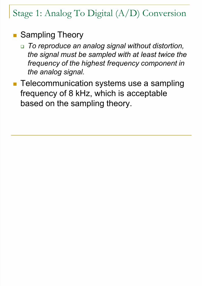
Sampling Theory To reproduce an analog signal without distortion,
the signal must be sampled with at least twice the
frequency of the highest frequency component in
the analog signal.
Telecommunication systems use a sampling
frequency of 8 kHz, which is acceptable
based on the sampling theory.
8/12/2019 03 Transmission Process
http://slidepdf.com/reader/full/03-transmission-process 6/31
Stage 1: Analog To Digital (A/D) Conversion
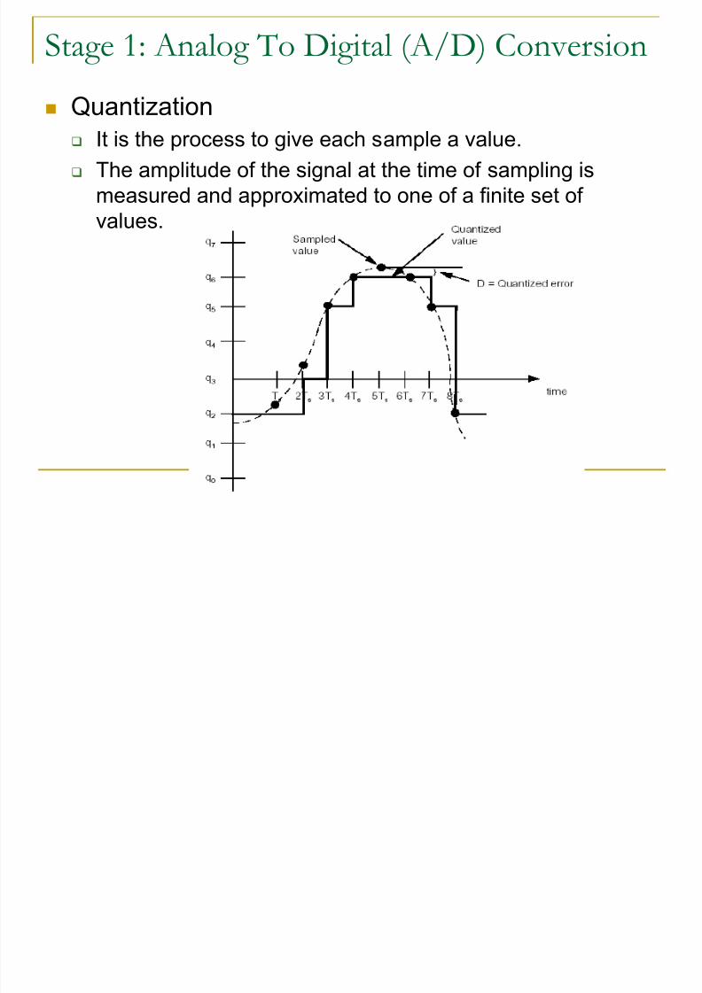
Quantization
It is the process to give each sample a value.
The amplitude of the signal at the time of sampling is
measured and approximated to one of a finite set of
values.

8/12/2019 03 Transmission Process
http://slidepdf.com/reader/full/03-transmission-process 7/31
Stage 1: Analog To Digital (A/D) Conversion
Quantization error is the actual difference betweensample value and quantized value.
The degree of accuracy depends on the
number of quantization levels used.
Within common telephony, 256 levels are
used while in GSM, 8192 levels are used.

8/12/2019 03 Transmission Process
http://slidepdf.com/reader/full/03-transmission-process 8/31
Stage 1: Analog To Digital (A/D) Conversion
Coding Coding involves converting the quantized values into
binary.
Every value is represented by a binary code of 13 bits
(213 = 8192). For example, a quantized value of 2,157
would have a bit pattern of 0100001101101:
Figure: Coding of quantized value 2157

8/12/2019 03 Transmission Process
http://slidepdf.com/reader/full/03-transmission-process 9/31
Stage 1: Analog To Digital (A/D) Conversion
Summary The result from the process of A/D conversion is
8,000 samples per second of 13 bits each. This isa bit rate of 104 kbits/s.
When it is considered that 8 subscribers use oneradio channel, the overall bit rate would be 8 x10⁴ kbits/s = 832 kbits/s.
Recalling the general rule of 1 bit per Hertz, thisbit rate would not fit into the 200 kHz available forall 8 subscribers.
The bit rate must be reduced somehow - this isachieved using segmentation and speech coding.

8/12/2019 03 Transmission Process
http://slidepdf.com/reader/full/03-transmission-process 10/31
Stage 2: Segmentation Stage 3: Speech Coding
The key to reducing the bit rate is to sendinformation about the speech instead of the speech
itself.
Explanation

8/12/2019 03 Transmission Process
http://slidepdf.com/reader/full/03-transmission-process 11/31
Stage 2: Segmentation Stage 3: Speech Coding
In GSM, the speech coding process analyzesspeech samples and outputs parameters of
what the speech consists of the tone, length
of tone, pitch, etc.
This is then transmitted through the network
to another MS, which generates the speech
based on these parameters.

8/12/2019 03 Transmission Process
http://slidepdf.com/reader/full/03-transmission-process 12/31
Stage 2: Segmentation Stage 3: Speech Coding
Process of segmentation and speech coding
The human speech process starts in the vocal
chords or speech organs, where a tone is
generated. The mouth, tongue, teeth, etc. act as a filter,
changing the nature of this tone.
The aim of speech coding in GSM is to send only
information about the original tone itself and aboutthe filter.

8/12/2019 03 Transmission Process
http://slidepdf.com/reader/full/03-transmission-process 13/31
Stage 2: Segmentation Stage 3: Speech Coding
Segmentation Given that the speech organs are relatively slow in
adapting to changes, the filter parameters representing the
speech organs are approximately constant during 20 ms.
For this reason, when coding speech in GSM, a block of 20
ms is coded into one set of bits.
In effect, it is similar to sampling speech at a rate of 50
times per second instead of the 8,000 used by A/D
conversion.

8/12/2019 03 Transmission Process
http://slidepdf.com/reader/full/03-transmission-process 14/31
Stage 2: Segmentation Stage 3: Speech Coding
Coding Instead of using 13 bits per sample as in A/D
conversion, GSM speech coding uses 260 bits.
This calculates as 50 x 260 = 13 kbits/s. This
provides a speech quality which is acceptable formobile telephony and comparable with wireline
PSTN phones.
8/12/2019 03 Transmission Process
http://slidepdf.com/reader/full/03-transmission-process 15/31
Stage 2: Segmentation Stage 3: Speech Coding
Types of speech coders
Some offer better speech quality, at the expense
of a higher bit rate (waveformcoders) .
Others use lower bit rates, at the expense of lowerspeech quality (vocoders).
The hybrid coder which GSM uses provides good
speech quality with a relatively low bit rate, at the
expense of speech coder complexity.

8/12/2019 03 Transmission Process
http://slidepdf.com/reader/full/03-transmission-process 16/31
Stage 2: Segmentation Stage 3: Speech Coding
Figure: Speech Quality Vs. Bit rate

8/12/2019 03 Transmission Process
http://slidepdf.com/reader/full/03-transmission-process 17/31
Stage 2: Segmentation Stage 3: Speech Coding
Summary
The GSM speech coder produces a bit rate of 13 kbits/sper subscriber.
When it is considered that 8 subscribers use one radiochannel, the overall bit rate would be 8 x 13 kbits/s = 104
kbits/s. This compares favorably with the 832 kbits/s from A/D
conversion.
However, speech coding does not consider the problems
which may be encountered on the radio transmission path. The next stages in the transmission process, channel
coding and interleaving, help to overcome these problems.

8/12/2019 03 Transmission Process
http://slidepdf.com/reader/full/03-transmission-process 18/31
Stage 4: Channel Coding
Channel coding in GSM uses the 260 bitsfrom speech coding as input to channel
coding and outputs 456 encoded bits.
The 260 bits are split according to their
relative importance:
Block 1: 50 very important bits
Block 2: 132 important bits and
Block 3: 78 not so important bits

8/12/2019 03 Transmission Process
http://slidepdf.com/reader/full/03-transmission-process 19/31
Stage 4: Channel Coding

8/12/2019 03 Transmission Process
http://slidepdf.com/reader/full/03-transmission-process 20/31
Stage 4: Channel Coding
The first block of 50 bits is sent through a blockcoder, which adds three parity bits that will result in
53 bits.
These three bits are used to detect errors in a
received message. The 53 bits from first block, the 132 bits from the
second block and 4 tail bits (total = 189) are sent to
a 1:2 convolutional coder which outputs 378 bits.
Bits added by the convolutional coder enable thecorrection of errors when the message is received.

8/12/2019 03 Transmission Process
http://slidepdf.com/reader/full/03-transmission-process 21/31
Stage 5: Interleaving
First Level of interleaving The channel coder provides 456 bits for every 20 ms of
speech.
These are interleaved, forming eight blocks of 57 bits
each.

8/12/2019 03 Transmission Process
http://slidepdf.com/reader/full/03-transmission-process 22/31
Stage 5: Interleaving What is a Burst?
The information format during one timeslot on the TDMA channel;that is, with regular time intervals (every time slot on a TDMA
channel, the user transmits or receives his information), we send
a burst of information (either speech or data).
A burst is considered as a period of RF carrier that is modulated
by a data stream.
A burst, therefore represents the physical content of a time slot
Normal Burst In a normal burst there is space for two of these speech blocks of
57 bits (Figure). Thus, if one burst transmission is lost, there is a 25% BER for the
entire 20 ms of speech (2/8 = 25%).

8/12/2019 03 Transmission Process
http://slidepdf.com/reader/full/03-transmission-process 23/31
Stage 5: Interleaving
Second Level of interleaving If only one level of interleaving is used, a loss of
this burst results in a total loss of 25%.
This is too much for the channel decoder to
correct.
A second level of interleaving can be introduced
to further reduce the possible BER to 12.5%.
Figure: Speech frame

8/12/2019 03 Transmission Process
http://slidepdf.com/reader/full/03-transmission-process 24/31
Stage 5: Interleaving
Second level of interleaving Instead of sending two blocks of 57 bits from the same 20
ms of speech within one burst, a block from one 20 ms and
a block from next sample of 20 ms are sent together.
A delay is introduced in the system when the MS must waitfor the next 20 ms of speech.
However, the system can now afford to loose a whole
burst, out of eight, as the loss is only 12.5% of the total bits
from each 20ms speech frame.
12.5% is the maximum loss level that channel decoder can
correct.

8/12/2019 03 Transmission Process
http://slidepdf.com/reader/full/03-transmission-process 25/31
Figure:Second Level of Interleaving

8/12/2019 03 Transmission Process
http://slidepdf.com/reader/full/03-transmission-process 26/31
Stage 6: Ciphering/Encryption
The purpose of ciphering is to encode the
burst so that it cannot be interpreted by any
other device than the intended receiver.
The ciphering algorithm in GSM is called the A5 algorithm.
It does not add bits to the burst, meaning that
the input and output to the ciphering processis the same as the input: 456 bits per 20 ms.

8/12/2019 03 Transmission Process
http://slidepdf.com/reader/full/03-transmission-process 27/31
Stage 7: Burst Formatting
Every transmission from an MS/BTS must includesome extra information such as the trainingsequence.
The process of burst formatting is to add these bits(along with some others such as tail bits) to the
basic speech/data being sent. This increases the overall bit-rate, but is necessary
to counteract problems encountered on the radiopath.
In GSM, the input to burst formatting is the 456 bitsreceived from ciphering.
Burst formatting adds a total of 136 bits per block of20 ms, bringing the overall total to 592 .
8/12/2019 03 Transmission Process
http://slidepdf.com/reader/full/03-transmission-process 28/31
Stage 7: Burst Formatting
However, each time slot on a TDMA frame is 576.92 µslong.
This provides enough time for 156.25 bits to be transmitted(each bit takes 3.692288 µs), but a burst only contains 148bits.
The rest of the space, 8.25 bit times, is empty and is calledthe Guard Period (GP).
This time is used to enable the MS/BTS “ramp up” and“ramp down”. To ramp up means to get power from thebattery/power supply for transmission.
Ramping down is performed after each transmission toensure that the MS is not transmitting during time slotsallocated to other MSs.

8/12/2019 03 Transmission Process
http://slidepdf.com/reader/full/03-transmission-process 29/31
Stage 7: Burst Formatting
The output of burst formatting is a burst of
156.25 bits or 625 bits per 20 ms.
When it is considered that there are 8
subscriber per TDMA frame, the overall bitrate for GSM can be calculated to be 270.83
kbits/s.

8/12/2019 03 Transmission Process
http://slidepdf.com/reader/full/03-transmission-process 30/31
Stage 8: Modulation & Transmission
The bits must then be sent over the air usinga carrier frequency.
GSM uses the GMSK modulation technique.
The bits are modulated onto a carrierfrequency and transmitted (e.g. 912.2 MHz).

8/12/2019 03 Transmission Process
http://slidepdf.com/reader/full/03-transmission-process 31/31
Assignment