
02/2016 Technical Manual MDT Presence Detector€¦ · Technical Manual Presence Detector...
44
MDT technologies GmbH,Geschäftsbereich Gebäudeautomation Tel.: +49-2263-880•Fax: +49-2263-4588•E-Mail:[email protected]•www.mdtautomation.de 1 02/2016 Technical Manual MDT Presence Detector SCN-P360D3.01 SCN-P360K3.01 SCN-GP360D3.01 SCN-G360K3.01 SCN-P360D4.01 SCN-P360K4.01
Transcript of 02/2016 Technical Manual MDT Presence Detector€¦ · Technical Manual Presence Detector...

MDT technologies GmbH,Geschäftsbereich Gebäudeautomation
Tel.: +49-2263-880•Fax: +49-2263-4588•E-Mail:[email protected]•www.mdtautomation.de 1
02/2016
Technical Manual
MDT Presence Detector
SCN-P360D3.01
SCN-P360K3.01
SCN-GP360D3.01
SCN-G360K3.01
SCN-P360D4.01
SCN-P360K4.01

Technical Manual Presence Detector SCN-P/G360XX.01
MDT technologies GmbH • 51766 Engelskirchen • Papiermühle 1
Tel.: +49-2263-880 • Fax: +49-2263-4588 • [email protected] • www.mdt.de 2
1 Content
1 Content ................................................................................................................................................. 2
2 Overview ............................................................................................................................................... 4
2.1 Overview Devices .......................................................................................................................... 4
2.2 Usage & Areas of use ..................................................................................................................... 4
2.3 Exemplary circuit diagram ............................................................................................................. 5
2.4 Installation & instructions for mounting ....................................................................................... 5
2.5 Functions ....................................................................................................................................... 8
2.5.1 Overview Functions ................................................................................................................ 9
2.6. Settings at the ETS-Software ...................................................................................................... 10
2.7. Starting up .................................................................................................................................. 10
3 Communication objects ...................................................................................................................... 11
3.1 Overview ...................................................................................................................................... 11
3.2 Default-settings oft he communication objects .......................................................................... 11
4 Reference ETS-Parameter .................................................................................................................. 13
4.1 General ........................................................................................................................................ 13
4.2 Light/ HCV .................................................................................................................................... 15
4.2.1 Sensor configuration ................................................................................................................ 15
4.2.2 Detector configuration ............................................................................................................. 17
4.2.3 Communication object settings ............................................................................................ 20
4.3 Brightness ........................................................................................................................................ 23
4.4 Calibration brightness value ............................................................................................................ 25
4.4.1 Approach at Teach-In with constant level light .................................................................... 27
4.4.2 Approach at Teach-In without constant level light .............................................................. 28
4.5 Constant level light .......................................................................................................................... 29
4.5.1 General settings/ Main principle regulation ........................................................................ 29
4.5.2 Available settings .................................................................................................................. 33
4.5.3 Scenes ................................................................................................................................... 37
4.5.4 Approach at Start-Up ............................................................................................................ 37
4.6 Master/Slave ................................................................................................................................... 38
4.6.1 Light groups .......................................................................................................................... 38
4.6.2 HVC ....................................................................................................................................... 38
4.7 Other/ Examples of use ............................................................................................................... 39
4.7.1 Blackboard light via second light group ............................................................................... 39

Technical Manual Presence Detector SCN-P/G360XX.01
MDT technologies GmbH • 51766 Engelskirchen • Papiermühle 1
Tel.: +49-2263-880 • Fax: +49-2263-4588 • [email protected] • www.mdt.de 3
5 Index ................................................................................................................................................... 40
5.1 List of illustrations ....................................................................................................................... 40
5.2 List of tables................................................................................................................................. 41
6 Attachment ......................................................................................................................................... 42
6.1 Statutory requirements ............................................................................................................... 42
6.2 Routine disposal .......................................................................................................................... 42
6.3 Assemblage .................................................................................................................................. 42
6.4 Datasheet .................................................................................................................................... 43

Technical Manual Presence Detector SCN-P/G360XX.01
MDT technologies GmbH • 51766 Engelskirchen • Papiermühle 1
Tel.: +49-2263-880 • Fax: +49-2263-4588 • [email protected] • www.mdt.de 4
2 Overview
2.1 Overview Devices
The Manual refers tot he following devices (Order ID respectively printed in bold letters):
SCN-P360D4.01 Presence Detector, 4 Pyro Detectors
o 4 Pyro-Detectors, individually programmable detection sensitivity for standby state
day, night and presence, switching options for movement and lightness, separate
communication object for night, Master/Slave function, Standby-/Orientation light, 2
area mode
SCN-P360K4.01 Presence Detector, 4 Pyro Detectors, constant level light control
o 4 Pyro-Detectors, individually programmable detection sensitivity for standby state
day, night and presence, switching options for movement and lightness, separate
communication object for night, Master/Slave function, Standby-/Orientation light, 2
area mode, extended constant level light control with proportional Master/Slave
function for up to 3 light groups
SCN-P360D3.01/ SCN-G360D3.01 Presence Detector, 3 Pyro Detectors
o 3 Pyro-Detectors, individually programmable detection sensitivity for standby state
day, night and presence, switching options for movement and lightness, separate
communication object for night, Master/Slave function, Standby-/Orientation light, 2
area mode
SCN-P360K3.01/ SCN-G360K3.01 Presence Detector, 3 Pyro Detectors, constant level light
control
o 3 Pyro-Detectors, individually programmable detection sensitivity for standby state
day, night and presence, switching options for movement and lightness, separate
communication object for night, Master/Slave function, Standby-/Orientation light, 2
area mode, constant level light control
2.2 Usage & Areas of use
The MDT Presence Detector switches the light accordingly to the brightness and presence. It can be
used for switching on demand to switch the light economically. Especially in public buildings, but also
in rarely used rooms as bath and WC, the presence detector can be used to minimalize the non-
essential switching periods. An additional channel transmits informations about presence in the
room to other subsections as Heating-control, air-conditioning, ventilation or shutter controlling. So
the presence detector can also be employed in a subsection comprehensive use. The presence
detectors SCN-P360K3.01 und SCN-P360K4.01 contains of an additional intelligent constant level light
control. The constant level light control can control up to 3 light bands in a way to hold the lightness
in a room continuously at a constant value.

Technical Manual Presence Detector SCN-P/G360XX.01
MDT technologies GmbH • 51766 Engelskirchen • Papiermühle 1
Tel.: +49-2263-880 • Fax: +49-2263-4588 • [email protected] • www.mdt.de 5
2.3 Exemplary circuit diagram
Figure 1: Exemplary circuit diagram
2.4 Installation & instructions for mounting
The following figure shows the adjustment of the particular sensors, identified with S1=sensor 1 to S4,
for the presence detector with 4 pyro sensors. The LEDs are marked with R for the red LED and G for
the green LED:
Figure 2: Adjustment of the sensors and LEDs – SCN-P360X4.01
S2
S1
S3
S4
R G

Technical Manual Presence Detector SCN-P/G360XX.01
MDT technologies GmbH • 51766 Engelskirchen • Papiermühle 1
Tel.: +49-2263-880 • Fax: +49-2263-4588 • [email protected] • www.mdt.de 6
The following figure shows the adjustment of the particular sensors, identified with 1=sensor 1 to 3
for sensor 3, for the presence detector with 3 pyro sensors. The bus connector is marked with BC:
Figure 3: Adjustment of the sensors – SCN-P/G360X3.01
The presence detector should be placed in the middle of the room. It is important for the constant
level control to install the detector in a minimum distance of 60 cm to the next lamp and in the line
of the middle light band.
The following figure shows the detection area of the presence detector:
Figure 4: Detection area SCN-P360x4.01

Technical Manual Presence Detector SCN-P/G360XX.01
MDT technologies GmbH • 51766 Engelskirchen • Papiermühle 1
Tel.: +49-2263-880 • Fax: +49-2263-4588 • [email protected] • www.mdt.de 7
Figure 5: Detection area SCN-P360x3.01

Technical Manual Presence Detector SCN-P/G360XX.01
MDT technologies GmbH • 51766 Engelskirchen • Papiermühle 1
Tel.: +49-2263-880 • Fax: +49-2263-4588 • [email protected] • www.mdt.de 8
2.5 Functions
The functions of the presence detector are divided in the areas general settings, settings for the light
control, the HCV-channel, the sending behavior, the calibration for the brightness value and
according to the the hardware type, the constant level light control.
The following menus are shown and can be parametrized further:
General
The general settings are used for the basic settings of the presence detector. The using of the
day/night object, and the presence object as well as the force control release time and a
cyclic heartbeat can be configured in this menu.
Selection light groups
Up to 2 light groups can be activated or one light group and one HVC channel can be
activated in this menu.
o Lightgroup 1/2 (at the SCN-PM360K3.01 only one light group can be activated)
The settings for the presence mode can be done here. So the operating mode of the
light group, the sending behavior and a brightness threshold can be adjusted.
o HVC
The Heating-, Ventilation-, Clima-channel is the interace of the presence detector to
other subsections. The HVC-channel contains of the same options as the light groups.
Brightness
Settings fort he sending of the measured brightness value and a treshold value can be
adjusted here.
Calibration brightness value
The correction of the measured brightness value can be adjusted by a steady parameter or
via the Teach-In object.
Constant level light (nur bei SCN-P360Kx.01)
In this menu all settings for the control of the constant level light function can be done. So
the presence detector can control up to 3 light bands (only SCN-P360K4.01), which are
divided into main, wall and window. The detector achieves constant light in the whole room
via an intelligent, proportional Master/Slave control. So the detector can compensate outer
factors as sun light.
Technical Manual Presence Detector SCN-P/G360XX.01
MDT technologies GmbH • 51766 Engelskirchen • Papiermühle 1
Tel.: +49-2263-880 • Fax: +49-2263-4588 • [email protected] • www.mdt.de 9
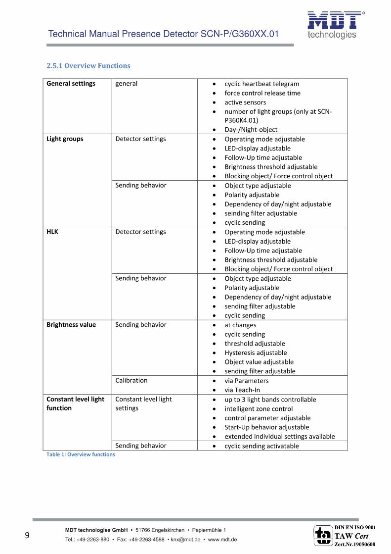
2.5.1 Overview Functions
General settings general cyclic heartbeat telegram
force control release time
active sensors
number of light groups (only at SCN-
P360K4.01)
Day-/Night-object
Light groups Detector settings Operating mode adjustable
LED-display adjustable
Follow-Up time adjustable
Brightness threshold adjustable
Blocking object/ Force control object
Sending behavior Object type adjustable
Polarity adjustable
Dependency of day/night adjustable
seinding filter adjustable
cyclic sending
HLK Detector settings Operating mode adjustable
LED-display adjustable
Follow-Up time adjustable
Brightness threshold adjustable
Blocking object/ Force control object
Sending behavior Object type adjustable
Polarity adjustable
Dependency of day/night adjustable
sending filter adjustable
cyclic sending
Brightness value Sending behavior at changes
cyclic sending
threshold adjustable
Hysteresis adjustable
Object value adjustable
sending filter adjustable
Calibration via Parameters
via Teach-In
Constant level light
function
Constant level light
settings
up to 3 light bands controllable
intelligent zone control
control parameter adjustable
Start-Up behavior adjustable
extended individual settings available
Sending behavior cyclic sending activatable Table 1: Overview functions

Technical Manual Presence Detector SCN-P/G360XX.01
MDT technologies GmbH • 51766 Engelskirchen • Papiermühle 1
Tel.: +49-2263-880 • Fax: +49-2263-4588 • [email protected] • www.mdt.de 10
2.6. Settings at the ETS-Software
Selection at the product database:
Manufacturer: MDT Technologies
Product family: Presence Detectors
Product type: Ceiling
Medium Type: Twisted Pair (TP)
Product name: addicted to the used type, e.g.: SCN-PM360K4.01, Presence Detector 360° Ceiling CL
4 sensors
Order number: addicted to the used type, e.g.: SCN-PM360K4.01
The available parameters depend to the chosen product type. The additional functions for the plus
variant are not shown at the normal push buttons.
2.7. Starting up
After wiring the allocation of the physical address and the parameterization of every channel follow:
(1) Connect the interface with the bus, e.g. MDT USB interface
(2) set bus power up
(3) Press the programming button at the device(red programming LED lights)
(4) Loading of the physical address out of the ETS-Software by using the interface(red LED goes
out, as well this process was completed successful)
(5) Loading of the application, with requested parameterization
(6) If the device is enabled you can test the requested functions(also possible by using the ETS-
Software)
Technical Manual Presence Detector SCN-P/G360XX.01
MDT technologies GmbH • 51766 Engelskirchen • Papiermühle 1
Tel.: +49-2263-880 • Fax: +49-2263-4588 • [email protected] • www.mdt.de 11
3 Communication objects
3.1 Overview
The communication objects are divided into the categories of the submenus.
The objects 0-12 are reserved for the lightgroups. The displayed objects and the length of the objects
change in accordance of the adjusted settings.
The object 14 is for the day/night switchover and can be activated via the general settings. Also the
object 15 – Prese e a e a ti ated i the ge eral setti gs. The o je ts a d refer to the menu brightness in which the specific settings for this object can be done. They contain the current
measured brightness value and the threshold value.
After these objects, the objects for the Teach-In function follows. The Teach-In function is for the
internal brightness compensation, especially for the constant light function.
Then the objects 20-28 follows, which are responsible for the constant light function. The object 29-
Output Heart eat a e para etrized i the ge eral setti gs.
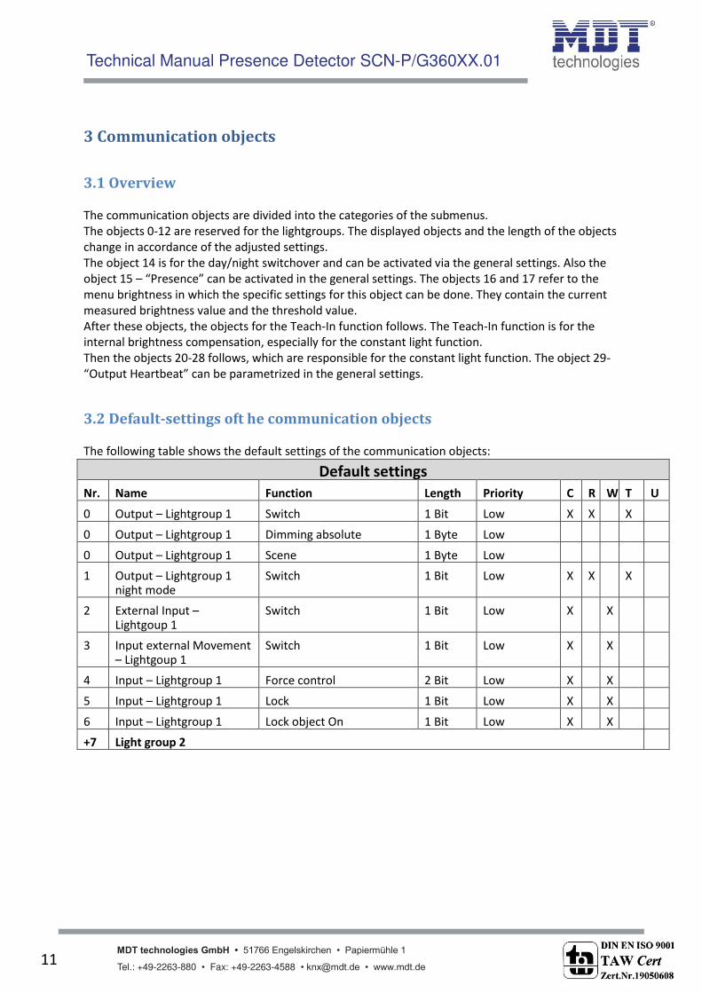
3.2 Default-settings oft he communication objects
The following table shows the default settings of the communication objects:
Default settings
Nr. Name Function Length Priority C R W T U
0 Output – Lightgroup 1 Switch 1 Bit Low X X X
0 Output – Lightgroup 1 Dimming absolute 1 Byte Low
0 Output – Lightgroup 1 Scene 1 Byte Low
1 Output – Lightgroup 1 night mode
Switch 1 Bit Low X X X
2 External Input – Lightgoup 1
Switch 1 Bit Low X X
3 Input external Movement – Lightgoup 1
Switch 1 Bit Low X X
4 Input – Lightgroup 1 Force control 2 Bit Low X X
5 Input – Lightgroup 1 Lock 1 Bit Low X X
6 Input – Lightgroup 1 Lock object On 1 Bit Low X X
+7 Light group 2
Technical Manual Presence Detector SCN-P/G360XX.01
MDT technologies GmbH • 51766 Engelskirchen • Papiermühle 1
Tel.: +49-2263-880 • Fax: +49-2263-4588 • [email protected] • www.mdt.de 12
7 Output – HLK Switch 1 Bit Low X X X
7 Output – HLK Dimming absolute 1 Byte Low X X X
7 Output – HLK Scene 1 Byte Low X X X
9 External Input – HLK Switch 1 Bit Low X X
10 Input external Movement – HLK
Switch 1 Bit Low X X
11 Input – HLK Force control 2 Bit Low X X
12 Input – HLK Lock 1 Bit Low X X
13 Input – HLK Lock object On 1 Bit Low X X
14 Input Day/Night Switch 1 Bit Low X X X
15 Presence Switch 1 Bit Low X X X
16 Threshold switch brightness
Switch 1 Bit Low X X X
17 Brightness value Brightness value 2 Byte Low X X X
18 Input TeachIn Start calibration 1 Bit Low X X
19 Input TeachIn Status absolute dimming value
1 Byte Low X X
20 Constant light Switch On/Off 1 Bit Low X X
21 Constant light Dimming relative 4 Bit Low X X
22 Constant light Dimming absolute 1 Byte Low X X
23 Constant light Force control 2 Bit Low X X
24 Constant light Lock object 1 Bit Low X X
25 Constant light Scene 1 Byte Low X X
26 Constant light Output dimming absolute main
1 Byte Low X X X
27 Constant light Output dimming absolute wall
1 Byte Low X X X
28 Constant light Output dimming absolute window
1 Byte Low X X X
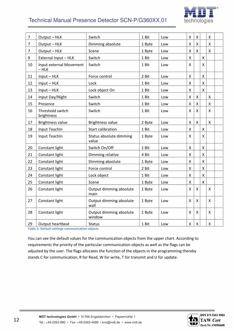
29 Output heartbeat Status 1 Bit Low X X X Table 2: Default settings communication objects
You can see the default values for the communication objects from the upper chart. According to
requirements the priority of the particular communication objects as well as the flags can be
adjusted by the user. The flags allocates the function of the objects in the programming thereby
stands C for communication, R for Read, W for write, T for transmit and U for update.
Technical Manual Presence Detector SCN-P/G360XX.01
MDT technologies GmbH • 51766 Engelskirchen • Papiermühle 1
Tel.: +49-2263-880 • Fax: +49-2263-4588 • [email protected] • www.mdt.de 13
4 Reference ETS-Parameter
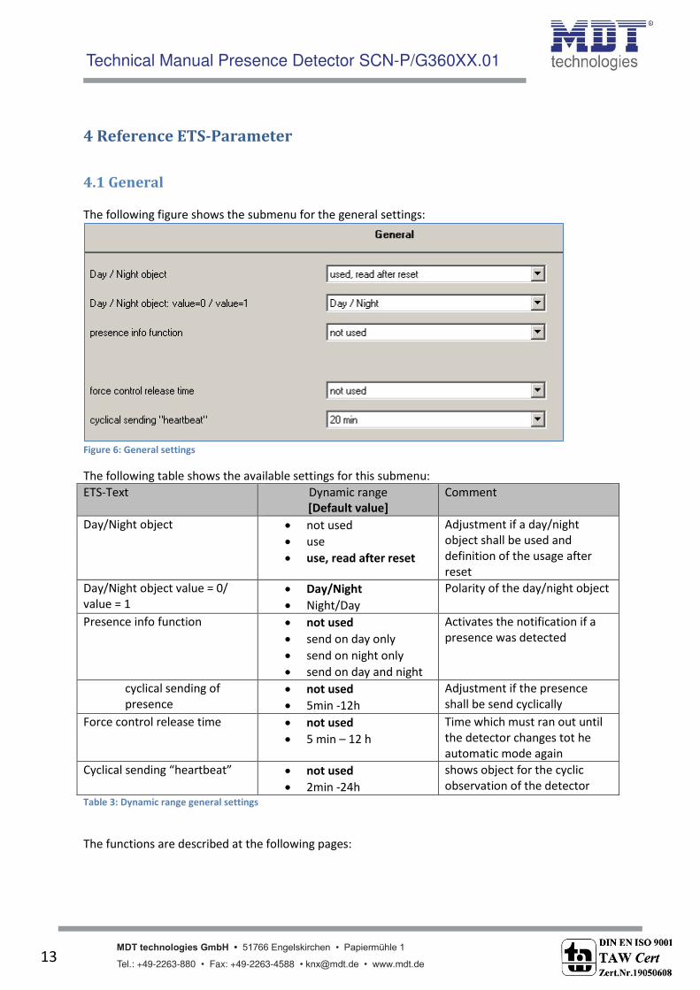
4.1 General
The following figure shows the submenu for the general settings:
Figure 6: General settings
The following table shows the available settings for this submenu:
ETS-Text Dynamic range
[Default value]
Comment
Day/Night object not used
use
use, read after reset
Adjustment if a day/night
object shall be used and
definition of the usage after
reset
Day/Night object value = 0/
value = 1
Day/Night
Night/Day
Polarity of the day/night object
Presence info function not used
send on day only
send on night only
send on day and night
Activates the notification if a
presence was detected
cyclical sending of
presence
not used
5min -12h
Adjustment if the presence
shall be send cyclically
Force control release time not used
5 min – 12 h
Time which must ran out until
the detector changes tot he
automatic mode again
C li al se di g heart eat not used
2min -24h
shows object for the cyclic
observation of the detector
Table 3: Dynamic range general settings
The functions are described at the following pages:

Technical Manual Presence Detector SCN-P/G360XX.01
MDT technologies GmbH • 51766 Engelskirchen • Papiermühle 1
Tel.: +49-2263-880 • Fax: +49-2263-4588 • [email protected] • www.mdt.de 14
Day/Night object
By using the day/night object, the presence detector can be switched into a day or night
mode. So extended functions in the submenus are available for configuring the presence
detector for a day and a night mode. For example different dimming levels can be adjusted
for day (e.g. 100%) and night (e.g. 30%) or a orientation light can be switched on via a second
switching object at night.
Presence info functiom
The presence info function can show an additional object for notificating presence. If the
day/night object is active, a relation between these both objects can be adjusted.
The presence info function can trigger an alarm function or being used for statistic purpose.
Force control release time
The force control release time defines the time wihich must expirate until the presence
detector changes from the manual mode into the automatic mode.
Cy li al sending heart eat
The fu tio C li al se di g heart eat sho s a o je t, hi h a e used for the cyclically observation of the presence detector. By using a superior control, it can be
supervised if the presence detector is still on the bus or not. Especially in complex systems,
the cancellation of lines or devices can be detected automatically.
Technical Manual Presence Detector SCN-P/G360XX.01
MDT technologies GmbH • 51766 Engelskirchen • Papiermühle 1
Tel.: +49-2263-880 • Fax: +49-2263-4588 • [email protected] • www.mdt.de 15
4.2 Light/ HCV
Up to 2 lightgroups (only at presence detectors with 4 sensors, SCN-P360K4 or SCN-P360D4) or one
lightgroup and one Heating, Cooling, Ventilation (HVC) can be switched by the presence detector.
Die nachfolgende Tabelle zeigt die möglichen Einstellungen:
ETS-Text Dynamic range
[Default value]
Comment
Selection Group One light group/zone
Two light groups/zones
One light group and
climate HCV
defines which groups shall be
switched from the presence
detector
Table 4: Selection Lightgroups
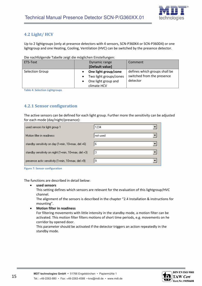
4.2.1 Sensor configuration
The active sensors can be defined for each light group. Further more the sensitivity can be adjusted
for each mode (day/night/presence):
Figure 7: Sensor configuration
The functions are described in detail below:
used sensors
This setting defines which sensors are relevant for the evaluation of this lightgroup/HVC
channel.
The alig e t of the se sors is des ri ed i the hapter 2.4 Installation & instructions for
mounting . Motion filter in readiness
For filtering movements with little intensity in the standby mode, a motion filter can be
activated. This motion filter filters motions of short time periods, e.g. movements on he
corridor by opened door.
This parameter should be activated if the detector triggers an action repeatedly in the
standby mode.

Technical Manual Presence Detector SCN-P/G360XX.01
MDT technologies GmbH • 51766 Engelskirchen • Papiermühle 1
Tel.: +49-2263-880 • Fax: +49-2263-4588 • [email protected] • www.mdt.de 16
Standby sensitivity on day/night
The presence detector is in the standby mode if no presence was detected and so the
detector is switched off. If the day/night object is active, different sensitivies can be adjusted
for the day and the night mode. A lower sensitivity prevents faulty activations.
Presence active sensitivity
In order that the presence detector detects every movement at the presence mode (=
detector has detected a motion and is switched on), a higher sensitivity can be adjusted for
this case.
The following figure demonstrates the motion sensitivity:
Figure 8: Motion sensitivity
The upper figure shows the effect of the different settings to the motion sensitivity. A lower motion
sensitivity causes a larger range of tolerance. A higher motion sensitivity causes a smaller range of
tolerance. Every infrared signal (dotted line), which is out of the range of tolerance is detected as
motion.
For configuring the detector in a way that small signals, e.g. passing a door, not cause an activation,
the sensitivity must be set to a ower value, so the range of tolerance is set to a higher value.

Technical Manual Presence Detector SCN-P/G360XX.01
MDT technologies GmbH • 51766 Engelskirchen • Papiermühle 1
Tel.: +49-2263-880 • Fax: +49-2263-4588 • [email protected] • www.mdt.de 17
4.2.2 Detector configuration
The following illustration shows the available settings for detector at a light group:
Figure 9: Settings light group
At the HVC Mode the right ess treshold is repla ed the para eter u er of o itori g ti e slot a d le gth of o itori g ti e slot s :
Figure 10: Settings HVC

Technical Manual Presence Detector SCN-P/G360XX.01
MDT technologies GmbH • 51766 Engelskirchen • Papiermühle 1
Tel.: +49-2263-880 • Fax: +49-2263-4588 • [email protected] • www.mdt.de 18
The following chart shows the avalibale settings for these parameters:
ETS-Text Dynamic range
[Default value]
Comment
Operating mode of detector fully automatic
semi automatic
Adjustment oft he operating
mode
LED green
(only at light group 1&2)
Off
show movement
show movement on day
only
Definition oft he switching
behavior oft he green LED
Follow-up time 1s – 4h
[5 min]
Definition of the On-period
Lower active brightness
treshold (only at light groups)
0-2000 Lux
[400 Lux]
Adjustment below the detctor
shall work; the sensor is not
active at greater brightness
values
Upper disable brightness
treshold (only at light groups)
not used, 10-2000 Lux Adjustment at which upper
value the detector is disabled
Number of monitoring time
slots
(only at HCV)
0-32
[3]
Definition how much motions
must be detected before the
presence detecor switches on
Length of monitoring time
slot
(only at HCV)
0-3000s
[30s]
Adjustment oft he length of
the monitoring time slot
Force or lock object Force control object
Lock object universal
Lock object universal and
force object ON
Adjustment if a force control
object or a lock object shall be
used
Table 5: Setting detector
The parameters are described in detail as follows:
Operating mode
The operating mode is divided into fully automatic and semi automatic. So the presence
detector can be configured for greater rooms as Maser/Slave. The Master/Slvae mode is
described in detail in an extra chapter.
fully automatic
If the presence detector is configured as fully automatic, every detected presence
causes power-on of the output.
semi automatic
At the semi automatic mode, the output is only switched on if the detector detects a
presence and the object External Input – light group 1/2 /HCV receives an on-signal
at the same time.

Technical Manual Presence Detector SCN-P/G360XX.01
MDT technologies GmbH • 51766 Engelskirchen • Papiermühle 1
Tel.: +49-2263-880 • Fax: +49-2263-4588 • [email protected] • www.mdt.de 19
Follow-up time
The follow-up time defines the power-on time. The detector switches on at detected
presence until the adjusted follow-up time runs out.
Sensor activation/-deactivation
The sensor activation/deactivation is only available at light groups. By using this setting, the
dete tor a get a deter i ed orki g zo e. The para eter Lower active brightness
threshold defi es the brightness threshold below the detector works as normal presence
detector. If the brightness is higher than this threshold, no motion will be detected. The
sensor is not switched off upper this brightness threshold. This behavior can be achieved by
usi g the para eter Upper disa le right ess treshold . This alue should ot e adjusted to low, because this could effect a steady switching of the output.
Monitoring time slots
The Monitoring time slots are only available fort he HCV channel. This setting causes that a
longer detzection is necessary for switching the detector on. For switching the channel on, in
every time slot a at least one motion must be detected.
Force control /Lock object
The object can be used as well as force conbtrol object or as lock object. The force control
object has 3 different states:
Force control ON (control = 1, value = 1)
At this mode an on-command is sent to the output. The evaluation is stopped and
the follow-up time starts. If no command is received at the force control object after
the follow-up time, the detector switches back into the normal mode.
Force control OFF (control = 1, value = 0)
At this command an off-command is sent to the output. The evaluation is stopped
and the follow-up time starts. If no command is received at the force control object
after the follow-up time, the detector switches back into the normal mode.
Force control AUTO (control = 0 value = 0)
After sending this command, the normal mode of the detector starts.
The lock object can be used with the following settings for the activation and deactivation:
Force control ON
Same functionality as described at Force Control ON.
Force control OFF
Same functionality as described at Force Control OFF.
Automatic mode
The detector switches again tot he automatic mode.
Lock (actual state)
The detector is locked in the current state.
Additional a second lock object can be shown fort he lock object, the lock object ON. This
object switches the output continuous ON.

Technical Manual Presence Detector SCN-P/G360XX.01
MDT technologies GmbH • 51766 Engelskirchen • Papiermühle 1
Tel.: +49-2263-880 • Fax: +49-2263-4588 • [email protected] • www.mdt.de 20
4.2.3 Communication object settings
The following chart shows the available settings for the communication objects of the light
groups/HCV group:
Das nachfolgende Bild zeigt die Einstellmöglichkeiten für die Kommunikationsobjekte für Licht/HLK:
Figure 11: Communication object settings light groups/HCV group

Technical Manual Presence Detector SCN-P/G360XX.01
MDT technologies GmbH • 51766 Engelskirchen • Papiermühle 1
Tel.: +49-2263-880 • Fax: +49-2263-4588 • [email protected] • www.mdt.de 21
The following table shows the available settings for these parameters:
ETS-Text Dynamic range
[Default value]
Comment
Object type for output - light Switching
Dimming absolute
Scene
Adjustment oft he switching
object of the light group
output
Object type for output –
climate(HCV)
Switching
Send value
Scene
Adjustment oft he switching
object of the HCV output
Object value on day
for On
On/Off
0-100% [100%]
Scene 1-32 [5]
Adjustment of the sending at
this state
Object value on day
for Off
On/Off
0-100% [0%]
Scene 1-32 [6]
Adjustment of the sending at
this state
Object value on night
for On
On/Off
0-100% [100%]
Scene 1-32 [7]
Adjustment of the sending at
this state
Object value on night
for Off
On/Off
0-100% [0%]
Scene 1-32 [8]
Adjustment of the sending at
this state
Use 2. switch object at night
(only at light groups and
object type switch)
Yes
No
shows a second switching
object fort he night mode, e.g.
for switching an orientation
light
Standby/Orientationlight
(only at light groups and
object type dimming
absolute)
used
not used
Activation of a standby
function, which starts after
expiration of the follow-up
time
Standby time on
day/night
no delay
1s – 60min
Adjustment of the duration of
the standby time
Standby dimming
value on day/Night
1- 100%
[1%]
Adjustment of the dimming
value for the standby function
Switching object send at
(only at object type switching)
send nothing
only ON
only OFF
ON and OFF
Sendefilter für das
Ausgangsobjekt
Cyclical sending of object
value ON
not used
1min – 60min
Activation of cyclic sending
External input reacts on send nothing
only ON
only OFF
ON and OFF
Input filter for the object
External Input – light group
1/2/HCV
Idle time after swtitch off 1s – 60s
[10s]
Time, which must expire after
swiotching off for detecting a
new movement Table 6: Communication object setting presence function

Technical Manual Presence Detector SCN-P/G360XX.01
MDT technologies GmbH • 51766 Engelskirchen • Papiermühle 1
Tel.: +49-2263-880 • Fax: +49-2263-4588 • [email protected] • www.mdt.de 22
The following chart shows the relevant communication objects for the first light group:
Number Name Length Usage
0 Output – light group 1 1 Bit/
1Byte
Output for the first light group; Length and type
depends to the parameter Object type for output
1 Output – light group 1
night mode
1 Bit Output for the orientation light at night mode
2 External Input – light group
1
1 Bit External input for Push Buttons/Indication object
of an actuator for switching the light
3 Input external movement –
light group 1
1 Bit External input for second detector
4 Force control 2 Bit Force control object; switches the detector as
described above
4 Lock 1 Bit Lock object; switches the detector as the
adjusted settings
5 Lock object ON 1 Bit Lock object, which switches the detector on with
a 1-command Table 7: Communication objects light
If a second light group is activated, the same communication objects with the same functionality are
shown.
The following table shows the relevant communication objects for a HCV channel:
Number Name Length Usage
7 Output – climate (HCV) 1 Bit/
1Byte
Output for the HCV group; Length and type
depends to the parameter Object type for output
8 External Input – climate
(HCV)
1 Bit External input for Push Buttons/Indication object
of an actuator for switching the HCV group
9 Input external movement –
climate (HCV)
1 Bit External input for second detector
10 Force control 2 Bit Force control object; switches the detector as
described above
11 Lock 1 Bit Lock object; switches the detector as the
adjusted settings
12 Lock object ON 1 Bit Lock object, which switches the detector on with
a 1-command Table 8: Communication objects HCV

Technical Manual Presence Detector SCN-P/G360XX.01
MDT technologies GmbH • 51766 Engelskirchen • Papiermühle 1
Tel.: +49-2263-880 • Fax: +49-2263-4588 • [email protected] • www.mdt.de 23
4.3 Brightness
The following figure shows the available settings for the brightness detection:
Figure 12: Settings brightness
The following table shows the available settings for these parameters:
ETS-Text Dynamic range
[Default value]
Comment
Send brightness on change of not used
20 Lux – 1800 Lux
[50 Lux]
Minimum rate of change for
sending the current brightness
Cyclical sending of light value not used
5s – 30min
Adjustment of a determined
time span for sending the
current brightness
Value for switching the
threshold switch
60Lux – 1000 Lux
[300 Lux]
Adjustment of the threshold
for switching = defined
threshold for ON
Hysteresis of threshold switch 5 Lux– 200 Lux
[30 Lux]
Distance between value for
switching ON and OFF => Off-
threshold = Value for
switching the threshold switch
- Hysteresis
Object value on day for On ON
OFF
Adjustment of the polarity
Object value on night for On ON
OFF
Adjustment of the polarity
Object value for off ON
OFF
Adjustment of the polarity

Technical Manual Presence Detector SCN-P/G360XX.01
MDT technologies GmbH • 51766 Engelskirchen • Papiermühle 1
Tel.: +49-2263-880 • Fax: +49-2263-4588 • [email protected] • www.mdt.de 24
Send on day only send nothing
only ON
only OFF
ON and OFF
Sending filter at day mode
Send on night only send nothing
only ON
only OFF
ON and OFF
Sending filter at night mode
Table 9: Settings brightness
At the Menu brightness the sending behavior for the measured brightness value can be adjusted. The
measured brightness value can be send at determined changes or at determined times.
Additional a treshold can be defined. This threshold can be adjusted with a hysteresis for preventing
of frequently switching. The effect of the hysteresis shows the following figure:
Figure 13: Hysteresis brightness threshold
Further more the polarity and the sending behavior can be adjusted by the parameters Object value
for da / ight/off a d “e d o da / ight o l .
The following table shows the relevabt communication objects:
Number Name Length Usage
16 Threshold switch
brightness
1 Bit sends the adjusted value at exceedance or
undercut
17 Brightness value 2 Byte measured brightness value Table 10: Communication objects brightness

Technical Manual Presence Detector SCN-P/G360XX.01
MDT technologies GmbH • 51766 Engelskirchen • Papiermühle 1
Tel.: +49-2263-880 • Fax: +49-2263-4588 • [email protected] • www.mdt.de 25
4.4 Calibration brightness value
The following figure shows the available settings for the calibration oft h e brightness value:
Figure 14: Calibration brightness value
The following chart shows the availbale settings for this parameter:
ETS-Text Dynamic range
[Default value]
Comment
Offset brightness [Lux] -100 – 100
[0]
Increasing/Decreasing by the
adjusted value
Room reflection factor 1
0,7 very high
0,5 high
0,4 medium
0,3 low
0,25 low
0,2 very low
Reflection factor of the
environment;
indicates how much light is
reflected bach (1=100% /
0=0%)
TeachIn brightness value[Lux] 200-1000
[450]
Comparison value for external
import
Use TeachIn value at
application download
hold TeachIn values
Use factory default values
Adjustment if the presence
detector shall keep the
TeachIn values after a
download or use the factory
default values Table 11: Calibration brightness value
Consecutively the parameters are described in detail:
Offste brightness
The correction of the brightness value is a simple offset of the measured brightness value. So
at a value of -50, the measured value is reduced by 50. By this setting the presence detector
would send at a value 0f 400 at measured value of 450.

Technical Manual Presence Detector SCN-P/G360XX.01
MDT technologies GmbH • 51766 Engelskirchen • Papiermühle 1
Tel.: +49-2263-880 • Fax: +49-2263-4588 • [email protected] • www.mdt.de 26
Reflection factor
The reflection factor indicates how much of the emitted light is reflected by the environment
back to the light source. The value 1 means that 100% of the emitted light is reflected back to
the light source. At dark floors, a value of 0,25, is recommended.
Die nachfolgende Tabelle dient als Orientierung um den Reflexionsfaktor an Ihren Raum
anzupassen:
Metalle, Farbanstriche, Baustoffe Reflexionsgrad
Aluminium, hochglänzend 0,80-0,85
Aluminium, mattiert 0,50-0,70
Stahl, poliert 0,50-0,60
Weiß 0,70-0,80
Hellgelb 0,60-0,70
Hellgrün, hellrot, hellblau, hellgrau 0,40-0,50
beige, ocker, orange, mittelgrau 0,25-0,35
Dunkelgrau, dunkelrot, dunkelblau 0,10-0,20
Putz, weiß 0,70-0,85
Gips 0,70-0,80
Beton 0,30-0,50
Ziegel, rot 0,10-0,20
Glas, klar 0,05-0,10
Table 12: List of reflection factors
If no TeachIn is performed, the measured brightness can be corrected with the reflection factor. If a
TeachIn is performed, the brightness value is corrected automatically. The TeachIn must not be
changed after the TeachIn process.
The TeachIn process for presence detectors with constant level light or without constant level light is
different in execution and effect.
Especially at presence detectors with constant level light, the TeachIn should be performed for
improving the accurateness of the constant level light.
The process for the TeachIn with constant level light (SCN-P360K3.01 und SCN-P360K4.01) is
described in the following chapter, the TeachIn process for presence detector without constant level
light (SCN-P360D3.01 und SCN-P360D4.01) is descrbed in the next but one.

Technical Manual Presence Detector SCN-P/G360XX.01
MDT technologies GmbH • 51766 Engelskirchen • Papiermühle 1
Tel.: +49-2263-880 • Fax: +49-2263-4588 • [email protected] • www.mdt.de 27
4.4.1 Approach at Teach-In with constant level light
For using the whole advantages oft he intelligent constant light control, the presence detector must
be adjusted once via the Teach-In process. Therefore a luxmeter is needed.
The approach is as follows:
1. Adjust the para eter Tea hI right ess alue to the desired right ess alue. Mostly 400-500 Lux are used.
2. Adjust the Para eter Use Tea hI alue at appli atio do load fro Use fa tor default
values to hold TeachIn values .de ge ü s hte Wert. 3. Make the desired settings fort he constant light function. (have a look at chapter
4.5)Aktivieren Sie die Regelung mit den gewünschten Einstellungen
4. Connect the communication objects fort he different light groups with the objects oft he
dimming actuator
5. Co e t the o je t -“tatus a solute di i g alue ith the status o je t of the dimming actuator for the light group in the middle.
6. Co e t the o je t -Cali ratio start ith a e group address, if the ali ratio shall e activated via the ETS (Group monitor) or with a push button.
7. Download the application.
8. The room must be darkened or the measurement must be performed in the twilight. The
presence detector teaches the brightness and dimming values via the Teach-In function. If
the Teach-In is performed at day-/sunlight the measurement is disturbed and the saves
wrong values.
9. Activate the Teach-In function by sending a logical 0 to the object 18. The green LED in the
presence detector starts flashing with a 1s rhythm. Sending a logical 0 again causes an
interruption of the Teach-In process.
10. Change the brightness value by sending dimming values (absolute or relatrive) until the
Luxmeter swhows the adjusted value (TeachIn brightness value) at the desired height.
11. Now send a logical 1 to the object 18. The red and green LED flashes alternating.
12. The presence detector adjusts now the brightness measurement, teaches the appropriated
dimming value and learns the brightness value at different dimming values.
13. After successful end of the Teach-In process, the green LED flashes fast for 10 seconds. The
control is started again automatically and adjusts the brightness to the reference value. If an
error occurs, the process is aborted and the red LED flashes fast for 10 seconds. This can
occur if for example no valid dimming value is available (status). Check point 5 and start the
process again.
14. If the para eter use s it h o di i g alue is adjusted to al ulate s it h o alue , the switch on value is calculated automatically now.

Technical Manual Presence Detector SCN-P/G360XX.01
MDT technologies GmbH • 51766 Engelskirchen • Papiermühle 1
Tel.: +49-2263-880 • Fax: +49-2263-4588 • [email protected] • www.mdt.de 28
The behavior of the LED and its meaning can be extracted from the chart below:
LED behavior State
green LED flashes slowly TeachIn is activated; detector is at the TeachIn
modeZ
grenn and red LED flash
alternating
TeachIn process is running
green LED flashes fast for
10 secleuchtet
TeachIn process is completed succesful
red LED flashes fast for 10
secleuchtet
TeachIn process causes an error
Table 13: LED behaviour at Teach-In
The following chart shows the relevant communication objects:
Number Name Length Usage
18 Calibration start 1 Bit starts the alignment via Teach-In
19 Status absolute dimming
value
1 Byte must be connected to the status value of the
dimming actuator Table 14: Communication objects Teach-In
4.4.2 Approach at Teach-In without constant level light
The TeachIn process at presence detectors without constant level light is for correcting the measured
value.
The process is as described below:
1. Adjust the para eter Tea hI right ess alue to the desired right ess alue. The best way doing the Teach-In process is to darken the room and switch the artificial lights
on. Now the brightness must be measured via a luxmeter and the measured value must be
set for the parameter Tea hI right ess alue .
2. Adjust the Para eter Use Tea hI alue at appli atio do load fro Use fa tor default
values to hold TeachIn values .de ge ü s hte Wert. 3. Co e t the o je t -Cali ratio start ith a e group address, if the ali ratio shall e
activated via the ETS (Group monitor) or with a push button.
4. Download the application.
5. Activate the Teach-In function by sending a logical 1 to the object 18.
6. Now the presence detector has adopted the adjusted value as new measurand and corrects
its measurement from now according to the TeachIn value.

Technical Manual Presence Detector SCN-P/G360XX.01
MDT technologies GmbH • 51766 Engelskirchen • Papiermühle 1
Tel.: +49-2263-880 • Fax: +49-2263-4588 • [email protected] • www.mdt.de 29
4.5 Constant level light
By using the new proportional Master/Slave Constant level light regulation, the light of the room can
be controlled intelligent so that outer light has no influence to the light in the room. Up to three light
groups can be controlled in a way that the brightness all over the room has the same level indepent
of outer infunces of the sun or other lights. The light control helps saving energy.
Notice: The light groups should be set to one light group or one light group and HCV. A Constant level
light regulation of to light groups/zones is not reasonalble.
The following figure shows the principal oft he constant level light control:
Figure 15: Overview proportional zone control
4.5.1 General settings/ Main principle regulation
The following figure shows the available settings for the general settings of the constant level light
regulation:
Figure 16: General settings constant level light regulation

Technical Manual Presence Detector SCN-P/G360XX.01
MDT technologies GmbH • 51766 Engelskirchen • Papiermühle 1
Tel.: +49-2263-880 • Fax: +49-2263-4588 • [email protected] • www.mdt.de 30
The following table shows the available settings for configuring the constant level light regulation:
ETS-Text Dynamic range
[Default value]
Comment
Constant light control disabled
enabled
Activation/Deactivation of the
constant level light regulation
Control out sunlight normal
few
very few
defines the influence of the
solar radiation to the
regulation
Selection light band 1 light group
light group main + wall
light group main + window
light group main + wall +
window
Selection of the light bands,
which shall be controlled
Influence proportional wall
control
no change (x 1)
very low (x 1,2)
low (x 1,4)
medium (x 1,6)
high (x 1,8)
very high (x 2)
defines the influence of the
light group wall to the
constant level light regulation
Influence proportional
window control
no change (x 1)
very low (x 0,9)
low (x 0,8)
medium (x 0,7)
high (x 0,6)
very high (x 0,5)
defines the influence of the
light group window to the
constant level light regulation
Table 15: General settings of the Constant level light regulation
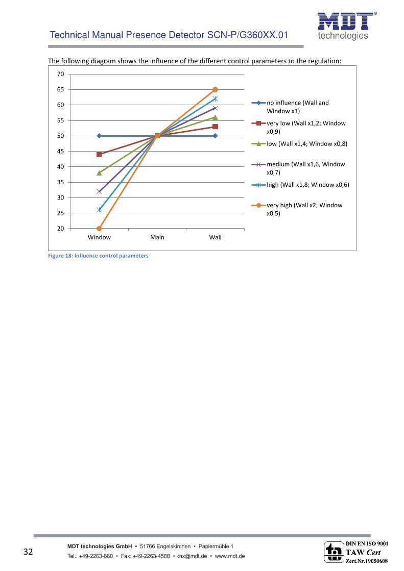
The parameter I flue e proportio al zo e o trol i di ates the i flue e of the light group to the o sta t light o trol. The setti g o ha ge s it hes the li earit of the regulation off and all
light groups light always ith the sa e right ess. The setti g er high , at i do a d at wall) deactivates means that the difference between the absolute dimming values of wall and
window is very high.
If a room shall be controlled via the constant level light control, it is recommended to use the
TeachIn function to get best results.
The influences of the light groups wall and window must be adapted to the specific conditions in the
room. Simplified you can say as larger the room as greater must be the difference of the controlling
parameter to 1. But is tis recommended to check the parameters always locally and adapt them if
necessary.
The regulatio a e alig ed ia the para eter Co trol out su light . If the prese e dete tor compensated solar radiation too strong, the value of this parameter should be set to few or very few.
An alternative method is installing the presence detector more into the middle of the room.

Technical Manual Presence Detector SCN-P/G360XX.01
MDT technologies GmbH • 51766 Engelskirchen • Papiermühle 1
Tel.: +49-2263-880 • Fax: +49-2263-4588 • [email protected] • www.mdt.de 31
The following diagram shows the dimming behavior fort he 3 light groups at different solar
irradiation. The TeachIn value is achieved, at this example, at an absolute dimming value of 80% with
450Lux. The influences are both set to medium.
Figure 17: Behavior proportional zone control
The diagram shows that the light at the window is dimmed more than the light at the main band and
the wall.
If the solar irradiation decreases, all light bands will be dimmed again to 80%.
If the illumination is set from e.g. 450Lux to 300Lux (via relative dimming, absolute dimming or
scene), the comprehension of the control factor will automatically set at the right dimming value. In
this case, e.g at 50%. Without solar irradiation the three light bands regulate to 300 Lux with a
dimming value of 50%. With solar irradiation, the dimming values below 50% shift appropriate.
By using the new proportio al Master/“la e Co sta t le el light regulatio all disadvantages of the
o er iall a aila le Offset Master/“la e Co sta t le el light regulatio ith onstant offset are
fixed.
0,0
10,0
20,0
30,0
40,0
50,0
60,0
70,0
80,0
90,0
100,0
Window Main Wall
Dim
min
g
va
lue
s
Technical Manual Presence Detector SCN-P/G360XX.01
MDT technologies GmbH • 51766 Engelskirchen • Papiermühle 1
Tel.: +49-2263-880 • Fax: +49-2263-4588 • [email protected] • www.mdt.de 32
The following diagram shows the influence of the different control parameters to the regulation:
Figure 18: Influence control parameters
20
25
30
35
40
45
50
55
60
65
70
Window Main Wall
no influence (Wall and
Window x1)
very low (Wall x1,2; Window
x0,9)
low (Wall x1,4; Window x0,8)
medium (Wall x1,6, Window
x0,7)
high (Wall x1,8; Window x0,6)
very high (Wall x2; Window
x0,5)

Technical Manual Presence Detector SCN-P/G360XX.01
MDT technologies GmbH • 51766 Engelskirchen • Papiermühle 1
Tel.: +49-2263-880 • Fax: +49-2263-4588 • [email protected] • www.mdt.de 33
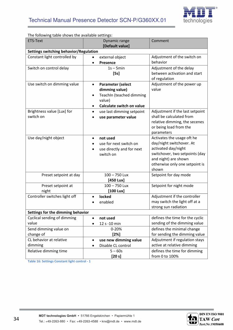
4.5.2 Available settings
The following figure shows the available specific settings for the constant level light control:
Figure 19: Available settings constant light control
Technical Manual Presence Detector SCN-P/G360XX.01
MDT technologies GmbH • 51766 Engelskirchen • Papiermühle 1
Tel.: +49-2263-880 • Fax: +49-2263-4588 • [email protected] • www.mdt.de 34
The following table shows the available settings:
ETS-Text Dynamic range
[Default value]
Comment
Settings switching behavior/Regulation
Constant light controlled by external object
Presence
Adjustment of the switch on
behavior
Switch on control delay 1s – 5min
[5s]
Adjustment of the delay
between activation and start
of regulation
Use switch on dimming value Parameter (select
dimming value)
TeachIn (teached dimming
value)
Calculate switch on value
Adjustment of the power up
value
Brightness value [Lux] for
switch on
use last dimming setpoint
use parameter value
Adjustment if the last setpoint
shall be calculated from
relative dimming, the secenes
or being load from the
parameters
Use day/night object not used
use for next switch on
use directly and for next
switch on
Activates the usage oft he
day/night switchover. At
activated day/night
switchover, two setpoints (day
and night) are shown
otherwise only one setpoint is
shown
Preset setpoint at day 100 – 750 Lux
[450 Lux]
Setpoint for day mode
Preset setpoint at
night
100 – 750 Lux
[100 Lux]
Setpoint for night mode
Controller switches light off locked
enabled
Adjustment if the controller
may switch the light off at a
strong sun radiation
Settings for the dimming behavior
Cyclical sending of dimming
value
not used
12 s -10 min
defines the time for the cyclic
sending of the dimming value
Send dimming value on
change of
0-20%
[2%]
defines the minimal change
for sending the dimming value
CL behavior at relative
dimming
use new dimming value
Disable CL control
Adjsutment if regulation stays
active at relative dimming
Relative dimming time 5 – 60s
[20 s]
defines the time for dimming
from 0 to 100% Table 16: Settings Constant light control - 1

Technical Manual Presence Detector SCN-P/G360XX.01
MDT technologies GmbH • 51766 Engelskirchen • Papiermühle 1
Tel.: +49-2263-880 • Fax: +49-2263-4588 • [email protected] • www.mdt.de 35
ETS-Text Dynamic range
[Default value]
Comment
Settings standby/orientation light
Standby/Orientationlight not used
used
Setting if the light shall stay on
after switching off
Standby setpoint 100 – 750 Lux
[100 Lux]
Value for the standby mode
Standby time 1s – 60min
[15s]
Length of standby mode
Settings lock object
Force control active Yes
No
activates the force control
Lock object
value = 1
off
on (100%)
no change (hold value)
select value
Adjustment of the action at
activation
Value set
ur ei „Wert ei stell ar
0-100%
[0%]
defines the value for active
force control
Lock object
value = 0
off
on (100%)
no change (hold value)
restore previous state
Adjustment of the action at
deactivation
Table 17: Settings Constant light control - 2
The parameters are described below:
Adjustment switching behavior/Regulation
The general settings for the constant level light regulation can be done here.
The para eter Co sta t light o trolled defi es hethter the o sta t light shall e switched via presence or an external object, which could be connected to push button, etc.
The para eter Use s it h o di i g alue defi es the start-up value of the regulation. It
can be calculated directly by the internal calculating routine or power up with a fixed value.
Also the time between powering up and starting calculation can be defined.
The para eter Bright ess alue [Lu ] for s it h o defi es if the regulatio shall ork ith the parameterized value or the last setpoint, which can be set by a relative or absolute
dimming value or via the scene function.
Further more the regulation can be parameterized with different values for day and night via
the para eter Use da / ight o je t . The para eter „Co troller s it hes light off defi es if the o troller s it hes the light off at a strong sun radiation. If the parameter is set to locked, the output will not be set to 0% even
if the sun radiation is strong enough. The output is set to a minimum value. This setting is
very useful in offices or workrooms, because a switch-off of the lights is felt as annoying for
most people. However, the energy saving aspects is still valid, because at dimming to e.g.
20%, 80% of the normal energy consumption is saved.

Technical Manual Presence Detector SCN-P/G360XX.01
MDT technologies GmbH • 51766 Engelskirchen • Papiermühle 1
Tel.: +49-2263-880 • Fax: +49-2263-4588 • [email protected] • www.mdt.de 36
Settings dimming behavior
The dimming value can be sent as well cyclical as at a fixed percental rate of change.
The para eter CL behavior at relative dimming defi es if the regulatio shall e s it hed off at relative dimming or work with the new value.
Settings standby/orientation light
The standby/orientation light defines shading of the room after cutout of the constant light
control. That means, that the controller does not switch the lights off, but switches to the
adjusted value.
Settings lock object
This parameter activates an additional lock object, which locks the constant level light
control and switches the output in a fixed state.
The following states are available:
o Off: The output is switched off (0%).
o On: The output is switched on (100%):
o No change: The current absolute value is hold.
o Select value(only at lock): The adjusted absolute value is called.
o Restore previous state(only at unlock): The absolute value which had the constant
light before locking is called again.
The following table shows the relevant communication objects for the constant ligh control:
Number Name Length Usage
20 Switch on/off 1 Bit external object for activating the regulation
21 Dimming relative 4 Bit manual adjustment of the current brightness
22 Dimmin absolute 1 Byte Adjustment current brightness of new absolute value
24 Lock object 1 Bit Locking the regulation
26 Output dimming absolute main
1 Byte Output for main group
27 Output dimming absolute wall
1 Byte Output for wall group
28 Output dimming absolute window
1 Byte Output for window group
Table 18: Communication objects constant light control

Technical Manual Presence Detector SCN-P/G360XX.01
MDT technologies GmbH • 51766 Engelskirchen • Papiermühle 1
Tel.: +49-2263-880 • Fax: +49-2263-4588 • [email protected] • www.mdt.de 37
4.5.3 Scenes
The following figure shows the available settings for the scene function of the constant light control:
Figure 20: Scene function constant light control
The constant light control can get a new setpoint via the scene function, by sending the scene
number at the communication object for the scenes. The regulation takes the adjusted value as new
setpoint.
The following table shows the communication object for the setpoint of the scene function:
Number Name Length Usage
25 Scene 1 Bit Reading in of the scene Table 19: Communication object scene function
4.5.4 Approach at Start-Up
For activating the constant level light regulation, the following steps are necessary:
1. Parameterizing the presence detector as desired including TeachIn function (Submenu
Calibration brightness value), Constant light and General.
2. Connecting of all necessary objects
3. Run TeachIn function as described in 4.4.1 Approach at Teach-In
4. Now the constant light control is adjusted completely

Technical Manual Presence Detector SCN-P/G360XX.01
MDT technologies GmbH • 51766 Engelskirchen • Papiermühle 1
Tel.: +49-2263-880 • Fax: +49-2263-4588 • [email protected] • www.mdt.de 38
4.6 Master/Slave
4.6.1 Light groups
In larger rooms often more than one presence detector is required. For detecting presence all over
the room, presence detectors must be allocated in the whole room. But also in this case a detected
presence shall cause always the same settings independent of the place of detection. In this case one
detector operates as Master and a arbitrary number of presence detectors work as Slave.
The setti gs for the Master/“l ae ode a e do e i the su e u light groups . The Slaves must be configured as follows:
Adjustment to fully automatic (every movement shall be sent)
Set follow-up time tot he same value as the Master
Activate cyclic sending for the output
o Parameter: Cyclical sending of object value ON
o Guidance value: 1min, at greater Follow-up time, e.g. 15min, the cyclical sending can
be set up to a greater value, e.g. 5min, for minimzing the bus load
Bright ess alue for lo er a ti e right ess threshold to a i u alue
Bright ess alue for upper disable right ess threshold to not used
The Master can be parameterized as desired as fully automatic or semi automatic.
For the follow-up time a value of 10 min is recommended.
The connection of the objects must be done as follows:
all output objects of the Slaves (object 0) must be connected withe the object external
movement (object 3) of the Master.
Now the Master evaluates every degtected presence of itself and the detected presence of every
Slave and switches the light according to its settings, regardless which presence detector has
detected a movement.
4.6.2 HVC
The Master/Slave circuit can alos be used for HCV channels. In this case, the slave must be adjusted
in the same way as the slaves for the light groups. But the settings for the brightness values have not
to be applied. The settings for the monitoring time slots must be maded according to the individual
desires.
The connection of the communication objects must be done as follows:
All output objects of the slaves (object 0) must be connected to the object external
movement (object 10) of the Master.

Technical Manual Presence Detector SCN-P/G360XX.01
MDT technologies GmbH • 51766 Engelskirchen • Papiermühle 1
Tel.: +49-2263-880 • Fax: +49-2263-4588 • [email protected] • www.mdt.de 39
4.7 Other/ Examples of use
At this chapter, examples of use/areas of use for the presence detector are given. The examples are
only suggestions and if necessary they must be adapted to the actual state.
4.7.1 Blackboard light via second light group
For switching the light in a classroom according to its specific use, a presence detectore is used for
switching the room light. But often a second light at the blackboard is necessary for which a second
light group can be used. This light must also switch on request and shall switch off automatically,
when the teacher/lecturer leaves the area before the blackboard again. For realizing this scenario in
small rooms, only one presence detector is needed. At greater rooms a second presence detector,
which is used as Slave can be useful.
The first presence detector for the blackboard light must be parameterized as follows:
Selection of lightgroups: 2 light groups
1. light group:
Operating mode: fully automatic
Active sensors: 1234
other parameters: according to usage
2. light group:
Operating mode: semi automatic
Active sensors: 1234
other parameters: according to usage
The output objects of the light group must be connected to the switching objects of these light
groups.
The o je t e ter al i put of the se o d light group ust e o e ted to the push utto , hi h sends the requirement for the blackboard light. The push button must send an 1-signal to the object.
Technical Manual Presence Detector SCN-P/G360XX.01
MDT technologies GmbH • 51766 Engelskirchen • Papiermühle 1
Tel.: +49-2263-880 • Fax: +49-2263-4588 • [email protected] • www.mdt.de 40
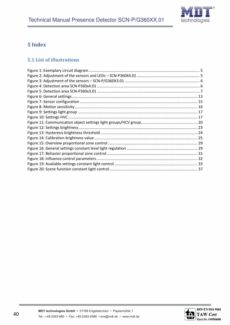
5 Index
5.1 List of illustrations
Figure 1: Exemplary circuit diagram ........................................................................................................ 5
Figure 2: Adjustment of the sensors and LEDs – SCN-P360X4.01 ........................................................... 5
Figure 3: Adjustment of the sensors – SCN-P/G360X3.01 ...................................................................... 6
Figure 4: Detection area SCN-P360x4.01 ................................................................................................ 6
Figure 5: Detection area SCN-P360x3.01 ................................................................................................ 7
Figure 6: General settings ...................................................................................................................... 13
Figure 7: Sensor configuration .............................................................................................................. 15
Figure 8: Motion sensitivity ................................................................................................................... 16
Figure 9: Settings light group ................................................................................................................ 17
Figure 10: Settings HVC ......................................................................................................................... 17
Figure 11: Communication object settings light groups/HCV group ..................................................... 20
Figure 12: Settings brightness ............................................................................................................... 23
Figure 13: Hysteresis brightness threshold ........................................................................................... 24
Figure 14: Calibration brightness value ................................................................................................. 25
Figure 15: Overview proportional zone control .................................................................................... 29
Figure 16: General settings constant level light regulation .................................................................. 29
Figure 17: Behavior proportional zone control ..................................................................................... 31
Figure 18: Influence control parameters ............................................................................................... 32
Figure 19: Available settings constant light control .............................................................................. 33
Figure 20: Scene function constant light control .................................................................................. 37

Technical Manual Presence Detector SCN-P/G360XX.01
MDT technologies GmbH • 51766 Engelskirchen • Papiermühle 1
Tel.: +49-2263-880 • Fax: +49-2263-4588 • [email protected] • www.mdt.de 41
5.2 List of tables Table 1: Overview functions .................................................................................................................... 9
Table 2: Default settings communication objects ................................................................................. 12
Table 3: Dynamic range general settings .............................................................................................. 13
Table 4: Selection Lightgroups .............................................................................................................. 15
Table 5: Setting detector ....................................................................................................................... 18
Table 6: Communication object setting presence function .................................................................. 21
Table 7: Communication objects light ................................................................................................... 22
Table 8: Communication objects HCV ................................................................................................... 22
Table 9: Settings brightness .................................................................................................................. 24
Table 10: Communication objects brightness ....................................................................................... 24
Table 11: Calibration brightness value .................................................................................................. 25
Table 12: List of reflection factors ......................................................................................................... 26
Table 13: LED behaviour at Teach-In ..................................................................................................... 28
Table 14: Communication objects Teach-In .......................................................................................... 28
Table 15: General settings of the Constant level light regulation ......................................................... 30
Table 16: Settings Constant light control - 1 ......................................................................................... 34
Table 17: Settings Constant light control - 2 ......................................................................................... 35
Table 18: Communication objects constant light control ..................................................................... 36
Table 19: Communication object scene function .................................................................................. 37

Technical Manual Presence Detector SCN-P/G360XX.01
MDT technologies GmbH • 51766 Engelskirchen • Papiermühle 1
Tel.: +49-2263-880 • Fax: +49-2263-4588 • [email protected] • www.mdt.de 42
6 Attachment
6.1 Statutory requirements
The above-described devices must not be used with devices, which serve directly or indirectly the
purpose of human, health- or lifesaving. Further the devices must not be used if their usage can
occur danger for humans, animals or material assets.
Do not let the packaging lying around careless, plastic foil/ -bags etc. can be a dangerous toy for kids.
6.2 Routine disposal
Do not throw the waste equipment in the household rubbish. The device contains electrical devices,
which must be disposed as electronic scrap. The casing contains of recyclable synthetic material.
6.3 Assemblage
Risk for life of electrical power!
All activities on the device should only be done by an electrical specialist. The county specific
regulations and the applicable EIB-directives have to be observed.
SCN-P360D4.01 SCN-P360D3.01
MDT Presence Detector
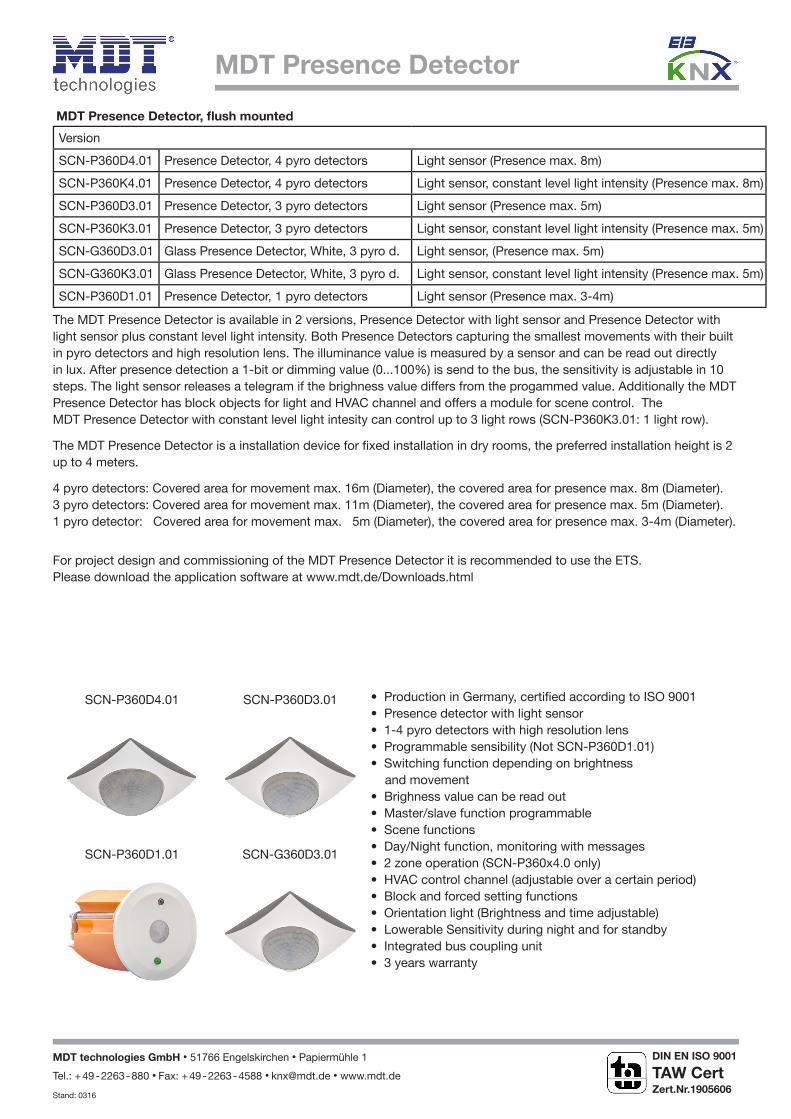
MDT Presence Detector, lush mounted
Version
SCN-P360D4.01 Presence Detector, 4 pyro detectors Light sensor (Presence max. 8m)
SCN-P360K4.01 Presence Detector, 4 pyro detectors Light sensor, constant level light intensity (Presence max. 8m)
SCN-P360D3.01 Presence Detector, 3 pyro detectors Light sensor (Presence max. 5m)
SCN-P360K3.01 Presence Detector, 3 pyro detectors Light sensor, constant level light intensity (Presence max. 5m)
SCN-G360D3.01 Glass Presence Detector, White, 3 pyro d. Light sensor, (Presence max. 5m)
SCN-G360K3.01 Glass Presence Detector, White, 3 pyro d. Light sensor, constant level light intensity (Presence max. 5m)
SCN-P360D1.01 Presence Detector, 1 pyro detectors Light sensor (Presence max. 3-4m)
The MDT Presence Detector is available in 2 versions, Presence Detector with light sensor and Presence Detector with
light sensor plus constant level light intensity. Both Presence Detectors capturing the smallest movements with their built
in pyro detectors and high resolution lens. The illuminance value is measured by a sensor and can be read out directly
in lux. After presence detection a 1-bit or dimming value (0...100%) is send to the bus, the sensitivity is adjustable in 10
steps. The light sensor releases a telegram if the brighness value differs from the progammed value. Additionally the MDT
Presence Detector has block objects for light and HVAC channel and offers a module for scene control. The
MDT Presence Detector with constant level light intesity can control up to 3 light rows (SCN-P360K3.01: 1 light row).
The MDT Presence Detector is a installation device for ixed installation in dry rooms, the preferred installation height is 2 up to 4 meters.
4 pyro detectors: Covered area for movement max. 16m (Diameter), the covered area for presence max. 8m (Diameter).
3 pyro detectors: Covered area for movement max. 11m (Diameter), the covered area for presence max. 5m (Diameter).
1 pyro detector: Covered area for movement max. 5m (Diameter), the covered area for presence max. 3-4m (Diameter).
For project design and commissioning of the MDT Presence Detector it is recommended to use the ETS.
Please download the application software at www.mdt.de/Downloads.html
• Production in Germany, certiied according to ISO 9001• Presence detector with light sensor • 1-4 pyro detectors with high resolution lens• Programmable sensibility (Not SCN-P360D1.01)
• Switching function depending on brightness
and movement
• Brighness value can be read out• Master/slave function programmable• Scene functions• Day/Night function, monitoring with messages• 2 zone operation (SCN-P360x4.0 only)
• HVAC control channel (adjustable over a certain period)• Block and forced setting functions• Orientation light (Brightness and time adjustable) • Lowerable Sensitivity during night and for standby • Integrated bus coupling unit • 3 years warranty
SCN-P360D1.01 SCN-G360D3.01
MDT technologies GmbH • 51766 Engelskirchen • Papiermühle 1
Tel.: + 49 - 2263 - 880 • Fax: + 49 - 2263 - 4588 • [email protected] • www.mdt.de
Stand: 0316
DIN EN ISO 9001
TAW Cert
Zert.Nr.1905606
N

MDT Presence Detector
Technical DataSCN-P360D4.01
SCN-P360K4.01
SCN-P360D3.01
SCN-P360K3.01
SCN-G360D3.01
SCN-G360K3.01SCN-P360D1.01
Covered area (Diameter)
Movement * 16m 11m 11m 5m
Presence * 8m 5m 5m 3-4m
Sensitivity adjustable in 10 steps adjustable in 10 steps adjustable in 10 steps ixed, not adjustable
Angular coverage 360° 360° 360° 360°
Range of light sensor 5 - 1000 Lux 5 - 1000 Lux 5 - 1000 Lux 5 - 1000 Lux
Speciication KNX interface TP-256 TP-256 TP-256 TP-256
Available application software ETS 3/4/5 ETS 3/4/5 ETS 3/4/5 ETS 3/4/5
Permitted wire gauge
KNX busconnection terminal 0,8mm Ø, solid core 0,8mm Ø, solid core 0,8mm Ø, solid core 0,8mm Ø, solid core
Power supply KNX bus KNX bus KNX bus KNX bus
Power consumption KNX bus typ. <0,3W <0,3W <0,3W <0,3W
Operation temperature range 0 to + 40°C 0 to + 40°C 0 to + 40°C 0 to + 40°C
Enclosure IP 20 IP 20 IP 20 IP 20
Dimensions (W x H x D) 85mm x 85mm x 38mm 75mm x 75mm x 35mm 92mm x 92mm x 32mm 43mm x 43mm x 30mm
Examplary circuit diagram SCN-x360xx.01
Covered area SCN-P360x4.01 Covered area SCN-x360x3.01
Covered area SCN-P360x1.01
* at maximum mounting height of 4m (See images below).
MDT technologies GmbH • 51766 Engelskirchen • Papiermühle 1
Tel.: + 49 - 2263 - 880 • Fax: + 49 - 2263 - 4588 • [email protected] • www.mdt.de
Stand: 0316
DIN EN ISO 9001
TAW Cert
Zert.Nr.1905606
N


