0 OWNER'S MANUAL - Beaver Ambassador...
50
p ) i^t jrit tfb r ) )d§ r ) PUPS' 0 P^§ P?SP «_A •______ l# I^P PIP ^w E_A P5P w_p M (__f_ ip) HP g___. .SF HP IP OWNER'S MANUAL Magnum S-Series Magnum M-Series Magnum B-Series -:£*-*» |P IP IP W Magnum Manufacturing 425 N. Third Street Harrisburg, OR 97446 Warranty: 800-344-6332
Transcript of 0 OWNER'S MANUAL - Beaver Ambassador...

p )
i^t
jrit tfb r ) )d§ r ) PUPS'
0 P^§
P?SP
«_A
•______
l #
I P
PIP
^ w
E_A
P5P
w_p
M (__f_
ip)
HP g___.
.SF
HP
IP
OWNER'S MANUAL Magnum S-Series Magnum M-Series Magnum B-Series
-:£*-*»
|P IP IP W
Magnum Manufacturing 425 N. Third Street Harrisburg, OR 97446 Warranty: 800-344-6332

Revision Date: 7 - 20 - 97

The descriptions and specifications in this manual were in effect at the time of its approval for printing. The manufacturer reserves the right to change specifications or designs without notice or incurring obligation. This manual includes information on several different models. Your motorhome may not contain every system described.

Table of Contents
Section 1 - Becoming Familiar with Your Chassis Warranty Information Breaking in Your New Chassis Fueling Transmission Cruise Control Steering System Brakes Exhaust System Gauges Indicator Lights Towing
Section 2 - Operating the Vehicle Starting the Engine Fuel Economy Climbing and Descending Grades Cold Weather Starting and Operation Driving in Dangerous Conditions
Section 3 - Chassis Maintenance Maintenance Intervals Maintenance Instructions
Fluid Capacities and Specifications Filter and Belt Specifications Chassis Service Center Tire Charts Lubrication Points
S-Series "Blue Streak" with Ellipti-Ride S-Series "Blue Streak" with Rayco Air M-Series "Blue Max" B-Series
Rnvinp. Does Not Start Troubleshooting
1 1 2 3 4 7 8
10 13 14 17 19
21
21 23 24 25 25
27 27 29
A-l A-2 A-3 A-4
A-5 A-6 A-7 A-8 A-9

(PUP
p w
p )
p )
Ft
Ml
P§_l
MB i__i___k P ^
5 Becoming Familiar With Your Chassis — — - — - — - - - — — - — - — - - — — ^ ^ ~ — — — — - - • — — — - — — , ~ _ ~ _ _ . m „ „ , . , _ — „ ,
P» Section 1 fVmr
i i i e__l»
p Before Driving
!• Before leaving on your first trip with your new vehicle, take the time to familiarize yourself with your chassis and it's components. Read through the owner's manuals pertaining to your chassis, and allow time to look the chassis over in order to locate the various
0 chassis components and service points. Refer to the section in this P manual on daily maintenance checks for your chassis, and perform P the daily maintenance; getting into the habit of performing routine Q maintenance on your vehicle will help to ensure trouble-free ^ operation of your Magnum chassis. Look at your Vehicle Owner's 0 Manual as well, as it may also contain additional items to check p before driving.
i» About Your Warranty Hi
k Magnum Manufacturing, Inc. stands behind it's products with a p 3 year/36,000 mile warranty. Enclosed in your owner's packet is a _____ ii Uj. \W
i___ P _____ W w

complete explanation of your Magnum warranty, including coverage and limitations, as well as how to receive warranty service. _ Following is a partial list of items which Magnum Manufacturing cannot be responsible for under warranty due to circumstances and conditions outside of our control:
1 Front-end alignments - your vehicle is aligned to strict standards at the factory, but it is recommended that you have your vehicle aligned after loading. The alignment of the front-end will change with different vehicle weights. Due to driving conditions, road hazards and normal wear, we cannot be responsible for any front-end alignments after the vehicle has left the factory.
2 Tire Balance - due to driving conditions and road hazards, ' we cannot be responsible for the balance ofthe tires.
3. Routine maintenance checks and services as listed in this
manual.
4. Component or system failure due to abuse, overloading, or
neglect.
5 Any alterations or components added to the chassis, or problems related to or caused by such alterations or components after the chassis has left the factory.
ntrol. 6. Any other damage or failure which is beyond our co
Breaking In Your New Chassis
During the first 1,000 miles of driving your new vehicle, the chassis components go through an adjustment or b r e a ^ i ^ o d P a y special attention to your vehicle and driving habits during tins Ume^ period. Look over the following recommendations and keep them in mind during the break-in period:

w IP
ft
H
_n__ w 9 9 p IP p p IP p p p p p p p p p p
1. Try not to drive continuously at the same speed; components tend to adjust better if driving speeds are varied during the first 1000 miles.
2. Apply the brakes gradually to slow down and avoid repeated heavy stops.
3. Do not add oil additives to the engine or other systems during the first few thousand miles of operation; additives may prevent components from breaking in properly.
Fueling Your Vehicle
w
i__k
& • s
9 WARNING Fuel is highly flammable. Do not refuel while smoking or near open flame or sparks. Always stop the engine when fueling and fill the tank outdoors. Remove the fill cap with caution, as internal pressure may cause fuel expulsion.
IP
In order to ensure easy starts and overall performance, always use clean, good quality fuel in your chassis. Recommended fuels for use in the Caterpillar Diesel Truck Engines are No.2-D diesel fuel and No.2 fuel oil with a minimum cetane of 40. When operating the vehicle at higher altitudes or low temperatures, use a fuel with a higher cetane number. Refer to the Caterpillar Operation & Maintenance Manual for more specific fuel recommendations.
Water, dirt, and other contaminants may be introduced into the fuel system while fueling your vehicle. These contaminants can cause damage to the entire engine; always follow the maintenance guidelines in this manual for servicing the fuel filter/water separator to prevent engine damage. Always keep your fuel tank full, especially when storing the vehicle or not driving it for longer than a week; this will help prevent condensation in the fuel tank and the introduction of water in the fuel system.

About Your Vehicle £
Transmission #•"
Read the Transmission Operator's Manual for more detailed information on description, operation, and maintenance of your transmission.
The Allison MD transmission is a six-speed automatic transmission controlled by an Electronic Control Unit (ECU) located at the driver's side console. The ECU is commonly referred to as the "shifter". This unit processes information from the transmission and engine, and controls the shifting ofthe transmission accordingly. It also monitors the transmission systems for problems that may occur with the system, and has the ability to limit operation ofthe transmission in certain cases to avoid transmission damage.
The World Transmission is also capable of adapting to your particular driving style. As the vehicle is operated, the ECU measures and stores each shift, and uses the information to find an optimum shift point. With a new or recalibrated ECU, it may be necessary for it to adapt or "learn" all over again. This will result in apparently abnormal shifts for a short time. Simply drive the vehicle as you normally would, and in time it will re-adapt to proper shift quality.
The ECU is equipped with a push button selector for selecting driving ranges. Each switch pad is labeled according to it's function:
NEUTRAL (N) - Use this selection for starting the engine, checking vehicle accessories, and idling. The ECU should automatically select neutral when the ignition key is turned on, and should not allow the engine to start in any gear selection other than neutral. Seek service immediately if these conditions are not met. Always place the transmission in neutral before turning off the engine.

^ WARNING ^ ALWAYS set the parking brake when the transmission is in neutral. NEVER leave the vehicle unattended with the engine running or the parking brake off; sudden vehicle movement may occur resulting in property damage or injury. NEVER coast the vehicle with the transmission in neutral; this may result in transmission damage and loss of available engine braking.
REVERSE (R) - To shift into reverse, the vehicle must be completely stopped; the transmission will not shift otherwise. Locate and press the "R" pad on the shift selector. The transmission will engage and the display will register "R".
DRIVE (D) - To shift into drive, locate and press the "D" pad on the shift selector. The transmission will automatically upshift as the vehicle speed increases, and downshift as the vehicle speed decreases. The "select" indicator on the shift selector will display the highest gear available, and the "monitor" indicator will display the gear being used.
SELECTING GEARS (ft,£) - The arrow pads on the shift selector can be used to select different gears to meet driving conditions. Press the down arrow pad on the shift selector to shift to a lower gear, and the up arrow pad to select a higher gear. When using the arrow pads to select different gear ranges, the select indicator will show the highest gear that the transmission will shift to. The transmission may, however, shift to a higher gear if damage to the engine or transmission is possible due to engine overspeed, regardless ofthe gear selector setting.
MODE (MODE) - The mode button on the shift selector can be used to change the shift patterns in order to enhance the fuel economy ofthe vehicle. With the mode off, the transmission shifts are delayed until a higher engine RPM is attained, resulting in improvement in overall performance. By turning the mode on, the transmission will shift into the next higher

gear sooner, allowing for smoother shifts and improved fuel economy. The mode can be turned on or off at any vehicle speed in order to meet driving conditions.
In case of transmission service problems, the ECU will automatically log a diagnostic code in it's memory, and may restrict shifting in order to prevent damage to the transmission, vehicle or other chassis components. In case of a problem which may result in damage, the "DO NOT SHIFT" light on the shift selector may illuminate The "DO NOT SHIFT" light should illuminate for a few seconds during engine start up to show that the light circuit is operating properly; if it does not, request service immediately.
Illumination ofthe "DO NOT SHIFT" light, accompanied by eight seconds of short beeps, indicates that the transmission has logged a service problem which may cause damage to components. The transmission will automatically limit shifting of the transmission, but may be operated in order to seek service as long as shift parameters set by the ECU are met.
If the service problem is temporary, it may be possible to reset the system using the arrow pads on the shift selector and following these procedures:
1. Park the vehicle in a safe location with the parking brake on.
2. Simultaneously press both arrow pads on the shift selector
one time.
3. Press and hold the "MODE" button until a tone is heard. Release the "MODE" button.
After following these steps, the transmission will operate normally ifjhe^erymMohlmymJmmmL If the service Iiuunaiijr j —- n T T n T CTirpT"' ^ o h t Will COlTie problem was not temporary, the DO NO 1 bmr i _ ng" back on, and shifts may once again be limited. In either case, the transmission should be checked at the earliest opportunity.

Cruise Control
* WARNING % NEVER use the cruise control on slippery driving surfaces or in congested traffic; doing so will lead to loss of control ofthe vehicle and impaired reaction time to obstacles. NEVER shift the transmission into neutral when using the cruise control; doing so will cause the engine to overspeed and may cause damage to the vehicle.
The cruise control allows you to set and maintain the speed of your vehicle when the vehicle speed is above 25 mph. The cruise control will not work while the brake pedal is depressed, or if the exhaust brake switch is on. Using the cruise control switches, you are also able to set the idle speed ofthe engine above the governed idle speed. To disengage the cruise control or controlled fast idle, turn the on/off switch to the off position, press on the brake pedal, or turn the exhaust brake switch on. The cruise control switches are located on the driver's side console to the left ofthe driver's seat.
ON/OFF SWITCH - This switch must be in the "ON" position to engage the cruise control or controlled fast idle. Shutting off this switch with the cruise control or the controlled fast idle engaged will cancel them.
SET/DECEL SWITCH - Use this switch to engage the cruise control and controlled fast idle. The set function ofthe switch will set the cruise control at the desired vehicle speed. As soon as you reach the vehicle speed you wish to travel at, momentarily engage and release the switch, and the current vehicle speed will be maintained. Engaging the switch while the cruise control is set will slow the vehicle speed. Engage the switch until the vehicle slows to the desired speed, and release. Momentarily engaging the switch will decrease the vehicle speed by one mph.

Use the controlled fast idle function to set the engine rpm at a desired rpm above that ofthe governed idle speed while the vehicle is parked. Depress the throttle until the desired engine speed is reached, and engage and release the set/decel switch This will hold the engine speed selected until the on/off switch is turned off, or the brake is depressed. Engaging the switch while the controlled fast idle is set will decrease the engine speed.
RESUME/ACCEL SWITCH - Use this switch to return to a previously set vehicle speed after the cruise has been canceled by depressing the brake pedal, engaging the exhaust brake, or turning the on/off switch to the "OFF" position. After the vehicle has slowed to avoid obstacles and the roadway is clear, momentarily engage and release the switch, and the vehicle will return to the previous set speed. While the cruise control is engaged, depressing this switch will increase the set speed of the vehicle. Momentarily engaging the switch will increase vehicle speed by one mph.
While in the controlled fast idle mode, the use of this switch
will increase the idle speed.
FAST IDLE - Depending on the model of your vehicle, it may be equipped with a fast idle button. Pressing and releasing this button will automatically increase the idle speed ofthe engine to 1 000 rpm, allowing for faster warm up times. To return to normal idle speed, press and release the fast idle button again or depress the brake pedal. The fast idle function will not work if the exhaust brake switch is on.
The Steering System
The power steering system uses hydraulic power from the engine to provide full-time hydraulic steering, instant response, and the ability to help absorb road shock. In case of a loss of hydraulic

power, the system is designed to provide mechanical back-up steering in order to steer the vehicle off the road to safety.
Power Steering Checks
While driving your vehicle, be aware of any changes in the feel of your steering system, and have the system checked if you notice any apparent differences in the system. It is normal to hear a hissing sound in full left and right turns.
^ WARNING ^ NEVER hold the steering wheel at the extreme right or left for more than five seconds. Doing so may cause damage to the steering system components.
Have the steering system checked for damage after a severe impact such as striking large potholes or curbs, and front-end collisions. Observe the alignment ofthe steering wheel spokes; a change in the alignment may indicate damage to the steering components or suspension.
Front-End Alignment
Due to driving conditions and road hazards, we cannot be responsible for alignments after the vehicle has left our factory. Your vehicle has been aligned to very strict standards while at the factory. The alignment will change, however, once the vehicle is fully loaded. It is recommended that a front-end alignment be performed on your vehicle after you have taken possession and loaded your vehicle.
Adjusting the Steering Column
Your steering column has both tilt and telescope functions to adjust the steering wheel for a comfortable driving position. To adjust
the tilt ofthe column, pull the lowest lever on the left hand side ofthe column toward you. The column can then be moved to the desired position; releasing the lever will lock the column into place. You can use the column tilt for convenient entry and exit ofthe captain's chair.
To telescope the steering column, push the same lever away from you, and extend or retract the column by pushing the steering wheel down or pulling it towards you to the desired position. Release the lever to lock the column into place.
The Brake System
Your brakes are an important safety feature of your vehicle. Improperly maintained and defective brakes can lead to property damage, injury, and loss of life. Always follow the maintenance schedule to ensure proper maintenance ofthe brake system, and observe any changes in braking action that may indicate a problem with the brakes. Increased brake pedal travel, pulling to one side while braking, and strange sounds while braking may indicate a problem with the service brakes. If you notice any of these or any other unusual conditions with the brake system, investigate the problem immediately and have the system inspected by a service center if necessary.
Using the Park Brake «H
To set the park brake, place the transmission in neutral, and depress the service brake pedal. Pull out on the park brake control until it stops, and release the service brake.
To release the park brake, first ensure that the transmission is in neutral. Depress the service brake pedal and push the park brake control in fully.
10

WARNING ^ ALWAYS set the park brake when parking the vehicle. Do not use the transmission in place ofthe park brake as it has no braking effect on the vehicle. NEVER release the park brake with the vehicle in gear; sudden vehicle movement may occur resulting in property damage and/or injury.
Always make sure that the park brake is released prior to driving the vehicle, and check the park brake warning light. Driving the vehicle with the park brake on will result in reduced brake effectiveness and excessive brake wear.
The Service Brakes
Magnum chassis are either equipped with a hydraulic-over-hydraulic brake system or an air-over-hydraulic brake system. It will only have an air-over-hydraulic system if it is equipped with the Magnum Air™ suspension system.
If your brakes appear to make the vehicle pull to one side while stopping during the first 500 miles, check the tire pressures on each side ofthe vehicle to ensure that they are even. If the tire pressures are even, make ten moderately fast stops from 40 mph. Repeat if required. This procedure may be necessary to properly seat the brake pads against the rotors. If the brakes pull after the first 500 miles, have them serviced immediately.
WARNING ^ NEVER drive the vehicle with your foot resting on the brake pedal. Doing so may result in abnormally high brake pressure, excessive brake wear, and increased stopping distances.
11

Hydraulic-Over-Hydraulic Brakes
Your brake system utilizes a hydraulically powered booster which eases the effort needed to apply the brakes, and reduces the pedal travel needed for braking as compared to a non-powered system Under normal conditions, the powered booster utilizes hydraulic pressure from the power steering pump to provide power assist to the brake system. In the event of a loss of hydraulic pressure, the powered booster has an electrically powered reserve pump to create hydraulic pressure so that the vehicle can be stopped safely.
The reserve hydraulic pump can be tested by stepping on the brake pedal while the ignition switch is in the "OFF" position. You should be able to hear the pump, as well as an alarm sounding and dash light warning while depressing the brake pedal. If this ever occurs while the engine is running, it may indicate a main hydraulic system malfunction, and you should seek service.
Air-Over-Hydraulic Brakes
The air-over-hydraulic brake system utilizes compressed air from a compressor on the engine to assist braking effort. When the brake pedal is depressed, air pressure is applied to two pressure converters, where the air pressure is converted to hydraulic pressure in the brake lines, which will engage the brake calipers at each wheel.
The Exhaust Brake
The exhaust brake increases exhaust pressure in the engine in order to use the engine to help slow the vehicle. It is designed to increase braking efficiency while saving the service brakes from overuse The exhaust brake will not engage unless the throttle is at idle position. The exhaust brake works best when the engine is at higher rpm's, and is very effective for slowing the vehicle while going downhill and for slowing the vehicle for turns and stops. While
12

the exhaust brake is engaged, the transmission automatically downshifts at a higher rpm in order to increase the brake's effectiveness.
x WARNING % DO NOT use the exhaust brake when road surfaces are slippery; loss of vehicle control can result. NEVER Rely on the exhaust brake to bring the vehicle to a complete stop; it is not intended to be used for this purpose.
To use the exhaust brake, let the throttle return to the idle position, and press the exhaust brake lever switch on the driver's side console. To disengage the exhaust brake, either depress the throttle, or turn the switch off.
The Exhaust System
9 WARNING 8 NEVER run the engine in enclosed areas and avoid sitting in a parked or stopped vehicle for any extended amount of time with the engine running. Exhaust gases which contain Carbon Monoxide may build-up and can be harmful or potentially lethal. Carbon Monoxide is both colorless and odorless and is not easily detectable. Carbon Monoxide can be present with all other exhaust gases. If you smell exhaust fumes of any kind inside your vehicle, have it inspected immediately by a service center and have the condition corrected. DO NOT drive the vehicle or occupy it for any length of time with exhaust fumes present.
For protection from possible entry of carbon monoxide into your vehicle, have a technician inspect the exhaust system and body ventilation system:
1. Whenever the vehicle is raised;
13

2. Whenever you notice a change in sounds from the exhaust
system;
3. Whenever the vehicle has impacted another vehicle, object, or road obstruction.
While idling the engine in an open area, be sure to properly ventilate the interior ofthe vehicle to help avoid the danger of exhaust fiimes. To ventilate the vehicle, open the windows at least one inch, and adjust the heating or air conditioning to draw outside air into the vehicle as follows:
1. If the vehicle has outside air vents, open them fully.
2 Heating - Set the fan speed on medium or high, with the controls on heat or defrost, and the temperature control on any desired position.
3. Air Conditioning - Set the fan speed on medium or high with the controls on any position except off or max. The temperature control should be at mid-position.
Gauges
Depending on the model of your vehicle, it may or may not have all ofthe following gauges:
WATER COOLANT TEMPERATURE GAUGE - The _ water temperature gauge shows the temperature ofthe engine coolant. Normal temperatures for the water coolant as indicated by the gauge will range between 190 and 215 degrees Fahrenheit, depending on outside air temperatures and engine load The temperature may exceed this range under hot weather and heavy loads. The maximum allowable temperature for the system is 230 degrees Fahrenheit.
14
HIGH COOLANT TEMPERATURE INDICATOR - Your vehicle is equipped with a high temperature indicator light which activates when the engine coolant temperature begins to reach it's higher limits. If the light activates, it is signaling that the engine is not cooling adequately for the conditions it is being applied to. If the high coolant temperature indicator activates, reduce the engine load or pull to the side ofthe road to allow the engine to cool before continuing; allowing the engine coolant temperature to continue to climb may result in engine damage. Your vehicle engine electronics should begin to cut power to the vehicle at 222 degrees Fahrenheit in order to prevent overheating ofthe engine; if the temperature ofthe coolant continues to climb, available engine power will continue to decline until the temperature reaches 230 degrees Fahrenheit, at which point the engine will overheat.
FUEL GAUGE - The fuel gauge displays the approximate amount of fuel that is in the fuel tank. When checking the fuel level, the ignition key must be in the "ON" position, and the vehicle must be on smooth, level ground in order to obtain an accurate reading. While the vehicle is in motion, it is normal for the fuel gauge needle to move due to the movement of fuel in the tank.
TACHOMETER - The tachometer indicates the approximate number of engine revolutions per minute (rpm). Use the tachometer while driving to ensure optimum shift points and to prevent the engine from lugging or overrevving. The engine can be allowed to operate at a high idle without damage for short periods of time, but should not be allowed to go over 2900 rpm at any time. Allowing the engine to operate over 2900 rpm can result in serious damage to the engine.
TRANSMISSION TEMPERATURE GAUGE - The transmission temperature gauge indicates the temperature of the transmission fluid. The normal operating range is between 140 and 290 degrees Fahrenheit. Under cool conditions it is normal for the temperature to stay below 140 degrees. If the
15

transmission temperature exceeds 290 degrees, it may be necessary to reduce the engine load to allow the transmission to cool before continuing.
ENGINE OIL PRESSURE GAUGE - The engine oil pressure gauge indicates the relative oil pressure. While the engine is running at rated speed with SAE 15W40 oil, and at operating temperature, the normal oil pressure should be between 35 and 70 psi. During idling it is normal for the oil pressure to be lower, and a higher pressure is common with a cold engine at start-up. If the oil pressure does not register during start-up or operation, pull to the side ofthe road and shut down the engine immediately; check the engine oil level and seek service if necessary. Operating the engine with no oil pressure will result in severe engine damage.
ENGINE OIL GAUGE LIGHT - If the engine oil pressure ^ drops below a safe operating level, an indicator light in the oil pressure gauge will illuminate. In the event the light comes on, pull the vehicle to a safe location, check the engine oil level, and act accordingly.
BATTERY VOLTAGE GAUGE - The battery voltage gauge indicates the amount of voltage that the batteries are receiving from the alternator. Normal voltage to the batteries with no load on the batteries will be between 13 and 14.5 volts with the engine running. The voltage reading will be lower if the batteries are subjected to a load.
SPEEDOMETER AND ODOMETER - The speedometer indicates the speed ofthe vehicle in miles per hour or kilometers per hour. The odometer records the total distance the vehicle has traveled.
TURBO BOOST GAUGE - The turbo boost gauge indicates, in pounds per square inch, the pressure ofthe intake air after it has been pressurized by the turbocharger. Normal readings for
16

this gauge range between 0 and 28 psi, depending on the conditions that the engine and vehicle are being subjected to.
AIR PRESSURE GAUGE - Indicates the air pressure in pounds per square inch at which the air system is operating on vehicles equipped with air suspension and/or brakes.
Indicator Lights
Depending on the model of your vehicle, it may or may not have all ofthe following indicator lights. The indicator lights are located at the top ofthe dash gauge panel.
HIGH BEAM INDICATOR - The high beam indicator lets you know if your headlights are on high beam when the headlights are on. The indicator will illuminate when the high beams are on.
HAZARD WARNING LIGHTS - The hazard light system serves as a warning to other motorists to use extreme caution when approaching or passing your vehicle. To turn on the hazard light system, pull the switch located on the bottom of the steering column. Push the switch in to turn the lights off Turning the hazard light system on causes the turn signal lights and indicators to flash on and off continuously.
PARK BRAKE INDICATOR LIGHT - The park brake indicator light illuminates when the park brake is on. Do not drive the vehicle with the park brake on, as brake damage may result.
BRAKE SERVICE INDICATOR LIGHT - In case of a loss of main hydraulic pressure, the brake service light will illuminate and a warning buzzer will sound. In the event this happens, seek a repair facility in order to correct the problem.
17
ii0^^^i&^^ywm0MMM$$Mm.

18
FAST IDLE INDICATOR - The fast idle indicator light will illuminate when the fast idle has been enabled.
CHECK ENGINE INDICATOR - The check engine indicator light illuminates when the engine monitoring system detects a problem with the engine. The light also illuminates during engine start-up to check ofthe circuit. If, while operating the vehicle, the check engine light illuminates, refer to the Engine Diagnostics section ofthe Caterpillar Operation & Maintenance Manual for evaluation and corrective measures.
INLET AIR HEATER LIGHT - The inlet air heater light illuminates when the inlet air heater is active. Do not start the vehicle when the air inlet activates prior to start-up with the key on. The light will illuminate from 2 to 30 seconds depending on coolant and intake air temperatures. After the light cycles off, start the engine. The inlet air heater light may cycle on and off or remain on for as long as 13 minutes depending on engine and air temperatures until the engine warms up.
LEFT AND RIGHT TURN SIGNALS - To signal for a left turn, pull the turn lever down until it stays in the down position. To signal a right turn, push the turn signal lever up until it stays in the up position. If the indicator continues to flash after making a turn, manually return the lever to the center position. Be sure to use the signals when turning corners and changing lanes. If the direction indicator light in the instrument panel does not flash when you signal a turn, the signal system is malfunctioning. Have the condition corrected as soon as possible and use accepted hand signals in the meantime.
LIGHTS - The control knob for the headlights, tail-lights, parking lights, license plate lights, marker lights, and instrument panel lights is located on the driver's side console. Following is a list of switch positions and light functions:
1. When the switch is pushed fully in, all lights are off.
2. With the switch pulled out to the first stop, all lights are turned on with the exception ofthe headlights.
3. With the switch pulled out fully, all lights should be on.
4. To adjust the panel light brightness, rotate the light control knob.
5. To switch the headlight brightness pull the turn signal lever towards you.
Towing a Trailer or Vehicle
Towing puts extra strain on your vehicle's engine, drive train, brakes, tires, and suspension. With this and the safety of yourself and others in mind, be sure to match the towed load to the vehicle as follows:
The Gross Combined Weight Rating (GCWR) and the actual loaded weight ofthe coach determine the towing capacity. Subtract the actual weight ofthe vehicle from the GCWR to determine the acceptable weight this vehicle can tow. If the GCWR is exceeded, serious damage to the drive train may result, and safety may be compromised. Do not exceed the rated hitch capacities of 5000 pounds towing weight and 500 pounds hitch weight when determining your towing capacity.
#- WARNING # -NEVER exceed the rated hitch capacities of your vehicle, or exceed the weight limits of your vehicle. Doing so may result in property damage and/or injury, and void any warranty claims resulting from overloading.
19

Make sure the towing equipment is properly and safely attached to your vehicle. Check to see that the tires are properly inflated and always use a safety chain to provide a backup for the hitch. The tongue weight ofthe trailer should be approximately 10 to 15 % ofthe loaded trailer weight for best handling. Heavy trailers (over 2000 lbs.) should have trailer brakes hooked up.
Adjust your driving habits to provide for the extra length ofthe trailer. When turning, drive slightly beyond the normal turning point before steering in that direction. Descend hills at a slower speed than usual, and avoid sudden braking.
IzzO
20

Operating the Vehicle
Section 2
Starting the Engine
When starting the engine, always follow these procedures:
1. Turn the headlights off. This will ensure that all available battery power will go to the starter.
2. Ensure that the park brake is engaged.
3. Turn the ignition switch to the "ON" position. Check to see that the transmission is in neutral.
4. Look at the dash warning lights; the "DO NOT SfflFT", "LOW OIL PRESSURE", and "PARK BRAKE" lights should come on and remain on. The "INLET AIR HEATER" and "CHECK ENGINE" lights should cycle on and then turn off. Wait until the "INLET AIR HEATER" light cycles off to prevent excessive white smoke during starting.
21
^^^^^^^l^^^^^^^^^^^^^^^^^^^^^^^^^^^p ^^^^^^^WHW^W^^^^M^yMWXPiz

NOTE: If any ofthe warning lights fail to come on, have the problem corrected. If the "CHECK ENGINE" light remains on or comes back on during the starting procedure, the engine ECM may have detected an engine systems fault. Refer to the engine diagnostics section ofthe Caterpillar Operation & Maintenance Manual for corrective action.
5. Without pushing or holding the throttle down, turn the ignition switch to the "START" position and crank the engine. The electronic controls on the engine will automatically deliver the correct amount of fuel to the engine for starting.
NOTE: To avoid starter damage, do not crank the engine for more than 30 seconds at one time. If the engine fails to start, wait one minute before attempting to start the engine again.
6. Release the ignition switch to the "ON" position immediately after the engine starts.
NOTE: Observe the oil pressure warning light and gauge to ensure that oil pressure is at an adequate level after starting. Oil pressure at start-up should be between 20 and 70 psi, depending on the engine temperature. Turn the engine off immediately if the oil pressure does not register within 15 seconds of engine start-up and take corrective measures.
7. If the engine is cold, it may automatically idle at an increased speed in order to warm the engine faster. Do not attempt to drive the vehicle if this occurs; wait until the engine idles down. As soon as the oil pressure and air pressure are at normal levels, the engine can be operated at light or moderate loads. Applying a light load will help the engine warm up faster. Do not operate the engine at a heavy load until the engine has warmed adequately. Avoid lengthy idle times of over ten minutes as this will cause carbon build-up in the engine and may dilute the engine oil with raw diesel.
22

8. Disengage the park brake before driving.
Fuel Economy
Many factors contribute to the amount of fuel consumed during driving. Driving styles, wind resistance, terrain, vehicle weight, and engine driven accessories are some ofthe factors which can affect the fuel economy. Use the following guidelines to help increase fuel efficiency:
1. When starting out, use smooth, easy starts by gradually increasing speed, rather than using excessive throttle and accelerating quickly.
2. While operating the vehicle, keep the engine at a low to mid rpm range of 1400 to 2000 rpms. Doing so will use less fuel than operating at higher rpms.
3. While driving in rolling hills, avoid downshifts when going uphill, and use the downhill grades for accelerating, rather than the throttle.
4. Avoid extended idling to allow the engine to warm; only wait long enough for normal oil pressure to register and the engine coolant temperature gauge to begin to climb.
5. Operate the transmission with the MODE function on whenever possible; this allows for earlier shifts and enhanced fuel economy.
6. Follow the maintenance schedule for your chassis; proper maintenance will lead to enhanced fuel economy, vehicle performance, and longevity.
23

Climbing Grades
When climbing long, steep grades, it will be necessary to pay close attention to your vehicle and it may be necessary to make adjustments to compensate for the extra load on the vehicle drivetrain. The engine may be allowed to operate down to 1440 rpm while climbing a grade for best performance. Pay attention to the tachometer and vehicle speed, and downshift the transmission if the vehicle begins losing speed.
Observe the engine coolant and transmission temperatures closely, especially with extremely high outside temperatures, to ensure that the engine and transmission are cooling effectively. If engine and transmission temperatures begin to climb rapidly, downshift the transmission in order to increase engine rpm. This will increase the engine and transmission cooling efficiency by speeding up the cooling fan and increasing coolant flow.
Descending Grades
When descending a long grade, use the transmission and exhaust brake to maintain a safe, slow speed. Do not rely on the service brakes themselves to slow the vehicle while descending long grades; while they are designed to take a lot of heat, over-use can cause them to over-heat and loss of brake effectiveness can result.
Before descending a grade, downshift the transmission to a lower gear and use the engine to slow the vehicle. If the vehicle continues to accelerate down the grade, or it is necessary to slow the vehicle more, engage the exhaust brake. Use light, steady application ofthe service brakes to slow the vehicle more if necessary.
4* WARNING S*
NEVER allow engine rpm to exceed 2900 rpm as engine damage can
result.
24

f^w
W B PUP
i> • Gold Weather Starting and" Operation y H f_z} Starting and operating your vehicle during cold weather P# necessitates extra care and consideration of your vehicle. Refer to the • Caterpillar Operation & Maintenance Manual and use the following to guidelines to help ensure safe, troublefree operation of your vehicle: IP H ^ 1. Always follow the recommended oil, fuel, and coolant H specifications as outlined in the Caterpillar Operation & e# Maintenance Manual. Proper oil viscosity and coolant • mixes will help ease engine starting and help avoid engine to damage. (i A 2. Check the air inlet and filter daily, or as necessary when H driving in snow conditions. to 3. Your vehicle batteries work overtime during the hours of
winter darkness; check and service the batteries frequently to help ensure troublefree starts.
PUP
p) 4. Allow the engine to idle until it warms sufficiently for to operation; utilize the fast idle to warm the engine faster. pup
H 5. Start out slowly with the vehicle to allow the transmission m and axle lubricants time to circulate and warm before 0 putting them under full load.
mm
rib
m Driving in Dangerous Conditions _A ^ When driving on slippery road surfaces such as in ice, snow, or ^ wet conditions, always decrease your speed and allow for extra jH stopping room. Avoid quick direction changes and pump the brakes • steadily and evenly when stopping. Do not downshift the to transmission at speeds above 20 mph, or use the cruise control on J slippery road surfaces. PP y_____ P# HP
25
sp

Avoid driving through standing water if at all possible, especially if the water is over one foot deep, or if you are uncertain of the water depth. Never drive through water that has a noticeable current. If it is unavoidable to drive through water, follow these precautions:
1. Drive slowly with the transmission in low gear.
2. Apply the brakes lightly to keep the brake pads in contact with the rotors. This helps prevent mud and sand from contaminating the brake pads.
3. After leaving the water, maintain light pressure on the brakes for a short distance in order to heat the brakes so that they will dry.
4. After ensuring that there is not a vehicle behind you, make a test stop with the brakes in order to check the service brake's effectiveness. If the brakes have not returned to normal, continue to dry and test them until they have regained their effectiveness.
5. At the earliest opportunity, have all lubricants and wheel bearings checked to ensure that they have not been contaminated with water and/or mud.
26

B
hi m 'to 'to
Chassis Maintenance
Section 3
Maintenance Intervals
Refer to the Allison transmission manual for transmission service intervals.
Refer to the Caterpillar maintenance manual for additional service checks and intervals.
Change the rear axle lubricant initially at 1,000 miles; lubricant change interval is every 100,000 miles thereafter. Clean magnetic fill and drain plugs of metallic particles; clean or replace the axle breather. Drain axle housing completely and refill with approved lubricant until level with the bottom ofthe fill hole. See the specification chart for approved lubricants.
Engine oil and filter change intervals: 250 hp engine-every 10,000 miles 300 hp engine-every 6,000 miles 330 hp engine-every 6,000 miles
27

1. Daily Maintenance Checks a. Water fuel Separator b. Coolant level c. Engine Oil Level d. Transmission Fluid level e. Brake fluid level fi Tire Checks g. Inspect chassis for leaks h. Drain air tanks (air suspension chassis only)
2. Weekly Maintenance Checks a. Hydraulic fluid level b. Check Air cleaner filter minder; replace filter as required c. Inspect drive belts for wear and tension d. Inspect fuel, hydraulic, air conditioning, and coolant hoses e. Check air intake system for damage f. Check front axle hub lubrication level g. Lubricate radius rod (Velvet-Ride suspension only) h. Batteries
3. Every 6000 miles or 6 months a. Torque wheel lug nuts b. Lubricate leaf spring suspension c. Lubricate front axle king pins d. Lubricate tie rods e. Lubricate drag link f Lubricate drive shaft u-joints and slip shaft g. Lubricate brake pedal arm (except B-Series chassis) h. Lubricate steering shaft u-joints i. Lubricate fan drive bearing j . Clean engine and radiator assembly of excess oil and dirt k. Replace secondary fuel filter 1. Check engine coolant quality m. Check rear axle lubricant level
4. Every 12,000 miles or 12 months a. Replace primary fuel filter
0*
28

b. Rotate tires c. Inspect brake system d. Lubricate caliper slides
5. Every 18,000 miles or 18 months a. Inspect engine fan and shroud for damage
Inspect exhaust system for damage Inspect park brake system for damage/function Inspect engine mounts and torque engine bolts Change power steering fluid
Every 48,000 miles or 2 years a. Service cooling system b. Inspect crankshaft vibration damper
Maintenance Instructions
Daily Maintenance Checks
Water/Fuel Separator - inspect the water/fuel separator for any evidence of water or contamination. If the water fuel separator appears to have water or other contaminants in it, drain the separator until only clear fuel is seen using the following instructions:
Raycor system - run engine until it reaches operating temperature; stop engine. Place a cup below filter assembly drain valve and open drain valve. Operate priming pump on top of filter assembly and pump liquid into the cup until there is only clear fuel visible in the separator. Close drain valve and run engine for two to three minutes at half throttle to remove any air in the fuel system.
Winn system - Inspect the "H2O" light on the Winn system control pad. If it is illuminated, the sensor has detected water in the system which requires purging.
29

To purge the system, ensure that the reusable reservoir is in place on the water discharge tube and press the H2O purge button. Water in the system will be pumped into the reservoir. Visually check the prefilter for any signs of water or other contamination daily, and clean the prefilter as it becomes necessary. Refer to the Winn operation pamphlet, for more detailed information.
Coolant level - check surge tank coolant level with the engine cool. The surge tank should be 1/2 to 3/4 full. When adding coolant, refer to the to the specification chart for proper mixture and additives.
% WARNING I DO NOT attempt to remove surge tank cap when the engine is
Engine oil level - park the vehicle on a level surface with the engine off. The oil level should be between the ADD and FULL marks ofthe dipstick. Do not overfill the engine. Refer to the Caterpillar operation and maintenance manual for the proper oil to add to the engine.
Transmission fluid level - park the vehicle on a level surface with the transmission temperature above 140 degrees. With the engine running and the transmission in neutral, simultaneously depress both the up and down arrows on the transmission shifter. The shifter display may count down to let the fluid level settle, and then the number of quarts of fluid that the transmission is off will be displayed ( HI 2 denotes that the level is 2 quarts high; LO 2 denotes the level is low 2 quarts; OK denotes that the level is correct). Refer to the specification chart for the proper fluid to use.
Brake reservoir fluid level - visually check the brake reservoir to ensure that it is full. The level should be 1/8" from the top of the reservoir. If necessary to add fluid, first clean the reservoir
30

cap before removing to avoid contaminating the fluid in the reservoir. Refer to the specification chart for recommended brake fluid. It is normal for the level to slowly lower as the brake pads wear. Any sudden fluid loss may indicate a brake leak or other malfunction with the braking system; have the system serviced immediately if this occurs.
Tire checks - check tire pressure with a tire pressure gauge. Refer to the tire charts for the proper inflation ofthe tires according to the weight ofthe vehicle. Inspect the tires for any foreign objects imbedded in the tread or sidewall, unusual tire wear, or other damage to the tire and wheel. If any unusual conditions exist, have it examined by a professional.
Inspect chassis for leaks - examine the ground underneath the front and rear ofthe vehicle for evidence of any fluid, oil or coolant leaks. Leaks resulting in a steady drip or puddling of fluids should be serviced as soon as possible to prevent damage to the chassis or other components. No corrective action is necessary for leaks which are "seeping" and do not form drops, but they should be inspected frequently to ensure that they do not intensify.
Drain air tanks - drain the air tanks using the valves at the service center in order to expel any water that has accumulated in the tanks. This will help prevent corrosion and other problems with the air system.
Weekly Maintenance Checks
Hydraulic fluid level - check fluid level with the engine off and park brake on. Maintain fluid level between the ADD and FULL marks on the reservoir. Refer to the specification chart for recommended fluids.
31

Air cleaner filter minder - visually check the air restriction gauge on the service center. If the yellow indicator enters the red area ofthe indicator, replace the air cleaner element.
Inspect drive belts - examine the drive belts for unusual wear or damage. Replace any belts which show wear or damage. Refer to the Caterpillar operation and Maintenance manual for instructions and specifications regarding proper drive belt tension.
Inspect chassis hoses - inspect all hoses, fittings and clamps for unusual wear or damage, leaks, and abrasions. Repair, replace, or protect components as needed.
Air intake system - visually inspect the air intake system for any loose clamps and connections, or worn components. Check to ensure that ducting is not rubbing or wearing on other components. Gaps, voids, and holes in the air intake system will result in premature engine wear due to contaminants being introduced into the engine.
Front axle lubrication level - if wheels are equipped with stainless steel wheel liners, remove the center hub cover from the front wheels, and visually check the fluid level ofthe hub. Maintain fluid level at the OIL LEVEL line. Refer to the specification chart for recommended fluids.
Batteries - clean any dirt or other contaminants from the batteries. Inspect the battery terminals for any signs of corrosion, and check all connections and cable ends for looseness or damage. Clean, replace or repair any components which show signs of corrosion or other damage. Tighten any loose connections. After servicing, protect terminals and connections with petroleum jelly to help prevent corrosion.
Lubricate radius rod (Velvet-Ride only) - lubricate until fresh grease is seen flowing from ends. See lubrication chart

for lubrication points and specification chart for recommended lubricants.
6000 Miles or 6 Months
Change engine oil and filter - refer to the Caterpillar operation and maintenance manual for instructions and oil recommendations concerning engine oil and filter change.
Torque wheel lug nuts - check wheel lug nut torque; lug nuts should be torqued to 475 lb-ft. It is recommended to have this procedure performed by professionals with the proper tools. Check wheel lug nut torque at 50 miles and 500 miles after a wheel is removed or lug nuts loosened for other reasons.
Lubricate leaf spring suspension pins - (if equipped) see applicable lubrication chart for lubrication points. Lubricate until new grease can be seen flowing from each side of spring or spring shackle. It may be necessary to lubricate with the axle suspended in order to obtain even grease distribution across the spring pin. Refer to specification chart for recommended lubricants.
Lubricate front axle king pins - lubricate until new grease can be seen flowing from shim pack area. See lubrication chart for lubrication points and specification chart for recommended lubricants.
Lubricate tie rod ends - lubricate until fresh grease is seen flowing from grease boots. See lubrication chart for lubrication points and specification chart for recommended lubricants.
Lubricate drag link - lubricate until fresh grease is seen flowing from grease boots. See lubrication chart for lubrication points and specification chart for recommended lubricants.

Lubricate driveshaft u-joints and slip shaft - lubricate u-joints until fresh grease can be seen flowing from all four bearing seals. Lubricate slip shaft until fresh grease can be seen flowing from the relief hole at the end ofthe plug by the u-joint. Cover the hole with a finger and continue to lubricate until fresh grease flows from the sleeve yoke seal. See the lubrication chart for lubrication points and specification chart for recommended lubricants.
Lubricate brake pedal arm - lubricate until fresh grease flows from pivot. See lubrication chart for lubrication points and specification chart for recommended lubricants.
Lubricate steering shaft u-joints - lubricate until fresh grease is seen flowing from all four bearing seals. Lubricate slip shaft until grease flows from slip shaft.
Lubricate the engine fan drive bearing - refer to the Caterpillar operation and maintenance manual for instruction and location.
Inspect the engine and radiator assembly - inspect for accumulated oil, grease, and debris. Steam clean any build-up to aid in the detection of leaks, decrease fire hazard, and promote efficient engine cooling.
Replace final fuel filter - this is located on the chassis service center. Refer to the Caterpillar operation and maintenance manual and the section on priming the fuel system in this book.
Check engine coolant quality - to ensure the proper mixture of coolant and inhibitors. Refer to the Caterpillar operation and maintenance manual for information on how to check the quality of your coolant.
Check rear axle lubricant level - the lubricant level should be maintained at the bottom ofthe fill plug hole. See the specification chart for recommended lubricants.
34

12,000 Miles or 12 Months
Replace primary fuel filter located on the chassis service center.
Racor system - loosen the vent valve and drain plug to drain the element and bowl. Remove the element and bowl from the filter head and separate the element and bowl. Clean the bowl and lubricate the new seals with clean fuel. Install the bowl and new element onto the filter head firmly by hand. With vent valve open, operate pump until fuel purges from vent. Close vent valve. Start engine and operate for two to three minutes at half throttle to remove any air from the fuel system while checking for leaks. Correct any leaks with engine off.
Winn system - disconnect power to filter assembly by removing the fuse. Unplug the waterproof connector for the water sensor wire on the filter and remove the Schrader valve cap. Disconnect the fuel discharge line at the bottom ofthe filter. Hold a suitable container under the filter and depress the Schrader valve to drain the fuel from the filter. Turn the filter counter-clockwise to remove it. Clean the filter head with clean fuel and replace the spud gasket after lubricating it with clean fuel. Install the new filter element by turning it clockwise until it is hand-tight. Re-connect the water sensor wire, discharge line, and re-install the fuse. Depress the Schrader valve and activate the pump by pressing and releasing the "Air Purge" button on the filter control panel. Release the Schrader valve when fuel begins to purge from the valve. While checking for leaks, start the engine and run it at half throttle for two to three minutes to remove any air from the fuel system. Correct any leaks as required with engine off Re-install the valve cap on the Schrader valve.
Rotate the tires - to help extend the life ofthe tire tread. Rotate the tires by installing the front tires in the inner dual position; the inner dual tires to the outer dual position; and the outer dual tires to the front.
35

Have the brake system inspected - by a professional for brake pad wear, leaks, rotor condition, and any unusual or extreme conditions. Service, repair or replace as required.
Lubricate the brake caliper slides - during inspection or service. Improper or lack of lubrication may cause the brake pads to drag on the rotors after the brake is released resulting in premature wear of brake components.
18,000 Miles or 18 Months
Inspect the engine cooling fan and shroud for damage and looseness - ensure that all fasteners and mounting hardware is tight, check for broken fan blades, voids in the engine shroud, and damage to the radiator core. Check the fan drive bearing for excessive play. Refer to the Caterpillar operation and maintenance manual for specifications on acceptable fan drive bearing play.
Visually inspect the entire exhaust system - inspect for damage and leaks. Look for large dents, holes, excessive corrosion, and looseness. The presence of black soot may indicate an exhaust leak. Have the system evaluated by a professional if any of these conditions exist.
Visually inspect the park brake system - inspect for loose fasteners and worn components. To perform a function check ofthe park brake, park the vehicle on a level surface with no obstructions within 50 feet ofthe front ofthe vehicle. Check to ensure that nobody is in front or underneath the vehicle in case of sudden movement ofthe vehicle. Abort the procedure and stop the vehicle if at any time the vehicle begins to move. Do not exceed 1,200 RPM during this test as damage to the park brake system and sudden vehicle movement could result. With the park brake set, and foot on the service brake, place the transmission into drive. Slowly release the service brake; While watching the tachometer, gradually depress the accelerator until

i t i t PIP
| | the tachometer reaches 1,200 RPM. Release the accelerator at n this point, and place the transmission in neutral. If the vehicle |% moved during the test, have the park brake system serviced or P repaired as soon as possible. m
Inspect the engine mounts - inspect for damage and looseness. Check the torque ofthe engine mounting bolts.
Change the power steering fluid - drain the reservoir completely, and refill with approved fluid. See the specification chart for recommended fluids.
48,000 Miles or 2 Years
Service the cooling system - see the Caterpillar operation and maintenance manual for servicing guidelines and information.
Inspect the crankshaft vibration damper - refer to the Caterpillar operation and maintenance manual for proper procedures.
37

Capacities Engine Crankcase
Engine Coolant Capacity Rear Axle - Eaton 19060S, Blue Streak
Rockwell RSI9145, allother
Transmission @ oil change
with filter 33 quarts without filter 32 quarts
7.5 gallons 28 pints 33 pints 19 quarts
Lubrication and Fluid Specifications Fuel*
Engine Coolant*
Engine Oil*
Transmission Fluid" Brake Fluid Hydraulic Fluid Front Axle Hub Lubricant Chassis Grease
Rear Axle Lubricant
Brake Caliper Rails
No. 2-D diesel fuel and No.2 fuel oil. No. 1 fuel oil is acceptable for cold weather operation. Mixture of 50% antifreeze meeting ASTM D4985-89 requirements and 50% distilled or de-ionized water. Supplemental coolant additive to maintain 3 to 6% concentration. SAE 15W40 oil meeting API specifications CG-4, CG-4/SH, CF-4, CF-4/SF, or CF-4/SG. Operation below +5 degrees F may require different viscosity. Dexron II or Dexron HE fluids. DOT 3 Brake fluid only. Dexron II fluid. EP-SAE 90 gear oil or equivalent. Multi-purpose grease containing 3 to 5% molybdenum. SAE 85W-140 gear oil which meets or exceeds MIL-L-2105D. Silicone lube grease.
Refer to the Caterpillar Operation and Maintenance Manual for more information.
Refer to the Allison Transmission Operator's Manual for more information.
A-l

CHASSIS FILTERS AND BELTS
E N G l M O i r F i r r E R ^ ^ ^ ^
TRANSMISSfONTllTfER^^
ENGINE AIR CLEANER
MAIN DRIVE BELT
WATER PUMP BELT
PRIMARY FUEL FILTER:
RACOR
WINN
SECONDARY FUEL FILTER
AIR DRYER ELEMENT (PATR
CATERPILLAR 1R0739 ALLISON 29506377 FARR 998-42-009
CATERPILLAR 720244
RACOR R90T RACOR 200200 CATERPILLAR 1R0759
IOT ONLY)
NAPA 6857 NAPA 25-080700 NAPA 25-08755
WICKS 46857
MIDLAND DQ6021
4_0!
A-2
•MAX . MIN
B. C.
D. E. F. G. H.
M.
B m__^mi
%J
N. O. Q.
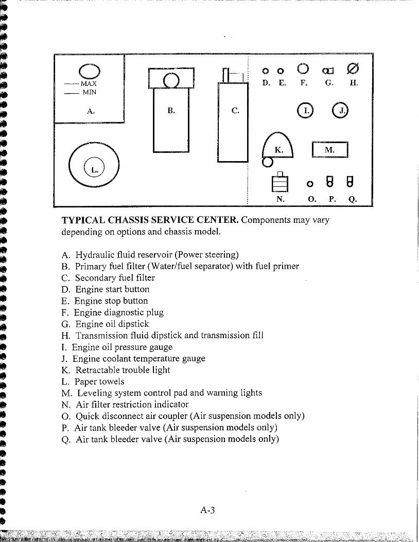
TYPICAL CHASSIS SERVICE CENTER. Components may vary depending on options and chassis model.
A. Hydraulic fluid reservoir (Power steering) B. Primary fuel filter (Water/fuel separator) with fuel primer C. Secondary fuel filter D. Engine start button E. Engine stop button F. Engine diagnostic plug G. Engine oil dipstick H. Transmission fluid dipstick and transmission fill I. Engine oil pressure gauge J. Engine coolant temperature gauge K. Retractable trouble light L. Paper towels M. Leveling system control pad and warning lights N. Air filter restriction indicator O. Quick disconnect air coupler (Air suspension models only) P. Air tank bleeder valve (Air suspension models only) Q. Air tank bleeder valve (Air suspension models only)
A-3
^^^mm^^^^^^^0^^^^^^K^^^MW9MUM9t9Ma^^BMr^m^m^^mm^iimmMmt.

TIRE CHARTS
GOODYEARTMES
TIRE SIZE- 9R22.5 TIRE MODEL- G159
PSI i 60 DUAL ! 2960
SINGLE] 3010
65 3120 3190
70 3270 3370
75 3410 3560
80 3SS0 3730
85 3690 3890
90 3820 4050
95 3950 4210
100 105
4350 4500
TIRE SIZE-265/75R 22.5 TIRE MODEL-G159
PSI DUAL
SINGLE
75 4040 4070
80 4205 4255
85 4370 4440
9 0 , (4525 t 4620
95 4685 4800
100 4805 4975
105
-• • ---
rsisoj ^ -y
110
5205
X TIRE SIZE-275/70R 22.5 TIRE MODEL-G159
PSI DUAL
SINGLE C453:
4885
90 4750 5080
95 4960
100 105 5165 5370 5530 ' 5750
110 5575 5965
115 5775 6185
120 5975
125 6175
6400 I 6610
TOYO TIRES
TIRE SIZE- 255/70R22.5 TIRE MODEL- M120Z
PSI DUAL
SINGLE
70 3195 3525
75 3415 3750
80 3640 3970
85 3860 4190
90 4080 4410
95 4190 4540.
100 4410 4805
105 4540 4940
110 4805 5205
115 5070 5510
PSI - POUNDS PER SQUARE INCH (COLD PRESSURE)
Dual and single weights are the actual weight carried by each tire. Weigh the axle and divide the weight by the number of tires on that axle to determine the weight carried by the tire.
EXAMPLE: A vehicle with 255/70R22.5 tires has a front axle weight of 9,080 pounds and a rear axle weight of 16,320 pounds. The weight carried by each ofthe front tires would be half of the axle weight, or 4,540 pounds. Looking at the chart, the proper inflation pressure would be 95 psi. The rear axle weight is distributed on two sets of duals, or four tires. Dividing the rear axle weight by 4 results in a tire weight of 4,080 pounds, so the inflation pressure should be 90 psi.
A-4

Chassis Lubrication Points - S-Series "Blue Streak" with Ellipti-Ride
> i
ALIGN SPEC CASTER 3 deg POS
CAMBER 1/8 deg POS
TOE IN 1/8" IN
(1) SPRING SHACKLE PINS
(2) TIE ROD END
(3) KING PIN TOP k BOTTOM
(4) FRONT WHEEL BEARING OIL LEVEL
(5) STEERING DRIVE SHAFT U-JOiNTS
(6) BRAKE ARM
(7) STEERING DRAG LINK
(8) DRIVE LINE SLIP JOINT k U-JOINTS
(9) FAN DRIVE BEARING

Chassis Lubrication Points - S-Series "Blue Streak" with Rayco Air
>
3E LEGEND
w
St=
ALIGN SPEC CASTER 5 deg PDS
CAHBER 1/8 deg POS
T K IN 1/8* IN
CI) TIE ROD END
Ql KING PIN TOP I BDTTOH
C3) FRONT WHEEL BEARING OIL LEVEL
C4) STEERING DRIVE SHAFT ti-JOINTS
(5) BRAKE ARH
C6> STEERING BRAG LINK
(7) DRIVE LUC SLIP JOINT I U-JOINTS
CB) FAN DRIVE BEARING

Chassis Lubrication Points - M-Series "Blue Max"
> i
ALIGN SPEC. CASTER 4 tfeg. POS.
CAMBER 1/8 deg. POS.
TOE m 1/8 * w
LEGEND:
-T-75T
(1) TIE ROD ENO
(2) KING PIN - TOP&BOTTOU
(3) FRONT WHEEL BEARING 0 1 LEVELS
(4) STEERING DRIVE SHAFT U-JOINTS
(5) BRAKE ARM
(6) STEERING DRAG LINK
(7) DRIVE LINE U-JOWTS k SLIP JOIMT
(8) FRONT RABUS ROO
(9) FAN DRIVE BEARING

Chassis Lubrication Points - B-Line
> oo
ALIGN SPEC CASTER A deg. POS CAMBER 1/8 deg POS TOE IN 1/8 ' IN
(1) TIE ROD END
C2) KING PIN TOP I BOTTOM
(3) FRONT WHEEL BEARING OIL LEVEL
(4) STEERING DRIVE SHAFT U-JOINTS
(5) STEERING DRAG LINK
(6) DRIVE LINE SLIP JOINT 8, U-JOINTS
(7) FAN DRIVE BEARING
ftiittftiftftftfiti itniinitiiti iti iniii iti i immn

ENGINE DOES NOT START TROUBLESHOOTING
DOES THE ENGINE TURN OVER WHEN
ATTEMPTING TO START?
NO
YES
ENSURE THERE IS ADEQUATE FUEL IN THE
FUEL TANK. ATTEMPT TO BLEED THE AIR FROM
THE FUEL SYSTEM FOLLOWING THE
INSTRUCTIONS UNDER THE CHASSIS
MAINTENANCE INSTRUCTIONS FOR
REPLACING THE FUEL FILTER.
STILL DOES NOT START
SEEK ADDITIONAL SERVICE ASSISTANCE
ATTEMPT TO START THE ENGINE WITH THE
BATTERY BOOST SWITCH HELD DOWN.
STILL DOES NOT START
WHEN TURNING THE KEY TO THE START POSITION,
DOES THE CHECK ENGINE AND AIR INLET LIGHTS ILLUMINATE?
YES NO
INSPECT THE INLINE FUSES LOCATED IN THE
BATTERY CABLE HARNESS BEHIND THE
CHASSIS BATTERIES FOR LOOSE CONNECTIONS,
CORROSION OR BLOWN FUSES.
STILL DOES NOT START
INSPECT THE CHASSIS BATTERIES FOR LOOSE
CONNECTIONS AND CORROSION; CLEAN AND
REPAIR AS NEEDED
A-9