
.. ti .. ti - DTICHIGH CURRENT COAXIAL PULSE TRANSFORMER FOR RAILGUN APPLICATIONS J. A. Pappas U. S....
5
HIGH CURRENT COAXIAL PULSE TRANSFORMER FOR RAILGUN APPLICATIONS J. A. Pappas U. S. Army Armament Research and Development Center EM Launch Research Dover, NJ 07801 H. D. Driga and W. F. Weldon Center for Electromechanics The University of Texas at Austin Austin, TX 78712 Summary A high-current ai r -core pulse transformer has been designed and fabricated. Its purpose is to re- duce the output impedance {nominally 100 mn) of a 50-kJ, capacitor bank for application to loads with impedances o.f about 25 mQ. The system wi 11 be used for high current component testing, specifi- cally experimental evaluation of the pressure of high- strength wrapped hypervelocity railgun sec- tions. The transformer will be part of a test stand con- sisting of five capacitor bank/transformer sets cap- able of del i ver i ng up to 1.6 million A to a load. The of the transformer is coaxial. The secondary coil consists of circ ular aluminum tubes connected in paralle l. The primary winding is contained within the tubes and is connected in series. The coaxi al geome- try was chosen for its high coupling coefficient and its mechanical simplicity. Design improvements and future refinements are also discussed . Introduction The electromagnetic launch facility at Picatinny Arsenal has five modular energy discharge capacitor banks, each with a storage capacity of 50 kJ, operat- ing at 10 kV, and capable of producing 100-kA peak current. It was desired to use these banks as the prime stores for a high magnetic pressure test stand. The purpose of th is fix t ure is to test various mater- ials as part of the design of the AGATE high pressure railgun system cur rently being developed. In order to achieve the high currents {> 1 MA) necessary to obtain barre l design pressure of 1,13.47 MPa, the rated bank current of 100 kA must be increased . An air-core coaxial pulse transformer is an attractive candida te for matching the high output impedance of the capacitor bank to the ra i lgun input. Among the benefits of the coaxial geometry are the high coupling coefficient, low external fi eld, simple electromagnetic •odel ing, compactness, and easy fabri - cation. A re la ted application for a pulse transformer has been proposed allowing the high current levels re- quired by mass accel erators from low current gener a- tors.! This would ease the design problems associated with current collection through sliding contacts. However, the proposed design does not assure tight coupling between the secondary and primary, which finally would affect the overall performance. The degree of coupl i ng for different types of pulse transformers is analyzed by Sadedin. Various geometries ar e considered such as a separate layer winding, a b ifi lar winding, a thin sheet, and a coaxia l cable . The analysis shows that the coaxial 538 cable type is by far the most effective in terms of high coefficient of cou pl i ng.2 The pulse transformer can perform more comp lex and subtler ro l es; e. g., a fast power crowbar system for fast theta-pinch experiments and the success of the experiments depends on atta ining extremely low values for the leakage inductance.3 But also, it acts as a t ransient energy storage and as an element in a specia l type of flux compression in order to produce the plasma init i ation pulse for ohmic heating in a thermonuc l ear fusion reactor.4 Theoretical The engineering perception about transformers is biased by the long experience with operation of such devices in sinusoidal regime . Equival ent circuits obtained through phasor methods do not apply to the transformers acting in pulsed regime and the operat i onal method must be used to find the response of the circuit to a un it step-function. Given response to the unit step - fu nction . using the convolution theorem one can find the response for any type of input. For the idealized transformer {fig. 1) the equations writ - ten us i ng Laplace transform are Solving for curren t s, 11 { s) " sL 2 -. R 2 - M2)s2 -. (R1L2 -. R 2 _Ll )s {L1L2 12{s ) - sM 2 2 {Rl Lz -. R 2 L 1 )s {Ll L 2 -M )s + sL 2 -. R2 l + 2as .. ti 0 -1 sM where, a = 52 -. 2as r:;--; 0 .. ti 0 + R1R2 -. R1R2
Transcript of .. ti .. ti - DTICHIGH CURRENT COAXIAL PULSE TRANSFORMER FOR RAILGUN APPLICATIONS J. A. Pappas U. S....

HIGH CURRENT COAXIAL PULSE TRANSFORMER FOR RAILGUN APPLICATIONS
J. A. Pappas U. S. Army Armament Research and Development Center
EM Launch Research Dover, NJ 07801
H. D. Driga and W. F. Weldon Center for Electromechanics
The University of Texas at Austin Austin, TX 78712
Summary
A high-current ai r -core pulse transformer has been designed and fabricated. Its purpose is to reduce the output impedance {nominally 100 mn) of a 50-kJ, 1,000-~F capacitor bank for application to loads with impedances o.f about 25 mQ. The system wi 11 be used for high current component testing, specifically experimental evaluation of the pressure li~its of high-strength wrapped hypervelocity railgun sections.
The transformer will be part of a test stand consisting of five capacitor bank/transformer sets capable of del iver i ng up to 1.6 million A to a load. The geo~try of the transformer is coaxial. The secondary coil consists of circular aluminum tubes connected in paralle l . The primary winding is contained within the tubes and is connected in series. The coaxi al geometry was chosen for its high coupling coefficient and its mechanical simplicity. Design improvements and future refinements are also discussed .
Introduction
The electromagnetic launch facility at Picatinny Arsenal has five modular energy discharge capacitor banks, each with a storage capacity of 50 kJ, operating at 10 kV, and capable of producing 100-kA peak current.
It was desired to use these banks as the prime ~ergy stores for a high magnetic pressure tes t stand. The purpose of thi s fixt ure is to test various materials as part of the design of the AGATE high pressure railgun system cur rently being developed.
In order to achieve the high currents {> 1 MA) necessary to obtain barrel design pressure of 1,13.47 MPa, the rated bank current of 100 kA must be increased . An air-core coaxi al pulse transformer is an attractive candidate for matching the high output impedance of the capacitor bank to the rai lgun input. Among the benefits of the coaxial geometry are the high coupling coefficient, low external f i eld, simple electromagnetic •odel ing, compactness, and easy fabri cation.
A re lated application for a pulse transformer has been proposed allowing the high current levels required by mass accelerators from low current generators.! This would ease the design problems associated with current collection through sliding contacts. However, the proposed design does not assure tight coupling between the secondary and primary, which finally would affect the overall performance.
The degree of coupl i ng for different types of pulse transformers is analyzed by Sadedin. Various geometries are considered such as a separate layer winding, a bifi lar winding, a thin sheet, and a coaxial cable . The analysis shows that the coaxial
538
cable type i s by far the most effective in terms of high coefficient of coupl i ng.2
The pulse transformer can perform more comp lex and subtler roles; e .g., a fast power crowbar system for fast theta-pinch experiments and the success of the experiments depends on atta ining extremely low val ues for the leakage inductance.3 But also, it acts as a t ransient energy storage and as an element i n a specia l type of flux compression in order to produce the plasma init i ation pulse for ohmic heating in a thermonuc lear fusion reactor.4
Theoretical
The engineering perception about transformers is biased by the long exper ience with operation of such devices in sinusoidal (har~onic ) regime . Equival ent circuits obtained through phasor methods do not apply to the transformers acting in pulsed regime and the operati onal method must be used to find the response of the circuit to a uni t step-function. Given response to the unit step- fu nction . using the convolution theorem one can find the response for any type of input. For the idealized transformer {fig. 1) the equations written usi ng Laplace transform are
Solving for current s,
11 { s) " sL2 -. R2
- M2)s2 -. (R1L2 -. R2_Ll )s {L1L2
12{s) -sM
2 2 {Rl Lz -. R2L1 )s {Ll L2 - M )s +
sL2 -. R2
l + 2as .. ti 0
- 1 sM
where,
a =
52 -. 2as
r:;--; andc.J=Va~ - c.J:
0
.. ti 0
+ R1R2
-. R1R2

Report Documentation Page Form ApprovedOMB No. 0704-0188
Public reporting burden for the collection of information is estimated to average 1 hour per response, including the time for reviewing instructions, searching existing data sources, gathering andmaintaining the data needed, and completing and reviewing the collection of information Send comments regarding this burden estimate or any other aspect of this collection of information,including suggestions for reducing this burden, to Washington Headquarters Services, Directorate for Information Operations and Reports, 1215 Jefferson Davis Highway, Suite 1204, ArlingtonVA 22202-4302 Respondents should be aware that notwithstanding any other provision of law, no person shall be subject to a penalty for failing to comply with a collection of information if itdoes not display a currently valid OMB control number
1. REPORT DATE JUN 1985
2. REPORT TYPE N/A
3. DATES COVERED -
4. TITLE AND SUBTITLE High Current Coaxial Pulse Transformer For Railgun Applications
5a. CONTRACT NUMBER
5b. GRANT NUMBER
5c. PROGRAM ELEMENT NUMBER
6. AUTHOR(S) 5d. PROJECT NUMBER
5e. TASK NUMBER
5f. WORK UNIT NUMBER
7. PERFORMING ORGANIZATION NAME(S) AND ADDRESS(ES) U. S. Army Armament Research and Development Center EM LaunchResearch Dover, NJ 07801
8. PERFORMING ORGANIZATIONREPORT NUMBER
9. SPONSORING/MONITORING AGENCY NAME(S) AND ADDRESS(ES) 10. SPONSOR/MONITOR’S ACRONYM(S)
11. SPONSOR/MONITOR’S REPORT NUMBER(S)
12. DISTRIBUTION/AVAILABILITY STATEMENT Approved for public release, distribution unlimited
13. SUPPLEMENTARY NOTES See also ADM002371. 2013 IEEE Pulsed Power Conference, Digest of Technical Papers 1976-2013, andAbstracts of the 2013 IEEE International Conference on Plasma Science. Held in San Francisco, CA on16-21 June 2013. U.S. Government or Federal Purpose Rights License
14. ABSTRACT
15. SUBJECT TERMS
16. SECURITY CLASSIFICATION OF: 17. LIMITATION OF ABSTRACT
SAR
18. NUMBEROF PAGES
4
19a. NAME OFRESPONSIBLE PERSON
a REPORT unclassified
b ABSTRACT unclassified
c THIS PAGE unclassified
Standard Form 298 (Rev. 8-98) Prescribed by ANSI Std Z39-18
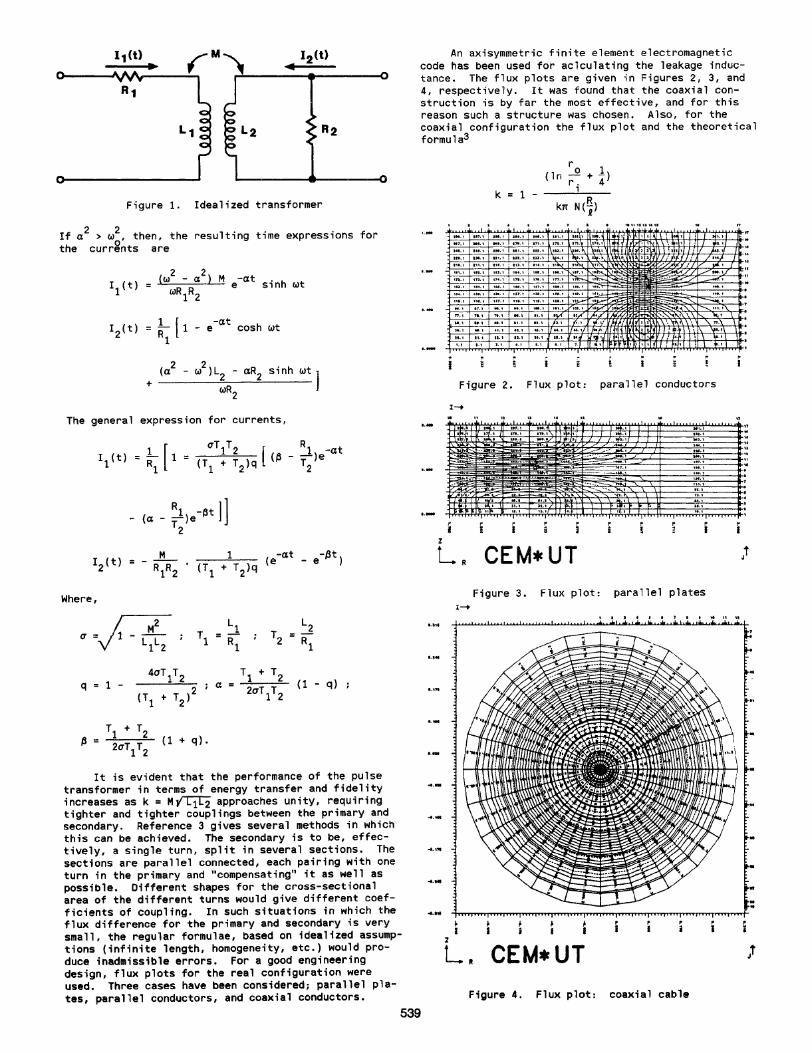
Figure 1. Idealized transformer
If a 2 > w2 , t hen, the resulting time expressions for t he currgnts are
1 ( -at I2 (t) = Rl 1 - e cosh wt
+ (a2
- w2
)L2 - aR2 sinh wt)
wR2
The general expression for currents,
1 [ uT 1 T 2 ( ~ -at = ~ 1 = (T + T )q (~ - T )e
1 1 2 2
Where,
q 1 - (1 - q)
It is evident that the performance of the pu lse transfor•er i n terms of energy transfer and fidelity increases as k = MflC1C2 approaches unity, requiring tighter and tighter coupl ings between the priaary and secondary . Reference 3 gives several methods in which this can be ach ieved. The secondary is to be, effectively, a single turn, spl it in several sections . The sections are paral lel connected, each pai ring with one turn in the primary and "cotnpensating'' it as well as possible. Different shapes for the cross-sectional area of the di fferent turns would give different coefficients of coupling . In such situations in wh ich the flux difference for the priaary and secondary is very small , the regular formulae, based on idealized assumpt ions (inf i nite length, honogeneity, etc .) would produce inad•issible errors . For a good engineering design, flux plots for the real configuration were used. Three cases have been considered; parallel pl ates, paral lel conductors, and coaxial conductors .
An axisymmetric fi ni te element electromagnetic code has been used for aclculating the leakage inductance. The f l ux plots are given in Figures 2, 3, and 4, respectively. It was found that the coaxi al construction is by fa r t he most effective, and for this reason such a structure was chosen. Also, for the coaxial configuration the f lux plot and the theoret i cal formula3
r + 1) (ln _.2
r . 4 k 1 -
1
kn N (B.) R
Figure 2. Fl ux plot: parallel conductors
Figure 3. Flux plot: para llel plates
Figure 4 . Flux plot : coaxial cable
539

where,
r 0 radius, outer conductor ri ~ radius , i nner conductor R radius of turn 1 length of the pulse t r ansformer
have the best agreement.
The slight disagreement with measured data can be expl ained be the transient skin effect which reduces t he equivalent inductances of both primary and secondary wind ings wh i le increasi ng the r esistance.
The forc.es are calculated using the 11agnet ic pressure on the conductors:
1 2 2 p ; 2~ (B (o,t) - B (x,t) ]
In the case of rapid pulses and transient field diffusion the trans ient depth of penetration is taken into account. Once again the coaxial cable construction is advantageous with regard to forces in cOMparison with all other competing topologies. However, there is an "unco11pensated" region i n the location of the connection of the secondary conductors to the busbars. Even i f the pulses are short, they still do not meet the r equire11ents for dynamic contain11ent where the time duration of the magnetic pressure pulse is short co•pared wi th the oscil lat i ng period of the container. Howeve r , we have extrapolated the criter ion and the resu l ts were satisfactory.
Oesign and Fabrication
Th i s transformer is shown schematica lly in Figure 5 and the major design parameters are presented in Table 1.
Table 1 . Design paramet ers
Maximum input current Pr imary turns Secondary t urns Maximum output current
100 kA 4
10 kA 400 kA
A simpl ified model of the the test bed was used to predict the performance of the transformer where, Lc is the internal inductance of the store, Rp and Rs are the lumped resistances of the pr imary and secondary, r espective ly. LL and RL comprise the load and were assumed to be constant . Y0 is the charge vol tage on the store , C. The coupling coefficient, k2c was in excess of 0.9. It was also assumed that the wall s of the secondary were thick enough that the field did not diffuse t hrough them in the di scharge t i•e.
Initi a l analyses showed that a smaller dia11eter primary cable could be used if the nu•ber of primary turns was increased. This l ed to the f inal configuration of a five turn pri11ary consist ing of 4/0, 16 kV jumper cable.
The secondary was chosen to be f ive pi eces of 6.033 -cm thick wall alUIIinu~ pipes bent i nto rings and connected in parallel. The dimensions of the secondary conductor were fixed by the r equired wa l l thickness and the ab ility of a shop to bend the pipe.
The perforMance of the pulse transformer consist i ng of these components was predicted us ing the model. The resul ts are summar i zed in Table 2.
540
SECONDARY-----, 6 l UUI 1111 ,AUU..It. C• o• AI TUt i NO WI:LDIO fO OU T..vf TUMIIULI
PRIMARY-------' I T~IUU IN PA,. ,U l i L 11 • v Ju .. •u c.uu
Figure 6. Pulse transformer
Tabl e 2. Predicted Per formance Characterist ics
Y0 8.50 kY R 6.64 mn R 6. 40 ~H I1 ., 100 kA I2 440 kA
TiMe-to-peak 122 ~s
The structur e of the transfor~er was designed to withstand the peak loads encountered during discharge. The material used for the secondary, annealed 6061 al u11inu11, has a yield strength approximately 40 ti•es t he maximum stress on the i nside walls of the tubes, so deformation of the secondary wi nding was not an important consider ation. The peak pressure exerted on t he output busbars , however, is considerably larger . The output of the transformer is 1.27-cm aluminum plate. The pl ates are restrained with 5-cm thick- wal l ste~l box beams bol ted together with a preload to mini•ize def lection. The peak force of repu lsion on the output plates is 45 kN distributed over an area of 21 mm2. A dynamic analysis showed that the deflection of the box beams shoul d be less than 0.03 m11.
The transformer proved to be simple to fabr icate, particular ly in light of t he fact that the coupl ing between the pr imary and t he secondary was required to be high. The a l u•inum tubes were bent into 180 degrees turns and welded t ogether to form the secondary helix. The method used to assembl e the secondary was to f i r st weld one half of the tubes to the common Figure 7. Welding at alignment pl ate busbar and the al ignment plate. The polyethylene insulator was then installed into the common plate by aligning i t over the openings, clamping it i n place and forming i t into s hape by heating the area around the openings (fig. 6). The remaining half of the helix was then assembled and welded. The two halves were 11ated and we lded at the align.ant plate.
The primary conductor was pulled t hrough the complet ed helix using 11e t hods common to conduit wiri ng . Electrical connect ion between the pri•ary and secondary, and primary and input plate was accomplished using thick wa ll copper tube crimped onto the primary cable and clamped to the buswork. The asse•bly was completed with the installation of the retainer clamps along the length of the connection plates (fig. 7).
Performance
The only test ing performed on the pulse transtor-r was to discharge the device into a short circuit . The energy stores used were a 180 JJF capacitor bank at 1 to 4 kV and a 1,100 J.IF capacitor bank at 5
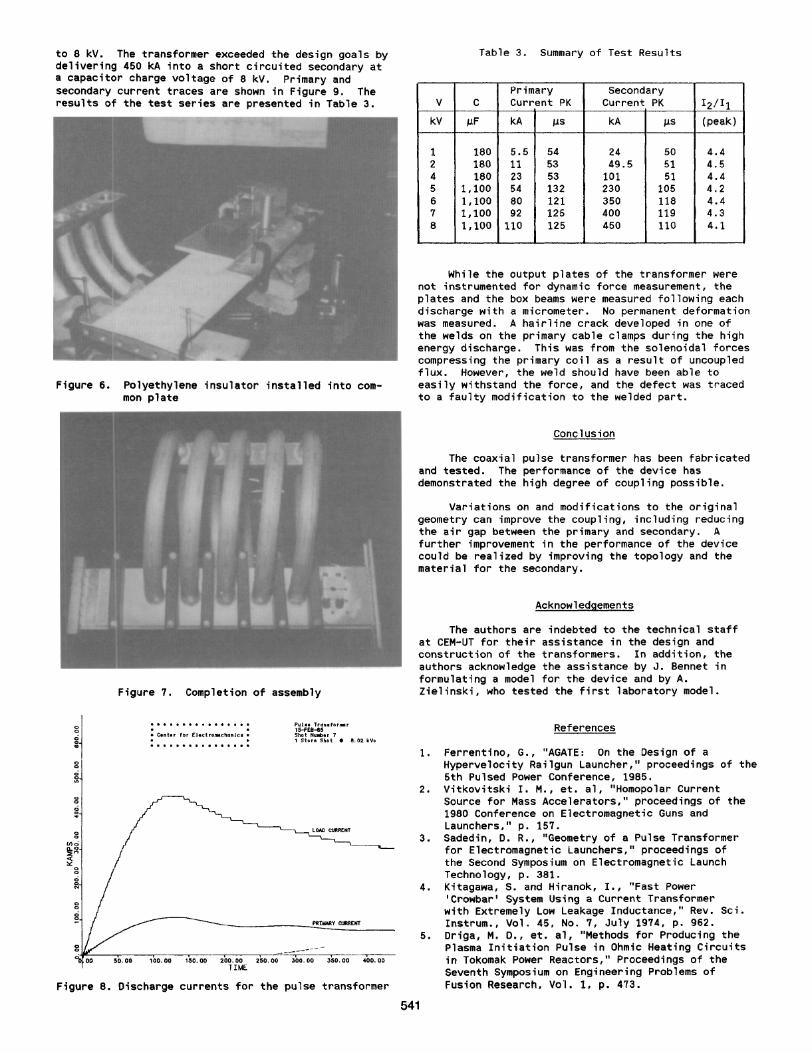
to 8 kV. The transformer exceeded the design goals by delivering 450 kA into a short circuited secondary at a capacitor charge voltage of 8 kV. Primary and secondary current traces are shown in Figure 9. The results of the test series are presented in Table 3.
Figure 6. Polyethylene insulator installed into common plate
Figure 7. Completion of asseably
................. . . • C.• t•r for (leetr.,.c.MIIIte• • . . .... ............
~¥.,-~-:--~r:-:c--.:-----.------.-~···==--:;.-=.-...,..----....,--......,..-•~ -~ -~ -~ -~ ~~ -~ ~~ T!t.E
Figure a. Discharge currents for the pulse transformer
Table 3. Summary of Test Resul ts
Primary secondary v c Current PK Current PK 12/It
kV p.F kA IJ.S kA ).IS (peak)
1 180 5.5 54 24 50 4.4 2 180 11 53 49.5 51 4.5 4 180 23 53 101 51 4.4 5 1,100 54 132 230 106 4 .2 6 1,100 80 121 350 118 4.4 7 1.100 92 125 400 119 4.3 8 1,100 110 125 460 110 4.1
While the output plates of the transformer were not instrumented for dynamic force measurement, the plates and the box beams were measured following each discharge with a micr~eter . No permanent deformation was measured. A ha i rline crack developed in one of the welds on the primary cable clamps duri ng the high energy discharge. This was from the solenoidal forces compress ing the primary coil as a result of uncoupled flux. However, the weld should have been able to easily withstand the force, and the defect was traced to a faulty modification to the welded part .
Conclusion
The coaxia l pulse transformer has been fabricated and tested. The perfor~ance of t he device has demonstrated the high degree of coupling possible.
Variations on and modifications to the origina l geometry can improve the coupling, including reduc ing the air gap between the primary and secondary. A further i mprovement in the performance of the device could be real ized by improving the topology and the material for the secondary.
Acknowledgements
The authors are indebted to the technical staff at CEM-UT for their assistance in the design and construction of the transformers. In addition, the authors acknowledge the assistance by J. Bennet in formulat i ng a model for the device and by A. Zieli nski, who tested the first laboratory model.
541
References
1. Ferrentino, G., "AGATE: on the Design of a Hyperve locity Ra ilgun Launcher," proceedings of the 5th Pulsed Power Conference, 1985.
2. Vitkovitski I. M., et . al, "Homopolar Current Source for Mass Accelerators," proceedings of the 1980 Conference on Electromagnetic Guns and Launchers," p. 157 .
3. Sadedin, D. R., "Geometry of a Pulse Transformer for Electr011agnetic Launchers," proceedings of the Second Sy111posium on Electromagnetic Launch Technology, p. 381.
4. Kitagawa , S. and Hiranok, I., ''Fast Power 'Crowbar' System Using a Current Transformer with Extremely Low Leakage Inductance," Rev. Sci. Instrum., Vol. 45, No. 7, July 1974, p. 962.
6. Driga, M. 0., et. al, "Methods for Producing the Plasma Initiation Pulse in Ohmic Heating Circuits in Tokomak Power Reactors," Proceedings of the Seventh SyNposium on Engineering Problems of Fusion Research, Vol. 1, p. 473.