Gear pump unit with reservoir Owner’s Manual - Containing ...

Rev. A

Dear Valued Customer,
On behalf of Sterling, we would like to express our gratitude and appreciation for choosing us as your supplier. We would also like to take this opportunity to introduce you to our complete offering of quality auxiliary equipment and services available for the process industries.
Full line of water and hot oil temperature control systems available in standard and custom configurations.
Air- and water-cooled chillers available in portable and central styles. Cooling tower systems, with full engineering capabilities.
Granulators, shredders, and size reduction systems. Available with vacuum take away and special hopper configurations.
Robotics, sprue pickers, and downstream automation. Custom end of arm tooling.
Quality OEM remanufacturing and updating of Sterlco water and hot oil temperature control units and components.
To obtain further information about any of these products, please feel free to call Sterling at either 1-800-783-7835 or 414-354-0970.

CONGRATULATIONS!
You are the proud owner of a Sterlco® Temperature Control System, the finest, most dependable unit available in todays market. Your Sterlco unit represents over 40 years of proven field service. We, at Sterling, are dedicated to manufacturing a temperature control unit that is second to none. Built by skilled craftsmen with the most modern and precise machinery available today. The simplicity of design and compactness engineered into the unit result in less maintenance and less floor space.
The Sterlco High Temperature Control Unit, designed and tested over a period of many years, represents one of the most significant advances ever in the field of self-contained, closed systems, portable units for heating natural or synthetic fluid and circulating it at controlled temperatures through molds, rolls, or jackets of processing equipment.
This Owner’s Manual is intended to provide a complete overview of the unit and to give you step-by-step guidelines for the safe operation, care and service of your unit. We recommend that you thoroughly read this manual before initial start-up.
These standard units may have many variations of optional features added to them, relative to the customer’s application or specific desires. The illustrations used are to help you identify certain parts by names and to understand our explanations, which will assist you later on in the Troubleshooting sections.
Units are warranted against defects in materials and workmanship for a minimum of one year from date of shipment. Any Sterlco unit which has been used contrary to specific operation instructions or materially altered, will not be covered by this warranty. Final determination of defects must be made at Sterling Inc.
By following the instructions in this manual and treating your equipment with care and respect due any precision equipment, you will be rewarded with years of uninterrupted, trouble free service.
Sterlco equipment must be attended while in use.
2

Table of Contents
Customer Service . . . . . . . . . . . . . . . . . . . . . . . . . . . . . . . . . . . . . 4
Conventions Used in This Manual . . . . . . . . . . . . . . . . . . . . . . . . 5
M2B Microprocessor Controller . . . . . . . . . . . . . . . . . . . . . . . . . . 6
Introduction . . . . . . . . . . . . . . . . . . . . . . . . . . . . . . . . . . . . . . . 6
Quick Start Instructions for the M2B Controller . . . . . . . . . . . 7
Installation. . . . . . . . . . . . . . . . . . . . . . . . . . . . . . . . . . . . . . . . 8
Environment . . . . . . . . . . . . . . . . . . . . . . . . . . . . . . . . . . . 8Electrical . . . . . . . . . . . . . . . . . . . . . . . . . . . . . . . . . . . . . . 8Security . . . . . . . . . . . . . . . . . . . . . . . . . . . . . . . . . . . . . . . 8Interface Panel . . . . . . . . . . . . . . . . . . . . . . . . . . . . . . . . . 9Indicator Lights . . . . . . . . . . . . . . . . . . . . . . . . . . . . . . . . . 9Input Keypad . . . . . . . . . . . . . . . . . . . . . . . . . . . . . . . . . . 10
Normal Operation Mode . . . . . . . . . . . . . . . . . . . . . . . . . . . . 11
Auto Vent. . . . . . . . . . . . . . . . . . . . . . . . . . . . . . . . . . . . . 11Tuning . . . . . . . . . . . . . . . . . . . . . . . . . . . . . . . . . . . . . . . 12Manual Tuning. . . . . . . . . . . . . . . . . . . . . . . . . . . . . . . . . 13
Ramp/Soak . . . . . . . . . . . . . . . . . . . . . . . . . . . . . . . . . . . . . . 14
Basic Theory of Operation Ramp/Soak . . . . . . . . . . . . . 14Sample Ramp/Soak Program . . . . . . . . . . . . . . . . . . . . . 17Starting Ramp/Soak . . . . . . . . . . . . . . . . . . . . . . . . . . . . 19
Options . . . . . . . . . . . . . . . . . . . . . . . . . . . . . . . . . . . . . . . . . 20
Remote Set Point . . . . . . . . . . . . . . . . . . . . . . . . . . . . . . 20Retransmission of Process Variable . . . . . . . . . . . . . . . . 21Second Set Point Input . . . . . . . . . . . . . . . . . . . . . . . . . . 21Flow Meter . . . . . . . . . . . . . . . . . . . . . . . . . . . . . . . . . . . 21Remote Thermocouple Monitor . . . . . . . . . . . . . . . . . . . 21Communications . . . . . . . . . . . . . . . . . . . . . . . . . . . . . . . 21SPI Protocol . . . . . . . . . . . . . . . . . . . . . . . . . . . . . . . . . . 24
Diagnostic Error Messages. . . . . . . . . . . . . . . . . . . . . . . . . . 26
Fault Reset Procedure . . . . . . . . . . . . . . . . . . . . . . . . . . . . . 26
High Temperature Oil Reconfiguration . . . . . . . . . . . . . . . . . 27
Field Calibration . . . . . . . . . . . . . . . . . . . . . . . . . . . . . . . . . . 28
Audit Temperature Inputs . . . . . . . . . . . . . . . . . . . . . . . . 28
Electrical Specifications . . . . . . . . . . . . . . . . . . . . . . . . . . . . . . . 31
General Specifications . . . . . . . . . . . . . . . . . . . . . . . . . . . . . . . . 32
Appendix A-Menu Selections . . . . . . . . . . . . . . . . . . . . . . . . . . . 33
Appendix B-Mounting . . . . . . . . . . . . . . . . . . . . . . . . . . . . . . . . . 37
Appendix C-Control Modes. . . . . . . . . . . . . . . . . . . . . . . . . . . . . 38
Appendix D-Blank Ramp/Soak Profile . . . . . . . . . . . . . . . . . . . . 43
Appendix E-Glossary of Terms . . . . . . . . . . . . . . . . . . . . . . . . . . 44
3

Customer Service
Your unit was engineered and carefully assembled to give you excellent quality and years of trouble-free operation. If an unknown condition occurs, Sterlco has a well trained customer service group to assist you. We suggest the following for quick service.
Sterling Inc.
The customer Service Group is available from 7 a.m. to 6 p.m. (CST), Monday through Friday. The numbers to call are:
(800) 783-7835(414) 354-0970
Fax (414) 354-6421
Before you call, be sure to do the following:
1. Refer to the Troubleshooting section of this manual.
2. Be sure to have this manual in front of you when you call.
3. Write down the symptoms or problem that you are experiencing.
4. Have your unit’s model number and serial number available when you call.
Sterling Return Goods Authorization (RGA)
In order to better serve our customer’s needs, we ask that before returning material or equipment of any kind, for any reason, that you call Sterling at 1-800-783-7835 for a return goods authorization number (RGA). This is a mandatory policy to help us identify returned goods, the reason for their return, and to help Sterlco expedite their processing. Failure to obtain this RGA number and mark it on the goods may result in their immediate return at your cost without being processed.
We thank you for your cooperation and understanding.
Heat transfer fluids must be drained and identified prior to shipment.
Please record your model identification number here for future reference. Refer to the description on Page 6 for more information.
00521601
4

Conventions Used in This Manual
Sterling, Inc. - Parent company of Sterlco®, Ball & Jewell®, and Sterltech®.
Sterlco - Manufacturer of water and oil temperature control systems, and water chiller systems.
BOLD CAP letters indicate a key on the M2B keypad.
“ ” text indicates the characters that are displayed on the LED windows. This manual shows the digital text as all caps, however, the actual readouts are a combination of caps and lower case letters.
CAUTION: A warning intended to prevent physical harm to the operator or equipment.
Note: Information to add clarity to the text.
The following illustration provides a reference for the side-bar illustrations:
∆
S Pis used to denote what is currently visable in theSETPOINT display.
is used to denote what iscurrently visable in thePROCESS display.
are used to denote a process variable.
and
5

M2B Microprocessor Controller
Introduction The M2B is a microprocessor based process controller designed for exclusive use with the Sterlco Temperature Control Units. The M2B monitors and maintains the temperature of the fluid in any given process to a selected set point using a unique proportional integral derivative (PID) auto-tuning program. The controller employs PID algorithms and fuzzy logic to automatically tune the system to heat or cool the fluid as required by the process.
The M2B has LED displays for set point and process temperatures. Controller status lights are provided for the following functions: cool, heater high/low, run, flow, return and delivery temperatures, and temperature differential.
The controller includes self-diagnostics to check hardware functions. Diagnostic lights are provided for the following functions: low fluid pressure, safety thermo, high/low alarms, delivery and return probes, and motor fail.
The M2B is panel mounted and has a membrane keypad with tactile feed-back. When properly installed with a sealing gasket, the M2B is safe for water washdown.
Figure-1
P7P8
HA2
T/C
DE
SolderedRibbonCable
KPUMP HIGH HEAT COOL
ALARM VENT LOW HEAT PURGE
COOL
LOW HEAT
SSR or 4-20MA PLUGIN MODULES H
IGH
HE
ATS
SR
ON
LYGB
EXT INT
CONTROLPOWERSELECT.
P5
P2
P6 P7
P3 P4
P8
P9
P1
0
A
Lowest Level Board contains Serial Label - lower left.
PROCESS OUTPUT/REMOTE S.P.PLUG IN MODULE
RS485/RS232PLUG IN MODULE
Flow Input
White ReturnRTD
Red DeliveryRTD
Black
Pre
ssS
witc
h
Ph
ase
Re
lay
2n
d
Se
tpo
int
Sa
fety
Th
erm
o
L1
OU
T
L1
CT
LR
L2 AL
AR
M
PU
MP
VE
NT
HI
HE
ATL
OW
H
EAT
CO
OL
Thermocouple
1 2 3 4 5 6 7 8 91
01
11
2
PU
RG
E
HE
AT
CO
OL
+ - + -
DAT
A +
DAT
A -
PV
OU
T
RM
T S
P
GRD
+5V
IN
P6P9P11 P10
+ - + -
6

Quick Start Instructions for the M2B ControllerThe quick start instructions can only be used provided the M2B is properly installed and wired.
Turn unit on - The “SETPOINT” and “PROCESS” LED displays will read ““.
Wait 3 sec. - The LED displays will read ““ and ““
Wait 3 sec. - The LED displays will read “ “and ““ where ““ equals the current process temperature.
Wait 1 to 5 min. for Vent sequence. - The LED displays will read ““ and ““ ““ equals the process setpoint. ““ equals the current process temperature.
The process is now running. The setpoint may now be adjusted for your installation. Press SETPOINT. Use ARROW to adjust.
Model Identification To determine the options that are included with the M2B, use the following configurator. The character “X” represents an option that is included.
∆
ON
3 sec.S P
S P
S P
3 sec.
1 to 5min.
S P
RUN
Options0 - STD.1 - RS485 SPI2 - RS485 GEN3 - 4-20 Heat Out4 - 4-20 Cool Out5 - 4-20 Heat/Cool6 - RS232 GEN.7 - Process Input 4-20 MA S.P. & P.V. XMIT
Temp Limit0 - 250 F1 - 180 F2 - 200 F3 - 450 F4 - 300 F5 - 400 F6 - 550 F7 - 650 F8 - Chiller
Base
00521601
Special Options = STD1="J" T/C2=Flow3=RAMP/SOAK (Null)4=Process Input 4-20 MA S.P. & P.V. XMIT5=2 Stage Set Point (Null)6=4-20 Heat Out7=4-20 Cool Out
= STDR = Rebuilt
X X X X XXX
030 (30 gpm)075 (75 gpm)
7

Installation
Environment Mount the instrument in a location that will not be subject to excessive temperature, shock or vibration. All models are designed for mounting in an enclosed panel.
When properly mounted in an enclosed panel using a gasket at the panel/controller interface, the keypad can be washed down with water. Do not use high pressure fluids.
Microprocessor based instruments require a “clean” source of power that is steady and free of noise. Electrical noise may be caused by line faults, power switching, motors, motor controllers, or power controllers containing SCR devices. Without a clean source, any microprocessor is prone to failure.
Electrical
CAUTION: Electrical noise is created by devices that are connected to a controls output load circuit. Field coils from contactors or solenoids are a common source of electrical noise. These conditions may interfere with the operation of the M2B controller.
If your power source is not from a clean line, your system can be protected by installing a Line Filter.
Where external contactors or solenoids are used with relay output instruments, an R/C Snubber Network should be used. The snubber installs easily directly across the field coil terminals of the relay or solenoid.
Do not run thermocouples, RTD’s or other class 2 wiring in the same conduit or area as power leads. Maintain separation between wiring of sensors, process signals and other power and control wiring.
Security Passwords are used to prevent access to critical menus. Four levels of security are provided. The display shows the current security level. Security levels are changed by changing the password value using the UP and DOWN arrow keys and pressing the ENTER key. Refer to the password table below for the correct value to enter for the security level desired. The SEC menu item security level may be viewed or changed at any time regardless of the present security level.
For example, to set the access level to ” ”, at the SEC menu item press the UP arrow key until the upper display shows the password, 101. Press the ENTER key. The display will blink, and return with the level value, ””, in the Process display.
8

Interface Panel
Figure-2
Note: Depressing the DISPLAY keypad, the function LED will stay on for thirty (30) seconds, then revert to the default delivery display.
Indicator Lights Status Lights
• RUN - Flashes while controller is auto-tuning. Glows steady during normal operation.
• HI HEAT - Fluid heaters are on Hi to rapidly raise the fluid temperature.• LO HEAT - Fluid heaters are at 50%.• COOL - Fluid temperature is above setpoint and is being cooled.
MenuSecurity Level
StatusDisplayed Value
When ViewedPassword Value To
Enter
HomeSecondary
Secure
LockedLockedLocked
1 110
HomeSecondary
Secure
UnlockedLockedLocked
2 101
HomeSecondary
Secure
UnlockedUnlockedLocked
3 011
HomeSecondary
Secure
UnlockedUnlockedUnlocked
4 111
∆
9

Display
• DELIVERY - The process display is showing the temperature of the outgoing fluid.
• RETURN - The process display is showing the temperature of the incoming fluid.
• ∆T - The process display is showing the difference between delivery and return temperatures.
• FLOW - The process display is showing the flow of the fluid in GPM or LPM. Must have optional flow sensor.
Alarms
• FLUID PRESSURE - Fluid pressure low. Unit shuts down and will resume operation when pressure is restored (disabled in oil units).
• SAFETY THERMO - Over temperature fault. Heater outputs are disabled. Pump continues to operate and the “cool” solenoid is energized. This is a fatal fault which requires the main power to be disconnected to reset the M2B.
• HI/LO ALARM - The alarms can be set individually via the keypads. The HI deviation is +200 oF (+93.3 oC) above the setpoint. The LOW deviation is -100 oF(-37.7 oC) below the setpoint. Oil temperature control unit alarms are set to “” as default and must be activated through the keypad if needed. The alarm settings can be changed to absolute, “” in the secondary menu. Alarms reset automatically.
• PROBE FAIL - A temperature sensing probe has failed. A delivery probe fail will display “” in the display. Failure of the return probe will display “”. The alarm will reset when the probe is replaced.
• MOTOR FAIL - Improper pump rotation, motor out of phase or thermal overload. This is a fatal fault which requires the main power to be disconnected to reset the M2B (water units only).
Input KeypadDepressing any program keypad (SETPOINT, HI ALARM , LO ALARM ) displays the stored value and allows the parameters to be adjusted. The following programmable features are allowed by the M2B.
• PROGRAM SETPOINT - Depress and hold the SET POINT keypad and either the UP or DOWN arrow to increase or decrease the set point display.
• PROGRAM HI ALARM - Depress and hold the HI ALARM and either the UP or DOWN arrows to set the alarm high limit. To disable the function, set the limit out of range or go into the secondary menu by depressing the UP and ENTER keys together. Use the index key to access the “” function. Use the UP or DOWN key to select “”. Depress ENTER to accept the function change.
Note : The controller will automatically program a high alarm of +200 oF (+93.3 oC) above set point and -100 oF (-73.3 oC) below setpoint.
10

• DISPLAY - Depressing the DISPLAY keypad scrolls through the display menu. Each depression indexes to the next available function. The display function will return to delivery temperature after thirty (30) seconds.
• UP ARROW - Increments a value, continued pressing will cause the value to gradually increment at a faster rate.
• DOWN ARROW - Decrements a value, continued pressing will cause the value to decrement at a faster rate.
• ENTER - Used only in conjunction with the home menu (index pad) or the secondary and secure menus. Pressing ENTER stores the value or the item changed. If not pressed, the previously stored value or item will be retained.
• INDEX - Pressing the INDEX key advances the display to the next menu item. The following functions are accessible by the INDEX key (see Appendix A for more information):– Tune– Fuzzy Logic– Auxiliary set point– Thermocouple Monitor– Flow Alarms– Autovent on-Off and Duration 1 to 5 min.– High/Low Heat Select– Ramp/Soak Run/Hold– Segment Time Remaining
• UP and DOWN ARROWs - Depressing the UP and DOWN arrows simultaneously activates an optional output normally used for purge options.
• UP and ENTER - Depressing the UP and ENTER keys simultaneously will access the “secondary menu”. The following functions are accessible in this menu (see Appendix A for more information):– oF/ oC Select,– Alarm: On-Off/Lo/Hi/Hi/Lo– Event– Ramp Soak,– Loop Break On-Off– Percent Output Display– Communications I.D.– Proportional Output/Input Scaling
Depress and hold for 30 seconds to enter the secure menu. All outputs are disabled.
CAUTION: Any changes will effect system operat ion.
Normal Operation Mode
Auto Vent: Display ““ in the set point display for duration of auto vent condition 1 to 5 minutes, adjustable. The auto vent feature is deactivated on high temperature oil units and chillers.
11

Tuning Note: The M2B is shipped with preset tuning parameters. To quickly adapt the M2B to your process, you may elect to tune the controller at start-up. Read this section entirely before initiating operation.
The M2B features Fuzzy Logic. Manual tuning is not necessary.
Fuzzy Logic is a term that describes the decision process within the controller. This controller has the programmed ability to “consider” inputs and change process information accordingly. One analogy would be a human trying to hit a target. The first attempt is recorded and the brain makes continual process corrections until an acceptable tolerance is reached.
The M2B controller also has multiple tuning conventions available to adjust to your process. Tuning choices are:
• Self • Nor• Manual PID Input • Fast• Slow
These tuning methods will speed up the Fuzzy Logic process.
Self-autotuning may be considered when initial start-up is performed or the mold and/or the process is changed.
CAUTION: The factory default for the M2B is automatic half/full heat. If an autotune cycle is completed do not switch to low heat without performing a new autotune cycle. Failure to autotune will result in poor control of the process. Subsequent changes from one heat setting to another require autotune to be run.
Initiate Autotuning:
The controller will evaluate the process and select the P, I, D and FuzzyLogic values. To maintain control:
1. Turn the control power switch to ON.
2. Press SETPOINT.
3. Use UP/DOWN arrows to adjust setpoint.
4. Allow completion of Autovent (“” in set point display).
5. Press INDEX keypad until “ ” appears in the display.
6. Press UP/DOWN arrows until “” appears in the display.
7. Press ENTER.
8. The Run Lamp will flash during the entire Autotune process.
9. Press INDEX keypad until “” and “” appear in the displays. Use the UP/DOWN arrows to select “” to cancel the tune.
10. Press ENTER.
Do not attempt to reprogram the M2B or depress any keypads while the “RUN” LED is flashing, as this will cancel the autotuning process.
For best Autotune results, start with a stabilized process temperature (no rapid rises or drops in temperature).
∆
ON
AutoventS
P
S
S
S
PS
AutotuneFinished
RUN
PS
12

Manual Tuning Procedure (Zeigler-Nichols PID Method):
This tuning method may be used if the spread between ambient temperature and process operating temperature is small. For best results, the use of a recording device is required when tuning with this method:
1. Disable the cooling output. Set “” in the scure menu to “”.
2. Set the reset (integral), the rate (derivative), and the fuzzy intensity (FPC) to zero. Set the proportional band (PBH) to 100.
3. Adjust setpoint to the desired value.
4. While monitoring the process temperature or recording device, decrease the proportional value by repeatedly halving the value until a small, sustained temperature oscillation is observed. Measure the period of one cycle of oscillation ”T”.
5. Divide the period of oscillation ”T” by eight, the resulting number is the correct rate, “” time in seconds. Multiply this number by four. This is the correct reset “” time in seconds.
6. Multiply the bandwidth value ”T” by 1.66, enter this as the new proportional “” value.
7. Reset the cool output “” to “”.
8. Reset the fuzzy intensity “ ” to 50.
S
S
S
S
S
S
S
S
P
P
P
P
P
P
P
P
S P
S P
S
S
P
P
S
S
P
P
S P
T
13

Manual Proportional Integral Derivative (PID):
Allows the operator to manually input P, I and D parameters into the controller. These parameters are fixed as long as the controller is in this mode.
Slo, Nor, or Fast:
Heat/Cool PID quick tune pre-determined parameters. Selectable through the keypad. See table below for Reference Settings.
Ramp/Soak The controller is provided with a 16 segment, front programmable
Ramp/Soak feature. Unused alarms can be programmed as a segment.
Caution: Do not operate the auto-tune while a ramp/soak function is operating.
Ramp/Soak is one of the many features that add process programming capabilities to the M2B controller. This section will deal only with the Ramp/Soak programming operation.
Basic Theory Of Operation Ramp/Soak
The M2B controller is user friendly. It offers an easy way to program a ramp. Instead of requiring the operator to calculate an approach rate, the M2B does the calculation automatically. The operator needs to program the target set point and the time desired to reach that set point. When the ramp segment is executed by the controller, it calculates the ramp required to reach the process temperature from starting set point to the programmed set point in the time allowed.
Dwells (or soaks) are ramp segments with target set point equal to starting process temperature. This allows for multistage ramps without wasting intermediate soak steps.
IMPORTANT! Test any program for best results before running production material.
Reference Settings For Manual PID Input
IndexSlow Response
SystemMedium Response
SystemFast Response
System
Air Cooled
Water Cooled
Air Cooled
Water Cooled
Air Cooled
Water Cooled
Pb1Heating Band
12 12 8 8 6 6
Pb2Cooling Band
12 20 8 12 6 10
dbDeadBand
0 0 0 0 0 0
rES Reset 20.0 15.0 7.0 5.0 3.0 2.0
rtERate
1.67 1.25 0.58 0.42 0.25 0.17
14

Caution: Make sure to run auto-tune before operating Ramp/Soak because Ramp functions will interfere with the operation of auto-tune.
Ramp/Soak Set Up
Before programming Ramp/Soak, evaluate your program on paper. To program Ramp/Soak function, enter the secondary menu (pressing UP and ENTER keys simultaneously).
• Press INDEX key repeatedly until “!!!!” appears. • Use the ARROW keys to change to ““(if it is on).• Press ENTER. • Press INDEX once, “” should appear. • Use the ARROW keys to change to “” (if it is off).• Press ENTER. • Press INDEX. “” should appear.• Skip this parameter for now, and press INDEX once more. “ ” will
appear. • Use the ARROW keys to select time base (seconds or minutes).• Press ENTER.• Press the INDEX key until “""""####” appears. • From this point, pressing INDEX will display the following items in the
following order:
“""""####”, “""""”, “""""""""” and “""""”---“$#$#$#$#”, “$$$$”---“####”, “”---“!!!!####”, “!!!!”
Alarms 1 and 2 display only if they are programmed as an event.
To eliminate repetition, each item will be described once.
S
S
S
S
P
P
S
S
S
S
S
S
Through 16 points
∆
15

• For the first ramp, set “"#"#"#"#“ to the required time. This value is in time units from 0 to 999 (seconds or minutes).
• Press ENTER.• Press INDEX, set “""""” to target set point for the first ramp. The units
of this value are the same as normal set point (SP1). • Press ENTER.• If alarm 1 is programmed as an event, then “""""""""” will appear when
INDEX is pressed. If alarm 1 is required for this segment, set “""""""""” for ON, if not, set for OFF.
• If alarms 1 or 2 are not programmed as an event, the “""""""""” and “""""” will not appear. If “""""""""” or “""""” are set to ON, alarm 1 or 2 will be active for the period of “"#"#"#"#” and “""""”.
• Set the segment times (“""""####”---”!!!!####”), segment set points (“""""”---”!!!!”), event alarms (“""""""""”---”"%"%"%"%”), if they exist.
• For the segments that are not used, set the segment times to 0, and segment set points to the same value as the last active set point.
• Event alarms may be set as necessary.• END is the last menu item for the Ramp/Soak function. END determines
what the controller does when the program has ended. • To set the program to repeat, select (“”).• If (“”) is selected, it is important to allow the process to return to the
same condition that existed when the program first started.• To hold last set point (“!!!!”), select (“”).• Turn off outputs at end of program, select (“&&&&”)• Press ENTER to accept your choice.
∆
S P
S P
S P
S P
Through 16 points
P
RUN
S
16

Sample Ramp Soak Program
Segment Prompt Function Time (Min.) Setpoint oF
1TI 1st Event 1
1SP 50
2TI 2nd Event 2
2SP 150
3TI 3rd Event 2
3SP 150
4TI 4th Event 2
4SP 100
5TI 5th Event 1
5SP 100
6TI 6th Event 2
6SP 50
7TI Un-Used 0
7SP Hold Last Setpoint 50
↓ Un-Used
GTI Un-Used 0
GSP 50
END Stay at present set pt. (gSP) HLd
END Turn off outputs at end of program Oof
END Repeat program at 1TI Lop
17

The following flow chart diagrams the sample Ramp/Soak procedure.
This program is now ready to run. See Starting Ramp/Soak.
S
S
S
S
S
S
S
S
S
S
S
S
P
P
P
P
P
P
P
P
P
P
P
P
S
S
S
S
S
S
S
S
S
S
S
S
P
P
P
P
P
P
P
P
P
P
P
P
Set the remaining points, 8-9 and A-G to zero
S
S
S
S
S
S
S
P
P
P
P
P
P
P
or
or
Enter the secondary menu. Follow the “Ramp/Soak setup” steps to reach
18

Starting Ramp/Soak • To run the program, enter the secondary menu and set the “” menu item to “”.
• Press ENTER. • Return to normal display by pressing SET POINT key or waiting for the
display to time out. • Press INDEX key once, “''''!!!!” will appear. • Use the ARROW keys to change to “((((” (if it is “”).• Press ENTER. The primary menu will change depending on the setting
of “” menu item in the secondary menu. If “” is off, there is no change. If “” is set to on, the primary menu has three additional information items added after “''''!!!!” appears:
• “""""” displays remaining time in the current segment
• “"#"#"#"#” displays total time of active segment
• “""""” displays the segment set point (“""""”---”!!!!”).
To exit primary menu, press SET POINT key.
∆
S P
S
P
No Change
S
P
Return to Normal
OFF
ON
S
S P
P
Remaining Time
Total Timeof Segment
Segment Set Point
STA
19

Options
Remote Set Point Installation
If the serial number date of the M2B is before 1/99 and the M2B controller was not factory equipped with a remote set point card, the controller must be configured to activate the option when field installed.
• Turn the control power off, cycle control power on. • During self test, hold the INDEX and ENTER keys until display shows
prom version number. • Release the keys and the display will show the prom version across
both displays. • Depress the INDEX key until “” “” appears. • If ”” is flashing, the remote set point is disabled. • If the “” is steady, the remote set point is enabled. • Press ENTER to change status. • Press INDEX twice. • Display “))))” “”.• Press the UP arrow to display “”. • Press ENTER.
Operation
The M2B is capable of an analog remote set point input. The operator can toggle the set point from local to remote input via the following sequence.
• Depress the UP and ENTER keys simultaneously. • Depress the INDEX key to scroll through the menu until “” appears
in the left display. • Depress the UP or DOWN keys to select remote set point “” or “”. • Depress the ENTER key to accept the selection.
Note: The M2B analog input is a 0-20mA current input. If a 4 to 20mA input is required, the low limit “” must be scaled using the following calculation:
y = mx+b
where y = “”
m = high limit - 0/analog high-analog low
x = analog high limit (20mA)
b = “”
“**** is Set Stop Limit High
“**** is Set Stop Limit Low
∆
S P
S P
P
S P
S P
S
PP
RUN
20

For Example: 250 oF = (250oF/20Ma - 4 mA) 20mA + b
-62.5 = b (””)
Retransmission Of Process Variable
The M2B is capable of re-transmitting the process output “''''” or the set point input “” via a 0-20mA analog signal. If a 4 to 20mA output is desired, follow the scaling calculation outlined in the remote set point section. Insert the low and high values for “” and “”.
Second Set Point Input
The M2B is provided with a secondary set point “” pre-programmed for 0 oF (-17.7 oC), but is adjustable. When an external switch contact is closed, the controller will switch to this set point and will display “” . This will occur when SP2 is set to 0 oF and the actual setpoint is any other value. The controller will revert to “” when the contact is released and unit returns to run mode.
Flow Meter The M2B is capable of displaying and alarming process flow in gallons per minute (GPM) or liters per minute (LPM), via a factory installed flow sensor. The M2B is capable of accepting numerous flow sensors.
Note: Please contact the factory if the flow readout oscillates or appears erratic for evaluation, calibration, and installation instructions.
The M2B is equipped with a software activated digital filter. The filter is adjustable from 0-100, the larger the number the greater the signal dampening. Consult the factory for further information and access.
Remote Thermocouple Monitor
Monitors type “J” thermocouple input. Depress INDEX key until “))))” appears. Temperature is displayed in process display window. See Figure-1 for location.
Communications The Sterling M2B controller can communicate with a host machine via a half or full duplex RS232 or RS485 communication link.
• Press and hold the UP and ENTER keys to access the secondary menu.
• Use the INDEX key until “++++” appears.• Use the UP or DOWN keys to select “ ” or “” .• Depress ENTER to accept your selection. • INDEX to “” to select the controller address “1 to 3FF”. • Depress ENTER to accept your selection.
Note : All data is sent and received in the ASCII hex character format, using 10 bits: 1 Start bit, 8 data bits, no parity and 1 Stop bit.
Any changes in the communication protocol should be made by qualified technicians.
Host will be used to describe the computer operating as the originator of communications. Instrument will be used to describe the process control(2) using this protocol. In the following examples, only Host and Instrument will be used.
P
S
S
S
RUN
21

1. The “L” (ASCII 4C hex) is used as a filter character in the examples below. The filter characters are specific. The filter character changes according to the Instrument’s address.
(ASCII 4C hex) = Instrument addresses 01 through FF
(ASCII 4F hex) = Instrument addresses 101 through 1FF
(ASCII 56 hex) = Instrument addresses 201 through 2FF
(ASCII 43 hex) = Instrument addresses 301 through 3FF
Addresses 00h, 200h and 300h should not be used. These are for Factory Service use only.
2. The checksum generated by the Host is obtained by adding all ASCII characters in hex, excluding the <stx>, filter character, and the <etx>. Only the lowest 8 bits are used. The checksum is inserted into the message between the data field and the <etx>.
Example: Host checksum calculation
32h 0100h 26h
<stx> L <addr> <---data---> <cksm> <etx>
02 4C 33 32 30 31 30 30 32 36 03
<----------cksm-------->
33+32+30+31+30+30 = 126h (use only the low byte)
3. The checksum generated by the Instrument is obtained by adding all ASCII characters in hex, excluding the <stx> and the <ack>. Only the lowest 8 bits are used. The checksum is inserted between the data field and the <ack>. Note that the filter character is included in the checksum calculation by Instrument.
Example: Instrument checksum calculation
32h 0100h 26h
<stx> L <addr> <---data---> <cksm> <ack>
02 4C 33 32 30 31 30 30 31 35 44 38 06
<-------------------cksm------------------->
4C+33+32+30+31+30+30 +31+35 = 1D8h (use only the low byte)
4. Checksums are generated for all Host commands
5. Checksums are generated for all normal Instrument responses. A checksum is not sent when errors are reported to the Host.
22

Command And Response Example Notations
1. [nu]: “not used” at present time, (for future expansion). Undefined data, data returned should not be used.
2. <Data>: These are ASCII characters shown in Hex notation. The upper case alpha character set is used for values A through F. (ASCII 46h - F, ASCII 33h - 3). Lower case is not used.
ASCII Control Character ASCII in hex Description
<stx> 02 Start of Text<etx> 03 End of Text<ack> 06 Acknowledgment
L 4C Filter Character00N Process Variable Value
100N Read Set Point Value200H Write Set Point Value
Error Messages Reported
Example:Checksum error detected by Instrument at address 32
Instrument responds to Host ’s last command with Error message
<stx> L <addr> N <error code> <ack>
32h N 02h
02 4C 33 32 4E 30 32 06
(Note the absence of Checksum)
N - ASCII character (4Eh) used to denote Error Present
Table Of Error Messages Possible From Instrument
<error code>
00 - Not used.
01 = Undefined command. Command not within acceptable range.
02 = Check-sum error on received data from Host.
03 = Command not performed by Instrument (option not enabled, restrictedread/write menu, check message)
04 = Illegal ASCII characters received in command. Instrument accepts only ASCII characters 0 through 9. A through F and a through f in data field.
05 = Data field error. Not enough, too many, or improper positioning ofcharacters in data field.
06 = Undefined command. Command not within acceptable range.
23

07 = Not used.
08, 09 = Hardware fault. Return to Factory for service.
10 = Undefined command. Command not within acceptable range.
SPI Protocol The Society of the Plastics Industry (SPI) communication protocol specifies a connection management Protocol, a packetized communication format, and communication error mechanisms passing commands and data between a host computer and a slave. A host computer initiates all communications. The protocol used corresponds to the 3.01 version of the SPI communication protocol specification dated October, 1990. The data is transmitted via a multidrop EIA-485 (half-duplex) hookup. The character format required is 1 start bit, 8 data bits, no parity and 1 stop bit.
The M2B controller will support a number of commands that will allow the host computer to retrieve status and assign set points. The commands correspond to a mold temperature controller device.
Commands Descriptions
(CMDl) (CMD2)
(20H) (20H) Echo poll — Controller integrity command. Return the 4 bytes of ASCIIassigned by the Echo Select command in an open format.
(21H) Echo Select — Controller integrity command. Supplies 4 bytes of ASCII in an open format that is to be returned when an Echo Poll command is received.
(22H) Version poll — Returns a version number (AABB = 0101) as 4 bytes of ASCII in an open format where:
AA = SPI assigned version level
BB = Vendor assigned version level
(30H) Set point poll — Returns the current process set point value in numericformat.
(31H) Set point select — Assigns a value to the process set point in numeric format.
(32H) Alarm, high temperature deviation poll —Return the high temperature deviation set point value in numeric format. This value when added to the process set point gives the temperature at which a high alarm will occur.
(33H) Alarm, high temperature deviation select —Assigns a value to the hightemperature deviation set point in numeric format.
(34H) Alarm, low temperature deviation poll —Returns the low temperaturedeviation set point value in numeric format. This value when subtractedfrom the process set point gives the temperature at which a low alarm willoccur.
(40H) Status process poll —Returns the status of the process as 16 flag bits in open format. The following bits are supported. The rest are set to 0.
Bit 0 — Processing
Bit 1 — Alarm, System
Bit 2 — Alarm, Process
24
Bit 3 — Alarm, Machine
Bit 4 — Alarm, High Temperature
Bit 5 — Alarm, Low Temperature
Bit 7 — Alarm, Low Pressure
Bit 9— Alarm, Low Flow
(42H) Status, machine 1 poll — Returns the status of the machine as 16 flag bits in open format. The following bits are supported. The rest are set to 0.
Bit 0 — Processing
Bit 1 — Alarm, System
Bit 2 — Alarm, Process
Bit 3 — Alarm, Machine
Bit 4 — Alarm, High Temperature
Bit 5 — Alarm, Low Temperature
Bit 7 — Alarm, Low Pressure
Bit 14 — Alarm, Phase Reversed or Lost
(44H) Status, machine 2 poll — Returns the status of the machine as 16 flag bits in open format. The following bits are supported. The rest are set to 0.
Bit 0 — Processing
Bit 1 — Alarm, System
Bit 2 — Alarm, Process
Bit 3 — Alarm, Machine
Bit 4 — Fault, Sensor, Delivery
Bit 5 — Fault, Sensor, Return
(48H) Mode, Machine Poll — Returns the current status of temperature control unit if the machine is On (1) or Off(0).
(49H) Mode, Machine Select — Commands the temperature control unit to turn On (1) or Off (0)
Bit 0— Machine On/Off
Bit 1 — Alarm Acknowledge
(70H) Temperature, to process poll — Returns the delivery temperature in numeric format.
(72H) Temperature, from process poll — Returns the return temperature in numeric format.
25

Diagnostic Error Messages
* Prior to Jan 1999 this was a flashing “”.
Fault Reset Procedure Reset Flashing “ ”
• Enter Secure 4 menu by pressing UP and ENTER simultaneously for 3 seconds.
• INDEX to “”• UP arrow until “+++” right display, press ENTER.• INDEX to “$)$)$)$)” left display, press ENTER, 9 flashes.• UP arrow until “,,,,,,,,” in right display.• Press DOWN and ENTER together to accept.• Display will flash “”, then “” steady.• Press SET POINT to exit to run.
Reload Factory Default
• Cycle control power to system Off and On.• While M2B controller is performing the self test, simultaneously depress
the INDEX and ENTER keypads together.• Index until “&” and “ ” appears in the display.• Press the DOWN and ENTER keypads simultaneously to accept the
factory default. Both displays will flash “&&&&&&&&” then “ “indicating re-boot is complete.
• The controller will automatically return to the run mode.
DISPLAY DESCRIPTION ACTION REQUIRED
Flashing “”
Ambient temperature out of range
Reduce ambient temperature at controller, consult factory.
Flashing* “”
Controller Ram violated,static discharge.
Controller must be reset to factory defaults. Consult factory for causes.
Steady“”
Delivery probe fail.Check probe connection or replace probe.
Steady“”
Return probe fail.Check probe connection or replace probe.
Steady“++++” “))))----”
4-20 mA input failed Check polarity.
P
S
P
S
RUN
∆
S P
S P
RUN
S P
26

CAUTION: The M2B controller automatically defaults to a 250 oF (121.1 oC) set-stop limit, water temperature control unit (TCU) configuration. All special configurations. i.e. 4-20 MA scaling, will be lost. Please record menu variables before performing a factory default. If you have an oil TCU, the controller must be re-configured for a high temperature 550 oF (287.7 oC) set-stop limit.
High Temperature Oil Re-configuration
• Depress and hold the UP and ENTER keypads simultaneously for five (5) seconds to enter the secure menu.
• “ ” will appear in the left display and “....” will appear in the right display.
• Depress the INDEX keypad until “))))” appears in the left display and “” appears in the right display.
• Depress the UP arrow until “” appears in the right display.• Depress the DOWN and ENTER keypads simultaneously to enter the
parameter.• Both the displays will flash “&&&&&&&&” then “ “ indicating the re-boot is
complete.• Depress the SET POINT keypad for short cut to the run mode, or, wait
thirty (30) seconds for auto exit to run mode.
∆
S P
P
S P
S P
S P
RUN
27

Field Calibration All Sterlco controllers are pre-calibrated at the factory. Due to the design of our input circuitry, the factory calibration should be valid for the life of the instrument. In the event recalibration is warranted, Sterlco recommends verifying input calibration specifications every twelve (12) months. Follow the calibration procedures outlined in your controller manual.
Audit Temperature Inputs
To audit the temperature probes for accuracy the following procedure should be followed:
Materials supplied by user
1. Input Signal testing
a. Millivolt Runup (MVR) with an output impedance of 100 ohms or less. Accuracy should be ± 1% or better.
b. Resistance decade box (RD) with an accuracy of ± 1% or better.
c. Frequency counter with an accuracy of ± 1% or better (0 to 2.5K mm. range).
d. Frequency generator capable of 50 to 200 Hz.
2. 4-1/2 Digit Digital Multimeter (DVM) with an accuracy of ± 0.05% or better.
3. Ambient Temperature Indicator with an accuracy of ± 0.05% or better.
4. Assortment of test leads.
Procedure
1. Power up Instrument and allow the M2B to warm up for 1 hour.
2. Hold the ENTER and UP Arrow keys for 5 seconds. The Menu will enter the SECURE MENU. The displays will read “ ” and “....”. If not, set the right display to “""""""""""""’, and press ENTER. The right display should blink and return to “....”. Press the INDEX key until you see “” and change it from “” to “” and press ENTER. INDEX to “))))####” and change it from “” to “” and press ENTER.
3. Press the INDEX key until you reach “”. Use the UP and DOWN arrow keys until “+++“shows in the right display. Press ENTER, and the two left digits of the left display will read “))))” (See Figure-3). This is CAL 0. Place the RTD connector into slot D (see Figure-4). Adjust the decade box to 99.114 ohms. The calibration value of the M2B should be between 18CA to 22CF (in hexadecimal - see Table 1). Press the ENTER and DOWN arrow keys if the value is within the acceptable range.
Figure-3
∆
P
S P
S
P
No
Yes
S P
S
Attach decade box
P
P
To Accept
P
To Accept
Repeat for 2c, 3c, 4c, 5c, 6c, 7c, 8c, 9c, ac, bc
RUN
Calibration #Calibration Value (Hexadecimal, 0-9, A-F)
28

4. Use the UP arrow key to go to CAL 1 (“""""))))”). Adjust the input to 2351.38 ohms. Make sure the calibration value is within the acceptable range (See Table 1) and press the ENTER and DOWN arrow keys simultaneously to accept.
5. Press the UP arrow key to go to CAL 2 (“))))”). Move the RTD connector from D to E (See Figure-4) and adjust the Input down to 99.114 ohms. Make sure the calibration value is within the acceptable range (See Table 1) and press the ENTER and DOWN arrow keys simultaneously to accept.
6. Press the UP arrow key to go to CAL 3 (“////))))”). Adjust the input to 2351.38 ohms. Make sure the calibration value is within the acceptable range (see Table 1) and press the ENTER and DOWN arrow keys simultaneously to accept.
Figure-4
7. Press the UP arrow key to go to CAL 4 (“....))))”). Place the millivolt connection into connector C (see Figure-4). Adjust your millivolt signal to 4.663 mV. Make sure the calibration value is within the acceptable range (see Table 1) and press the ENTER and DOWN arrow keys simultaneously to accept. Repeat this step for Cal 5 (“0)0)0)0)”), adjust the input for 73.953mV.
8. Press the UP arrow key to go to Cal 6 (“1)1)1)1)”). Place the wires for the remote setpoint input into the last 2 terminals of connector A2. See Figure-4. (+ to terminal 3 and - to terminal 4). Adjust your input to 1.224 mA. Make sure the calibration value is within the acceptable range (see Table 1) and press the ENTER and DOWN arrow keys simultaneously to accept.
9. Press the UP arrow key to go to CAL 7 (“,,,,))))”). Adjust the remote setpoint input to 19.721 mA. Make sure the calibration value is within the acceptable range (see Table 1) and press ENTER and DOWN arrow keys simultaneously to accept.
P7P8
HA2
C DE
K
A
Flow Input
RJC
29

10. Press the UP arrow key to go to CAL 8 (“))))”). The left display should read between 5400 and 6400 (hexadecimal).
11. Press the UP arrow key to go to CAP 9 (“$$$$))))”). Press the ENTER key. The right display will blink. Observe the temperature from the Ambient Temperature Indicator. Press the UP and DOWN arrow keys until you reach the ambient temperature. Press the ENTER and DOWN arrow keys to retain (display will blink to indicate value is accepted).
12. Press the UP arrow key to go to CAL A (“))))”). Place load (1.5K ohm resistor) into terminals 1 and 3 of connector K, see Figure-4. Connect frequency generator and frequency counter across the load. Adjust the input to 50 Hz (41 Hz for 75 GPM). Make sure the calibration value is within the acceptable range (see Table 1) and press the ENTER and DOWN arrow keys simultaneously to accept.
13. Press the UP arrow key to go to CAL B (“))))”). Now adjust the input to 200 Hz (131.5 Hz for 75 GPM). Make sure the calibration value is within the acceptable range (see Table 1) and press the ENTER and DOWN arrow keys simultaneously to accept. Press the INDEX key to exit. The calibration is now complete.
Table-1
Input Type Cal. # Input Value Calibration Value
RTD 0 99.114 ohms 18CA to 22CF
RTD 1 2351.38 ohms 8759 to B228
RTD 2 99.114 ohms 18CA to 33CF
RTD 3 2351.38 ohms 8759 to B228
TC 4 4.663 mV 18CA to 22CF
TC 5 73.953 mV 8759 to B228
Remote Input 6 1.224 mA 18CA to 22CF
Remote Input 7 19.721 mA 8759 to B228
Ambient 8 Ambient 5400 to 6400
Ambient 9 Ambient Temperature
Flow (30 GPM) A 50 Hz 18CA to 36D9
Flow (30 GPM) B 200 Hz 6d48 to 9816
Flow (75 GPM) A 41 Hz
Flow (75 GPM) B 137.5 Hz
30

Electrical Specifications
Temperature InputsT/C’s J, K, E, (Remote Sensing Only)
Input Type RangeJ: -100 to 1600 oF (-73 to 871 oC)K: -200 to 2500 oF (-129 to 1371 oC)E: -100 to 1800 oF (-73 to 982 oC)
Impedance 3 Meg ohms min.
RTD’s Pt1000 din 0.00385 ΩΩΩΩ/ΩΩΩΩ/ oC Range -328 to 1607 oF (-200 to 875 oC)Source current 200 µA
Flow InputMin. sig. 100 mV peak to peakImpedance 100k min.20 to 250 Hz.128 GPM (485 lpm) max.
Temperature/Flow input resolutionLow gain 2.1 uV
Signal Inputs (0.5mA @ 5Vdc Sense)Phase RelaySafety ThermoLow PressureRemote Set point Current: 0-20mA across 600OHM
Max., isolated to 500Vac
OutputsRelay: SPST, 1A @ 250 Vac resistive; 1A @ 250 Vac inductivePilot Duty Rating: 125VA
Hi/Lo Heat, Cool, Alarm, Purge, Pump, Vent (adjustable off to 5 min.)SSR: 1A@250Vac, isolated to 1500 Vac
Hi/Lo Heat, CoolCurrent: 0 to 20 mA across 600 ohms max., isolated to 500 Vac
Heat, Cool, Process OutputCommunications: RS232, RS485, Half and Full Duplex
RS 485SPI Half Duplex Only
Accuracy Temperature±0.25% of span ± least significant digit
Temperature Stability4uV / oC typical, 8 uV / oC maximum
Common Mode Rejection140 db minimum at 60 Hz.
Approvals
Ambient Temperature Range14 to 131 oF(-10 to 55 oC)0 to 90% up to 40 oC non-condensing, 0 to 50% at 55 oC non-condensing
31

Supply Requirements100 to 240 Vac, nominal, +10 to -15%, 50 to 400 Hz, single phase132 to 240 Vdc, nominal, +10 to -20%
Power Consumption5VA maximumDC Supply: +5V @ 30mA
General SpecificationsDimensions
Front Panel 5 1/2 x 9 inches (13.97 x 22.86 cm)Depth 3 3/4 in. (8.89 cm)
Weight20 oz. (622 g)
Displays and Indicators(2) 3-Digit Red Displays 0.56” (1.42 cm)Red LED’s for alarm functions
Pressure, Thermo, Hi/Lo Temp, Probe Fail, MotorGreen LED’s for status and display indication
Run, Hi/Lo Heat, Cool, Delivery, Return, Delta, Flow
ConnectorsPCB Interconnects
T and B JumpersSystem Connectors
WAGO 231 Series or equalCommunication and Current Output Connectors
WAGO Screw Pressure Plate
32

Appendix A
Hard Keys
Home (Index Keys)
Set Point Process Heat LowHeat High
SP1 ### Main Set Pt. 175 175
ALO ### Alarm Low -100
AHI ### Alarm High 200
Set Point Process Heat LowHeat High
SYS On/OFF System On or Off (Standby) On
Prg run/HLd note 1 Programmer Run/Hold
ti ### note 3 Program Segment Time remaining
#ti ### note 3 Program Segment Time
#SP ### note 3 Program Segment Set Point
tun Tune choice PID PID
SLF Self Tuning
Lrn YES/No Start Learn
dFa OFF, 1 to 7Damping factor 1=less, 7 = more ratio rate to reset
3 3
Pid Manual PID tuning
PbH 1 to 5000 Proportional Band 1 (deg or counts) 14 14
PbC 1 to 5000 Proportional Band 2 (deg or counts) 20 10
rES 0 to 999.9 Reset time in sec 1.5 1.5
OFS 0 to 99.9 Manual reset value in percent OFF OFF
rtE 0 to 99.99 Rate time in minutes 0.05 0.05
SLO Slow response process
nor Normal response process
FAS Fast response process
FPC 0 to 100Fuzzy intensity in percent 0 = off Impact fuzzy logic has on process
50 50
Fbd 1 to 400 Fuzzy Band in deg. or counts = to PBH 14 14
FrC 0 to 99.9Fuzzy rate of change in deg. or counts per second
2.5 2.5
PEA ### Peak PV, ENTER to reset to present PV
UAL ### Valley PV, ENTER to reset to present PV
2SP ### Auxiliary Set Pt. 0 0
tc ### Note 4 T/C Monitor Temp
FAL 0 to 100 Note 4 Flow Alarm Low 0 0
FAH 0 to 100 Note 4 Flow Alarm High 100 100
AUt OFF, 1 to 5 Auto vent cycle OFF, 1 to 5 min. 1.0 OFF
HiH On/OFF/AUt High Heat On/ Off/Auto AUt AUt
33

Secondary Menu (Up and Enter Keys)
* manual reset by simultaneously pressing index & down keys for 5 seconds.
Set Point Process Heat LowHeat High
Unt F/C Degrees F or C F F
AL1 OFF/Lo/Hi/HL/Eut Alarm (Off, Low, High, Hi.Lo, Event) OFF OFF
A1t AbS/dE Absolute or Deviation to SP1 dE dE
A1r OnF/HOL * Alarm Reset, auto reset/manual reset OnF OnF
A1i On/Off Power Interrupt OFF OFF
A1H On/OFFPower inhibit, suspend alarm until PV enters non-alarm condition
On On
A1S CLS/OPE Contact Closed/Open @ Alarm CLS CLS
A1L O on/oFF Lamp (on/off) contact closed Oon Oon
A1b On/OFF Alarm on Loop Break OFF OFF
Prg On/OFF Programmer ON/OFF (ramp/soak) OFF OFF
SEt On/OFFProg, values available for viewing & changing
OFF OFF
StA On/OFF note 2 Status of Prog. in Home Position OFF OFF
SEC 1 S/6OS note 2 Prog. time base (1 or 60 sec.) 1-S 1-S
#ti 0 to 9999 note 2 Segment time 0 0
#SP #### note 2 Segment Set Pt. 0 0
#A1 On/OFF note 2 Alarm 1 Event OFF OFF
#A2 On/OFF note 2 Alarm 2 Event OFF OFF
End Hld/Oof/LoP/SPt note 2 Programmer End (Hold, Off, Loop, SP) OFF OFF
A2L ### Alarm 2 Low
A2H ### Alarm 2 High
Ato On/OFF Auto/Man OFF OFF
rUP On/OFF Anti-Reset windup OFF OFF
Pct On/OFF Percent Output in SV display OFF OFF
LPb OFF, 1 to 9999 Loop Break time in sec. OFF OFF
POL ### Process Output Low 0 0
POH ### Process Output High 250 550
POS InP/SP1 Process Output Source InP InP
rSL ###4 mA = -62.50 mA = 020 mA = 250
Remote Set Pt. Low 0 0
rSH ### 250 Remote Set Pt High 250 550
rSP On/OFF Remote Set Pt On/OFF OFF OFF
L-r LOC/rE Comm Local/ Remote LOC LOC
Add 1 to 3FF Comm Address Viewable Only 32 32
34

Secure Menu (Up and Enter - 5 seconds)
Set Point Process
Water Temp.
Control Unit
Heat Low
Oil Temp. Control
UnitHeat High
SEC #### Security Code 4 4
FnC HL/HH/L Function (Lo/Hi heat Chiller) HL HL
Sto 0 to 100 Self Tune Offset Percent 0 0
InC -500 to +500 Input Correction 0 0
Fil OFF, 1 to 99 digital Filter value 0=off (electrical noise) OFF OFF
SP2 ### Second Set Pt (COOLING) 0 0
Pd2 On/OFF Link the I and D terms to PB2 ON ON
Art OFF, 1 to 99.99 Approach Rate outside PB1 OFF OFF
tci On/OFF T/C Monitor On/OFF OFF OFF
FLO On/OFF Flow Monitor On/OFF OFF OFF
FCY ### Flow in FREQ.
FSL 0 to 100 Flow Scale Low @ 25 Hz (CAL.) 6 6
FSH 0 to 255 Flow Scale High @ 225 Hz (CAL) 30 30
FLF 0 to 100 Flow Filter 2 2
SAF On/OFF Safety Thermo On/OFF ON ON
PrS On/OFF Pressure Input On/OFF ON ON
InP J-/CA-/E- T/C Input Type (J, K, E) J J
Int OFF,0.1 to 540.0 Input Fault Timer (min.) OFF OFF
Ot1
Output 1 type
OnF On/OFF
S1d #### On/OFF differential
1 to 80t Time proportioning cycle rate in sec. 20 20
#PuL 1 to 7Pulse curve value 1 = linear, 7 = most non-linear
PrP Voltage/Current proportional output
Ot2
Output 2 type
OnF ON/Off
S2d #### On/Off differential
1 to 80 Time proportioning cycle rate in sec. 15 15
#PuL 1 to 7Pulse curve value 1 = linear, 7 = most non-linear
PrP Voltage/Current proportional output
SEn OFF<1 to 4000 Sensor rate of change (cnts or deg. per sec) OFF OFF
SCL DEFAULTED Scale low 0 0
SCH DEFAULTED Scale high 250 550
SPL min - SCL Set Pt. low limit 0 0
SPH max- SCH Set Pt. high limit 250 550
S1S dir/rE Direct or Reverse Acting rE rE
S1L 0 to 90 Output 1 low limit 0 0
S1H 10 to 102 Output 1 high limit 100 100
35

Note 1: Only present when Pro = On
Note 2: Only present when SEt = On
Note 3: Only present when StA = On
Note 4: Only present when the option is active
Set Point Process
Water Temp.
Control Unit
Heat Low
Oil Temp. Control
UnitHeat High
S1C O on/off Lamp (on/off) contact closed Oon Oon
S2t AbS/dE Absolute of Deviation to SP1 dE dE
S2S dir/rE Direct or Reverse Acting dir dir
S2L 0 to 90 Output 1 low limit 0 0
S2H 10 to 102 Output 1 high limit 100 100
S2C O on/oFF Lamp (on/off) contact closed Oon Oon
AL2 OFF/Lo/Hi/HL/Eut Alarm (Off. Low, High, Hi/Lo, Event) OFF OFF
A2t AbS/dE Absolute or Deviation to SP1 dE dE
A2r OnF/HOL Alarm Reset (On/Off, Hold) OnF OnF
A2i On/OFF Power Interrupt OFF OFF
A2H On/OFF Power Inhibit On On
A2S CLS/OPE Contact Closed/Open @ Alarm CLS CLS
A2C O on/oFF Lamp (on/off) contact closed Oon Oon
A2b On/OFF Alarm on Loop Break OFF OFF
Add 1 to 3FF Note 4 Comm Address Hexadecimal (992/3) 32 32
nAt OFF, 1 to 99 Note 4 No activity Timer Minutes OFF OFF
Bau 300-19.2 K Note 4 Comm baud rate 9.6 9.6
36
Appendix B
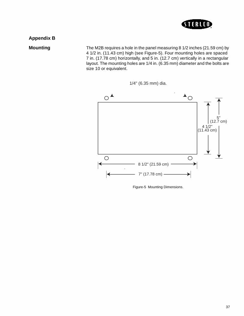
Mounting The M2B requires a hole in the panel measuring 8 1/2 inches (21.59 cm) by 4 1/2 in. (11.43 cm) high (see Figure-5). Four mounting holes are spaced 7 in. (17.78 cm) horizontally, and 5 in. (12.7 cm) vertically in a rectangular layout. The mounting holes are 1/4 in. (6.35 mm) diameter and the bolts are size 10 or equivalent.
Figure-5 Mounting Dimensions.
8 1/2" (21.59 cm)
7" (17.78 cm)
4 1/2"(11.43 cm)
5"(12.7 cm)
1/4" (6.35 mm) dia.
37

Appendix C
Control Modes:
On-Off: Action takes place if any deviation from set point occurs. The output is either full on or full off depending on the direction of deviation. Because the on-off controller can cause rapid cycling around the set point, hysteresis (dead band) is built in to suppress fast control action.
Temp
Proportional: Referred to as “P” or GAIN.
The controller switches the output based on the difference between the set point value and the process variable, and controls the output proportional to the deviation. This proportional action is active within a zone around the set point called the proportional band. The output becomes gradually smaller as the process variable nears the set point. Note that the process seldom reached the set point, but stabilizes at some deviation offset.
Temp
Integral: Referred to as “I” or RESET.
Expressed by integral time in seconds, the purpose of the integral action is to automatically compensate for any offset due to proportional action. The integral moves or resets the proportional band up or down to obtain set point. It is not intended to correct for process disturbances.
Temp
P.B. too small
TIME
S.P.P.V.
TIME
P.B.S.P.P.V.OFFSET
TIME
P.B.S.P.P.V.OFFSETPB SHIFTED UP
38

Derivative: Referred to as “D” or RATE.
Expressed as derivative time in seconds. The controller measures the rate of process increase or decrease and moves the proportional band to minimize overshoot. The change in the output is directly proportional to the rate of change in the process value.
Temp
Anti-Reset Windup: This function inhibits the integral action until the process variable is within the proportional band, thus reducing overshoot on start-up.
Direct/ReverseAction:
Direct action is used for cooling applications. The output of the controller increases with respect to an increase in the process value.
Reverse action is used for heating applications. The output of the controller decreases with respect to an increase in the process value.
Output
TIME
P.B.S.P.
P.B.
P.V.
TIME
100%
0%
P.B.
S.P.
P.V.
(COOL)(HEAT)
39

Adjustments:
Proportional 1) The lower the gain value (large proportional band), the less reactive the output becomes.
Temp
2) The larger the gain value (small proportional band) over responsive output, can lead to oscillation.
Temp
A proportional band which is correct approaches the set point as fast as possible while minimizing overshoot.
If a faster response is desired and process overshoot is not a problem, increase the gain value (over-damped system). If overshoot can’t be tolerated, decrease the gain value (under-damped system.)
Integral Integral action eliminates offset by adding to or subtracting from the output of the proportional action alone.
1) Short integral time means the controller corrects for offset quickly. If too short, the controller would react before the effects of previous output shifts, due to dead time or lag, are complete, could cause oscillation.
Temp
P.B. too large
TIME
S.P.P.V.OFFSET
P.B. too small
TIME
S.P.P.V.
TIME
P.B.S.P.
"I" is too short
40

2) Long integral time means the controller corrects for offset over a long time. If the integral time is too long, the offset will remain inactive, causing slow response or sluggish control.
Temp
Derivative: Derivative time is the amount of anticipatory action needed to return a process back to set point. In the case of a process upset, proportional only or proportional-integral action alone can’t react fast enough in returning a process back to set point without overshoot. Derivative action corrects for disturbances, providing sudden shifts in output which opposes the process disturbance.
Temp
1) A short derivative time means little derivative action. If the derivative is too short, the controller would not react quickly to process disturbances and may not attain set point.
2) A long derivative time means more derivative action. If the derivative time is too large, the controller would react too dramatically to process disturbances creating rapid process oscillation (alternating heat and cool continuously).
"I" is too long
TIME
P.V.S.P.
P.V.
TIME
P.V.RATE TIME
(RATE)DERIVATIVE ACTION
S.P.
41

TEMP
TIME
S.P.P.V.
LOAD
S.P.
S.P.
S.P.
S.P.
PROPORTIONAL
INTEGRAL
DERIVATIVE
RESULTANT PID
OUTPUT
OUTPUT
OUTPUT
OUTPUT
PID COMPONENTS REACTING TO A LOAD CHANGE
42

Appendix D
Drawing a Ramp/Soak Profile
Draw your ramp/soak profile on the record sheet below and fill in the associated information in the table below. This will give you a permanent record of your program and will assist you when entering the set point data.
Prompt Function Segment Value Prompt Function Segment Value
STRT SEG Start Seg. SEG7RAMP Ramp Time 7
END SEG End Seg. SEG8 SP Soak SP 8
RECYCLESNumber of Recycles
SEG8TIME Soak Time 8
SOAK DEVDeviation
ValueSEG9RAMP Ramp Time 9
SEG1RAMP Ramp Time 1 SG10 SP Soak SP 10
SEG2 SP Soak SP 2 SG10 TIME Soak Time 10
SEG2TIME Soak Time 2 SG11 RAMP Ramp Time 11
SEG3RAMP Ramp Time 3 SG12 SP Soak SP 12
SEG4 SP Soak SP 4 SG12 TIME Soak Time 12
SEG4TIME Soak Time 4 STATEProgram Controller
State
SEG5RAMP Ramp Time 5 PROG ENDController
Status
SEG6 SP Soak SP 6 RAMP UNITEngr. Unit for
Ramp
SEG6TIME Soak Time 6
43

Appendix E
Glossary of Terms
Alarm A condition that exists if the process variable exceeds internally stored alarm setpoints. Those setpoints can be:
Alarm Inhibit Prevents low setpoint alarm activation during cold startup applications.
Auto/Manual Alternative control conditions that can be selected within the controller.
Manual - An open loop condition, in which the power to the process is manually set and not influenced by the sensor.
Auto -A closed loop condition, in which the power to the process is automatically computed and set by the sensor output relative to the setpoint.
Bias Allows the operator to compensate for any difference between sensor temperature and the point to be measured. The process display and setpoint will be offset by the value entered in the Bias parameter in the input menu. Example: Desired temperature is 150 degrees. Sensor is adjacent to heater and reads 50 degrees higher than the actual process temperature. Enter bias of -50. Enter setpoint of 150. Process will display 150 even though sensor will be measuring 200 degrees.
Cycle Time The period of time in which the controller’s output completes an on-off cycle (proportional output type only). Example: Output type = mechanical relay; cycle time = 10 seconds; Output power = 50%; controller output = 5 seconds closed, 5 seconds open.
44

Deadband In on/off temperature control, it is the band above or below the setpoint where there is no output action, It has the effect of moving the apparent setpoint.
Derivative (Rate) Adjusts the controller gain quickly in response to load changes.
Derivative Action Is normally used to give a fast response to changes in process value and to improve process stability. Alternatively derivative action may be configured to act on the error signal which is useful in ramping applications.
Direct Action Control action such that the output increases as the process value increases.
Failsafe State Designates the percentage of power output that the controller defaults to after it detects a loop break condition and after the loop break time has elapsed.
Filter (in DisplayMenu)
Changes the filtering speed for the process value display only. It does not affect control. This parameter is mainly used to slow down the flickering of the display when the decimal position chosen is greater than zero.
Filtering (in InputMenu)
Sets the time period over which the process value is averaged.
Hysteresis In on/off temperature control, hysteresis represents the band where the output changes state from deactivated to activated. It prevents chattering around the setpoint and prevents rapid output cycling.
Hold The freezing of a running program, in time, for the duration of the condition.
Integral (AutomaticReset)
Slowly adjusts the position of the proportional band (range of power output) to eliminate offset error.
Local/Remote Alternative selections of the working setpoint. Either a value stored within the controller (local) or an analog signal brought into the controllers rear terminal (remote).
Loop Break A condition where the input is not changing or responding properly to the output action. This could be caused by a thermocouple or input failure, or a heater or load failure.
Loop Break Time The time interval from when the controller detects a loop break condition and the initiation of the failsafe state.
Manual Reset An adjustment that moves the proportional band up or down by a fixed percentage so that more or less power is applied at setpoint. It is used to eliminate offset error.
45

On/Off Output Type In a heating application, the controller applies 100% output power if the process temperature is below the setpoint and 0% at the setpoint. For a cooling application, the controller applies 100% output power if the process temperature is above the setpoint and 0% output power at the setpoint. There are only two output states: fully on and fully off.
Applications for On/Off Control: 1. When temperature oscillation is acceptable. 2. When constant cycling of mechanical devices is prohibited (compressors, blowers, etc.). 3. Under-powered processes.
Output Low Limit % Prohibits the controller’s output from going below the specified percentage.
Output High Limit % Prohibits the controller’s output from going above the specified percentage.
Output Relay Relays that are normally driven by the alarm output condition but can, as an alternative, be driven by segments of the program.
PID Output Type(Proportional -
Integral-Derivative)
The controller modulates output power by adjusting the output power percentage within a proportional band. Power is proportionally reduced as the process temperature gets closer to the setpoint temperature. PID control helps reduce overshoot on start-up, enhances stability, and compensates for process lag. The PID parameters are automatically calculated for a particular application during the autotune process. Applications for PID Control: 1. Where process temperature lags exist. 2. When load changes are present. 3. When overshoot is prohibited. 4. When very accurate control is required.
Program A preset profile of the controller setpoint made up of ramps and soaks, together with the sequence of state of the output relays.
Proportional Action The lower the gain value (large proportional band) the less reactive the output becomes proportionally to the error between setpoint and process value. The proportional band is the range of process value over which this linear gain action occurs before the output saturates at maximum or minimum. This is often expressed as a percentage of the instrument span. The gain of the instrument varies inversely as the proportional band increases. (see Manual Reset)
Proportional Band The band (expressed in degrees of temperature) in which the controller modulates its power percentage.
Ramp One segment of a program where the controller setpoint moves from one level to another linearly during a fixed period of time.
Reset An action which returns a completed or running program to the start condition, i.e. controlling SP1, SP2, or remote SP.
Reverse Action Control action such that the output decreases as the process value increases.
Run An action which starts a program running or restarts it from a hold condition.
46

Self Tune A facility which, when enabled, performs a number of ‘on’ and ‘off’ sequences of the controller output measuring the influence this has on the measured value. From these results the value of proportional ban, integral time and derivative time plus, under certain circumstances, cut back low, cut back high, heat cycle, cool cycle time and relative cool gain, for optimum control, are calculated and written into the commissioning mnemonics.
Soak A time entered into a program during which the setpoint remains constant.
Temperature Lag The product of thermal resistance and thermal capacity. Also defined as delay of the transmission of heat from the controlled element to the sensor caused by thermal mass of the process material and/or process container, or the distance between the control element and the sensor.
Upper Setpoint Limit Prohibits users from adjusting the setpoint higher than the selected value.
47

48