ST7000 Plus Autopilot Control Unit Owner’s · PDF fileChapter 6: Covers functional...
110
ST7000 Plus Autopilot Control Unit Owner’s Handbook Document number: 81118_1 Date: 20 January 1999
Transcript of ST7000 Plus Autopilot Control Unit Owner’s · PDF fileChapter 6: Covers functional...

ST7000 PlusAutopilotControl UnitOwner’sHandbook
Document number: 81118_1Date: 20 January 1999
118cover.p65 07/01/99, 12:401

118cover.p65 07/01/99, 12:402

Preface i
Raytheon Electronics, as part of its commitment to continuous improvement and updating, reservethe right to make changes, without prior notice, to the equipment, equipment specifications, and the
instructions contained within this handbook.
To the best of our knowledge, the information contained within this handbook was correctas it went to press.
A great deal of care has been taken to ensure that this handbook is as accurate as possible. However,liability cannot be accepted for inaccuracies or omissions.
Autohelm and SeaTalk are registered trademarks of the Raytheon Marine Company
WindTrim, AutoTack, AutoSeastate, AutoAdapt, AutoRelease and AutoTrim are trademarks ofRaytheon Marine Company
Copyright © Raytheon Marine Company 1998
118pref.p65 07/01/99, 12:401

ii ST7000 Plus Autopilot Control Unit Owner’s Handbook
118pref.p65 07/01/99, 12:402

Preface iii
ContentsPreface.................................................................................... xi
How this Handbook is Organised .................................... xi
Warranty ........................................................................... xi
Safety Information .......................................................... xii
EMC Conformance ........................................................ xiii
Chapter 1: Introduction ......................................................... 1
1.1 Overview ..................................................................... 1
1.2 Specification ............................................................... 2
Chapter 2: Basic Operation ................................................... 3
2.1 Key Functions ............................................................. 3
2.2 Display Layout ............................................................ 4
Bar Graph .................................................................... 4
Distance Units ............................................................. 5
2.3 Start Up Conditions .................................................... 5
2.4 Using Auto Mode ........................................................ 5
Safety ..................................................................... 5
Engaging the Autopilot ............................................... 5
Return to Hand Steering .............................................. 6
Changing Course ......................................................... 6
Dodging Obstacles in Auto Mode ............................... 7
Returning to the Previous Locked Heading ................ 8
Automatic Tack ........................................................... 9
AutoTack to Starboard ........................................... 9
AutoTack to Port .................................................... 9
118pref.p65 07/01/99, 12:403

iv ST7000 Plus Autopilot Control Unit Owner’s Handbook
Off Course Alarm ...................................................... 10
Operating Hints ......................................................... 10
Making Major Course Changes ........................... 10
Course Changes Under Autopilot Control ..... 10
Sailboats in Gusty Conditions ............................. 11
2.5 Using Manual Mode ................................................. 11
2.6 Setting Up Backlighting and Contrast ...................... 12
Backlighting .............................................................. 12
Contrast ..................................................................... 13
2.7 Data Pages ................................................................. 13
Waypoint names ........................................................ 14
2.8 Remotely Controlling ST60 and ST80 Instruments . 15
Chapter 3: Advanced Operation ......................................... 17
3.1 Operating in Track Mode .......................................... 17
Initiating Track Mode................................................ 17
Automatic Acquisition ......................................... 18
Manual Acquisition ............................................. 19
Cross Track Error ...................................................... 20
Tidal Stream Compensation ...................................... 21
Waypoint Arrival and Advance ................................. 21
Arrival .................................................................. 21
Skipping a Waypoint ...................................... 22
Advance ............................................................... 22
Dodges ...................................................................... 22
Initiating a Dodge Manoeuvre ............................. 22
Cancelling a Dodge Manoeuvre .......................... 22
118pref.p65 07/01/99, 12:404

Preface v
Safety ......................................................................... 23
Position Confirmation at the Start of a Passage .. 23
Verifying Computed Positions ............................. 23
Plot Frequency ..................................................... 23
Setting Waypoints ................................................ 23
General ................................................................ 23
3.2 Operating in Wind Mode (WindTrim) ...................... 24
Selecting Wind Mode ................................................ 24
Adjusting the Locked Wind Angle ............................ 25
Returning to the Previous Apparent Wind Angle
(LAST WIND) .......................................................... 25
Dodges ...................................................................... 26
Wind Shift Alarm ...................................................... 26
Using AutoTack in Wind Mode ................................. 26
Operating Hints ......................................................... 27
3.3 Adjusting Autopilot Performance ............................. 28
Changing the Response Level ................................... 28
Changing the Rudder Gain ........................................ 29
3.4 Alarms ....................................................................... 29
SeaTalk Failure .......................................................... 29
No Link ..................................................................... 29
Off Course ................................................................. 30
Wind Shift ................................................................. 30
Large Cross Track Error ............................................ 30
Drive Stopped ............................................................ 30
Data Not Received .................................................... 30
118pref.p65 07/01/99, 12:405

vi ST7000 Plus Autopilot Control Unit Owner’s Handbook
Waypoint Advance .................................................... 31
Low Battery ............................................................... 31
Watch Alarm .............................................................. 32
Route Completed ....................................................... 32
AutoRelease .............................................................. 32
Shallow ...................................................................... 33
Man Overboard (MOB) ............................................ 33
Chapter 4: Customising the System .................................. 35
Important ............................................................. 35
4.1 User Setup ................................................................. 35
Pilot Type .................................................................. 37
Compass Deviation Correction ................................. 37
Deviation Display ...................................................... 37
Heading Alignment ................................................... 37
Heading Mode) ......................................................... 38
Bar Selection ............................................................. 38
Rudder Calibration .................................................... 38
Popup Timeout .......................................................... 39
Auto Tack .................................................................. 39
Data Pages ................................................................. 39
Software Version Number ......................................... 41
4.2 Dealer Setup: Type 100/300 Course Computer ........ 41
Recommended Settings ............................................. 42
Pilot Type ............................................................. 42
Calibration Lock .................................................. 43
Rudder Gain ........................................................ 43
118pref.p65 07/01/99, 12:406

Preface vii
Rate Level ............................................................ 43
Rudder Offset ...................................................... 44
Rudder Limit ....................................................... 44
Turn Limit ............................................................ 44
Cruise Speed ........................................................ 45
Off Course Alarm ................................................ 45
AutoTrim ............................................................. 46
Power Steer .......................................................... 46
Drive Type ........................................................... 47
Rudder Damping ................................................. 47
Variation .............................................................. 48
AutoAdapt ........................................................... 48
Latitude ................................................................ 49
Wind Trim ............................................................ 49
AutoRelease ......................................................... 49
Response .............................................................. 49
Recording Calibration Settings ........................... 50
4.3 Setting Up For ST60 and ST80 Remote Control ...... 50
Instrument Grouping ................................................. 51
Setting Up Groups ............................................... 51
Grouping Standard Instruments .......................... 52
Grouping Maxiview Instruments ......................... 54
Chapter 5: Installation ........................................................ 57
5.1 Planning the Installation ........................................... 57
EMC Installation Guidelines ..................................... 57
Cabling ...................................................................... 58
118pref.p65 07/01/99, 12:407

viii ST7000 Plus Autopilot Control Unit Owner’s Handbook
5.2 Instrument ................................................................. 58
Siting ......................................................................... 58
Mounting Procedure .................................................. 59
Power ......................................................................... 60
Connections to the SeaTalk Bus ................................ 60
SeaTalk Cables .................................................... 60
Cable Types ......................................................... 60
Typical SeaTalk Cabling ...................................... 61
5.3 NMEA Interface ....................................................... 61
Cabling ...................................................................... 61
NMEA Cable Connectors ......................................... 62
NMEA Data .............................................................. 62
Transmission of NMEA Data on SeaTalk ................. 63
5.4 Functional Test (Repeater Unit) ................................ 63
Switch On .................................................................. 64
Navigation Interface (GPS, Decca, Loran) ............... 64
SeaTalk Interface ....................................................... 65
Chapter 6: Post Installation Procedures ........................... 67
6.1 Functional Test and Initial Calibration ..................... 67
Switch On .................................................................. 67
Initial Calibration ...................................................... 67
Operating Sense ........................................................ 68
Navigation Interface (GPS, Decca, Loran) ............... 68
Wind Transducer Interface ........................................ 69
SeaTalk Interface ....................................................... 69
EMC Conformance ................................................... 70
118pref.p65 07/01/99, 12:408

Preface ix
6.2 Initial Sea Trial .......................................................... 70
Automatic Compass Deviation Correction ............... 71
Further Heading Alignment Adjustment ................... 74
Checking Autopilot Operation .................................. 74
Checking the Rudder Gain ........................................ 74
Chapter 7: Maintenance ...................................................... 77
General ...................................................................... 77
Servicing and Safety ................................................. 77
Product Support ......................................................... 77
Chapter 8: Fault Finding ...................................................... 79
Index ...................................................................................... 81
118pref.p65 07/01/99, 12:409

x ST7000 Plus Autopilot Control Unit Owner’s Handbook
118pref.p65 07/01/99, 12:4010

Preface xi
PrefaceThis handbook contains information on the operation and installationof your ST7000 Plus. In order to obtain the best performance, pleaseread this handbook thoroughly.
How this Handbook is OrganisedThis handbook is divided into the following chapters:
Chapter 1: Introduces the ST7000 Plus Autopilot Control Unit, itsfeatures and use.
Chapter 2: Describes basic autopilot operation.
Chapter 3: Explains how to use Track and Wind modes and adjustautopilot performance. Also gives a summary of the ST7000 Plusalarms.
Chapter 4: Provides details on how to make adjustments to customisethe ST7000 Plus and associated autopilot to give optimumperformance on your vessel.
Chapter 5: Explains how to install the ST7000 Plus.
Chapter 6: Covers functional testing, initial calibration proceduresafter installation, and initial sea trials.
Chapter 7: Provides general maintenance procedures.
Chapter 8: Provides information to help you resolve any problemsyou may encounter with your autopilot.
An index is included at the end of this handbook, followed by atemplate for the installation of the control unit.
WarrantyTo verify the ownership of your new autopilot control unit, please takea few minutes to complete the warranty card. It is important that youcomplete the owner information and return the card to the factory toreceive full warranty benefits.
118pref.p65 07/01/99, 12:4011

xii ST7000 Plus Autopilot Control Unit Owner’s Handbook
Safety Information
WARNINGAlthough the ST7000 Plus is designed to give accurate and reliableperformance, it should serve only as an aid to navigation andshould never lead to the erosion of good seamanship. Alwaysmaintain a permanent watch and be aware of situations as theydevelop.
The following rules should always be observed:
• Maintain a permanent watch and regularly check all around forother vessels and obstacles to navigation – no matter how clear thesea may appear, a dangerous situation can develop rapidly.
• Maintain an accurate record of the vessel’s position either by use ofa radio navigation receiver or visual bearings.
• Maintain a continuous plot of position on a current chart. Ensure thelocked autopilot heading steers you clear of all obstacles. Makeproper allowance for Tidal Set – the autopilot cannot!
• Even when your autopilot is locked onto the desired Track using aradio navigation receiver, always maintain a log and make regularpositional plots. Radio navigation signals can produce significanterrors under some circumstances and the autopilot cannot detectthis situation.
• Make sure that all members of crew are familiar with theprocedures to disengage the autopilot.
• Ensure someone is present at the helm AT ALL TIMES, to takemanual control in an emergency.
• As the fluxgate compass used in the autopilot system is a type ofmagnetic compass, it is susceptible to disturbances in the localmagnetic fields, in the same way that a conventional ship’s compasswould be. It is therefore important that the fluxgate compass isinstalled and operated in a manner that will minimise the effects ofany such local disturbances.
Your Raytheon autopilot will add a new dimension to your boatingenjoyment. However, it is the responsibility of the skipper to ensure thesafety of the vessel at all times by careful observance of these basicrules.
118pref.p65 07/01/99, 12:4012

Preface xiii
EMC ConformanceAll Raytheon equipment and accessories are designed to the bestindustry standards for use in the leisure marine environment.
Their design and manufacture conforms to the appropriateElectromagnetic Compatibility (EMC) standards, but good installationis required to ensure that performance is not compromised.
118pref.p65 07/01/99, 12:4013

xiv ST7000 Plus Autopilot Control Unit Owner’s Handbook
118pref.p65 07/01/99, 12:4014
Chapter 1: Introduction 1
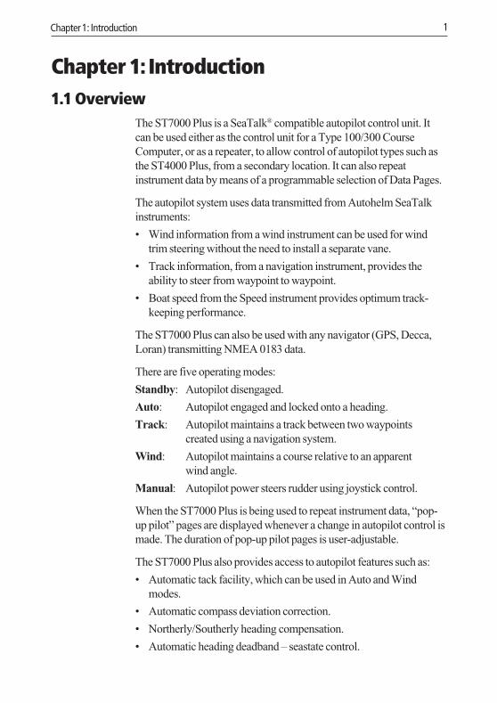
Chapter 1: Introduction1.1 Overview
The ST7000 Plus is a SeaTalk® compatible autopilot control unit. Itcan be used either as the control unit for a Type 100/300 CourseComputer, or as a repeater, to allow control of autopilot types such asthe ST4000 Plus, from a secondary location. It can also repeatinstrument data by means of a programmable selection of Data Pages.
The autopilot system uses data transmitted from Autohelm SeaTalkinstruments:
• Wind information from a wind instrument can be used for windtrim steering without the need to install a separate vane.
• Track information, from a navigation instrument, provides theability to steer from waypoint to waypoint.
• Boat speed from the Speed instrument provides optimum track-keeping performance.
The ST7000 Plus can also be used with any navigator (GPS, Decca,Loran) transmitting NMEA 0183 data.
There are five operating modes:
Standby: Autopilot disengaged.
Auto: Autopilot engaged and locked onto a heading.
Track: Autopilot maintains a track between two waypointscreated using a navigation system.
Wind: Autopilot maintains a course relative to an apparentwind angle.
Manual: Autopilot power steers rudder using joystick control.
When the ST7000 Plus is being used to repeat instrument data, “pop-up pilot” pages are displayed whenever a change in autopilot control ismade. The duration of pop-up pilot pages is user-adjustable.
The ST7000 Plus also provides access to autopilot features such as:
• Automatic tack facility, which can be used in Auto and Windmodes.
• Automatic compass deviation correction.
• Northerly/Southerly heading compensation.
• Automatic heading deadband – seastate control.
118ch01.p65 07/01/99, 12:401

2 ST7000 Plus Autopilot Control Unit Owner’s Handbook
• Waypoint advance feature.
• User Setup and Dealer Setup functions, to enable optimumperformance to be achieved for a wide range of different types ofvessel.
1.2 Specification• Power Supply: 10 to 15 V DC
• Current consumption:50 mA with display lamps off.120 mA with display lamps set at brightest level.
• Operating temperature: 0°C to +70°C (32°F to 158°F).
• Thirteen-button illuminated keypad.
• LCD display of heading, locked course, navigational, SeaTalk andNMEA data, with three levels of illumination.
• Two connections for SeaTalk.
• Input connection for NMEA.
118ch01.p65 07/01/99, 12:402

Chapter 2: Basic Operation 3
Chapter 2: Basic OperationThis chapter provides introductory operating information for yourST7000 Plus. Summary diagrams of the control key functions andscreen layout are given, plus instructions for tasks such as engaging theautopilot, operating in Auto mode, changing the display lighting, andusing Data Pages to display SeaTalk or NMEA data.
2.1 Key FunctionsThe autopilot is controlled using simple push-button operations, all ofwhich are confirmed with a beep. In addition to the main single keyfunctions, there are several dual key functions.
&
trackPress for Track mode from Auto
autoPress for Auto mode
disp
standbyPress for Standbymode
Course Change Keys-1 = Port 1˚+1 = Starboard 1˚-10 = Port 10˚+10 = Starboard 10˚
Press standby and auto for Wind mode
Press +1 and +10together for AutoTackto starboard
Press to accept waypoint advancePress for 1 second to skip waypoint
Press for 1 second for Last Heading
Press again to accept Last Heading
Press for 1 second for lamp control
Press and hold for Setup modes
D4206-1
respPress to displayresponse level
set crsPress to set course bearing
res'mPress to resume previous course
Press -1 and -10together for AutoTackto portPress -1 and +1together for responselevel
Press -1 and +1together for 1 secondfor rudder gain
Press standby and auto for 1 second to displayLast Wind. Press again to accept Last Wind
Press to adjust calibration parameters,response and gain
Press for next DataPage. When DataPage is displayed,press for 1 secondfor previous page
Press for 1 secondfor rudder gain
Note: The up arrow, down arrow, resp, track, set crs and res’mkeys can also be used to set up and control groups of Autohelm ST60and ST80 instruments (see Section 2.8, Remotely Controlling ST60and ST80 Instruments and Section 4.3, Setting Up For ST60 and ST80Remote Control).
118ch02.p65 07/01/99, 12:403

4 ST7000 Plus Autopilot Control Unit Owner’s Handbook
2.2 Display LayoutThe following illustration shows all the elements, together with a briefdescription, that make up the ST7000 Plus control unit LCD display.
CalibrationIndicator
Displayed oncalibration
pages
Bar GraphThe bar graph at the bottom of the display can be set up either as arudder position indicator, or as an error bar. If it has been set as an errorbar, the display depends on the current autopilot mode, as follows:
Mode Bar
Standby Rudder position indicator, in degrees.
Auto Heading error bar. Deviation from locked course, in degrees.
Track Cross track error (XTE) bar. Deviation from ground track. Thebar scaling is in the currently-selected distance units(displayed on pages showing distances).
Wind Wind angle error bar. Deviation from locked apparent windangle, in degrees.
Manual Rudder position indicator
118ch02.p65 07/01/99, 12:414

Chapter 2: Basic Operation 5
Distance UnitsDistance units are shown as either nm (nautical miles) or SM (statutemiles). If neither nm nor SM is displayed, the displayed distance is inkilometres.
2.3 Start Up ConditionsWhen the ST7000 Plus is first switched on, it is in Standby mode withthe display showing the vessel’s current compass heading.
You can return to manual steering at any time by pressing standbymomentarily, to return to Standby mode.
2.4 Using Auto Mode
SafetyAlthough autopilot control can considerably ease the task ofsailing a vessel, its use must never lead to the erosion of good-seamanship. ALWAYS maintain a permanent watch, no matterhow clear the sea may appear to be.
Remember, a large ship can travel two miles in five minutes - justthe time it takes to make a cup of coffee.
Engaging the Autopilot (AUTO)1. Steady the vessel on the required heading.
2. Press auto.
D4208-1
• In Auto mode, the display shows the locked autopilot heading.
118ch02.p65 07/01/99, 12:415

6 ST7000 Plus Autopilot Control Unit Owner’s Handbook
Return to Hand SteeringTo disengage the Autopilot and return to Standby, press standby.
• The ST7000 Plus returns to Standby mode with the displayshowing the vessel’s current compass heading.
• The previous autopilot heading is memorised and can be recalled(see Returning to Previous Locked Heading for details).
Changing CourseThere are two methods for changing to a new course. You can either:
• Set a new course directly (in Auto Mode)
or
• Set up the course you want (in Auto or Standby Mode) and apply itat a specific time (e.g. to make a course change at a predeterminedtime or location), after confirming that you have set the correctcourse and the direction of turn is correct.
In both cases, the +1 and +10 (starboard) and –1 and –10 (port) keysare used to change the locked heading, in increments of 1° and 10°.
To set a new course directly, in Auto Mode, use the +1 and +10(starboard) and –1 and –10 (port) keys as appropriate, to set theheading you want. The autopilot will turn on to the new courseimmediately it is set.
Example: a 30° course change to port = press –10 three times.
To set a new course and apply it at a predetermined time or location:
1. Press set crs. The SET COURSE screen is then displayed.
2. Use the +1 and +10 (starboard) keys or the –1 and –10 (port) keysas appropriate to set the heading you want. The autopilot will notaccept the new heading at this stage.
118ch02.p65 07/01/99, 12:416

Chapter 2: Basic Operation 7
3. If you do not want to accept the new course at this time, eitherpress the disp key or allow the display to timeout (10 seconds), toreturn to the pilot page.
4. To accept the new course at a later time, press set crs to re-displaythe new heading.
5. Press auto. A confirmation screen is then displayed. This showsthe new heading and the direction the autopilot will steer (PORT orSTARBOARD) to achieve the new heading.
6. Press auto again. The new heading is then applied and theautopilot assumes the new course.
Dodging Obstacles in Auto ModeIn order to avoid an obstacle when your vessel is under autopilotcontrol, select a course change in the appropriate direction (forexample, port 30° = press –10 three times).
118ch02.p65 07/01/99, 12:417

8 ST7000 Plus Autopilot Control Unit Owner’s Handbook
• When safely clear of the obstacle, you can resume the originalcourse by using the course change keys (for example, press+10 three times), or by using the previous locked heading.
Returning to the Previous Locked Heading (LASTHEADING)
Note: The previous locked heading is the most recent heading held for20 seconds or more.
If for any reason the vessel is steered away from the selected lockedheading (for example, executing a dodge manoeuvre or selectingStandby) you can return to the previous locked heading:
1. Press res’m. The previous locked heading is displayed for 10seconds and an appropriate direction-to-steer indicator flashes toshow you the direction the vessel will turn if this heading isaccepted.
2. To accept the previous locked heading and resume the originalcourse, press auto once within this 10 second period.
118ch02.p65 07/01/99, 12:418

Chapter 2: Basic Operation 9
If you do not press auto while the display is flashing, the currentheading will be maintained.
Automatic Tack (AUTOTACK)The ST7000 Plus can access an automatic tack facility that turns thevessel through a predetermined angle (the factory default is 100°) inthe required direction.
AutoTack to Starboard• Press the +1 and +10 keys together to tack to starboard.
AutoTack to Port• Press the -1 and -10 keys together to tack to port.
118ch02.p65 07/01/99, 12:419

10 ST7000 Plus Autopilot Control Unit Owner’s Handbook
Off Course AlarmThe off course alarm will sound if the locked autopilot heading and thevessel’s current heading differ for more than 20 seconds, by more thanthe alarm angle set in calibration (the factory default is 20°).
D4229-1
1. To cancel the off course alarm, press standby to return to handsteering.
2. Check whether your vessel is carrying too much sail, or whetherthe sails are badly balanced. Significant improvements in coursekeeping can usually be obtained by improving sail balance.
Operating Hints
Making Major Course Changes• It is sound seamanship to make major course changes only when
steering manually.
• Manual course changes ensure that obstructions or other vessels canbe cleared properly, and due account taken of the changed wind andsea conditions on the new heading prior to engaging the autopilot.
Course Changes Under Autopilot Control
It is important to understand the effect of sudden trim changes onsteering performance. When a sudden trim change occurs, due, forexample, to weather helm or sail imbalance, there will be a delaybefore the automatic trim applies rudder to restore the locked heading.This correction can take up to one minute.
Large course changes which change the apparent wind direction canproduce large trim changes. In these situations, the autopilot will not
118ch02.p65 07/01/99, 12:4110

Chapter 2: Basic Operation 11
immediately assume the new automatic heading, and will only settleonto course when the automatic trim has been fully established.
To eliminate this problem, the following procedure can be adopted forlarge course changes:
1. Note the required new heading.
2. Select standby and steer manually.
3. Bring the vessel onto the new heading.
4. Select auto and let the vessel settle onto course.
5. Bring the vessel to the final course with 1° increments.
Sailboats in Gusty ConditionsIn gusty conditions, the course may tend to wander slightly,particularly if the sails are badly balanced. A significant improvementin course keeping can always be obtained by improving sail balance.Bear in mind the following important points:
• Do not allow the yacht to heel over excessively.
• Ease the mainsheet traveller to leeward to reduce heeling andweather helm.
• If necessary, reef the mainsail a little early.
It is also advisable, whenever possible, to avoid sailing with the winddead astern in very strong winds and large seas.
Ideally, the wind should be brought at least 30° away from a dead runand, in severe conditions, it may be advisable to remove the mainsailaltogether and sail under headsail only.
Provided these simple precautions are taken, the autopilot will be ableto maintain competent control in gale force conditions.
2.5 Using Manual ModeIf your system is fitted with a joystick, the ST7000 Plus will enterManual mode when the joystick is used.
The ST7000 Plus will return to the previous operating mode when thejoystick button is released, or to Standby mode if you press thestandby key on the ST7000 Plus.
118ch02.p65 07/01/99, 12:4111

12 ST7000 Plus Autopilot Control Unit Owner’s Handbook
2.6 Setting Up Backlighting and Contrast
BacklightingTo set the backlighting level:
1. Press disp for 1 second, from any mode, to enter illuminationadjustment mode and turn the lights on.
1
D4211-1
2. Press the disp key the necessary number of times to cycle to therequired illumination setting. The settings are LAMP 3, LAMP 2,LAMP 1, LAMP OFF, LAMP 1, LAMP 2, LAMP 3 etc, with LAMP 3being the brightest setting.
The display times out to normal operation after 10 seconds of keypadinactivity.
Pressing any other key before the 10 second time-out will select themode assigned to that key (for example, auto selects Auto mode,standby selects Standby mode).
Notes: If other SeaTalk instruments or autopilot control units areconnected to SeaTalk, the illumination can be adjusted from theseunits.Any illumination adjustments are lost when the unit is switched off.The keys are still lit at a courtesy level when the display lighting is off.
118ch02.p65 07/01/99, 12:4112

Chapter 2: Basic Operation 13
ContrastTo set the display contrast:
1. With the autopilot in Standby mode, hold down the disp key for1 second to show the illumination adjust display.
2. Hold down the disp key for 1 second again, to display theCONTRAST adjust page.
3. Use the up and down arrow keys to set the required contrast level(from 1 to 15).
The display times out to normal operation after 10 seconds of keypadinactivity.
2.7 Data PagesThe disp key is used to cycle through Data Pages of SeaTalk orNMEA data. Once a Data Page is selected, this page becomes theprincipal autopilot display. The autopilot mode displays (Standby,Auto, Track Wind and Manual) then become “pop-ups”, and aredisplayed whenever the autopilot mode is changed or a course changeis made. The duration of pop-up pages is user-adjustable, from 1 to 10seconds. You can use Data Pages as follows:
• Press disp to display each Data Page in turn.
• When the last Data Page is cycled, the display returns to the currentautopilot mode display (for example, Standby).
• To return to a previous Data Page, press disp for 1 second within 2seconds of displaying a page. You can continue to move backwardsthrough the Data Page sequence in this way.
Up to 15 Data Pages are available using the disp key. The number ofpages, and the information displayed on each page, depends on theselections made in User Setup (see Section 4.1).
The following diagram shows the default Data Page settings.
118ch02.p65 07/01/99, 12:4113

14 ST7000 Plus Autopilot Control Unit Owner’s Handbook
D4212-1
• If the required data for a page is not available, dashes are displayedinstead of a value.
• Most displays are repeated data, and cannot be adjusted. Theexceptions are the INST REM (ST60/ST80 Instrument RemoteControl) and the MAXI REM (ST80 Maxiview Remote Control)pages (if selected for display). Setting up instructions for these aregiven in Chapter 4, Customising the System.
• The current autopilot mode is always shown at the top of thedisplay, and the autopilot bar graph remains in use.
Waypoint namesWhere waypoint names have been allocated, they are displayed on theDistance To Waypoint (DTW), Cross Track Error (XTE) and Bearing ToWaypoint (BTW) Data Pages.
D4326-1
118ch02.p65 07/01/99, 12:4114

Chapter 2: Basic Operation 15
Waypoint names of five characters or less (as at A above) are displayedat the right of the screen. Waypoint names comprising more than fivecharacters (as at B above) are centralised on the screen, alternatingwith the Data Page name.
When waypoint names have more than nine characters, only the firstnine characters are displayed.
2.8 Remotely Controlling ST60 and ST80 InstrumentsOn vessels where the ST7000 Plus is used with ST60 or ST80instrumentation, you can use the ST7000 Plus to control theseinstruments (both standard 110 mm, and Maxiview instruments).However, before attempting to operate ST60 or ST80 instruments inthis manner, ensure the instrument grouping has been defined (seeChapter 4, Customising the System).
D4325-1
Replication of the key-layout of the currently-selected standard instrument.Thus, for
example,if you press resp , the selected instrument responds as though its left-most
key has been pressed, and so on.
Controlling a standardinstrument
Controlling a Maxiviewinstrument
Chapterselect
Pageselect
Select instrument
All instrument types
118ch02.p65 07/01/99, 12:4115

16 ST7000 Plus Autopilot Control Unit Owner’s Handbook
To operate ST60 or ST80 instruments from ST7000 Plus:
1. Select either the INST REM Data Page (for control of standardinstruments) or the MAXI REM Data Page (for Maxiviewinstruments).
2. Using the summary of control functions shown in the followingillustration, carry out the required instrument control functionsfrom your ST7000 Plus.
Note: The manner used to show a currently-selected instrumentdepends on the instrument type:
• On ST80 instruments, the characters are displayed in inverse video(i.e. white characters on a black background).
• On ST60 digital instruments, a REMOTE legend is displayed.
• On ST60 analogue instruments, either one or both of the TRUE/MAGor TRUE/APP annunciators flash on the digital display.
118ch02.p65 07/01/99, 12:4116

Chapter 3: Advanced Operation 17
Chapter 3: Advanced OperationThis chapter provides information on:
• Operation in Track mode.
• Operation in Wind mode (WindTrim).
• Adjusting the response level and rudder gain.
• Alarms.
3.1 Operating in Track ModeTrack mode is used to maintain a track between two waypoints createdon a GPS, Decca, or Loran navigation system. The autopilot will thencompute any course changes to keep your boat on track, automaticallycompensating for tidal streams and leeway.
The ST7000 Plus can receive cross track error (the distance your vesselis from a planned track) from:
• A SeaTalk navigation instrument or chartplotter
or
• A non-SeaTalk navigation system transmitting data in theNMEA 0183 format – this can be connected directly to the ST7000Plus NMEA input, as described in Chapter 5, Installation.
Track mode is selected by pressing the track key, but can only beselected from Auto mode. You can return to either Auto or Standbymode from Track mode, as follows:
• Press auto to leave Track mode and return to Auto mode.
• Press standby to leave Track mode and return to manual steering.
Note: The ST7000 Plus control head can be programmed to displayvarious pages of navigation data, such as XTE, BTW etc. Please refer toChapter 4 for details.
Initiating Track ModeWhen initiating Track mode, the track can be acquired in one of twoways:
• Automatic acquisition, when cross track error and bearing towaypoint data are available.
• Manual acquisition, when cross track error is the only availabledata.
118ch03.p65 07/01/99, 12:4117

18 ST7000 Plus Autopilot Control Unit Owner’s Handbook
Automatic AcquisitionAutomatic acquisition can only be achieved if the pilot is receivingcross track error and bearing to waypoint information (via SeaTalk orNMEA 0183). It is initiated as follows:
1. Bring the vessel to within 0.1 nm of track.
2. Press auto.
3. Press track to enter Track mode, with the current locked headingdisplayed.
After a short delay for data acquisition, the Waypoint Advance alarmwill sound, and the display will show the current bearing to waypointalternating with the direction in which the boat will turn.
Note: If the vessel is further than 0.3 nm from the track, the LargeCross Track Error alarm will sound. Press standby to cancel thealarm, hand steer closer to the track, and press auto and track again.
4. Check that it is safe to turn onto the new course.
5. Press the track key. The boat will turn on to the new course andthe alarm will be cancelled.
118ch03.p65 07/01/99, 12:4118

Chapter 3: Advanced Operation 19
PreviousHeading
D3505-1
The display shows the new bearing to waypoint.
Manual AcquisitionFor manual track acquisition, when only cross track error data isavailable:
1. Steer the vessel to within 0.1 nm of track.
2. Bring the heading to within 5° of the bearing to the next waypoint.
3. Press auto.
4. Press track to enter Track mode.
The display shows the locked pilot heading.
Note: At low speeds, the effect of tidal streams is far more significantthan at higher speeds. Provided the tidal flow is less than 35% of thevessel’s speed, no noticeable difference should occur in theperformance of Track mode. However, extra care should be takenduring manual acquisition, as follows:
• Ensure that the vessel is as close as possible to track, and thedirection made good over the ground is as close as possible to thedirection of the next waypoint, before selecting Track mode.
118ch03.p65 07/01/99, 12:4119

20 ST7000 Plus Autopilot Control Unit Owner’s Handbook
• Make positive positional checks at regular intervals, especially ifnavigational hazards are close by.
Cross Track ErrorCross track error (XTE) is the distance between the current positionand a planned route. This is displayed in nautical miles (nm), statutemiles (SM) or kilometres, and is taken directly from your navigator.
The Large XTE alarm sounds if the XTE exceeds 0.3 nm.
• The direction of the error is identified as Pt (port) or Stb (starboard).
• To cancel the alarm, either press standby to leave Track mode andreturn to Standby mode, or press auto to return to Auto mode.
Note: If the Large Cross Track Error alarm sounds, it is usually anindication that the cross tide is too great for the vessel’s current speed.
118ch03.p65 07/01/99, 12:4120

Chapter 3: Advanced Operation 21
Tidal Stream CompensationUnder most conditions, Track mode will hold the selected track towithin ±0.05 nm (300 ft) or better. The autopilot takes account ofvessel speed when computing course changes to ensure optimumperformance over a wide range of vessel speeds. If speed data isavailable, the ST7000 Plus uses the measured vessel speed. Otherwise,the Speed Over Ground (SOG) or specified cruise speed is used,depending on the calibration setting (see Dealer Setup in Chapter 4).
Vessel's speed
Vessel's
Waypoint Arrival and AdvanceIf your navigation receiver transmits valid NMEA waypoint numberand bearing to waypoint data, it is possible to advance from onewaypoint to the next by pressing track. In order for the waypointadvance function to work, there must be at least one characterdifference in the names of adjacent waypoints.
ArrivalAs the vessel passes the target waypoint, the navigation receiver selects(manually or automatically) the next target waypoint.
The ST7000 Plus detects the new target waypoint number, sounds theWaypoint Advance alarm and displays Waypoint Advanceinformation. This display shows the new bearing to waypoint and thedirection the boat will turn to acquire the new track.
118ch03.p65 07/01/99, 12:4121

22 ST7000 Plus Autopilot Control Unit Owner’s Handbook
To accept the new target waypoint, press track.
Skipping a Waypoint – SeaTalk Navigators Only
If you wish to advance to the next waypoint before you have arrived atthe target waypoint, press track for 1 second. The Waypointinformation for the next waypoint is displayed.
AdvanceWhile the waypoint advance alarm is sounding, Track mode issuspended and the autopilot maintains the current boat heading.
1. Check that it is safe to turn onto the new track.
2. Press the track key. This will cancel the waypoint arrival alarmand turn the boat towards the next waypoint.
Note: Unless the Waypoint Advance is accepted in the above manner,the alarm will continue to sound and the current heading will bemaintained.
DodgesFull control is still available from the keypad when the autopilot is inTrack mode.
Initiating a Dodge ManoeuvreIn track mode, dodge manoeuvres are accomplished by simplyselecting the desired course change using the course change keys(-1, +1, -10 or +10).
Cancelling a Dodge ManoeuvreOnce the hazard has been avoided, the course change selected for thedodge manoeuvre should be cancelled by selecting an equal course
118ch03.p65 07/01/99, 12:4122

Chapter 3: Advanced Operation 23
change in the opposite direction.
Note: Provided the vessel remains within 0.1 nm of track, there is noneed to steer back towards the track.
SafetyPassage making in Track mode removes the chores of compensatingfor wind and tidal drift, and will aid precise navigation. However, it isimportant to maintain an accurate log with regular plots.
Position Confirmation at the Start of a PassageAt the start of a passage, always confirm the fix given by the positiontransducer, using an easily identifiable fixed object. Check for fixedpositional errors and compensate for them.
Verifying Computed PositionsVerify the computed position with a dead reckoned position,calculated from the average course steered and the distance logged.
Plot Frequency• In open water, plots should be at least hourly on sail boats and more
frequently on power boats.
• In confined waters, or when potential hazards are near, plots shouldbe more frequent.
• Local variations in radio signal quality, and changes in the tidalstream, will produce deviations from the desired track.
Setting Waypoints• When setting waypoints, remember that deviations will occur.
• Thoroughly check along each track.
• Check up to 0.5 nm each side of the track to ensure that there are nohazards within the zone.
GeneralThe use of track mode will enable accurate track keeping even incomplex navigational situations. However, it cannot remove theresponsibility of the skipper to ensure the safety of his vessel at alltimes by careful navigation and frequent position checks.
118ch03.p65 07/01/99, 12:4123

24 ST7000 Plus Autopilot Control Unit Owner’s Handbook
3.2 Operating in Wind Mode (WindTrim)Wind mode (also known as WindTrim) allows the ST7000 Plus tomaintain a course relative to an apparent wind angle. It uses wind trimto eliminate the effects of turbulence and short term wind variations,and provides smooth precise performance under Wind mode operationwith minimal power consumption.
Wind mode uses the fluxgate compass as the primary headingreference and, as changes in the apparent wind angle occur, the lockedcompass heading is adjusted to maintain the original apparent windangle.
To use Wind mode, the ST7000 Plus must receive wind informationfrom one of the following sources:
• SeaTalk Wind instrument, connected to a ST7000 Plus via SeaTalk.
• NMEA wind information.
• Autohelm wind vane connected to a SeaTalk interface box.
Selecting Wind ModeWind mode can be selected from either Standby or Auto modes, asfollows:
1. Steady the vessel onto the required apparent wind angle.
2. Press standby and auto together to select Wind mode and lockthe current apparent wind angle.
• The locked heading is displayed along with the apparent windangle.
• The boat heading is adjusted by the pilot to maintain the lockedapparent wind angle.
118ch03.p65 07/01/99, 12:4124

Chapter 3: Advanced Operation 25
Adjusting the Locked Wind AngleThe locked wind angle can be adjusted by changing course using the-1, +1, -10 and +10 keys.
For example, to bear away by 10° when the vessel is on starboard tack,press -10 to turn the vessel 10° to port. The locked apparent wind angleand locked heading both change by 10°. The new apparent wind angleis maintained, and the locked heading adjusted by the autopilot asrequired.
Note: This method should only be used for minor adjustments to theapparent wind angle, since turning the boat affects the relationshipbetween the true and apparent wind angles. For major changes, returnto Standby mode, steer onto the new heading, and reselect Wind mode.
Returning to the Previous Apparent Wind Angle(LAST WIND)
If for any reason the vessel is steered away from the selected apparentwind angle (for example, a dodge manoeuvre or selecting Standby)you can return to the previous locked wind angle:
1. Press res’m to display the previous apparent wind angle (LASTWIND).
The LAST WIND text alternates with the previous wind angle anddirection (PORT or STBD). The previous locked heading isdisplayed, with an indicator to show you the direction in which thevessel will turn.
2. Check that it is safe to turn on to this course.
3. To accept this apparent wind angle, press standby and autotogether within 10 seconds.
118ch03.p65 07/01/99, 12:4225
26 ST7000 Plus Autopilot Control Unit Owner’s Handbook
If you do not accept the previous wind within this time, the autopilotlocks on to the current apparent wind angle.
DodgesFull control is still available from the keypad when the autopilot is inWind mode.
• Dodge manoeuvres are accomplished by simply selecting thedesired course change using the course change keys(-1, +1, -10 and +10). Both the locked heading and locked apparentwind angle are adjusted.
• Once the hazard has been avoided, you can reverse the previouscourse change, or return to the previous apparent wind angle(LAST WIND).
Wind Shift AlarmThe wind shift alarm sounds, and the text WINDSHIFT is displayed, if awind shift of more than 15° is detected.
1. Press standby to cancel the alarm and return to hand steering,and steer onto the required heading.
2. Press standby and auto together to return to Wind mode withthe new apparent wind angle.
Using AutoTack in Wind ModeThe automatic tack function tacks the vessel through a set angle (thefactory default is 100°). The locked heading can then be adjusted untilthe required apparent wind angle is achieved.
• To tack to starboard, press +1 and +10 together momentarily.
• To tack to port, press -1 and -10 together momentarily.
Note: In order to obtain optimum performance when using AutoTackin Wind mode, it is important that the wind vane is accurately centredwhen it is installed.
118ch03.p65 07/01/99, 12:4226

Chapter 3: Advanced Operation 27
Apparent Wind Angle
AutoTackAngle
Course adjustment maybe necessary to mirrorthe previous apparentwind angle
D4373_1
Operating Hints• Major changes to the selected apparent wind angle should be made
by returning to Standby mode, changing course manually, thenreselecting Wind Mode.
• Wind mode filters the windvane output. This provides the optimumresponse for off-shore conditions where genuine shifts in winddirection occur gradually.
• In gusty and unsteady inshore conditions, it is best to sail a fewdegrees further off the wind so that changes in apparent winddirection can be tolerated.
• It is important to ensure that the amount of standing helm isminimised by careful sail trimming and positioning of themainsheet traveller.
• The headsail and mainsail should be reefed a little early rather thantoo late.
118ch03.p65 07/01/99, 12:4227

28 ST7000 Plus Autopilot Control Unit Owner’s Handbook
3.3 Adjusting Autopilot PerformanceThe response level and rudder gain can be adjusted during normaloperation using the resp key.
The calibration settings for response and rudder gain (see Dealer Setupin Chapter 4) are restored when the system is powered on.
Changing the Response LevelThe response level controls the relationship between the autopilot’scourse keeping accuracy and the amount of helm/drive activity.
• Response Level 1, AutoSeastate (Automatic Deadband), causesthe autopilot to gradually ignore repetitive movements of the vesseland only react to true variations in course. This provides the bestcompromise between power consumption and course keepingaccuracy, and is the default calibration setting.
• Response Level 2 (Minimum Deadband) provides the tightestcourse keeping possible by applying an amount of rudderproportional to the heading error. However, tighter course keepingresults in increased power consumption and drive unit activity.
• Response Level 3 (also Minimum Deadband) provides the tightestcourse keeping possible by introducing yaw damping.
The response can be changed at any time. To do so:
1. Press either the resp key or press the +1 and -1 keys togethermomentarily to display the Response screen.
2. Use the up-arrow and/or down-arrow keys to change the responselevel.
118ch03.p65 07/01/99, 12:4228

Chapter 3: Advanced Operation 29
3. Wait for 10 seconds, or press disp, to return to the previousdisplay.
Changing the Rudder GainPress either the resp key for 1 second or the +1 and -1 keys togetherfor 1 second to display the Rudder Gain screen, and adjust the settingin the same way as for the response level. Refer to Chapter 6, PostInstallation Procedures, for instructions on how to check that therudder gain is set correctly.
WARNINGIt is important that the rudder gain is correctly set on planingcraft. Incorrect adjustment will lead to poor steering performanceand is dangerous at high speeds.
3.4 AlarmsThis section summarises the alarms that are reported by the ST7000Plus.
Unless otherwise stated, alarms can be cleared by pressing standby,to return to the Standby mode, i.e. hand steering.
SeaTalk FailureSEATALK alternating with FAILURE
This silent alarm indicates that the SeaTalk bus is not operatingcorrectly. Can only be cleared by rectifying the fault.
No LinkNO LINK
This silent alarm indicates either a faulty autopilot or a disconnectionbetween the ST7000 Plus and the course computer. Can only becleared by rectifying the fault.
118ch03.p65 07/01/99, 12:4229

30 ST7000 Plus Autopilot Control Unit Owner’s Handbook
Off CourseOFF alternating with COURSE
This alarm is activated when the vessel has been off course from thelocked heading by more than the specified angle for more than 20seconds (see Using Auto Mode in Chapter 2).
The alarm is cleared if the heading recovers or the course is changed,or if the operating mode is changed.
Wind ShiftWIND alternating with SHIFT
This alarm is activated when a change in the apparent wind anglerequires an adjustment of the locked heading by more than 15° (seeOperating in Wind Mode in this Chapter).
Large Cross Track ErrorLARGE XTE
This alarm is activated when the cross track error exceeds 0.3 nm (seeOperating in Track Mode in this Chapter).
The alarm is cleared if the cross track error falls below 0.3 nm, or if theoperating mode is changed.
Drive StoppedDRIVE alternating with STOPPED
This alarm is activated if the autopilot is unable to turn the rudder. Thisoccurs if the weather load on helm is too high, or if the requestedrudder position is past the preset rudder limits or the rudder end-stops.
Data Not ReceivedNO DATA
This alarm is displayed in the following circumstances:
• Track mode is engaged and the autopilot is not receiving SeaTalknavigation data.
118ch03.p65 07/01/99, 12:4230

Chapter 3: Advanced Operation 31
• Track mode is engaged and the position transducer (GPS, Loran,Decca) is receiving a low strength signal – this will clear as soon asthe signal strength improves.
• Wind mode is engaged and the autopilot has not received windangle data for 30 seconds.
The autopilot stops adjusting the locked heading as soon as data is lost.
Waypoint AdvanceNEXT WPT
The waypoint advance alarm sounds whenever the target waypointnumber changes, which occurs in the following circumstances:
• Automatic acquisition is selected by pressing track from Automode
• Waypoint arrival. Vessel arrives at the target waypoint and movesonto the next waypoint in the route.
• Waypoint advance is requested by pressing track for 1 second inTrack mode (SeaTalk Navigators only).
When the alarm sounds, the pilot continues on its current heading, butdisplays the bearing to the next waypoint and the direction in which theboat will turn to take up that bearing.
Check that it is safe to turn onto the new track, and press track toaccept the waypoint advance.
To cancel the alarm without accepting the waypoint advance, pressstandby to return to hand steering, or auto to return to Auto.
Note: The waypoint advance will only operate on pilots receivingvalid bearing to waypoint and waypoint number information.
Low BatteryLOW alternating with BATTERY
The Low Battery alarm sounds when the supply voltage drops belowacceptable limits.
Press standby to clear the alarm and return to hand steering.
Start the engine to recharge the battery.
118ch03.p65 07/01/99, 12:4231

32 ST7000 Plus Autopilot Control Unit Owner’s Handbook
Watch AlarmWATCH
The Watch alarm is activated in Watch mode when the timer reaches4 minutes. It is not available from Standby mode.
If you wish to set the Watch mode, the WATCH screen must beconfigured as one of the Data Pages (see User Setup in Chapter 4).
To set and control the Watch alarm:
1. Select Auto, Track or Wind mode.
2. Press the disp key until the WATCH Data Page is displayed.
• The Watch timer starts counting.
• When the timer reaches 3 minutes, the text on the display startsflashing to indicate the last minute of Watch alarm.
• When the timer reaches 4 minutes, the audible Watch alarmactivates.
3. Press auto at any time to silence the alarm and reset the timer to4 minutes. (Pressing any other key resets the timer and performsthe key’s normal function).
4. To clear Watch mode, press disp to display a different page, orpress standby.
Note: You cannot engage Auto mode from the Watch mode – pressingauto merely resets the Watch timer.
Route CompletedROUTE alternating with COMPLETED
Occurs when you have reached the last waypoint.
To cancel the alarm, select either Standby, Auto or Wind mode.
AutoReleaseAUTO alternating with RELEASE
Occurs on stern drive vessels if you manually take over steering andthe autopilot relinquishes control.
The alarm cancels automatically after 10 seconds.
118ch03.p65 07/01/99, 12:4232
Chapter 3: Advanced Operation 33
ShallowSHALLOW
Occurs when the water depth is less than the SHALLOW value definedby the associated SeaTalk Depth instrument.
To cancel the alarm, either press any key on the ST7000 Plus or cancelit at the Depth instrument.
Man Overboard (MOB)If a man overboard (MOB) message is received from anotherinstrument on the SeaTalk system, the text MOB is shown instead of thewaypoint number for the XTE, DTW and BTW Data Pages.
If the autopilot is operating in Track mode, the Waypoint Advancealarm will sound to notify the change in waypoint.
118ch03.p65 07/01/99, 12:4233

34 ST7000 Plus Autopilot Control Unit Owner’s Handbook
118ch03.p65 07/01/99, 12:4234

Chapter 4: Customising the System 35
Chapter 4: Customising the SystemThe ST7000 Plus provides setup and configuration options that areused to adjust the settings for the ST7000 Plus itself, the compass, andthe autopilot.
Note: You should perform the post installation procedures describedin Chapter 6 before adjusting any other calibration features.
There are two setup levels:
• User Setup, which controls pilot type set up, tack angle set up,compass set up, rudder calibration and the ST7000 Plus displayfeatures.
• Dealer Setup, which controls the autopilot settings, and also thecalibration lock which can be used to prevent accidental access toUser Setup.
Note: If the vessel type is changed, you must then relinearise thefluxgate compass.
ImportantIf your ST7000 Plus is part of a system which includes one or moreST80 Masterview instruments, you must turn OFF the pop-uppilot facility on each ST80 Masterview before attempting to carryout either User Setup or Dealer Setup at the ST7000 Plus.
Once the User Setup and/or Dealer Setup procedures have beencompleted, return each ST80 Masterview to the condition it was inprior to setting up the ST7000 Plus.
4.1 User SetupThe flow chart on the following page shows the User Setup controlprocedure, and the setup screens with their default settings.Information on the functions of the different settings is given in theremainder of this section.
The following points should be considered:
• Make sure that the autopilot is in Standby mode before you accessUser Setup.
• If the CAL LOCK screen is displayed instead of the initial page, youneed to turn off the lock feature in Dealer Setup.
• Setup options are always saved on exit.
118ch04.p65 07/01/99, 12:4235

36 ST7000 Plus Autopilot Control Unit Owner’s Handbook
118ch04.p65 07/01/99, 12:4236

Chapter 4: Customising the System 37
Pilot TypeThe pilot type screen enables you to define your autopilotconfiguration as follows:• DISPLACE (displacement)• SEMI alternating with DISPLACE (semi-displacement)• PLANING• STERN DRV
The pilot type screen is displayed only when the User Setup routine isentered for the first time and only when the ST7000 Plus is being usedin conjunction with a Type 100/300 Course Computer using SoftwareVersion 11 or later.
Compass Deviation Correction (SWING COMPASS)The compass deviation correction option allows you to correct thecompass for deviating magnetic fields. The procedure must beperformed as the first item in your initial sea trial, and is described indetail in Chapter 6, Post Installation Procedures.
Deviation Display (DEVIATION)The deviation screen shows the current deviation value, calculatedfrom the correction procedure (SWING COMPASS). You cannot edit thisvalue.
Heading Alignment (ALIGN HDG)The heading alignment screen shows the current reported heading.
Note: You should always check the compass alignment afterperforming a compass deviation correction (see Chapter 6, PostInstallation Procedures). However, once the initial correctionprocedure has been performed, you can make adjustments to thealignment as often as you wish, without re-correcting your compass.
• Steer your vessel onto a known heading, and check the headingdisplayed.
• If required, adjust the heading value to match the known value,using the +1, -1, +10 and -10 keys.
118ch04.p65 07/01/99, 12:4237

38 ST7000 Plus Autopilot Control Unit Owner’s Handbook
Heading Mode (HDG)Select either magnetic or true heading mode. When heading data isdisplayed in normal operation, the screen indicates whether true ormagnetic mode has been selected.
Bar Selection (BAR)Select the type of bar graph that is shown at the bottom of the SeaTalkdisplays. The options are:
BAR OFF: The bar graph is not displayed.BAR RUDD: This shows the rudder position, and is the defaultsetting. Note that a rudder reference transducer is required foraccurate rudder position information.BAR ERROR: The bar graph is used as follows:
Mode Bar
Standby Rudder position
Auto Heading error bar
Track Cross track error (XTE) bar
Wind Wind angle error bar
Manual Rudder position
Rudder Calibration (DOCK SIDE/RUDD CAL)
WARNINGThis procedure moves the helm, and should only be used when thevessel is at the dockside. For sterndrive systems, the engines mustbe running before you start the procedure.
The Dockside Rudder Calibration function is available when theST7000 Plus is used with either an ST4000 Plus or ST5000 Plusautopilot. It performs an automatic calibration of the rudder range, forsystems with a rudder reference unit. If a rudder reference unit is notinstalled, the function determines the helm drive speed.
The auto dockside procedure is not available if the ST7000 Plus is usedwith a Type 100/300 Course Computer. If you try to use this functionwith a Course Computer, the display shows AUTO N/A.
If you start the procedure by mistake, press any key to cancel it.
118ch04.p65 07/01/99, 12:4238

Chapter 4: Customising the System 39
Popup Timeout (POPUP/TIMEOUT)Sets the period for which autopilot mode pages (Standby, Auto,Track, Wind and Manual) pop up when Data Pages are displayed.Adjustable from 1 to 10 seconds.
Auto Tack (AUTO TACK)The Auto Tack function can only be used when the ST7000 Plus isused with a Type 100/300 Course Computer, fitted with softwareVersion 11 or later.
Use the Up and Down arrow keys to set the default auto tack angle.
Data Pages (DATA PAGE)The next 15 pages of User Setup allow you to change the defaultsettings for the Data Pages. These are the pages of SeaTalk or NMEAdata available for display using the disp key during normal operation(see Data Pages in Chapter 2).
Each of the setup pages initially shows the title DATA PAGE. After 1second, this changes to show the title of the data currently set for thatpage. The available pages are as follow:
Data Displayed as
Vessel Speed SPEED (followed by units)
Log LOG (followed by units)
Trip TRIP (followed by units)
Average Vessel Speed AV SPD (followed by units)
Wind Direction E.g. WIND PORT
Wind Speed WIND (followed by units)
Depth Metres DEPTH M
Depth Feet DEPTH FT
Depth Fathoms DEPTH FA
Heading HEADING
continued ...
118ch04.p65 07/01/99, 12:4239

40 ST7000 Plus Autopilot Control Unit Owner’s Handbook
Data Displayed as
Water Temperature, Degrees C WATER ºC
Water Temperature, Degrees F WATER ºF
Course Over Ground COG
Speed Over Ground SOG (followed by units)
Cross Track Error XTE (followed by units)
Distance to Waypoint DTW (followed by units)
Bearing to Waypoint BTW
Watch WATCH
Universal Time Constant UTC
ST60/ST80 Instrument Remote Control INST REM
Maxiview Remote Control MAXI REM
The units displayed for all data other than depth and water temperaturedepend on the currently selected SeaTalk display units.
The default pages are:
Data Page Default Setting
1 XTE (Cross Track Error)
2 BTW (Bearing to Waypoint)
3 DTW (Distance to Waypoint)
4 to 15 NOT USED
For each setup page, scroll forwards or backwards using the +1 or -1keys, until the required page title is displayed.
Press disp disp disp disp disp to move on to the next Data Page selection screen, andrepeat the selection procedure.
Notes:1. If you set a page to NOT USED, it is omitted from the display cycle
during normal operation. For example, with the default pagesettings only three pages are displayed in the sequence.
118ch04.p65 07/01/99, 12:4240
Chapter 4: Customising the System 41
2. There are three depth pages and two water temperature pages.Data is displayed in the units defined by the selected page.
3. If a man overboard (MOB) message is received by the autopilot,the BTW and DTW pages will display the bearing and distance tothe MOB location, so it is good practice to retain these pages fordisplay.
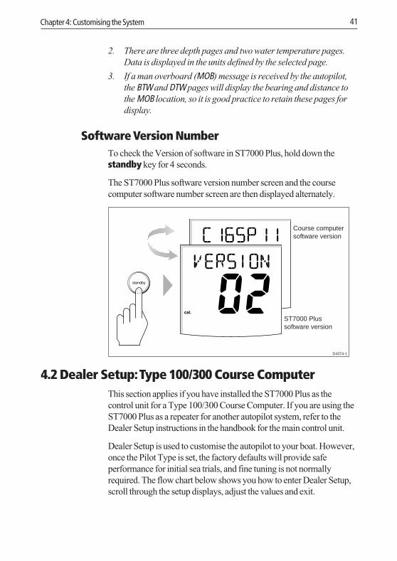
Software Version NumberTo check the Version of software in ST7000 Plus, hold down thestandby key for 4 seconds.
The ST7000 Plus software version number screen and the coursecomputer software number screen are then displayed alternately.
Course computersoftware version
ST7000 Plussoftware version
D4374-1
4.2 Dealer Setup: Type 100/300 Course ComputerThis section applies if you have installed the ST7000 Plus as thecontrol unit for a Type 100/300 Course Computer. If you are using theST7000 Plus as a repeater for another autopilot system, refer to theDealer Setup instructions in the handbook for the main control unit.
Dealer Setup is used to customise the autopilot to your boat. However,once the Pilot Type is set, the factory defaults will provide safeperformance for initial sea trials, and fine tuning is not normallyrequired. The flow chart below shows you how to enter Dealer Setup,scroll through the setup displays, adjust the values and exit.
118ch04.p65 07/01/99, 12:4241

42 ST7000 Plus Autopilot Control Unit Owner’s Handbook
Recommended SettingsThis section details the calibration settings for sailing/powerdisplacement and planing power vessels. Once you have set the PilotType, these will provide good performance for initial sea trials and canbe fine tuned later to optimise performance.
After initial calibration has been carried out, further adjustment can bemade at any time.
The adjustable features are listed in a table at the end of this section,Use this table to record your settings for future reference. Informationon the functions of the different settings is given in the remainder ofthis section.
The following points should be noted:
• Make sure that the autopilot is in Standby mode before you accessDealer Setup.
• Setup options are always automatically saved on exit.
Pilot TypeThis should be set when the system is first switched on. The defaultsettings for other Dealer Setup options depend on the pilot type youselect here.
118ch04.p65 07/01/99, 12:4242

Chapter 4: Customising the System 43
Setting Description
DISPLACE Displacement
SEMI/ DISPLACE Semi-displacement
PLANING Planing
STERN DRV Sterndrive
Default: DISPLACE
Calibration LockCalibration lock controls the access to User Setup, and is intended forcharter boat users.
Setting Description
ON User setup locked
OFF User setup unlocked
Default: OFF
Rudder GainThis must be set while under way, as described in Chapter 6, PostInstallation Procedures.
Range: 1 to 9
Default: for Pilot Type Displacement 5for Pilot Type Semi-Displacement 5for Pilot Type Planing 4for Pilot Type Stern drive 3
Rate LevelRate Level applies rudder to reduce the rate of change of course. If thevessel is turning at too fast a rate, the rate level will counter this turnwith opposite rudder.
118ch04.p65 07/01/99, 12:4243

44 ST7000 Plus Autopilot Control Unit Owner’s Handbook
The settings available are as follows:
Range: 1 to 9
Default: for Pilot Type Displacement 7for Pilot Type Semi-Displacement 7for Pilot Type Planing 7for Pilot Type Stern drive 5
Rudder OffsetYou only need to set this option if your system includes a rudderreference unit.
• Manually place the helm in a central position. The reported rudderangle is indicated on the rudder bar graphic at the bottom of thescreen.
• Adjust the offset value, using the +1 and -1 keys, until the rudderposition is shown as central on the rudder bar. The offset must bewithin the range -7° to +7°.
Range: –7° to +7°
Default: 0°
Rudder LimitRudder Limit restricts autopilot rudder movement to just less than thesteering systems mechanical stops. This avoids putting the steeringsystem under unnecessary load.
Range: 15° to 40°
Default: for Pilot Type Displacement 30°for Pilot Type Semi-Displacement 30°for Pilot Type Planing 30°for Pilot Type Stern drive 20°
Turn LimitThis limits the rate of turn of your vessel when making a course changeunder autopilot control. The value must be within the range 5 to 20°.For sailboat applications it should be set to 20°.
118ch04.p65 07/01/99, 12:4244

Chapter 4: Customising the System 45
Range: 5° to 20°/second
Default: for Pilot Type Displacement 20°/secondfor Pilot Type Semi-Displacement 15°/secondfor Pilot Type Planing 15°/secondfor Pilot Type Stern drive 08°/second
Cruise SpeedCruise speed should be set to the boat’s normal cruising speed if boatspeed is not available via SeaTalk or NMEA – SeaTalk boat speed isused in preference to SOG.
Range: 4 to 60 knots
Default: for Pilot Type Displacement 6for Pilot Type Semi-Displacement 8for Pilot Type Planing 15for Pilot Type Sterndrive 15
Off Course AlarmThis feature controls the alarm that warns you if the pilot is unable tomaintain its set course. The alarm operates if the autopilot strays offcourse by more than the alarm angle limit for more than 20 seconds.
The value must be within the range 15 to 40°, and can be adjusted in 1°steps.
Range: 15 to 40°
Default: 20°
118ch04.p65 07/01/99, 12:4245
46 ST7000 Plus Autopilot Control Unit Owner’s Handbook
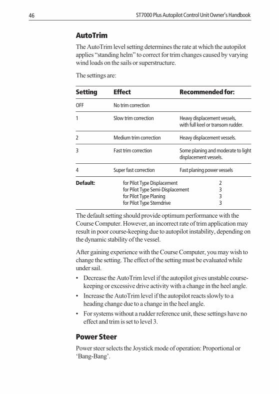
AutoTrimThe AutoTrim level setting determines the rate at which the autopilotapplies “standing helm” to correct for trim changes caused by varyingwind loads on the sails or superstructure.
The settings are:
Setting Effect Recommended for:
OFF No trim correction
1 Slow trim correction Heavy displacement vessels,with full keel or transom rudder.
2 Medium trim correction Heavy displacement vessels.
3 Fast trim correction Some planing and moderate to lightdisplacement vessels.
4 Super fast correction Fast planing power vessels
Default: for Pilot Type Displacement 2for Pilot Type Semi-Displacement 3for Pilot Type Planing 3for Pilot Type Sterndrive 3
The default setting should provide optimum performance with theCourse Computer. However, an incorrect rate of trim application mayresult in poor course-keeping due to autopilot instability, depending onthe dynamic stability of the vessel.
After gaining experience with the Course Computer, you may wish tochange the setting. The effect of the setting must be evaluated whileunder sail.
• Decrease the AutoTrim level if the autopilot gives unstable course-keeping or excessive drive activity with a change in the heel angle.
• Increase the AutoTrim level if the autopilot reacts slowly to aheading change due to a change in the heel angle.
• For systems without a rudder reference unit, these settings have noeffect and trim is set to level 3.
Power SteerPower steer selects the Joystick mode of operation: Proportional or‘Bang-Bang’.
118ch04.p65 07/01/99, 12:4246

Chapter 4: Customising the System 47
Proportional applies rudder in proportion to Joystick movement - thefurther the Joystick is held over the greater the applied rudder.
Bang-Bang applies continuous rudder drive in the direction of levermovement. To improve control the speed of rudder movementchanges with the angle of the lever. For maximum speed push the leverhard over. If the lever is returned to the centre position the rudder willremain in its current position.
Range: OFF1 = Proportional2 = Bang-bang
Default: OFF
Drive TypeThe drive type controls the way which the autopilot drives the steeringsystem. The default setting should be retained for mechanically drivenvessels.
Range: 1 = Mechanically driven vessels without a rudder reference unit2 = Hydraulic, no rudder reference unit3 = Linear, rotary and sterndrive with a rudder reference unit4 = Hydraulic with rudder reference unit
Default: for Pilot Type Displacement 3for Pilot Type Semi-Displacement 4for Pilot Type Planing 4for Pilot Type Sterndrive 3
Rudder DampingSet this option only if your system includes a rudder reference unit, andthe drive hunts when trying to position the rudder.
Test for this when your vessel is moored dockside, by pressing AUTOand then +10. If the helm overshoots and has to drive back, or starts tohunt back and forth, increase the damping level.
Alternatively, you can set a value between 1 to 9. Adjust the dampingone level at a time, and always use the lowest acceptable value.
Range: 1 to 9
Default: 2
118ch04.p65 07/01/99, 12:4247

48 ST7000 Plus Autopilot Control Unit Owner’s Handbook
VariationIf required, set this value to the level of magnetic variation present atyour vessel’s current position. The variation setting is sent to otherinstruments on the SeaTalk system, and can be updated by otherSeaTalk instruments.
Range: 30° EAST or WEST
Default: 0°
AutoAdapt
The AutoAdapt feature allows the Course Computer to compensate forheading errors at higher latitudes, which are caused by the increasingdip of the earth’s magnetic field. The increased dip has the effect ofamplifying rudder response on northerly headings in the northernhemisphere, and on southerly headings in the southern hemisphere.
Set AutoAdapt to nth in the northern hemisphere, or Sth in the southernhemisphere. You then need to enter your current latitude in the nextsetup screen, so that the Course Computer can provide accuratecourse-keeping by automatically adjusting the rudder gain dependingon the heading.
Range: OFFnth = NorthSth = South
Default: OFF
118ch04.p65 07/01/99, 12:4248

Chapter 4: Customising the System 49
LatitudeThis screen is only used if AutoAdapt is set to North or South.
Use the up and down arrow keys to set the value to your vessel’scurrent latitude, to the nearest degree.
Range: 0° to 80°
Default: 0°
Note: If valid latitude data is available via SeaTalk or NMEA, it will beused instead of this calibration value.
Wind TrimThis varies the response of the autopilot when in Wind mode.
Range: 1 = Normal setting2 = Faster response for wind shifts
Default: 1
AutoReleaseAutoRelease provides emergency manual override, should it benecessary, to avoid an obstacle at the last moment. This option onlyapplies to cable-operated sterndrive actuators – for all other systemsthis option should be set to off.
Range: OFFOn
Default: for Pilot Type Displacement OFFfor Pilot Type Semi-Displacement OFFfor Pilot Type Planing OFFfor Pilot Type Sterndrive On
ResponseThis is the power-on response setting. The response level can bechanged during normal operation (see Section 3.3).
Range: 1 = Auto Seastate2 = Auto sea state inhibit3 = Auto sea state inhibit with counter rudder
Default: 1
118ch04.p65 07/01/99, 12:4249

50 ST7000 Plus Autopilot Control Unit Owner’s Handbook
Recording Calibration SettingsHaving fine-tuned the calibration settings during initial sea trials,record them in the following table for future reference.
Feature Setting
Pilot Type
Calibration Lock
Rudder gain
Response
Turn rate Limit
Rudder Offset
Off Course Alarm
AutoTrim
Drive Type
Variation
AutoAdapt
Latitude
Rudder Damping
AutoRelease
Cruise Speed
Power Speed
Rudder Limit
Rate Level
4.3 Setting Up For ST60 and ST80 Remote ControlWhere the ST7000 Plus is used in conjunction with ST60 or ST80instrumentation, the ST7000 Plus can be used to control the ST60or ST80 instruments by duplicating the functions of the Remote
118ch04.p65 07/01/99, 12:4250

Chapter 4: Customising the System 51
Keypads used by these instruments, to allow you to operate yourautopilot and ST60/ST80 instruments from the same location.
Instrument GroupingControl of ST60 and ST80 instruments is achieved by allocatinggroups of instruments to Remote Control Keypads (in this case, theST7000 Plus is used as one such keypad). The ST7000 Plus uses INSTREM and MAXI REM Data Pages, to control standard (110 mm) andMaxiview instrument groups, respectively. Each ST7000 Plus cancontrol one group of up to eight ST60 or ST80 standard instrumentsand another group of up to eight ST80 Maxiview instruments.
Before an ST7000 Plus can be used to remotely control otherinstruments, you must first define the instrument grouping and thenallocate the ST7000 Plus to the required group.
Setting Up GroupsGrouping allows you to create up to eight standard instrument andeight Maxiview instrument groups:
• Each group can have up to eight instruments.
• Each group must have one or more Remote Keypads or an ST7000Plus grouped to it.
• Each ST7000 Plus can be grouped with one Maxiview group andone standard instrument group.
• Each instrument in a group has a unique alphanumeric identity (e.g.A1, where A defines the group and 1 the instrument sequencenumber within the group). Standard ST60 or ST80 instruments areassigned group letters from A to H. Maxiview instruments areassigned group letters from J to Q. Ungrouped instruments have adash (-) in place of a group letter.
• The instrument sequence number range is from 1 to 8.
For the purposes of conciseness, the ST7000 Plus keys used to controlgroups of ST60 or ST80 instruments are referred to in this handbook asthe instrument group keys. The instrument group keys are:
• For standard instruments, resp, track, set crs, res’m, down arrowand up arrow.
• For Maxiview instruments, resp, track, down arrow and up arrow.
118ch04.p65 07/01/99, 12:4251

52 ST7000 Plus Autopilot Control Unit Owner’s Handbook
Grouping Standard InstrumentsThe instrument group key functions for setting up ST60 and ST80standard instrument groups are shown in the following illustration.
When setting up an instrument group, you need to understand theindications which show when an instrument is selected. This dependson instrument type as follows:
• On selected ST80 instruments, the characters are displayed ininverse video (i.e. white characters on a black background).
• On selected ST60 digital instruments, a REMOTE legend isdisplayed.
• On selected ST60 analogue instruments, either one or both of theTRUE/MAG or TRUE/APP annunciators flash on the digital display.
To set up a standard instrument group:
1. At the ST7000 Plus, select the INST REM Data Page.
2. Press one of the instrument group keys so that one of the ST60 orST80 instruments is selected.
3. Hold down the up and down arrow keys for 4 seconds, to put all
118ch04.p65 07/01/99, 12:4352

Chapter 4: Customising the System 53
the standard instruments and the ST7000 Plus into group setupmode. When this occurs, one standard instrument is selected witha flashing cursor, and the ST7000 Plus screen text will alternatebetween INST REM and DSP SETUP.
4. At the ST7000 Plus, use the up arrow or down arrow key to selectan instrument to be the first in the group.
5. Use the ST7000 Plus to allocate a group letter and sequencenumber to the selected instrument. To do this, use the track key totoggle between group letter and sequence number, and the set crskey to set the identifying character. When the instrument has beenproperly identified it should display its group letter and sequencenumber, e.g. A2.
Note: All standard instruments are selectable while in group setupmode.
6. Press either the up arrow or down arrow key to select anotherinstrument and repeat the procedure in step 5.
7. Repeat the procedures in steps 5. and 6. until all instruments in thegroup have been identified.
Note: If you have more than eight ST60 or ST80 instruments, a secondgroup, operated by another remote keypad, must be created. Theidentification code for additional keypads and display heads would befor example, B1, B2 etc.
8. Use the arrow keys to select one of the ST60 or ST80 instrumentsin the group to which you want to allocate the ST7000 Plus as akeypad.
9. Hold down the up and down arrow keys together for 1 second.The ST7000 Plus screen text will alternate between INST REM andKPD SETUP, and each of the instruments in the selected group willdisplay prompt messages similar to the following.
118ch04.p65 07/01/99, 12:4353

54 ST7000 Plus Autopilot Control Unit Owner’s Handbook
10. Press one of the instrument group keys on the ST7000 Plus toallocate it to the selected group of instruments.
11. If you are creating more than one group, repeat the proceduresdescribed in actions 3 to 10.
12. When all instrument groups have been set up, hold down thetrack and set crs keys for 1 second, to return to group setupmode.
13. Hold down the track and set crs keys for 2 seconds, to return tonormal operation.
Grouping Maxiview InstrumentsThe instrument group key functions for setting up Maxiviewinstrument groups are as follows:
Select the required Maxiview instrument
118ch04.p65 07/01/99, 12:4354

Chapter 4: Customising the System 55
To set up a Maxiview instrument group:
1. At the ST7000 Plus, select the MAXI REM Data Page.
2. Press one of the instrument group keys so that one of theMaxiview instruments is selected (indicated by inverse displaycharacters on the selected instrument).
3. Hold down the up and down arrow keys for 4 seconds, to put allthe Maxiview instruments and the ST7000 Plus into group setupmode. When this occurs, one Maxiview instrument displaysreverse video with a flashing cursor, and the ST7000 Plus screentext will alternate between MAXI REM and DSP SETUP.
4. At the ST7000 Plus, use the up arrow or down arrow key to selectan instrument to be the first in the group, i.e. so the requiredinstrument changes to inverse video.
5. Use the ST7000 Plus to allocate a group letter and sequencenumber to the selected Maxiview. To do this, use the resp key totoggle between group letter and sequence number, and the trackkey to set the identifying character. When the Maxiviewinstrument has been properly identified it should display its groupletter and sequence number, e.g. J2.
Note: All Maxiview instruments are selectable while in group setupmode.
6. Press either the up arrow or down arrow key to select anotherMaxiview instrument, and repeat the procedure in step 5.
7. Repeat the procedures in steps 5. and 6. until all instruments in thegroup have been identified.
Note: If you have more than eight Maxiview instruments, a secondgroup, operated by another remote keypad, must be created. Theidentification code for additional keypads and display heads would befor example, K1, K2 etc.
8. Use the arrow keys to select one of the Maxiview instruments inthe group to which you want to allocate the ST7000 Plus as akeypad.
9. Hold down the up and down arrow keys together for 1 second.The ST7000 Plus screen text will alternate between MAXI REM andKPD SETUP, and each of the Maxiview instruments in the selectedgroup will display prompt messages similar to those for thestandard instrument.
118ch04.p65 07/01/99, 12:4355

56 ST7000 Plus Autopilot Control Unit Owner’s Handbook
10. Press one of the instrument group keys on the ST7000 Plus toallocate it to the selected group of display heads.
11. If you are creating more than one group, repeat the proceduresdescribed in actions 3 to 10.
12. When all instrument groups have been set up, hold down the respand track keys for 1 second, to return to group setup mode.
13. Hold down the resp and track keys for 2 seconds, to return tonormal operation.
118ch04.p65 07/01/99, 12:4356

Chapter 5: Installation 57
Chapter 5: Installation5.1 Planning the Installation
This chapter explains how to install and connect the ST7000 Plusautopilot control unit. Before starting the installation, decide how youwill site the unit and run the cables.
EMC Installation GuidelinesThe design and manufacture of Raytheon equipment and accessoriesconforms to the appropriate Electromagnetic Compatibility (EMC)standards, but good installation is required to ensure that performanceis not compromised.
To avoid the risk of operating problems, all Raytheon equipment andcables connected to it should be:
• At least 1 m from any equipment transmitting or cables carryingradio signals e.g. VHF radios, cables and antennas. In the case ofSSB radios, the distance should be increased to 2 m.
• More than 2 m from the path of a radar beam. A radar beam cannormally be assumed to spread 20° above and below the radiatingelement.
• The equipment should be supplied from a different battery than theone used for engine start. Voltage drops below 10 V in the powersupply to our products can cause the equipment to reset. This willnot damage the equipment, but will cause the loss of someinformation and can change the operating mode.
• Genuine Raytheon cables should be used at all times. Cutting andrejoining these cables can compromise EMC performance and soshould be avoided unless called for in the installation manual.
• If a suppression ferrite is attached to a cable, this ferrite should notbe removed. If the ferrite has to be removed to facilitate installationit must be reassembled in the same position.
If your Raytheon equipment is going to be connected to otherequipment using a cable not supplied by Raytheon, a suppressionferrite MUST always be fitted to the cable close to the Raytheon unit.
The following illustration shows the range of suppression ferrites fittedto Raytheon equipment.
118ch05.p65 07/01/99, 12:4357

58 ST7000 Plus Autopilot Control Unit Owner’s Handbook
Cabling• Avoid running cables through bilges where possible.
• Secure coiled lengths at regular intervals.
• Avoid running cables close to fluorescent lights, engines, radiotransmitting equipment etc.
5.2 Instrument
Siting
CAUTIONThe instrument must be installed so that the rear case is protectedfrom water. The presence of moisture could cause damage eitherby entering the instrument through the breathing hole or bycoming into contact with the electrical connectors at the rear.
118ch05.p65 07/01/99, 12:4358

Chapter 5: Installation 59
The instrument can be installed either above or below deck, providedthe rear of the instrument is sited where it is protected from contactwith water.
The instrument must also be positioned where it is:
• Within easy reach of the steering position.
• Protected from physical damage.
• At least 230 mm from any compass.
• At least 500 mm from any radio/radar receiving/transmittingequipment.
Mounting Procedure
2 31
1 Cable boss 2 Fixing studs 3 Thumb nuts
Note: Always leave a 6 mm gap between adjacent display heads toallow the protective sun covers to be fitted.
1. Use the template provided (after the Index in this handbook) tomark the hole centres for the fixing stud and the cable boss.
2. Drill four 5 mm diameter holes for the fixing studs.
3. Taking great care not to cut the hole for the cable boss too big,use a 90 mm diameter cutter to drill the hole for the cable boss (1).
118ch05.p65 07/01/99, 12:4359

60 ST7000 Plus Autopilot Control Unit Owner’s Handbook
4. Screw the fixing studs (2) into the display head.
5. Pass the cables (SeaTalk, NMEA) through the bulkhead.
6. Fit the cables to the appropriate terminals (see relevant subsectionfor connection details of each item).
7. Fit the display head to the bulkhead.
8. Assemble the thumb nuts (3) onto the fixing studs (2).
9. Tighten the thumb nuts by hand until the display head is secure.Under no circumstances must a wrench be used to tighten thethumb nuts.
PowerPower to the ST7000 Plus should be supplied by the associatedautopilot, in accordance with the instructions in the relevant autopilothandbook.
Connections to the SeaTalk Bus
SeaTalk CablesThe ST7000 Plus is supplied with a 9 m SeaTalk cable as standard.The following table lists other cables available from your dealer:
Part No: Type Length
D187 Flat to a male round connector 0.15 m
D188 Flat to a female round connector 0.3 m
D284 Flat moulded plugs at both ends 1 m
D285 Flat moulded plugs at both ends 3 m
D286 Flat moulded plugs at both ends 6 m
D287 Flat moulded plugs at both ends 9 m
Cable TypesThe following illustration shows the different types of SeaTalk cablesavailable.
118ch05.p65 07/01/99, 12:4360

Chapter 5: Installation 61
D3445-1
Typical SeaTalk Cabling
5.3 NMEA InterfaceST7000 Plus accepts NMEA navigation data for display and use inTrack and Wind modes. The required NMEA data formats are shownin the table at the end of this section.
CablingThe NMEA port should be connected to a Navigator or Windinstrument.
118ch05.p65 07/01/99, 12:4361

62 ST7000 Plus Autopilot Control Unit Owner’s Handbook
Red(Data In +ve)
Blue(Data In -ve)
D3442-1
Navigatorwith NMEA output
NMEA Cable Connectors• NMEA connections are made using spade connectors.
• When fitting the spade connectors, make sure the connector fitssecurely over the blade and not between the connector and itsplastic insulating boot. Incorrectly fitted connectors will giveintermittent contact and result in faulty control unit operation.
NMEA DataThe following NMEA 0183 wind and navigation data can be decodedby the ST7000 Plus.
118ch05.p65 07/01/99, 12:4362

Chapter 5: Installation 63
Data NMEA 0183
Latitude and Longitude GLL, RMC, RMA, GLP, GOP, GXP, GGA,GDP
Course Over Ground VTG, RMC, RMA
Speed Over Ground VTG, RMC, RMA
Cross Track Error APB, APA, RMB, XTE
Bearing to Waypoint APB, BWR, BWC, RMB
Distance to Waypoint BWR, BWC, RMB
Waypoint Number APB, APA, BWR, BWC, RMB
Apparent Wind Speed VWR, MWV
Apparent Wind Angle VWR, MWV
Speed Through Water VHW
Depth DBT
Water Temperature MTW
Transmission of NMEA Data on SeaTalkIf any of the above NMEA data is received and the equivalent data isnot present on SeaTalk, the ST7000 Plus will transmit the data ontoSeaTalk to make it available to other SeaTalk compatible instruments.
Depth is transmitted in the units defined by the first depth page in thedata page rollover. Water temperature is always transmitted in ºC.
If you wish to transmit NMEA information to other equipment aSeaTalk-to-NMEA bridge should be installed.
5.4 Functional Test (Repeater Unit)If you have installed your ST7000 Plus as a repeater unit on anautopilot system, you should perform the functional test described inthis section. However, if you have installed the ST7000 Plus as theonly control unit for a Type 100/300 course computer, you should nowcarry out the procedures in Chapter 6, Post Installation Procedures.
118ch05.p65 07/01/99, 12:4363

64 ST7000 Plus Autopilot Control Unit Owner’s Handbook
Switch OnHaving installed your ST7000 Plus, switch on the main power breaker.If the instrument is active and the system is operating, the followingwill occur:
• The instrument beeps and displays the control unit type, ST7000+.
• After the control unit type has been displayed for 2 seconds, theStandby mode screen should be displayed.
D4236-1
This shows that the control head is active. If the above events do notoccur, check the fuse/circuit breaker.
If the text SEATALK FAILURE or NO LINK is displayed, check the SeaTalkcables between the ST7000 Plus control head and the CourseComputer.
Navigation Interface (GPS, Decca, Loran)If the ST7000 Plus is interfaced to a navigator, via its NMEA data port,the interface can be checked by displaying the default Data Pages.These are XTE, BTW and DTW.
Press disp to display the first page, and check that the expected data isdisplayed. Press disp again to check each successive page.
If dashes are displayed instead of data values, the cause could be one ormore of the following:
• A cabling error. Check for an open circuit, short circuit or reversedwires.
• The navigator is not configured to transmit the required data format.
• The signals being received by the navigator are too weak forreliable navigation. Refer to the navigator handbook for furtheraction.
118ch05.p65 07/01/99, 12:4364

Chapter 5: Installation 65
SeaTalk InterfaceIf the ST7000 Plus has been linked to other instruments via SeaTalk,the link can be checked as follows:
1. Press standby.
2. Select display illumination level 3 on any other SeaTalkinstrument or autopilot control unit.
The ST7000 Plus should immediately respond by switching on itsdisplay illumination.
If the illumination does not switch on then a cabling fault exists in theSeaTalk cabling between the ST7000 Plus control unit and theinstruments/control unit.
118ch05.p65 07/01/99, 12:4365

66 ST7000 Plus Autopilot Control Unit Owner’s Handbook
118ch05.p65 07/01/99, 12:4366

Chapter 6: Post Installation Procedures 67
Chapter 6: Post Installation ProceduresThis chapter applies to systems where the ST7000 Plus has beeninstalled as the only control unit for a Type 100/300 Course Computer.
Once you have installed the system, you need to confirm that it is wiredcorrectly and is also set up to suit your type of boat.
This chapter provides instructions for the following procedures:
• Functional test, consisting of a few simple tests to confirm that thesystem is wired correctly.
• Initial sea trial, to swing the compass and align the heading, checkthe autopilot’s operation and check the rudder gain.
Further customisation can be performed after the sea trial, as describedin Chapter 4.
6.1 Functional Test and Initial Calibration
Switch OnHaving installed your ST7000 Plus system, switch on the main powerbreaker. If the instrument is active and the system operating, thefollowing will occur:
• The instrument beeps and displays ST7000+.
• If either the Pilot Type has not been set, or compass linearisation orcompass alignment have not been carried out, then the display willflash between CALIBRATE and REQUIRED, for approximately4 seconds, after which time the STANDBY screen is displayed.
• In all other cases, the STANDBY screen is displayed 2 seconds afterthe ST7000+ screen.
This shows that the instrument is active.
• If the instrument does not beep or the display is blank, check thefuse/circuit breaker.
• If the SEATALK FAILURE or NO LINK alarm is displayed, check theSeaTalk connections.
Initial CalibrationSet up the correct Pilot Type as described in Chapter 4.
118ch06.p65 07/01/99, 12:4367

68 ST7000 Plus Autopilot Control Unit Owner’s Handbook
Operating SenseThe operating sense defines the direction the helm will be appliedwhen a course change key is pressed or the vessel goes off course.Check the operating sense as follows:
1. In Standby mode, move the wheel to produce a starboard turn, andcheck that the rudder angle displaymoves to the right. If the rudderangle display moves to the left, the red and green wires from therudder reference transducer must be reversed.
2. Press auto.
3. Press the +10 key. The helm should move to produce a turn tostarboard.
4. If the helm produces a turn to port, reverse the motor connectionsat the course computer.
5. If the helm overshoots and has to drive back or starts to hunt backand forth, you need to increase the Rudder Damping, describedunder Dealer Setup in Chapter 4.
Navigation Interface (GPS, Decca, Loran)If the ST7000 Plus is interfaced to a navigator, via its NMEA data port,the interface can be checked by displaying the default Data Pages.These are XTE, BTW, and DTW.
Press disp to display the first page, and check that the expected data isdisplayed. Press disp again to check each successive page.
If dashes are displayed instead of data values, the cause could be one ormore of the following:
118ch06.p65 07/01/99, 12:4368

Chapter 6: Post Installation Procedures 69
• A cabling error. Check for an open circuit, short circuit or reversedwires.
• The navigator is not configured to transmit the required data format.
• The signals being received by the navigator are too weak forreliable navigation. Refer to the navigator handbook for furtheraction.
Wind Transducer InterfaceIf the ST7000 Plus is connected to a wind instrument via its NMEAdata port or SeaTalk, then the link between the two instruments shouldbe checked by pressing standby and auto together.
The ST7000 Plus should display the Wind mode screen, with thelocked wind angle and locked heading as shown.
SeaTalk InterfaceIf the ST7000 Plus has been linked to other SeaTalk instruments viaSeaTalk, the link can be checked as follows:
1. Press standby.
2. Select display illumination level 3 on any other SeaTalkinstrument or autopilot control unit.
118ch06.p65 07/01/99, 12:4369

70 ST7000 Plus Autopilot Control Unit Owner’s Handbook
The ST7000 Plus should immediately respond by switching on itsdisplay illumination.
If the illumination does not switch on then a cabling fault exists in theSeaTalk cabling between the ST7000 Plus control head and theinstruments/control unit.
EMC ConformanceThe design and manufacture of Autohelm equipment and accessoriesconforms to the appropriate Electromagnetic Compatibility (EMC)standards, but good installation is required to ensure that performanceis not compromised. Although every effort has been taken to ensurethat they will perform under all conditions, it is important tounderstand what factors could affect the operation of the product.
Always check the installation before going to sea to make sure that it isnot affected by radio transmissions, engine starting etc.
In some installations, it may not be possible to prevent the equipmentfrom being affected by external influences. In general this will notdamage the equipment but can lead to it resetting, or momentarily mayresult in faulty operation.
6.2 Initial Sea TrialHaving checked that the system is functioning correctly, a short seatrial is now required to complete the setup. It involves the followingprocedures:
• Automatic compass deviation correction.
• Heading alignment adjustment.
• Autopilot operation check.
• Rudder gain adjustment.
Note: The ST7000 Plus has a built-in calibration capability whichenables the autopilot to be fine tuned to suit the individual vessel, itssteering system and dynamic steering characteristics. As supplied fromthe factory the unit is calibrated to provide safe stable autopilot controlfor the majority of vessels.
The initial sea trial should be performed under the followingconditions:
• After all the successful completion of the installation procedure,functional testing and initial calibration.
118ch06.p65 07/01/99, 12:4470

Chapter 6: Post Installation Procedures 71
• Before any other changes have been made to the default calibrationsettings. Check and, if necessary, reset the values to therecommended levels, as described in Chapter 4.
• Light wind and calm water, so that autopilot performance can beassessed without the influence of strong winds or large waves.
• In waters clear of any obstructions.
Note: At any time during the sea trial you can press standby to returnto hand steering.
Automatic Compass Deviation CorrectionThe autopilot will correct the fluxgate compass for most deviatingmagnetic fields. Compass errors due to deviating magnetic fields canbe up to 45°, depending on your vessel type. The correction procedurereduces these to a few degrees, so it is essential to perform theprocedure as the first item in your initial sea trial.
CAUTIONFailure to carry out the deviation correction may result inimpaired autopilot performance on some compass headings.
To allow the system to determine the deviation and calculate anycorrection required, you must turn your vessel in slow circles. Thisprocedure must be carried out in calm conditions and preferably in flatwater.
To perform the deviation correction:
1. Make sure that the autopilot is in Standby mode.
2. Press and hold the standby key for 2 seconds to display the UserSetup entry page. If CAL LOCK is displayed, you need to turn off thelock feature contained in Dealer Setup (see Chapter 4).
118ch06.p65 07/01/99, 12:4471

72 ST7000 Plus Autopilot Control Unit Owner’s Handbook
3. Press the disp key to move on to the Swing Compass page.
4. Press the +1 or -1 key to change the setting from OFF to YES. TheTurn Boat page is then displayed.
5. Keeping the boat speed below 2 knots, turn the vessel in slowcircles. It should take at least 3 minutes to complete 360°.
6. Keep turning your boat until the unit beeps and the Deviationscreen is displayed.
118ch06.p65 07/01/99, 12:4472

Chapter 6: Post Installation Procedures 73
This shows the maximum deviation detected, and indicates thatcompass correction has been completed successfully.
Note: If the deviation value exceeds 15°, you should consider movingthe fluxgate compass to a better location.
7. Press the disp key to move on to the Heading Alignment page.
8. Use the +1,-1, +10 and -10 keys, to adjust the displayed heading,until it agrees with the ship’s steering compass or a known transitbearing.
9. Press and hold standby for 2 seconds to exit calibration and savethe new settings.
Note: Setup options are always saved on exit.
118ch06.p65 07/01/99, 12:4473

74 ST7000 Plus Autopilot Control Unit Owner’s Handbook
Further Heading Alignment AdjustmentYou should always check the compass alignment after swinging thecompass. However, once the initial deviation correction procedure hasbeen performed, you can make adjustments to the alignment as oftenas you wish, without swinging the compass again.
Although the compass deviation correction procedure removes mostof the alignment error, you will probably be left with a small error (ofthe order of a few degrees) that will vary depending on the heading.
Ideally, you should check the heading reading against a number ofknown headings, plot a deviation curve, and determine the headingalignment value that will give the lowest average alignment error.This value can then be entered on the Heading Alignment screen, asdescribed above.
If the average heading error is more than 5°, you should perform thecompass deviation correction procedure again.
Checking Autopilot OperationHaving calibrated the compass the following procedure isrecommended to familiarise yourself with autopilot operation:
1. Steer onto a compass heading and hold the course steady.
2. Press auto to lock onto the current heading. A constant headingshould be achieved in calm sea conditions.
3. Use the -1, -10, +1 and +10 keys to alter course to port orstarboard in multiples of 1° and 10°.
4. Press standby and disengage the autopilot to return to handsteering.
Checking the Rudder GainThe factory set rudder gain level will provide stable control for initialsea trials. However, vessels can vary widely in their response to thehelm, and further adjustment to the rudder gain may improve theautopilot’s steering characteristics.
It is particularly important that the rudder gain is set correctly on high-speed craft. Incorrect adjustment will lead to poor steeringperformance and is a dangerous condition at high speed.
118ch06.p65 07/01/99, 12:4474

Chapter 6: Post Installation Procedures 75
The following test will determine whether the rudder gain is set toohigh or too low:
1. In clear water and with the autopilot in Auto, alter course tostarboard by 40° by pressing the +10 key four times.
• At cruising speeds, course changes of 40° should result in crispturns followed by an overshoot of no more than 5°. If thisoccurs the rudder gain is adjusted correctly (as at A below).
• An excessively high rudder setting results in oversteer. This isrecognised by a distinct overshoot of more than 5° (as at Bbelow). This condition can be corrected by reducing the ruddergain setting.
• Similarly, an insufficient rudder control setting will result inundersteer which gives sluggish steering performance (as at Cbelow). If the vessel takes a long time to make the turn andthere is no overshoot then the rudder setting is too low.
D4234-1
These actions are most easily recognised in calm seaconditions where wave action does not mask basic steeringperformance.
2. Refer to Chapter 4, Customising the System, for instructions onhow to adjust the default rudder gain setting. Note that you canalso make temporary adjustments to rudder gain during normaloperation (see Adjusting Autopilot Performance in Chapter 2).
118ch06.p65 07/01/99, 12:4475

76 ST7000 Plus Autopilot Control Unit Owner’s Handbook
3. Repeat the test until a crisp course change with no more 5° ofovershoot is achieved.
The rudder control setting should be set to the lowest setting consistentwith accurate course keeping. This will minimise helm movementsand hence reduce power consumption and wear and tear.
118ch06.p65 07/01/99, 12:4476

Chapter 7: Maintenance 77
Chapter 7: Maintenance
General• In certain conditions, condensation may appear on the LCD
window. This will not harm the unit, and can be cleared byswitching on the illumination for a while.
• Never use chemical or abrasive materials to clean yourST7000 Plus. If it is dirty, wipe it with a clean, damp cloth.
• Periodically check the cabling for chafing or damage to the outercasing – replace any damaged cables.
Servicing and Safety• Autohelm equipment should be serviced only by authorised
Autohelm service engineers. They will ensure that serviceprocedures and replacement parts used will not affect performance.There are no user serviceable parts in any Autohelm product.
• Some products generate high voltages, and so never handle thecables/connectors when power is being supplied to the equipment.
• Always report any problem related to ElectromagneticCompatibility (EMC) to your nearest Autohelm dealer. We will useany such information to improve our quality standards.
Product SupportIf any difficulties arise with this product, please contact the AutohelmProduct Support department in the UK, or your own nationaldistributor who will be able to provide expert assistance.
The working parts of the drive system are sealed and lubricated for lifeduring manufacture – servicing is not required.
Before you consider returning the instrument, make sure that thepower supply cable is sound and that all connections are tight and freefrom corrosion. If the connections are secure, refer to the Fault Findingchapter of this handbook.
If a fault cannot be traced or rectified, please contact your nearestAutohelm dealer or Service Centre.
Always quote the product serial number, which is printed on the rearcover, and the software version number, which you can see bypressing standby for 4 seconds.
118ch07.p65 07/01/99, 12:4477

78 ST7000 Plus Autopilot Control Unit Owner’s Handbook
118ch07.p65 07/01/99, 12:4478

Chapter 8: Fault Finding 79
Chapter 8: Fault FindingAll Autohelm products are subjected to a comprehensive testprocedure prior to packing and shipping. In the unlikely event that afault does occur with your autopilot, the following check list shouldhelp identify the problem and provide a cure.
The autopilot display is blank• No power – check the fuse/circuit breaker.
The displayed compass heading does not agree with theships compass• The compass has not been corrected for deviation – carry out the
deviation and alignment procedures.
Vessel turns slowly and takes a long time to come on tocourse• Rudder gain too low.
Vessel overshoots when turning on to a new course
• Rudder gain too high.
The autopilot appears to be unstable in Track mode, or track-holding is slow• If tide speed exceeds 35% of boat speed, and boat speed is not
available via SeaTalk, change the Cruise Speed setting in DealerSetup to the boat’s cruising speed.
The autopilot appears to be unstable on Northerly headingsin the Northern hemisphere or Southerly headings in theSouthern hemisphere• Northerly/Southerly heading correction not set up.
Display shows CAL LOCK when entering calibration• Calibration locked out – calibration protection feature is turned on
in Dealer Setup.
The autopilot will not talk to other SeaTalk instruments (maybe indicated by a SEATALK FAILURE alarm )• Cabling problem – make sure all the cables are connected properly.
118ch08.p65 07/01/99, 12:4479

80 ST7000 Plus Autopilot Control Unit Owner’s Handbook
Position information not received• Navigator not transmitting the correct position data.
The autopilot will not auto advance to the next waypoint• No bearing to waypoint information received from the navigator.
A series of rotating dashes are displayed on screen• Compass deviation correction or dockside rudder calibration is
running.
The display shows a series of stationary dashes• Data is not being received – check the cabling.
The display shows NO DATA• The signals received from the navigator are too weak – refer to the
navigator handbook for further action.
118ch08.p65 07/01/99, 12:4480

Index 81
Index
A
AdjustingAutopilot performance 28Locked wind angle 25Response levels 28Rudder Gain 29
Advance 22Advanced Operation 17Alarms 29
AutoRelease 32Drive stopped 30Large XTE 30Low battery 31Man overboard (MOB) 33Next WPT 31No data 30No link 29Off course 30Route completed 32SeaTalk failure 29Shallow 33Watch 32Wind shift 30
Auto mode 5Course changes 10Dodging obstacles 7Major course changes 10
AutoAdapt 48Automatic acquisition 18Automatic deadband 28Automatic tack (AutoTack) 9Automatic track acquisition 18Autopilot performance adjustment 28AutoRelease 49
Alarm 32AutoSeastate 28AutoTack
In Wind mode 26To Port 9To Starboard 9
AutoTrim 46
118index.p65 07/01/99, 12:4481

82 ST7000 Plus Autopilot Control Unit Owner’s Handbook
B
Backlighting 12Bar graph 4Bar selection 38Basic operation 3
C
Cabling 58Checking condition 77
Calibration lock 43Cancelling a dodge manoeuvre 22Checking autopilot operation 74Checking rudder gain 74Cleaning 77Compass
Alignment 73Deviation correction 71Deviation correction requirement 37
Condensation 77Connections to the SeaTalk bus 60Contrast adjustment 13Course change keys 6Course changes under autopilot control 10Cross track error (XTE) 20Cruise speed 45, 49Customising the autopilot 35–56
D
Data not received 30Data Pages 13, 39
Setting up 39Deadband 28Dealer setup 41, 41–56Deviation 72Deviation display 37Display 4Display contrast 13Dodges 22, 26Dodging obstacles
Auto mode 7Track mode 22Wind mode 26
Drive Stopped alarm 30Drive type 47
118index.p65 07/01/99, 12:4482

Index 83
E
EMCConformance xiii, 70Installation guidelines 57
Engaging the autopilot 5
F
Fault finding 79Front Panel 3Functional test as Repeater Unit 63
G
Graph use 38
H
Hand steering 6Heading alignment 37
Checking after compass swing 74Heading bar 4Heading mode 38
I
Initial calibration 67Initiating a dodge manoeuvre 22Initiating Track mode 17Installation 57Interfaces 64
J
Joystick control 11
K
Key functions 3
L
Large Cross Track Error 30Alarm 20
Last heading 8Latitude 49Locked wind angle 25Low battery alarm 31
118index.p65 07/01/99, 12:4483

84 ST7000 Plus Autopilot Control Unit Owner’s Handbook
M
Magnetic variation 48Maintenance 77Major course changes 10Man Overboard (MOB) alarm 33Manual acquisition 19Manual mode 11Manual steering 6Manual track acquisition 19Minimum deadband 28
N
Navigation data displays 13Navigation interface (GPS, Decca, Loran) 64, 68NEXT WPT 31NMEA
Cable Connectors 62Data Transmission 62Interface 61
No Data alarm 30No Link alarm 29
O
Off Course alarm 10, 30, 45clearing 30
Operating modes 1Operating sense 68Operation in Wind mode 24
P
Performance 28Pilot type 42Planning the installation 57Plot frequency 23Position confirmation at the start of a passage 23Post installation procedures 67Power requirement 2Power steer 46Previous apparent wind angle 25Previous heading 8Product support 77
118index.p65 07/01/99, 12:4484
Index 85
R
Recommended Settings 42Recording calibration settings 50Response levels 49
Adjusting 28Returning to the previous locked heading 8Route completed alarm 32Rudder bar 38Rudder calibration 38Rudder damping 47Rudder gain 29, 43, 74Rudder limit 44
S
Safety xii, 5, 23, 77Sea trial 70SeaTalk interface 65, 69
Data displays 13Failure 29Typical cabling 61
Servicing 77Set Course screen 6Setting waypoints 23Shallow alarm 33Skipping a waypoint 22Software version number 41ST60 and ST80 instruments
Controlling with ST7000 Plus 15Setting up for use with ST7000 Plus 50
Standby mode 6Start up conditions 5Steering bar 38Swinging the compass 71Switch on 67System testing 67–76
T
Testing the system 63, 67–76Tidal stream compensation 21Track acquisition 17Track mode 17–18Turn limit 44Turn rate level 43
118index.p65 07/01/99, 12:4485

86 ST7000 Plus Autopilot Control Unit Owner’s Handbook
U
User setup 35
V
Variation 48Verifying computed positions 23
W
Warranty xiWatch alarm 31Waypoints
Arrival and advance 21Setting 23Skipping 22Waypoint names 14
Wind angle error bar 4Wind mode 24Wind shift alarm 26, 30Wind transducer interface 69WindTrim 24, 49
118index.p65 07/01/99, 12:4486

Machine hole90mm diameter
Drill 5mm Drill 5mm
Drill 5mmDrill 5mm
D4235-1
118templ.p65
07/01/99, 12:441

118templ.p65 07/01/99, 12:442

Limited Warranty CertificateRaytheon Marine Company warrants each new Light Marine/Dealer Distributor Product to be of goodmaterials and workmanship, and will repair or exchange any parts proven to be defective in material andworkmanship under normal use for a period of 2 years/24 months from date of sale to end user, except asprovided below.
Defects will be corrected by Raytheon Marine Company or an authorized Raytheon dealer. Raytheon MarineCompany will, except as provided below, accept labor cost for a period of 2 years/24 months from the date ofsale to end user. During this period, except for certain products, travel costs (auto mileage and tolls) up to 100round trip highway miles and travel time of 2 hours, will be assumed by Raytheon Marine Company only onproducts where proof of installation or commission by authorised service agents, can be shown.
Warranty LimitationsRaytheon Marine Company Warranty policy does not apply to equipment which has been subjected toaccident, abuse or misuse, shipping damage, alterations, corrosion, incorrect and/or non-authorized service, orequipment on which the serial number has been altered, mutilated or removed.
Except where Raytheon Marine Company or its authorized dealer has performed the installation, it assumes noresponsibility for damage incurred during installation.
This Warranty does not cover routine system checkouts or alignment/calibration, unless required byreplacement of part(s) in the area being aligned.
A suitable proof of purchase, showing date, place, and serial number must be made available to RaytheonMarine Company or authorized service agent at the time of request for Warranty service.
Consumable items, (such as: Chart paper, lamps, fuses, batteries, styli, stylus/drive belts, radar mixer crystals/diodes, snap-in impeller carriers, impellers, impeller bearings, and impeller shaft) are specifically excludedfrom this Warranty.
Magnetrons, Cathode Ray Tubes (CRT), hailer horns and transducers are warranted for 1 year/12 months fromdate of sale. These items must be returned to a Raytheon Marine Company facility.
All costs associated with transducer replacement, other than the cost of the transducer itself, are specificallyexcluded from this Warranty.
Overtime premium labor portion of services outside of normal working hours is not covered by this Warranty.
Travel cost allowance on certain products with a suggested retail price below $2500.00 is not authorized.When/or if repairs are necessary, these products must be forwarded to a Raytheon Marine Company facility oran authorized dealer at owner’s expense will be returned via surface carrier at no cost to the owner.
Travel costs other than auto mileage, tolls and two (2) hours travel time, are specifically excluded on allproducts. Travel costs which are excluded from the coverage of this Warranty include but are not limited to:taxi, launch fees, aircraft rental, subsistence, customs, shipping and communication charges etc..
Travel costs, mileage and time, in excess to that allowed must have prior approval in writing.
TO THE EXTENT CONSISTENT WITH STATE AND FEDERAL LAW:
(1) THIS WARRANTY IS STRICTLY LIMITED TO THE TERMS INDICATED HEREIN, AND NOOTHER WARRANTIES OR REMEDIES SHALL BE BINDING ON RAYTHEON MARINE COMPANYINCLUDING WITHOUT LIMITATION ANY WARRANTIES OF MERCHANTABLE OR FITNESSFOR A PARTICULAR PURPOSE.
(2) Raytheon Marine Company shall not be liable for any incidental, consequential or special (includingpunitive or multiple) damages.
All Raytheon Marine Company products sold or provided hereunder are merely aids to navigation. It is theresponsibility of the user to exercise discretion and proper navigational skill independent of any Raytheonequipment. 44592_3
21st October 1998
118warry.p65 07/01/99, 12:443

Purchased from Purchase date
Dealer Address
Installed by Installation date
Commissioned by
Owner’s name
Mailing address
Factory Service CentersUnited States of AmericaRaytheon Marine CompanyAddress as above.
UK, Europe, Middle East, Far EastRaytheon Marine CompanyAddress as above.
United States of AmericaRaytheon Marine CompanyRecreational Products Tel 603-647-7530676 Island Pond Road Fax 603-634-4756Manchester, NH 03109-5420U.S.A.
UK, Europe, Middle East, Far EastRaytheon Marine CompanyRecreational Products Tel (44) 1705 693611Anchorage Park, Portsmouth Fax (44) 1705 694642PO3 5TD, England Fax Customer support (44) 1705 661228
Commissioning date
Stick barcode label here
This portion of card should be completed and retained by the owner.
118warry.p65 07/01/99, 12:444

Attn: Warranty DepartmentRaytheon Marine CompanyRecreational Products676 Island Pond RoadManchester NH 03109-9953USA
BUSINESS REPLY MAILFIRST CLASS MAIL PERMIT NO. 369 MANCHESTER NH
POSTAGE WILL BE PAID BY ADDRESSEE
NO POSTAGENECESSARY IF MAILED
IN THEUNITED STATES
118warry.p65
07/01/99, 12:445

Purchased from
Dealer address
Installed byInstallation date
Owner’s nam
e
Mailing address
North and South A
merica
Detach and mail this portion w
ithin 48 hours.
To validate the warranty, the custom
er or dealer must fill in
the requested information below
and mail to address show
non front.
Retain other portion for your records.
Comm
issioned by
Boat’s name/type/location
Comm
issioning date
Purchase date
Stick barcode label here
Owner’s occupation
118warry.p65 07/01/99, 12:446

Raytheon Marine CompanyRecreational ProductsFreepost PT 1127PortsmouthPO3 5BREngland
Note: This information is held by Raytheon Marine only and shall not be made available to any other companies. Raytheon Marine may send you mailshots/details of any new products.
Please tick this box ❐ if you do not wish to receive any further information from Raytheon Marine.
NO STAMP REQUIRED IF POSTED IN THE UK.
118warry.p65
07/01/99, 12:447

Purchased from
Dealer address
Installed byInstallation date
Owner’s nam
e
Mailing address
UK, Europe, M
iddle East and Far EastDetach and m
ail this portion within 48 hours.
To validate the warranty, the custom
er or dealer must fill in
the requested information below
and mail to address show
non front.
Retain other portion for your records.
Comm
issioned by
Boat’s name/type//location
Comm
issioning date
Purchase date
Stick barcode label here
Owner’s occupation
118warry.p65 07/01/99, 12:448