mycommittees.api.orgmycommittees.api.org/standards/cre/sci/Documents/API RP...mycommittees.api.org
167
Inspection Practices for Pressure Vessels RECOMMENDED PRACTICE 572 THIRD EDITION, NOVEMBER 2009
Transcript of mycommittees.api.orgmycommittees.api.org/standards/cre/sci/Documents/API RP...mycommittees.api.org

Inspection Practices forPressure VesselsRECOMMENDED PRACTICE 572THIRD EDITION, NOVEMBER 2009
2 API RECOMMENDED PRACTICE 572
Foreword
Nothing contained in any API publication is to be construed as granting any right, by implication or otherwise, for the manufacture, sale, or use of any method, apparatus, or product covered by letters patent. Neither should anything contained in the publication be construed as insuring anyone against liability for infringement of letters patent.
Shall: As used in a standard, “shall” denotes a minimum requirement in order to conform to the specification.
Should: As used in a standard, “should” denotes a recommendation or that which is advised but not required in order to conform to the specification.
This document was produced under API standardization procedures that ensure appropriate notification and participation in the developmental process and is designated as an API standard. Questions concerning the interpretation of the content of this publication or comments and questions concerning the procedures under which this publication was developed should be directed in writing to the Director of Standards, American Petroleum Institute, 1220 L Street, NW, Washington, DC 20005. Requests for permission to reproduce or translate all or any part of the material published herein should also be addressed to the director.
Generally, API standards are reviewed and revised, reaffirmed, or withdrawn at least every five years. A one-time extension of up to two years may be added to this review cycle. Status of the publication can be ascertained from the API Standards Department, telephone (202) 682-8000. A catalog of API publications and materials is published annually by API, 1220 L Street, NW, Washington, DC 20005.
Suggested revisions are invited and should be submitted to the Standards Department, API, 1220 L Street, NW, Washington, DC 20005, [email protected].

INSPECTION PRACTICES FOR PRESSURE VESSELS 3
Inspection Practices for Pressure Vessels
1 Scope
This recommended practice (RP) covers the inspection of pressure vessels. It includes a description of the various types of pressure vessels (including pressure vessels with a design pressure below 15 psig) and the standards for their construction and maintenance. This RP also includes reasons for inspection, causes of deterioration, frequency and methods of inspection, methods of repair, and preparation of records and reports. Safe operation is emphasized within this RP.
2 Normative References
The following referenced documents are indispensable for the application of this document. For dated references, only the edition cited applies. For undated references, the latest edition of the referenced document (including any amendments) applies.
API 510, Pressure Vessel Inspection Code: In-service Inspection, Rating, Repair, and Alteration
API Recommended Practice 571, Damage Mechanisms Affecting Fixed Equipment in the Refining Industry
API Recommended Practice 574, Inspection Practices for Piping System Components
API Recommended Practice 575,Guidelines and Methods for Inspection of Existing Atmospheric and Low-pressure Storage Tanks
API Recommended Practice 576, Inspection of Pressure-Relieving Devices
API Recommended Practice 577, Welding Inspection and Metallurgy
API 579-1/ASME FFS-1 1, Fitness-For-Service
API Standard 660, Shell-and-Tube Heat Exchangers
API Standard 661, Air-Cooled Heat Exchangers for General Refinery Service
API Recommended Practice 945, Avoiding Environmental Cracking in Amine Units
API Publication 2214, Spark Ignition Properties of Hand Tools
API Publication 2217A, Guidelines for Safe Work in Inert Confined Spaces in the Petroleum and Petrochemical Industries
ASME Boiler and Pressure Vessel Code (BPVC), Section VIII: Pressure Vessels
ASME PCC-2, Repair of Pressure Equipment and Piping
NB-23 2, National Board Inspection Code
TEMA 3, Standards of Tubular Exchanger Manufacturers Association
1 ASME International, 3 Park Avenue, New York, New York 10016, www.asme.org.2 National Board of Boiler and Pressure Vessel Inspectors, NBBI, 1055 Crupper Avenue, Columbus, Ohio 43229,
www.nationalboard.org.3 Tubular Exchanger Manufacturers Association, 25 North Broadway, Tarrytown, New York 10591, www.tema.org.

4 API RECOMMENDED PRACTICE 572
3 Terms and Definitions
3 Definitions
For the purposes of this document, the following definitions apply.
3alterationA physical change in any component that has design implications that affect the pressure-containing capability of a pressure vessel beyond the scope described in existing data reports. The following should not be considered alterations: any comparable or duplicate replacement, the addition of any reinforced nozzle less than or equal to the size of existing reinforced nozzles, and the addition of nozzles not requiring reinforcement.
3claddingA metal integrally bonded onto another metal under high pressure and temperature whose properties are better suited to resist damage from the process than the substrate material.
3condition monitoring locationsCMLsDesignated areas on pressure vessels where periodic inspections and thickness measurements are conducted. Previously, they were normally referred to as “thickness monitoring locations (TMLs).”
3corrosion specialistA person, acceptable to the owner/user, who has knowledge and experience in corrosion damage mechanisms, metallurgy, materials selection, and corrosion monitoring techniques.
3corrosion under insulationCUICorrosion that occurs under insulation, including stress corrosion cracking under insulation.
3damage (or deterioration/degradation) mechanismA process that induces deleterious micro and/or macro material changes over time that is harmful to the material condition or mechanical properties. Damage mechanisms are usually incremental, cumulative, and unrecoverable. Common damage mechanisms include corrosion, stress corrosion cracking, creep, erosion, fatigue, fracture, and thermal aging.
3defectAn imperfection, whose type or size, exceeds the applicable acceptance criteria.
3design temperatureThe temperature used in the design of the pressure vessel per the applicable construction code.
3examination pointAn area defined by a circle having a diameter not greater than 2 in. Thickness readings may be averaged within this area. A CML may contain examination points.

INSPECTION PRACTICES FOR PRESSURE VESSELS 5
3external inspectionA visual inspection performed from the outside of a pressure vessel to find conditions that could impact the vessel’s ability to maintain pressure integrity or conditions that compromise the integrity of the supporting structures, e.g. ladders, platforms, etc. This inspection may be done either while the vessel is operating or while the vessel is out of service.
3imperfectionFlaws or other discontinuities noted during inspection that may or may not exceed the applicable acceptance criteria.
3in serviceDesignates vessels that have been placed in operation as opposed to new construction prior to being placed in service. A vessel not in operation due to an outage is still considered an in-service vessel.
3inspection planA strategy defining how and when a pressure vessel will be inspected, repaired, and/or maintained.
3inspectorA shortened title for an authorized pressure vessel inspector.
3integrity operating windowEstablished limits for process variables that can affect the integrity of the equipment if the process operation deviates from the established limits for a predetermined amount of time.
3jurisdictionA legally constituted government administration that may adopt rules relating to pressure vessels.
3liningA nonmetallic or metallic material installed on the interior of a vessel whose properties are better suited to resist damage from the process than the substrate material.
3maximum allowable working pressureMAWP The maximum gauge pressure permitted at the top of a pressure vessel in its operating position for a designated temperature. This pressure is based on calculations using the minimum (or average pitted) thickness for all critical vessel elements, (exclusive of thickness designated for corrosion) and adjusted for applicable static head pressure and nonpressure loads (e.g. wind, earthquake, etc.).
3minimum design metal temperatureMDMTThe lowest temperature at which a significant load can be applied to a pressure vessel as defined in the applicable construction code [e.g. ASME BPVC Section VIII, Division 1, Paragraph UG-20(b)].
3on-streamA condition whereby a pressure vessel has not been prepared for internal inspection and may be in service.

6 API RECOMMENDED PRACTICE 572
3owner-userAn owner or user of pressure vessels who exercises control over the operation, engineering, inspection, repair, alteration, testing, and rerating of those pressure vessels.
3pressure design thicknessMinimum wall thickness needed to hold design pressure at the design temperature as determined using the rating code formula. It does not include thickness for structural loads, corrosion allowance or mill tolerances.
3pressure vesselA container designed to withstand internal or external pressure. This pressure may be imposed by an external source, by the application of heat from a direct or indirect source, or by any combination thereof. This definition includes heat exchangers, air-coolers, unfired steam generators and other vapor-generating vessels which use heat from the operation of a processing system or other indirect heat source.
3pressure vessel engineerOne or more persons or organizations acceptable to the owner-user that are knowledgeable and experienced in the engineering disciplines associated with evaluating mechanical and material characteristics that affect the integrity and reliability of pressure vessels. The pressure vessel engineer, by consulting with appropriate specialists, should be regarded as a composite of all entities necessary to properly address a technical requirement.
3repairThe work necessary to restore a vessel to a condition suitable for safe operation at the design conditions. If any of the restorative work results in a change to the design temperature, MDMT, or MAWP, the work shall be considered an alteration and the requirements for rerating shall be satisfied. Any welding, cutting, or grinding operation on a pressure-containing component not specifically considered an alteration is considered a repair.
3reratingA change in either the design temperature rating, the MDMT, or the MAWP rating of a vessel. The design temperature and MAWP of a vessel may be increased or decreased because of a rerating. Derating below original design conditions is a permissible way to provide for additional corrosion allowance.
3risk-based inspectionRBIA risk assessment and management process that is focused on inspection planning for loss of containment of pressurized equipment in processing facilities, due to material deterioration. These risks are managed primarily through inspection in order to influence the probability of failure.
3strip liningStrips of metal plates or sheets that are welded to the inside of a vessel wall. Normally, the strips are of a more corrosion-resistant or erosion-resistant alloy than the vessel wall and provide additional corrosion/erosion resistance.
3temper embrittlementThe reduction in toughness due to a metallurgical change that can occur in some low alloy steels, e.g. 2 1/4Cr-1Mo, as a result of long term exposure in the temperature range of about 650 F to 1100 F (345 C to 595 C).

INSPECTION PRACTICES FOR PRESSURE VESSELS 7
3testingWithin this document, testing generally refers to either pressure testing whether performed hydrostatically, pneumatically or a combination hydrostatic/pneumatic, or mechanical testing to determine such data as material hardness, strength, and notch toughness. Testing, however, does not refer to NDE techniques such as PT, MT, etc.
3weld overlayA lining applied by welding of a metal to the surface. The filler metal typically has better corrosion and/or erosion resistance to the environment than the underlying metal.
3 Acronyms and Abbreviations
For the purposes of this document, the following acronyms and abbreviations apply.
AUT automated ultrasonic techniqueCUF corrosion under fireproofingET eddy current techniqueFRI fractionation research incorporatedFRP fiber reinforced plasticH2S hydrogen sulfideMT magnetic particle techniqueNDE nondestructive examinationPSCC polythionic stress corrosion crackingPSV pressure safety valvePT liquid penetrant techniqueUT ultrasonic techniqueWFMPT wet fluorescent magnetic particle technique
4 Introduction to Pressure Vessels
4 General
A pressure vessel is a container designed to withstand internal or external pressure. The pressure vessels may have been constructed in accordance with ASME BPVC Section VIII, other recognized pressure vessel codes, or as approved by the jurisdiction. These codes typically limit design basis to an external or internal operating pressure no less than 15 lbf/in.2 (103 kPa). However, this RP also includes vessels that operate at lower pressures. External pressure on a vessel can be caused by an internal vacuum or by fluid pressure between an outer jacket and the vessel wall. Vessels subject to external pressure are usually inspected in the same manner as those subject to internal pressure. Columns, towers, drums, reactors, heat exchangers, condensers, air coolers, bullets, spheres, and accumulators are common types of industry pressure vessels. [See Annex A for an introduction to exchangers. Storage vessels subject to internal pressures up to 15 lbf /in.2 (103 kPa) are covered in API 575.]
Pressure vessels are designed in various shapes. They may be cylindrical (with flat, conical, toriconical, torispherical, semi-ellipsoidal, or hemispherical heads), spherical, spheroidal, boxed (with flat rectangular or square plate heads, such as those used for the headers of air-cooled exchangers), or lobed. They may be of modular construction.
Cylindrical vessels, including exchangers and condensers, may be either vertical or horizontal and may be supported by steel columns, cylindrical plate skirts, or plate lugs attached to the shell. Spherical vessels are usually supported by steel columns attached to the shell or by skirts. Spheroidal vessels are partially or completely supported by resting on the ground. Jacketed vessels are those built with a casing or outer shell that forms a space between itself and the main shell.
4 Methods of Construction
Prior to the development of welding, riveting was the most common method of construction. Seams were either lapped and riveted, or butted with butt straps and then riveted. To prevent leakage, the edges of the seams and rivet

8 API RECOMMENDED PRACTICE 572
heads were caulked. At high temperatures, it was difficult to keep this caulking tight. After the technique of welding was developed, a light bead of weld was applied to the caulking edges. Although some vessels of this type can still be found in older refineries, this method of construction is seldom used today.
Today, several different methods are used to construct pressure vessels. Most pressure vessels are constructed with welded joints.
Shell rings are usually made by rolling plate at either elevated or ambient temperature. The cylinder is formed by welding the ends of the rolled plate together. This yields a cylinder with a longitudinal weld.
Hot forging is another method of making cylindrical vessels. Some vessel manufacturers hot forge cylindrical shell rings for high-pressure, heavy-wall vessels such as those used for hydrotreater or hydrocracker reactors. This method does not produce a longitudinal seam in the cylinder.
In the multilayer method, the cylindrical section is made up of a number of thin concentric cylinders fabricated together, one over the other, until the desired thickness is obtained. Multilayer construction is sometimes used for heavy-wall reactors and vessels subject to high pressure.
4 Materials of Construction
Carbon steel is the most common material used to construct pressure vessels. For special purposes, a suitable austenitic or ferritic alloy, Alloy 400, nickel, titanium, high-nickel alloys or aluminum may be used. Copper and copper alloys (except Alloy 400) are seldom used in refinery vessels but are common with heat exchanger tubes and may be found in petrochemical plant vessels.
Materials used to construct the various parts of heat exchangers are selected to safely handle the service and the heat load required. Materials that will most economically resist the type of corrosion expected are selected.
Exchanger shells are usually made of carbon steel but may be made of a corrosion-resistant alloy or clad with a corrosion-resistant material. Exchanger channels and baffles are made of carbon steel or a suitable corrosion-resistant alloy material, usually similar to the material of the tubes.
Tubes for exchanger bundles may be a variety of materials. Where water is used as a cooling or condensing medium, they are generally made of copper based alloys or steel. In water applications where copper alloys or steels will not provide sufficient corrosion protection, higher alloy materials may be used such as duplex stainless steel, or the tube ID may be coated (baked epoxy or similar). Titanium may be used in seawater applications. Where the exchange is between two different hydrocarbons, the tubes may be made of steel or a suitable corrosion-resistant alloy. Tubes, consisting of an inner layer of one material and an outer layer of a different material (bimetallic), may in some cases be required to resist two different corrosive mediums.
Tubesheets for exchanger bundles are made of a variety of materials. Where water is the cooling or condensing medium, they are usually made of admiralty brass or steel, but may also be constructed of high-alloy steels (clad or solid). Titanium may be used in seawater applications. Where the exchange of heat is between two hydrocarbons, the tubesheets may be composed of steel or a suitable corrosion-resistant alloy. In some cases it may be necessary to face one side of the tubesheet with a material different from that facing the other to resist two different corrosive mediums.
If carbon steel would not resist the corrosion or erosion expected or would cause contamination of the product, vessels may be lined with other metals or nonmetals. A lined vessel is usually more economical than one built of a solid corrosion-resistant material. However, when the pressure vessel will operate at a high temperature, a high pressure, or both, solid alloy steels may be both necessary and economical.
Metallic liners are installed in various ways. They may be an integral part of the plate material rolled or explosion bonded before fabrication of the vessel. They may instead be separate sheets of metal fastened to the vessel by welding. Corrosion-resistant metal can also be applied to the vessel surfaces by various weld overlay processes. Metallic liners may be made of a ferritic alloy, Alloy 400, nickel, lead, or any other metal resistant to the corrosive agent. Figure 1 through Figure 4 show various methods of applying metallic linings. Figure 5 and Figure 6 show the Hex mesh installation to support the refractory lining and the reinforced refractory lining.

INSPECTION PRACTICES FOR PRESSURE VESSELS 9
Nonmetallic liners may be used to resist corrosion and erosion, reduce fouling potential (i.e. exchanger tubes), or to insulate and reduce the temperature on the walls of a pressure vessel. The most common nonmetallic lining materials are reinforced concrete, acid brick, refractory material, insulating material, carbon brick or block, rubber, phenolic/epoxy coatings, glass, and plastic.
Pressure vessels constructed out of nonmetallic materials are usually made from fiber reinforced plastic (FRP) and can be more resistant to some corrosive services. FRP can be made with different resins as the matrix material and typically use glass fiber as the reinforcement. Reinforced thermoset plastics are a type of FRP that is more rigid due to the use of a thermoset resin for the matrix rather than a thermoplastic. Both of these nonmetallic materials have varying strength due to the type of fiber used, fiber weave, and the lay-up of the fiber layers.
F 1—Type 316 Stainless-clad Vessel
F 2—Weld Metal Surfacing

10 API RECOMMENDED PRACTICE 572
F 3—Strip-lined Vessel
F 4—Principal Strip-lining Methods

INSPECTION PRACTICES FOR PRESSURE VESSELS 11
F 5—Hex Mesh Installation for Refractory Lining
F 6—Reinforced Refractory

12 API RECOMMENDED PRACTICE 572
4 Internal Components and Equipment
Many pressure vessels have no internals. Others have internals such as baffles, distribution piping, trays, mesh- or strip-type packing grids, catalyst bed supports, cyclones, pipe coils, spray nozzles, demister pads, and quench lines. Large spheroids may have internal bracing and ties and most vacuum vessels have either external or internal stiffening rings. Some pressure vessels have heat exchangers or reboilers located in the lower shell area.
Exchangers have internal tube bundles with baffles or support plates, which vary with the service and heat load the exchanger is designed to handle. Pass partitions are usually installed in the channels and sometimes installed in the floating tubesheet covers to provide multiple pass flow through the tubes. The flow through the shell may be single pass, or longitudinal baffles may be installed to provide multiple passes. The baffling used in the shell determines the location and number of shell nozzles required. Figure A.11 and Figure A.12 of Annex A show various channel and shell baffle arrangements. Frequently, an impingement baffle or plate is placed below the shell inlet nozzle to prevent erosion damage of the tubes due to impingement of the incoming fluid.
4 Uses of Pressure Vessels
Pressure vessels are used in most processes in a refinery or petrochemical plant. They are used to contain process fluids. A pressure vessel can be used as a thermal reactor or a catalytic reactor to contain the chemical change required by the process; as a fractionator to separate various constituents produced in the reaction; as a separator to separate gases, chemicals, or catalyst from a product; as a surge drum for liquids; as a chemical treating unit; as a settling drum to permit separation of a chemical from a treated product; as a regenerator to restore a catalyst or chemical to its original properties; or as a heat exchanger, condenser, cooler, or other type of vessel for any of various other purposes. Figure 7 through Figure 12 illustrate various types of pressure vessels.

INSPECTION PRACTICES FOR PRESSURE VESSELS 13
F 7—Vertical Heat Exchanger

14 API RECOMMENDED PRACTICE 572
F 8—Horizontal Vessel
4 Design and Construction Standards
Prior to the early 1930s, most unfired pressure vessels for refineries were built to the design and specifications of the user or manufacturer. Later, most pressure vessels in the U.S. were built to conform either to the API/ASME Code for Unfired Pressure Vessels for Petroleum Liquids and Gases or to Section VIII of the ASME BPVC. Publication of the API/ASME Code for Unfired Pressure Vessels for Petroleum Liquids and Gases was discontinued as of December 31, 1956, and it is no longer used for new vessels.
Section VIII of the ASME BPVC is divided into three parts, Division 1, Division 2, and Division 3. Section VIII, Division 1, provides requirements applicable to the design, fabrication, inspection, testing, and certification of pressure vessels operating at either internal or external pressures exceeding 15 psig. Section VIII, Division 2, provides alternative and more stringent rules for the design, fabrication, and inspection of vessels than those found in Division 1. Most pressure vessels for U.S. refineries are now built to conform to the latest edition of Section VIII, Division 1. Some high-pressure vessels are designed and built in accordance with the specifications of Division 2. Section VIII, Division 3 provides alternative rules for construction of high-pressure vessels with design pressure generally above 10 ksi (70 MPa).
In the U.S., heat exchangers and condensers are designed and built in accordance with ASME BPVC, TEMA Standards, API 660, and API 661. (Other countries may have equipment design requirements other than ASME, TEMA, and API.)

INSPECTION PRACTICES FOR PRESSURE VESSELS 15
Both Divisions 1 and 2 of Section VIII of the ASME BPVC require the manufacturer of a vessel to have a quality control system. Before the manufacturer can obtain a certificate of authorization from ASME, a written manual must be provided, and the system must be implemented. The quality control system requires detailed documentation of examinations, testing, and design data regarding the vessel and provides a history of the construction of the vessel. This documentation can be useful when evaluating vessels in service.
The ASME BPVC lists materials that may be used for construction, gives formulas for calculating thickness, provides rules on methods of manufacture, and specifies the procedures for testing completed vessels. Inspection is required during construction and testing of vessels. The code also prescribes the qualifications of the persons who perform the construction inspections.
After a qualified construction inspector certifies that a vessel has been built and tested as required by the ASME BPVC, the manufacturer is empowered to stamp the vessel with the appropriate symbol of the ASME BPVC. The symbol stamped on a pressure vessel is an assurance by the manufacturer that the vessel has been designed, constructed, tested, and inspected as required by the ASME BPVC.
Some states and cities and many countries have laws other than the regulations of the ASME BPVC (and other codes) that govern the design, construction, testing, installation, inspection, and repair of pressure vessels used in their localities. These codes may supersede the ASME BPVC’s (and other code’s) minimum requirements.
Construction codes are periodically revised as the designs of pressure vessels improve and as new construction materials become available. A pressure vessel should be maintained according to the requirements of the code under which it was designed and constructed. If rerated, it should be maintained according to the requirements of the code under which it was rerated. A refinery or petrochemical facility inspector should be familiar not only with the latest editions of codes but also with previous editions of the codes and with other specifications under which any vessels they inspect were built. The inspector should be familiar with any regulations [including city, county, parish, provincial, state, or national (such as OSHA) regulations] governing inspection and maintenance of pressure vessels in the refinery. The inspector should be familiar with the contents of API 510 and NB-23, where applicable.

16 API RECOMMENDED PRACTICE 572
F 9—Spheres
F 10—Horton Spheroid (Noded)

INSPECTION PRACTICES FOR PRESSURE VESSELS 17
F 11—Process Tower
F 12—Exchangers

18 API RECOMMENDED PRACTICE 572
5 Reasons for Inspection
5 General
The basic reasons for inspection are to determine the physical condition of the vessel and to determine the type, rate, and causes of damage mechanisms and associated deterioration. This information should be carefully documented after each inspection. The information gained from a general inspection contributes to the planning of future inspections, repairs, replacement, and yields a history that may form the basis of a risk-based inspection (RBI) assessment.
5 Safety
One of the primary reasons to conduct periodic scheduled inspections is to identify deficiencies that could result in a process safety incident, such as loss of containment, that could lead to fire, toxic exposure, or other environmental hazard. These deficiencies should be addressed immediately through evaluation, further inspection, or repair when identified.
5 Reliability and Efficient Operation
External inspections performed while the equipment is in operation using nondestructive (NDE) techniques may reveal important information without requiring entry inside of the equipment. With such data, mechanical integrity of pressurized equipment can be maintained and Fitness-For-Service or RBI evaluations can be performed. Therefore, this data can aid in maximizing the period of operation without an unplanned shutdown. In addition, repair and replacement requirements can be planned and estimated in advance of a planned shutdown, to more effectively utilize downtime. These efforts can contribute to overall plant reliability by reducing the number or duration of unplanned shutdowns.
5 Regulatory Requirements
Regulatory requirements typically cover only those conditions that affect safety and environmental concerns. In general, these groups require the adherence to an industry standard or code, such as ASME BPVC, API 510, or the National Board Inspection Code (NBIC). In addition, OSHA 1910.119 requires refineries follow Recognized and Generally Accepted Good Engineering Practice (RAGAGEP) when performing any inspection and repair activities
However inspection groups in the petrochemical industry familiar with the industry’s problems often inspect for other conditions that adversely affect plant operation. API 510 was developed to provide an industry standard for the inspection of in-service pressure vessels. It has been adopted by a number of regulatory and jurisdictional authorities that may require inspections in accordance with API 510.
Internal company procedures regarding inspections must be followed. OSHA and other regulatory groups require that operating companies follow internal procedures in addition to industry codes and standards. Internal procedures regarding inspection of pressure vessels should encompass the requirements outlined in API 510 to help ensure compliance with many of the regulatory and jurisdictional authorities.
6 Inspection Plans
6 General
Several criteria should be considered when developing an effective inspection plan. The primary goal of the plan is to organize inspections (and supporting activities) that enable the owner to assess the condition of the pressure vessel. Care should be taken to ensure that the inspections provide the information required to perform any applicable analyses, in a timely fashion, without imposing detrimental effects on the equipment. For example, the following factors should be considered during the establishment of an inspection plan.
a Known or anticipated degradation modes.

INSPECTION PRACTICES FOR PRESSURE VESSELS 19
b Primary areas of degradation.
c Expected degradation rate/susceptibility.
d Remaining useful life.
e Inspection technique(s) that can effectively target the degradation modes identified.
f Safe accessibility of equipment or parts of the equipment.
g Potential negative impacts of inspection to integrity and deterioration, such as the removal of protective films or the stress on equipment due to start-up and shutdown.
h Possible risks to personnel involved in inspection activities.
i Will equipment be inspected externally in lieu of conducting internal inspection?
j On-stream monitoring requirements for known defects that are evaluated and found acceptable for continued service (without repairs). Examples include hydrogen blistering, locally thin areas due to erosion/corrosion, etc.
Complete inspection plans for pressure vessels should include the inspection interval (or next date), the type of inspection that should be performed, and the portion of the equipment to which the inspection should be applied. Most of the criteria above are considered in the implementation of an RBI program, so this type of assessment can be used to build a complete plan.
6 Inspection for Specific Types of Damage
Active damage mechanisms and rates of degradation will vary markedly depending on the process stream and its contaminants or corrodent levels, temperature of exposure, and materials of construction. Inspectors can utilize multiple NDE techniques and technologies in the inspection and evaluation of pressure vessels. Inspectors should consider the type(s) of active degradation mechanisms and corresponding degradation modes active in the pressure vessel to determine the best technique(s) to use during the inspection process. API 571 provides detailed guidance in evaluating degradation mechanisms. In addition, common inspection techniques are identified that should allow for effective inspection and identification of flaws. Each damage mechanism, environment and equipment design may have unique characteristics, and the inspector should consider all parameters in determining the applicability of a technique and its ability to produce accurate results.
6 Developing Inspection Plans
A service history record should be established after the first inspection by on-stream methods or internal examination. On the basis of this history, an inspection interval based on time, condition, or risk-based factors can be set in accordance with API 510 or jurisdictional requirements. The period between inspections is normally planned so at least half the remaining life is remaining at the next scheduled inspection, or at a regular interval. The predetermined frequency of inspection should allow for unanticipated changes in corrosion rates where appropriate.
Identifying all potential damage mechanisms is key in developing an effective inspection plan. This can be done utilizing API 571 in conjunction with process and equipment information. Once all potential mechanisms have been established, the appropriate inspection technique(s) should be aligned with the modes of deterioration expected.
Understanding factors and conditions that affect the likelihood a damage mechanism will be active is important in developing a focused inspection plan. Previous inspection results can also be used to identify active mechanisms and better predict areas to be inspected. Equipment susceptible to uniform deterioration can be inspected at any convenient location; however, it may be necessary to inspect larger areas or employ multiple techniques to ensure localized damage is detected.
20 API RECOMMENDED PRACTICE 572
Selecting appropriate inspection locations for equipment subject to localized deterioration is as critical as applying the appropriate technique. Predicting where localized damage will occur is difficult even when potential damage mechanism(s) are well understood.
However, if sufficient levels of inspection have been performed over time, then the results of those inspections could be used to identify locations of applicable mechanisms. Once established, these mechanisms and their associated modes can be used in conjunction with equipment availability (will equipment be shutdown or remain on-stream) to plan inspection techniques.
When changes in process operations are implemented, they should be reviewed to determine whether they might affect the deterioration rate or provide new damage mechanisms. When a change in the deterioration rate occurs or is anticipated, the recommended inspection interval should be changed accordingly.
Visual checks of the external parts of a vessel should be made periodically. Such inspections can be made without removing the vessel from service. These inspections may be made at comparatively short intervals, the interval depending on the service and previous condition of the particular equipment involved. Thorough external inspection of unfired pressure vessels should be conducted in accordance with API 510.
Finally, the list of techniques identified for the pressure boundary should be compared against internal or process based inspection and maintenance requirements (such as potential fouling or mechanical problems) to ensure all areas of the vessel are assessed as needed. All of these are combined into one set of complete inspection activities. Then, based on degradation rates and remaining life, appropriate timing should be identified (see Section 7).
6 RBI
RBI can be used to determine inspection intervals and the type and extent of future inspection/examinations. An RBI assessment determines risk by combining the probability and the consequence of equipment failure. When an owner/user chooses to conduct an RBI assessment, it must include a systematic evaluation of both the probability of failure and the consequence of failure in accordance with API 580. API 581 details an RBI methodology that has all of the key elements defined in API 580.
Identifying and evaluating potential damage mechanisms, current equipment condition, and the effectiveness of the past inspections are important steps in assessing the probability of a pressure vessel failure. Identifying and evaluating the process fluid(s), potential injuries, environmental damage, equipment damage, and equipment downtime are important steps in assessing the consequence of a pressure vessel failure. The consequence of a failure and the probability of a failure yields the risk associated with that pressure vessel and an appropriate inspection plan can be developed to mitigate the risk
7 Frequency and Extent of Inspection
7 General
The frequency with which a pressure vessel should be inspected depends on several factors. The most important factors are the rate of deterioration and the corresponding remaining useful life (see API 510).
Maximum internal or external inspection intervals should be in accordance with API 510 or other jurisdictional requirements. Scheduling of shutdowns for maintenance or inspection is usually arranged through the collaboration of process, maintenance, and inspection groups or as mandated by a jurisdiction. Where practical, efforts should be made to schedule unit shutdowns evenly throughout the year to distribute the workload on the inspection and maintenance groups. On most units, operational performance related to equipment cleanliness and internal fouling may determine the length of a unit run; especially for towers, exchangers, and the maintenance of required heat-transfer rates for heat exchangers.
Mechanical integrity, continued safe operations, and compliance with environmental regulations are the most important considerations in scheduling units for inspection. Occasionally, seasonal demands for certain products

INSPECTION PRACTICES FOR PRESSURE VESSELS 21
may make some units available for inspection and maintenance work without serious interruption of supply. New vessels should be inspected at a reasonable time interval after being placed in service. This interval will depend on the equipment design, fabrication, and service conditions. The past records on vessels in similar units may be used as a guide.
Insurance and jurisdictional requirements may also affect the inspection of pressure vessels. Those responsible for inspection and maintenance of equipment should familiarize themselves with the applicable requirements. Recommendations in API 510, NB-23, and jurisdictional requirements should be followed where appropriate.
7 Opportunities for Inspection
The actual time for inspection will usually be determined through the collaboration of process, mechanical, and inspection groups, or by the mandate of a jurisdiction.
Unscheduled shutdowns due to mechanical or process difficulties sometimes present opportunities for intermediate checks of vessel areas where rapid corrosion, erosion, or other deterioration is known or suspected to occur. Partial shutdowns of units for process reasons also provide opportunities for making some internal inspections to determine conditions and verify on-stream inspection findings and for making needed repairs. However, internal inspections during unscheduled shutdowns should be motivated by specific process or inspection observations.
Inspections during the following opportunities are possible.
a Heat exchangers are normally taken out of service for cleaning at more frequent intervals than permitted by the normal run of the process unit, it is beneficial to install spare exchangers, so that the heat exchanger can be bypassed and opened for cleaning. Advantage should be taken of the opportunity to inspect exchangers when removed for routine cleaning, to identify repair/replacement needs that can be scoped and scheduled for a future unit outage.
b When vessels or process towers are removed from service to clean trays and other internals.
c External inspections may be made while a vessel is in service. Inspection work performed while the equipment is in service will reduce the workload when it is out of service. These inspections should cover the condition of the foundation, supports, insulation, paint, ladders, platforms, and other structural elements. The existence and location of abnormally high metal temperatures or hot spots on internally insulated units can also be detected. On-stream inspection methods may be used to detect defects and to measure wall thickness. For example, thickness can be determined by using ultrasonic equipment or profile radiography where applicable.
d An occasional check of the operating record while equipment is in service is sometimes helpful in determining and locating the cause of functional deterioration. An increased drop in pressure may indicate blockage from excessive corrosion deposits. Reduced exchange of heat from exchangers or coolers may indicate heavy corrosion deposits on or in the bundle tubes. The inability to draw the product of fractionation or distillation from certain trays may indicate fouling or loss of tray parts in a process tower. Product deterioration may indicate loss of trays, tray parts, or other internal equipment in process vessels. The inspector should always keep in close touch with operations.
e On-stream inspections can be planned and executed without shutting down equipment. This may require special provisions to access areas for inspection, such as scaffolding, insulation removal, rope access provisions, and surface preparation (buffing to remove surface scale/deposits).
8 Safety Precautions and Preparatory Work
8 Safety Precautions
Safety precautions must be taken before entering a vessel, including consulting and complying with all applicable safety regulations. This includes, but is not limited to, “lockout/tagout” and “confined space” requirements. Because of limited access and egress within confined spaces, safety precautions are critical for internal vessel inspection work.

22 API RECOMMENDED PRACTICE 572
The vessel should be isolated from all sources of liquids, gases, or vapors, using blinds or blind flanges of suitable pressure and temperature rating. The vessel should be drained, purged, cleaned, and gas tested before it is entered. This preparation will minimize danger from toxic gases, oxygen deficiency, explosive mixtures, and irritating chemicals. Clothing that will protect the body and eyes from the hazards existing in the vessel to be entered should be worn. Details of the precautions to be followed are covered in API 2217A.
On occasion, it may be desirable to enter a vessel before it has been properly cleaned to search for internal causes of poor operation. In this case, the inspector should exercise the special precautions and utilize additional personal protective equipment (i.e. breathing air) for such entry as given in API 2217A.
The use of NDE devices for inspection is subject to safety requirements customarily met in gaseous atmospheres, which are listed in API 2214. The use of hydrocarbon-based magnetic particle (MT) and/or liquid penetrant (PT) can change the environment of a confined inspection space. Therefore, procedures should be in place that recognize the potential change in the gaseous atmosphere. Such procedures may include periodic gas tests, limiting other activities in or near the subject vessel, and housekeeping requirements to minimize the accumulation of accelerants and rags.
Before the inspection starts, all persons working around a vessel should be informed that people will be working inside the vessel. The posting of tags on the manways of tall towers is a worthwhile precaution. Usually, a safety guard is stationed at the manway nearest the area under inspection. Workers inside a vessel should be informed when any work will be done on the exterior of the vessel to prevent their becoming alarmed by unexpected or unusual noise.
8 Precautions Regarding the Use of Breathing Air
For many companies, confined entry into vessels containing unbreathable atmospheres is not allowed. However, on occasions, it may be desirable to enter a vessel before it has been properly cleaned and prepared for entry without the need for breathing air. API 2217A offers several guidelines and precautions if this situation arises.
Breathing air should be supplied from cylinders or a dedicated air compressor system that is certified for breathing air. At least two independent breathing-air sources shall be used. Breathing-air hose couplings shall be incompatible with the couplings for other utility gas systems or nonbreathing plant air system in order to prevent the inadvertent cross connection of breathing-air hoses with gases that should not be inhaled. Fatalities have occurred when cross connections have been made, or when breathing-air cylinders did not contain the necessary oxygen levels. Refer to API 2217A for guidelines to follow for ensuring that breathing-air supplies are safe for use.
8 Preparatory Work
The tools needed for vessel inspection, including tools and equipment needed for personnel safety, should be checked for availability and proper working condition prior to the inspection. Any necessary safety signs should be installed prior to work in vessels.
Some of the tools that should be available for pressure vessel inspections follow:
a portable lights, including a flashlight;
b flashlight with bulb on flexible cable;
c thin-bladed knife;
d broad chisel or scraper;
e pointed scraper;
f mirrors;

INSPECTION PRACTICES FOR PRESSURE VESSELS 23
g inside calipers;
h outside calipers;
i pocket knife;
j steel tape [50 ft (15 m)];
k flange square;
l an inspector’s hammer or ball peen hammer (4 oz or 8 oz);
m ultrasonic (UT) thickness measurement equipment;
n tube gauges (inside diameter);
o steel rule;
p pit depth gauge;
q paint or crayons;
r notebook and pencils;
s straightedge;
t wire brush;
u plumb bob and line;
v magnet;
w magnifying glass;
x hook gauge;
y plastic bags for corrosion product samples.
The following tools should be available if required:
a surveyor’s level;
b carpenter’s or plumber’s level;
c MT inspection equipment;
d micrometer;
e three-ball micrometer for tube ID measurement;
f radiographic equipment;
g megger ground tester;
h sandblasting equipment;
i high-pressure water blasting equipment;
j portable hardness-testing equipment;

24 API RECOMMENDED PRACTICE 572
k eddy current (ET) testing equipment;
l sonic and radiation-measuring equipment;
m fiber optic flexible scopes;
n surveyor’s transit;
o temperature-indicating crayons;
p thermocouples;
q metal sample-cutting equipment;
r material identification kit or machine;
s camera;
t UT flaw-detection equipment;
u PT inspection equipment;
v test-hole drilling equipment (drill, tap, and plugs);
w sand- or water-blasting equipment;
x borescope;
y plumb lines and levels;
z spotting scope or binoculars;
a neutron backscatter equipment for moisture detection;
a magnetic flux leakage equipment.
Other related equipment that might be provided for inspection includes planking, scaffolding, boson’s chairs, chain or rope ladders, safety devices for climbing flares or ladders without cages, stages for lifting by cranes, radios, and portable ladders. If external scaffolding is necessary, it may be possible to erect it before the inspection starts.
The vessels should be cleaned prior to inspections. Cleaning can be performed with a wire brush or by abrasive-grit blasting, grinding, high-pressure water blasting [e.g. 8000 lbf/in.2 to 20,000 lbf/in.2 (55.2 MPa to 137.9 MPa)], or power chipping when warranted by circumstances. These extra cleaning methods are necessary when stress corrosion cracking, wet sulfide cracking, hydrogen attack, or other metallurgical forms of degradation are suspected.
9 Inspection Methods and Limitations
9 General
Before starting the inspection of a pressure vessel, especially one in severe service, the inspector should determine the pressure, temperature, and service conditions under which the vessel has been operated since the last inspection. The inspector should also be aware of equipment construction details including materials of construction, the presence of internal attachments, and weld details. They should also confer with operations to determine whether there have been any abnormal operating conditions or disturbances such as excessive pressures or temperatures. This data may offer valuable clues to the type and location of corrosion and to other forms of deterioration that may have occurred such as scaling, bulging, and warping. The inspector should develop and exercise sound judgment on the extent and kinds of inspection required for each vessel.

INSPECTION PRACTICES FOR PRESSURE VESSELS 25
Careful visual inspection of every vessel is of paramount importance to determine other forms of inspection that may need to be made. Appropriate surface preparation is essential to all inspection methods. The extent to which special surface preparation may be required depends on the particular circumstances involved. Wire brushing, sandblasting, high-pressure water blasting, chipping, grinding, or a combination of these operations may be required in addition to routine cleaning.
If external or internal coverings such as insulation, refractory linings, or corrosion-resistant linings are in good condition and without evidence of an unsafe condition behind them, it may not be necessary to remove them for inspection of the vessel. However, it may sometimes be advisable to remove small portions to investigate their condition and the condition of the metal behind them, particularly if previous inspections have indicated corrosion or if operating conditions present the risk of corrosion under insulation (CUI). When any covering is found to be defective, a sufficient amount of the covering in the vicinity of the defect should be removed to find out whether the base metal is deteriorating and to determine the extent of the deterioration.
Where operating deposits such as coke are normally permitted to remain on a vessel surface, it is important to determine the condition of the vessel surface behind the deposits. This may require thorough removal of the deposit in selected critical areas for spot-check examination.
Where vessels are equipped with removable internals, the internals need not be completely removed, provided reasonable assurance exists that deterioration is not occurring beyond that found in more readily accessible parts of the vessel. Condition monitoring locations (CMLs) can make areas of the pressure vessel more accessible. Cutouts in a vessel’s insulation at the CML points allow for visual examination of the exterior of the vessel and allows for thickness measurements of the vessel wall to be taken.
9 Thickness Measurements
9 General
There are many tools designed for measuring metal thickness. The selection of tools used will depend on several factors:
a the accessibility to both sides of the area to be measured,
b the desire for NDE methods,
c the time available,
d the accuracy desired,
e the economy of the situation.
UT instruments are now the primary means of obtaining thickness measurements on equipment. Radiography and real-time radiography may also be used in a limited way to determine thickness of vessel parts such as nozzles and connecting piping. Methods such as depth drilling (i.e. sentinel or tell-tale holes), the use of corrosion buttons, and the use of test holes may be applied at some special locations. However, these methods have generally been replaced by NDE methods of thickness gauging, such as UT. UT, both for thickness measurement and flaw detection, represents an important technique of NDE inspection.
API 510 allows a statistical treatment of UT thickness data to assess corrosion rates and current thickness. It is acceptable to average several individual thickness readings at an examination point to determine the thickness at the test point. Moreover, the ensemble of examination point data may be statistically analyzed to assess corrosion rates and actual minimum thickness. When using such methods, it is important that areas with distinct corrosion mechanisms be properly identified and treated in the analysis process. Alternatively, scanning techniques provide a greater data density which provides better statistical information. Magnetic flux scanning techniques are also available which provide a fast qualitative technique for the detection of corrosion losses on large surface areas for vessels up to 0.5 in. (1.3 cm) wall thickness.
26 API RECOMMENDED PRACTICE 572
Radiographs are taken with a step gauge of known thickness that will show on the developed film of the vessel part in question. By comparing the thickness of the step gauge on the film to the thickness of the part on the film, the part thickness may be determined.
API 510 permits an on-stream inspection to be conducted in lieu of an internal inspection under certain conditions. When this approach is used, a representative number of thickness measurements must be conducted on the vessel to satisfy the requirements for an internal inspection. A decision on the number and location of thickness measurements should consider results from previous inspections, if available, and the potential consequences of loss of containment. In general, vessels with low corrosion rates will require fewer thickness measurement locations compared to vessels with higher corrosion rates. A possible strategy for vessels with general (i.e. uniform) corrosion is to divide the vessel into its major design sections (i.e. shell, head, and nozzles) and identify at least one measurement location for each design item. The number of thickness measurement locations would progressively increase for higher corrosion rates. The inspector, in possible consultation with a pressure vessel engineer, would determine the specific measurement strategy for the vessel.
For pressure vessels susceptible to localized corrosion, additional thickness measurement locations will be required, or alternate techniques will be necessary [i.e. manual or automated ultrasonic technique (AUT) scanning]. The selection of these additional areas and/or methods should be made by personnel knowledgeable in localized corrosion mechanisms.
9 Limits of Thickness
The limits of wall loss, due to corrosion and other deterioration mechanisms, that may be tolerated must be known, or an inspection will lose much of its value. The two most important factors of this problem are the following:
a the retiring thickness of the part considered,
b the rate of deterioration.
Before determining the limiting or retiring thickness of parts of any pressure vessel, the code and edition of the code that the vessel will be rated under, and whether there are any regulations regarding limits and allowable repairs, must be determined.
There are a great many variables, such as size, shape, material, and method of construction, that affect the minimum allowable thickness. API 510 recognizes that corrosion rate, corrosion allowances, rerating, and component assessment by ASME BPVC Section VIII, Division 2, methodology may all be used to establish retirement and next inspection criteria. For this reason, it is not possible in this document to present a single set of minimum or retirement thicknesses. API 510 contains additional guidance on the rating of pressure vessels.
When corrosion or erosion is causing deterioration, the rate of metal loss can usually be obtained by comparing consecutive inspection records. Data and graphs showing this information should be kept with the vessel records. In many cases, computerization of inspection data has been helpful in quickly determining corrosion rates and in estimating retirement dates. The ability to predict when a vessel will reach a retiring thickness is important. Scheduling of repairs and replacements will be greatly influenced by such predictions.
When the safe limit of thickness is approached or reached, decisive action is necessary. In some cases decisions will have to be made quickly without much time for study or consideration and review by others. The minimum thickness or the methods of calculating the minimum thickness should be known in advance for each vessel. It should be noted that different parts of a vessel may have different retirement thicknesses. A risk-based assessment of the data could be valuable.
Most vessels are built with greater thickness in vessel walls and heads than what is required to withstand the internal operating pressures. This excess thickness may result from any of the following:
a deliberately adding it into the design as corrosion allowance;

INSPECTION PRACTICES FOR PRESSURE VESSELS 27
b using a nominal plate thickness rather than the exact, smaller value calculated;
c setting minimum plate thickness for construction purposes;
d change in vessel service: a reduction of the safety valve setting, the maximum metal temperature, or both.
When this excess thickness and the corrosion rate are known, the date when repairs or replacement will be needed for any vessel can be predicted with reasonable accuracy.
C In some cases, the excess thickness of the shell or head plates is used by the designer as nozzle reinforcement.
Since the ASME BPVC is a design and construction standard for vessels, the methods for calculating the retirement thickness of many accessories of pressure vessels are not covered. Some of these parts are trays, internal tray supports, valves, grids, baffles, ladders, and platforms. For some of this equipment, there are generally accepted methods of setting the retiring thickness. Minimum thickness should be developed for all this equipment. The consequence of possible failure of equipment should be considered when setting these limits. Safety is the prime factor affecting retiring thickness. After safety, continuous and efficient operations become a factor. (API 574 should be consulted for inspection of some of the parts mentioned in the preceding text.)
Since they are not considered as part of the pressure-retaining boundary, no minimum thickness is set for applied metallic linings. As long as the lining remains free of leaks or does not require excessive repairs, it should be satisfactory for further service.
In the case of exchangers, minimum thickness values should be developed for tubes, tubesheets, channels, covers, and other pressure retaining exchanger parts. The consequence of possible failure of such parts should be considered when setting these limits. Safety is the prime factor affecting retiring thickness for this equipment. Normally, failure of internal parts, such as the various components of the tube bundle, does not involve a hazard; hence, continuous, efficient operation is the governing factor in establishing retirement limits of internal parts. Some parts, such as baffles, may be continued in service until failure, and tubes need not be plugged or replaced until actual perforation occurs.
9 External Inspection
9 General
As indicated in Section 9, much of the external inspection can be made while the vessel is in operation. Any inspection made during vessel operation will reduce the period during which the vessel will be out of service.
9 Ladders, Stairways, Platforms, and Walkways
The external inspection of pressure vessels and exchangers should start with ladders, stairways, platforms, or walkways connected to or bearing on the vessel.
A careful visual inspection should be made for corroded or broken parts, cracks, the tightness of bolts, the condition of paint or galvanizing material, the wear of ladder rungs and stair treads, the security of handrails, and the condition of flooring on platforms and walkways. Visual inspection should be supplemented by hammering and scraping to remove oxide scales or other corrosion products; floor plates can be removed to check their supporting members. The tightness of bolts can be determined by tapping with an inspector’s hammer or a small ball peen hammer or by trying the nuts with a wrench. Wear on metal stair treads and flooring may not only weaken them but also make them slippery if worn smooth. Depressions in platforms should be closely checked, because water lying in depressions can accelerate corrosion. Crevices should be checked by picking at them with a pointed scraper. Loose or broken parts are easily found by tapping with a small ball peen hammer or an inspector’s hammer. If desired, thickness measurements of the platforms and structural members can be made with transfer calipers.
Corrosion is most likely to occur where moisture can collect. On ladders and stairs, corrosion is likely to concentrate where rungs or treads fit into the runners or stringers. Crevice corrosion may exist around the heads of bolts and

28 API RECOMMENDED PRACTICE 572
nuts, at bracket connections between stair treads and angle supports, and at connections between intermediate supports and the vessel wall. Welded bracket connections are particularly susceptible to corrosion as the welds are usually rough, and it is difficult to apply a good, void-free paint coating to them. Corrosion may exist beneath a paint film and will be indicated by rust stains showing through the paint or by a blistering or a general lifting of the paint film.
The condition of most parts can be determined by hammering. Where corrosion appears to be severe, the actual thickness should be determined using a caliper or by other means.
9 Foundations and Supports
Foundations for vessels are almost invariably constructed of steel-reinforced concrete or structural steel fireproofed with concrete. They should be inspected for deterioration such as spalling, cracking, and settling.
The foundations for exchangers usually consist of steel cradles on concrete piers. Occasionally, the supports are made entirely of steel. Figure 13 shows a typical exchanger foundation.
The crevice formed between an exchanger shell or a horizontal vessel and a cradle support should be carefully checked. Moisture lying in the crevice can cause rapid attack on carbon steel and on low-chrome-molybdenum steels. If the cradle is sealed with a mastic compound, this seal should be checked to make sure that it is intact. Cradles are often seal welded to vessel shells to prevent moisture from accumulating in the crevice and causing corrosion.
F 13—Exchanger Installation and Foundation
Excessive heat, mechanical shock, corrosion of reinforcing steel, or the freezing of entrapped moisture can cause cracking in and around supports. Inspection for this type of damage should consist of visual observation and scraping. Measurements of the depth of such damage can usually be made with a straightedge or a steel rule.
Cracks in concrete or fireproofing may be caused by excessive heat, poor design or material, mechanical shock, or unequal settlement. Inspection for cracks should be mostly visual. Some picking with a pointed scraper may be helpful.
Very small openings or cracks in concrete or fireproofing caused by high temperature or by temperature changes can usually be identified by their hair-like appearance. Such cracks are not usually serious unless they expose the steel to corrosion.

INSPECTION PRACTICES FOR PRESSURE VESSELS 29
When major cracks appear and propagate, and measurements indicate that no settlement has taken place, the cracks are probably the result of fatigue (temperature cycling due to process or weather conditions), poor design, or poor material. In such cases, a complete check or engineering study may be required. If such investigations show that the design is correct, then the cracks are most likely caused by fatigue, or the use of poor concrete material. Careful visual examination and minor chipping with a hammer will usually confirm the diagnosis, but removal of a core for testing may be required.
Some settling is expected in any foundation. When settlement is even and of a nominal amount, no trouble should be experienced. However, if it is excessive or uneven, the settlement should be corrected before serious damage occurs. When foundation or support settlement has occurred, the condition of connected pipe lines should be checked.
Records of settlement should be maintained on vessels known to be settling. A rough check for uneven settling can be made with a plumb line and steel rule. When accurate measurements are desired, a surveyor’s level may be used. When settlement is appreciable, it can be observed by noting the misalignment of the foundation with the surrounding paving or ground. The frequency with which settlement measurements should be taken depends on the rate and the seriousness of the settlement. Measurements should be taken until the settlement stops. Vessels supported on long concrete slabs or on two or more separate foundations are more likely to undergo uneven settlement.
9 Anchor Bolts
Although the condition of anchor bolts cannot always be completely determined by visual inspection, the area of contact between the bolts and any concrete or steel should be scraped and closely examined for corrosion. Although this will not reveal the condition below the top surface of the base plate or lugs, a sidewise blow with a hammer may reveal complete or nearly complete deterioration of the anchor bolt below the base plate (see Figure 14). Distortion of anchor bolts may indicate serious foundation settlement. The nuts on anchor bolts should be inspected to determine whether they are properly tightened. UT may also be used to test bolts.

30 API RECOMMENDED PRACTICE 572
F 14—Severe Deterioration of Anchor Bolts9 Concrete Supports
Inspection of concrete supports is similar to inspection of concrete foundations. The opening between concrete supports and a vessel shell or head should be sealed to prevent water from seeping between the supports and the vessel. A visual inspection with some picking and scraping should disclose the condition of the seal. A concentration cell could develop there and cause rapid corrosion.
9 Steel Supports
Steel supports should be inspected for corrosion, distortion, and cracking.
The remaining thickness of corroded supporting elements (skirts, columns, and bracing) is of primary importance. It can usually be determined by taking readings with transfer or indicating calipers in the most severely corroded areas. The readings should be compared with the original thickness (if known) or with the thickness of uncorroded sections to establish a corrosion rate. Visual examination of the support surfaces should be supplemented by wire brushing, picking, and tapping with a hammer. On large skirt supports, UT thickness measuring devices can be used. Often, corrosion of structural elements can be virtually eliminated simply by keeping the structural elements properly painted. Galvanizing is one of the best methods of protecting steel structures from corrosion.
Columns and load-carrying beams should be inspected for buckling or excessive deflection. This can be inspected visually with the aid of a straightedge or plumb line. Taking diameter measurements at several points approximately 60 (1.0 radian) apart can check distortion of cylindrical skirts.
The inside surface of a skirt sheet is often subject to attack by condensed moisture, especially when the temperature in the enclosed area is less than approximately 100 F (38 C) or when steam is put in the skirt to warm the bottom of
INSPECTION PRACTICES FOR PRESSURE VESSELS 31
the vessel. Visual inspection will usually disclose the condition of the metal surface. If a scale or rust layer has built up, it should be wire brushed or scraped off before the inspection is made.
Vessel support lugs should be inspected to see that they are sound. Scraping will usually reveal corrosion. Tapping with a hammer will disclose extreme thinning. Connecting fasteners should be checked for corrosion and general tightness. Any crevices found should be examined for crevice corrosion by picking. Cracks can occur in all types of supporting structures and lugs. However, they are most likely to appear in welded structures. The welds and the areas adjacent to the welds are the common locations of cracks. If the vessel is in service, the inspection will probably be limited to visual methods of detecting cracks. MT (wet or dry), PT, or UT shear-wave methods may be used to supplement visual examination. These methods will often require further surface preparation.
If supporting skirts are insulated, the insulation should be inspected. Visual inspection will usually disclose any deterioration of the insulation. If there is reason to suspect that water or moisture is seeping through to the steel, enough insulation should be removed to determine the extent of any corrosion.
Inspect fixed and floating supports on horizontal vessels. Floating ends of vessels must be free to allow for thermal growth and contact any sort of stop. Air fan tubes will buckle if shipping pins are not pulled from floating supports.
Piping attachments to vessels (i.e. supports and guides) should be inspected for evidence of distortion due to pipe movement.
Fireproofing on support beams and skirts should be inspected. It is usually made of bricks or concrete. Visual examination aided by scraping will disclose most defects. Very light taps with a hammer will disclose lack of bond between concrete fireproofing and the protected steel. If moisture can get behind the fireproofing, the steel may corrode and may cause the fireproofing to bulge. The bulge in the fireproofing would indicate the corrosion. Rust stains on the surface of the fireproofing would indicate possible corrosion of the metal underneath.
9 Rivets
Although uncommon, riveted vessels may still be found in process facilities. Inspection should include examination of the rivet head, butt strap, plate, and caulk. If rivet-shank corrosion is suspected, hammer testing (9.8 describes hammer testing and other inspection test methods) or spot radiography at an angle to the shank axis may be useful.
9 Guy Wires
Most vessels are self-supporting structures. Some towers or columns are guyed for support by steel cables. These cables radiate to the ground and terminate in the concrete deadman anchors beneath the ground surface.
The connections to the tower and to each ground anchor point should be inspected for tightness and correct tension. Visual examination may be sufficient to check wire rope condition at grade and from accessible platforms, but AUT inspection is typically necessary to scan the entire length of guy wires for condition and proper loading. It is also often necessary to periodically lubricate guy wires to maintain corrosion resistance (also done with automatic equipment). If there is a question regarding the correct tension in the cables, a structural engineer should be consulted.
The cable should be inspected for corrosion and broken strands. The threaded parts of any turnbuckles are subject to crevice corrosion. Picking with a pointed scraper will disclose this corrosion.
The wire rope clips on the guy wire cable at the tower and at the ground anchor point should be checked for correct installation. The clips should be attached to the cable with the base against the live or long end and the U-bolt against the dead or short end of the wire rope. The clips should be spaced at least six rope diameters apart to insure maximum holding power. The number of clips necessary for each wire rope end depends upon the diameter of the wire rope. This number can be found in wire rope catalogs and in engineering handbooks.

32 API RECOMMENDED PRACTICE 572
9 Nozzles
If any settling of the vessel has occurred, nozzles and adjacent shell areas should be inspected for distortion and cracking. Excessive pipeline expansions, internal explosions, earthquakes, and fires may also damage piping connections. Flange faces may be checked with a flange square for distortion. If there is any evidence of distortion or cracks in the area around the nozzles, all seams and the shell in this area should be examined for cracks. The area should be abrasive-grit blasted or wire brushed. MT (wet or dry), PT, angle beam UT, or replication techniques may be used to supplement visual examination. Catalytic reformer equipment operating at temperature more than 900 F (482 C) may experience creep embrittlement damage during operation. Replication is a useful technique in detecting this damage).
Wall thickness of nozzles should be measured. Calipers, UT thickness instruments, or radiographic techniques may be used. These measurements should be recorded and compared with previous or original thickness readings. Any losses should be analyzed, and appropriate action should be taken, such as renewal if thickness is near or at minimum, installing a lining if feasible, monitoring on shorter intervals, and using corrosion inhibitors.
Leaks are likely to occur at piping attachments to the vessel wall. Leaks can be located visually while the vessel is in service or under test conditions. Evidence of a leak is usually left in the form of discoloration to the vessel, insulation, fireproofing, or paint, or damage to or wetting of the insulation.
9 Grounding Connections
Grounding connections should be visually examined to verify that good electrical contact is maintained. These connections provide a path for the harmless discharge of lightning or static electricity into the ground. The system usually consists of a stranded copper conductor with one end bolted to the vessel and the other end brazed or bolted to an iron or copper rod placed deep in the ground. The cable connections should be checked for tightness, positive bonding to the vessels, and corrosion where it penetrates the foundation, slab or ground. The continuity of all ground wires should be checked. No break should exist in the grounding circuit. Test the system to see that the resistance to ground does not exceed the accepted values in the area. Recommended resistance is 5 ohms or less, and resistance is not to exceed 25 ohms. In some areas, jurisdictional requirements will differ from these values, will govern, and need to be checked. Note that in some process systems, grounding of equipment is done through interconnecting piping to common ground locations. Consult with area electrical engineering regarding equipment without grounding connections.
9 Auxiliary Equipment
Auxiliary equipment, such as gauge connections, float wells, sight glasses, and safety valves, may be visually inspected while the unit is in service. Undue vibration of these parts should be noted. The vibrations should be arrested by adding supports, or calculations should be performed by a qualified engineer to assure that the vibrations will not cause a fatigue failure. Also, check for proper construction of auxiliary equipment and connecting piping beyond vessel block valves as they can be improperly modified during unit operation for contingency reasons.
9 Protective Coatings and Insulation
The condition of the protective coating or insulation on a vessel shell should be determined. Rust spots, blisters, and film lifting are the types of paint failures usually found. Rust spots and blisters are easily found by visual examination. Film lifting is not easily seen unless the film has bulged appreciably or has broken. It can be found by picking at the film with a scraper or knife in suspect areas. Scraping paint away from blisters and rust spots often reveals pits in the vessel walls. The depth of such pitting can be measured with a pit gauge or a depth gauge. The most likely spots to search for paint failure are in crevices, in constantly moist areas, and at welded or riveted vessel seams. The bottom heads of vessels supported on skirts in humid locations are other likely points of paint failure.
Visual examination of insulation is normally sufficient to determine its condition. A few samples may be removed to better determine the condition of the insulation and the metal wall under it. The supporting clips, angles, bands, and wires should all be examined visually for corrosion and breakage. Occasionally, special blocks of insulation may be

INSPECTION PRACTICES FOR PRESSURE VESSELS 33
installed so that they are easily removable. These blocks are installed where it is desirable to make periodic inspections, usually at welded seams.
Inspection for CUI should be considered for externally insulated vessels subject to moisture ingress and which operate between 10 F (–12 C) and 350 F (175 C) for carbon and low alloy steels, and 140 F (60 C) and 400 F (205 C) for austenitic stainless steels, or are in intermittent service. This inspection may require removal of some insulation. However, visual inspection at ports used for thickness measurement locations may not adequately assess external corrosion at other locations. Often, moisture sealing and insulation type/consistency at these thickness measuring locations is not representative of the vessel insulation in general. Neutron backscatter methods can provide an on-stream assessment of areas with high moisture and can provide a screening assessment for CUI. Thermography data may provide a similar on-stream screening assessment. Pulsed ET may be used to measure metal thickness through insulation. Alternatively, shell thickness measurements done with UT at typical problem areas (e.g. stiffening rings, nozzles, and other locations which tend to trap moisture or allow moisture ingress) may be performed during internal inspections.
9 External Metal Surfaces
The external metal surfaces of a vessel may be inspected visually by picking, scraping, and limited hammering to locate corroded areas.
C Extreme care should be used on operating equipment containing hot, harmful, or high-pressure material, to minimize the potential for creating a leak.
If conditions warrant, scaffolding may be erected around a vessel to permit access to all surfaces.
The degree of surface preparation required for external inspection will depend on the type and extent of deterioration expected. Under normal conditions, thorough cleaning to bare metal will be needed only at those points where UT thickness measurements are taken. When cracking or extensive pitting is suspected, thorough cleaning of a large area (possibly the entire vessel shell) may be required.
Hand tools such as a pointed scraper, an inspector’s hammer, a wire brush, a scraper, and a file can be used to clean small spots. For larger areas, power wire brushing or abrasive blasting will usually be cheaper and more effective than the use of hand tools.
Any evidence of corrosion should be investigated and the depth and extent of the corrosion should be determined.
Thickness measurements of the vessel walls, heads, and nozzles are usually required at each complete vessel inspection. Whether these measurements are taken from the outside of a vessel or the inside will depend on the location and accessibility of the corroded areas.
Under normal conditions, at least one measurement in each shell ring and one measurement on each head should be taken. However, if much corrosion is evident or if localized erosion/corrosion is anticipated in specific areas, several readings should be taken in the most corroded areas. AUT instruments may also be used to scan areas when more data points are needed. Also, if no history exists on a particular vessel, getting readings in each quadrant of each shell ring and head should be considered. UT instruments may be used for these measurements. Under abnormally clean-service conditions, fewer readings may be taken.
Inspect vessels in cyclic service at external supports using either PT or MT testing for fatigue cracking.
9 External Evidence of Corrosion
Certain types of corrosion may be found on external surfaces of a vessel. Among these are atmospheric corrosion, caustic embrittlement, hydrogen blistering, and soil corrosion. These types of corrosion are covered in detail in API 571.

34 API RECOMMENDED PRACTICE 572
The extent of atmospheric corrosion on the outside of a vessel will vary with local climatic, coating, and service conditions. In humid areas and in areas where corrosive chemical vapors are present in the air, corrosion of external shell surfaces may be a problem. Vessels operating in a temperature range that will permit moisture to condense are most susceptible. Corrosion of this type is usually found by visual inspection (see 9.5.3).
If a caustic is stored or used in a vessel, the vessel should be checked for caustic embrittlement. This type of attack is most likely to occur at connections for internal heating units and in areas of residual or other high stress. The more susceptible areas are around nozzles and in or next to welded seams. Frequently, visual inspection will disclose this type of attack. The caustic material seeping through the cracks will often deposit white salts that are readily visible. MT (wet or dry), PT, and angle beam UT examinations may also be used to check for caustic embrittlement.
Those areas below the liquid level in vessels that contain acidic corrosion products are more likely to be subject to hydrogen blistering. Hydrogen blistering is typically found on the inside of a vessel. However, hydrogen blisters may be found on either the ID or OD surface depending on the location of the void that causes the blistering. Blisters are found most easily by visual examination. A flashlight beam directed parallel to the metal surface will sometimes reveal blisters. When many small blisters occur, they can often be found by running the fingers over the metal surface.
Attention should be given to metal surfaces in contact with concrete saddles. In humid atmospheres, severe attack at the points of support may require weld repairs and subsequent application of protective coatings.
Vessels that are partially or completely underground are subject to soil corrosion wherever they are in contact with the ground. This corrosion will be particularly intense in areas where cinder fills were used or where acid splash-over has occurred. Inspection of the vessel surface will require thorough cleaning. Abrasive blasting will usually provide the best surface preparation. Visual examination, supplemented by picking and tapping, will disclose most faults. The location of any deep pitting should be recorded. Good judgment should be used in determining how much of the surface should be uncovered to permit this inspection. The most severe corrosion will usually be found between ground level and up to several inches below. Any vessel in contact with the ground is a candidate for connection to cathodic protection, and if so designed, this should be inspected.
The external surfaces of the vessels should be examined not only for corrosion but also for leaks, cracks, buckles, bulges, defects in the metal plates, and deformation and corrosion of any external stiffeners. If the vessel is insulated, small sections of insulation should be removed, particularly where moisture might accumulate, to gain a general idea of whether external corrosion is occurring.
Unless readily visible, leaks are best found by pressure or vacuum testing the vessel. If there are visual or other indications that a leak comes through a crack, more thorough methods of examination should be employed.
In welded vessels, cracks are most commonly found at nozzle connections, in welded seams, and at bracket and support welds. In riveted vessels, the most common location is at metal ligaments between the rivets. Usually, close visual inspection with some picking or scrapping will disclose most cracks. When cracking is suspected in an area, the entire area should be cleaned by an appropriate method such as wire brushing, high-pressure water blasting, or abrasive-grit blasting to facilitate inspection. If visual inspection is not sufficient (often the case in the detection of amine and deaerator cracking), wet or dry MT, angle beam UT, PT, or acoustic emission analysis may be used to locate and provide additional information on the structural significance of cracks or other discontinuities. The wet fluorescent magnetic particle technique (WFMPT) analysis is more sensitive than dry MT techniques.
Buckles and bulges will normally be quite evident. Small distortions can be found and measured by placing a straightedge against the shell of the vessel. While some distortion is normal, determining the cause of distortion is very important. Causes of distortion such as internal vapor explosions or excessive internal corrosion will be disclosed by the internal inspection. Settlement, earthquakes, extensive distortion in connected piping, and other sources can often be determined by external inspection. The extent of bulging or buckling can be determined by measuring the changes in circumferences or by making profiles of the vessel wall. Profiles are made by taking measurements from a line parallel to the vessel wall (see Figure 15). A surveyor’s transit or a 180 optical plummet may also be used.

INSPECTION PRACTICES FOR PRESSURE VESSELS 35
F 15—Method of Obtaining Vessel Profile Measurements
Hot spots that have developed on the shell or heads of vessels that are internally insulated should be inspected at frequent intervals while the vessel is in service. Evidence of bulging should be noted and recorded. A check of the skin temperature of the metal in the hot-spot area can be made by using a portable thermocouple, infrared equipment, or temperature-indicating crayons or special paints. Infrared imaging cameras are especially effective in identifying and mapping local hot spots on in-service equipment. A complete dimensional check in the hot-spot area should be made when the vessel is shut down. Using replication techniques or taking a material sample (a boat or other sample) should be considered if carbon steel temperatures were in the range of 750 F to 1000 F (399 C to 538 C) for an extended period of time. Depending on operating conditions and alloy (or if hydrogen attack is

36 API RECOMMENDED PRACTICE 572
possible), or if temperatures in the creep range are suspected, an experienced metallurgist or engineer should be consulted.
The external surfaces should be checked for laminations and mechanical damage. Laminations that come to the surface can be detected by visual inspection. Mechanical damage such as gouges and dents should be inspected. The depth and extent of any surface gouge should be measured when the gouge seems large enough to affect the strength of the vessel. All gouges should be reported.
Usually, a certain amount of external auxiliary equipment is attached to a pressure vessel. This equipment includes items such as the following:
a drain lines and other connected piping (see API 574);
b gauges for liquid level, pressure, and temperature and other instruments;
c safety and relief valves (see API 576);
d external water sprays and other fire-fighting equipment;
e instrument or utility stations;
f structural steel for platforms, supports, and lifting lugs.
9 Internal Inspection
9 General
All necessary inspection equipment (including tools, ladders, and lights) should be assembled in advance to minimize downtime for the vessel. Austenitic stainless steels are particularly susceptible to polythionic stress corrosion cracking (PSCC) and chloride corrosion. Local conditions and materials should be assessed to determine satisfactory protection measures required during downtime. Not all internal inspections have to be carried out from the inside of the vessel. Techniques are available to inspect aspects of the vessel nonintrusively using acoustic emission, magnetic scanning and AUT systems. If flaw mechanisms are well-defined, the techniques may frequently be applied from the outside of the vessel, while the plant is in service. This on-stream information can be used to extend the running time of the plant or as a planning tool for future outages. A risk-based assessment should be used to determine when extensions to the run time can be allowed and to define the additional volumetric inspection applied from the outside.
9 Surface Preparation
The degree of surface preparation needed for internal inspection will vary with several factors. Foremost among these factors are the following:
a the type of deterioration expected,
b the location of any deterioration.
Usually, the cleanliness required by the vessel operators will be sufficient for inspection purposes. This would entail the usual cleaning methods of washing with hot water, steaming, using solvents, and ordinary scraping. Where better cleaning is needed, the inspector’s hand tools will sometimes be adequate.
The cleaning methods mentioned should be supplemented by power wire brushing, abrasive-grit blasting, grinding, high-pressure water blasting [e.g. 8000 to 12,000 lbf/in.2 (55.2 MPa to 82.7 MPa)] or power chipping when warranted by circumstances. These extra cleaning methods are necessary when stress corrosion cracking, wet sulfide cracking, hydrogen attack, or other metallurgical forms of degradation are suspected. Extensive cracking, deep
INSPECTION PRACTICES FOR PRESSURE VESSELS 37
pitting, and extensive weld deterioration require thorough cleaning over wide areas. If the entire inside of the vessel is not accessible from one opening, the procedures discussed in 9.4.3 should be followed at each access opening.
9 Preliminary Visual Inspection
If this is not the first inspection, the initial step in preparation for an internal inspection is to review the previous records of the vessel to be inspected.
When possible, a preliminary general visual inspection is the next step. The type of corrosion (pitted or uniform), its location, and any other obvious data should be established. In refinery process vessels, certain areas corrode much more rapidly than others do. This unevenness of corrosion is covered in detail in API 571. Data collected for vessels in similar service will aid in locating and analyzing corrosion in the vessel being inspected.
The bottom head and shell of fractionators processing high-sulfur crude oils are susceptible to sulfide corrosion. This corrosion will usually be most intense around the inlet lines. In general, high-temperature sulfur corrosion tends to be uniform compared to more localized corrosion from high naphthenic acids.
The upper shell and the top head of the fractionation and distillation towers are sometimes subject to chloride attack. The liquid level lines at trays in towers and in the bottom of overhead accumulators are points of concentrated attack. Corrosion in the form of grooving will often be found at these locations.
Fractionation and distillation towers, knock out drums, reflux accumulators, exchanger shells, and other related vessels that are subject to wet hydrogen sulfide (H2S) or cyanide environments are susceptible to cracks in their welds and weld heat-affected zones.
In vessels where sludge may settle out, concentration cell corrosion sometimes occurs. The areas contacted by the sludge are most susceptible to corrosion. This corrosion may be rapid if the sludge contains acidic components.
If steam is injected into a vessel, corrosion and erosion may occur at places directly opposite the steam inlet. Bottom heads and pockets that can collect condensate are also likely to be corroded.
Often, a reboiler will be used at the bottom of a tower to maintain a desired temperature. The point where the hot process stream returns to the tower may be noticeably corroded. This is especially true if the process stream contains components that may decompose with heat and form acid compounds, as in alkylation units, solvent extraction processes, and soap or detergent plants.
Because of metallurgical changes caused by the heat of welding at welded seams and adjacent areas, corrosion often accelerates there. Most of the cracks that occur in pressure vessels will be found in these areas. Areas of the vessel opposite inlet nozzles maybe subject to impingement attack or erosion.
Vessels in water service, such as exchangers or coolers, are subjected to maximum corrosion where the water temperatures are highest. Thus, when water is in the tubes of an exchanger, the outlet side of the channel will be the most corroded. Figure 16 shows pitting in a channel.

38 API RECOMMENDED PRACTICE 572
F 16—Corrosion in Channel
In any type of vessel, corrosion may occur where dissimilar metals are in close contact. The less noble of the two metals will corrode. Carbon steel exchanger channel’s gasket surfaces near brass tubesheets will often corrode at a higher rate than it would elsewhere.
Cracks in vessels are most likely to occur where there are sharp changes in shape or size or near welded seams, especially if a high stress is applied. Nozzles, exchanger channel and shell-cover flanges, baffles in exchanger channels, floating tube-sheet covers, and the like should be checked for cracks.
When materials flow at high velocities in exchanger units, an accelerated attack can be expected if changes are made in the direction of flow. Tube inlets in tubular units, return bends in double-pipe units, and condenser box or air cooler coils are likely to be attacked.
Shells of vessels adjacent to inlet impingement plates are susceptible to erosion. This is especially true when velocities are high.
The preliminary inspection of the vessel interior may indicate that additional cleaning is needed. If large areas are deeply corroded, abrasive blasting may be necessary. Normally, it is not necessary to remove light coatings of rust on more than a spot basis with a wire brush.
The preliminary inspection may reveal unsafe conditions, such as those due to loose internals that may fall or due to badly corroded or broken internal ladders or platforms. These parts must be repaired or removed immediately before a more detailed inspection may proceed.

INSPECTION PRACTICES FOR PRESSURE VESSELS 39
9 Inspection of Degradation
Inspectors should understand the function of the vessel, internals, and each nozzle to assess findings. If access to the inside of the vessel is available, detailed inspection should start at one end of the vessel and work toward the other end. A systematic procedure should be followed to avoid overlooking obscure but important items. Certain key areas such as internal attachment welds, seam welds and tray supports can be inspected from the outside of the vessel using manual and AUTs. This may be applied if access to the inside of the vessel is not available.
All areas of the vessel should be inspected for corrosion, erosion, hydrogen blistering, deformation, cracking, and laminations. A careful record should be made of the types and locations of all deterioration found.
9 Thinning and Pitting
Thickness measurements should be taken at those locations that show the most deterioration. When deterioration appears to be widespread, enough readings should be taken to assure an accurate determination of the remaining thickness. When deterioration is slight, one thickness measurement on each head and each shell course may be sufficient on small vessels, but more measurements should be taken on large vessels. UT instruments can be used to obtain the necessary measurements. Other special methods of measuring wall thickness are discussed in 9.1.
Pitting corrosion can usually be found by scratching suspected areas with a pointed scraper. When extensive and deep pitting or grooving is found, and depth measurements are wanted, the areas may have to be abrasive blasted. The depths of pits or grooves can be measured with a depth gauge, a pit gauge, or (in the case of large pits or wide grooves) with a straightedge and a steel rule. A depth can be estimated by extending the lead of a mechanical pencil as a depth gauge. Depressions or pockets that can hold sludge or water should be scraped clean and carefully examined for evidence of corrosion.
A hammer can be used to inspect for thin areas of vessel shells, nozzles, and parts. Naturally, experience is needed before the hammer can be used effectively. When striking the shell, nozzle, or part, an experienced inspector can often find thin spots by listening to the resulting sound and by noting the feel of the hammer as it strikes.
9 Cracking
A careful inspection should be made for evidence of cracking. A strong light and a magnifying glass will be helpful when doing this work visually. If cracking is suspected or any evidence of cracking is found using visual means, a more thorough method of investigation must be used. When cracks are suspected or found, their extent can be checked with PT or MT (wet or dry) techniques. Angle beam UT inspection methods provide a volumetric inspection of potential flaw areas. To use any of these methods effectively, the suspected areas must be prepared by abrasive blasting, grinding, or other methods acceptable to the inspector. Figure 17 shows a crack in a shell weld. The most sensitive method of locating surface cracking is the WFMPT method. Other valuable methods are the dry MT, PT, UT, or radiographic methods.
Vessels containing amines (absorbers, accumulators, coalescers, condensers, coolers, contactors, extractors, filter vessels, flash drums, knockout drums, reactivators, reboilers, reclaimers, regenerators, scrubbers, separators, settlers, skimmers, sour gas drums, stills, strippers, surge tanks, treating towers, treated fuel gas drums, etc.) are subject to cracks in their welds and the heat-affected zones of the welds. WFMPT testing is a very sensitive inspection method for detecting surface cracks and discontinuities and is the primary recommended inspection method. See API 945 for more detailed information. Also, ET, alternating current field measurement, and UT methods are also available for the detection of surface breaking defects; these new techniques have an advantage of increased inspection speed. In addition, a number of the methods have a limited depth measuring capability. UT scanning techniques can also be used to scan from the outside surface to avoid entering the vessel.
40 API RECOMMENDED PRACTICE 572
F 17—Crack in Weld Seen by PT
Deaerators on boilers should have their welds and heat-affected zones checked for possible deaerator cracking. WFMPT testing is the primary recommended inspection method. Care should be taken in cleaning surfaces prior to WFMPT testing because mechanical cleaning with grinders or wire brushes can hide fine cracks. UT scanning techniques can also be used to scan from the outside surface to avoid entering the vessel.
Supports are almost always welded to the shell. The point of attachment should be examined closely for cracking. A good light and a scraper will usually be sufficient for this examination.
The attachment points of baffles to exchanger channels and heads should also be checked closely for cracks. Usually, visual inspection with the aid of a light, a magnifying glass, a scraper, and a brush is sufficient.
Laminations in vessel plates have an appearance similar to cracks, but they run at a slant to the plate surface, while cracks run at right angles to the surface. If open sufficiently for a thin feeler to be inserted, the angle of the lamination can be observed. If a lamination is suspected but not open enough for a feeler to be inserted, heating to approximately 200 F (93 C) with a torch will usually cause the edge of the lamination to lip upward. Manual and scanning UT may be used to trace the lamination.

INSPECTION PRACTICES FOR PRESSURE VESSELS 41
9 Erosion
Erosion usually differs in appearance from corrosion. Erosion is characterized by a smooth, bright appearance, marked absence of the erosion product, and metal loss, usually confined to a clearly marked local area. On the other hand, corroded areas are not commonly smooth or bright. See API 571 for more detailed information on erosion.
The shells of exchangers next to bundle baffles and inlet impingement plates should be checked for erosion. Turbulence near the impingement plate and increased velocity around exchanger bundle baffles sometimes cause erosion of the adjacent shell areas. Erosion or corrosion at the baffles of exchangers will often show up as a series of regularly spaced rings when a flashlight beam is place parallel to the shell surface. Sometimes, a lack of scale will indicate this type of erosion.
Erosion occurs not only in exchangers but also in any vessel that has wear plates, baffles, or impingement plates. In catalytic reactors and regenerators, the catalyst and air distribution facilities are especially susceptible to erosion and should be examined closely for this type of attack. These areas such as internal impingement plates, attachment welds, seam welds and tray supports can be inspected from the outside of the vessel using manual and AUTs. This may be applied if access to the inside of the vessel is not available.
9 Blistering
Areas directly above and below the liquid level in vessels with a process containing acidic components may be subject to hydrogen blistering. Blisters are most easily found by visual examination. A flashlight beam directed across the metal surface will sometimes reveal blisters; the shadows created by the blisters can be observed. When many small blisters occur, they can often be found by running the fingers over the metal surface. The metal thickness of large blisters should be measured so the remaining effective wall thickness can be determined. Usually, this can be done by using an UT thickness instrument or by drilling a hole at the highest point of the blister and measuring the thickness with a hook scale. If an UT thickness instrument is used, the blister size must allow a transducer to be placed on to obtain a UT UTreading. When the blister is near a weld, UT readings may be difficult to obtain because of the weld surface roughness. Figure 18 through Figure 20 illustrate hydrogen blistering.
F 18—Hydrogen Blistering

42 API RECOMMENDED PRACTICE 572
F 19—Self-vented Hydrogen Blisters
F 20—Radiograph of Self-vented Hydrogen Blisters in Carbon Steel
Both the shell and heads of vessels should be inspected for deformation. Normally, the shell is more likely to suffer deformation than the heads. However, some older vessels have heads formed with a small knuckle radius, which may be seriously deformed. Unless dimensions of head parts, such as crown radius or knuckle radius, are already on record, these dimensions should be taken and recorded at the time of the first inspection. If deformation is suspected or indicated later, these measurements should be repeated and compared with the original values.
9 Deformation
Excessive deformation of the shell by either bulging or collapsing can usually be detected visually from the outside of the vessel, unless it is externally insulated. Out-of-roundness or bulging may be evaluated by measuring the inside diameter of the vessel at the cross section of maximum deformation and comparing it with the inside diameter at the cross section of minimum deformation.

INSPECTION PRACTICES FOR PRESSURE VESSELS 43
Exchanger shells should be checked closely for any deformation, particularly after repairs or alterations. Out-of-roundness caused by welding can make installation of tube bundles extremely difficult, and extractions after difficult installations can be nearly impossible.
If the out-of-roundness occurs at intervals throughout the length of the vessel, measurements should be taken at each interval to compare with the original shell dimensions or measurements. In this case, the center wire method or the plumb line (or optical plummet) method can be used to measure the deformation. In the center wire method, a steel wire is positioned on the centerline of the vessel and stretched taut. If no manways or nozzles exist in the centers of the heads, a plumb line or an optical plummet may be used. When the deformation is restricted to one side of the vessel, it may be more convenient to measure offsets from a wire stretched parallel and adjacent to the wall rather than along the vessel axis (as in the method shown in Figure 26 with the brackets and wire inside the shell instead of outside). In horizontal vessels, some special method may have to be required to hold the wire in position. The wire furnishes a reference line from which to measure the deformation. Sufficient measurements can be taken at intervals along the wire to permit drawing a profile view of the vessel wall. Local deformation can sometimes be measured by placing a straightedge parallel to the vessel axis against the vessel wall and using a steel ruler to measure the extent of bulging. One method for locating suspected deformation is to direct a flashlight beam parallel to the surface. Shadows will appear in depressions and on the unlighted side of internal bulges.
9 Inspection of Components
9 General
In most instances, inspection of internal equipment should be made when adjacent shell areas are inspected. This may be very difficult in some large vessels.
The supports for trays, baffles, screens, grids, piping, internal stiffeners, and other internal equipment should be inspected carefully. Most of this inspection will be visual. Light tapping with a hammer can be used as a check for soundness. If there appears to be any metal loss, the thickness of the support should be measured and checked against the original thickness. Transfer or direct-reading calipers, micrometers, or UT thickness instruments can be used for these measurements.
9 Trays
The general condition of trays and related equipment should be noted. Shell and tray surfaces in contact with tray packing should be examined for possible loss of metal by corrosion. The condition of trays and related equipment will not affect the strength of the vessel but will affect the efficiency and continuity of operation. Normally, only visual inspection will be required for such equipment. If measurements are required, they can be obtained with calipers or UT instruments.
The performance of some trays is dependent upon the amount of leakage. If tray leakage is appreciable, then efficiency is lost, and the withdrawal of side streams from the tower or vessel may be almost impossible. Therefore, tray leakage should be minimized. The process design will usually specify the amount of leakage that can be tolerated. Tests for leakage may be made by filling the tray with water to the height of the overflow weir and observing the time it takes for all of the water to leak through the gasket surfaces of the tray. Excessive leaks can be located by observing the underside of the tray during the test. If difficulty is encountered in determining the location of leaks, plug the weep or drain holes in the low sections of the tray prior to the test. Because of their design, ballast- and valve-type trays cannot be checked for leakage.
9 Internal Components
All internal piping should be thoroughly inspected visually, especially at threaded connections. Hammer testing of the pipe by an experienced inspector is a quick way to determine its condition. The sound, the feel, and any indentation will indicate any thinness or cracking in the pipe. If excessive metal loss is indicated, the remaining wall thickness may be measured.

44 API RECOMMENDED PRACTICE 572
F 21—Catalytic-reactor Internals—Cyclones
The internals of vessels such as catalytic reactors are very complicated. Figure 21 is an illustration of this internal equipment. Inspection of this equipment may be mostly visual, although some scraping, picking, and tapping may be necessary. Thickness measurements and corrosion rate calculations may be required in some areas, although operating efficiency rather than strength is the most important consideration.
9 Nozzles
Nozzles connected to the vessel should be visually examined for internal corrosion. The wall thickness of nozzles can best be obtained with UT instruments. In some cases, a record of inside diameter measurements of nozzles may be desirable. These measurements can be made with a pair of internal, spring-type transfer calipers or with direct reading, scissors-type, inside diameter calipers. When the piping is disconnected, actual nozzle wall thickness can be obtained using a caliper around the flange. In this way, any eccentric corrosion of the nozzle will be revealed. Nozzles, especially pressure safety valve (PSV) inlets, should be inspected for deposits.
9 Linings
Heavy-wall hydroprocessing reactors operate at high pressure and have special inspection requirements. Usually, these vessels are constructed from C-1⁄2 Mo, 1 1⁄4 Cr-1⁄2 Mo, or 2 1⁄4 Cr-1 Mo steels. Experience has identified the following major areas of concern with respect to crack damage:
a attachment weld(s) of an internal component,
b main weld seams,
c gasket grooves (ring joint-flanges),
d nozzle attachment welds.
Secondary areas of concern include base metal and overlay disbonding and integrity of the weld overlay. UT inspection performed from the outside of the vessel can be used to locate and measure the extent of disbond and cracked areas. If UT scanning techniques are used the defect areas can be recorded and assessed simultaneously.

INSPECTION PRACTICES FOR PRESSURE VESSELS 45
Welded seams in vessel shells should be closely checked when the service is amine, wet H2S, caustic, ammonia, cyclic, high temperature, or other services that may promote cracking. In addition, welds in vessels constructed of high-strength steels [(above 70,000 lbf/in.2 tensile (483 MPa)] or coarse grain steels should be checked. Welds in vessels constructed of the low-chrome materials and in high-temperature service should receive careful inspection. In all cases, cracks may occur in or adjacent to the welded seams. The WFMPT is considered the best means for locating surface indications. ET, alternating current field measurement, and UT methods are also available for the detection of surface breaking defects; these new techniques have an advantage of increased impaction speed. In addition, a number of the methods have a limited depth measuring capability.
9 Inspection of Nozzles
When accessible, nozzles should be internally inspected for corrosion, cracking, and distortion. The inspection can be visual with a scraper and a flashlight.
Exposed gasket surfaces should be checked for scoring and corrosion. The surfaces should be cleaned thoroughly and carefully for a good visual inspection.
The grooves of ring-joint flanges should be checked for cracks due to excessive bolt tightening. Also, stainless steel ring joint grooves should be checked for stress corrosion cracking. NDE testing methods such as MT (wet or dry), PT, or UT shear-wave techniques may be used to supplement visual examination.
Lap joint flanges or slip flanges such as Van Stone flanges should be checked for corrosion between the flange and the pipe. The check can be made from inside the pipe by special probes and UT thickness-measuring devices. The flanges can also be moved for inspection after bolt removal, and the nozzle thickness checked with calipers.
Internal diameter measurements may be taken with inside calipers to monitor corrosion: the pipe does not have to be removed for this measurement, but the vessel must be open and approved for internal inspection.
9 Inspection of Metallic Linings
Many vessels are provided with metallic linings. The primary purpose of these linings is to protect the vessels from the effects of corrosion or erosion. The most important conditions to check for when examining linings are the following:
a that there is no corrosion,
b that the linings are properly installed,
c that no holes or cracks exist.
Special attention should be given to the welds at nozzles or other attachments.
A careful visual examination is usually all that is required when checking a lining for corrosion. Light hammer taps will often disclose loose lining or heavily corroded sections. If corrosion has occurred, it may be necessary to obtain measurements of the remaining thickness. Unless the surface of the lining is relatively rough, these measurements can be made with an UT thickness instrument. Another method of checking the thickness of the lining is to remove a small section and check it with calipers. This method provides an opportunity to inspect the surface of the shell behind the lining. The application of either manual or scanning UT methods from the outside surface of the vessel can be used to detect thinning of the base material.
Small 1 in. 2 in. (2.5 cm 5.0 cm) tabs of lining that form a right angle with one leg extending into the vessel may be welded on the lining. The thickness of the protruding leg should be measured at each inspection. Since both sides of the tab are exposed to corrosive action, the loss in thickness would be twice that of the shell lining where only one side is exposed. This permits a fairly accurate check of any general corrosion of the lining. Figure 22 illustrates this lining inspection method.

46 API RECOMMENDED PRACTICE 572
F 22—Corrosion Tab Method of Determining Metal Loss on Vessel Linings
Cracks in metallic linings sometimes can be located by visual inspection. If cracking is suspected, the visual inspection should be augmented by using PT or other methods suitable for detection of surface cracks. A cracked section of a liner or a loose liner may make a tinny sound when tapped with a hammer. With the exception of the straight chrome steels, most of the materials used as linings are primarily nonmagnetic. MT inspection cannot be used on austenitic materials.
If cracks are found in a clad liner or weld overlaid liner, the cracks should be investigated to ensure that they do not extend beyond the cladding and into the base metal or parent metal.
Bulges and buckling often occur in metallic linings and usually indicate that cracks or leaks exist in the bulged section of the lining or that pin holes exist in the adjacent welds. The bulges are formed either by the expansion or buildup of a material that seeps behind the lining during operation or by differential thermal expansion. If material seeps behind the lining during operation and cannot escape when the vessel pressure is reduced for a shutdown, the lining may bulge. Caution should be exercised when dealing with process material that is trapped behind strip lining or cladding. Releasing this material into a confined space may create a hazardous environment. In vacuum service, the lining might bulge in service and depress when the vessel is shut down. This condition may actually wrinkle the lining. When bulges or wrinkling become excessive, it may be necessary to inspect the lining for cracks or pin holes. These cracks or pin holes may need to be repaired or the lining may need to be replaced. Figure 23 illustrates the deterioration of strip-welded linings.

INSPECTION PRACTICES FOR PRESSURE VESSELS 47
F 23—Strip-liner Deterioration
N Corrosion tab of same material and thickness as lining is installed as shown when vessel is lined.
Where a lining leaks, it should be determined whether or not corrosion has taken place behind the lining. In some cases, UT testing from the outside may be used. Removal of representative lining sections to permit visual examination of the vessel wall is always preferred if feasible. An AUT can provide the most reliable NDE of defects detected in the lining or base material. Although these techniques can be applied at ambient or elevated vessel temperatures, defect sizing is most accurate at or near ambient temperatures.
Many reactors in hydrogen service, such as hydrocrackers and hydrotreaters, use complete weld overlay that uses stabilized austenitic stainless steel welding rods or wire as liners instead of plug- or strip-welded or clad plate. Disbonding from the parent metal can be a problem with this type of lining. UT testing, visual checking for bulges, and light tapping with a hammer can reveal this problem.
9 Inspection of Nonmetallic Linings
There are various kinds of nonmetallic linings: glass, plastic, rubber, ceramics, concrete, refractory, and carbon block or brick linings. These materials are used most often for corrosion resistance. Some forms of refractory concrete are used as an internal insulation to keep down the shell temperatures of vessels operating at high temperatures. Refractory tile is also used for insulation.
The effectiveness of these linings in lessening corrosion is appreciably reduced by breaks in the film or coatings. For the most part, inspection will consist of a visual examination for discontinuities in the coatings. These breaks are sometimes called holidays. Bulging, blistering, and chipping are all indications that openings exist in the lining. The spark tester method of inspection for leaks in paint, glass, plastic, and rubber linings is quite thorough. A high-voltage, low-current, brush-type electrode is passed over the nonconductive lining. The other end of the circuit is attached to the shell of the vessel. An electric arc will form between the brush electrode and the vessel shell through any holes in the lining. This method cannot be used for concrete, brick, tile, or refractory linings.
C The voltage used in this inspection method should not exceed the dielectric strength of the coating. Damage to the lining may result.

48 API RECOMMENDED PRACTICE 572
Considerable care should be exercised when working inside vessels lined with glass, rubber, plastic sheets, or paint. These coatings are highly susceptible to mechanical damage. Glass lined vessels are especially susceptible to damage and they are costly and difficult to repair.
Concrete and refractory linings may spall and crack in service. Inspection of such linings should be mostly visual. Mechanical damage, such as spalling and large cracks, can readily be seen. Figure 24 illustrates the deterioration of a refractory-tile lining. Minor cracks and areas of porosity are more difficult to find. Light scraping will sometimes reveal such conditions. Bulging can be located visually and is usually accompanied by cracking. In most cases, if corrosion occurs behind a concrete lining, the lining will lose its bond with the steel. The sound and feel of light hammer tapping will usually make such looseness evident. If corrosion behind a lining is suspected, small sections of the lining may be removed. This permits an inspection of the shell and a cross-sectional examination of the lining.
F 24—Deteriorated Refractory-tile Lining
Some refractory-tile linings are hung with a blanket of ceramic fiber or other insulation between the shell and the tile. Broken or missing tiles create lanes for the channeling of any fluid that gets behind the lining. This results in the washing away of some of the insulation. Inspection of tile linings should include a visual inspection of the insulation in the vicinity of broken or missing tile. This may be done by removing enough tiles to determine the extent of the damaged areas.
In all cases where bare metal has been exposed because of lining failures, a visual inspection should be made of the exposed metal. If corrosion has taken place, the remaining wall thickness should be measured. UT instruments are best suited for this measurement.

INSPECTION PRACTICES FOR PRESSURE VESSELS 49
During operation, internally insulated vessels are sometimes subject to severe corrosion due to condensation on the shell behind the insulation. If the shell-metal temperatures are near the calculated dew point of the process stream, shell corrosion should be suspected and the shell should be checked. A frequently used corrective measure is to reduce the internal insulation or to add extra external insulation. Precautions should be taken to assure that design metal temperatures are not exceeded when these measures are used.
9 Corrosion Beneath Linings and Deposits
If external or internal coatings, refractory linings, and corrosion-resistant linings are in good condition, and there is no reason to suspect a deteriorated condition behind them, it is usually not necessary to remove them for inspection of the vessel.
The effectiveness of corrosion-resistant linings is greatly reduced by breaks or holes in the lining. The linings should be inspected for separation, breaks, holes, and blisters. If any of these conditions are noted, it may be necessary to remove portions of the internal lining to investigate the effectiveness of the lining and the condition of the metal beneath the lining. Alternatively, UT scanning examination from the external surface can be used on certain types of linings, such as explosion bonded clad or weld overlaid clad, to measure wall thickness and to detect separation, holes, and blisters.
Refractory linings may spall or crack in service with or without causing any significant problems. Corrosion beneath refractory linings can result in separation and bulging of the refractory. If bulging or separation of the refractory lining is detected, then portions of the refractory may be removed to permit inspection of the metal beneath the refractory. Alternatively, UT thickness scanning may be made from the external metal surface. Thermography may also be useful in detecting refractory or lining deterioration.
Where operating deposits, such as coke, are present on a vessel surface, it is particularly important to determine whether such deposits have active corrosion beneath them. This may require a thorough inspection in selected areas. Larger vessels should have the deposits removed in selected critical areas for spot examination. Smaller vessels may require that NDE methods, such as radiography or external UT scanning examination be performed in selected areas.
9 Special Methods of Detecting Mechanical Damage
Visual examination will reveal most mechanical damage (dents, gouges, and cracks). MT (wet or dry) and PT methods may be useful and have been discussed in preceding text. Other methods, such as radiography, angle beam UT, etching, and sample removal, are available and may be used when conditions warrant. Also, ET, alternating current field measurement, and UT methods are available for the detection of surface breaking defects. These new techniques have an advantage of increased inspection speed.
Radiography and angle beam UT are used to analyze defects, usually in welded seams, that are not visible on the surface of the metal.
Etching of small areas may sometimes be used to find small surface cracks. First, the surface must be abrasive-grit blasted clean. Etching solution, typically an acid, is then used to wash the suspect area. Because of the nature of the resulting reaction, any cracks will stand out in contrast to the surrounding area.
Sample removal can be used to spot-check welds and to investigate cracks, laminations, and other flaws. Small metal samples from the affected area are removed with a trepan or weld probe tools. The sample is then analyzed under a microscope or with an ordinary magnifying glass. If they can be adequately cleaned, the filings obtained during the cutting operation may be used in making a chemical analysis of the metal. The hole left in the vessel wall by sample removal must be evaluated by Fitness-For-Service assessments and repaired if they may affect pressure equipment integrity. The decision to remove samples should be made by someone who knows how to analyze the problems related to repair of the sample holes.
50 API RECOMMENDED PRACTICE 572
9 Metallurgical Changes and In-situ Analysis of Metals
In-situ metallography can be used to detect metallurgical changes with portable polishing equipment and using replica transfer techniques. Hardness, chemical spot, and magnetic tests are three methods of detecting metallurgical changes.
Portable hardness testers can be used to detect faulty heat-treating, carburization, nitriding, decarburization, and other processes that cause changes in hardness.
Local chemical tests may be used to detect the installation of materials other than those specified. Chemicals such as nitric acid in varying concentrations are used. A spot is cleaned on the metal surface and a drop of a chemical is placed on the surface. An experienced observer can observe the reactions to the acid of the metal being tested and identify the metal. ET, X-ray fluorescence, radiation, and portable light emission spectroscope instruments are also used for material identification.
Because normally nonmagnetic steel usually becomes magnetic when carburized, carburization of austenitic stainless steel can sometimes be detected by a magnet.
9 Testing
9 Hammer Testing
In hammer testing, an inspector’s hammer is used to supplement visual inspection. The hammer is used to do the following jobs:
a to locate thin sections in vessel walls, heads, etc.;
b to check tightness of rivets, bolts, brackets, etc.;
c to check for cracks in metallic linings;
d to check for lack of bond in concrete or refractory linings;
e to remove scale accumulations for spot inspection.
The hammer is used for these jobs by lightly striking or tapping the object being inspected and observing the sound, feel, and indentation resulting from the blow. The proper striking force to be used for the various jobs can be learned only through experience. Hammer testing is used much less today than previously. It is not recommended to hammer test objects under pressure. Also, piping upstream of a catalyst bed should not be hammered, as hammering could dislodge scale or debris and cause plugging.
9 Pressure and Vacuum Testing
When a pressure vessel is fabricated, it is tested for integrity and tightness in accordance with the standard or construction code to which it was built. (In addition to integrity and tightness, the pressure test can also result in beneficial stress redistribution at defects.) These methods of testing may also be used to subsequently inspect for leaks and to check repair work. When major repair work such as replacing a head, a large nozzle, or a section of the shell plate is performed, the vessel should be tested as if it were just installed. In certain circumstances, the applicable construction code requirements for inspection of vessels in service also require periodic pressure testing, even though no repair work has been necessary. For code rules concerning tests of vessels in service, see API 510. The ASME BPVC, although a new vessel fabrication code, may be followed in principle in many cases.
A large vessel and its structural supports may not necessarily be designed to support the weight of the vessel when it is filled with water. Whether it can support this weight should be determined before a hydrostatic test is made. If the vessel or its supports are inadequate for a hydrostatic test, then a pneumatic test may be considered. There is a risk of explosion due to the release of highly stored energy if the pressure vessel fails during a pneumatic testing.

INSPECTION PRACTICES FOR PRESSURE VESSELS 51
This risk should be considered and the appropriate precautions should be taken to minimize the potential for failure, particularly brittle failure during pneumatic testing at lower temperatures.
Pressure testing consists of filling a vessel with liquid or gas and building up an internal pressure to a desired level. The pressure and procedures used should be in accordance with the applicable construction code requirements consistent with the existing thickness of the vessel and the appropriate joint efficiencies. (As noted in preceding text, sometimes the rules for inspection in service also require periodic pressure testing, even though no repair work has been necessary.) When pressure vessels form a component part of an operating unit, the entire unit is sometimes pressure tested. Water or oil is used as a testing medium and the charge pumps of the unit are used to provide the test pressure. While the vessel or vessels are under pressure, the external surfaces are given a thorough visual examination for leaks and signs of deformation.
In recent years, acoustic emission analysis has been developed for use in conjunction with pressure testing or during equipment cool-down. When acoustic emission equipment is used on a vessel under pressure in a stressed condition, it is possible to determine the overall structural integrity of the vessel. This method can be especially useful for vessels of complex design or where the vessel contents cannot be easily removed to permit an internal inspection.
When testing pneumatically, a UT leak detector or soap solution or both should be used to aid visual inspection. The soap solution is brushed over the seams and joints of the vessel. The vessel is then examined for evidence of bubbles as an indication of leakage.
A UT leak detector may be used to pick up leaks in joints and the like that cannot be reached with a soap solution without scaffolds or similar equipment. Very small leaks may be detected and located with the leak detector.
Often, a vessel that operates at a vacuum may be pressure tested. When feasible, pressure testing is the preferred testing method as leaks from an internal pressure source are more easily located. When pressure testing is not feasible, a vacuum vessel can be tested for leaks with evacuators or vacuum pumps that are installed in the unit and used to create a vacuum. If the vacuum can be held for a specified time after closing off the evacuators or vacuum pumps, it is likely that the vessel is free of leaks. If the vacuum cannot be held, leaks are present. However, since this method gives no indication of the locations of leaks, a search, which may be difficult, must then be made to locate the leaks.
Consideration should be given to the temperature at which testing is done. Many of the common steels used in fabrication exhibit severe reduction in impact resistance at low temperatures. API 510 recommends that vessels constructed with these steels be tested either at temperatures not less than 30 F (15 C) above the minimum design metal temperature (MDMT) for vessels that are more than 2 in. (5 cm) thick or 10 F (5 C) above for vessels that have a thickness of 2 in. or less. The test temperature should not exceed 120 F (49 C), unless there is information on the brittle characteristics of the vessel material to indicate the acceptability of a lower test temperature or the need for a higher test temperature (see API 579-1/ASME FFS-1).
When conducting hydrostatic or pneumatic pressure tests, it is a good safety practice for all personnel not connected with the test to remain away from the area until the test is completed and the pressure is released. The number of inspection personnel in the area should be limited to the number necessary to run the test. When making pneumatic pressure tests, the recommendations set forth in the ASME BPVC should be followed.
9 Testing Exchangers
When an exchanger is removed from service, it is often desirable to apply a test to either the shell side or the tube side before dismantling. A leak may be detected by observation at a drain point, such as at a disconnected lower nozzle or an open bleeder. Usually, the test must be run for some time before a small leak will show up. If the exchanger leaks, it is then partially dismantled and the test reapplied. For example, when testing a floating-head exchanger with the pressure in the tubes, removal of the shell cover will reveal the source if the leak is in the gasket, stay bolts, or tube rolls at the floating head. This test will not normally distinguish between tube roll leaks at the stationary tubesheet and those at penetrated tube walls, as these parts are not visible while the tube bundle is in the shell. A shell test applied to a floating-head exchanger with the channel cover off will reveal leaking tube rolls at the

52 API RECOMMENDED PRACTICE 572
stationary tubesheet, but will not clearly identify the source of leakage at floating tubesheet rolls or floating head gasket leaks. In most cases, exchangers that do not use a floating head are so constructed that a shell side test applied to the partially dismantled exchanger will enable individual detection of leaking tubes and their plugging. Also, leaking tube rolls at either end can be detected and rerolled. Exchangers with floating heads do not permit individual detection of leaking tubes or access to both ends of tube during a shell side test. A test ring is sometimes used for these exchangers. This is a device that temporarily converts the arrangement of the partially dismantled exchanger into a dual fixed tube-sheet arrangement.
In some cases, leak testing is performed at each downtime. Tube condition assessment can also be performed using scanning detection tools. The range of tools available includes ET, remote field ET, magnetic flux, laser, and UT test equipment. These technologies can be used to detect erosion, corrosion, pitting, and cracking in tubes. If leaking tubes are found, the tubes are located and plugged, and the bundle is put back in service. This procedure should be repeated until no new leaks are discovered: several repetitions may be required. If the number of tubes plugged interferes with the efficient use of the exchanger, the bundle should be retubed. When leakage is encountered for the first time in a given service, inspection may be performed to determine the nature of the deterioration. After historical records have been built up, inspection is performed only when the number of plugged tubes indicates that the replacement point may be approaching. When a decision is made to retube, inspection is employed to determine which parts can be salvaged and reused and which require replacement.
It is customary to test an exchanger at assembly. Where retubing has been performed, a test may be applied to the partially assembled exchanger to detect roll leaks individually. In any case, a final test on both the shell and tube sides is normally applied to the assembled exchanger.
Frequently, a bundle will be tested while it is out of the shell. In this case, the channel and floating tube-sheet covers are left in place. This method makes observation for leaks easier but necessitates a separate shell test.
When any of the parts are under test pressure, the external surfaces, rolled joints, and gasketed joints are given a thorough visual examination. Leaks and distortion of parts may be found by pressure testing.
Special equipment is available for testing exchanger tubes individually. An example of this equipment is shown in Figure 25.

INSPECTION PRACTICES FOR PRESSURE VESSELS 53
Step 1
Step 2
F 25—Steps in Using Special Equipment to Test Individual Tubes
The pressures to be used when testing will depend on the operating and design pressures of the unit. These pressures should be determined locally in accordance with individual practice or jurisdictional requirements. Before applying pressure to the shell side only of an exchanger, the inspector should be sure that tubes of the bundle are of sufficient wall thickness to withstand the external pressure. In addition, the channel side test pressure and the shell side test pressure should be checked against one another and care should be taken that one side or the other of the exchanger is not excessively pressured when testing. Particular care should be taken with any high-pressure exchangers where the tubesheets were designed on the basis of differential pressure vs the absolute MAWP of the each side.
When water is used to conduct a pressure test, care should be taken to remove all water from the equipment. When water cannot be completely removed, it may be necessary to add chemical corrosion inhibitors to prevent the potential for microbiological corrosion while the equipment is out of service.
In some cases it may be preferred or desired to leak test the shell and tube exchanger while it is in service. Methods for conducting this testing include injection of a gas or liquid tracer material on the higher pressure side of the exchanger stream. If cooling water is the lower pressure stream, it may be possible to assess the hydrocarbon content of the water upstream and downstream from the exchanger.

54 API RECOMMENDED PRACTICE 572
1 Condition Assessment and Repair
1 General
One of the primary focuses of the pressure vessel inspection is the establishment of a pressure vessel’s ability to safely continue operation. There are a number of steps involved in performing a condition assessment, each requiring different data, tools, and degrees of expertise. Condition assessment should be a formal part of every inspection, and the determination of acceptable vessel condition should be formally documented. The condition will generally be defined as:
1 “like new” condition, not requiring any additional actions before the next scheduled inspection;
2 requiring minor repairs such as repainting, cleaning, or minor surface work;
3 requiring major repair or replacement of all or a section of the vessel.
1 Derating and Fitness-For-Service
The vessel may be of solid structural integrity, but may not meet the construction code requirements for the pressure and temperature of its current rating. Derating or Fitness-For-Service should be considered.
1 Visual Inspection
A visual inspection, comparing design parameters and original conditions (or conditions at the time of the last formal assessment) of the pressure vessel to current conditions, is the most basic form of condition assessment. The inspector should evaluate if the vessel meets the original construction parameters by inspecting the condition of the vessel walls, welds, internals, supporting equipment, etc. If the inspector determines the vessel to meet the original specifications, the vessel may be identified to be in satisfactory condition. However, any degradation, damage, or other potential issues should be noted.
In cases where an inspector locates degradation in a pressure vessel, care must be taken to ensure that this degradation either:
1 does not affect the ability of the vessel to continue safe operation,
2 is removed by repair or replacement of the vessel component experiencing the degradation,
3 that the structural integrity and design parameters of the vessel are maintained or reevaluated to ensure the vessel meets the applicable code of construction.
Degradation may be determined to be inconsequential if the effective wall beneath the defect is greater than required thickness, and the remaining life is determined to exceed the next scheduled inspection. The inspector should consider both the nature and the ongoing susceptibility of the equipment item to this degradation. It should be determined whether the degradation will continue in a consistent or inconsistent manner in order to predict the remaining life. API 571 provides guidelines on degradation mechanisms, causes, etc. In cases where the degradation or defects are severe enough, further evaluation is required. API 579-1/ASME FFS-1 provides guidelines for evaluating degradation and associated remaining life.
1 Thickness Measurements
Thickness measurements should be used to confirm thinning rates or lack of thinning when possible. Once thickness measurements are obtained, the following steps should be followed to assess the vessel’s condition.

INSPECTION PRACTICES FOR PRESSURE VESSELS 55
1 Comparison of the current thickness against nominal, original, and required thicknesses may indicate the condition of the vessel. In cases where a corrosion allowance is included in the original or nominal thickness, this may be subtracted to determine an approximate “minimum thickness.” If the measured thickness is less that this then the following should be performed.
2 The required thickness of vessel components may be calculated utilizing the design code of construction (typically ASME BPVC Section VIII). This code should provide the guidelines for determining the required thickness for the pressure vessel components, and will typically take into account pressure, temperature, wind loads, seismic loads, and other parameters pertinent to the vessel design. If the measured thickness is less than this required thickness, than the following may be performed.
3 A Fitness-For-Service analysis utilizing API 579-1/ASME FFS-1, for general or local metal loss.
1 Remaining Life
Once the vessel condition has been identified as sufficient, the remaining life should be evaluated to ensure the vessel can safely continue operation at least until the next scheduled inspection. API 510, Section 7, includes guidelines for evaluating corrosion rates, remaining life, and maximum allowable working pressure (MAWP).
1 Methods of Repair
Although repair and maintenance are not parts of inspection, repairs that affect the pressure rating of a vessel and that require reinspection for safety reasons are of concern.
Before any repairs are made to a vessel, the applicable codes and standards under which it is to be rated should be studied to assure that the method of repair will not violate appropriate requirements. API 510 sets forth minimum petroleum and chemical process industry repair requirements and is recognized by several jurisdictions as the proper code for repair or alteration of petroleum or chemical pressure vessels.
N Some jurisdictions require that welded repairs and alterations be done by certified organizations that possess appropriate National Board “R” stamp, usually in accordance with NB-23 and accompanied by the completion and filing National Board Form R-1 with the jurisdiction. Refer to ASME PCC-2 for repair methods.
The defects requiring repair and the repair procedures employed should be recorded in the permanent records maintained for the vessel (see API 510 for sample repair and alteration record sheets or refer to jurisdictional requirements).
A common defect that typically requires repair is cracks. Cracks can be just surface cracks where grinding out the crack would not exceed the corrosion allowance or the excess wall of the vessel (greater than T-min). Cracks which are deeper than the corrosion allowance or for which repairs are not made should be evaluated by an engineer in accordance with API 579-1/ASME FFS-1, Part 9.
It is important that the source of the problem requiring the repair is determined. Treating the source of the condition causing deterioration will, in many cases, prevent future problems.
1 Welding Repairs
1 General
Repairs made by welding to the vessel should be inspected: the inspection should include a check for completion and quality. Normally, a visual examination will be sufficient for minor repairs; however, MT and PT methods should be used on major repairs, and if required by the applicable construction code, radiographic or angle beam UT examination should also be performed. Refer to API 577 for guidance on welding inspection as encountered with fabrication and repair of refinery and chemical plant equipment.

56 API RECOMMENDED PRACTICE 572
After repairs are completed, a pressure test should be applied if the API authorized pressure vessel inspector believes that one is necessary. A pressure test is normally required after an alteration. API 510 provides additional details on pressure test requirements.
The repair of sample holes left by a trepan or weld probe tool must be closely inspected. The weld quality in such repairs is likely to be poor unless carefully controlled. Therefore, the removal of samples for weld inspection should be avoided if possible.
Sections of shell plates may be replaced to remove locally deteriorated areas. The joint efficiency of the patch should be equal to or greater than the efficiency of the original joints in the shell.
Cracks in vessel walls or heads may be repaired by chipping, by flame, arc, or mechanical gouging, or by grinding the crack from end to end and then welding. Care should be used in flame and arc gouging, as heat may cause the crack to enlarge or lengthen. If a crack extends completely through the plate, it may be expedient to cut a groove from both sides of the plate. In any event, complete removal of the crack is absolutely essential before welding is begun. MT or PT techniques should be employed to assure removal of the crack. If several cracks occur in any one plate, it may be wise to replace the entire plate. Repairs of weld cracks should be checked carefully. If the remaining metal, after defect removal, provides adequate strength and corrosion protection, the repair may be completed without welding by tapering and blending the edges of the cavity.
Scattered pits in pressure vessels are best repaired by welding. As a means of temporary repair, proprietary epoxy base materials are available that can be packed into pits to prevent further corrosion. This material must be capable of resisting the service conditions. In all cases, pits should be well cleaned, preferably by abrasive grit-blasting, before repairs are made.
N When considering the use of this method, the inspector must be satisfied that the pits are not large enough or close enough together to represent a general thinning of the vessel component. See the subsection on corrosion and minimum thickness evaluation in API 510.
Repairs of metallic linings require welding. Visual inspection of welding after thorough slag removal will normally be sufficient to check weld quality, unless code requirements specify radiographic, PT, MT, or other examination of the weld.
1 Repair of Supporting Vessel Equipment
Repair of appurtenances such as platforms, ladders, and stairways will usually consist of replacing excessively worn parts. Stairway treads that have been worn smooth can be roughened by placing weld beads on the worn surfaces. Also, proprietary coatings containing a grit-type material are available.
1 Records and Reports
1 Records
Inspection records are required by API 510, NB-23, and jurisdictions. These records form the basis of a scheduled maintenance program, and are very important. A complete record file should contain three types of information:
a basic data (i.e. permanent records per API 510),
b field notes,
c the data that accumulates in the “continuous file” (i.e. progressive records per API 510).
Basic data include the manufacturer’s drawings, data reports and specifications, design information, and the results of any material tests and analyses.

INSPECTION PRACTICES FOR PRESSURE VESSELS 57
Field notes consist of notes and measurements recorded on site either on prepared forms (see Annex B) or in an either written or electronic field notebook. These notes should include in rough form a record of the condition of all parts inspected and the repairs required.
The continuous file includes all information on the vessel’s operating history, descriptions and measurements from previous inspections, corrosion rate tables (if any), and records of repairs and replacements.
As indicated earlier, some organizations have developed software for the computerized storage, calculation, and retrieval of inspection data. When the data is kept up-to-date, these programs are very effective in establishing corrosion rates, retirement dates, and schedules. The programs permit quick and comprehensive evaluation of all accumulated inspection data.
1 Reports
Copies of reports recommending repairs should be sent to appropriate management groups, which would normally include engineering, operating, and maintenance departments. General inspection reports (see Annex B) may be sent to interested parties, such as the operating, maintenance, and engineering departments. These reports should include the location of the repairs, metal-thickness measurements, corrosion rates, descriptions of the conditions found, allowable operating conditions, estimation of remaining life, reasons for recommended repairs, and the date by which the repairs are to be completed. Occasionally, special reports covering unusual conditions may be circulated.

58 API RECOMMENDED PRACTICE 572
A(informative)
Exchangers
A General
Exchangers are used to reduce the temperature of one fluid by transferring heat to another fluid without mixing the fluids. Exchangers are called condensers when the temperature of a vapor is reduced to the point where some or all of the vapor becomes liquid by the transfer of heat to another fluid, usually water. When a hot fluid is cooled to a lower desired temperature by the transfer of heat to another fluid, usually water, the exchanger is usually referred to as a cooler. When air is used to reduce the temperature of a hot liquid to a lower desired temperature, the exchanger is referred to as an air cooler. Figure A.11 and Figure A.12 illustrate heat exchanger parts and types.
A Shell and Tube-bundle Exchangers
A General
There are several types of shell and tube-bundle exchangers. Usually, the tubes are attached to the tubesheet by rolling. A properly rolled tube is shown in Figure A.1. The tubes may be rolled and welded or attached by packing glands. The physical characteristics of the fluids such as the temperature determine the type of fluid used for a particular service. A description of some of the types of exchangers commonly used and the factors influencing their selection follow.
F A.1—Properly Rolled Tube
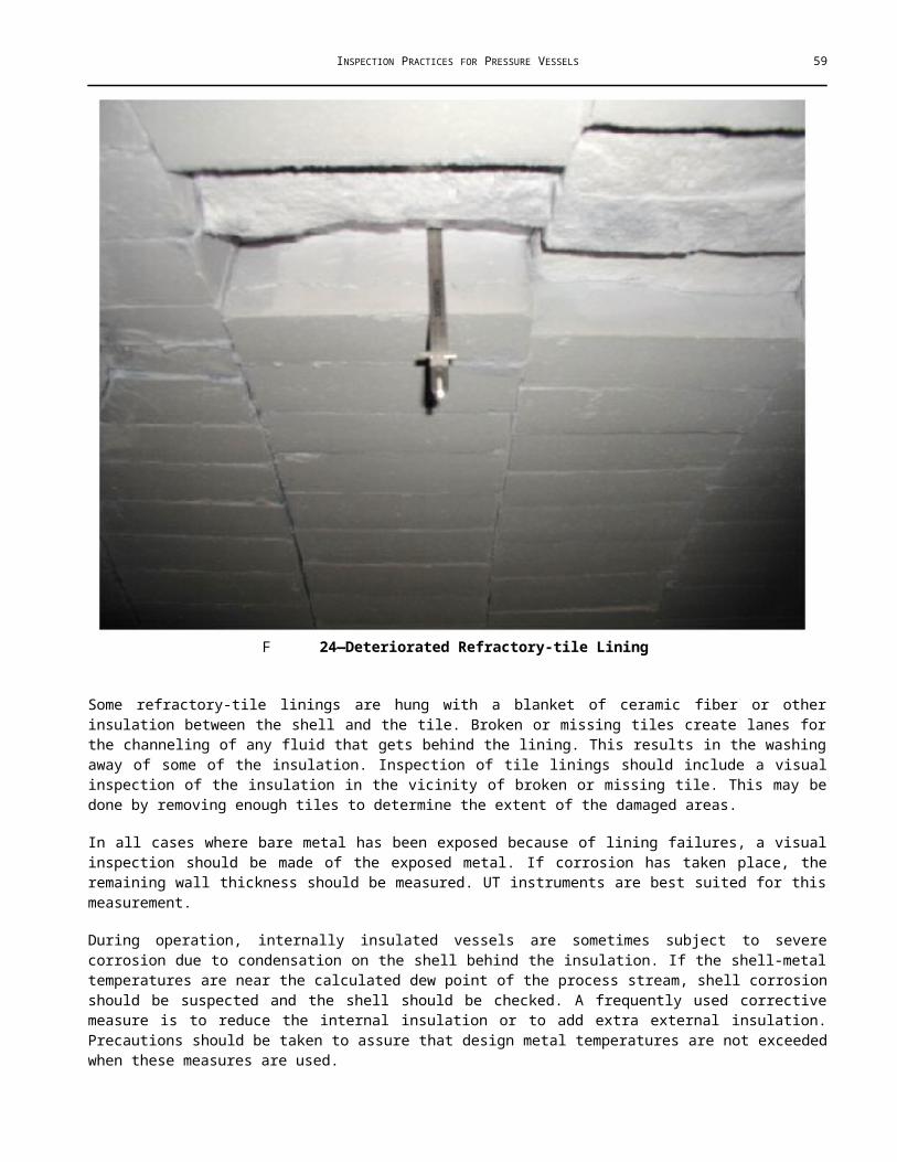
INSPECTION PRACTICES FOR PRESSURE VESSELS 59
A One Fixed Tubesheet with a Floating Head
One type of exchanger consists of a cylindrical shell flanged on both ends, a tube bundle with a tubesheet on both ends, a channel, a channel cover, a floating-head cover for one end of the tube bundle, and a shell cover. The diameter of one tubesheet of the tube bundle is small enough to pass through the cylindrical shell. The diameter of the other tubesheet is large enough to bear on a gasketed surface of one shell flange or may be an integral part of the channel. The bundle is inserted in the shell with the large tubesheet against one shell flange. The channel is bolted to the shell flange that holds the tubesheet in place. The channel and floating heads may be divided so that incoming liquid flows through some of the tubes and returns through other tubes to the channel. The number of divisions and the number of tube flow passes will vary with the design. The flow through the shell is directed by baffles as desired. Since the floating tube end is free to move in the shell, this type of construction permits free expansion and contraction with changes in temperature. This is the type of heat exchanger most commonly used.
A Two Fixed Tubesheets
The construction details for an exchanger with two fixed tubesheets are similar to those of the floating tube-sheet type; however, both tubesheets are fixed and the tubes are installed and rolled after the tubesheets are in place. The shell side cannot be exposed for cleaning. Therefore, it is limited to either clean service or service susceptible to chemical cleaning. Because both tubesheets are fixed, the exchanger is limited to small expansion and contraction unless an expansion joint is provided in the shell.
A One Fixed Tubesheet with U-tubes
A U-tube exchanger has one fixed tubesheet with the tubes bent in the form of a long U in place of the floating head. These exchangers have the same freedom of expansion and contraction as the floating-head type. Clean service is usually limited to the tube side because of the difficulty of mechanically cleaning the inside of the U-tubes. Chemical cleaning, abrasive-grit blasting, or hydroblasting can be used successfully if care is taken not to allow the tubes to become completely plugged.
A Double-tube-sheet Exchangers
In certain services where even minute leakage of one fluid into another cannot be tolerated, double-tube-sheet construction of the exchanger is sometimes employed. As the name implies, two tubesheets are used together with only a small distance, usually 1 in. or less, between them. The tubes are rolled into both tubesheets. The outer tubesheet is attached to the channel, and the inner tubesheet is fixed to the shell. The purpose of this arrangement is to cause any leakage from the tube roll to bleed off into the space between the two sheets, thus, preventing contamination of one fluid by the other. This construction is applicable only where there is no floating tubesheet. Hence, it can be used only with a U-tube exchanger.
A Reboilers and Evaporators
The construction details of reboilers and evaporators are the same as those of any other exchanger with one fixed tubesheet, with the exception that horizontal reboilers have a large vapor space above the tube bundle. They are used to produce vapor from liquids by passing a hot fluid through the tubes.
A Water Heaters
Water heaters may be the floating-head type, U-tube type, or the fixed tube-sheet type. They are used to heat water for boiler feed or for other purposes by exchanging heat from a hot fluid.
A Construction
Exchangers are equipped with baffles or support plates, the type and design of which vary with the service and heat load the exchanger is meant to handle. Pass partitions are usually installed in the channels and sometimes in the

60 API RECOMMENDED PRACTICE 572
floating tube-sheet covers to provide multiple flow through the tubes. The flow through the shell may be single pass, or longitudinal baffles may be installed to provide multiple passes. The baffling used in the shell will determine the location and number of shell nozzles required. Figure A.11 and Figure A.12 show various channel and shell baffle arrangements. Frequently, an impingement baffle plate or rod baffle is located below the shell inlet nozzle to prevent impingement of the incoming fluid on the adjacent tubes.
The tubes may be arranged in the tubesheet on either a square or a triangular pitch. When the fluid circulating around the outside of the tubes may coke or form other dirty deposits on the tubes, the square pitch is generally used. The square pitch arrangement permits better access for cleaning between the tubes.
A Exposed Tube Bundles
A General
Exposed tube bundles are used for condensing or cooling and may be located under spraying water or may be completely submerged. They also may be used as heaters, particularly in tanks where they are submerged in the liquid.
A An Exposed Tube Bundle Under A Cooling Tower
Exposed tubes arranged in compact bundles can be placed under a cooling tower: in this arrangement, the water from the tower flows over the tubes, and heated water is returned to the top of the tower for cooling and reuse. This placement of the tube bundles is most effective in a climate with a low relative humidity resulting in maximum evaporative effect.
A An Exposed Tube Bundle Under Spray Heads
Spray heads may be installed above an exposed tube bundle to provide an even distribution of water over the tubes (this represents a modification of the method described in A.3.2). A receiving tank is located below the tube bundle for use mainly when the water is naturally cool enough to permit recirculation without additional cooling. Where water is plentiful, this type of cooler may be used without a receiving tank, permitting the used water to drain into a treatment system.
A Submerged Exposed Tube Sections
When exposed tube sections are submerged, the sections are mounted either vertically or horizontally within a box. The hot fluid enters the top of the headers in vertical installations and the top section in horizontal installations. In either installation, the cooled fluid leaves at the bottom. Cool water enters near the bottom of the box, and the warmed water overflows a weir near the top of the box. This arrangement produces counter current flow resulting in maximum cooling with a minimum use of water.
Submerged sections are used primarily when a hot fluid leaving the cooler might result in a dangerous condition if the water supply should fail. The large volume of water in the cooler box would give partial cooling for an extended period and allow time for an orderly shutdown of the operation if necessary.
A Storage Tank Heaters
The tube-bundle version of the tank heater is built in three general types for the following installations:
a installation outside the tank,
b installation partially within the tank,
c installation entirely inside the tank.
The first two are installations of suction line heaters, and the third (see Figure A.2) heats the entire contents of the tank.

INSPECTION PRACTICES FOR PRESSURE VESSELS 61
F A.2—Tube-bundle Type of Tank Heater
A Air-cooled Exchangers
An air-cooled unit is similar to an exposed tube bundle unit; however, air is used as the cooling medium. A bank of tubes is located in a steel framework through which air is circulated by a fan placed either above or below the tube bank (a fan above the tube bank is usually referred to as an induced draft air cooler and a fan below the tube bank is usually referred to as a forced draft air cooler). These coolers may be used for the condensing or cooling of vapors and liquids and are installed where water is scarce or for other reasons. Figure A.3 illustrates air-cooled exchangers. (API 661 covers the minimum requirements for design, materials, fabrication, inspection, testing, and preparation for initial delivery.)
F A.3—Air-cooled Exchangers
62 API RECOMMENDED PRACTICE 572
A Pipe Coils
A General
Pipe coils are of two types:
a double-pipe coils,
b single-pipe coils.
A Double-pipe Coils
A General
Double-pipe coils are used when the surface required is small, because they are more economical than the shell or tube type of exchanger in such service. They are also used where extremely high pressures are encountered, because their small diameter and cylindrical shape require a minimum wall thickness.
A Clean-service Double-pipe Coils
Clean-service double-pipe coils consist of tubes within tubes (see Figure A.4). The internal tubes are connected at one end by return bends that are enclosed by return bends connecting the external tubes of the same coil unit. At the opposite end, the internal tubes project beyond the outer tube and through a tight closure that prevents leakage. Internal tubes terminate in piping or are connected to adjacent units with exposed return bends. The external tubes are connected to piping or adjoining external tubes by branch-flanged nozzles.
A Dirty-service Double-pipe Coils
Dirty-service double-pipe coils (scraper-type coils) are identical to clean-service double-pipe coils with the exception that a scraper is added to the inside of the inner tube. Each internal tube is equipped with scrapers mounted on a rod or shaft extending the full length of the tube. The rod projects through the return bends at each end. To prevent leakage, a bearing for the rod is capped at one end, and a bearing and a stuffing box are used at the other end. The rod extends through the stuffing box, and a sprocket is mounted on the end of the rod. The rods and scrapers are rotated by a sprocket chain driven by some form of prime mover, usually an electric motor.
F A.4—Clean-service Double-pipe Coils

INSPECTION PRACTICES FOR PRESSURE VESSELS 63
A Single-pipe Coils
A General
Single-pipe coils are used in several different ways, but essentially all are continuous runs of pipe through which flows a medium to be cooled or heated.
A Condenser or Cooler Coils
Condenser or cooler coils consist of a continuous pipe coil or a series of pipe coils installed in a box through which cold water flows. The pipe coil or coils rest on supports in the box and are free to move with any expansion or contraction. Water enters near the bottom of the box and overflows a weir near the top.
A Chilling Coils
Chilling coils are pipe coils installed in cylindrical vessels to cool a product below atmospheric temperature. Usually, a refrigerant is circulated through the coils to accomplish the cooling. The pipe may be coiled near the internal periphery of the vessel and extend from the bottom to the top or may be arranged as a flat, spiral coil near the bottom of the vessel.
A Flat-type Tank Heater Coils
The flat-type coil extends over most of the bottom of a storage tank and is a continuous coil with return bends connecting the straight runs of pipe. Steam enters one end of the coil, and condensate is drained at the other end through a steam trap. The coil rests on low supports at the bottom of the tank and slopes gently from the inlet to the outlet to facilitate drainage of the condensate. The pipe is usually made of steel, and generally all joints are welded to minimize the probability of leakage.
A Box-type Tank Heater Coils
The box-type coil is constructed in a rectangular shape, as shown in Figure A.5, and extends diametrically from the tank outlet to within a few feet of the opposite side of the tank. The coil is enclosed in a box made of steel or wood. The end of the box opposite the tank outlet remains open to permit the entrance of oil. The oil flows through the box, around the coil, and to the tank outlet. Steam enters the top of the coil and flows downward to the outlet where condensate is drained through a steam trap. The entire coil is sloped gently from the inlet to the outlet to facilitate drainage of the condensate.
F A.5—Tank Suction Heater with Everything but Forward End Enclosed; Shell Suction Nozzle Enclosed in Far End

64 API RECOMMENDED PRACTICE 572
A Extended Surface or Fin-type Tubes
Extended surface or fin-type tubes are used quite extensively for more efficient heat exchange, especially when the exchange is between two fluids having widely different thermal conductivities. The addition of the extended surface requires less internal tube surface. Consequently, an exchanger smaller than would be required if plain tubes were used is necessary. The use of fin-type tubes in a double-pipe coil is shown in Figure A.6.
F A.6—Fin-type Tubes in Double-pipe Coil
A Plate-type Exchangers
The plate-type exchanger is also constructed with an extended surface, making use of alternating layers of thin plates and corrugated sections. Integral channel and manifold sections enclose the open ends. The process material flows into the corrugated openings. Because the flow openings are small, they are easily clogged by dirt and products of corrosion. This is one of the reasons these units are constructed of materials that are highly resistant to corrosion. A plate-type exchanger installation for storage tank heating service is illustrated in Figure A.7.

INSPECTION PRACTICES FOR PRESSURE VESSELS 65
F A.7—Plate-type Exchanger
A Inspection of Exchanger Bundles
A General
The first step in bundle inspection is a general visual inspection that may establish general corrosion patterns. If possible, bundles should be checked when they are first pulled from the shells, because the color, type, amount, and location of scales and deposits often help to pin point corrosion problems. An overall, heavy scale buildup on steel tubes may indicate general tube corrosion. The lack of any scale or deposit on tubes near the shell inlet may indicate an erosion problem. A green scale or deposit on copper base tubes indicates that these tubes are corroding. As an inspector gains experience, these scales and deposits will become a useful inspection guide.
While visually inspecting a bundle, the inspector should make use of a pointed scraper to pick at suspected areas next to tubesheets and baffles. These areas may not have been cleaned completely. Picking in these areas will sometimes disclose grooving of tubes and enlargement of baffle holes. Figure A.8 shows tubes thinned at baffles.
F A.8—Tubes Thinned at Baffles

66 API RECOMMENDED PRACTICE 572
F A.9—Tubes Fretting at Baffles
Tapping the tubes with a light [4 oz to 8 oz (115 g to 225 g)] ball peen hammer or inspection hammer during the visual check will often help in locating thinned tubes. This method is especially useful when inspecting light-wall tubes of small outside diameters. The amount of rebound and the sound of the blow give an indication of the tube wall thickness. This method will become more helpful as experience is gained in the use of the hammer.
The inside of the tubes can be partially checked at the ends by use of flashlight extensions, fiber optic scopes, borescopes, and special probes. The special probes are slender 1⁄8-in. (3.2 cm) rods with pointed tips bent at 90 to the axis of the rod. With these tools, it is possible to locate pitting and corrosion near the tube ends.
Obviously, only the outer tubes of a bundle can be thoroughly inspected externally, and without a borescope or fiber optic scope, only the ends of the tubes can be inspected internally. If a complete inspection of the tubes for defects is required, it can be made by using ET methods or UT methods (for internal rotary, UT thickness measurements).
Tubes may also be removed from the bundle and split for visual inspection. There are devices available for pulling a single tube from a bundle.
Removal of one or more tubes at random will permit sectioning and more thorough inspection for determining the probable service life of the remainder of the bundle. Tube removal is also employed when special examinations, such as metallurgical and chemical ones, are needed to check for dezincification of brass tubes, the depth of etching or fine cracks, or high-temperature metallurgical changes. When bundles are retubed, similar close inspection of tubes removed will help to identify the causes of failure and improve future service.
The baffles, tie rods, tubesheets, and floating-head cover should be visually inspected for corrosion and distortion. Gasket surfaces should be checked for gouge marks and corrosion. A scraper will be useful when making this inspection. Sufficient gasketed surface should remain to make a tight seal possible when the joints are completed.
Tubesheets and covers can be checked for distortion by placing a straight edge against them. Distortion of tubesheets can result from the overrolling or improper rolling of tubes, thermal expansion, explosions, rough handling, or overpressuring during a hydrotest.
Tube-sheet and floating-head thickness can be measured with mechanical calipers. Except in critical locations, continuous records of such readings are not usually kept. However, the original thickness readings of these parts should be recorded. Thickness readings of tie rods and baffles are not generally taken. The condition of these parts is determined by a visual inspection.
Tube wall thickness should be measured and recorded at each inspection. It is sufficient to measure the inside and outside diameters and to thus determine the wall thickness. Eccentric corrosion or wear noted during the visual inspection should be taken into account in determining the remaining life of the tubes.

INSPECTION PRACTICES FOR PRESSURE VESSELS 67
Several tools are available for the assessment of tube conditions. Long mechanical calipers can be used to detect general or localized corrosion within 12 in. (30.5 cm) of the tube ends. More detailed measurements along the entire tube length can be achieved with specialized tools such as laser optical devices, internal rotary UT tools, and electromagnetic sensors. Generally, the laser optical and UT devices require a high degree of internal tube cleanliness compared to electromagnetic methods. Laser optical devices can only detect and measure internal deterioration. Electromagnetic methods can detect and provide semiquantitative information on both internal and external defects. Rotary UTs will generally provide the most quantitative information and can identify if defects are on the internal or external surface of the tube.
A Likely Locations of Corrosion
The locations where corrosion should be expected depend on the service of the equipment. However, there are certain locations that should be watched under most conditions of service.
The outside surface of tubes opposite shell inlet nozzles may be subject to erosion or impingement corrosion. When a mildly corrosive substance flows on the shell side of the tube bundles, the maximum corrosion often occurs at these inlet areas. The next most likely point of attack under the same conditions would be adjacent to the baffles and tubesheets. Any deterioration here is probably erosion-corrosion (see Figure A.10).
F A.10—Erosion-corrosion Attack at Tube Ends
When a high-temperature material flows into the tube inlet pass, the backside of the stationary tubesheets or tubes immediately adjacent to it may suffer extensive corrosion.
When process conditions allow a sludge or similar deposit to form, it will generally settle along the bottom of the shell. If the deposit contains a corrosive material, the maximum corrosion will occur along the bottom of the shell and the bottom tubes.

68 API RECOMMENDED PRACTICE 572
In water service, the maximum corrosion will occur where the water temperature is highest. Thus, when the water is in the tubes, the outlet side of the channel will be the location of maximum corrosion. Figure 27 shows pitting in a channel.
Also in water service, when exchanger parts are made of gray cast iron, they should be checked for graphitic corrosion. This type of attack is most often found in water-service channels or along the bottom of shells where sour water might collect. It can be found by scraping at suspected areas with a stiff scraper. Whether the attack is serious depends on its location and depth. Quite often, pass partitions can be almost completely corroded and still function efficiently, unless the carbon shell is broken or chipped.
In any type of exchanger, corrosion may occur where dissimilar metals are in close contact. The less noble of the two metals will corrode. Thus, carbon steel channel gasket surfaces near brass tubesheets will often corrode at a higher rate than they would otherwise.
Cracks are most likely to occur where there are sharp changes in shape or size or near welded seams, especially if a high stress is applied to the piece. Parts such as nozzles and shell flanges should be checked for cracks if excessive stresses have been applied to a unit.
When process stream velocities are high in exchangers, erosion damage can be expected at changes in the direction of flow. Damage would occur on or near such parts as tube inlets in tubular units and at return bends in double-pipe units and condenser box coils. The area of the shell adjacent to inlet impingement plates and bundle baffles is susceptible to erosion, especially when velocities are high.
A distinctive prussian blue color on bundle tubes indicates the presence of ferri-ferrocyanide. Hydrogen blistering is likely to be found on the exchanger shell near this color. A long straightedge may prove useful in determining the existence of blistering. Irregularities of the surface show up when the straightedge is placed on it. A straightedge is also useful when investigating pitting.
A Inspection of Coils and Double-pipe Exchanger Shells
Basically, coils in open condenser boxes and double-pipe exchanger shells are composed of pipe. They should be inspected according to the procedures detailed in API 574. (See Annex B for a sample form for making an inspection report on a double-pipe exchanger.)
First, a thorough visual inspection should be made, including a complete hammering of the pipe. A scraper may be used to detect external pitting, a common defect found on the outside of coils in condenser boxes.
Following the visual inspection, thickness measurements should be taken. It is generally sufficient to use calipers to measure the open ends of double-pipe exchanger shells. To measure the wall thickness of coils and the middle section of double-pipe shells, UT and ET devices can be used.
The enclosures of condensers or cooler boxes are made of concrete or light-gauge carbon steel. These enclosures should be visually inspected when the enclosed coil is inspected. When the container is made of carbon steel, the hammer is the most useful inspection tool available to aid the visual check. Thin spots in the container wall can be found by hitting the wall with the hammer. Calipers can be used to measure the wall thickness at the open top. If measurements below the top are required, the NDE instruments can be used or test-hole drilling can be applied. Concrete walls are inspected best by picking at selected points with a scraper to check for spalling, cracks, or soft spots.
A Inspection of Extended Plate Exchangers
Extended plate exchangers are designed so that the flow openings between the plates are quite small. For this reason and because of the inaccessibility of the unit interior, these exchangers are usually built of alloys highly resistant to corrosion in their expected service. In most cases, the alloys used also will be highly resistant to corrosion in refinery atmospheres. Visual examination, except as discussed in 10.8.3, will not reveal much. The outer surfaces can be

INSPECTION PRACTICES FOR PRESSURE VESSELS 69
checked for nicks, cuts, gouges, or other forms of mechanical damage and for bulging from internal failures. Good lighting is essential for this inspection and will prove valuable when performing the soap tests discussed in 10.8.2.
These units are usually built with integral channels and distribution manifolds, the thickness of which can be accurately measured with the UT instruments and then recorded. It is not advisable to use drilling equipment on the exchangers because the equipment could be easily damaged at these points. Welding of the alloys used in the units, such as aluminum and austenitic stainless steel alloys, requires welder skills not always readily available.
Light tapping with a small [8 oz. (225 g)] hammer is useful in looking for cracked or broken parts on the exposed portions of the extended plate exchangers. The sound of the blow gives a clue to the condition. Cracked plates or manifold sections give off a tinny sound, which can be recognized more easily as more experience is with the use of a hammer is acquired.
A Inspection of Air-cooled Exchangers
Refer to API 661 for descriptions, minimum design criteria, and general information regarding air-cooled exchangers. API 510 and the principles of API 661 are to be followed in any ratings, repairs, and alterations of this type of exchanger. (See Annex B for a sample form for making an inspection report on an air-cooled exchanger.)
Tubes that are enclosed in fins cannot be inspected from the exterior. The best methods for inspecting the tubes are the internal-rotary, UT thickness-testing devices, ET, or remote field ET. These methods work from the interior of the tubes. With competent operators and clean tubes, thicknesses and defects can be found with these methods. The tubes must be thoroughly cleaned before any method is effective.
The external fins of the tubes should be checked for cleanliness. If the fins need cleaning, washing with clean water alone or clean water with soap may be sufficient. If not, care should be taken in selecting a cleaning solution. Usually, the fins are aluminum and they could be harmed if the wrong cleaning medium is used.
The exterior of the tubes should be inspected between the tubesheet and the start of the fins. Exchangers in intermittent service or in service cool enough to allow moisture to collect in this area are subject to external corrosion severe enough to cause leaks in this area. Coatings applied to this area will alleviate the problem of corrosion.
The insides of the tubes may be visually inspected near the tube-sheet ends of the air cooler. Fiber optic devices and borescopes are excellent devices for this type of inspection. A probe rod 1⁄8 in. (3.2 mm) or less in diameter and approximately 36 in. (91 cm) in length with a pointed tip bent at 90 to the axis of the rod also may help to locate pits or corrosion at the tube ends.
Erosion-corrosion at the tube inlets is a common problem with air-cooled heat exchangers. This damage can be found by visual inspection through the header-box plug holes, or directly if the header box has a removable cover plate. If suitable conditions exist, reflecting sunlight into the tubes with a mirror is useful in inspecting for erosion-corrosion.
The box-type header ends of the air cooler should be inspected using the same techniques as recommended for a pressure vessel. In addition, the sharp change of direction caused by its rectangular construction should be carefully checked for cracking. The header boxes with removable cover plates are obviously the easiest to inspect. A fiber optics scope may be the only way to check a header that has plug-type closures as opposed to a cover plate.

70 API RECOMMENDED PRACTICE 572
1 stationary head—channel 21 floating-head cover—external
2 stationary head—bonnet 22 floating tube-sheet skirt
3 stationary-head flange—channel or bonnet 23 packing box
4 channel cover 24 packing
5 stationary-head nozzle 25 packing gland
6 stationary tubesheet 26 lantern ring
7 tubes 27 tie rods and spacers
8 shell 28 transverse baffles or support plates
9 shell cover 29 impingement plate
10 shell flange—stationary-head end 30 longitudinal baffle
11 shell flange—rear-head end 31 pass partition
12 shell nozzle 32 vent connection
13 shell-cover flange 33 drain connection
14 expansion joint 34 instrument connection
15 floating tubesheet 35 support saddle
16 floating-head cover 36 lifting lug
17 floating-head flange 37 support bracket
18 floating-head backing device 38 weir
19 split shear ring 39 liquid level connection
20 slip-on backing flange
Legend
NOTE AES refers to heat exchanger type (see Figure A.12).
F A.11—Heat Exchanger Parts

INSPECTION PRACTICES FOR PRESSURE VESSELS 71
F A.11—Heat Exchanger Parts (continued)

72 API RECOMMENDED PRACTICE 572
F A.11—Heat Exchanger Parts (continued)

INSPECTION PRACTICES FOR PRESSURE VESSELS 73
F A.11—Heat Exchanger Parts (continued)

74 API RECOMMENDED PRACTICE 572
F A.12—Heat Exchanger Types

INSPECTION PRACTICES FOR PRESSURE VESSELS 75
A(informative)
Towers
B General
Towers all either directly enrich a gas or liquid, strip a gas or liquid, or fractionate a liquid. These processes are collectively called “mass transfer.” Towers or columns (the terms tower and column are used interchangeably within the petrochemical industry) come in a wide variety of shapes and sizes, but the one thing they all have in common is base purpose, that is, they all at the very basic level, promote, cause, contain, allow, encourage, or otherwise make “mass transfer” happen. The difference in concentration of a particular molecule is the prime mover in mass transfer. Molecules move from an area of high concentration to an area of low concentration. The mass transfer in a tower is usually from a liquid to a gas or from a gas to a liquid. The most common types of towers use contacting elements such as trays or packing to facilitate mass transfer between a gas and a liquid (see Figure B.1 and Figure B.2). Both packing and trays accomplish this by increasing the available surface area for the gas/liquid contact.
F B.1—Typical Trays in a Tower
F B.2—Random Packing in a Tower

76 API RECOMMENDED PRACTICE 572
In addition to increasing contact area (and increasing contact time), trays allow additional distillation to take place at each tray.
Tray decks both increase the available contact area and provide additional distillation stages to take place as the hot gases rise through the tray perforations. Liquid levels are maintained on the trays via weirs, and a vapor seal is maintained via downcomers. Figure B.3 diagrams how the trays with downcomers work.
F B.3—Trays with Downcomers
Gases/vapors, released from the feed liquid (after being heated), travel up the column through the tray perforations (the bubble cap depicted in Figure B.4 is a type of tray perforation) while liquid flows across the trays and down the tower via the downcomers from the feed inlet down to the stripping section (countercurrent flow). The area above the feed inlet is known as the rectification or enrichment section. The enrichment section utilizes a liquid reflux of condensed overhead gas to further enrich the overhead product.
F B.4—Bubble Cap Flow Path

INSPECTION PRACTICES FOR PRESSURE VESSELS 77
Most of the towers used in the petrochemical industry utilize the distillation-type stripping process described above and depicted in Figure B.5; however, in cases where distillation is impractical, liquid-liquid extraction accomplishes mass transfer utilizing the difference between the chemical structures of two liquids. Liquid-liquid extraction necessitates recovery of solvent or raffinate via distillation stripping. Some other types of mass transfer operations which utilize distillation-type stripping are stripping, absorption (also known as scrubbing), and dehydration. Fractionation uses simple distillation via selective cooling to remove and collect those fractions of the feed which boil and condense at different temperatures. The heat source needed to cause phase change (liquid to gas) can be fired heaters, steam injection, steam reboilers, or reboilers using preheated process streams.
F B.5—Tower Stripping and Rectification Section

78 API RECOMMENDED PRACTICE 572
B Trayed Towers
B General
Trayed towers consist of cylindrical shell courses with both top and bottom heads, with nozzles where appropriate, filled with tray decks to facilitate the gas/liquid contact. They may also include conical transition sections, internal sumps/baffles, demisters, inlet distributors, or a variety of other components. Multiple towers may even be fabricated as a single pressure vessel, stacked on top of each other.
Trayed towers come in several different configurations, from cascade-type trays such as disk and donut trays to sieve trays, bubble cap trays and high capacity valve trays.
B Cascade Trays
The two most common types of cascade trays are shed trays and disk/donut trays. Cascade trays utilize a different approach to gas/liquid contact than regular trays. Shed trays may be anything from angle iron to half pipes. Large numbers of shed trays are arranged in rows, installed perpendicular to each other and to the gas and liquid flow such that breakup of the falling liquid takes place. Gas flow up through the droplets of liquid is the primary source of contact for mass transfer. In disk/donut trays (see Figure B.6) the disks and donuts are installed in alternating sequence, with the donuts mounted to the shell, and the disks suspended in the center of the tower, with both the disks and the donuts being perpendicular to the gas and liquid flow. As liquid repeatedly cascades from the disks to the donuts, sheeting and breakup of the liquid takes place.
F B.6—Disk/Donut Tray

INSPECTION PRACTICES FOR PRESSURE VESSELS 79
F B.7—Baffle Tray Arrangement
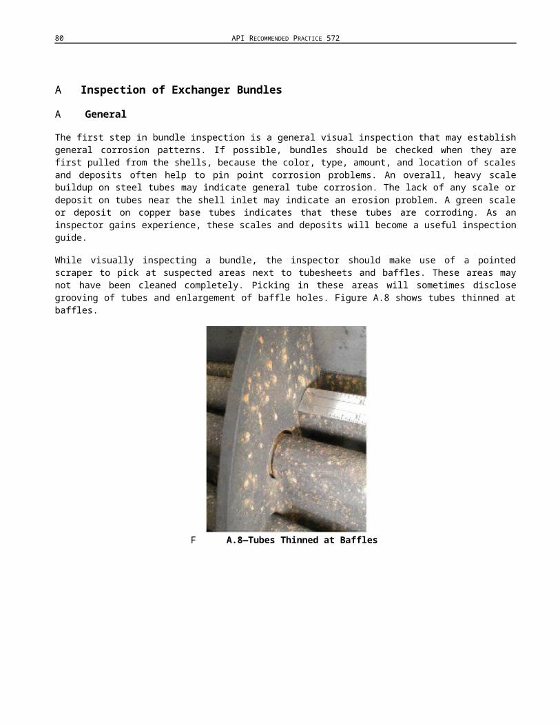
80 API RECOMMENDED PRACTICE 572
Baffle trays (sometimes called “splash trays”) are solid baffles, installed on alternating sides, perpendicular to the gas/liquid flows. These individual trays each typically obstruct about 60 % of the tower to ensure that the falling liquid impacts the tray below. The baffle tray arrangement is depicted in Figure B.7.
Contact with the falling and/or splashing droplets is the main source of liquid/vapor contact for all cascade-type trays. Internals associated with cascade trayed towers are usually limited to simple pipe inlet distribution with steam spargers in the bottom to provide heating and gas flow volume.
B Sieve Trays
Sieve trays are tray plates with perforations in them similar to a sieve (see Figure B.8), hence the name. No valves are present. Sieve trays can be subdivided into single-flow and dual-flow trays. Single flow refers to the flow through the tray perforations. On single-flow trays, the primary flow path of the liquid is across the tray and down the downcomer to the tray below.
F B.8—Sieve Tray
The downcomers act to transport the liquid to the next tray, and promote disengagement of the gas and the liquid. The primary flow path of the gas on single-flow trays is through the tray perforations. The perforations in single-flow sieve tray are sized with this in mind. Single-flow sieve trays are customarily used where light-to-moderate fouling by precipitates and/or polymers is anticipated.
Dual flow also refers to flow through the tray perforations. On dual-flow trays, there are no downcomers. The primary flow path of both the descending liquid and the ascending gas is through the tray perforations. In response to liquid falling from above and gas bubbling from below, the standing liquid on the tray forms waves throughout the liquid. Gas flow up is primarily at the wave troughs, and liquid flow down through the perforations is primarily at the wave crests. Jet tabs similar in appearance to very small upward facing scoops are utilized to promote even liquid flow throughout the sieve tray. Ripple trays are a type of dual-flow tray which magnifies the crest/trough relationship via the corrugated design of the tray panels. Dual-flow trays are customarily used for processes which exhibit heavy fouling due to the formation of precipitates or polymers. Both types of sieve trays have better anti-fouling characteristics than standard valve trays, but must operate in a very limited range of operating conditions to be efficient.

INSPECTION PRACTICES FOR PRESSURE VESSELS 81
Sieve trays must be installed and maintained level. Sieve trays which are not level can rapidly lose efficiency due to blow through where areas of the liquid level on the tray are shallow. Figure B.9 show a sieve tray that has been distorted.
F B.9—Sieve Tray Distortion
B Valve Trays
Valve trays are trays that have valves installed at the perforations in the tray deck. Perforations are typically larger than those in sieve trays, as well. The advantage of valve trays over sieve trays is that the valve is able to close, or in the case of floating valves even partially close, allowing the pressure of the rising gas to be maintained. This allows the tower to operate over a much wider range of operating conditions than sieve trays would allow (Figure B.10 to Figure B.16 show typical tower drawings and types of valves). Trays are frequently designed to have more than one weight of valve installed, to allow balancing of gas flow through the tray. This also allows the back pressure below the tray to be maintained. Valve trays can be subdivided into fixed valve and floating valve trays.

82 API RECOMMENDED PRACTICE 572
F B.10—Typical Trayed Tower

INSPECTION PRACTICES FOR PRESSURE VESSELS 83
B Fixed Valves
Bubble cap trays are fixed valve trays. For a good portion of the history of fractionation trays, bubble caps were the only tray valve. Bubble caps remain in service throughout the industry in systems where low liquid flow rates and high variations in vapor flow and resistance to heavy fouling are required. Bubble caps come in a variety of shapes and sizes, from round (mushroom caps) to rectangular (brick or bread loaf caps) in both slotted caps and solid (FRI [fractionation research incorporated-type (FRI-type)] caps.
While operating ranges are less than those allowed by moveable valve trays, significant increases in operating ranges and efficiency over sieve trays and bubble cap trays are possible using fixed valves extruded from the tray decks. Fixed valves offer lateral gas flow to inhibit fouling rather than the vertical gas flow of sieve trays, and higher mechanical strength than floating valve trays, with no moving parts to wear out.
F B.11—Float Valves with Two Weights

84 API RECOMMENDED PRACTICE 572
F B.12—Fixed Valves
F B.13—Bubble Cap Valves

INSPECTION PRACTICES FOR PRESSURE VESSELS 85
F B.14—Extruded Valves
Newer fixed valve designs offer even greater operating ranges, efficiency and fouling resistance but at the cost of losing the single piece construction of the extruded valves and at the cost of additional wear as valve tabs loosen or corrode.
B Floating Valves
Moving or floating valve trays are trays in which valves have been inserted into or are placed above the tray perforations. These valves are retained in the tray perforations via bent or twisted “feet” and/or are kept positioned above the perforations by cages tabbed to the tray deck. Valves are allowed to move freely (or “float”) from the closed position (down) through fully opened (up) position as pushed by the vapor pressure below the tray. This allows very high turndown ratios, and much less weeping than conventional fixed valve or sieve trays. As with the fixed valves, the horizontal gas flow limits entrainment and fouling.
Valves may be smooth edged, or provided with tabs and/or dimples on the edges to prevent rotation and sticking of the valves (due to vapor lock between the valve and tray deck), respectively. Floating valves may be round or rectangular in shape. Floating valve trays of either type offer a higher efficiency (liquid/vapor contact) over a much wider operating range than sieve trays due to their ability to control vapor flow. Multiple valve weights are frequently installed in the same tray to widen the operating range. Caged valves are frequently utilized in low liquid flow systems.

86 API RECOMMENDED PRACTICE 572
F B.15—New Floating Valve Tray
F B.16—Caged Valves
B Packed Towers
B General
Packed towers all have basically the same configuration, with the only significant variable being the type of packing used. Packed towers have one or more packing beds, supported by bed supports, with distribution systems above the bed to ensure even wetting of the packing (see Figure B.17).

INSPECTION PRACTICES FOR PRESSURE VESSELS 87
F B.17—Typical Packed Tower Drawing

88 API RECOMMENDED PRACTICE 572
Bed limiters may or may not be installed and may be integral to the distribution system. Collector (chimney trays)/redistributors are commonly used between packed beds and in some services are installed below the bottom bed as well. Due to the larger surface area available for mass transfer, packing has the advantage of being able to handle larger liquid rates with higher efficiencies and with lower pressure drop than all but the newest of the high capacity trays. Packing can be subdivided into random packing and structured packing.
B Random Packing
Random packing takes its name from the method in which it is loaded, i.e. allowed to fall at random onto the bed supports. Random packing comes in a variety of sizes, from 0.50 in. in diameter to 3 in., and can be custom ordered in any size and almost any material, from carbon steel to ceramic and plastic. Random packing shapes range from the original raschig rings through pall rings and various “super rings.” Figure B.18 shows pall rings for random packing.
F B.18—Random Packing, Pall Rings
Random packing provides low pressure drop, high capacity and high efficiency, without the maintenance cost of fractionation trays, but is typically more expensive for large diameter columns. Random packing is less than ideal for large diameter towers with low liquid flow rates and high vapor flow rates due to the difficulty in maintaining packing wetting throughout the bed at low liquid rates.
B Structured Packing
Structured packing gets its name from the fact that it's assembled into blocks to facilitate loading and assembly into beds. Structured packing is constructed of corrugated metal (typically, a noncorrosive high alloy) arranged such that the corrugations oppose one another. The corrugated metal is then bound into blocks. Most structured packing is installed such that each succeeding layer is 90out from the previous layer, this can be noticed in Figure B.19 of structured packing. This allows an interfacial area for mixing and spreading of the liquid throughout the packing. Surface texturing is frequently present on the sheet metal to increase wetting and instill turbulence in the gas flow which facilitates mass transfer. Depending on service, wall wiper rings may be installed at each layer to rechannel any liquid or vapor which has migrated to the wall.

INSPECTION PRACTICES FOR PRESSURE VESSELS 89
F B.19—Structured Packing
Within its operating range, structured packing provides higher capacity and lower pressure drop than crosscurrent trays or random packing.
Packing bed support grids and hold downs are typically much larger spaced. Frequently, box and trough distribution systems may be placed directly upon the bed, with little other support required. Grid-type packing is commonly utilized in heavy fouling service. The surface of grid-type packing is invariably smooth to allow any particulates to wash off inhibiting coke formation. The grid-type packing is depicted in Figure B.20.

90 API RECOMMENDED PRACTICE 572
F B.20—Grid-style Packing
B Inspection of Towers
B General
Due to the complicated structure of a tower and the wide variations in feed sources possible in today’s petrochemical market, past reports and current prints are invaluable aids in performing a thorough visual inspection. Past turnaround reports provide critical data on the location and severity of ongoing corrosion and wear. An up-to-date or corrected elevation drawing of the tower not only allows those previously identified problems to be mapped out for analysis and makes following capital work easier, it also allows inspection progress to be easily tracked, while ensuring that those same history items are not overlooked.
With towers, should an external visual inspection be required it is customary to perform the external inspection on the way up the tower. External Inspection from the bottom up and internal inspection from the top down is the customary method.
The following tools at a minimum should be with the inspector when they climb the tower to begin the inspection.
— 4 oz to 6 oz ball peen hammer,
— inspection light (flashlight),
— digital camera,
— pit gauges,
— scratch awl,
— scraper,
— tape measure,
— paint markers,
— wire toothbrush,
— notebook and pens/pencils,
— carpenter's or plumber's level,
— inspection mirror,
— sample bags.
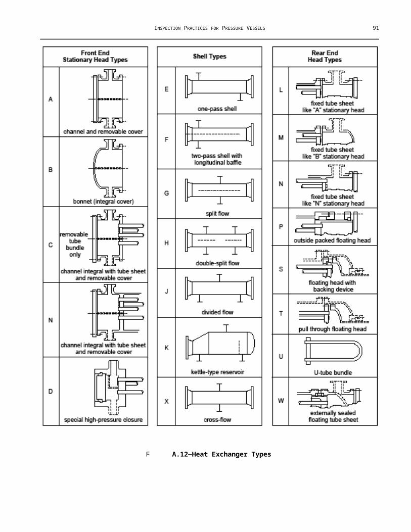
INSPECTION PRACTICES FOR PRESSURE VESSELS 91
Photography and Inspection—It is not possible to take too many photographs of the condition of a distillation tower. Cameras have long been an important tool for inspection, and the advent of digital photography has made a pictorial record of the actual condition of a tower easy and inexpensive. Care should be taken to ensure that proper permissions and permitting are obtained for photography in the course of inspections.
B Safety
Combining confined space entry, the large, convoluted interior spaces typically found inside towers and the mobility involved in completing the internal inspection in a timely manner makes internal inspections of trayed towers inherently dangerous. Where possible, two inspectors should be assigned when working with very large towers. In addition to the normal precautions associated with confined space entry for internal visual inspection (careful reading of any permits, and any job safety analysis or its equivalent which might be required in the facility in which you are working), the following additional safety precautions are advisable.
1 Prior to entry, ensure that the entry attendant(s) is familiar with the internal configuration of the tower, and understands the physical basics of your task, such as climbing on and across trays, moving between trays, and of the access and egress point which have been approved.
2 Prior to entry, ensure that the entry attendant, the inspector(s) and any other persons involved with the internal inspection understand the limits of the approved communication method. When visual contact is lost, most facilities rely on radio communication between the entrant(s) and the entry attendant. The extreme noise level inherent to common forced ventilation methods may prevent verbal communication. Communication sounds and meanings should be worked out in advance to be effective.
3 Prior to entry, ensure that scaffolding, where required for entry, access to the internals and/or egress from the vessel, is installed. The presence of scaffold from the bottom head to the bottom tray (see Figure B.21) and bridging any extra wide tray spacing such as that found at distributors or transition sections should be confirmed prior to performing this visual inspection.
4 Tray manways (see Figure B.22) can be extremely easy to traverse in one direction, but very difficult in the opposite direction. Tray hardware and sharp corners can catch on clothing or exposed skin.
5 Release of gases and vapors from under debris and/or from under liquids such as water left after washing or steam out is possible. Such conditions should be addressed prior to beginning the inspection where visible, and prior to completion of the inspection when discovered in situ. Figure B.23 depicts a dangerous condition that shall be assessed and dealt with prior to internal inspection.
6 Upset tray decks are inherently dangerous platforms for climbing. Care should be taken to distribute weight evenly while performing damage assessments. Use of fall protection and/or retrieval devices is highly recommended under upset conditions. Fall protection is also highly recommended in towers where severe tray thinning is suspected.
7 Wherever possible, hard ladders such as scaffold ladders should be utilized, to allow sufficient time and stability for visual inspection. Where hard ladders are not possible, yo-yo type fall protection (see Figure B.24) should be used in conjunction with the rope, strap or other soft ladders.
8 All distributors which are obstructing internal or external manways should be temporarily removed to allow access and emergency egress.

92 API RECOMMENDED PRACTICE 572
F B.21—Diagram of Required Scaffolding
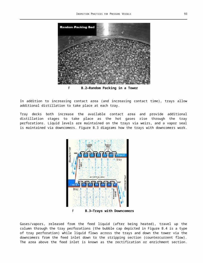
INSPECTION PRACTICES FOR PRESSURE VESSELS 93
F B.22—Hexagonal Manways
F B.23—Standing Oil and Water

94 API RECOMMENDED PRACTICE 572
F B.24—Trays Collapsed
B External Inspection
The Anchor Bolts—Due to the leverage applied by the height of the tower and the corrosion masking effect of fireproofing, particular care should be taken when inspecting the anchor bolting of towers (see Figure 25 and Figure 26).
Skirt Fireproofing—Any crack over 0.250 in. in width, and any crack which has displacement or bulging of the concrete fireproofing material should be investigated for corrosion under fireproofing (CUF). Identifying CUF, as with CUI, is a primary focus of today's mechanical integrity programs. Figure B.27 shows cracks within a towers fireproofing.
F B.25—Corroded Anchor Bolting

INSPECTION PRACTICES FOR PRESSURE VESSELS 95
F B.26—Corroded Anchor Bolting
F B.27—Cracked and Bulged Fireproofing
Tower skirts should be inspected for debris and skirt drains should be checked for obstructions. Debris in the skirt (see Figure B.28) is a fire hazard, and obstructed skirt drains foster corrosion of the anchor bolting and skirt, as well as allowing minor leakage at the bottom head/nozzles/flanges to go undetected.
B Internal Inspection
Those tools which are normal to the visual inspector (see 8.2) are sufficient for the inspection of towers. No special tools or equipment are required to perform internal visual inspection of a tower.

96 API RECOMMENDED PRACTICE 572
Preliminary, or “dirty inspections” shown in Figure B.29 through Figure B.35, should be performed upon opening the external manways, before whatever forced ventilation is to be installed is installed. Early detection of previously unexpected damage to internals due to upset and/or corrosion is crucial to the timely completion of repairs.
Determination of the degree of additional cleaning which might be required is crucial to the timely completion of discovery work. Hand cleaning of those areas not adequately cleaned via steam out and chemical cleaning is frequently required due to the complexity of the internal configurations.
Using the equipment elevation drawing, manway covers; manway gasket surfaces and manway bore internal surfaces should be labeled and inspected.
F B.28—Debris in Skirt
F B.29—Preliminary Inspection

INSPECTION PRACTICES FOR PRESSURE VESSELS 97
F B.30—Bed Damage at Preliminary Inspection
F B.31—Manway Corrosion
F B.32—Manway Liner Damage

98 API RECOMMENDED PRACTICE 572
F B.33—Corrosion on Gasket Seating Surface
F B.34—Corrosion on Gasket Seating Surface
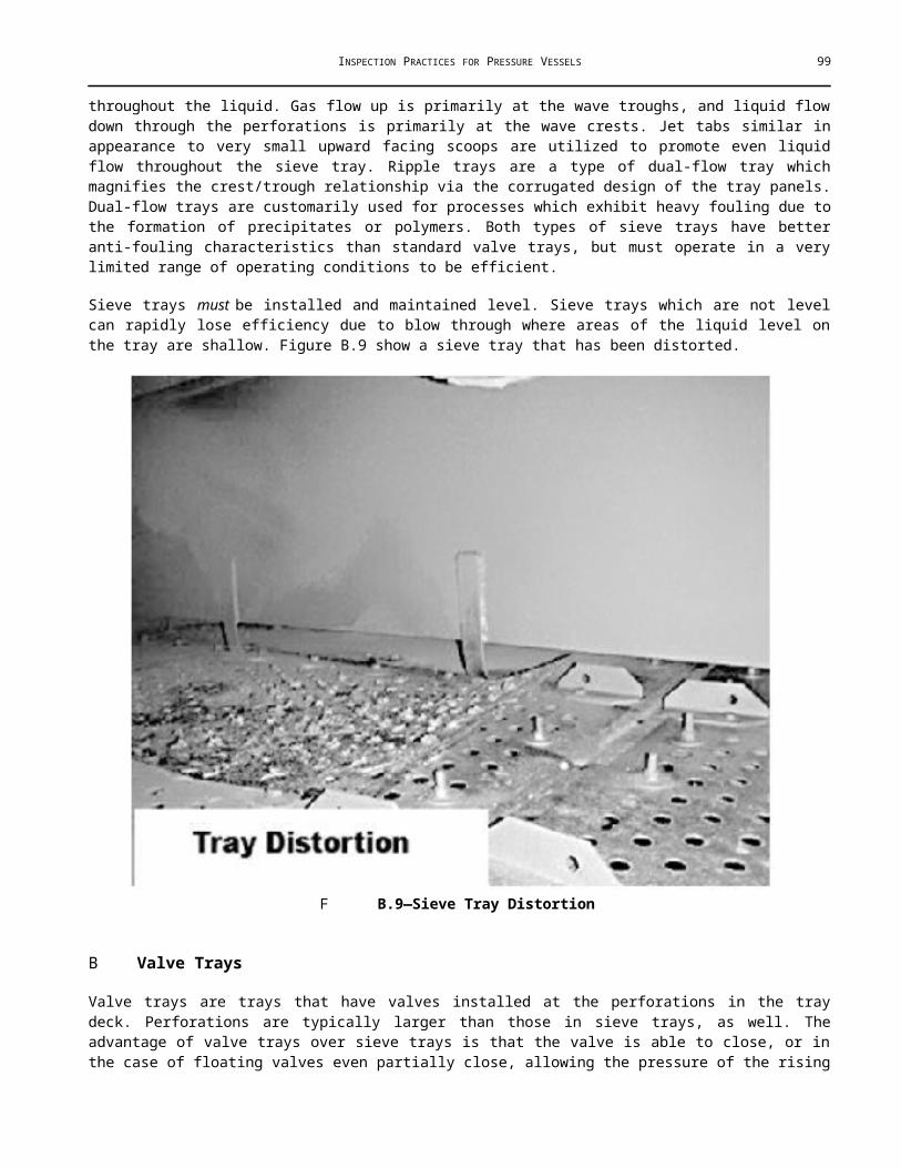
INSPECTION PRACTICES FOR PRESSURE VESSELS 99
F B.35—Surface Corrosion of Shell
Particular care should be taken with lined manways and covers.
Cracking and bulging at liner plug welds and consequential corrosion behind the liner, corroded or damaged gasket surfaces and/or internal corrosion of the bore or stagnant areas should be discovered prior to installation of ventilation equipment.
B Visual Inspection of Packed Towers
B General
Packed towers have two basic sets of conditions; packing removed and packing in place. If packing is not removed, a limited or partial visual inspection is the most which can be performed. Under these conditions, the degree of inspection is a variable, controlled by the degree of disassembly of the internals, the type of packing and the amount of access permitted by operations.
B Packed Towers—Packing in Place
Inspection of a tower with packing in place is limited to the top and bottom heads, the adjacent shell, and those other portions of the pressure retaining boundary that are accessible, the accessible nozzle bores, the top and bottom surface packing and the internals (Figure B.36 and Figure B.37 demonstrate the limited visibility of a packing in place inspection).

100 API RECOMMENDED PRACTICE 572
F B.36—Inspection From the Bottom Head
F B.37—Inspection of Packing via Riser
Normal visual inspection and quantification of the surface texture and corrosion present on the top head and shell course may be supplemented with UT thickness measurements. Thickness measurements of susceptible areas or areas of visible impingement should be taken in conjunction with the visual inspection throughout the tower. Such areas of impingement can frequently be found above demister pads, and are indicative of pad bypass, usually due to improper installation or breakdown within the pad. If internal UT thickness measurements are to be taken subsequent to the visual inspection, identification and high visibility marking of the areas where measurements are to be taken is of great importance. Figure B.38 to Figure B.40 gives examples of fouled demister pads and identify internal UT thickness measurement locations.

INSPECTION PRACTICES FOR PRESSURE VESSELS 101
F B.38—Demister Bypass Deposits
F B.39—Fouled Demister Pads
When not removed by inspection scope, demister pad installation defects warrant removal when indicative of demister bypass, damage to the pads or retention grid or heavy fouling of the pads. Nozzle bores and nozzle attachment welds on the top shell course and the top head, especially those with little or no flow such as blind flanged nozzles and those for PSVs, should receive particular attention. Temperature differences between the top head and the nozzle bore may lead to precipitation of corrosive liquids from the overhead vapors.
F B.40—Faulty Demister Installation

102 API RECOMMENDED PRACTICE 572
In the case of contactor towers with random packing installed, removal of the packing bed is preferred. Vibration of the packing against the shell can cause or accelerate erosion/corrosion as contaminants from the process stream build-up in the solvent or scrubbing media.
All visible portions of the tower weld seams should be inspected for cracking, wear, pitting and preferential corrosion of the heat affected zone weld or shell (Figure B.41 through Figure B.43 show examples of these damage mechanisms).
F B.41—Preferential Corrosion of the Head to Shell Weld
F B.42—Head Seam Preferential Corrosion

INSPECTION PRACTICES FOR PRESSURE VESSELS 103
F B.43—Preferential Corrosion of the Shell
When inspecting the internals of a packed tower with the internals still installed, access can be severely limited. As many perforations of the internal piping and the distribution system as possible should be inspected. All perforations should have appropriate shaping and square cut edges (see Figure B.44).
F B.44—Perforation Degradation
“Out-of-round” and loss of edge profile on internal distributor perforations are indicative of wear or corrosion. Note any visible obstructions of perforations or distribution piping for correction.
Chimney or collector trays frequently require supplemental cleaning, since they are designed to hold liquid. Proper cleaning of this area is required to allow discovery of corrosion or pitting of the tray deck and shell. Draw sumps, if present, should be particularly well cleaned to allow close visual inspection of the draw nozzle attachment weld and the nozzle bore for corrosion.
Chimney trays are sometimes subjected to cyclic pressure due to variations in vapor flow and cyclic liquid loads. Chimneys should be checked for distortion (see Figure B.45) as well as cracking. Seal welded chimney trays should be inspected for cracking at the base and vertical edges of the chimneys, at the deck seam seal welds and at the ring seal welds.

104 API RECOMMENDED PRACTICE 572
F B.45—Chimney Tray Deformation at Draw Sump
Box and trough distributors, where installed, should be checked for internal debris, obstruction of any perforations and for any distortion or damage to drip point enhancement devices (where installed), see Figure B.46 through Figure B.48. Troughs which are holding liquid probably have obstructed perforations.
F B.46—Fouled Troughs on Box and Trough Distributor

INSPECTION PRACTICES FOR PRESSURE VESSELS 105
F B.47—Obstructed Pipe Distributor Perforations
F B.48—Box and Troughs
F B.49—Hit the Washers, Not the Bolts
F B.50—Random Packing on Valve Tray

106 API RECOMMENDED PRACTICE 572
“Rattling hardware” on internals is the most common method of ensuring tightness, however, hardware which appears tight when “rattled” may be held in place by a single thread, with all exposed threading evenly degraded where in contact with the process fluids. This is fairly common on the reflux distribution system of amine towers. Striking several nuts/bolts sharply at an angle with the inspection hammer should reveal this condition (see Figure B.49). In all other cases, where hardware is actually hit with the inspection hammer, hitting the washer is best. The torque values on tower hardware are relatively low, and loosening may result from hammer blows. Tower attachments should also be sounded with an inspection hammer to ensure attachment welds are not cracked.
In all cases, the distance from the packing to the bed limiter should be recorded. Ensure recording of this information prior to the removal of the bed limiter if the bed limiter is to be removed for access. Bed limiter integrity and hardware should be checked, as well as checking for packing migration due to overlarge grid size on the bed limiter (see Figure B.50).
Structured packing may or may not have a separate hold-down grid. Bed limiters for random packing are generally bolted to lugs or clips welded to the shell. Rather than bolted to the shell, hold-down grids are supported by the structured packing (see Figure B.51), and in distributor designs which have distributors sitting directly on the packing, hold-down grids are usually not installed. Any indications of packing migration, such as packing loose above the limiter or loose inside the box and trough distribution system should be noted. Migrated packing found on chimney trays or in adjacent process equipment should be noted in the tower report upon discovery.
F B.51—Bed Limiter Above Random Packing

INSPECTION PRACTICES FOR PRESSURE VESSELS 107
F B.52—Dislodged Packing
Any indications of collapse or break up of the packing should be recorded. Visual indications of thinning and fragmentation of random packing are typically found at the gas injection support plate, or downstream in the bottoms filters/pumps. Bed collapse will be indicated by fragmentation and a significant drop in packing bed height as shown by the distance between the top of the bed and the bed limiter. Upset beds of structured packing are usually easily visible during the preliminary inspection. Fallen packing sheets or support grid members may be visible (see Figure B.52) on the collector tray below the bed.
A good “rule of thumb” for thinned random packing is that if you are able to significantly distort the packing with a finger and thumb, recommendation for replacement should be made. If it looks thinned, and has knife edges instead of the sharpness associated with the stamping process, it probably is thin.
C Metal packing of all types is sharp. Care should be exercised and gloves should be worn when inspecting or handling metal packing.
The inspection of the support ring, attachment welds and gas injection support plate or bed support grid must frequently be performed from the bottom head. Any indications of damage and/or wear visible from in excess of 5 ft should be considered sufficient cause to provide for closer visual inspection.
Where close visual inspection of these components is possible, particular attention should be paid to the integrity of the gas injection support plate/support grid bolting and positioning (centering), as well as the support ring attachment welds (see Figure B.53 and Figure B.54).

108 API RECOMMENDED PRACTICE 572
F B.53—Damaged Packing Support Grid
F B.54—Support Grid from Below
During the inspection of the bottom head and accessible shell courses particular attention should be paid to the nozzle bores and attachment welds of sightglass nozzles (see Figure B.55) and any other nozzles which have little or no flow during normal operation.

INSPECTION PRACTICES FOR PRESSURE VESSELS 109
F B.55—Corrosion Inside Sightglass Nozzle
F B.56—Bottom Head, Vortex Breaker, and Debris
Temperature differences between the bottom head, bottom shell course and the nozzle bore frequently lead to precipitation of corrosive liquids from the overhead vapors. An inspection mirror or camera should be used to inspect any shell, attachment welds, nozzle attachment welds and the nozzle bores which may be partially enclosed by still wells or inlet diffusers. The internal surface of the bottom head is frequently covered with debris or scale, even after mechanical or chemical cleaning. Scratching the internal surface thoroughly through minor debris with a scratch awl or pointed scraper will sometimes show any severe pitting previously obscured.
Vortex breaker and anti-swirl baffles, where installed, should be sounded with an inspection hammer to insure sound attachment welds in addition to visually inspected for wear (see Figure B.56).
B Packed Towers—Packing Removed
Packing removal allows the close visual inspection of the condition of the packing in the inner bed, as well as access to the tops of support grids and the remainder of the shell. Random packing should be checked for fragmentation and fouling of the packing surface. Fouled random packing may not be blocking flow similar to a fouled exchanger bundle. Fouled random packing appears dirty, but actually has a highly adherent coating of deposits which retard easy flow of liquid through- out the bed. Random packing should come out of the bed clean, or with easily rinsed deposits on it. Structured packing should be inspected for frangibility (see Figure B.57), as shown by edges which
110 API RECOMMENDED PRACTICE 572
appear nibbled, and which are easily bent to fatigue failure. Structured packing which is fouled generally will have heavy deposits visible between the sheets of the block of structured packing. Highly adherent deposits no matter the thickness should be reported to process engineering for evaluation.
F B.57—Fouled Grid-type Packing
Visual inspection of the shell exposed by the removal of packed beds should be done with great care. Random packing in carbon steel shells will present a mottled appearance which may hide defects such as cutting of the shell or pitting due to carbonic acid. Structured packing which was incorrectly oriented during loading may have initiated channeling on the shell. These defects require close visual inspection to detect during the early stages, and scaffolding is recommended to facilitate this inspection.
B Strip Lining and Cladding
Many towers have all or part of the internal surface of the shell and heads lined with corrosion-resistant material. These liners range from stainless steel through concrete/refractory linings. Metallic liners may be installed in sheets or strips, with plug welds utilized to fasten the alloy material to the carbon steel. This is known as “strip lining.” Plug welds and attachment welds of liners frequently crack on this type of liner frequently crack due to expansion of trapped gasses behind the strip liner (see Figure B.58). Coke or other corrosives may collect behind the liner, causing bulges of the liner. This may result in additional cracking of the liner as well as corrosion of the underlying metal. Repairs to strip liner usually involve the removal of effected section of liner and the removal of any coke or other process deposits.

INSPECTION PRACTICES FOR PRESSURE VESSELS 111
F B.58—Cracked Plug Weld
F B.59—Stainless Steel Donut Cladding Breech
If corrosion is present under the deposits, weld buildup with a like material is performed if required. Following the completion of the weld buildup, weld overlay with a corrosion-resistant material is usually performed. If strip liner is replaced instead of using corrosion-resistant weld overlay, upon completion of any approved repairs pressure testing with air to 5 psi is usually done to ensure that no gaps or defects remain in the strip lining which might allow additional access to the underlying metal.
Nozzles which have been lined will frequently have a threaded hole drilled through the bottom centerline of the nozzle to allow detection of liner failure. Unless liner failure has been detected during this operational period such that repairs have not been made, these plugs, like the weep holes of reinforcement pads, should not be plugged.
Clad lining usually refers to explosion bonded stainless steel cladding on carbon steel plate. This material, if properly constructed is free of most of the cracking and bulging associated with strip lining. Some clad plate vessels utilize “donut” strip lining to cover the nozzle attachment welds (see Figure B.59).
Most clad towers use weld overlay to cover the nozzle attachment weld with corrosion-resistant material, and to tie the nozzle cladding into the shell/head cladding. This overlay and the “donut” liner used in pace of overlay along with gouges to the cladding and the carbon steel shell to clad shell interface weld comprise the primary areas of cladding failure (see Figure B.60 and Figure B.61).

112 API RECOMMENDED PRACTICE 572
F B.60—Cladding Breech at Gouges in Bottom Head
F B.61—410 Stainless Steel Clad to Carbon Steel Interface Weld
B Visual Inspection of Trayed Towers
B Internal Manways Installed
When internal tray manways are not removed, a limited or partial visual inspection is the most which can be performed. Access should be provided onto the top tray, at the middle manway (if present) and onto the bottom head for inspection of the bottom shell courses and the underside of the bottom tray to inspect for damage. UT thickness measurements of suspect areas should be performed concurrently with visual inspection and the quantification of the corrosion characteristics of the shell and heads. If internal UT thickness measurements are to be taken subsequent to the visual inspection, high visibility marking of the areas where measurements are to be taken is of great importance (see Figure B.62).

INSPECTION PRACTICES FOR PRESSURE VESSELS 113
F B.62—Supplemental UT Markings
B Internal Manways Removed
B General
The primary difference between the internal visual inspection of trayed towers and packed towers is the trays themselves and their support rings. Locations within trayed towers are defined by the tray number (from the assembly drawings), and the process activity taking place on the particular group of trays.
E Trays 1 through 10 may be referred to either by number, or as a group as “rectification section” or “the reflux trays.”
Trays may be numbered from the top tray down, or the bottom tray up, depending upon the designer and manufacturer. Check the drawings before inspecting the tower to ensure proper numbering of the trays for reporting purposes. Towers may be constructed using several tray types and manufacturers within a process section, or may be consistent throughout a section or the entire tower. Basic understanding of the process purpose of each tower allows recognition of the sections and the type of chemical reaction taking place within that section. This in turn aids in the prediction of the locations where corrosion, cracking, or other damage mechanisms may be expected.
Each tray is a separate distillation stage, with chemical activity consequently taking place (against the shell) throughout the column. This chemical activity takes place in an environment of varying concentrations of corrosive substances which in turn leads to varying corrosion rates. Corrosion rates and characteristics vary across the trays, within the section and across the tower. The large number of internal attachment welds, coupled with the numerous horizontal surfaces creates conditions which promote service type defects (see Figure B.63 through Figure B.65), such as environmental cracking and/or corrosion at the tray support ring attachment welds, the downcomer attachment welds and on both the upper and lower surface of the tray.
Supplemental NDE, such as WFMPT, may be required in certain services (i.e. amine or caustic). As a general rule, the upper third or the lower third of the tower is where the most corrosive environment is typically found. Where cladding is provided for corrosion protection, interface welds between the cladding and shell should be carefully inspected for localized/preferential corrosion.

114 API RECOMMENDED PRACTICE 572
F B.63—Cracking at Tray Support Ring Weld
F B.64—WFMPT Discovered Cracking
F B.65—Supplemental NDE May be Needed

INSPECTION PRACTICES FOR PRESSURE VESSELS 115
Other locations to inspect for damage are as follows.
1 The area of the feed inlet and five to ten trays above and below the feed inlet.
2 The reflux inlet, the adjacent shell/head and the first five to ten trays below the reflux inlet.
3 The shell across from and adjacent to the inlet from the reboiler (if present). This includes the bottom head, bottoms nozzles and the head to shell seam.
These areas are usually subjected to the most turbulence within the tower.
The areas or zones between trays (see Figure B.66 and Figure B.67) where corrosion may be present are as follows.
a The Liquid Zone—This area of the shell sees primarily liquid, and the beginnings of frothing. Corrosion in this area is sometimes further complicated by the presence of process deposits. Spot-checking (four to six locations per tray level) under deposits is recommended. Scrape spots 4 in. to 8 in. long, from above the weir height down to and including the tray support ring.
F B.66—Areas of Chemical Activitya
F B.67—Areas of Activitya

116 API RECOMMENDED PRACTICE 572
b The Froth Zone—This area sees less liquid, and if process deposits are present, they typically have a different, lighter consistency than those present in the liquid zone. Light spot checking is usually sufficient (two to three locations per tray level).
c The Vapor Zone—This area consists of the last 3 in. or 4 in. below the tray. This area of the shell sees primarily relatively dry vapors, entrained droplets and any weeping liquid from the tray above. The shell in this area usually sees very light corrosion, however, the tray support ring attachment weld and heat affected zone may be subjected to accelerated corrosion, and deposits may cause accelerated corrosion of tray hardware.
Mechanical cleaning of this area may be needed if the initial cleaning of the vessel has not removed the majority of the deposits from the underside of the tray (see Figure B.68).
F B.68—Hardware Corrosion
B Trays and Valves
Tray valves fall into two loose categories. Moveable tray valves (see Figure B.69) are those which are designed to open with sufficient vapor pressure below the tray. These valves may be designed to remain either fully open or fully closed, or may be designed to operate in partially opened/closed positions as well. Fixed valves are valves that are designed to be open at all times. They may be extruded from the tray deck or be held to the tray deck by tabs pushed through the tray deck and bent.
F B.69—Stuck Valves Always Open

INSPECTION PRACTICES FOR PRESSURE VESSELS 117
Moveable Tray Valves and Associated Tray Perforations—Tray decks, valves and tray perforations are subject to a variety of corrosive influences ranging from process deposits to vapor impingement due to lateral vapor flow. Valve perforations which are unworn have square edges (see Figure B.70), and the perforation is round or rectangular, as appropriate.
F B.70—Clean Square-edged Perforation
Moveable valves and associated tray perforations are subject to mechanical fretting (corrosion due to mechanical removal of any corrosion barrier which the tray and/or valves may develop), corrosion due to impingement of entrained liquids and high speed vapor low.
With moveable valves, the tray deck immediately around the perforation should be checked for indentation due to fretting (see Figure B.71) by the valve dimples. Tray decks with severe indentation should be replaced.
F B.71—Valve Fretting
Perforation edges may be fretted by the valve legs to an “out-of-round” condition (also known as “key holing” or “slotting” see Figure B.72). Key holing (or slotting in rectangular valves) is caused by rapid and continual cycling of the tray valve.

118 API RECOMMENDED PRACTICE 572
F B.72—Slotting from Below
F B.73—Valve Leg and Perforation Inspection
Inspection of the valve legs and perforations is easiest from underneath the tray (see Figure B.73). Valve feet may cause indentation of the underside of the valve due to valve rotation while open. Such indentation is seldom of sufficient in depth to warrant tray replacement, however, should the indentation on the underside reach half the thickness of the tray, replacement should be considered.
Some trays have anti-rotation tabs included inside the orifices. These tabs may be frequently found on perforations of round valves with key holing.
Moveable valves of all types should be manually checked for adjustment and/or thinning at each internal inspection.
Round valves may be checked by pushing from below and shaking to attempt to push the valve “feet” into and through the valve perforation. Valves whose “feet” will enter the perforation are either worn out (see Figure B.74), installed in an enlarged perforation or have leg/feet which have not been installed correctly. Properly installed and adjusted round valves have legs which don’t touch the perforation when centered, and feet which have at least half the top length of the foot always in contact with the perforation edge when raised (see Figure B.75).
Caged valves should have clean square edges. Most caged valve installations are done with valves without dimples. Inspection of the cage valves includes checking for fretting damage to the cage and/or the valve. Valves with worn edges should be replaced. Orifices should be visually inspected for out-of-roundness. Orifice edge profiles should be checked for vapor flow damage. If Venturi-type orifices are present, check for scoring of the inner surface on the

INSPECTION PRACTICES FOR PRESSURE VESSELS 119
raised portion of the orifice. Cage installation should be checked by grasping the cage and lightly shaking the cage. Most cages are installed with small tabs run through the tray deck and bent/twisted.
F B.74—Indentation of Valves
F B.75—New Caged Valves with Dimples

120 API RECOMMENDED PRACTICE 572
F B.76—New Caged Valve Cage Tabs
When these tabs are not properly bent/twisted, the cage will come loose and allow the valve to escape (see Figure B.76). Corrosion of the cage tab or the tray deck penetration will allow cages to be removed in this manner. Cages which can be removed by hand may be replaced or adjusted to the limits of the cage and the tray deck to hold.
B Fixed Trays Valves
Fixed tray valves can be subdivided into two categories; those extruded from the tray deck itself, and those which are removable. Removable fixed valves are fastened to the tray deck via tabs through the tray deck/perforation (see Figure B.77 and Figure B.78).
Extruded fixed valves come in a variety of shapes and sizes. Most fixed valves, both extruded and tabbed are directional, e.g. the tray panel must be installed with the valves facing a particular direction. As a general rule, one leg of the valve will be wider than the other. The wide leg goes toward the flow; the thin leg goes with the flow.
F B.77—Small Fixed Valves

INSPECTION PRACTICES FOR PRESSURE VESSELS 121
F B.78—Fixed Valves Lateral Vapor Directional Flow
Fixed valves are by design always open. Liquid bypassing is kept to a minimum by the design of the valve, i.e. by the wide end being toward the flow, causing liquid to impact and swirl out away from the perforation (open area), and by the lateral vapor flow from under the cap of the valve. This lateral vapor flow forces the swirling liquid away from the open area (perforation). Tapering of the fixed rectangular valve also imparts some directional impetus to the liquid. Valves which have three or more legs are generally nondirectional, and use the lateral vapor flow to prevent weeping, foster vapor liquid contact and to suspend process particulates and detritus to reduce or prevent fouling.
Areas of interest to the inspector are the edges of the perforation and the edges of the raised cap. These areas are subjected to accelerated corrosion due to impingement of entrained liquids. To a lesser degree, these areas are also subjected to cavitation brought about by phase change of impacting entrained liquids due to high speed vapor flow particularly in vacuum towers. Such wear or corrosion will cause the valves to present a worn appearance at the edges of the perforation and cap. Overall, extruded valve trays are very robust, and require little in the way of maintenance. Corrosion or wear of the cap and legs will create perforation growth and shrinking of the extruded cap and legs due to corrosion will eventually make replacement of the trays necessary.
Removable fixed valves are directional valves, which typically provide enhanced liquid/vapor contact and resistance to fouling vs. standard fixed valves (see Figure B.79). These valves are as a group more efficient but less robust than extruded valves. For tabbed in valves, corrosion of the tabs or of the tab penetration and improper installation or handling of the tray decks may cause loosening of the valve and consequential side to side chattering of the valves in service, leading to blown valves and indentation damage to the tray deck (see Figure B.80).
F B.79—Removable Fixed Valves Reduce Fouling

122 API RECOMMENDED PRACTICE 572
F B.80—Removable Fixed Valves Tray Damage
Removable fixed valves which are fastened to the tray via the tray perforation (with wide legs) are less subject to loosening and hence less subject to chattering and indentation. However, due to the thinner gauge metal used, they are subject to manual deformation. Care should be taken to prevent damage to these valves during maintenance and inspection activities.
B Bubble Cap Trays
Bubble caps are very large fixed valves. Methods of mounting bubble caps to chimneys vary with individual designs, with bolting and tapered pins being the most common. Bubble caps come in three basic shapes; round (Mushroom caps, see Figure B.81), rectangular (brick or bread loaf caps) and (rarely) polygonal shaped caps. Tunnel trays use a type of modified bubble cap.
F B.81—Bubble Caps on Stepped Trays
Bubble caps are designed in two basic configurations, with a skirt of bubble fingers descending to below the liquid level, and solid caps in which the solid cap has a solid skirt which extends to below the liquid level. Solid caps are also known as FRI caps. Bubble caps are primarily in service where low liquid flow rates make long liquid stay times and hence good seals on the bubble caps possible, and in severely fouling service.

INSPECTION PRACTICES FOR PRESSURE VESSELS 123
F B.82—Fibrous Deposits and Fouling Under Bubble Caps
Bubble cap trays are extremely durable. Properly installed bubble caps are very stable, with little or no maintenance required other than replacing the occasional cap broken or dislodged during tray opening. Bubble caps are subject to fouling of the chimney throat. Consequently, this fouling may not be readily visible and close visual inspection may be required across the entire tray bottom. Clearing of fouling by heavy and/or fibrous materials may require disassembly of the valve cap from the throat due to valve configuration (see Figure B.82).
B Tray Decks and Hardware.
Overall, tray deck corrosion and wear is usually fairly gradual when the areas actually impacted by the valves are not considered. Primary locations of concern are the active and inactive panels of deck, the weirs, the downcomer panels and the hardware. Tray gasketing (if any) between tray and ring, as well as between the tray support ring and the tray deck itself should be inspected for gaps.
Corrosion of the tray panels may be generalized throughout the active and inactive panels if the tray is level. Random areas of the active and inactive tray panels should be scraped free of process residue and any process or corrosion scale (see Figure B.83). Note the presence of pitting or roughening of the tray panels. Bulging, sagging and distortion of the tray panels, may allow pooling or puddling of liquid corrosives which have precipitated from solution. Corrosive process deposits may collect in these areas as well. If present, these areas of corrosion are highly visible. Any disruption of the even plain of the tray deck should be scraped clear of process residue and any process or metallic scale for close visual examination for accelerated corrosion.
F B.83—Tray Deck Should be Scraped Clean
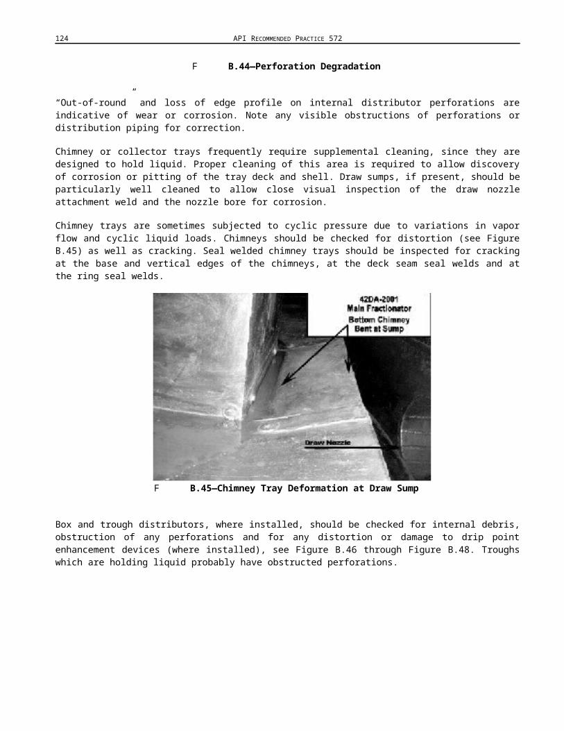
124 API RECOMMENDED PRACTICE 572
F B.84—Tray Fatigue Cracking
Many tray deck materials become embrittled under process conditions (i.e. 410 stainless steel in high-temperature processes). In addition, the vibrations of most modern valve trays may become pronounced under severe operating conditions, leading to cracking of the tray deck at support and stress points (see Figure B.84).
The aligned pinpoint corrosion at the “breakover” work hardened points previously mentioned are such stress points. Cracking of the tray deck is frequently adjacent to internal manway openings. Close visual inspection of these areas after wire brushing may be required to locate cracking.
F B.85—Light-to-moderate Weir Corrosion

INSPECTION PRACTICES FOR PRESSURE VESSELS 125
F B.86—Loose and Missing Hardware Failure
Weirs and downcomer panels of cross flow trays are subject to surface corrosion similar to that experienced by the tray decks (see Figure B.85), without the instances of pooling or puddling of corrosives mentioned above. Most damage or problems with downcomer panels are due to loose or missing hardware. Loose or missing hardware on downcomer anti-jump baffles or downcomer anti-vibration clips are the main point of failure for these tray components.
Most hardware issues on trays result from; mismatched hardware, i.e. carbon steel hardware installed instead of corrosion-resistant alloy hardware, hardware which is loosened due to tray vibration (see Figure B.86), galled stainless steel hardware and improper installation. Inspection for loose hardware and hardware adrift on the tray decks is done by sounding of the tray and downcomer panels with a 4 oz to 6 oz ball peen hammer. When striking individual hardware, efforts should be made to strike the edges of washers as the washers will not gall (also avoids damaging hardware).
Typical torque values for 3/8 in.tray hardware range from 10 ft-lb to 14 ft-lb and 1/2 in. tray hardware torque values range from 18 ft-lb to 22 ft-lb. Figure B.87 and Figure B.88 indicate areas that needed to be properly tightened. Particular attention should be paid to the intended purpose and location of hardware if direct contact with the hammer head is the preferred method of testing.
F B.87—Downcomer and Seal Pan Clamps Loose

126 API RECOMMENDED PRACTICE 572
Tray clamps or clips are friction fittings, as is hardware in a number of other locations on the various types of trays. Movement of the washer/hardware/clip is to be expected. Friction clamps and hardware which do not show movement may have been over tightened.
F B.88—Downcomer Clamp Loose
B Tower Attachments—Tray Support Rings, Support Clips, Downcomer Bars, etc.
Tray support rings are generally constructed of material that matches the shell or cladding material of construction. In towers which are clad with corrosion-resistant alloy material, tray support rings may or may not be constructed of clad material. The carbon steel tray support ring may be welded to the shell with carbon steel weld materials, or may be welded to the cladding itself, utilizing compatible alloy welding rod. In towers constructed of corrosion-resistant alloy materials, carbon steel tray support rings may be welded directly to the shell with compatible corrosion-resistant alloy. Thicknesses vary with ring material, diameter and applied corrosion allowance.
Even with construction drawings and previous reports, direct visual confirmation of support ring attachment configuration may be the only way to ascertain how a particular ring or group of rings are attached. The tops of tray support rings (see Figure B.89), the tray support ring top side fillet welds and the shell in this area are quite often the site of the most aggressive corrosion in a tower (see Figure B.90 and Figure B.91).
F B.89—Tray Support Ring Corroded to Failure
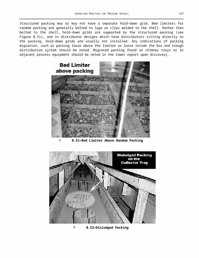
INSPECTION PRACTICES FOR PRESSURE VESSELS 127
The support ring and fillet weld are in the “liquid zone,” yet tray design frequently leaves the circumference of the tray a stagnant area. This allows any process debris and corrosion detritus which is not swept down column by the liquid flow of cross flow trays to collect on top of the ring at the edge of the tray.
F B.90—Deposits Adjacent to Shell are on Ring
F B.91—Shell Corroded to Half Wall Adjacent Top Three Rings
The tray support ring also supply’s a horizontal surface (bound on one side by the shell and on the other side by the tray) for collection or puddling of any corrosives which may have precipitated out of process fluids. Corrosion of this type is often typified by bright orange colored corrosion residue on, and sometimes under the ring (applicable to carbon steel support rings, see Figure B.92).
The area of a carbon steel ring covered by alloy tray decks may corrode under these conditions with little or no visual indications other than the above mentioned orange residue. If inspection of the ring between the tray and the shell shows localized corrosion to be present, consideration to removal of all or part of the tray to allow inspection of the previously covered ring surface, particularly where the possibility of formic acid precipitation exists.

128 API RECOMMENDED PRACTICE 572
F B.92—Support Ring Grooving
Tray support ring upper and lower attachment welds are sometimes subject to localized corrosion in excess of that suffered by the shell or ring (see Figure B.93, Figure B.94, and Figure B.95). This preferential corrosion may be difficult to spot without wire brushing to remove surface debris and process deposits. Stitch welds are sometimes used to attach the lower side of the tray support ring to the shell. Cracking of these stitch welds is common. Careful examination of the stitch welds should be undertaken to ensure no crack propagation into the shell has taken place. Tray support ring butt welds are prone to cracking as well.
F B.93—Cracking of Ring Attachment Weld

INSPECTION PRACTICES FOR PRESSURE VESSELS 129
F B.94—Tray Support Ring Butt Weld Cracking
F B.95—Breeching of the Seal Weld
Propagation of cracking from this source into the shell is possible. When discovered, stop drilling may need to be performed if weld repair is not performed. If indications of corrosion between the shell and ring are present, such as corrosion residue leaking from between the stitch welds, additional NDE such as external UT should be considered. Tray support ring upper attachment welds are prone to cracking, particularly at the ends adjacent downcomers. Careful examination of the welds should be undertaken to ensure no crack propagation into the shell has taken place.
If tray support rings are seal welded, close visual inspection/investigation of all possible breeches of the seal weld should be performed. Breeching of the seal welds may allow process fluids/deposits to accumulate between the ring and shell, leading to localized corrosion of the shell.
Downcomer attachment bars generally show corrosion characteristics similar to that of the shell. Downcomer bars are usually only welded on the outside edge due to the internal angle induced space limitations. The internal angle behind the downcomer bar has the potential to develop contact or crevice corrosion, and is subject to the buildup of possible corrosive deposits. This area may require additional cleaning. Downcomer bar attachment welds are sometimes prone to cracking at the upper and lower ends. Careful examination of the welds should be undertaken to ensure no crack propagation into the shell is present.

130 API RECOMMENDED PRACTICE 572
Support clips and lugs welded to the shell generally show corrosion characteristics similar to that of the shell/head. As with the above tower attachments, cracking of the attachment welds and/or preferential corrosion due to bad welding metallurgy are the primary sources of failure.
B Detecting Surface Corrosion in Towers
Corrosion in towers may be found at virtually every level, at any point of the circumference. The unlined shell may be relatively uncorroded, and removal of identical deposits two trays down will reveal corrosion to 0.060 in.+ general pitting. When necessary, deposits should be removed by hand at a minimum of every other tray.
Shadowing the shell above the top tray, from the bottom head or from the scaffold installed from the bottom head to the bottom tray is the best method of locating corrosion in these areas. The shell inside downcomers is the only location between trays where adequate room for shadowing exists (see Figure B.96 and Figure B.97). This area should be shadowed at every opportunity.
F B.96—Shadowing Inside the Downcomer
F B.97—Shadow the Downcomer Shell Every Tray

INSPECTION PRACTICES FOR PRESSURE VESSELS 131
A(informative)
Sample Record Forms
The inspection record for pressure vessel in service illustrates a form used to store data gathered during the inspection of a pressure vessel in service. Most plants develop a more detailed set of forms that also includes other pertinent data.
The permanent pressure vessel record illustrates a form that is used to record all the basic data of an individual pressure vessel and that becomes the permanent record for that vessel.
The vessel inspection sheet illustrates a form used as a progressive record of thicknesses, from which a corrosion rate can be calculated. Three versions of this form are included. One is blank. The other two show sketches that might be made for different types of pressure vessels. Information on only one pressure vessel should be recorded on any individual copy of this form.
Normally, an inspector would use one copy of this form to record field data, and another copy would become an office record. An inspector might use this form without a sketch when inspecting a vessel for which no basic data is available. In this case, they would make a sketch of the vessel on the form, including all pertinent dimensions and data they can secure in the field.
The record of all pressure vessels on an operating unit illustrates a form used to record and report the actual physical conditions and the allowable operating conditions of all pressure vessel on an operating unit.
The exchanger inspection field datasheet, the exchanger data record, the exchanger inspection report form, the air cooler exchanger inspection report form, and the double-pipe exchanger inspection report form illustrate other forms.
N Computer storage and retrieval of data in a format similar to that of the sample forms is acceptable and may be advantageous in many cases.4
4 The following forms are merely examples for illustration purposes only. (Each company should develop its own approach.) They are not to be considered exclusive or exhaustive in nature. API makes no warranties, express or implied for reliance on or any omissions from the information contained in this document.

132 API RECOMMENDED PRACTICE 572

INSPECTION PRACTICES FOR PRESSURE VESSELS 133

134 API RECOMMENDED PRACTICE 572

INSPECTION PRACTICES FOR PRESSURE VESSELS 135

136 API RECOMMENDED PRACTICE 572

INSPECTION PRACTICES FOR PRESSURE VESSELS 137

138 API RECOMMENDED PRACTICE 572

INSPECTION PRACTICES FOR PRESSURE VESSELS 139

140 API RECOMMENDED PRACTICE 572

INSPECTION PRACTICES FOR PRESSURE VESSELS 141

142 API RECOMMENDED PRACTICE 572

INSPECTION PRACTICES FOR PRESSURE VESSELS 143