mycommittees.api.orgmycommittees.api.org/standards/cre/sci/Documents/RP 577... ·...
156
DRAFT Welding Processes, Inspection, and Metallurgy API RECOMMENDED PRACTICE 577 SECOND EDITION, XXXXX 2012 Page Proof 1--January 19, 2012
Transcript of mycommittees.api.orgmycommittees.api.org/standards/cre/sci/Documents/RP 577... ·...
DRAFT Welding Processes, Inspection, and Metallurgy
API RECOMMENDED PRACTICE 577SECOND EDITION, XXXXX 2012
Page Proof 1--January 19, 2012

DRAFT
Page Proof 1--January 19, 2012
DRAFT Welding Processes, Inspection, and Metallurgy
Downstream Segment
API RECOMMENDED PRACTICE 577SECOND EDITION, XXXX 2012
Page Proof 1--January 19, 2012
DRAFT Special Notes
API publications necessarily address problems of a general nature. With respect to particular circumstances, local,state, and federal laws and regulations should be reviewed.
Neither API nor any of API's employees, subcontractors, consultants, committees, or other assignees make anywarranty or representation, either express or implied, with respect to the accuracy, completeness, or usefulness of theinformation contained herein, or assume any liability or responsibility for any use, or the results of such use, of anyinformation or process disclosed in this publication. Neither API nor any of API's employees, subcontractors,consultants, or other assignees represent that use of this publication would not infringe upon privately owned rights.
API publications may be used by anyone desiring to do so. Every effort has been made by the Institute to assure theaccuracy and reliability of the data contained in them; however, the Institute makes no representation, warranty, orguarantee in connection with this publication and hereby expressly disclaims any liability or responsibility for loss ordamage resulting from its use or for the violation of any authorities having jurisdiction with which this publication mayconflict.
API publications are published to facilitate the broad availability of proven, sound engineering and operatingpractices. These publications are not intended to obviate the need for applying sound engineering judgmentregarding when and where these publications should be utilized. The formulation and publication of API publicationsis not intended in any way to inhibit anyone from using any other practices.
Any manufacturer marking equipment or materials in conformance with the marking requirements of an API standardis solely responsible for complying with all the applicable requirements of that standard. API does not represent,warrant, or guarantee that such products do in fact conform to the applicable API standard.
All rights reserved. No part of this work may be reproduced, translated, stored in a retrieval system, or transmitted by any means, electronic, mechanical, photocopying, recording, or otherwise, without prior written permission from the publisher. Contact the
Publisher, API Publishing Services, 1220 L Street, NW, Washington, DC 20005.
Copyright © 2012 American Petroleum Institute
Page Proof 1--January 19, 2012
DRAFT Foreword
Nothing contained in any API publication is to be construed as granting any right, by implication or otherwise, for themanufacture, sale, or use of any method, apparatus, or product covered by letters patent. Neither should anythingcontained in the publication be construed as insuring anyone against liability for infringement of letters patent.
This document was produced under API standardization procedures that ensure appropriate notification andparticipation in the developmental process and is designated as an API standard. Questions concerning theinterpretation of the content of this publication or comments and questions concerning the procedures under whichthis publication was developed should be directed in writing to the Director of Standards, American PetroleumInstitute, 1220 L Street, NW, Washington, DC 20005. Requests for permission to reproduce or translate all or any partof the material published herein should also be addressed to the director.
Generally, API standards are reviewed and revised, reaffirmed, or withdrawn at least every five years. A one-timeextension of up to two years may be added to this review cycle. Status of the publication can be ascertained from theAPI Standards Department, telephone (202) 682-8000. A catalog of API publications and materials is publishedannually by API, 1220 L Street, NW, Washington, DC 20005.
Suggested revisions are invited and should be submitted to the Standards Department, API, 1220 L Street, NW,Washington, DC 20005, [email protected].
iii
Page Proof 1--January 19, 2012

DRAFT
Page Proof 1--January 19, 2012

DRAFT Contents
Page
Table of Contents will be generated with Final Page Proofs.
v
Page Proof 1--January 19, 2012

DRAFT Page
vi
Page Proof 1--January 19, 2012
DRAFT
1
Welding Processes, Inspection, and Metallurgy
1 Scope
This recommended practice provides guidance to the API authorized inspector on welding inspection as encounteredwith fabrication and repair of refinery and chemical plant equipment and piping. This recommended practice includesdescriptions of common welding processes, welding procedures, welder qualifications, metallurgical effects fromwelding, and inspection techniques to aid the inspector in fulfilling their role implementing API 510, API 570, API 653and API 582. The level of learning and training obtained from this document is not a replacement for the training andexperience required to be a certified welding inspector under one of the established welding certification programssuch as the American Welding Society (AWS) Certified Welding Inspector (CWI), or Canadian and Europeanequivalent schemes such as CWB, CSWIP, PCN, or EFW.
This recommended practice does not require all welds to be inspected; nor does it require welds to be inspected tospecific techniques and extent. Welds selected for inspection, and the appropriate inspection techniques, should bedetermined by the welding inspectors, engineers, or other responsible personnel using the applicable code orstandard. The importance, difficulty, and problems that could be encountered during welding should be considered byall involved. A welding engineer should be consulted on any critical, specialized or complex welding issues.
2 Normative References
The following referenced documents are indispensable for the application of this document. For dated references, only the edition cited applies. For undated references, the latest edition of the referenced document (including any amendments) applies.
API 510, Pressure Vessel Inspection Code: Maintenance, Inspection, Rating, Repair, and Alteration
API 570, Piping Inspection Code: Inspection, Repair, Alteration, and Rerating of In-Service Piping Systems
API Recommended Practice 574, Inspection Practices for Piping System Components
API Recommended Practice 578, Material Verification Program for New and Existing Alloy Piping Systems
API Recommended Practice 582, Recommended Practice and Supplementary Welding Guidelines for the Chemical,Oil, and Gas Industries
API Standard 650, Welded Steel Tanks for Oil Storage
API Standard 653, Tank Inspection, Repair, Alteration, and Reconstruction
API Recommended Practice 2201, Procedures for Welding or Hot Tapping on Equipment in Service
ASME Boiler and Pressure Vessel Code 1
B31.3, Process Piping
Section VIII, Rules for Construction of Pressure Vessels
Section IX, Qualification Standard for Welding and Brazing Procedures, Welders, Brazers, and Welding andBrazing Operators
Section XI, Rules for Inservice Inspection of Nuclear Power Plant Components
Practical Guide to ASME Section IX, Welding Qualifications
1 ASME International, 3 Park Avenue, New York, New York 10016-5990, www.asme.org.
Page Proof 1--January 19, 2012
DRAFT
2 API RECOMMENDED PRACTICE 577
ASNT Central Certification Program CP-189 2, Standard for Qualification and Certification of Nondestructive TestingPersonnel
ASNT Central Certification Program SNT-TC-1A, Personnel Qualification and Certification in Nondestructive Testing
ASTM A10 3, Standard Specification for Seamless Carbon Steel Pipe for High-Temperature Service
ASTM A335, Standard Specification for Seamless Ferritic Alloy-Steel Pipe for High-Temperature Service
ASTM A956, Standard Test Method for Leeb Hardness Testing of Steel Products
ASTM A1038, Standard Practice for Portable Hardness Testing by the Ultrasonic Contact Impedance Method
ASTM E94, Standard Guide for Radiographic Examination
ASTM E1316, Standard Terminology for Nondestructive Examinations
AWS A5.XX 4, Series of Filler Metal Specifications
CASTI 5, Guidebook to ASME Section IX—Welding Qualifications
EN 473 6, Qualification and Certification of NDT Personnel—General Principles
ISO 9712 7, Non-destructive testing—Qualification and certification of personnel
NACE SP 0472 8, Methods and Controls to Prevent In-Service Environmental Cracking of Carbon Steel Weldmentsin Corrosive Refining Environments
WRC Bulletin 342 9, Stainless Steel Weld Metal: Prediction of Ferrite Content
3 Terms, Definitions, and Acronyms
3.1 Terms and Definitions
For the purposes of this document, the following definitions apply.
3.1.1ACFMThe alternating current field measurement (ACFM) method is an electromagnetic inspection technique which can beused to detect and size surface breaking (or in some cases near surface) defects in both magnetic and non-magneticmaterials.
2 American Society for Nondestructive Testing, 1711 Arlingate Lane, P.O. Box 28518, Columbus, Ohio 43228, www.asnt.org.3 ASTM International, 100 Barr Harbor Drive, West Conshohocken, Pennsylvania 19428, www.astm.org.4 American Welding Society, 550 NW LeJeune Road, Miami, Florida 33126, www.aws.org.5 CASTI Publishing, Inc. 10566, 114 Street, Edmontom, Alberta, T5H 3J7, Canada.6 European Committee for Standardization, Avenue Marnix 17, B-1000, Brussels, Belgium, www.cen.eu.7 International Organization for Standardization, 1, ch. de la Voie-Creuse, Case postale 56, CH-1211, Geneva 20, Switzerland,
www.iso.org.8 NACE International (formerly the National Association of Corrosion Engineers), 1440 South Creek Drive, Houston, Texas
77218-8340, www.nace.org.9 The Welding Research Council, 3 Park Avenue, 27th Floor, New York, New York 10016-5902, www.forengineers.org.
Page Proof 1--January 19, 2012
DRAFT
WELDING PROCESSES, INSPECTION, AND METALLURGY 3
3.1.2actual throatThe shortest distance between the weld root and the face of a fillet weld.
3.1.3air carbon arc cutting AACA carbon arc cutting process variation that removes molten metal with a jet of air.
3.1.4arc blowThe deflection of an arc from its normal path because of magnetic forces.
3.1.5arc lengthThe distance from the tip of the welding electrode to the adjacent surface of the weld pool.
3.1.6arc strikeA discontinuity resulting from an arc, consisting of any localized remelted metal, heat-affected metal, or change in thesurface profile of any metal object.
3.1.7arc weldingAWA group of welding processes that produces coalescence of work pieces by heating them with an arc. The processesare used with or without the application of pressure and with or without filler metal.
3.1.8autogenous weldA fusion weld made without filler metal.
3.1.9back-gougingThe removal of weld metal and base metal from the weld root side of a welded joint to facilitate complete fusion andcomplete joint penetration upon subsequent welding from that side.
3.1.10backingA material or device placed against the back-side of the joint, or at both sides of a weld in welding, to support andretain molten weld metal.
3.1.11base metalThe metal to be welded, often called parent metal.
3.1.12bevel angleThe angle between the bevel of a joint member and a plane perpendicular to the surface of the member.
3.1.13burn-throughA term for excessive visible root reinforcement in a joint welded from one side or a hole through the root bead.
Page Proof 1--January 19, 2012
DRAFT
4 API RECOMMENDED PRACTICE 577
3.1.14butteringOne or more layers of deposited weld metal on the face of a weld preparation or surface that will be part of a weldedjoint.
3.1.15constant current power supplyccAn arc welding power source with a volt-ampere relationship yielding a small welding current change from a large arcvoltage change.
3.1.16constant voltage power supplycvAn arc welding power source with a volt-ampere relationship yielding a large welding current change from a smallvoltage change.
3.1.17corrosion specialistA person, acceptable to the owner/user, who has knowledge and experience in corrosion damage mechanisms,metallurgy, materials selection, and corrosion monitoring techniques.
3.1.18crackA fracture type discontinuity characterized by a sharp tip and high ratio of length and width to opening displacement.
3.1.19defectA discontinuity or discontinuities that by nature or accumulated effect render a part or product unable to meetminimum applicable acceptance standards or specifications (e.g. total crack length). The term designates rejectability.
3.1.20direct current electrode negativeDCENThe arrangement of direct current arc welding leads in which the electrode is the negative pole and workpiece is thepositive pole of the welding arc. Commonly known as straight polarity.
3.1.21direct current electrode positiveDCEPThe arrangement of direct current arc welding leads in which the electrode is the positive pole and the work piece isthe negative pole of the welding arc. Commonly known as reverse polarity.
3.1.22discontinuityAn interruption of the typical structure of a material, such as a lack of homogeneity in its mechanical, metallurgical, orphysical characteristics. A discontinuity is not necessarily a defect.
3.1.23distortionThe change in shape or dimensions, temporary or permanent, of a part as a result of heating or welding.
Page Proof 1--January 19, 2012
DRAFT
WELDING PROCESSES, INSPECTION, AND METALLURGY 5
3.1.24Eddy current examination techniqueETAn inspection method that applies primarily to non-ferromagnetic materials.
3.1.25examinerA person who assists the inspector by performing specific nondestructive examination (NDE) on components butdoes not evaluate the results of those examinations in accordance with the appropriate inspection Code, unlessspecifically trained and authorized to do so by the owner or user
3.1.26filler metalThe metal or alloy to be added in making a welded joint.
3.1.27fillet weld sizeFor equal leg fillet welds, the leg lengths of the largest isosceles right triangle that can be inscribed within the filletweld cross section.
3.1.28fusion lineThe interface between the base and weld metal.
3.1.29groove angleThe total included angle of the groove between work pieces.
3.1.30heat affected zoneHAZThe portion of the base metal whose mechanical properties or microstructure have been altered by the heat ofwelding or thermal cutting.
3.1.31heat inputThe energy supplied by the welding arc to the work piece. Heat input is calculated as follows: heat input = (V × i × 60) / (1000 × v) in kJ/in., where V = voltage, i = amperage, v = weld travel speed (in./min).
3.1.32hot crackingCracking formed at temperatures near the completion of solidification.
3.1.33inclusionEntrapped foreign solid material, such as slag, flux, tungsten, or oxide.
3.1.34incomplete fusionA weld discontinuity in which complete coalescence did not occur between weld metal and fusion faces or adjoiningweld beads.
Page Proof 1--January 19, 2012
DRAFT
6 API RECOMMENDED PRACTICE 577
3.1.35incomplete joint penetrationA joint root condition in a groove weld in which weld metal does not extend through the joint thickness.
3.1.36indicationA signal of discontinuity in the material under nondestructive examination.
3.1.37inspectorAn individual who is qualified and certified to perform inspections under the proper inspection code or who holds avalid and current National Board Commission.
3.1.38interpass temperature, weldingIn multipass weld, the lowest temperature of the deposited weld metal before the next weld pass is started.
3.1.39IQIImage quality indicator “Penetrameter” is another common term for IQI.
3.1.40joint penetrationThe distance the weld metal extends from the weld face into a joint, exclusive of weld reinforcement.
3.1.41joint typeA weld joint classification based on five basic joint configurations such as a butt joint, corner joint, edge joint, lap joint,and t-joint.
3.1.42lack of fusionLOFA non-standard term indicating a weld discontinuity in which fusion did not occur between weld metal and fusion facesor adjoining weld beads.
3.1.43lamellar tearA subsurface terrace and step-like crack in the base metal with a basic orientation parallel to the wrought surfacecaused by tensile stresses in the through-thickness direction of the base metal weakened by the presence of smalldispersed, planar shaped, nonmetallic inclusions parallel to the metal surface.
3.1.44laminationA type of discontinuity with separation or weakness generally aligned parallel to the worked surface of a metal.
3.1.45linear discontinuityA discontinuity with a length that is substantially greater than its width.
3.1.46longitudinal crackA crack with its major axis orientation approximately parallel to the weld axis.
Page Proof 1--January 19, 2012
DRAFT
WELDING PROCESSES, INSPECTION, AND METALLURGY 7
3.1.47nondestructive examinationNDEThe act of determining the suitability of some material or component for its intended purpose using techniques that donot affect its serviceability.
3.1.48overlapThe protrusion of weld metal beyond the weld toe or weld root.
3.1.49oxyacetylene cuttingOFAAn oxygen fuel gas cutting process variation that uses acetylene as the fuel gas.
3.1.50peeningThe mechanical working of metals using impact blows.
3.1.51penetrameterOld terminology for IQI still in use today but not recognized by the codes and standards.
3.1.52porosityCavity-type discontinuities formed by gas entrapment during solidification or in thermal spray deposit.
3.1.53positive material identification testingPMI testingAny physical evaluation or test of a material to confirm that the material which has been or will be placed into serviceis consistent with the selected or specified alloy material designated by the owner/user.
3.1.54preheatMetal temperature value achieved in a base metal or substrate prior to initiating the thermal operations. Also equal tothe minimum interpass temperature.
3.1.55procedure qualification recordPQRA record of the welding data and variables used to weld a test coupon and the test results used to qualify the weldingprocedure.
3.1.56recordable indicationRecording on a data sheet of an indication or condition that does not necessarily exceed the rejection criteria but interms of code, contract or procedure will be documented.
3.1.57reportable indicationRecording on a data sheet of an indication that exceeds the reject flaw size criteria and needs not onlydocumentation, but also notification to the appropriate authority to be corrected. All reportable indications arerecordable indications but not vice-versa.
Page Proof 1--January 19, 2012
DRAFT
8 API RECOMMENDED PRACTICE 577
3.1.58root faceThe portion of the groove face within the joint root.
3.1.59root openingA separation or gap at the joint root between the work pieces.
3.1.60shielding gasProtective gas used to prevent or reduce atmospheric contamination.
3.1.61slagA nonmetallic product resulting from the mutual dissolution of flux and nonmetallic impurities in some welding andbrazing processes.
3.1.62slag inclusionA discontinuity consisting of slag entrapped in the weld metal or at the weld interface.
3.1.63spatterThe metal particles expelled during fusion welding that do not form a part of the weld.
3.1.64tack weldA weld made to hold the parts of a weldment in proper alignment until the final welds are made.
3.1.65temper bead weldingA welding technique where the heat and placement of weld passes in deposited weld layers is controlled so thatsufficient heat is provided to temper each previously deposited weld layer.
3.1.66throat theoreticalThe distance from the beginning of the joint root perpendicular to the hypotenuse of the largest right triangle that canbe inscribed within the cross-section of a fillet weld. This dimension is based on the assumption that the root openingis equal to zero
3.1.67transverse crackA crack with its major axis oriented approximately perpendicular to the weld axis.
3.1.68travel angleThe angle less than 90 degrees between the electrode axis and a line perpendicular to the weld axis, in a planedetermined by the electrode axis and the weld axis.
3.1.69tungsten inclusionA discontinuity consisting of tungsten entrapped in weld metal.
Page Proof 1--January 19, 2012
DRAFT
WELDING PROCESSES, INSPECTION, AND METALLURGY 9
3.1.70undercutA groove melted into the base metal adjacent to the weld toe or weld root and left unfilled by weld metal.
3.1.71underfillA condition in which the weld joint is incompletely filled when compared to the intended design.
3.1.72welderA person who performs a manual or semiautomatic welding operation.
3.1.73welder certificationWritten verification that a welder has produced welds meeting a prescribed standard of welder performance.
3.1.74welder performance qualificationWPQA test administered to a welder to demonstrate the welder’s ability to produce welds meeting prescribed standards.Welding performance qualification tests are specific to a WPS.
3.1.75weldingA joining process that produces coalescence of base metals by heating them to the welding temperature, with orwithout the application of pressure or by the application of pressure alone, and with or without the use of filler metal.
3.1.76welding engineerAn individual who holds an engineering degree and is knowledgeable and experienced in the engineering disciplinesassociated with welding.
3.1.77welding operatorA person who operates automatic welding equipment.
3.1.78welding procedure specificationWPSA document that describes how welding is to be carried out in production.
3.1.79weldmentAn assembly whose component parts are joined by welding.
3.1.80weld jointThe junction of members or the edges of members which are to be joined or have been joined by welding.
3.1.81weld reinforcementWeld metal in excess of the quantity required to fill a joint.
Page Proof 1--January 19, 2012
DRAFT
10 API RECOMMENDED PRACTICE 577
3.1.82weld toeThe junction of the weld face and the base metal.
3.1.83wet fluorescent magnetic-particle examination techniqueWFMTThis inspection method is suitable for magnetic materials.
3.2 Acronyms
LT leak examination technique
MT magnetic Particle examination technique
PT penetrant examination technique.
RT radiographic examination technique.
VT visual examination technique.
4 Welding Inspection
4.1 General
Welding inspection is a critical part of an overall weld quality assurance program. Welding inspection includes muchmore than just the non-destructive examination of the completed weld. Many other issues are important, such asreview of specifications, joint design, cleaning procedures, and welding procedures. Welder qualifications should beperformed to better assure the weldment performs properly in service.
Welding inspection activities can be separated into three stages corresponding to the welding work process.Inspectors should perform specific tasks prior to welding, during welding and upon completion of welding, although itis usually not necessary to inspect every weld.
4.2 Tasks Prior to Welding
The importance of tasks in the planning and weld preparation stage should not be understated. Many weldingproblems can be avoided during this stage when it is easier to make changes and corrections, rather than after thewelding is in progress or completed. Such tasks may include.
4.2.1 Drawings, Codes, and Standards
Review drawings, standards, codes, and specifications to both understand the requirements for the weldment and identify any inconsistencies.
4.2.1.1 Quality Control Items To Assess
[needs lead-in paragraph]
a) Welding symbols and weld sizes clearly specified (see Annex A).
b) Weld joint designs and dimensions clearly specified (see Annex A).
c) Weld maps identify the welding procedure specification (WPS) to be used for specific weld joints.
d) Dimensions detailed and potential for distortion addressed.
Page Proof 1--January 19, 2012
DRAFT
WELDING PROCESSES, INSPECTION, AND METALLURGY 11
e) Welding consumables specified (see 7.3, 7.4, 7.6, and Annex D).
f) Proper handling of consumables, if any, identified (see 7.7).
g) Base material requirements specified (such as the use of impact tested materials where notch ductility is arequirement in low temperature service).
h) Mechanical properties and required testing identified (see 10.4).
i) Weather protection and wind break requirements defined.
j) Preheat requirements and acceptable preheat methods defined (see 10.5).
k) Postweld heat treatment (PWHT) requirements and acceptable PWHT method defined (see 10.6).
l) Inspection hold-points and NDE requirements defined (see Section 9).
m) Additional requirements, such as production weld coupons, clearly specified.
n) Pressure testing requirements, if any, clearly specified (see 9.11).
4.2.1.2 Potential Inspector Actions
[needs lead-in paragraph]
a) Identify and clarify missing details and information.
b) Identify and clarify missing weld sizes, dimensions, tests, and any additional requirements.
c) Identify and clarify inconsistencies with standards, codes, and specification requirements.
d) Highlight potential weld problems not addressed in the design.
e) Establish applicable accept/reject criteria.
f) Verify that the appropriate degree of NDE has been specified.
4.2.2 Weldment Requirements
Review requirements for the weldment with the personnel involved with executing the work such as the designengineer, welding engineer, welding organization and inspection organization.
4.2.2.1 Quality Control Items To Assess
[needs lead-in paragraph]
a) Competency of welding organization to perform welding activities in accordance with codes, standards, andspecifications.
b) Competency of inspection organization to perform specified inspection tasks.
c) Roles and responsibilities of engineers, welding organization, and welding inspectors defined and appropriate forthe work.
Page Proof 1--January 19, 2012
DRAFT
12 API RECOMMENDED PRACTICE 577
d) Independence of the inspection organization from the production organization is clear and demonstrated.
e) Competency of welding organization to perform welder/welding operator qualifications.
4.2.2.2 Potential Inspector Action
Highlight deficiencies and concerns with the organizations to appropriate personnel.
4.2.3 Procedures and Qualification Records
Review the WPS(s) and welder performance qualification record(s) (WPQ) to assure they are acceptable for thework.
4.2.3.1 Quality Control Items To Assess
[needs lead-in paragraph]
a) WPS(s), including those developed for making repairs, are properly qualified and meet applicable codes,standards and specifications for the work (see 6.4).
b) Procedure qualification records (PQR) are properly performed and support the WPS(s) (see 6.4).
c) Welder performance qualifications (WPQ) meet requirements for the WPS (see 8.3).
4.2.3.2 Potential Inspector Actions
[needs lead-in paragraph]
a) Obtain acceptable WPS(s) and PQR(s) for the work.
b) Qualify WPS(s) where required and witness qualification effort.
c) Qualify or re-qualify welders where required and witness a percentage of the welder qualifications.
4.2.4 NDE Information
Confirm the NDE examiner(s), NDE procedure(s) and NDE equipment of the inspection organization are acceptablefor the work.
4.2.4.1 Quality Control Items To Assess
[needs lead-in paragraph]
a) NDE examiners are properly certified for the NDE technique (see 4.6).
b) NDE procedures are current and accurate.
c) Calibration of NDE equipment is current.
d) NDE procedures and techniques specified are capable of achieving the required acceptance/rejectionrequirements.
Page Proof 1--January 19, 2012
DRAFT
WELDING PROCESSES, INSPECTION, AND METALLURGY 13
4.2.4.2 Potential Inspector Actions
[needs lead-in paragraph]
a) Identify and correct deficiencies in certifications and procedures.
b) Obtain calibrated equipment.
4.2.5 Welding Equipment and Instruments
Confirm welding equipment and instruments are calibrated and operable.
4.2.5.1 Quality Control Items To Assess
[needs lead-in paragraph]
a) Welding machine calibration is current.
b) Instruments such as ammeters, voltmeters, contact pyrometers, have current calibrations.
c) Storage ovens for welding consumables operate with automatic heat control and visible temperature indication.
4.2.5.2 Potential Inspector Actions
[needs lead-in paragraph]
a) Confirm recalibration of equipment and instruments.
b) Confirm replacement of defective equipment and instruments.
4.2.6 Heat Treatment and Pressure Testing
Confirm heat treatment and pressure testing procedures and associated equipment are acceptable.
4.2.6.1 Quality Control Items To Assess
[needs lead-in paragraph]
a) Heat treatment procedure is available and appropriate (see 10.6).
b) Pressure testing procedures are available and detail test requirements (see 9.11).
c) PWHT equipment calibration is current.
d) Pressure testing equipment and gauges calibrated and meet appropriate test requirements.
4.2.6.2 Potential Inspector Actions
[needs lead-in paragraph]
a) Identify and correct deficiencies in procedures.
b) Obtain calibrated equipment.
Page Proof 1--January 19, 2012
DRAFT
14 API RECOMMENDED PRACTICE 577
4.2.7 Materials
Ensure all filler metals, base materials, and backing ring materials are properly marked and identified and if required,perform PMI to verify the material composition.
4.2.7.1 Quality Control Items To Assess
[needs lead-in paragraph]
a) Material test certifications are available and items properly marked (including backup ring if used; see 10.8).
b) Electrode marking, bare wire flag tags, identification on spools of wire, etc. as-specified (see 9.2).
c) Filler material markings are traceable to a filler material certification.
d) Base metal markings are traceable to a material certification.
e) Recording of filler and base metal traceability information is performed.
f) Base metal stampings are low stress and not detrimental to the component.
g) Paint striping color code is correct for the material of construction.
h) PMI records supplement the material traceability and confirm the material of construction (see 9.2).
4.2.7.2 Potential Inspector Actions
[needs lead-in paragraph]
a) Reject non-traceable or improperly marked materials.
b) Reject inappropriate materials.
4.2.8 Weld Preparation
Confirm weld preparation, joint fit-up, and dimensions are acceptable and correct.
4.2.8.1 Quality Control Items To Assess
[needs lead-in paragraph]
a) Weld preparation surfaces are free of contaminants and base metal defects such as laminations and cracks.
b) Preheat, if required, applied for thermal cutting.
c) Hydrogen bake-out heat treatment, if required, performed to procedure.
d) Weld joint is free from oxide and sulfide scales, hydrocarbon residue, and any excessive build-up of weld-throughprimers.
e) Weld joint type, bevel angle, root face, and root opening are correct.
f) Alignment and mismatch is correct and acceptable.
Page Proof 1--January 19, 2012
DRAFT
WELDING PROCESSES, INSPECTION, AND METALLURGY 15
g) Dimensions of base materials, filler metal, and weld joint are correct.
h) Piping socket welds have proper gap.
4.2.8.2 Potential Inspector Action
Reject material or correct deficiencies.
4.2.9 Preheat
Confirm the preheat equipment and temperature.
4.2.9.1 Quality Control Items To Assess
[needs lead-in paragraph]
a) Preheat equipment and technique are acceptable.
b) Preheat coverage and temperature are correct (see 10.5).
c) Reheat, if required, applied to thermal cutting operations.
d) Preheat, if required, applied to remove moisture.
4.2.9.2 Potential Inspector Action
Identify and correct deficiencies in the preheat operations.
4.2.10 Welding Consumables
Confirm electrode, filler wire, fluxes, and inert gases are as specified and acceptable.
4.2.10.1 Quality Control Items To Assess
[needs lead-in paragraph]
a) Filler metal type and size are correct per procedure.
b) Filler metals are being properly handled and stored (see 7.7).
c) Filler metals are clean and free of contaminants.
d) Coating on coated electrodes is neither damaged nor wet.
e) Flux is appropriate for the welding process and being properly handled.
f) Inert gases, if required are appropriate for shielding and purging.
g) Gas composition is correct and meets purity requirements.
h) Shielding gas and purging manifold systems are periodically bled to prevent back filling with air.
Page Proof 1--January 19, 2012
DRAFT
16 API RECOMMENDED PRACTICE 577
4.2.10.2 Potential Inspector Actions
[needs lead-in paragraph]
a) Reject inappropriate materials.
b) Identify and correct deficiencies.
4.3 Tasks During Welding Operations
Welding inspection during welding operations should include audit parameters to verify the welding is performed tothe procedures. Such tasks may include the following.
4.3.1 Quality Assurance
Establish a quality assurance and quality control audit procedure with the welding organization.
4.3.1.1 Quality Control Items To Assess
[needs lead-in paragraph]
a) Welder is responsible for quality craftsmanship of weldments.
b) Welder meets qualification requirements.
c) Welder understands welding procedure and requirements for the work.
d) Special training and mock-up weldments performed if required.
e) Welder understands the inspection hold-points.
4.3.1.2 Potential Inspector Actions
[needs lead-in paragraph]
a) Review welder performance with welding organization.
b) See Annex B.
4.3.2 Welding Parameters and Techniques
Confirm welding parameters and techniques are supported by the WPS and WPQ.
4.3.2.1 Quality Control Items To Assess
[needs lead-in paragraph]
a) Essential variables are being met during welding.
1) Filler material, fluxes, and inert gas composition/flow rate.
2) Purge technique, flow rate, O2 analysis, etc.
Page Proof 1--January 19, 2012
DRAFT
WELDING PROCESSES, INSPECTION, AND METALLURGY 17
3) Rod warmers energized or where rod warmers are not employed, the welder complies with maximum exposuretimes out of the electrode oven.
4) Preheating during tack welding and tack welds removed (if required).
5) Welding technique, weld progression, bead overlap, etc.
6) Equipment settings such as amps, volts, and wire feed.
7) Preheat and interpass temperatures. As detailed in API 582, the maximum interpass temperature should bespecified for austenitic stainless steels, duplex stainless steels, and non-ferrous alloys (i.e. Type-300 stainlesssteels). The maximum interpass temperature should also be specified for carbon/low alloy steels that requireimpact testing.
8) Travel speed (key element in heat input).
9) Heat input (where appropriate).
b) Mock-up weldment which simulates the production weld joint, meets requirements of the welding engineer and isused to demonstrate welder capability or weld procedure parameters as required.
c) Welder adheres to good welding practices.
4.3.2.2 Potential Inspector Actions
[needs lead-in paragraph]
a) Review mock-up weldment problems with welding engineer.
b) Review weld quality with welding organization.
c) See Annex B.
4.3.3 Weldment Examination
Complete physical checks, visual examination, and in-process NDE.
4.3.3.1 Quality Control Items To Assess
[needs lead-in paragraph]
a) Tack welds to be incorporated in the weld are of acceptable quality.
b) Weld root has adequate penetration and quality.
c) Cleaning between weld passes and of back-gouged surfaces is acceptable.
d) Additional NDE performed between weld passes and on back-gouged surfaces shows acceptable results.
e) In-process rework and defect removal is accomplished.
f) In-process ferrite measurement, if required, is performed and recorded.
g) Final weld reinforcement and fillet weld size meets work specifications and drawings.
Page Proof 1--January 19, 2012
DRAFT
18 API RECOMMENDED PRACTICE 577
4.3.3.2 Potential Inspector Action
Reject unacceptable workmanship.
4.4 Tasks Upon Completion of Welding
Final tasks upon completion of the weldment and work should include those that assure final weld quality beforeplacing the weldment in service.
4.4.1 Appearance and Finish
Verify postweld acceptance, appearance and finishing of the welded joints.
4.4.1.1 Quality Control Items To Assess
[needs lead-in paragraph]
a) Size, length and location of all welds conform to the drawings/specifications/code.
b) No welds added without approval.
c) Dimensional and visual checks of the weld don’t identify welding discontinuities, excessive distortion, and poorworkmanship.
d) Temporary attachments and attachment welds removed and blended with base metal.
e) Discontinuities reviewed against acceptance criteria for defect classification.
f) PMI of the weld, if required, indicating compliance with the specification.
g) Welder stamping/marking of welds confirmed.
h) Perform field hardness check (see 9.10).
4.4.1.2 Potential Inspector Actions
Inspect rework of existing welds, removal of welds and weld repairs made as required.
4.4.2 NDE Review
Verify NDE is performed at selected locations and review examiner’s findings.
4.4.2.1 Quality Control Items To Assess
[needs lead-in paragraph]
a) Specified locations examined.
b) Specified frequency of examination.
c) NDE performed after final PWHT.
d) Work of each welder included in random examination techniques.
Page Proof 1--January 19, 2012
DRAFT
WELDING PROCESSES, INSPECTION, AND METALLURGY 19
e) RT film quality, IQI placement, IQI visibility, etc. complies with standards.
f) Inspector is in agreement with examiners interpretations and findings.
g) Documentation for all NDE correctly executed (see Section 9.11).
4.4.2.2 Potential Inspector Actions
[needs lead-in paragraph]
a) Require additional NDE to address deficiencies in findings.
b) Check joints for delayed cracking of thick section, highly constrained and high strength material joining.
c) Repeat missing or unacceptable examinations.
d) Correct discrepancies in examination records.
4.4.3 Postweld Heat Treatment
Verify postweld heat treatment is performed to the procedure and produces acceptable results.
4.4.3.1 Quality Control Items To Assess
[needs lead-in paragraph]
a) Paint marking and other detrimental contamination removed.
b) Temporary attachments removed.
c) Machined surfaces protected from oxidation.
d) Equipment internals, such as valve internals, removed to prevent damage.
e) Equipment supported to prevent distortion.
f) Thermocouples fastened properly.
g) Thermocouples adequately monitor the different temperature zones and thickest/thinnest parts in the fabrication.
h) Temperature monitoring system calibrated.
i) Local heating bandwidth is adequate.
j) Insulation applied to the component where required for local heating.
k) Temperature and hold time are correct.
l) Heating rate and cooling rate are correct.
m) Distortion is acceptable after completion of the thermal cycle.
n) Hardness indicates an acceptable heat treatment (see 10.7).
Page Proof 1--January 19, 2012
DRAFT
20 API RECOMMENDED PRACTICE 577
4.4.3.2 Potential Inspector Actions
[needs lead-in paragraph]
a) Calibrate temperature-monitoring equipment.
b) Correct deficiencies before heat treatment.
c) Repeat the heat treatment cycle.
4.4.4 Pressure Testing
Verify pressure test is performed to the procedure.
4.4.4.1 Quality Control Items To Assess
[needs lead-in paragraph]
a) Pressure meets test specification.
b) Test duration is as-specified.
c) Metal temperature of component meets minimum and maximum requirements.
d) Pressure drop or decay is acceptable per procedure.
e) Visual examination does not reveal defects.
4.4.4.2 Potential Inspector Actions
[needs lead-in paragraph]
a) Either correct deficiencies prior to or during pressure test as appropriate.
b) Repeat test as necessary.
c) Approve repair plan if defects are identified.
4.4.5 Documentation Audit
Perform a final audit of the inspection dossier to identify inaccuracies and incomplete information.
4.4.5.1 Quality Control Items To Assess
[needs lead-in paragraph]
a) All verifications in the quality plan were properly executed.
b) Inspection reports are complete, accepted and signed by responsible parties.
c) Inspection reports, NDE examiners interpretations and findings are accurate (see 9.11).
Page Proof 1--January 19, 2012
DRAFT
WELDING PROCESSES, INSPECTION, AND METALLURGY 21
4.4.5.2 Potential Inspector Actions
[needs lead-in paragraph]
a) Require additional inspection verifications to address deficiencies in findings.
b) Repeat missing or unacceptable examinations.
c) Correct discrepancies in examination records.
4.5 Non-Conformances and Defects
4.5.1 General
At any time during the welding inspection, if defects or non-conformances to the specification are identified, theyshould be brought to the attention of those responsible for the work or corrected before welding proceeds further.Defects should be completely removed and re-inspected following the same tasks outlined in this section until theweld is found to be acceptable. Corrective action for a non-conformance will depend upon the nature of the non-conformance and its impact on the properties of the weldment. Corrective action may include reworking the weld. See9.1 for common types of discontinuities or flaws that can lead to defects or non-conformances.
4.5.2 Repair Welds
When inspection identifies a rejectable defect, the inspector should mark the area for repair, the defect should beremoved, and any necessary repair welding performed. Any repair welding should be performed according to aprocedure accepted by the inspector or engineer. After the repair, the weld should be reinspected. If the inspectionindicates that the repair is acceptable, no further action is taken, and the equipment/piping is placed into service. If theinspection indicates that the defect was not removed or that a new defect is present, the repair weld is rejected and asecond repair is undertaken. After the second unsuccessful attempt at weld repair, the inspector and/or weldingengineer should evaluate reason for the inadequacy of the weld repair.
There are many factors that come into play when trying to determine the number of times a welded joint cancontinuously be repaired before a complete cut-out of the weld is required such as: base metal material, complexity ofthe weld configuration/position (e.g. furnace tubes or boiler tubes), or size of the weld. The welding engineer orinspector should be notified when a weld has failed a weld quality test more than three times to help determine thecause(s) of the defect(s) and the appropriate path forward.
4.6 NDE Examiner Certification
4.6.1 The referencing codes or standards may require the examiner be qualified in accordance with a specific codeand certified as meeting the requirements. Typically weld construction standards such as ASME for pressure vesselsor piping, and API 510 for in-service pressure vessel examination reference ASME Section V, Article 1, which whenspecified by the referencing code, requires NDE personnel be qualified with one of the following:
a) ASNT SNT-TC-1A,
b) ANSI/ASNT CP-189.
These references give the employer guidelines (SNT-TC-1A) or standards (CP-189) for the certification of NDEinspection personnel. They also require the employer to develop and establish a written practice or procedure thatdetails the employer’s requirements for certification of inspection personnel. It typically includes the training, andexperience prerequisites prior to certification, and recertification requirements. A certification scheme in accordancewith ISO 9712 may be specified for international work. ISO 9712 outlines certification quidelines generally organizedunder a national scheme and vested in the individual. In the USA the scheme is managed by ASNT as the ACCP
Page Proof 1--January 19, 2012
DRAFT
22 API RECOMMENDED PRACTICE 577
(ASNT Central Certification Program). Although an Inspection company’s Written Practice may allow the employer toappoint a Level III, the owner user may prefer that, at least for initial certification, a Level III Examiner be certified byexamination.
4.6.2 If the referencing code does not list a specific standard to be qualified against, qualification may involvedemonstration of competency by the personnel performing the examination or other requirements specified by theowner-user. The API in-service inspection documents go further than this and for a number of specific circumstancessuch as fitness-for-service (FFS) and welds not subject to hydrotest may require the use of personnel who havepassed a performance demonstration test such as (e.g. the API QUTE or owner-user accepted equivalent).
4.6.3 Equivalency is determined by the relevant API committee and is posted on the API website. In general it isdefined as:
Ultrasonic Shear Wave Operators should be subject to a performance demonstration test that should meet or exceedas a minimum the test protocols, criteria and passing scores described as follows.
a) The test should be administered either by the owner-user or an independent third party as designated by theowner-user. All testing protocols including design, manufacture, and verification of test samples should bedocumented and retained under close limited supervision to ensure the test protocols remain confidential.
b) Candidates prior to performance testing should demonstrate training and certification to a national or internationalcertification scheme acceptable to the owner-user (for guidance SNT-TC-1A, CP-189, EN473, or ISO 9712).
c) Candidates should be provided with a written outline protocol which they should read and acknowledge prior tocommencement of the test.
d) As a minimum the test should comprise:
1) Carbon Steel (P1) Plates 1/2 in. (12 mm) and 1 in. (25 mm) thick with a weld single or double ‘V’ weld prep.
2) Two carbon Steel (P1) Pipes 12 in. (300 mm) and 8 in. (200 mm) NPS, in the wall thickness range 1/2 in. to 3/4 in.(12 mm to 17 mm).
3) The samples will provide a weld length such that the total weld length examined by the candidate should not beless than 77 in. (1956 mm) in total.
4) The total weld length should include a number of individual flaws simulating the following typical weldimperfections:
i) lack of side wall fusion;
ii) lack of root fusion;
iii) linear inclusions (slag);
iv) cracks;
v) porosity.
e) Flaws should be designed and placed so as to determine the candidate’s ability to detect and characterize a flaw,and to accurately locate the flaw in relationship to the weld. Also, the individual should demonstrate the ability todiscern geometric indications like mismatch and weld root from actual flaws.
Page Proof 1--January 19, 2012
DRAFT
WELDING PROCESSES, INSPECTION, AND METALLURGY 23
4.6.4 In order to be successful in the test, candidates should detect, characterize and locate 80 % of the knownflaws in the weld sections they have been requested to examine. Candidates who make more than 20 % overcalls i.e.misinterpreting a geometric reflector as a flaw should not be deemed to have passed the test.
4.6.5 Candidates should be advised if they have passed or failed the test. No other data should be made availablein order to ensure the confidentiality of data relating to flaw, numbers, locations, types, and sizes.
4.6.6 The approval test should typically be valid for a period of three years after which the candidate should beretested. If at any time the performance of an operator is called into question, the operator may be re-tested at theowner-users discretion.
4.6.7 Approval of any candidate under this protocol is restricted to the specific owner-user administering the testand it should be utilized for compliance with the referenced paragraphs in API 510 and API 570 and should not bedeemed as an API certification or endorsement in any form.
4.7 Safety Precautions
Inspectors should be aware of the hazards associated with welding and take appropriate steps to prevent injury whileperforming inspection tasks. As a minimum, the site’s safety rules and regulations should be reviewed as applicableto welding operations. Hazards that the inspector would more commonly encounter in the presence of weldinginclude arc radiation, air contamination, airborne debris, tripping hazards (cables), and heat. The arc is a source ofvisible, ultraviolet and infrared light. As such, eye protection using proper filters and proper clothing to cover the skinshould be used. Proper ventilation is necessary to remove air-borne particulates, which include vaporized metals. Inareas of inadequate ventilation, filtered breathing protection may be required. The use of gas-shielded processes inconfined spaces can create an oxygen deficient environment. Ventilation practice in these instances should becarefully reviewed. Welding can produce sparks and other air-borne debris that can burn the eyes. Appropriateprecautions are necessary.
5 Welding Processes
5.1 General
The inspector should understand the basic arc welding processes most frequently used in the fabrication and repair ofrefinery and chemical process equipment. These processes include shielded metal arc welding (SMAW), gastungsten arc welding (GTAW), gas metal arc welding (GMAW), flux cored arc welding (FCAW), submerged arcwelding (SAW), and stud arc welding (SW). Descriptions of less frequently used welding process are available in thereferenced material. Each process has advantages and limitations depending upon the application and can be moreor less prone to particular types of discontinuities.
5.2 Shielded Metal Arc Welding (SMAW)
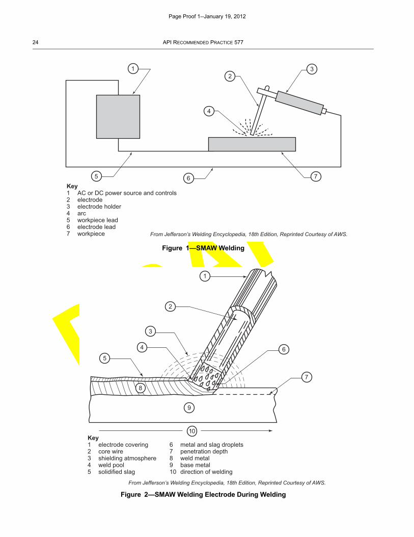
SMAW is the most widely used of the various arc welding processes. SMAW uses an arc between a coveredelectrode and the weld pool. It employs the heat of the arc, coming from the tip of a consumable covered electrode, tomelt the base metal. Shielding is provided from the decomposition of the electrode covering, without the application ofpressure and with filler metal from the electrode. Either alternating current (ac) or direct current (dc) may beemployed, depending on the welding power supply and the electrode selected. A constant-current (CC) power supplyis preferred. SMAW is a manual welding process. See Figure 1 and Figure 2 for schematics of the SMAW circuit andwelding process.
Page Proof 1--January 19, 2012
DRAFT
24 API RECOMMENDED PRACTICE 577
Figure 1—SMAW Welding
Figure 2—SMAW Welding Electrode During Welding
From Jefferson’s Welding Encyclopedia, 18th Edition, Reprinted Courtesy of AWS.
Key1 AC or DC power source and controls2 electrode3 electrode holder4 arc5 workpiece lead6 electrode lead7 workpiece
1
5
2
4
3
6 7
From Jefferson’s Welding Encyclopedia, 18th Edition, Reprinted Courtesy of AWS.
Key1 electrode covering2 core wire3 shielding atmosphere4 weld pool5 solidified slag
6 metal and slag droplets7 penetration depth8 weld metal9 base metal10 direction of welding
1
2
3
4
56
7
8
9
10
Page Proof 1--January 19, 2012

DRAFT
WELDING PROCESSES, INSPECTION, AND METALLURGY 25
5.2.1 Electrode Covering
Depending on the type of electrode being used, the covering performs one or more of the following functions.
a) Provides a gas to shield the arc and prevent excessive atmospheric contamination of the molten filler metal.
b) Provides scavengers, deoxidizers, and fluxing agents to cleanse the weld and prevent excessive grain growth inthe weld metal.
c) Establishes the electrical characteristics of the electrode, stabilizes the welding arc and influences operability invarious welding positions.
d) Provides a slag blanket to protect the hot weld metal from the air and enhances the mechanical properties, beadshape, and surface cleanliness of the weld metal.
e) Provides a means of adding alloying elements to produce appropriate weld metal chemistry, mechanicalproperties and increase deposition efficiency.
5.2.2 Advantages of SMAW
Some commonly accepted advantages of the SMAW process include:
a) Equipment is relatively simple, inexpensive, and portable.
b) Process can be used in areas of limited access.
c) Process is less sensitive to wind and draft than other welding processes.
d) Process is suitable for most of the commonly used metals and alloys.
5.2.3 Limitations of SMAW
Limitations associated with SMAW are:
a) Deposition rates are lower than for other processes such as GMAW.
b) Slag usually must be removed from every deposited weld pass, at stops and starts, and before depositing a weldbead adjacent to or onto a previously deposited weld bead.
5.3 Gas Tungsten Arc Welding (GTAW)
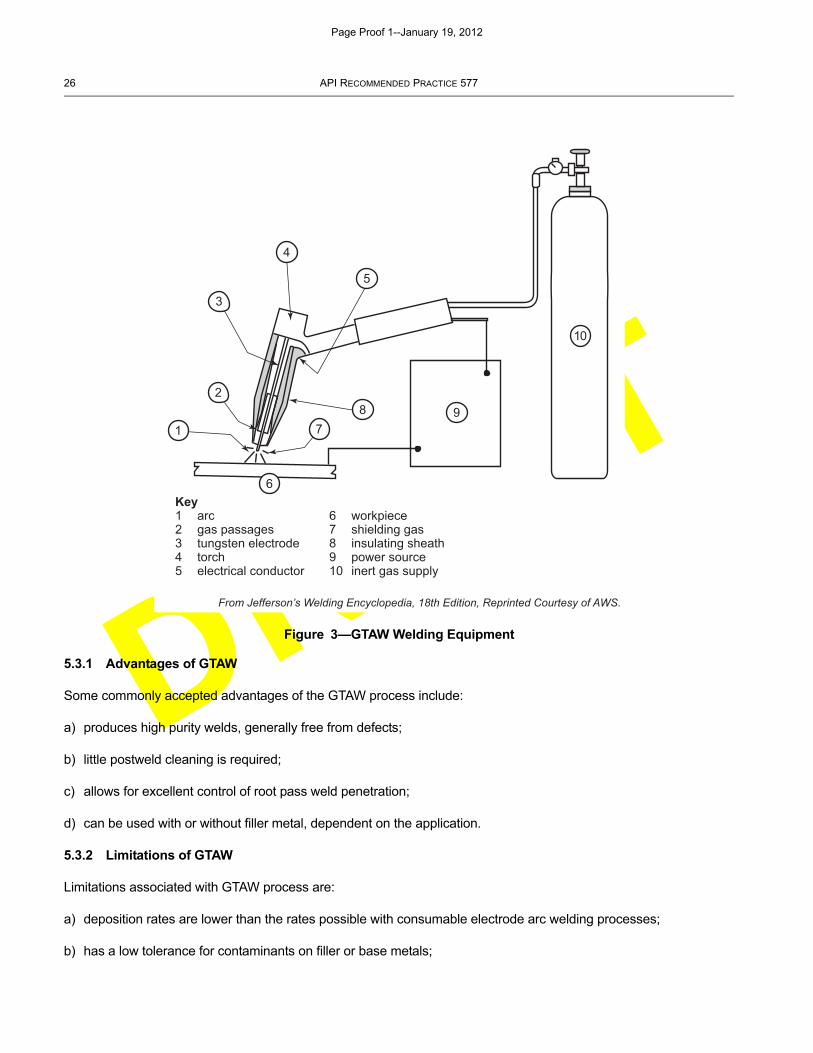
GTAW is an arc welding process that uses an arc between a non-consumable tungsten electrode and the weld pool.The process is commonly referred to as TIG (tungsten inert gas) or heliarc welding, and is used with a shielding gasand without the application of pressure. GTAW can be used with or without the addition of filler metal. The constantcurrent (CC) type power supply can be either dc or ac, and depends largely on the metal to be welded. Direct currentwelding is typically performed with the electrode negative (DCEN) polarity. DCEN welding offers the advantages ofdeeper penetration and faster welding speeds. Alternating current provides a cathodic cleaning (sputtering) thatremoves refractory oxides from the surfaces of the weld joint, which is necessary for welding aluminum andmagnesium. The cleaning action occurs during the portion of the ac wave, when the electrode is positive with respectto the work piece. See Figure 3 and Figure 4 for schematics of the GTAW equipment and welding process.
Page Proof 1--January 19, 2012
DRAFT
26 API RECOMMENDED PRACTICE 577
5.3.1 Advantages of GTAW
Some commonly accepted advantages of the GTAW process include:
a) produces high purity welds, generally free from defects;
b) little postweld cleaning is required;
c) allows for excellent control of root pass weld penetration;
d) can be used with or without filler metal, dependent on the application.
5.3.2 Limitations of GTAW
Limitations associated with GTAW process are:
a) deposition rates are lower than the rates possible with consumable electrode arc welding processes;
b) has a low tolerance for contaminants on filler or base metals;
Figure 3—GTAW Welding Equipment
From Jefferson’s Welding Encyclopedia, 18th Edition, Reprinted Courtesy of AWS.
Key1 arc2 gas passages3 tungsten electrode4 torch5 electrical conductor
6 workpiece7 shielding gas8 insulating sheath9 power source10 inert gas supply
3
4
5
2
19
6
78
10
Page Proof 1--January 19, 2012
DRAFT
WELDING PROCESSES, INSPECTION, AND METALLURGY 27
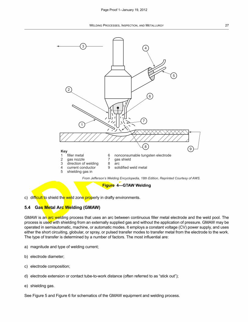
c) difficult to shield the weld zone properly in drafty environments.
5.4 Gas Metal Arc Welding (GMAW)
GMAW is an arc welding process that uses an arc between continuous filler metal electrode and the weld pool. Theprocess is used with shielding from an externally supplied gas and without the application of pressure. GMAW may beoperated in semiautomatic, machine, or automatic modes. It employs a constant voltage (CV) power supply, and useseither the short circuiting, globular, or spray, or pulsed transfer modes to transfer metal from the electrode to the work.The type of transfer is determined by a number of factors. The most influential are:
a) magnitude and type of welding current;
b) electrode diameter;
c) electrode composition;
d) electrode extension or contact tube-to-work distance (often referred to as “stick out”);
e) shielding gas.
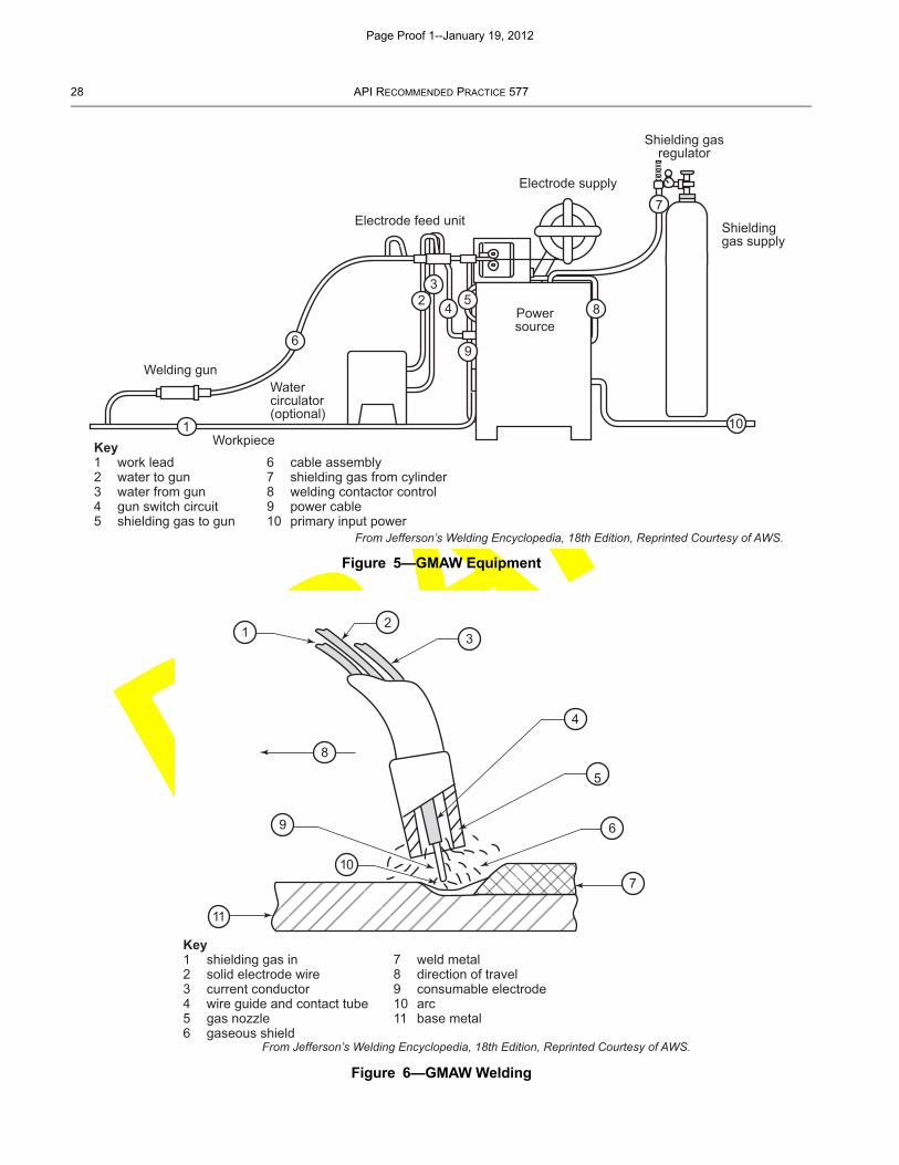
See Figure 5 and Figure 6 for schematics of the GMAW equipment and welding process.
Figure 4—GTAW Welding
From Jefferson’s Welding Encyclopedia, 18th Edition, Reprinted Courtesy of AWS.
Key1 filler metal2 gas nozzle3 direction of welding4 current conductor5 shielding gas in
6 nonconsumable tungsten electrode7 gas shield8 arc9 solidified weld metal
3
2
1
4
5
6
7
8 9
Page Proof 1--January 19, 2012
DRAFT
28 API RECOMMENDED PRACTICE 577
Figure 5—GMAW Equipment
Figure 6—GMAW Welding
Electrode supply
Electrode feed unit
Shielding gasregulator
Shieldinggas supply
Watercirculator(optional)
Welding gun
Workpiece
Powersource
10
7
8
9
54
32
6
1
From Jefferson’s Welding Encyclopedia, 18th Edition, Reprinted Courtesy of AWS.
Key1 work lead2 water to gun3 water from gun4 gun switch circuit5 shielding gas to gun
6 cable assembly7 shielding gas from cylinder8 welding contactor control9 power cable10 primary input power
From Jefferson’s Welding Encyclopedia, 18th Edition, Reprinted Courtesy of AWS.
Key1 shielding gas in2 solid electrode wire3 current conductor4 wire guide and contact tube5 gas nozzle6 gaseous shield
7 weld metal8 direction of travel9 consumable electrode10 arc11 base metal
12
3
4
5
6
7
8
9
10
11
Page Proof 1--January 19, 2012
DRAFT
WELDING PROCESSES, INSPECTION, AND METALLURGY 29
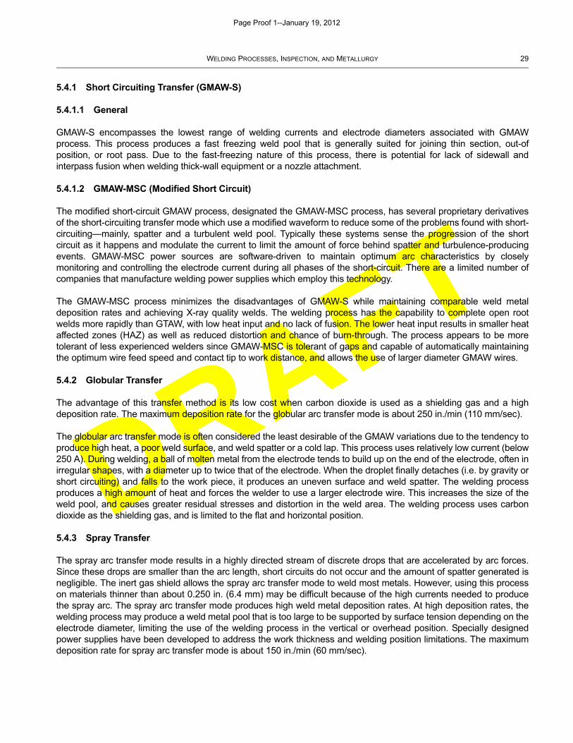
5.4.1 Short Circuiting Transfer (GMAW-S)
5.4.1.1 General
GMAW-S encompasses the lowest range of welding currents and electrode diameters associated with GMAWprocess. This process produces a fast freezing weld pool that is generally suited for joining thin section, out-ofposition, or root pass. Due to the fast-freezing nature of this process, there is potential for lack of sidewall andinterpass fusion when welding thick-wall equipment or a nozzle attachment.
5.4.1.2 GMAW-MSC (Modified Short Circuit)
The modified short-circuit GMAW process, designated the GMAW-MSC process, has several proprietary derivativesof the short-circuiting transfer mode which use a modified waveform to reduce some of the problems found with short-circuiting—mainly, spatter and a turbulent weld pool. Typically these systems sense the progression of the shortcircuit as it happens and modulate the current to limit the amount of force behind spatter and turbulence-producingevents. GMAW-MSC power sources are software-driven to maintain optimum arc characteristics by closelymonitoring and controlling the electrode current during all phases of the short-circuit. There are a limited number ofcompanies that manufacture welding power supplies which employ this technology.
The GMAW-MSC process minimizes the disadvantages of GMAW-S while maintaining comparable weld metaldeposition rates and achieving X-ray quality welds. The welding process has the capability to complete open rootwelds more rapidly than GTAW, with low heat input and no lack of fusion. The lower heat input results in smaller heataffected zones (HAZ) as well as reduced distortion and chance of burn-through. The process appears to be moretolerant of less experienced welders since GMAW-MSC is tolerant of gaps and capable of automatically maintainingthe optimum wire feed speed and contact tip to work distance, and allows the use of larger diameter GMAW wires.
5.4.2 Globular Transfer
The advantage of this transfer method is its low cost when carbon dioxide is used as a shielding gas and a highdeposition rate. The maximum deposition rate for the globular arc transfer mode is about 250 in./min (110 mm/sec).
The globular arc transfer mode is often considered the least desirable of the GMAW variations due to the tendency toproduce high heat, a poor weld surface, and weld spatter or a cold lap. This process uses relatively low current (below250 A). During welding, a ball of molten metal from the electrode tends to build up on the end of the electrode, often inirregular shapes, with a diameter up to twice that of the electrode. When the droplet finally detaches (i.e. by gravity orshort circuiting) and falls to the work piece, it produces an uneven surface and weld spatter. The welding processproduces a high amount of heat and forces the welder to use a larger electrode wire. This increases the size of theweld pool, and causes greater residual stresses and distortion in the weld area. The welding process uses carbondioxide as the shielding gas, and is limited to the flat and horizontal position.
5.4.3 Spray Transfer
The spray arc transfer mode results in a highly directed stream of discrete drops that are accelerated by arc forces.Since these drops are smaller than the arc length, short circuits do not occur and the amount of spatter generated isnegligible. The inert gas shield allows the spray arc transfer mode to weld most metals. However, using this processon materials thinner than about 0.250 in. (6.4 mm) may be difficult because of the high currents needed to producethe spray arc. The spray arc transfer mode produces high weld metal deposition rates. At high deposition rates, thewelding process may produce a weld metal pool that is too large to be supported by surface tension depending on theelectrode diameter, limiting the use of the welding process in the vertical or overhead position. Specially designedpower supplies have been developed to address the work thickness and welding position limitations. The maximumdeposition rate for spray arc transfer mode is about 150 in./min (60 mm/sec).
Page Proof 1--January 19, 2012
DRAFT
30 API RECOMMENDED PRACTICE 577
5.4.4 Pulsed Transfer
The pulsed arc GMAW method was developed to overcome the thickness and welding position limitations. PulsedGMAW welding is a variation of the GMAW process. The welding process uses:
1) a low background/constant current to sustain the arc without providing enough energy to produce drops at thetip of the wire; and
2) a superimposed/pulsing current with an amplitude greater than the transition current necessary for spraytransfer.
During the pulsing portion of the current cycle, one or more drops are formed and transferred. The frequency andamplitude of the pulses control the rate at which the wire melts. Pulsing makes the desirable features of spray arctransfer available for joining sheet metals and welding in all positions. The maximum deposition rate for pulsed arctransfer mode is about 200 in./min (85 mm/sec). The pulsed arc GMAC method requires a power source capable ofproviding current pulses with a frequency between 30 pulses/sec and 400 pulses/sec, and requires that the shieldinggas be primarily argon with a low carbon dioxide concentration.
5.4.5 Advantages of GMAW
Some commonly accepted advantages of the GMAW process include:
a) the only consumable electrode process that can be used to weld most commercial metals and alloys;
b) deposition rates are significantly higher than those obtained with SMAW;
c) minimal postweld cleaning is required due to the absence of a slag.
5.4.6 Limitations of GMAW
Limitations associated with GMAW are:
a) the welding equipment is more complex, more costly, and less portable than that for SMAW;
b) the welding arc should be protected from air drafts that will disperse the shielding gas;
c) when using the GMAW-S process, the weld is more susceptible to lack of adequate fusion.
5.5 Flux Cored Arc Welding (FCAW)
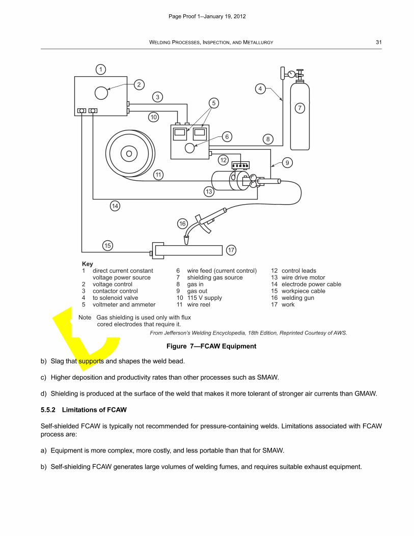
FCAW is an arc welding process that uses an arc between continuous tubular filler metal electrode and the weld pool.The process is used with shielding gas evolved from a flux contained within the tubular electrode, with or withoutadditional shielding from an externally supplied gas, and without the application of pressure. Normally asemiautomatic process, the use of FCAW depends on the type of electrodes available, the mechanical propertyrequirements of the welded joints, and the joint designs and fit-up. The recommended power source is the dcconstant-voltage type, similar to sources used for GMAW. Figure 7 shows a schematic of FCAW equipment, whileFigure 8 shows the welding process with additional gas shielding. Figure 9 shows a schematic of the self-shieldedFCAW process where no additional gas is used.
5.5.1 Advantages of FCAW
Some commonly accepted advantages of the FCAW process include:
a) The metallurgical benefits that can be derived from a flux.
Page Proof 1--January 19, 2012
DRAFT
WELDING PROCESSES, INSPECTION, AND METALLURGY 31
b) Slag that supports and shapes the weld bead.
c) Higher deposition and productivity rates than other processes such as SMAW.
d) Shielding is produced at the surface of the weld that makes it more tolerant of stronger air currents than GMAW.
5.5.2 Limitations of FCAW
Self-shielded FCAW is typically not recommended for pressure-containing welds. Limitations associated with FCAWprocess are:
a) Equipment is more complex, more costly, and less portable than that for SMAW.
b) Self-shielding FCAW generates large volumes of welding fumes, and requires suitable exhaust equipment.
Figure 7—FCAW Equipment
Note Gas shielding is used only with flux cored electrodes that require it.
From Jefferson’s Welding Encyclopedia, 18th Edition, Reprinted Courtesy of AWS.
Key1 direct current constant
voltage power source2 voltage control3 contactor control4 to solenoid valve5 voltmeter and ammeter
6 wire feed (current control)7 shielding gas source8 gas in9 gas out10 115 V supply11 wire reel
12 control leads13 wire drive motor14 electrode power cable15 workpiece cable16 welding gun17 work
1
2
3
10
5
4
6
7
8
912
13
11
14
16
1517
Page Proof 1--January 19, 2012
DRAFT
32 API RECOMMENDED PRACTICE 577
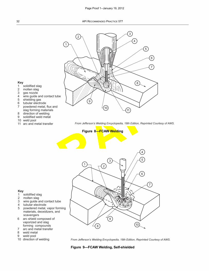
Figure 8—FCAW Welding
Figure 9—FCAW Welding, Self-shielded
From Jefferson’s Welding Encyclopedia, 18th Edition, Reprinted Courtesy of AWS.
Key1 solidified slag2 molten slag3 gas nozzle4 wire guide and contact tube5 shielding gas6 tubular electrode 7 powdered metal, flux and slag forming materials8 direction of welding9 solidified weld metal10 weld pool11 arc and metal transfer
1
23
4
5
6
7
8
9
1011
From Jefferson’s Welding Encyclopedia, 18th Edition, Reprinted Courtesy of AWS.
Key1 solidified slag2 molten slag3 wire guide and contact tube4 tubular electrode5 powdered metal, vapor forming materials, deoxidizers, and scavengers 6 arc shield composed of vaporized and slag forming compounds7 arc and metal transfer8 weld metal9 weld pool10 direction of welding
1 2
3
4
5
6
7
8
9
10
Page Proof 1--January 19, 2012
DRAFT
WELDING PROCESSES, INSPECTION, AND METALLURGY 33
c) Slag should be removed between weld passes, and removed from surfaces that will be inspected. If a weld isbeing placed in corrosive service, failure to remove slag from the weld cap or root can create sites for corrosion toinitiate.
d) Backing material is required for root pass welding.
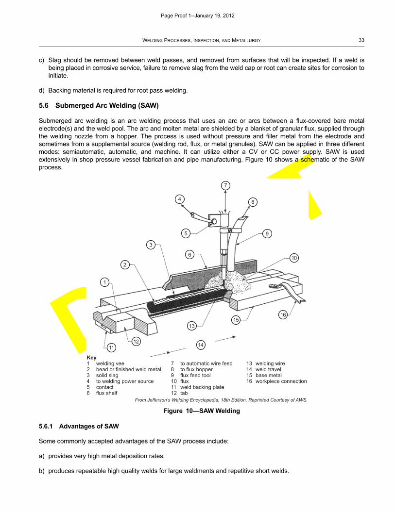
5.6 Submerged Arc Welding (SAW)
Submerged arc welding is an arc welding process that uses an arc or arcs between a flux-covered bare metalelectrode(s) and the weld pool. The arc and molten metal are shielded by a blanket of granular flux, supplied throughthe welding nozzle from a hopper. The process is used without pressure and filler metal from the electrode andsometimes from a supplemental source (welding rod, flux, or metal granules). SAW can be applied in three differentmodes: semiautomatic, automatic, and machine. It can utilize either a CV or CC power supply. SAW is usedextensively in shop pressure vessel fabrication and pipe manufacturing. Figure 10 shows a schematic of the SAWprocess.
5.6.1 Advantages of SAW
Some commonly accepted advantages of the SAW process include:
a) provides very high metal deposition rates;
b) produces repeatable high quality welds for large weldments and repetitive short welds.
Figure 10—SAW Welding
From Jefferson’s Welding Encyclopedia, 18th Edition, Reprinted Courtesy of AWS.
Key1 welding vee2 bead or finished weld metal3 solid slag4 to welding power source5 contact6 flux shelf
7 to automatic wire feed8 to flux hopper9 flux feed tool10 flux11 weld backing plate12 tab
13 welding wire14 weld travel15 base metal16 workpiece connection
1
2
3
5
6
4
7
8
9
10
1112
13
14
1516
Page Proof 1--January 19, 2012
DRAFT
34 API RECOMMENDED PRACTICE 577
5.6.2 Limitations of SAW
Limitations associated with SAW are:
a) a power supply capable of providing high amperage at 100 % duty cycle is recommended;
b) weld is not visible during the welding process;
c) equipment required is more costly and extensive, and less portable;
d) process is limited to shop applications and flat position.
5.7 Stud Arc Welding (SW)
5.7.1 General
SW is an arc welding process that uses an arc between a metal stud or similar part and the work piece. Once thesurfaces of the parts are properly heated, that is the end of the stud is molten and the work has an equal area ofmolten pool, they are brought into contact by pressure. Shielding gas or flux may or may not be used. The processmay be fully automatic or semiautomatic. A stud gun holds the tip of the stud against the work. Direct current istypically used for SW with the stud gun connected to the negative terminal (DCEN). The power source is a CC type.
SW is a specialized process predominantly limited to welding insulation and refractory support pins to tanks, pressurevessels and heater casing.
5.7.2 Advantages of SW
Some commonly accepted advantages of the SW process include:
a) high productivity rates compared to manually welding studs to base metal;
b) considered an all-position process.
5.7.3 Limitations of SW
Limitations of SW are:
a) process is primarily suitable for only carbon steel and low-alloy steels;
b) process is specialized to a few applications.
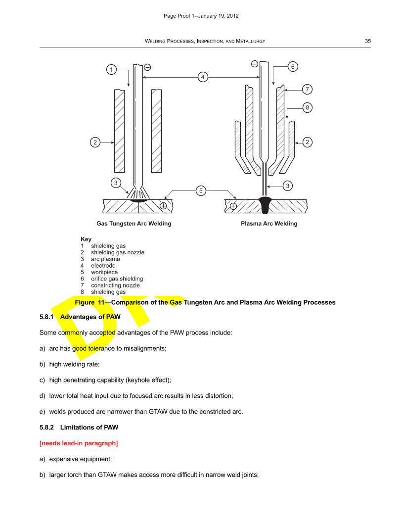
5.8 Plasma Arc Welding (PAW)
Plasma arc welding (PAW) is a variation of the gas tungsten arc welding (GTAW) process except that the tungstenelectrode is positioned within the body of the torch. There are two types of plasma arc welding, namely the transferredarc process and non-transferred arc process. In the plasma transferred arc (PTA), similar to GTAW, the workpiece ispart of the electrical circuit, and the arc is struck between the tungsten electrode and the workpiece as in the GTAWprocess. By constricting the arc, the plasma or ionized gas is forced through a fine-bore copper nozzle whichconstricts the arc, and exits the orifice at high velocities (approaching the speed of sound). The process produces acollimated arc which focuses the arc on a relatively small area of the workpiece with an arc temperature in excess of20,000 °F (11,093 °C). In the non transferred arc process (also referred as the plasma spray (PS) process, the arc isstruck between the tungsten electrode and the constricting nozzle rather than with the work-piece. The plasma sprayprocess is solely used for the deposition of surface coatings. It is not used for making strength welds. A comparison ofthe GTAW and PAW circuits and welding processes is shown in Figure 11.
Page Proof 1--January 19, 2012
DRAFT
WELDING PROCESSES, INSPECTION, AND METALLURGY 35
5.8.1 Advantages of PAW
Some commonly accepted advantages of the PAW process include:
a) arc has good tolerance to misalignments;
b) high welding rate;
c) high penetrating capability (keyhole effect);
d) lower total heat input due to focused arc results in less distortion;
e) welds produced are narrower than GTAW due to the constricted arc.
5.8.2 Limitations of PAW
[needs lead-in paragraph]
a) expensive equipment;
b) larger torch than GTAW makes access more difficult in narrow weld joints;
Figure 11—Comparison of the Gas Tungsten Arc and Plasma Arc Welding Processes
Gas Tungsten Arc Welding Plasma Arc Welding
Key1 shielding gas2 shielding gas nozzle3 arc plasma4 electrode5 workpiece6 orifice gas shielding7 constricting nozzle8 shielding gas
1
2 2
3 3
4
5
6
7
8
Page Proof 1--January 19, 2012
DRAFT
36 API RECOMMENDED PRACTICE 577
c) Focused arc requires better control by the welder
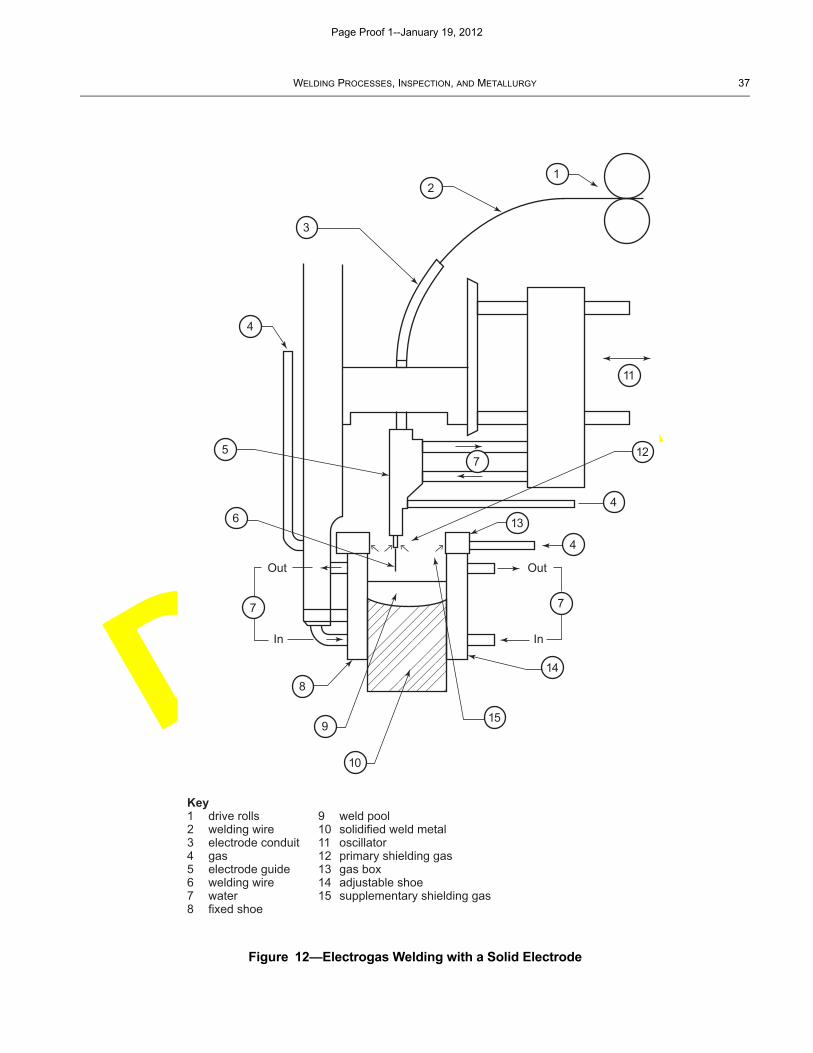
5.9 Electrogas Welding (EGW)
Electrogas welding (EGW) is similar to the GMAW process in that it can feed a solid electrode into the joint.Alternately, similar to the FCAW process, it can feed a flux cored tubular electrode. The weld is deposited in the flatposition with the molten metal continually being deposited at the bottom of the moving cavity. In electrogas welding,fixed or moving metal (usually copper) or ceramic shoes (or dams), water cooled if needed, are set up before starting,to bridge the gap between abutting plates and contain the molten metal until solidification is completed. The weldingprocess utilizes either a solid wire or flux-cored electrode. The weld area is protected from atmospheric contaminationby an externally supplied shielding gas, or by the gas produced by the disintegration of the flux-cored electrode wire.Electrogas welding is used to make square-groove welds for butt and T-joints in the construction of storage tanks,ship hulls and pressure vessels with plate thicknesses from 3/8 in. to 4 in. (10 mm to 100 mm). The workpiece must beat least 0.4 in. (10 mm) thick, while the maximum thickness for one electrode is approximately 0.8 in. (20 mm).Additional electrodes make it possible to weld thicker workpieces. The height of the weld is limited only by themechanism used to lift the welding head. In general, it ranges from 4 in. (100 mm) to 50 ft (20 m).
Low and medium carbon steels, low alloy high strength steels, and some stainless steels can be welded using theelectrogas process. Quenched and tempered steels may also be welded by the process, provided that the properamount of heat is applied. Figure 12 shows an electrogas welding set-up using a solid electrode.
5.9.1 Advantages of EGW
Some commonly accepted advantages of the EGW process include:
a) welding is usually done in one pass;
b) very high deposition rates;
c) minimum distortion.
5.9.2 Limitations of EGW
Some limitations of EGW include:
a) poor toughness;
b) massive, expensive welding equipment and guidance systems are required;
c) lengthy set-up times are needed;
d) can only be used with vertically positioned joints;
e) can require external source of shielding gas.
6 Welding Procedure
6.1 General
Qualified welding procedures are required for welding fabrication and repair of pressure vessels, piping and tanks.They detail the steps necessary to make a specific weld and generally consist of a written description, details of the
Page Proof 1--January 19, 2012
DRAFT
WELDING PROCESSES, INSPECTION, AND METALLURGY 37
Figure 12—Electrogas Welding with a Solid Electrode
Key1 drive rolls2 welding wire3 electrode conduit4 gas5 electrode guide6 welding wire7 water8 fixed shoe
9 weld pool10 solidified weld metal11 oscillator12 primary shielding gas13 gas box14 adjustable shoe15 supplementary shielding gas
Out
In
Out
In
12
3
4
5
6
7
8
9
10
11
712
4
13
4
7
14
15
Page Proof 1--January 19, 2012
DRAFT
38 API RECOMMENDED PRACTICE 577
weld joint and welding process variables, and test data to demonstrate the procedure produces weldments that meetdesign requirements.
While various codes and standards exist for the development of welding procedures, this section reflects criteriadescribed in ASME Section IX. Welding procedures qualified to ASME Section IX are required by API inspectioncodes for repair welding and are often required by construction codes used in fabrication of new equipment andpiping. However, construction codes and proprietary company specifications may have additional requirements orallow specific exceptions so they should be reviewed for each weld application.
Welding procedures required by ASME Section IX will include a written welding procedure specification (WPS) andprocedure qualification record (PQR). The WPS provides direction to the welder while making production welds toASME code requirements. The PQR is a record of the welding data and variables used to weld a test coupon and thetest results used to qualify the welding procedure.
It is important to differentiate the PQR and welder performance qualification (WPQ), detailed in Section 7. Thepurpose of the PQR is to establish the properties of the weldment. The purpose of the WPQ is to establish the welderis capable of making a quality weld using the welding procedure.
6.2 Welding Procedure Specification (WPS)
ASME Section IX requires each manufacturer and contractor to develop welding procedures. Whereas thisrequirement appears repetitious, qualified welding procedure specifications are an important aspect of fabricationquality control. They help each organization recognize the significance of changes in welding variables that may berequired on the job, and the effects of the changes on weldment properties. The WPS is but one step for weldingfabrication quality assurance. ASME B31.3 allows welding procedure qualification by others, provided it is acceptableto the inspector and meets certain conditions.
The completed WPS for a welding process addresses all essential, nonessential, and supplementary essentialvariables when impact testing is required, or when specified by the end user. Essential variables affect themechanical properties of the weld. If they are changed beyond what the reference code paragraph allows for theprocess, the WPS must be re-qualified. Nonessential variables do not affect the mechanical properties of the weld.They may be changed on the WPS without re-qualifying the welding procedure. Supplementary essential variablesapply or when specified by the end user. They are treated as essential variables when they apply.
6.2.1 Types of Essential Variables
The WPS should contain, as a code requirement, the following information:
a) process(es);
b) base metal;
c) filler metal (and/or flux);
d) welding current;
e) welding position;
f) shielding gas, if used;
g) preparation of base metal;
h) fit-up and alignment;
Page Proof 1--January 19, 2012

DRAFT
WELDING PROCESSES, INSPECTION, AND METALLURGY 39
i) backside of joint;
j) peening;
k) preheat;
l) postweld heat treatment;
m) welding technique (weaving, multiple or single pass, etc.);
n) cleaning method;
o) back gouge method.
6.2.2 Other Requirements
The WPS should also reference the supporting PQR(s) used to qualify the welding procedure. In addition, theconstruction code or proprietary company specifications can impose specific requirements related to service of theequipment and piping. These can include:
a) toughness of base metal, weld metal, and HAZ;
b) limitations of welding process;
c) limitations of filler metals and fluxes;
d) critical joint geometries;
e) limitations on preheat;
f) limitations on PWHT;
g) limitations on weld metal hardness;
h) limitations on the chemical composition of base metal and filler metal;
i) base metal heat treatment condition limitation;
j) limitations on thickness.
These requirements should be reflected in the WPS.
The format of the WPS is not fixed, provided it addresses all essential and nonessential variables (and supplementaryessential variables when necessary). An example form is available in ASME Section IX, Annex B.
The WPS should be available for review by the Inspector. Since it provides the limits the welder is responsible forstaying within, it should be available to the welder as well.
6.3 Procedure Qualification Record (PQR)
The PQR records the essential and nonessential variables used to weld a test coupon, the coupon test results, andthe manufacturer’s certification of accuracy in the qualification of a WPS. Record of the nonessential variables usedduring the welding of the test coupon is optional.
Page Proof 1--January 19, 2012
DRAFT
40 API RECOMMENDED PRACTICE 577
ASME Section IX requires that the manufacturer or contractor supervise the production of the test weldments andcertify that the PQR properly qualifies the welding procedure; however, other groups may perform sample preparationand testing. Mechanical tests are required to qualify a welding procedure to demonstrate the properties of theweldment. Test sample selection and testing requirements are defined in Section IX. Typically, they will includetension test to determine the ultimate strength of a groove weld, guided bend tests to determine the degree ofsoundness and ductility of a groove weld, notch toughness testing when toughness requirements are imposed, andhardness measurements when hardness restrictions are defined. If any test specimen fails, the test coupon fails anda new coupon will be required.
The format of the PQR is not fixed, provided it addresses all essential variables (and supplementary essentialvariables when necessary). An example form is available in ASME Section IX, Annex B.
The PQR should accompany the WPS and be available for review by the Inspector upon request. It does not need tobe available to the welder. One PQR may support several WPSs. One WPS may be qualified by more than one PQRwithin the limitations of the code.
6.4 Reviewing a WPS and PQR
6.4.1 General
Inspectors should review the WPS and PQR to verify they are acceptable for the welding to be done. While there aremany ways to review a welding procedure, the most effective one utilizes a systematic approach that assures acomplete and thorough review of the WPS and PQR to verify that all ASME Section IX and construction and repaircode requirements have been satisfied.
The initial step is to verify the WPS has been properly completed and addresses the requirements of Section IX andthe construction/repair code. The second step is to verify the PQR has been properly completed and addresses allthe requirements of Section IX and the construction and repair code. The third step is to confirm the PQR essentialvariable values properly support the range specified in the WPS.
For simplicity purposes, the following list is for a single weld process on the WPS when notch toughness is not arequirement (so supplementary essential variables do not apply).
6.4.2 Items to be Included in the WPS
[needs lead-in paragraph]
a) Name of the company using the procedure.
b) Name of the individual that prepared the procedure.
c) Unique number or designation that will distinguish it from any others, and date.
d) Supporting PQR(s).
e) Current revision and date, if revised.
f) Applicable welding process (i.e. SMAW, GTAW, GMAW, FCAW, SAW).
g) Type of welding process (i.e. automatic, manual, machine, or semi-automatic).
h) Backing material, if any, used for each process. The joint design information applicable to the process (i.e. type ofjoint, groove angle, root spacing, root face dimensions, backing material and function).
Page Proof 1--January 19, 2012
DRAFT
WELDING PROCESSES, INSPECTION, AND METALLURGY 41
i) Base metal’s P-number and, if applicable, group number of the metals being joined, or specification type andgrade, or chemical analysis and mechanical properties.
j) Thickness range the procedure is to cover.
k) Diameter (for piping) the procedure is to cover.
l) Filler metal specification (SFA number).
m) AWS classification number.
n) F-number (see QW-432).
o) A-number (see QW-442).
p) Filler metal size.
q) Deposited metal thickness and passes greater than 1/2 in. (12.7 mm) thickness.
r) Electrode-flux class and trade name, if used.
s) Consumable insert, if used.
t) Position and progression qualified for use in production welding.
u) Minimum preheat temperature (including preheat maintenance requirements) and maximum interpasstemperature the weldment is to receive throughout welding.
v) Postweld heat treatment temperature and hold time (if applied).
w) Type, composition, and flow rates for shielding, trailing, and backing gases (if used).
x) Current, polarity, amperage range, and voltage range for production welding (for each electrode size, position, andthickness, etc.).
y) Tungsten electrode size and type (if GTAW).
z) Metal transfer mode (if GMAW or FCAW).
aa)Technique including string or weave bead, initial and interpass cleaning, peening, and other weld process specificnonessential variables.
6.4.3 Items to be Included in the PQR
[needs lead-in paragraph]
a) Name of the company that qualified the procedure.
b) Unique number or designation and the date.
c) WPS number that the PQR supports.
d) Type of weld for qualification (groove, fillet, other).
Page Proof 1--January 19, 2012
DRAFT
42 API RECOMMENDED PRACTICE 577
e) Test coupon thickness.
f) Test coupon diameter.
g) P-numbers of coupon welded.
h) Filler metal F-number.
i) Filler metal A-number.
j) Position and progression.
k) Total weld metal thickness deposited.
l) Any single weld pass thickness greater than 1/2 in. (12.7 mm).
m) Preheat temperature.
n) PWHT temperature and thickness limit.
o) Gas.
p) Electrical Characteristics.
q) Technique.
r) Proper number, size, and test results for tensile tests.
s) Proper number, type, and results for bend tests.
t) Additional test results if required by construction code or project specification.
u) Certification signature and date.
v) Welder’s Name.
w) Tests Conducted by & Record number.
x) Maximum interpass temperature recorded.
The review should confirm that the PQR variables adequately represent and support the range specified in the WPSfor the production application. While this example serves to illustrate a suggested approach to reviewing weldingprocedures, it has not addressed specific variables and nuances required to have a properly qualified weldingprocedure. Additionally, Annex C provides an example of using a checklist for the review of WPS and PQRs.
6.5 Tube-to-Tubesheet Welding Procedures
6.5.1 General
Tube-to-tubesheet welds have many factors affecting weld quality that are different than that for conventional grooveand fillet welds. These factors result mainly from the unique geometry of the welds. Therefore, a demonstrationmockup in accordance with ASME IX QW-193 may be required by the construction code or proprietary companyspecifications.
Page Proof 1--January 19, 2012
DRAFT
WELDING PROCESSES, INSPECTION, AND METALLURGY 43
6.5.2 Essential Variables
The types of essential variables listed in ASME IX QW-288 include:
a) joint configuration;
b) tube and tubesheet thickness
c) ligament thickness
d) multi versus single pass
e) welding position
f) interpass temperature
g) tube expansion
h) cleaning method
i) electrode or filler metal diameter
j) inserts
k) specific requirements for explosive welding
l) weld process and type;
m) vertical position progression;
n) P# and A#;
o) preheat;
p) PWHT;
q) weld current level;
r) polarity or current type;
s) welding type;
t) F Number;
u) shielding gas;
v) gas flow rate.
6.5.3 Procedure Qualification Test
The procedure qualification test requirements for tube-to-tubesheet welds are specified in ASME IX QW-193. Thetests include:
a) visual;
b) dye penetrant;
c) macro examination of weld cross sections.
Other testing that may be specified by the construction code or proprietary company specifications include:
a) hardness testing;
b) shear load test in accordance with ASME VIII, Div. 1, Annex A.
Page Proof 1--January 19, 2012
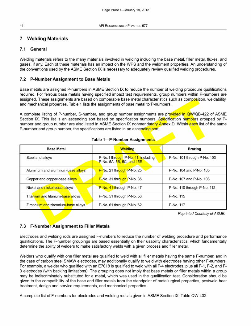
DRAFT
44 API RECOMMENDED PRACTICE 577
7 Welding Materials
7.1 General
Welding materials refers to the many materials involved in welding including the base metal, filler metal, fluxes, andgases, if any. Each of these materials has an impact on the WPS and the weldment properties. An understanding ofthe conventions used by the ASME Section IX is necessary to adequately review qualified welding procedures.
7.2 P-Number Assignment to Base Metals
Base metals are assigned P-numbers in ASME Section IX to reduce the number of welding procedure qualificationsrequired. For ferrous base metals having specified impact test requirements, group numbers within P-numbers areassigned. These assignments are based on comparable base metal characteristics such as composition, weldability,and mechanical properties. Table 1 lists the assignments of base metal to P-numbers.
A complete listing of P-number, S-number, and group number assignments are provided in QW/QB-422 of ASMESection IX. This list is an ascending sort based on specification numbers. Specification numbers grouped by P-number and group number are also listed in ASME Section IX nonmandatory Annex D. Within each list of the sameP-number and group number, the specifications are listed in an ascending sort.
7.3 F-Number Assignment to Filler Metals
Electrodes and welding rods are assigned F-numbers to reduce the number of welding procedure and performancequalifications. The F-number groupings are based essentially on their usability characteristics, which fundamentallydetermine the ability of welders to make satisfactory welds with a given process and filler metal.
Welders who qualify with one filler metal are qualified to weld with all filler metals having the same F-number, and inthe case of carbon steel SMAW electrodes, may additionally qualify to weld with electrodes having other F-numbers.For example, a welder who qualified with an E7018 is qualified to weld with all F-4 electrodes, plus all F-1, F-2, and F-3 electrodes (with backing limitations). The grouping does not imply that base metals or filler metals within a groupmay be indiscriminately substituted for a metal, which was used in the qualification test. Consideration should begiven to the compatibility of the base and filler metals from the standpoint of metallurgical properties, postweld heattreatment, design and service requirements, and mechanical properties.
A complete list of F-numbers for electrodes and welding rods is given in ASME Section IX, Table QW-432.
Table 1—P-Number Assignments
Base Metal Welding Brazing
Steel and alloys P-No.1 through P-No. 11, including P-No. 5A, 5B, 5C, and 15E
P-No. 101 through P-No. 103
Aluminum and aluminum-base alloys P-No. 21 through P-No. 25 P-No. 104 and P-No. 105
Copper and copper-base alloys P-No. 31 through P-No. 35 P-No. 107 and P-No. 108
Nickel and nickel-base alloys P-No. 41 through P-No. 47 P-No. 110 through P-No. 112
Titanium and titanium-base alloys P-No. 51 through P-No. 53 P-No. 115
Zirconium and zirconium-base alloys P-No. 61 through P-No. 62 P-No. 117
Reprinted Courtesy of ASME.
Page Proof 1--January 19, 2012
DRAFT
WELDING PROCESSES, INSPECTION, AND METALLURGY 45
7.4 AWS Classification of Filler Metals
An AWS classification number identifies electrodes and welding rods. The AWS classification numbers are specifiedin ASME Section IIC under their appropriate SFA specification number. ASME Section IX Table QW-432 lists theAWS classification numbers and SFA specification numbers included under each of the F-numbers. Note that the X’sin the AWS classification numbers represent numerals, i.e. the AWS classifications E6010, E7010, E8010, E9010,and E10010 are all covered by F-number 3 (EXX10). Annex A contains additional details on the conventions used inidentification of filler metals for the welding processes.
7.5 A-Number
To minimize the number of welding procedure qualifications, steel and steel alloy filler metals are also groupedaccording to their A-number. The A-number grouping in ASME Section IX, Table QW-442 is based on the chemicalcomposition of the deposited weld metal. This grouping does not imply that filler metals may be indiscriminatelysubstituted without consideration for the compatibility with the base metal and the service requirements.
7.6 Filler Metal Selection
Inspectors should verify the filler metal selection is appropriate for the base metal being welded. Some considerationsin selection include:
a) chemical composition of filler metal;
b) tensile strength of filler metal and base metal;
c) dilution of alloying elements from base metal;
d) hardenability of filler metal;
e) susceptibility to hot cracking;
f) corrosion resistance of filler metal.
Annex D provides a guide of common filler metals for base metals most often used in petrochemical plants. Inaddition, there is a table comparing the current AWS filler metal classification to the previous ones for low-alloy steels.AWS modified the classifications for several common low-alloy filler metals.
7.7 Consumable Storage and Handling
Welding consumable storage and handled guidelines should be in accordance with the consumable manufacturer’sinstructions and guidelines and as given in the AWS A5.XX series of filler metal specifications. Covered electrodesexposed to moisture can become unstable due to moisture pickup by the coating. Particularly susceptible to moisturepickup are coatings on low-hydrogen electrodes and stainless steel electrodes. Moisture can be a source ofhydrogen.
To reduce exposure to moisture, certain welding consumables should be stored in warm holding ovens after theyhave been removed from the manufacturer’s packaging. Low-hydrogen SMAW electrodes supplied in non-hermetically sealed containers should be baked according to manufacturer’s instructions prior to use. They should bestored separately from other types of electrodes with higher hydrogen content, as this can be another source forhydrogen pickup. Some welding consumables that are slightly damp can be reconditioned by baking in separatespecial ovens. Ovens should be heated by electrical means and have automatic heat controls and visible temperatureindications. Ovens should only be used for electrode storage as using them for food storage or cooking could causeelectrode coatings to absorb moisture. Any electrodes or fluxes that have become wet should be discarded.
Page Proof 1--January 19, 2012
DRAFT
46 API RECOMMENDED PRACTICE 577
8 Welder Qualification
8.1 General
Welder performance qualification is to establish the welder’s ability to deposit sound weld metal. Similar to weldingprocedure qualification, this section reflects the parameters in the referencing code or typically referenced to ASMESection IX. Other codes exist which utilize other means for welder qualification. The term welder is intended to applyto both welders and welding operators for the purpose of the following descriptions.
The welder qualification is limited by the essential variables given for each process. A welder may be qualified byradiography of a test coupon or of an initial production weld or by bend tests of a test coupon. Some end users andcodes limit or restrict the use of radiography. The responsibility for qualifying welders is typically restricted to thecontractor or manufacturer employing the welder and cannot be delegated to another organization. However, somecodes such as B31.3 may modify this rule and generally it is permissible to subcontract test specimen preparationand NDE.
8.2 Welder Performance Qualification (WPQ)
The WPQ addresses all essential variables listed in QW-350 of ASME Section IX. The performance qualification testcoupon is to be welded according to the qualified WPS, and the welding is supervised and controlled by the employerof the welder. The qualification is for the welding process used, and each different welding process requiresqualification. A change in any essential variable listed for the welding process requires the welder to re-qualify for thatprocess.
QW-352 through QW-357 in ASME Section IX, list the essential variables and referencing code paragraphs fordifferent welding processes. The variable groups addressed are: joints, base metals, filler metals, positions, gas, andelectrical characteristics.
The record of the WPQ test includes all the essential variables, the type of test and test results, and the rangesqualified. The format of the WPQ is not fixed provided it addresses all the required items. An example form isavailable in ASME Section IX—Form QW-484 in nonmandatory Annex B.
Mechanical tests performed on welder and welding operator qualification test coupons are defined in ASME SectionIX, QW-452 for type and number required. If radiographic examination is used for welder or welding operatorqualification of coupons, the minimum length of coupon to be examined is 6 in. (152.4 mm), and includes the entireweld circumference for pipe coupons. Coupons are required to pass visual examination and physical testing, if used.Alternately, welders and welding operators making a groove weld using SMAW, SAW, GTAW, and GMAW (exceptshort-circuit mode) may be qualified using radiography of the first production weld. For welders, a minimum of 6 in.(150 mm) length of the first production weld must be examined for performance qualification while a minimum of 3 ft(0.91 m) length must be examined for welding operators.
There are rules (e.g. ASME Section IX) for the immediate retesting of welders or welding operators who fail aqualification test and is commonly referred to as the “two for one rule” whereby the welder/operator must be tested ontwice the original extent of tests. Welders or welding operators who fail the second test typically have to be sent forretraining but no clear guidance is provided to inspectors on what constitutes retraining. Documented evidence ofretraining and production of acceptable practice welds should be presented to the inspector before allowing a furthertest.
Welder performance qualification expires if the welding process is not used during a six-month period. The welder’squalification can be revoked if there is a reason to question their ability to make welds. A welder’s log or continuityreport can be used to verify that a welder’s qualifications are current.
Page Proof 1--January 19, 2012
DRAFT
WELDING PROCESSES, INSPECTION, AND METALLURGY 47
8.3 Reviewing a WPQ
8.3.1 Review Prior to Welding
Prior to any welding, inspectors should review welders’ WPQ to verify they are qualified to perform the welding givenits position and process. When reviewing a WPQ, items to check include:
a) welders name and stamp number;
b) welding process and type;
c) identification of WPS used for welding test coupon;
d) backing (if used);
e) P-number(s) of base metals joined;
f) thickness of base metals and diameter if pipe;
g) filler metal SFA number;
h) filler metal F-number;
i) consumable insert (if used);
j) deposited thickness (for each process used);
k) welding position of the coupon;
l) vertical weld progression;
m) backing gas used;
n) metal transfer mode (if GMAW);
o) weld current type/polarity (if GTAW);
p) if machine welded—refer to QW-484 for additional values required;
q) guided bend test type and results, if used;
r) visual examination results;
s) additional requirements of the construction code;
t) testing organization identification, signature, and date;
u) radiographic results (if used).
8.3.2 Verifying the Qualification Range
The following ASME Section IX references should be used to verify the qualification range:
a) base metal qualification—QW- 423.1 and QW-403.15;
Page Proof 1--January 19, 2012
DRAFT
48 API RECOMMENDED PRACTICE 577
b) backing—QW-350 and QW-402.4;
c) deposited weld metal thickness qualification—QW-452.1 (if transverse bend tests) and QW-404.30;
d) groove weld small diameter limits—QW-452.3 and QW-403.16;
e) position and diameter limits—QW-461.9, QW-405.3 and QW-403.16;
f) F-number—QW-433 and QW-404.15.
8.3.3 Welder Qualifications for Tube to Tubesheet Welding
When a demonstration mockup in accordance with ASME IX QW-193 is required by the construction code orproprietary company specifications the welder qualification requirements have the same essential variables andacceptable ranges as in the welding procedure qualification (WPQ) used to support the welding procedurespecification (WPS).
8.3.4 Limitations for Welder Qualifications
Limitations for welders or welding operators are discussed in ASME Section IX, Para. QW-305.
9 Non-destructive Examination
9.1 Discontinuities
Non-destructive Examination (NDE) is defined as those inspection methods, which allow materials to be examinedwithout changing or destroying their usefulness. NDE is an integral part of the quality assurance program. A numberof NDE methods are employed to ensure that the weld meets design specifications and does not contain defects.
The inspector should choose an NDE method that has the capability and adequate sensitivity to detect discontinuitiesin the weld joints requiring examination for accept/reject evaluation. Table 2 and Figure 13 list the common types andlocation of discontinuities and illustrate their positions within a butt weld. The most commonly used NDE methodsused during weld inspection are shown in Table 3.
Table 4 lists the various weld joint types and common NDE methods available to inspect their configuration. Table 5further lists the detection capabilities of the most common NDE methods. Additional methods, like alternating currentfield measurement (ACFM), have applications in weld inspection and are described in this section but are lesscommonly used.
The inspector should be aware of discontinuities common to specific base metals and weld processes to assurethese discontinuities are detectable. Table 6 is a summary of these discontinuities, potential NDE methods andpossible solutions to the weld process.
9.2 Materials Identification
During welding inspection, the inspector should verify the conformance of the base material and filler metalchemistries with the selected or specified alloyed materials. This should include reviewing the certified mill test report,reviewing stamps or markings on the components, or require PMI testing. It is the responsibility of the owner/user toestablish a written material verification program indicating the extent and type of PMI to be as outlined in API 578.
Page Proof 1--January 19, 2012
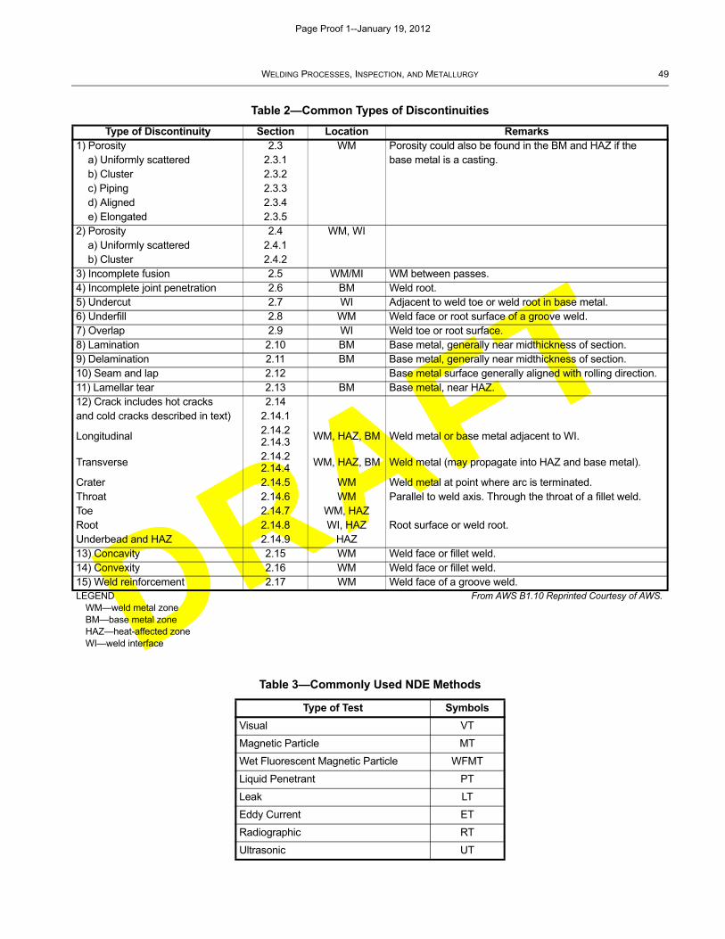
DRAFT
WELDING PROCESSES, INSPECTION, AND METALLURGY 49
Table 2—Common Types of Discontinuities
Type of Discontinuity Section Location Remarks1) Porosity 2.3 WM Porosity could also be found in the BM and HAZ if the
a) Uniformly scattered 2.3.1 base metal is a casting.b) Cluster 2.3.2c) Piping 2.3.3d) Aligned 2.3.4e) Elongated 2.3.5
2) Porosity 2.4 WM, WIa) Uniformly scattered 2.4.1b) Cluster 2.4.2
3) Incomplete fusion 2.5 WM/MI WM between passes.4) Incomplete joint penetration 2.6 BM Weld root.5) Undercut 2.7 WI Adjacent to weld toe or weld root in base metal.6) Underfill 2.8 WM Weld face or root surface of a groove weld.7) Overlap 2.9 WI Weld toe or root surface.8) Lamination 2.10 BM Base metal, generally near midthickness of section.9) Delamination 2.11 BM Base metal, generally near midthickness of section.10) Seam and lap 2.12 Base metal surface generally aligned with rolling direction.11) Lamellar tear 2.13 BM Base metal, near HAZ.12) Crack includes hot cracks 2.14and cold cracks described in text) 2.14.1
Longitudinal 2.14.22.14.3
WM, HAZ, BM Weld metal or base metal adjacent to WI.
Transverse 2.14.22.14.4 WM, HAZ, BM Weld metal (may propagate into HAZ and base metal).
Crater 2.14.5 WM Weld metal at point where arc is terminated.Throat 2.14.6 WM Parallel to weld axis. Through the throat of a fillet weld.Toe 2.14.7 WM, HAZRoot 2.14.8 WI, HAZ Root surface or weld root.Underbead and HAZ 2.14.9 HAZ13) Concavity 2.15 WM Weld face or fillet weld.14) Convexity 2.16 WM Weld face or fillet weld.15) Weld reinforcement 2.17 WM Weld face of a groove weld.LEGEND From AWS B1.10 Reprinted Courtesy of AWS.
WM—weld metal zoneBM—base metal zoneHAZ—heat-affected zoneWI—weld interface
Table 3—Commonly Used NDE Methods
Type of Test Symbols
Visual VT
Magnetic Particle MT
Wet Fluorescent Magnetic Particle WFMT
Liquid Penetrant PT
Leak LT
Eddy Current ET
Radiographic RT
Ultrasonic UT
Page Proof 1--January 19, 2012
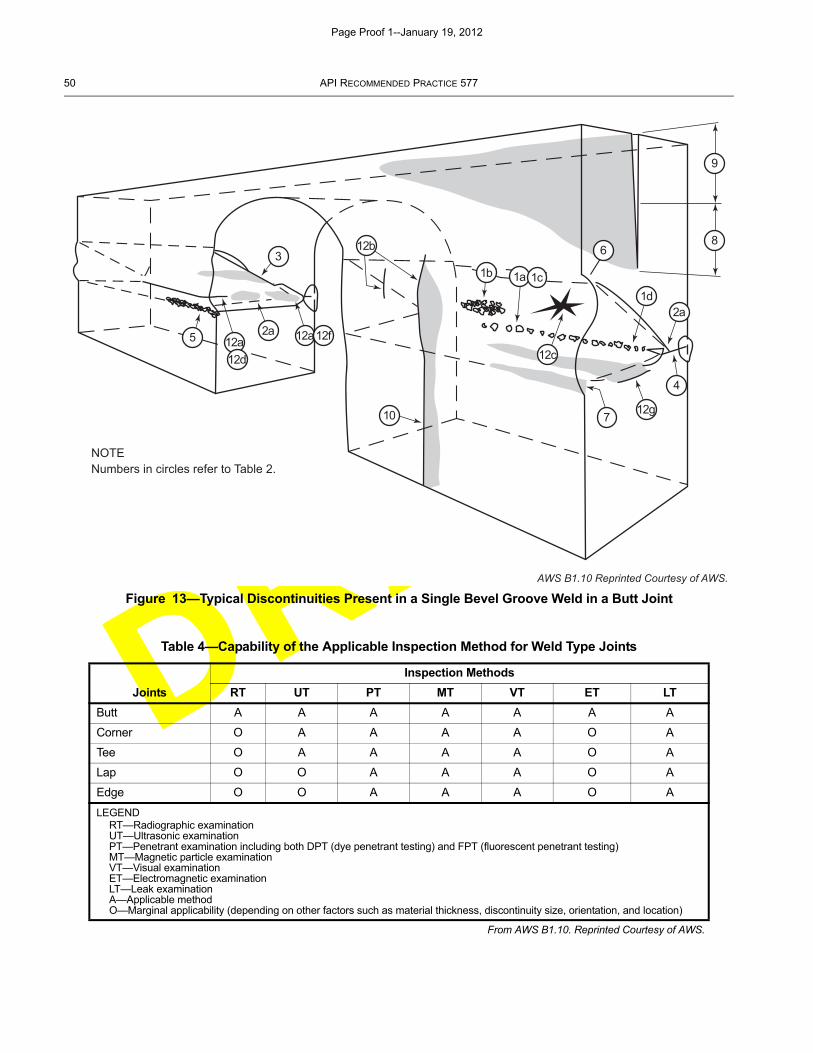
DRAFT
50 API RECOMMENDED PRACTICE 577
Figure 13—Typical Discontinuities Present in a Single Bevel Groove Weld in a Butt Joint
Table 4—Capability of the Applicable Inspection Method for Weld Type Joints
Inspection Methods
Joints RT UT PT MT VT ET LT
Butt A A A A A A A
Corner O A A A A O A
Tee O A A A A O A
Lap O O A A A O A
Edge O O A A A O A
LEGENDRT—Radiographic examinationUT—Ultrasonic examinationPT—Penetrant examination including both DPT (dye penetrant testing) and FPT (fluorescent penetrant testing)MT—Magnetic particle examinationVT—Visual examinationET—Electromagnetic examinationLT—Leak examinationA—Applicable methodO—Marginal applicability (depending on other factors such as material thickness, discontinuity size, orientation, and location)
From AWS B1.10. Reprinted Courtesy of AWS.
NOTENumbers in circles refer to Table 2.
1b
1d1a 1c
2a2a
3
12g
12c
12b
12a12a 12f
12d
4
710
5
68
9
AWS B1.10 Reprinted Courtesy of AWS.
Page Proof 1--January 19, 2012
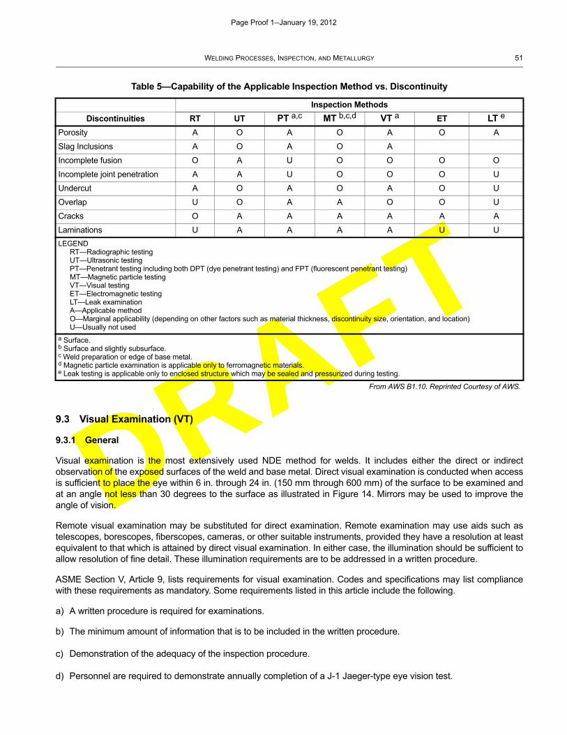
DRAFT
WELDING PROCESSES, INSPECTION, AND METALLURGY 51
9.3 Visual Examination (VT)
9.3.1 General
Visual examination is the most extensively used NDE method for welds. It includes either the direct or indirectobservation of the exposed surfaces of the weld and base metal. Direct visual examination is conducted when accessis sufficient to place the eye within 6 in. through 24 in. (150 mm through 600 mm) of the surface to be examined andat an angle not less than 30 degrees to the surface as illustrated in Figure 14. Mirrors may be used to improve theangle of vision.
Remote visual examination may be substituted for direct examination. Remote examination may use aids such astelescopes, borescopes, fiberscopes, cameras, or other suitable instruments, provided they have a resolution at leastequivalent to that which is attained by direct visual examination. In either case, the illumination should be sufficient toallow resolution of fine detail. These illumination requirements are to be addressed in a written procedure.
ASME Section V, Article 9, lists requirements for visual examination. Codes and specifications may list compliancewith these requirements as mandatory. Some requirements listed in this article include the following.
a) A written procedure is required for examinations.
b) The minimum amount of information that is to be included in the written procedure.
c) Demonstration of the adequacy of the inspection procedure.
d) Personnel are required to demonstrate annually completion of a J-1 Jaeger-type eye vision test.
Table 5—Capability of the Applicable Inspection Method vs. Discontinuity
Inspection Methods
Discontinuities RT UT PT a,c MT b,c,d VT a ET LT e
Porosity A O A O A O A
Slag Inclusions A O A O A
Incomplete fusion O A U O O O O
Incomplete joint penetration A A U O O O U
Undercut A O A O A O U
Overlap U O A A O O U
Cracks O A A A A A A
Laminations U A A A A U U
LEGENDRT—Radiographic testingUT—Ultrasonic testingPT—Penetrant testing including both DPT (dye penetrant testing) and FPT (fluorescent penetrant testing)MT—Magnetic particle testingVT—Visual testingET—Electromagnetic testingLT—Leak examinationA—Applicable methodO—Marginal applicability (depending on other factors such as material thickness, discontinuity size, orientation, and location)U—Usually not used
a Surface.b Surface and slightly subsurface.c Weld preparation or edge of base metal.d Magnetic particle examination is applicable only to ferromagnetic materials.e Leak testing is applicable only to enclosed structure which may be sealed and pressurized during testing.
From AWS B1.10. Reprinted Courtesy of AWS.
Page Proof 1--January 19, 2012
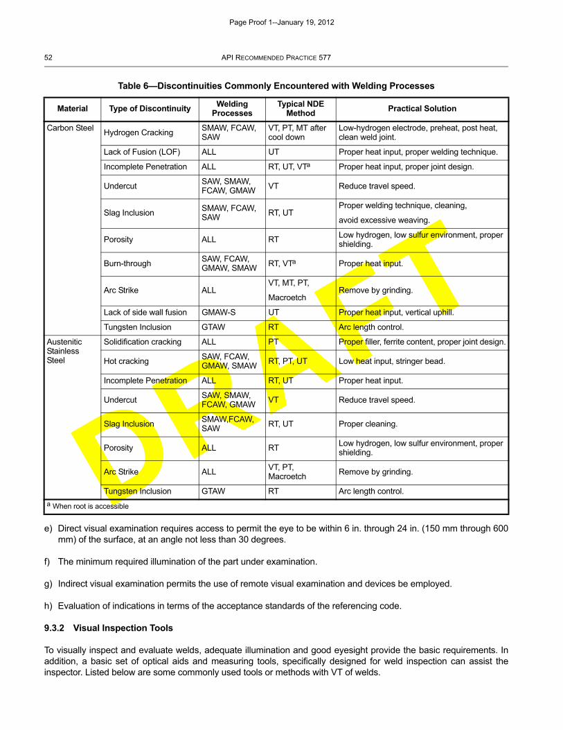
DRAFT
52 API RECOMMENDED PRACTICE 577
e) Direct visual examination requires access to permit the eye to be within 6 in. through 24 in. (150 mm through 600mm) of the surface, at an angle not less than 30 degrees.
f) The minimum required illumination of the part under examination.
g) Indirect visual examination permits the use of remote visual examination and devices be employed.
h) Evaluation of indications in terms of the acceptance standards of the referencing code.
9.3.2 Visual Inspection Tools
To visually inspect and evaluate welds, adequate illumination and good eyesight provide the basic requirements. Inaddition, a basic set of optical aids and measuring tools, specifically designed for weld inspection can assist theinspector. Listed below are some commonly used tools or methods with VT of welds.
Table 6—Discontinuities Commonly Encountered with Welding Processes
Material Type of Discontinuity Welding Processes
Typical NDE Method
Practical Solution
Carbon SteelHydrogen Cracking
SMAW, FCAW, SAW
VT, PT, MT after cool down
Low-hydrogen electrode, preheat, post heat, clean weld joint.
Lack of Fusion (LOF) ALL UT Proper heat input, proper welding technique.
Incomplete Penetration ALL RT, UT, VTa Proper heat input, proper joint design.
UndercutSAW, SMAW, FCAW, GMAW VT Reduce travel speed.
Slag Inclusion SMAW, FCAW, SAW RT, UT
Proper welding technique, cleaning,
avoid excessive weaving.
Porosity ALL RT Low hydrogen, low sulfur environment, proper shielding.
Burn-throughSAW, FCAW, GMAW, SMAW RT, VTa Proper heat input.
Arc Strike ALLVT, MT, PT,
MacroetchRemove by grinding.
Lack of side wall fusion GMAW-S UT Proper heat input, vertical uphill.
Tungsten Inclusion GTAW RT Arc length control.
Austenitic Stainless Steel
Solidification cracking ALL PT Proper filler, ferrite content, proper joint design.
Hot cracking SAW, FCAW, GMAW, SMAW
RT, PT, UT Low heat input, stringer bead.
Incomplete Penetration ALL RT, UT Proper heat input.
Undercut SAW, SMAW, FCAW, GMAW
VT Reduce travel speed.
Slag InclusionSMAW,FCAW, SAW RT, UT Proper cleaning.
Porosity ALL RT Low hydrogen, low sulfur environment, proper shielding.
Arc Strike ALL VT, PT, Macroetch
Remove by grinding.
Tungsten Inclusion GTAW RT Arc length control.
a When root is accessible
Page Proof 1--January 19, 2012
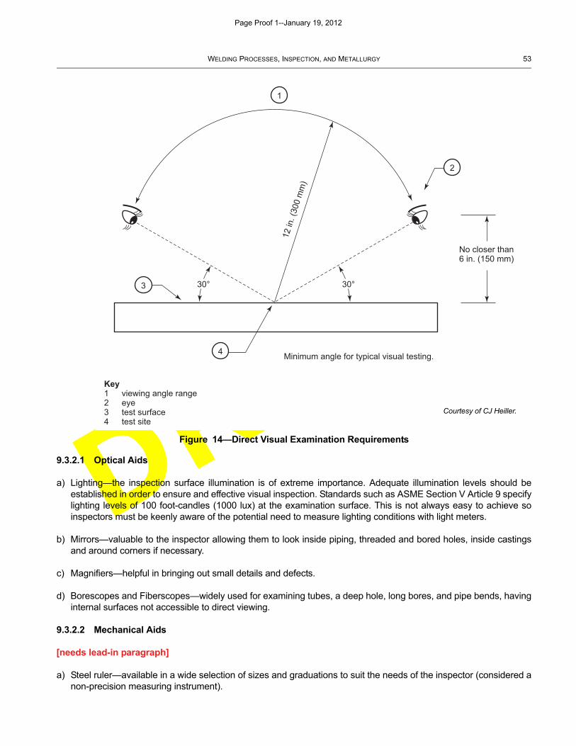
DRAFT
WELDING PROCESSES, INSPECTION, AND METALLURGY 53
9.3.2.1 Optical Aids
a) Lighting—the inspection surface illumination is of extreme importance. Adequate illumination levels should beestablished in order to ensure and effective visual inspection. Standards such as ASME Section V Article 9 specifylighting levels of 100 foot-candles (1000 lux) at the examination surface. This is not always easy to achieve soinspectors must be keenly aware of the potential need to measure lighting conditions with light meters.
b) Mirrors—valuable to the inspector allowing them to look inside piping, threaded and bored holes, inside castingsand around corners if necessary.
c) Magnifiers—helpful in bringing out small details and defects.
d) Borescopes and Fiberscopes—widely used for examining tubes, a deep hole, long bores, and pipe bends, havinginternal surfaces not accessible to direct viewing.
9.3.2.2 Mechanical Aids
[needs lead-in paragraph]
a) Steel ruler—available in a wide selection of sizes and graduations to suit the needs of the inspector (considered anon-precision measuring instrument).
Figure 14—Direct Visual Examination Requirements
30° 30°
No closer than6 in. (150 mm)
Minimum angle for typical visual testing.
12 in
. (30
0 m
m)
Key1 viewing angle range2 eye3 test surface4 test site
1
2
3
4
Courtesy of CJ Heiller.
Page Proof 1--January 19, 2012
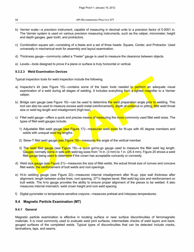
DRAFT
54 API RECOMMENDED PRACTICE 577
b) Vernier scale—a precision instrument, capable of measuring in decimal units to a precision factor of 0.0001 in.The Vernier system is used on various precision measuring instruments, such as the caliper, micrometer, heightand depth gauges, gear tooth, and protractors.
c) Combination square set—consisting of a blade and a set of three heads: Square, Center, and Protractor. Useduniversally in mechanical work for assembly and layout examination.
d) Thickness gauge—commonly called a “Feeler” gauge is used to measure the clearance between objects.
e) Levels—tools designed to prove if a plane or surface is truly horizontal or vertical.
9.3.2.3 Weld Examination Devices
Typical inspection tools for weld inspection include the following.
a) Inspector’s kit (see Figure 15)—contains some of the basic tools needed to perform an adequate visualexamination of a weld during all stages of welding. It includes everything from a lighted magnifier to a Verniercaliper.
b) Bridge cam gauge (see Figure 16)—can be used to determine the weld preparation angle prior to welding. Thistool can also be used to measure excess weld metal (reinforcement), depth of undercut or pitting, fillet weld throatsize or weld leg length and misalignment (high-low).
c) Fillet weld gauge—offers a quick and precise means of measuring the more commonly used fillet weld sizes. Thetypes of fillet weld gauges include.
1) Adjustable fillet weld gauge (see Figure 17)—measures weld sizes for fit-ups with 45 degree members andwelds with unequal weld leg lengths.
2) Skew-T fillet weld gauge (see Figure 18)—measures the angle of the vertical member.
3) The weld fillet gauge (see Figure 19)—a quick go/no-go gauge used to measure the fillet weld leg length.Gauges normally come in sets with weld leg sizes from 1/8 in. (3 mm) to 1 in. (25.4 mm). Figure 20 shows a weldfillet gauge being used to determine if the crown has acceptable concavity or convexity.
d) Weld size gauge (see Figure 21)—measures the size of fillet welds, the actual throat size of convex and concavefillet welds, the reinforcement of butt welds and root openings.
e) Hi-lo welding gauge (see Figure 22)—measures internal misalignment after fit-up, pipe wall thickness afteralignment, length between scribe lines, root opening, 371/2 degree bevel, fillet weld leg size and reinforcement onbutt welds. The hi-lo gauge provides the ability to ensure proper alignment of the pieces to be welded. It alsomeasures internal mismatch, weld crown height and root weld spacing.
f) Digital pyrometer or temperature sensitive crayons—measures preheat and interpass temperatures.
9.4 Magnetic Particle Examination (MT)
9.4.1 General
Magnetic particle examination is effective in locating surface or near surface discontinuities of ferromagneticmaterials. It is most commonly used to evaluate weld joint surfaces, intermediate checks of weld layers and back-gouged surfaces of the completed welds. Typical types of discontinuities that can be detected include cracks,laminations, laps, and seams.
Page Proof 1--January 19, 2012
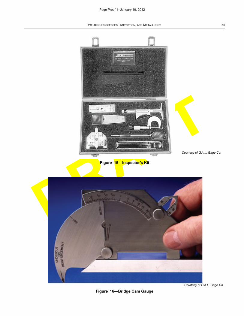
DRAFT
WELDING PROCESSES, INSPECTION, AND METALLURGY 55
Figure 15—Inspector’s Kit
Figure 16—Bridge Cam Gauge
Courtesy of G.A.I., Gage Co.
Courtesy of G.A.I., Gage Co.
Page Proof 1--January 19, 2012
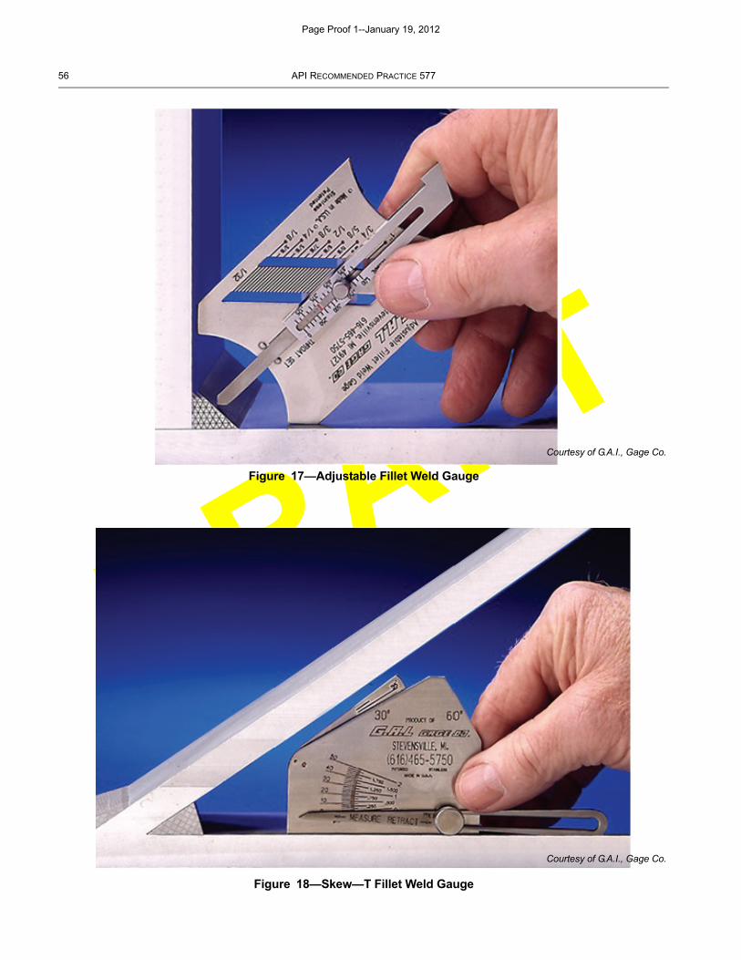
DRAFT
56 API RECOMMENDED PRACTICE 577
Figure 17—Adjustable Fillet Weld Gauge
Figure 18—Skew—T Fillet Weld Gauge
Courtesy of G.A.I., Gage Co.
Courtesy of G.A.I., Gage Co.
Page Proof 1--January 19, 2012
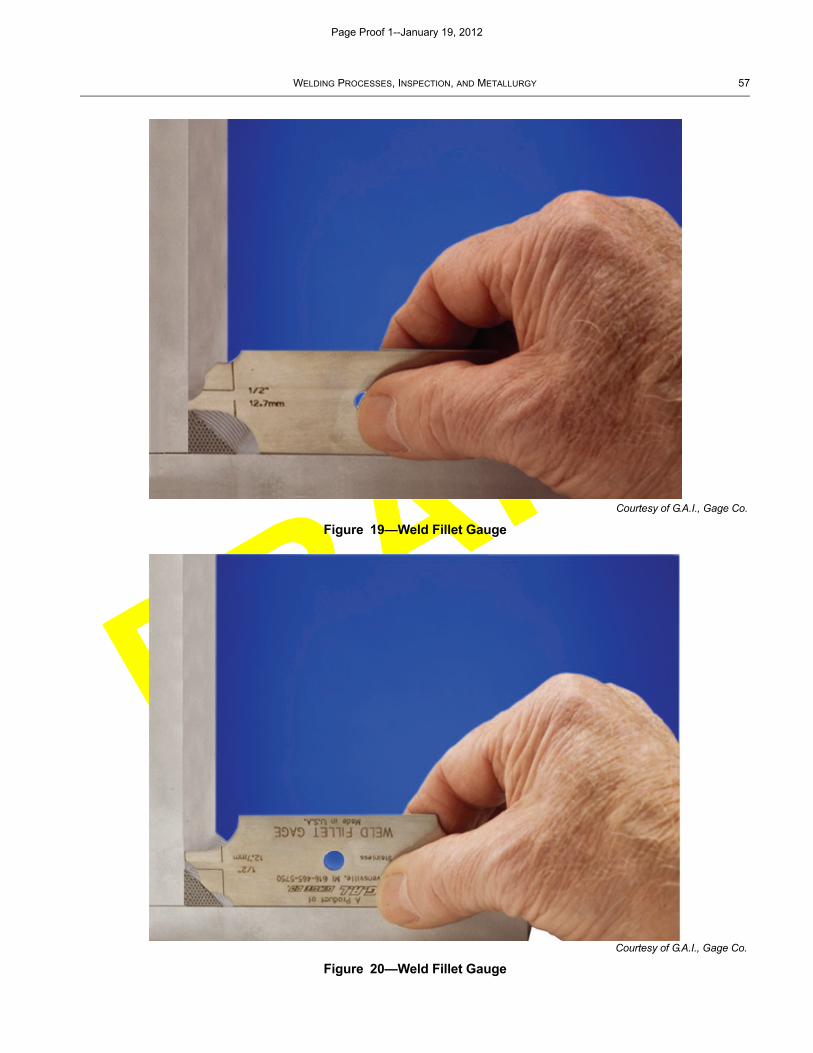
DRAFT
WELDING PROCESSES, INSPECTION, AND METALLURGY 57
Figure 19—Weld Fillet Gauge
Figure 20—Weld Fillet Gauge
Courtesy of G.A.I., Gage Co.
Courtesy of G.A.I., Gage Co.
Page Proof 1--January 19, 2012
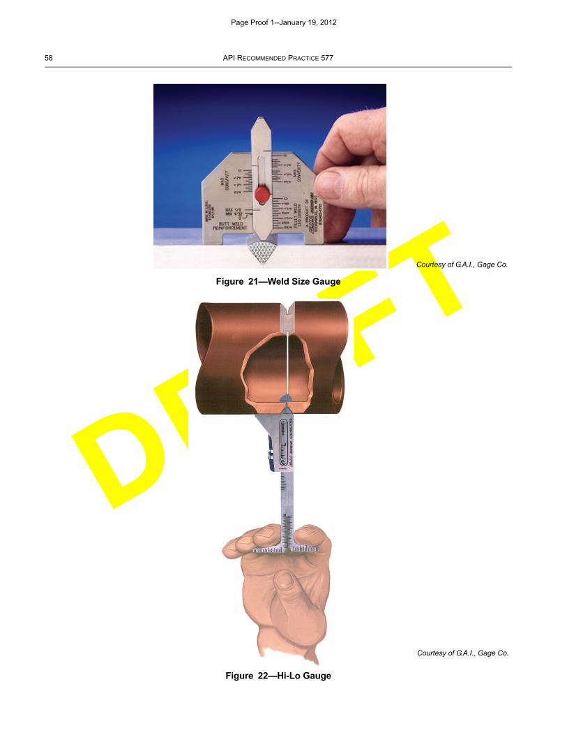
DRAFT
58 API RECOMMENDED PRACTICE 577
Figure 21—Weld Size Gauge
Figure 22—Hi-Lo Gauge
Courtesy of G.A.I., Gage Co.
Courtesy of G.A.I., Gage Co.
Page Proof 1--January 19, 2012
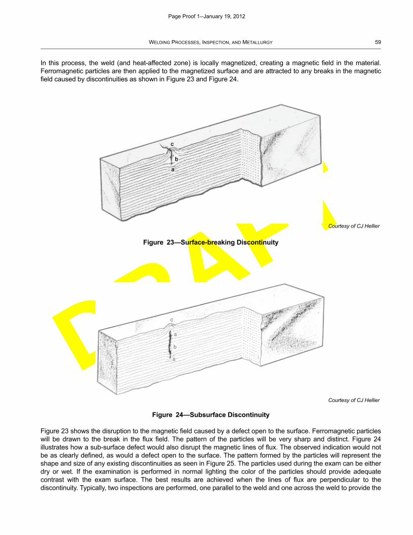
DRAFT
WELDING PROCESSES, INSPECTION, AND METALLURGY 59
In this process, the weld (and heat-affected zone) is locally magnetized, creating a magnetic field in the material.Ferromagnetic particles are then applied to the magnetized surface and are attracted to any breaks in the magneticfield caused by discontinuities as shown in Figure 23 and Figure 24.
Figure 23 shows the disruption to the magnetic field caused by a defect open to the surface. Ferromagnetic particleswill be drawn to the break in the flux field. The pattern of the particles will be very sharp and distinct. Figure 24illustrates how a sub-surface defect would also disrupt the magnetic lines of flux. The observed indication would notbe as clearly defined, as would a defect open to the surface. The pattern formed by the particles will represent theshape and size of any existing discontinuities as seen in Figure 25. The particles used during the exam can be eitherdry or wet. If the examination is performed in normal lighting the color of the particles should provide adequatecontrast with the exam surface. The best results are achieved when the lines of flux are perpendicular to thediscontinuity. Typically, two inspections are performed, one parallel to the weld and one across the weld to provide the
Figure 23—Surface-breaking Discontinuity
Figure 24—Subsurface Discontinuity
Courtesy of CJ Hellier
Courtesy of CJ Hellier
Page Proof 1--January 19, 2012
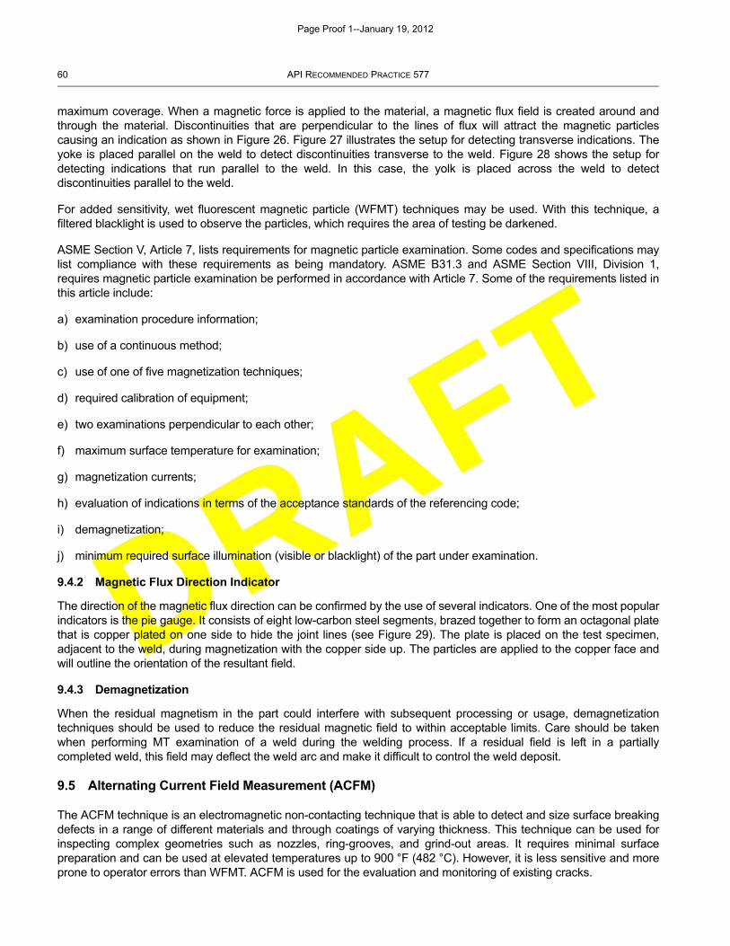
DRAFT
60 API RECOMMENDED PRACTICE 577
maximum coverage. When a magnetic force is applied to the material, a magnetic flux field is created around andthrough the material. Discontinuities that are perpendicular to the lines of flux will attract the magnetic particlescausing an indication as shown in Figure 26. Figure 27 illustrates the setup for detecting transverse indications. Theyoke is placed parallel on the weld to detect discontinuities transverse to the weld. Figure 28 shows the setup fordetecting indications that run parallel to the weld. In this case, the yolk is placed across the weld to detectdiscontinuities parallel to the weld.
For added sensitivity, wet fluorescent magnetic particle (WFMT) techniques may be used. With this technique, afiltered blacklight is used to observe the particles, which requires the area of testing be darkened.
ASME Section V, Article 7, lists requirements for magnetic particle examination. Some codes and specifications maylist compliance with these requirements as being mandatory. ASME B31.3 and ASME Section VIII, Division 1,requires magnetic particle examination be performed in accordance with Article 7. Some of the requirements listed inthis article include:
a) examination procedure information;
b) use of a continuous method;
c) use of one of five magnetization techniques;
d) required calibration of equipment;
e) two examinations perpendicular to each other;
f) maximum surface temperature for examination;
g) magnetization currents;
h) evaluation of indications in terms of the acceptance standards of the referencing code;
i) demagnetization;
j) minimum required surface illumination (visible or blacklight) of the part under examination.
9.4.2 Magnetic Flux Direction Indicator
The direction of the magnetic flux direction can be confirmed by the use of several indicators. One of the most popularindicators is the pie gauge. It consists of eight low-carbon steel segments, brazed together to form an octagonal platethat is copper plated on one side to hide the joint lines (see Figure 29). The plate is placed on the test specimen,adjacent to the weld, during magnetization with the copper side up. The particles are applied to the copper face andwill outline the orientation of the resultant field.
9.4.3 Demagnetization
When the residual magnetism in the part could interfere with subsequent processing or usage, demagnetizationtechniques should be used to reduce the residual magnetic field to within acceptable limits. Care should be takenwhen performing MT examination of a weld during the welding process. If a residual field is left in a partiallycompleted weld, this field may deflect the weld arc and make it difficult to control the weld deposit.
9.5 Alternating Current Field Measurement (ACFM)
The ACFM technique is an electromagnetic non-contacting technique that is able to detect and size surface breakingdefects in a range of different materials and through coatings of varying thickness. This technique can be used forinspecting complex geometries such as nozzles, ring-grooves, and grind-out areas. It requires minimal surfacepreparation and can be used at elevated temperatures up to 900 °F (482 °C). However, it is less sensitive and moreprone to operator errors than WFMT. ACFM is used for the evaluation and monitoring of existing cracks.
Page Proof 1--January 19, 2012
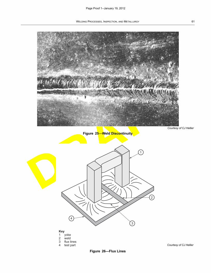
DRAFT
WELDING PROCESSES, INSPECTION, AND METALLURGY 61
Figure 25—Weld Discontinuity
Figure 26—Flux Lines
Courtesy of CJ Hellier
Key1 yoke2 weld3 flux lines4 test part
1
2
34
Courtesy of CJ Hellier
Page Proof 1--January 19, 2012

DRAFT
62 API RECOMMENDED PRACTICE 577
Figure 27—Detecting Discontinuities Transverse to Weld
Figure 28—Detecting Discontinuities Parallel to the Weld
Courtesy of CJ Hellier
Courtesy of CJ Hellier
Page Proof 1--January 19, 2012
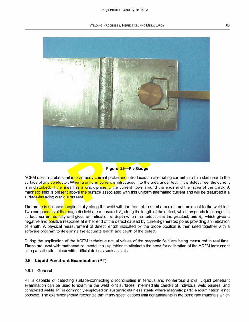
DRAFT
WELDING PROCESSES, INSPECTION, AND METALLURGY 63
ACFM uses a probe similar to an eddy current probe and introduces an alternating current in a thin skin near to thesurface of any conductor. When a uniform current is introduced into the area under test, if it is defect free, the currentis undisturbed. If the area has a crack present, the current flows around the ends and the faces of the crack. Amagnetic field is present above the surface associated with this uniform alternating current and will be disturbed if asurface-breaking crack is present.
The probe is scanned longitudinally along the weld with the front of the probe parallel and adjacent to the weld toe.Two components of the magnetic field are measured: Bx along the length of the defect, which responds to changes insurface current density and gives an indication of depth when the reduction is the greatest; and Bz, which gives anegative and positive response at either end of the defect caused by current-generated poles providing an indicationof length. A physical measurement of defect length indicated by the probe position is then used together with asoftware program to determine the accurate length and depth of the defect.
During the application of the ACFM technique actual values of the magnetic field are being measured in real time.These are used with mathematical model look-up tables to eliminate the need for calibration of the ACFM instrumentusing a calibration piece with artificial defects such as slots.
9.6 Liquid Penetrant Examination (PT)
9.6.1 General
PT is capable of detecting surface-connecting discontinuities in ferrous and nonferrous alloys. Liquid penetrantexamination can be used to examine the weld joint surfaces, intermediate checks of individual weld passes, andcompleted welds. PT is commonly employed on austenitic stainless steels where magnetic particle examination is notpossible. The examiner should recognize that many specifications limit contaminants in the penetrant materials which
Figure 29—Pie Gauge
Page Proof 1--January 19, 2012
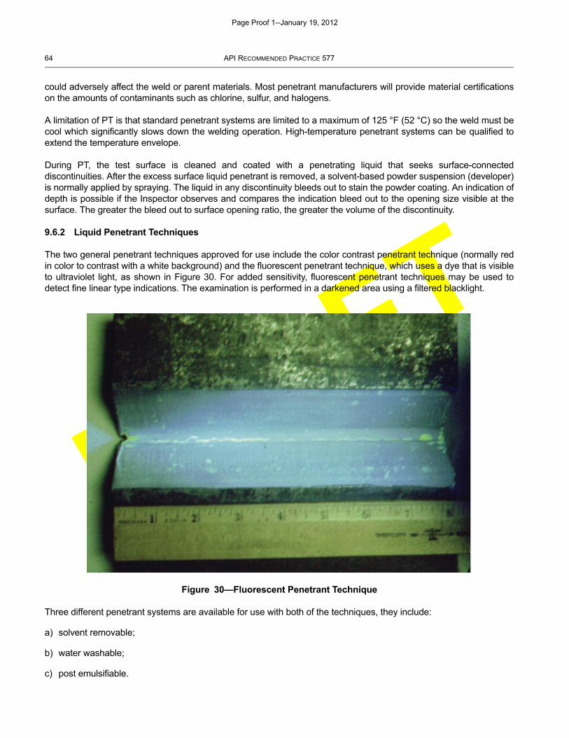
DRAFT
64 API RECOMMENDED PRACTICE 577
could adversely affect the weld or parent materials. Most penetrant manufacturers will provide material certificationson the amounts of contaminants such as chlorine, sulfur, and halogens.
A limitation of PT is that standard penetrant systems are limited to a maximum of 125 °F (52 °C) so the weld must becool which significantly slows down the welding operation. High-temperature penetrant systems can be qualified toextend the temperature envelope.
During PT, the test surface is cleaned and coated with a penetrating liquid that seeks surface-connecteddiscontinuities. After the excess surface liquid penetrant is removed, a solvent-based powder suspension (developer)is normally applied by spraying. The liquid in any discontinuity bleeds out to stain the powder coating. An indication ofdepth is possible if the Inspector observes and compares the indication bleed out to the opening size visible at thesurface. The greater the bleed out to surface opening ratio, the greater the volume of the discontinuity.
9.6.2 Liquid Penetrant Techniques
The two general penetrant techniques approved for use include the color contrast penetrant technique (normally redin color to contrast with a white background) and the fluorescent penetrant technique, which uses a dye that is visibleto ultraviolet light, as shown in Figure 30. For added sensitivity, fluorescent penetrant techniques may be used todetect fine linear type indications. The examination is performed in a darkened area using a filtered blacklight.
Three different penetrant systems are available for use with both of the techniques, they include:
a) solvent removable;
b) water washable;
c) post emulsifiable.
Figure 30—Fluorescent Penetrant Technique
Page Proof 1--January 19, 2012
DRAFT
WELDING PROCESSES, INSPECTION, AND METALLURGY 65
Compatibility with base metals, welds, and process material should be considered before penetrants are used, sincethey can be difficult to remove completely.
ASME Section V, Article 6, (Paragraph T-620) lists general requirements for liquid penetrant examination. Codes andspecifications may list compliance with these requirements as mandatory. API Standard 650, ASME B31.3 and ASMESection VIII, Division 1, require liquid penetrant examination be performed in accordance with Article 6. Somerequirements listed in this article include:
a) inspection is to be performed in accordance with a procedure (as specified by the referencing code section);
b) type of penetrant materials to be used;
c) details for pre-examination cleaning including minimum drying time;
d) dwell time for the penetrant;
e) details for removing excess penetrant, applying the developer, and time before interpretation;
f) evaluation of indications in terms of the acceptance standards of the referencing code;
g) post examination cleaning requirements;
h) minimum required surface illumination (visible or blacklight) of the part under examination.
9.7 Eddy Current Examination (ET)
Eddy current inspection is used to detect surface discontinuities, and in some cases subsurface discontinuities intubing, pipe, wire, rod and bar stock. ET has limited use in weld inspection. Eddy current can be used as a quick testto ensure that the components being joined during welding have the same material properties, and as a quick checkfor defects of the weld joint faces. It can also be used to measure the thickness of protective, nonconductive surfacecoatings and measure cladding thickness.
Eddy current uses a magnetic field to create circulating currents in electrically conductive material. Discontinuities inthe material will alter the magnetically induced fields and present them on the unit’s display. As with the magneticparticle inspection, this technique is most sensitive for defect detection when the currents are perpendicular to thediscontinuity.
More information can be found in ASME Section V, Article 8, which addresses eddy current examination of tubularproducts.
9.8 Radiographic Examination (RT)
9.8.1 General
RT is a volumetric examination method capable of examining the entire specimen rather than just the surface. It is thehistorical approach to examine completed welds for surface and subsurface discontinuities. The method uses thechange in absorption of radiation by solid metal and in an areas of a discontinuity. The radiation transmitted reactswith the film, a latent image is captured, and when the film is processed (developed) creates a permanent image(radiograph) of the weld. Some methods are available which use electronics to create a digital image and are referredto as “filmless.” Due to the hazard of radiation, and the licensing requirements, the cost can be higher and the trainedand certified personnel more limited, than with other NDE methods.
An NDT examiner interprets and evaluates the radiographs for differences in absorption and transmission results.Radiographic indications display a different density as contrasted with the normal background image of the weld or
Page Proof 1--January 19, 2012
DRAFT
66 API RECOMMENDED PRACTICE 577
part being inspected. The radiographer also makes sure that the film is exposed by the primary source of the radiationand not backscatter radiation.
The NDT examiner that performs the film interpretation, evaluation and reporting should be certified as a minimum toASNT Level II requirements. However, all personnel performing radiography are required to attend radiation safetytraining and comply with the applicable regulatory requirements.
ASME Section V, Article 2, paragraph T-220 lists the general requirements for radiographic examination. There arevery specific requirements with regard to the quality of the produced radiograph, including the sharpness of theimage, the ability to prove adequate film density in the area of interest and sensitivity to the size and type of expectedflaws. Requirements listed in Article 2 include:
a) method to determine if backscatter is present;
b) permanent identification, traceable to the component;
c) film selection in accordance with SE-1815;
d) designations for hole or wire type image quality indicators (penetrameters);
e) suggested radiographic techniques;
f) facilities for viewing radiographs;
g) calibration (certification of source size).
The exposure and processing of a radiograph is considered acceptable when it meets the required quality features interms of sensitivity and density. These factors are designed to ensure that imperfections of a dimension relative tosection thickness will be revealed.
9.8.2 Image Quality Indicators (Penetrameters)
Standards for industrial radiography require the use of one or more image quality indicators (IQIs) to determine therequired sensitivity is achieved. The IQI was previously called a penetrameter but this term is no longer being used inmost codes. To assess sensitivity the required hole or wire as specified by the governing code must be visible on thefinished radiograph. Mistakes with IQIs (penetrameters) can have much greater impact on thinner wall pipe wherelarge root pass imperfections can significantly reduce the strength and integrity of a weld.
IQIs (penetrameters) are tools used in industrial radiography to establish the quality level of the radiographictechnique. IQIs (penetrameters) are selected based on the following.
a) Material being radiographed. The IQI must be made from the same alloy material group or one with less radiationabsorption.
b) Thickness of the base material plus reinforcement. The thickness of any backing ring or strip is not a considerationin IQI selection.
There are two types of IQIs (penetrameters) in use today.
1) Wire-type IQIs (penetrameters) are constructed of an array of six paralleled wires of specified diameters. Theyare made of substantially the same material as the component being radiographed. Wire-type IQIs(penetrameters) are placed on and perpendicular to the weld prior to the exposure of a radiograph. Thediameter of the smallest wire that is visible as a lighter-white image on the radiograph provides an indication ofthe sensitivity of the radiograph. The wire that is to be visible on an acceptable radiograph is known as the
Page Proof 1--January 19, 2012
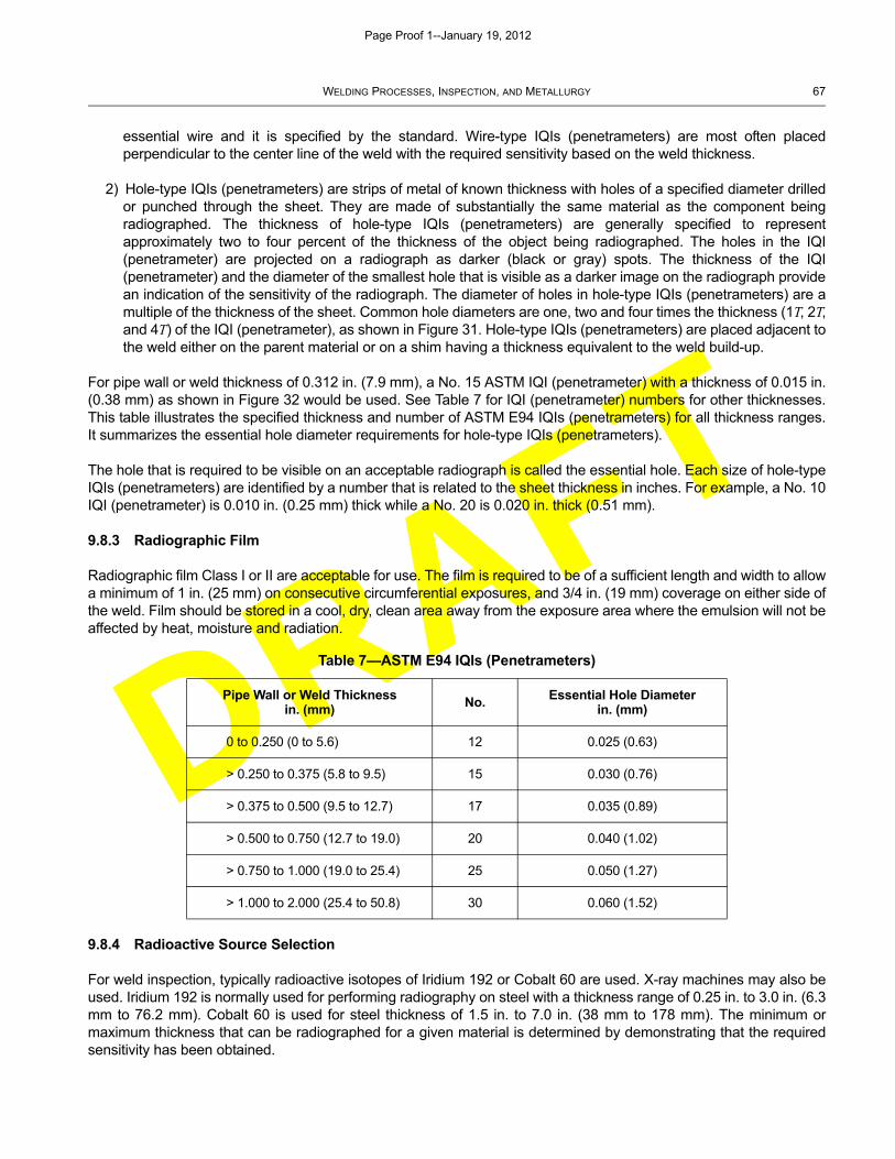
DRAFT
WELDING PROCESSES, INSPECTION, AND METALLURGY 67
essential wire and it is specified by the standard. Wire-type IQIs (penetrameters) are most often placedperpendicular to the center line of the weld with the required sensitivity based on the weld thickness.
2) Hole-type IQIs (penetrameters) are strips of metal of known thickness with holes of a specified diameter drilledor punched through the sheet. They are made of substantially the same material as the component beingradiographed. The thickness of hole-type IQIs (penetrameters) are generally specified to representapproximately two to four percent of the thickness of the object being radiographed. The holes in the IQI(penetrameter) are projected on a radiograph as darker (black or gray) spots. The thickness of the IQI(penetrameter) and the diameter of the smallest hole that is visible as a darker image on the radiograph providean indication of the sensitivity of the radiograph. The diameter of holes in hole-type IQIs (penetrameters) are amultiple of the thickness of the sheet. Common hole diameters are one, two and four times the thickness (1T, 2T,and 4T) of the IQI (penetrameter), as shown in Figure 31. Hole-type IQIs (penetrameters) are placed adjacent tothe weld either on the parent material or on a shim having a thickness equivalent to the weld build-up.
For pipe wall or weld thickness of 0.312 in. (7.9 mm), a No. 15 ASTM IQI (penetrameter) with a thickness of 0.015 in.(0.38 mm) as shown in Figure 32 would be used. See Table 7 for IQI (penetrameter) numbers for other thicknesses.This table illustrates the specified thickness and number of ASTM E94 IQIs (penetrameters) for all thickness ranges.It summarizes the essential hole diameter requirements for hole-type IQIs (penetrameters).
The hole that is required to be visible on an acceptable radiograph is called the essential hole. Each size of hole-typeIQIs (penetrameters) are identified by a number that is related to the sheet thickness in inches. For example, a No. 10IQI (penetrameter) is 0.010 in. (0.25 mm) thick while a No. 20 is 0.020 in. thick (0.51 mm).
9.8.3 Radiographic Film
Radiographic film Class I or II are acceptable for use. The film is required to be of a sufficient length and width to allowa minimum of 1 in. (25 mm) on consecutive circumferential exposures, and 3/4 in. (19 mm) coverage on either side ofthe weld. Film should be stored in a cool, dry, clean area away from the exposure area where the emulsion will not beaffected by heat, moisture and radiation.
9.8.4 Radioactive Source Selection
For weld inspection, typically radioactive isotopes of Iridium 192 or Cobalt 60 are used. X-ray machines may also beused. Iridium 192 is normally used for performing radiography on steel with a thickness range of 0.25 in. to 3.0 in. (6.3mm to 76.2 mm). Cobalt 60 is used for steel thickness of 1.5 in. to 7.0 in. (38 mm to 178 mm). The minimum ormaximum thickness that can be radiographed for a given material is determined by demonstrating that the requiredsensitivity has been obtained.
Table 7—ASTM E94 IQIs (Penetrameters)
Pipe Wall or Weld Thicknessin. (mm) No. Essential Hole Diameter
in. (mm)
0 to 0.250 (0 to 5.6) 12 0.025 (0.63)
> 0.250 to 0.375 (5.8 to 9.5) 15 0.030 (0.76)
> 0.375 to 0.500 (9.5 to 12.7) 17 0.035 (0.89)
> 0.500 to 0.750 (12.7 to 19.0) 20 0.040 (1.02)
> 0.750 to 1.000 (19.0 to 25.4) 25 0.050 (1.27)
> 1.000 to 2.000 (25.4 to 50.8) 30 0.060 (1.52)
Page Proof 1--January 19, 2012
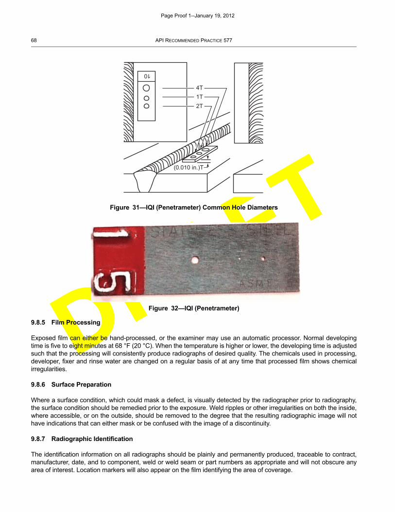
DRAFT
68 API RECOMMENDED PRACTICE 577
9.8.5 Film Processing
Exposed film can either be hand-processed, or the examiner may use an automatic processor. Normal developingtime is five to eight minutes at 68 °F (20 °C). When the temperature is higher or lower, the developing time is adjustedsuch that the processing will consistently produce radiographs of desired quality. The chemicals used in processing,developer, fixer and rinse water are changed on a regular basis of at any time that processed film shows chemicalirregularities.
9.8.6 Surface Preparation
Where a surface condition, which could mask a defect, is visually detected by the radiographer prior to radiography,the surface condition should be remedied prior to the exposure. Weld ripples or other irregularities on both the inside,where accessible, or on the outside, should be removed to the degree that the resulting radiographic image will nothave indications that can either mask or be confused with the image of a discontinuity.
9.8.7 Radiographic Identification
The identification information on all radiographs should be plainly and permanently produced, traceable to contract,manufacturer, date, and to component, weld or weld seam or part numbers as appropriate and will not obscure anyarea of interest. Location markers will also appear on the film identifying the area of coverage.
Figure 31—IQI (Penetrameter) Common Hole Diameters
Figure 32—IQI (Penetrameter)
10
4T1T2T
(0.010 in.)T
Page Proof 1--January 19, 2012

DRAFT
WELDING PROCESSES, INSPECTION, AND METALLURGY 69
9.8.8 Radiographic Techniques
9.8.8.1 General
The most effective technique is one in which the radiation passes through a single thickness of the material beingradiographed and the film is in contact with the surface opposite the source side. Other techniques may be used asthe referencing code or situation dictates. Regardless of the technique used, the goal is to achieve the highestpossible quality level. The IQI (penetrameter) placement should be as close to the weld as possible without interferingwith the weld image.
A technique should be chosen based upon its ability to produce images of suspected discontinuities, especially thosethat may not be oriented in a favorable direction to the radiation source. Radiography is extremely sensitive to theorientation of tight planar discontinuities. If a tight planar discontinuity is expected to be at an angle to the source ofthe radiation, it will be difficult or impossible to detect. The nature, location, and orientation should always be a majorfactor in establishing the technique.
9.8.8.2 Single-wall Technique
A single-wall exposure technique should be used for radiography whenever practical. In the single-wall technique, theradiation passes through only one wall of the material or weld, which is viewed for acceptance on the radiograph (seeFigure 33). An adequate number of exposures should be made to demonstrate that the required coverage has beenobtained.
9.8.8.3 Single-wall Viewing
For materials, and for welds in components, a technique may be used in which the radiation passes through two wallsand only the weld (material) on the film sidewall is viewed for acceptance. An adequate number of exposures shouldbe made to demonstrate that the required coverage is met for circumferential welds (materials). A minimum of threeexposures taken at 120 degrees to each other should be made.
9.8.8.4 Double-wall Technique
When it is not practical to use a single wall technique, a double-wall technique should be used.
For materials and for welds in components 3.5 in. (88.9 mm) or less in nominal outside diameter, a technique may beused in which the radiation passes through two walls and the weld (material) in both walls is viewed for acceptance onthe same radiograph. For double-wall viewing of welds, the radiation beam may be offset from the plane of the weld atan angle sufficient to separate the images of the source side portions and the film side portions of the weld so there isno overlap of the areas to be interpreted (see Figure 34). When complete coverage is required, a minimum of twoexposures taken at 90 degrees to each other should be made of each weld joint.
Alternatively, the weld may be radiographed with the radiation beam positioned such that both walls aresuperimposed. When complete coverage is required, a minimum of three exposures taken at either 60 degrees or120 degrees to each other should be made for each weld joint.
9.8.9 Evaluation of Radiographs
9.8.9.1 General
The final step in the radiographic process is the evaluation of the radiograph. Accurate film interpretation is essential;it requires hours of reviewing and the understanding of the different types of images and conditions associated inindustrial radiography. The interpreter should be aware of different welding processes and the discontinuitiesassociated with those processes. The various discontinuities found in weldments may not always be readilydetectable. For example, rounded indications such as porosity, slag and inclusions will be more apparent than an
Page Proof 1--January 19, 2012

DRAFT
70 API RECOMMENDED PRACTICE 577
indication from a crack, lack of fusion or overlap. A weld crack is generally tight and not always detectable byradiography unless their orientation is somewhat in the same plane as the direction of the radiation. Lack of fusion istypically narrow and linear and it tends to be straighter than a crack. In many cases lack of fusion is located at theweld bevel angle or between two subsequent weld bead passes. This may add to the degree of difficulty in identifyingthis condition.
9.8.9.2 Facilities for Viewing Radiographs
Viewing facilities will provide subdued background lighting of an intensity that will not cause troublesome reflections,shadows, or glare on the radiograph. Equipment used to view radiographs for interpretation will provide a light sourcesufficient for the essential IQI (penetrameter) hole or wire to be visible for the specified density range. The viewing
Figure 33—Single-wall Techniques
Figure 34—Double-wall Techniques
Source
Film
Source SourceSource
Film
Film
Source
Film
Source
Film
Source
Film
Source
Courtesy of Charles J. Heller
Superimposed
Film
Ellipse
Film
Page Proof 1--January 19, 2012
DRAFT
WELDING PROCESSES, INSPECTION, AND METALLURGY 71
conditions should be such that the light from around the outer edge of the radiograph or coming through low-densityportions of the radiographs does not interfere with the interpretation. Low power magnification devices (1.5X to 3X)may also be used to aid in film interpretation and evaluation; but too high of a magnification will also enhance thegraininess of the film. For example, comparators with scales etched into the glass offer magnification and measuringcapabilities.
9.8.9.3 Quality of Radiographs
Radiographs should be free from mechanical, chemical or other blemishes to the extent that they do not mask, andare not confused with the image of any discontinuity in the area of interest. A radiograph with any blemishes in thearea of interest should be discarded and the area radiographed again.
Definition of the area of interest is often commonly misunderstood and the subject of confusion. Many of the commoncodes and standards in the hydrocarbon industry do not actually define the area of interest which leads tomisalignment between inspectors and fabricators. ASTM E1316 states “the specific portion of a radiograph thatneeds to be evaluated”. This is the approach inspectors generally prefer, and gives the inspector the final decision toidentify the area of interest. ASME Section XI for the nuclear industry has a more practical guidance of 1t where t isthe nominal thickness of the component being joined. This provides a minimum recommended guidance forinspectors reviewing radiographs.
9.8.9.4 Radiographic Density
Film density is the quantitative measure of film blackening as a result of exposure and processing. Clear film has azero density value. Exposed film that allows 10 % of the incident light to pass through has a 1.0 film density. A filmdensity of 2.0, 3.0, and 4.0 allows 1 %, 0.1 % and 0.01 % of the incident light to pass through respectively.
The transmitted film density through the radiographic image through the body of the hole type IQI (penetrameter), oradjacent to the wire IQI (penetrameter), in the area of interest should be within the range 1.8 to 4.0 for x-ray and 2.0 to4.0 for Gamma Ray. Adequate radiographic density is essential; rejectable conditions in a weld may go unnoticed ifslight density variations in the radiographs are not observed.
A densitometer or step wedge comparison film is used to measure and estimate the darkness (density) of the film. Adensitometer is an electronic instrument calibrated using a step tablet or step wedge calibration film traceable to anational standard. The step wedge comparison film is a step wedge that has been calibrated by comparison to acalibrated densitometer.
The base density of the radiograph is measured through the IQI (penetrameter). A number of density readings shouldbe taken at random locations in the area of interest (excluding areas having discontinuities). The density range in thearea of interest must not vary greater or less than a specified percentage of the base density as defined in the code orspecification.
9.8.9.5 Excessive Backscatter
Radiation that passes through the object and film can be reflected back towards the film (i.e. a phenomenon termed‘backscatter’). A lead letter “B” with a minimum dimension of 1/2 in. (12.7 mm) and 1/16 in. (1.55 mm) thickness istypically attached to the back of each film holder/cassette during each exposure to determine if backscatter radiationis exposing the film. If a light image of the letter “B” appears on any radiograph of a darker background, protectionfrom scatter radiation will be considered insufficient and the radiograph will be considered unacceptable. A darkimage of the “B” on a lighter background is not cause for rejection of the radiograph.
There is a common misconception by those not trained in industrial radiography that the letter “B” will always appearon a radiograph. This is in fact not correct. Where there is no medium besides free air to cause backscatter, there willbe insufficient radiation back to the film or imaging device to produce an image.
Page Proof 1--January 19, 2012
DRAFT
72 API RECOMMENDED PRACTICE 577
9.8.9.6 Interpretation
Radiographic interpretation is the skill of extracting the maximum information from a radiographic image. Thisrequires subjective judgment by the interpreter and is influenced by the interpreter’s knowledge of:
a) the characteristics of the radiation source and energy level(s) with respect to the material being examined;
b) the characteristics of the recording media in response to the selected radiation source and the energy level(s);
c) the processing of the recording media with respect to the image quality;
d) the product form (object) being radiographed;
e) the possible and most probable types of discontinuities that may occur in the test object;
f) the possible variations of the discontinuities’ images as a function of radiographic geometry, and other factors; and
g) the acceptance criteria that will be applied for accept/reject determination.
Because radiographic interpreters have varying levels of knowledge and experience, training becomes an importantfactor for improving the agreement levels between interpreters. In applications where quality of the final product isimportant for safety and/or reliability, more than one qualified interpreter should evaluate and pass judgment on theradiographs. Figure 35, Figure 36, Figure 37, Figure 38, Figure 39, Figure 40, Figure 41, Figure 42, Figure 43, Figure44, Figure 45, and Figure 46 are radiographic weld images illustrating some typical welding discontinuities anddefects.
9.8.10 Radiographic Examination Records
The information reported is to include, but is not be limited to the following:
a) job/contract number/identification;
b) location marker placement;
c) number of radiographs (exposures);
d) X-ray voltage or isotope type used;
e) X-ray machine focal spot size or isotope physical source size;
f) base material type and thickness, weld reinforcement thickness;
g) source-to-object distance;
h) distance from source side of object to film;
i) film manufacturer and type/designation;
j) number of film in each film holder/cassette;
k) single or double-wall exposure;
l) single or double-wall viewing;
Page Proof 1--January 19, 2012
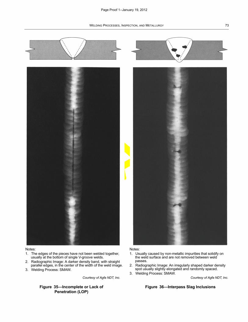
DRAFT
WELDING PROCESSES, INSPECTION, AND METALLURGY 73
Courtesy of Agfa NDT, Inc.
Figure 35—Incomplete or Lack of Penetration (LOP)
Courtesy of Agfa NDT, Inc.
Figure 36—Interpass Slag Inclusions
Notes:1. The edges of the pieces have not been welded together,
usually at the bottom of single V-groove welds.2. Radiographic Image: A darker density band, with straight
parallel edges, in the center of the width of the weld image.3. Welding Process: SMAW.
Notes:1. Usually caused by non-metallic impurities that solidify on
the weld surface and are not removed between weld passes.
2. Radiographic Image: An irregularly shaped darker density spot usually slightly elongated and randomly spaced.
3. Welding Process: SMAW.
Page Proof 1--January 19, 2012
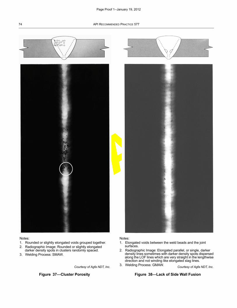
DRAFT
74 API RECOMMENDED PRACTICE 577
Courtesy of Agfa NDT, Inc.
Figure 37—Cluster Porosity
Courtesy of Agfa NDT, Inc.
Figure 38—Lack of Side Wall Fusion
Notes:1. Rounded or slightly elongated voids grouped together.2. Radiographic Image: Rounded or slightly elongated
darker density spots in clusters randomly spaced.3. Welding Process: SMAW.
Notes:1. Elongated voids between the weld beads and the joint
surfaces.2. Radiographic Image: Elongated parallel, or single, darker
density lines sometimes with darker density spots dispersed along the LOF lines which are very straight in the lengthwise direction and not winding like elongated slag lines.
3. Welding Process: GMAW.
Page Proof 1--January 19, 2012
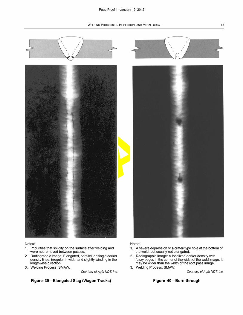
DRAFT
WELDING PROCESSES, INSPECTION, AND METALLURGY 75
Courtesy of Agfa NDT, Inc.
Figure 39—Elongated Slag (Wagon Tracks)
Courtesy of Agfa NDT, Inc.
Figure 40—Burn-through
Notes:1. Impurities that solidify on the surface after welding and
were not removed between passes.2. Radiographic Image: Elongated, parallel, or single darker
density lines, irregular in width and slightly winding in the lengthwise direction.
3. Welding Process: SMAW.
Notes:1. A severe depression or a crater-type hole at the bottom of
the weld, but usually not elongated.2. Radiographic Image: A localized darker density with
fuzzy edges in the center of the width of the weld image. It may be wider than the width of the root pass image.
3. Welding Process: SMAW.
Page Proof 1--January 19, 2012
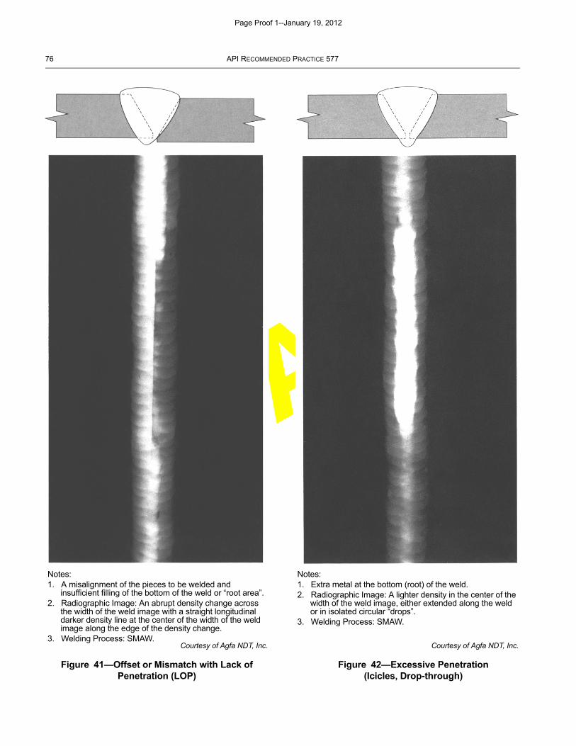
DRAFT
76 API RECOMMENDED PRACTICE 577
Courtesy of Agfa NDT, Inc.
Figure 41—Offset or Mismatch with Lack of Penetration (LOP)
Courtesy of Agfa NDT, Inc.
Figure 42—Excessive Penetration (Icicles, Drop-through)
Notes:1. A misalignment of the pieces to be welded and
insufficient filling of the bottom of the weld or “root area”.2. Radiographic Image: An abrupt density change across
the width of the weld image with a straight longitudinal darker density line at the center of the width of the weld image along the edge of the density change.
3. Welding Process: SMAW.
Notes:1. Extra metal at the bottom (root) of the weld.2. Radiographic Image: A lighter density in the center of the
width of the weld image, either extended along the weld or in isolated circular “drops”.
3. Welding Process: SMAW.
Page Proof 1--January 19, 2012
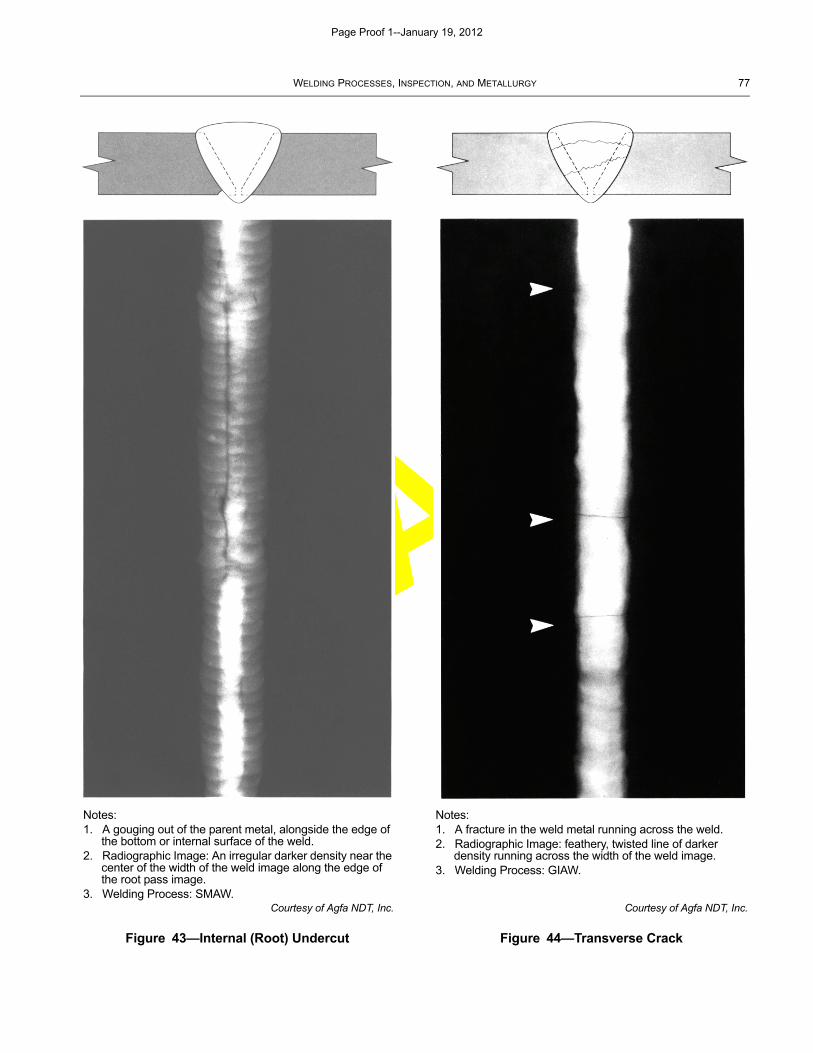
DRAFT
WELDING PROCESSES, INSPECTION, AND METALLURGY 77
Courtesy of Agfa NDT, Inc.
Figure 43—Internal (Root) Undercut
Courtesy of Agfa NDT, Inc.
Figure 44—Transverse Crack
Notes:1. A gouging out of the parent metal, alongside the edge of
the bottom or internal surface of the weld.2. Radiographic Image: An irregular darker density near the
center of the width of the weld image along the edge of the root pass image.
3. Welding Process: SMAW.
Notes:1. A fracture in the weld metal running across the weld.2. Radiographic Image: feathery, twisted line of darker
density running across the width of the weld image.3. Welding Process: GIAW.
Page Proof 1--January 19, 2012
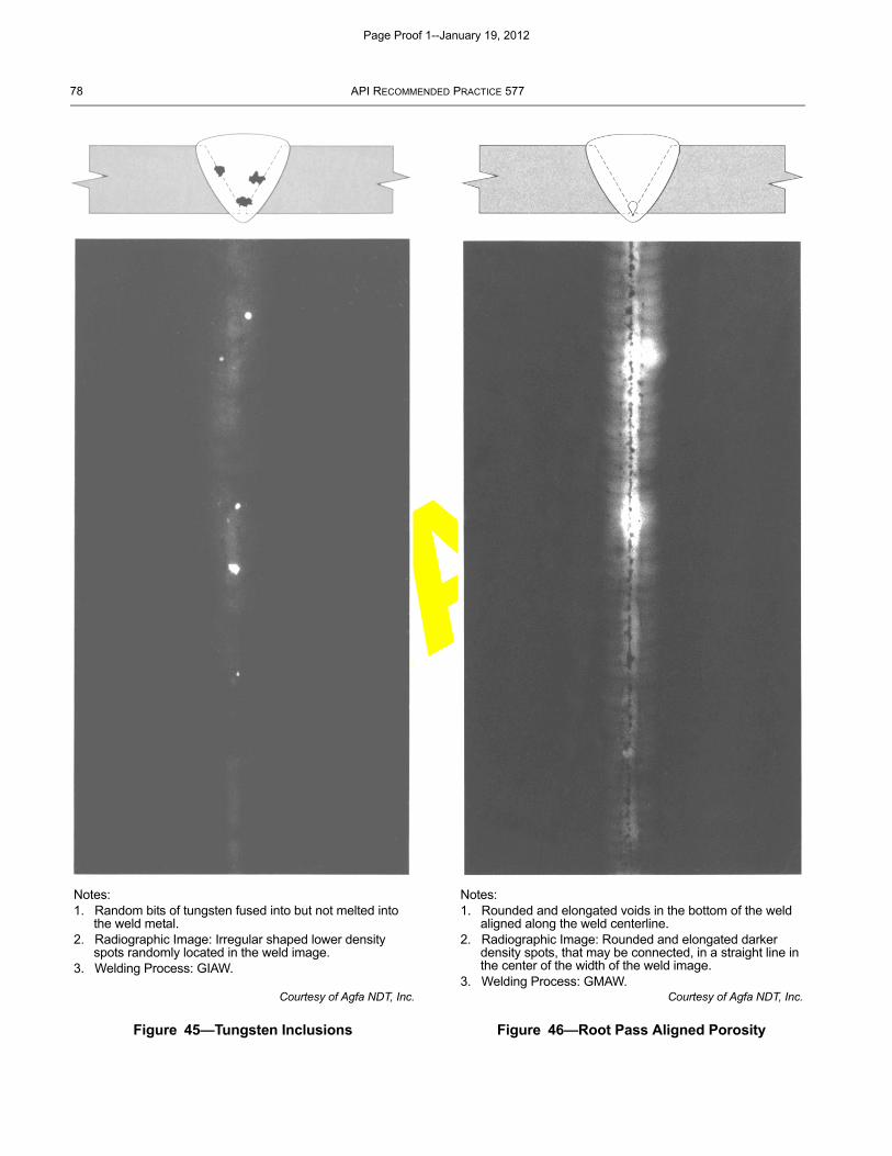
DRAFT
78 API RECOMMENDED PRACTICE 577
Courtesy of Agfa NDT, Inc.
Figure 45—Tungsten Inclusions
Courtesy of Agfa NDT, Inc.
Figure 46—Root Pass Aligned Porosity
Notes:1. Random bits of tungsten fused into but not melted into
the weld metal.2. Radiographic Image: Irregular shaped lower density
spots randomly located in the weld image.3. Welding Process: GIAW.
Notes:1. Rounded and elongated voids in the bottom of the weld
aligned along the weld centerline.2. Radiographic Image: Rounded and elongated darker
density spots, that may be connected, in a straight line in the center of the width of the weld image.
3. Welding Process: GMAW.
Page Proof 1--January 19, 2012
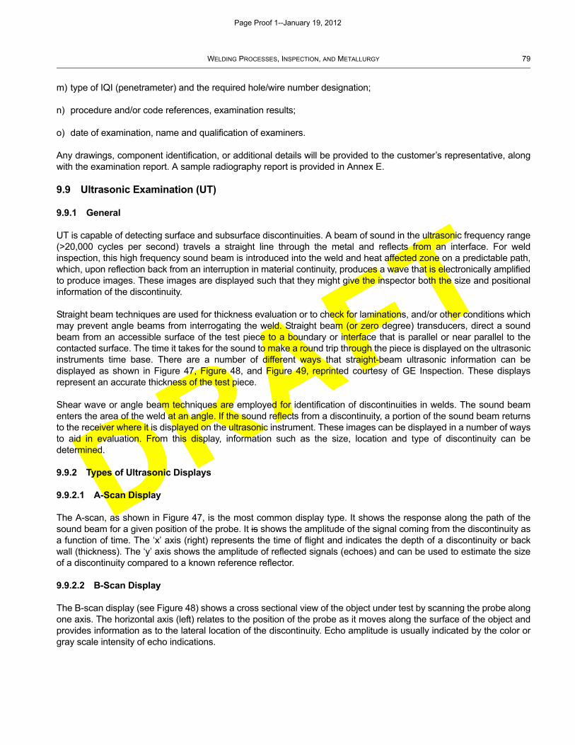
DRAFT
WELDING PROCESSES, INSPECTION, AND METALLURGY 79
m) type of IQI (penetrameter) and the required hole/wire number designation;
n) procedure and/or code references, examination results;
o) date of examination, name and qualification of examiners.
Any drawings, component identification, or additional details will be provided to the customer’s representative, alongwith the examination report. A sample radiography report is provided in Annex E.
9.9 Ultrasonic Examination (UT)
9.9.1 General
UT is capable of detecting surface and subsurface discontinuities. A beam of sound in the ultrasonic frequency range(>20,000 cycles per second) travels a straight line through the metal and reflects from an interface. For weldinspection, this high frequency sound beam is introduced into the weld and heat affected zone on a predictable path,which, upon reflection back from an interruption in material continuity, produces a wave that is electronically amplifiedto produce images. These images are displayed such that they might give the inspector both the size and positionalinformation of the discontinuity.
Straight beam techniques are used for thickness evaluation or to check for laminations, and/or other conditions whichmay prevent angle beams from interrogating the weld. Straight beam (or zero degree) transducers, direct a soundbeam from an accessible surface of the test piece to a boundary or interface that is parallel or near parallel to thecontacted surface. The time it takes for the sound to make a round trip through the piece is displayed on the ultrasonicinstruments time base. There are a number of different ways that straight-beam ultrasonic information can bedisplayed as shown in Figure 47, Figure 48, and Figure 49, reprinted courtesy of GE Inspection. These displaysrepresent an accurate thickness of the test piece.
Shear wave or angle beam techniques are employed for identification of discontinuities in welds. The sound beamenters the area of the weld at an angle. If the sound reflects from a discontinuity, a portion of the sound beam returnsto the receiver where it is displayed on the ultrasonic instrument. These images can be displayed in a number of waysto aid in evaluation. From this display, information such as the size, location and type of discontinuity can bedetermined.
9.9.2 Types of Ultrasonic Displays
9.9.2.1 A-Scan Display
The A-scan, as shown in Figure 47, is the most common display type. It shows the response along the path of thesound beam for a given position of the probe. It is shows the amplitude of the signal coming from the discontinuity asa function of time. The ‘x’ axis (right) represents the time of flight and indicates the depth of a discontinuity or backwall (thickness). The ‘y’ axis shows the amplitude of reflected signals (echoes) and can be used to estimate the sizeof a discontinuity compared to a known reference reflector.
9.9.2.2 B-Scan Display
The B-scan display (see Figure 48) shows a cross sectional view of the object under test by scanning the probe alongone axis. The horizontal axis (left) relates to the position of the probe as it moves along the surface of the object andprovides information as to the lateral location of the discontinuity. Echo amplitude is usually indicated by the color orgray scale intensity of echo indications.
Page Proof 1--January 19, 2012
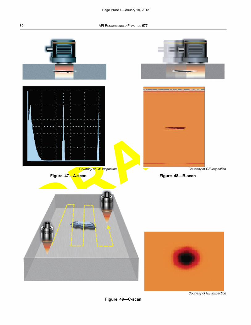
DRAFT
80 API RECOMMENDED PRACTICE 577
Figure 49—C-scan
Courtesy of GE Inspection
Figure 47—A-scan
Courtesy of GE Inspection
Figure 48—B-scan
Courtesy of GE Inspection
Page Proof 1--January 19, 2012
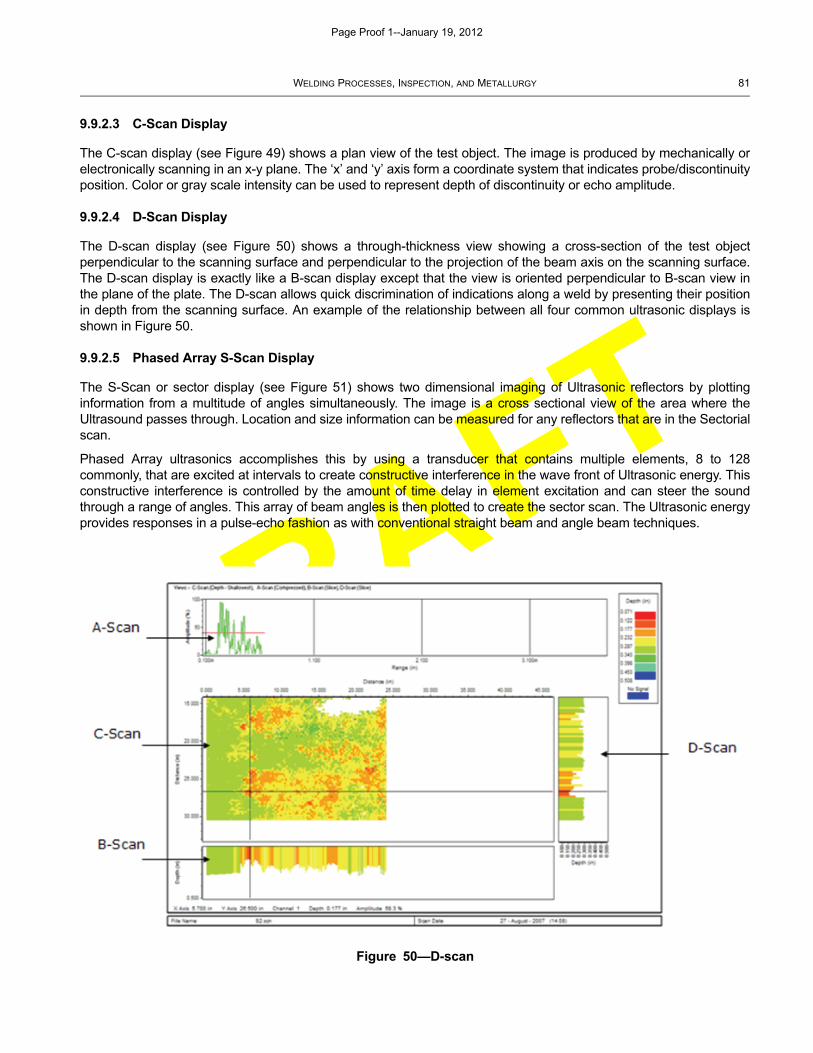
DRAFT
WELDING PROCESSES, INSPECTION, AND METALLURGY 81
9.9.2.3 C-Scan Display
The C-scan display (see Figure 49) shows a plan view of the test object. The image is produced by mechanically orelectronically scanning in an x-y plane. The ‘x’ and ‘y’ axis form a coordinate system that indicates probe/discontinuityposition. Color or gray scale intensity can be used to represent depth of discontinuity or echo amplitude.
9.9.2.4 D-Scan Display
The D-scan display (see Figure 50) shows a through-thickness view showing a cross-section of the test objectperpendicular to the scanning surface and perpendicular to the projection of the beam axis on the scanning surface.The D-scan display is exactly like a B-scan display except that the view is oriented perpendicular to B-scan view inthe plane of the plate. The D-scan allows quick discrimination of indications along a weld by presenting their positionin depth from the scanning surface. An example of the relationship between all four common ultrasonic displays isshown in Figure 50.
9.9.2.5 Phased Array S-Scan Display
The S-Scan or sector display (see Figure 51) shows two dimensional imaging of Ultrasonic reflectors by plottinginformation from a multitude of angles simultaneously. The image is a cross sectional view of the area where theUltrasound passes through. Location and size information can be measured for any reflectors that are in the Sectorialscan.
Phased Array ultrasonics accomplishes this by using a transducer that contains multiple elements, 8 to 128commonly, that are excited at intervals to create constructive interference in the wave front of Ultrasonic energy. Thisconstructive interference is controlled by the amount of time delay in element excitation and can steer the soundthrough a range of angles. This array of beam angles is then plotted to create the sector scan. The Ultrasonic energyprovides responses in a pulse-echo fashion as with conventional straight beam and angle beam techniques.
Figure 50—D-scan
Page Proof 1--January 19, 2012
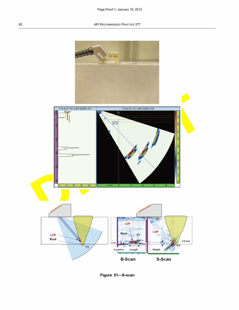
DRAFT
82 API RECOMMENDED PRACTICE 577
Figure 51—S-scan
Page Proof 1--January 19, 2012
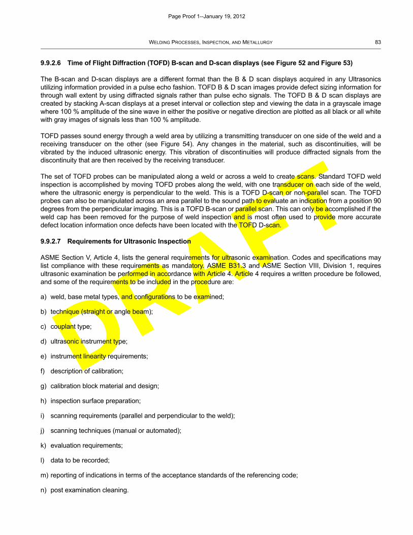
DRAFT
WELDING PROCESSES, INSPECTION, AND METALLURGY 83
9.9.2.6 Time of Flight Diffraction (TOFD) B-scan and D-scan displays (see Figure 52 and Figure 53)
The B-scan and D-scan displays are a different format than the B & D scan displays acquired in any Ultrasonicsutilizing information provided in a pulse echo fashion. TOFD B & D scan images provide defect sizing information forthrough wall extent by using diffracted signals rather than pulse echo signals. The TOFD B & D scan displays arecreated by stacking A-scan displays at a preset interval or collection step and viewing the data in a grayscale imagewhere 100 % amplitude of the sine wave in either the positive or negative direction are plotted as all black or all whitewith gray images of signals less than 100 % amplitude.
TOFD passes sound energy through a weld area by utilizing a transmitting transducer on one side of the weld and areceiving transducer on the other (see Figure 54). Any changes in the material, such as discontinuities, will bevibrated by the induced ultrasonic energy. This vibration of discontinuities will produce diffracted signals from thediscontinuity that are then received by the receiving transducer.
The set of TOFD probes can be manipulated along a weld or across a weld to create scans. Standard TOFD weldinspection is accomplished by moving TOFD probes along the weld, with one transducer on each side of the weld,where the ultrasonic energy is perpendicular to the weld. This is a TOFD D-scan or non-parallel scan. The TOFDprobes can also be manipulated across an area parallel to the sound path to evaluate an indication from a position 90degrees from the perpendicular imaging. This is a TOFD B-scan or parallel scan. This can only be accomplished if theweld cap has been removed for the purpose of weld inspection and is most often used to provide more accuratedefect location information once defects have been located with the TOFD D-scan.
9.9.2.7 Requirements for Ultrasonic Inspection
ASME Section V, Article 4, lists the general requirements for ultrasonic examination. Codes and specifications maylist compliance with these requirements as mandatory. ASME B31.3 and ASME Section VIII, Division 1, requiresultrasonic examination be performed in accordance with Article 4. Article 4 requires a written procedure be followed,and some of the requirements to be included in the procedure are:
a) weld, base metal types, and configurations to be examined;
b) technique (straight or angle beam);
c) couplant type;
d) ultrasonic instrument type;
e) instrument linearity requirements;
f) description of calibration;
g) calibration block material and design;
h) inspection surface preparation;
i) scanning requirements (parallel and perpendicular to the weld);
j) scanning techniques (manual or automated);
k) evaluation requirements;
l) data to be recorded;
m) reporting of indications in terms of the acceptance standards of the referencing code;
n) post examination cleaning.
Page Proof 1--January 19, 2012
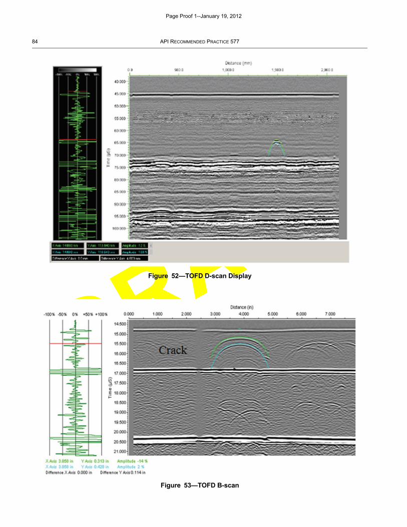
DRAFT
84 API RECOMMENDED PRACTICE 577
Figure 52—TOFD D-scan Display
Figure 53—TOFD B-scan
Page Proof 1--January 19, 2012
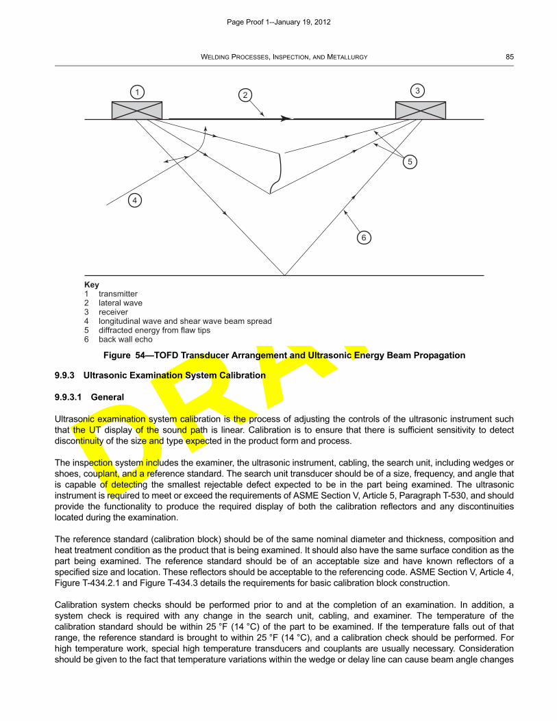
DRAFT
WELDING PROCESSES, INSPECTION, AND METALLURGY 85
9.9.3 Ultrasonic Examination System Calibration
9.9.3.1 General
Ultrasonic examination system calibration is the process of adjusting the controls of the ultrasonic instrument suchthat the UT display of the sound path is linear. Calibration is to ensure that there is sufficient sensitivity to detectdiscontinuity of the size and type expected in the product form and process.
The inspection system includes the examiner, the ultrasonic instrument, cabling, the search unit, including wedges orshoes, couplant, and a reference standard. The search unit transducer should be of a size, frequency, and angle thatis capable of detecting the smallest rejectable defect expected to be in the part being examined. The ultrasonicinstrument is required to meet or exceed the requirements of ASME Section V, Article 5, Paragraph T-530, and shouldprovide the functionality to produce the required display of both the calibration reflectors and any discontinuitieslocated during the examination.
The reference standard (calibration block) should be of the same nominal diameter and thickness, composition andheat treatment condition as the product that is being examined. It should also have the same surface condition as thepart being examined. The reference standard should be of an acceptable size and have known reflectors of aspecified size and location. These reflectors should be acceptable to the referencing code. ASME Section V, Article 4,Figure T-434.2.1 and Figure T-434.3 details the requirements for basic calibration block construction.
Calibration system checks should be performed prior to and at the completion of an examination. In addition, asystem check is required with any change in the search unit, cabling, and examiner. The temperature of thecalibration standard should be within 25 °F (14 °C) of the part to be examined. If the temperature falls out of thatrange, the reference standard is brought to within 25 °F (14 °C), and a calibration check should be performed. Forhigh temperature work, special high temperature transducers and couplants are usually necessary. Considerationshould be given to the fact that temperature variations within the wedge or delay line can cause beam angle changes
Figure 54—TOFD Transducer Arrangement and Ultrasonic Energy Beam Propagation
Key1 transmitter2 lateral wave3 receiver4 longitudinal wave and shear wave beam spread5 diffracted energy from flaw tips6 back wall echo
1 2 3
5
6
4
Page Proof 1--January 19, 2012
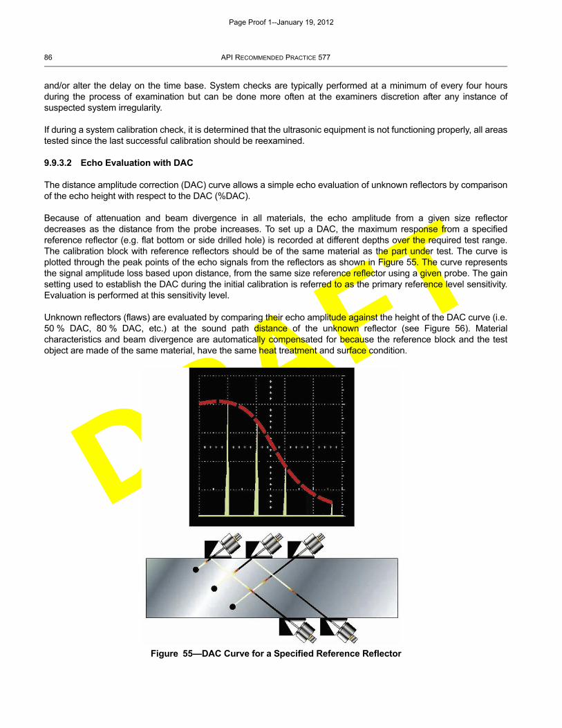
DRAFT
86 API RECOMMENDED PRACTICE 577
and/or alter the delay on the time base. System checks are typically performed at a minimum of every four hoursduring the process of examination but can be done more often at the examiners discretion after any instance ofsuspected system irregularity.
If during a system calibration check, it is determined that the ultrasonic equipment is not functioning properly, all areastested since the last successful calibration should be reexamined.
9.9.3.2 Echo Evaluation with DAC
The distance amplitude correction (DAC) curve allows a simple echo evaluation of unknown reflectors by comparisonof the echo height with respect to the DAC (%DAC).
Because of attenuation and beam divergence in all materials, the echo amplitude from a given size reflectordecreases as the distance from the probe increases. To set up a DAC, the maximum response from a specifiedreference reflector (e.g. flat bottom or side drilled hole) is recorded at different depths over the required test range.The calibration block with reference reflectors should be of the same material as the part under test. The curve isplotted through the peak points of the echo signals from the reflectors as shown in Figure 55. The curve representsthe signal amplitude loss based upon distance, from the same size reference reflector using a given probe. The gainsetting used to establish the DAC during the initial calibration is referred to as the primary reference level sensitivity.Evaluation is performed at this sensitivity level.
Unknown reflectors (flaws) are evaluated by comparing their echo amplitude against the height of the DAC curve (i.e.50 % DAC, 80 % DAC, etc.) at the sound path distance of the unknown reflector (see Figure 56). Materialcharacteristics and beam divergence are automatically compensated for because the reference block and the testobject are made of the same material, have the same heat treatment and surface condition.
Figure 55—DAC Curve for a Specified Reference Reflector
Page Proof 1--January 19, 2012
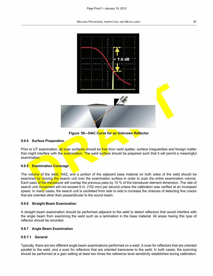
DRAFT
WELDING PROCESSES, INSPECTION, AND METALLURGY 87
9.9.4 Surface Preparation
Prior to UT examination, all scan surfaces should be free from weld spatter, surface irregularities and foreign matterthat might interfere with the examination. The weld surface should be prepared such that it will permit a meaningfulexamination.
9.9.5 Examination Coverage
The volume of the weld, HAZ, and a portion of the adjacent base material on both sides of the weld should beexamined by moving the search unit over the examination surface in order to scan the entire examination volume.Each pass of the transducer will overlap the previous pass by 10 % of the transducer element dimension. The rate ofsearch unit movement will not exceed 6 in. (152 mm) per second unless the calibration was verified at an increasedspeed. In many cases, the search unit is oscillated from side to side to increase the chances of detecting fine cracksthat are oriented other than perpendicular to the sound beam.
9.9.6 Straight Beam Examination
A straight beam examination should be performed adjacent to the weld to detect reflectors that would interfere withthe angle beam from examining the weld such as a lamination in the base material. All areas having this type ofreflector should be recorded.
9.9.7 Angle Beam Examination
9.9.7.1 General
Typically, there are two different angle beam examinations performed on a weld. A scan for reflectors that are orientedparallel to the weld, and a scan for reflectors that are oriented transverse to the weld. In both cases, the scanningshould be performed at a gain setting at least two times the reference level sensitivity established during calibration.
Figure 56—DAC Curve for an Unknown Reflector
Page Proof 1--January 19, 2012
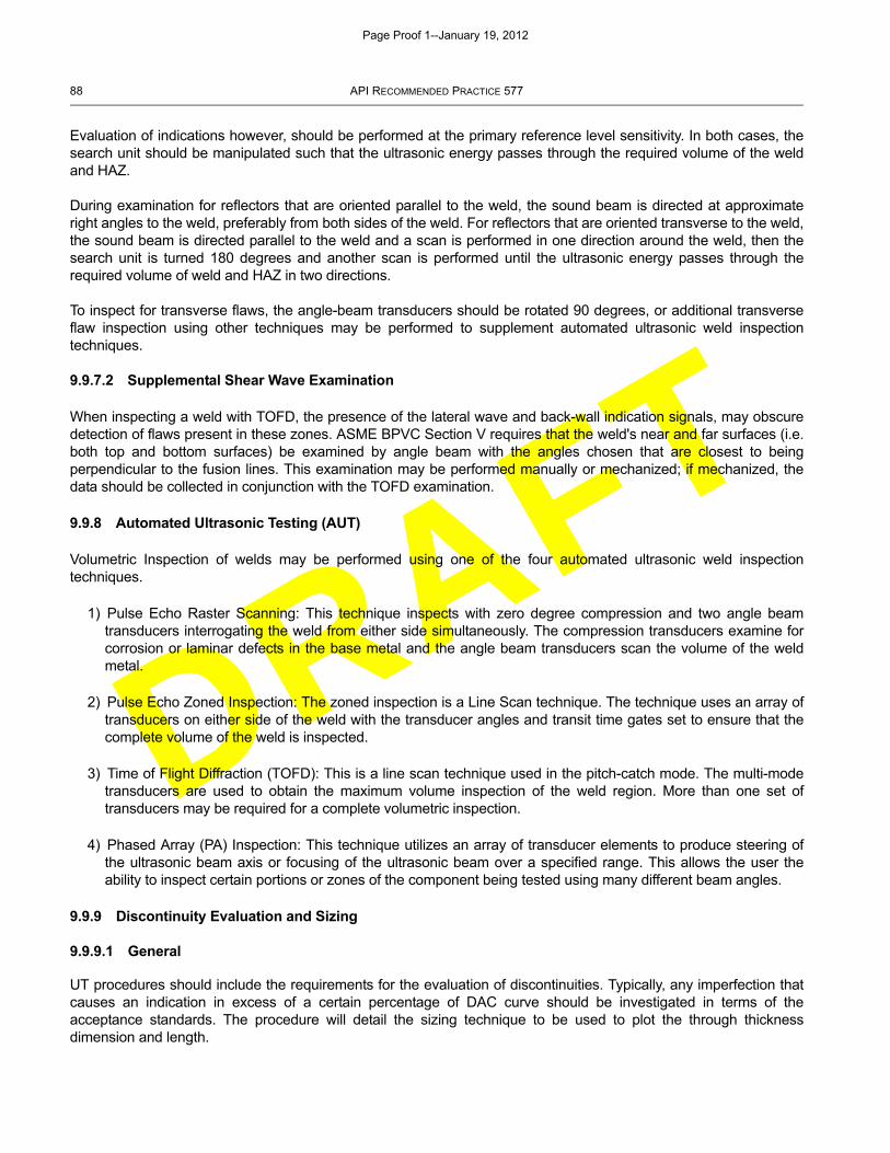
DRAFT
88 API RECOMMENDED PRACTICE 577
Evaluation of indications however, should be performed at the primary reference level sensitivity. In both cases, thesearch unit should be manipulated such that the ultrasonic energy passes through the required volume of the weldand HAZ.
During examination for reflectors that are oriented parallel to the weld, the sound beam is directed at approximateright angles to the weld, preferably from both sides of the weld. For reflectors that are oriented transverse to the weld,the sound beam is directed parallel to the weld and a scan is performed in one direction around the weld, then thesearch unit is turned 180 degrees and another scan is performed until the ultrasonic energy passes through therequired volume of weld and HAZ in two directions.
To inspect for transverse flaws, the angle-beam transducers should be rotated 90 degrees, or additional transverseflaw inspection using other techniques may be performed to supplement automated ultrasonic weld inspectiontechniques.
9.9.7.2 Supplemental Shear Wave Examination
When inspecting a weld with TOFD, the presence of the lateral wave and back-wall indication signals, may obscuredetection of flaws present in these zones. ASME BPVC Section V requires that the weld's near and far surfaces (i.e.both top and bottom surfaces) be examined by angle beam with the angles chosen that are closest to beingperpendicular to the fusion lines. This examination may be performed manually or mechanized; if mechanized, thedata should be collected in conjunction with the TOFD examination.
9.9.8 Automated Ultrasonic Testing (AUT)
Volumetric Inspection of welds may be performed using one of the four automated ultrasonic weld inspectiontechniques.
1) Pulse Echo Raster Scanning: This technique inspects with zero degree compression and two angle beamtransducers interrogating the weld from either side simultaneously. The compression transducers examine forcorrosion or laminar defects in the base metal and the angle beam transducers scan the volume of the weldmetal.
2) Pulse Echo Zoned Inspection: The zoned inspection is a Line Scan technique. The technique uses an array oftransducers on either side of the weld with the transducer angles and transit time gates set to ensure that thecomplete volume of the weld is inspected.
3) Time of Flight Diffraction (TOFD): This is a line scan technique used in the pitch-catch mode. The multi-modetransducers are used to obtain the maximum volume inspection of the weld region. More than one set oftransducers may be required for a complete volumetric inspection.
4) Phased Array (PA) Inspection: This technique utilizes an array of transducer elements to produce steering ofthe ultrasonic beam axis or focusing of the ultrasonic beam over a specified range. This allows the user theability to inspect certain portions or zones of the component being tested using many different beam angles.
9.9.9 Discontinuity Evaluation and Sizing
9.9.9.1 General
UT procedures should include the requirements for the evaluation of discontinuities. Typically, any imperfection thatcauses an indication in excess of a certain percentage of DAC curve should be investigated in terms of theacceptance standards. The procedure will detail the sizing technique to be used to plot the through thicknessdimension and length.
Page Proof 1--January 19, 2012
DRAFT
WELDING PROCESSES, INSPECTION, AND METALLURGY 89
One commonly used sizing technique is called the “intensity drop” or “6 dB drop” technique. This sizing techniqueuses the beam spread of the transducer to quickly estimate the axial length of the reflector. Using this technique, thetransducer is positioned on the part such that the amplitude from the reflector is maximized. This point is marked witha grease pencil. The UT instrument is adjusted to set the signal to 80 % full screen height (FSH). The transducer isthen moved laterally until the echo has dropped to 40 % FSH (6dB). This position is also marked. The transducer isthen moved laterally in the other direction, past the maximum amplitude point, until the echo response again reaches40 % FSH. This point is marked with the grease pencil. The two outside marks will provide the approximate axial sizeof the flaw.
Other sizing techniques should be used to get a more precise measurement of the length and through wall dimensionof the flaw. With advances in technologies a number of other through-thickness sizing techniques are described in9.9.9.2, 9.9.9.3, 9.9.9.4, and 9.9.9.5.
9.9.9.2 The ID Creeping Wave Method
The ID Creeping wave method uses the effects of multiple sound modes, such as longitudinal waves and shearwaves to qualitatively size flaws. The method is used for the global location of flaws in the bottom 1/3, middle 1/3, andtop 1/3 regions. Three specific waves are presented with the ID Creeping wave method.
a) High angle refracted longitudinal wave of approximately 70 degrees.
b) Direct 30 degree shear wave which mode converts to a 70 degree refracted longitudinal wave.
c) Indirect shear or “head” wave which mode converts at the inside diameter from a shear wave to a longitudinalwave, and moves along the surface.
9.9.9.3 The Tip Diffraction Method
Tip diffraction methods are very effective for sizing flaws which are open to the inside or outside diameter surface. ForID connected flaws, the half “V” path or one and one half “V” path technique is used. For OD connected flaws, twotechniques are available; the time-of-flight tip diffraction technique and the time measurement technique of the tipdiffracted signal and the base signal.
9.9.9.4 The High Angle Longitudinal Method
The high angle refracted longitudinal wave method is very effective for very deep flaws. Dual element, focused, 60,70, and OD creeping wave are used to examine the outer one half thickness of the component material. Probedesigns vary with the manufacturer. Depth of penetration is dependent upon angle of refraction, frequency, andfocused depth. Many of these transducers are used not only for sizing, but also for detection and confirmation of flawsdetected during the primary detection examination. For coarse grain materials, these probes work well where shearwave probes are ineffective.
9.9.9.5 The Bimodal Method
The bimodal method is a dual element tandem probe with the transducers crystals located one in front of the other.The probe also generates an ID creeping wave. The wave physics are essentially the same. The pseudo-focusingeffect of the dual element crystals is very effective for ID connected flaws in the mid-wall region, 30 % to 60 % throughwall depth. A low angle shear wave (indirect) mode converts at the ID to produce an ID creeping wave, which detectsthe base of the flaw. A further low angle shear wave mode converts at the ID to a longitudinal wave, which reflects alongitudinal wave from the flaw face. A high angle refracted longitudinal wave detects the upper extremity of the flaw(70 degrees). The bimodal method can be used to confirm the depth of shallow to deep ID connected flaws. However,very shallow flaws of less than 10 % to 20 % tend to be slightly oversized, and very deep flaws tend to be slightlyundersized.
Page Proof 1--January 19, 2012
DRAFT
90 API RECOMMENDED PRACTICE 577
Significant training and experience is required to effectively utilize some of the more advanced UT detection andsizing techniques.
9.9.9.6 The Phased Array Method
The phased array method utilizes an array of transducer elements, excited in precise timing patterns, to produce steeror focus the ultrasonic beam over a specific range of angles in the component being inspected. The system consistsof a computerized ultrasonic pulser/receiver instrument that contains the collection setup and analysis software, anumbilical cable, and the phased array probe/wedge. The phased inspection may be performed manually, or with anencoder for semi-automated scans, or with a mechanized scanner for fully automated scanning.
The method allows the user the ability to inspect certain portions or zones of the component being tested using manydifferent beam angles. The results may be viewed as A-scan, B-scan, C-scan, or as a Sectorial scan images. Multipleviews may be viewed simultaneously as well for assistance with data analysis. This technique is also used in a singleaxis scan motion which makes it more efficient than manual scanning for data collection.
9.10 Hardness Testing
9.10.1 Hardness Testing for PQR and Production Welds
Hardness testing of the weld and HAZ is often required to assure the welding process and any PWHT resulted in anacceptably “soft” result. Testing production welds and HAZ requires test areas to be ground flat or even flush with thebase metal to accommodate the hardness testing instrument in the area of interest. The HAZ can be difficult to locateand is often assumed for testing purposes to be just adjacent to the toe of the weld. Testing coupons for a PQR iseasier for the coupon is cross-sectioned and etched to identify the weld, fusion line and HAZ. API RecommendedPractice 582 details hardness test requirements for PQRs and production welds. High hardness is particularly anissue with hardenable materials where the weld size is small compared to the base metal being welded (i.e. tube-to-tubesheet welds).
Hardness testing of production welds often utilizes portable equipment. Field measurements tend to have greatervariability and so additional measurements may be required to verify results. However, hardness testing performed aspart of the PQR will use laboratory equipment where greater accuracy is possible. Portable hardness testers are notsubstitutes for the bench top models, and results from portable testers should be given careful review.
9.10.2 Hardness Testing for Repair Welds
On site hardness testing may be required on pressure retaining welds after any PWHT in accordance with API 582and NACE SP 0472. Hardness testing of repair welds can be conducted with portable hardness testers in accordancewith either ASTM A833, ASTM A1038, or ASTM A956
Using API 582 as reference, the HAZ reading may include location as close as possible (approximately 0.2 mm) tothe weld fusion (see Figure 57). The surface should be polished and should not exceed 16 μin. (0.4 μm) maximum.After the surface has been polished, it should be etched to identify the weld metal, fusion line and HAZ.
Hardness measurements may be conducted at locations shown in Figure 57. Five impressions in an area ofapproximately 1 in.2 (645 mm2) should constitute a test. Because field hardness measurements tend to have greatervariability, additional assessment such as “Field Metallography Replication” (FMR) can be conducted to determinewhether an excessively hard HAZ microstructure has been formed.
9.11 Pressure and Leak Testing (LT)
Where a hydrostatic or pneumatic pressure test is required by code, the inspector should adopt code andspecification requirements relevant to vessels or piping. API 510, API 570, API 574, and ASME B31.3 provideguidance on the application of pressure tests. Pressure tests should be conducted at temperatures appropriate for thematerial of construction to avoid brittle fracture.
Page Proof 1--January 19, 2012
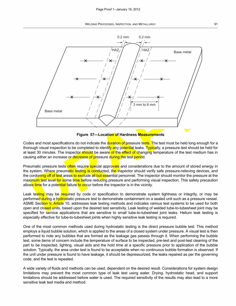
DRAFT
WELDING PROCESSES, INSPECTION, AND METALLURGY 91
Codes and most specifications do not indicate the duration of pressure tests. The test must be held long enough for athorough visual inspection to be completed to identify any potential leaks. Typically, a pressure test should be held forat least 30 minutes. The inspector should be aware of the effect of changing temperature of the test medium has incausing either an increase or decrease of pressure during the test period.
Pneumatic pressure tests often require special approvals and considerations due to the amount of stored energy inthe system. Where pneumatic testing is conducted, the inspector should verify safe pressure-relieving devices, andthe cordoning off of test areas to exclude all but essential personnel. The inspector should monitor the pressure at themaximum test level for some time before reducing pressure and performing visual inspection. This safety precautionallows time for a potential failure to occur before the inspector is in the vicinity.
Leak testing may be required by code or specification to demonstrate system tightness or integrity, or may beperformed during a hydrostatic pressure test to demonstrate containment on a sealed unit such as a pressure vessel.ASME Section V, Article 10, addresses leak testing methods and indicates various test systems to be used for bothopen and closed units, based upon the desired test sensitivity. Leak testing of welded tube-to-tubesheet joint may bespecified for service applications that are sensitive to small tube-to-tubesheet joint leaks. Helium leak testing isespecially effective for tube-to-tubesheet joints when highly sensitive leak testing is required.
One of the most common methods used during hydrostatic testing is the direct pressure bubble test. This methodemploys a liquid bubble solution, which is applied to the areas of a closed system under pressure. A visual test is thenperformed to note any bubbles that are formed as the leakage gas passes through it. When performing the bubbletest, some items of concern include the temperature of surface to be inspected, pre-test and post-test cleaning of thepart to be inspected, lighting, visual aids and the hold time at a specific pressure prior to application of the bubblesolution. Typically, the area under test is found to be acceptable when no continuous bubble formation is observed. Ifthe unit under pressure is found to have leakage, it should be depressurized, the leaks repaired as per the governingcode, and the test is repeated.
A wide variety of fluids and methods can be used, dependent on the desired result. Considerations for system designlimitations may prevent the most common type of leak test using water. Drying, hydrostatic head, and supportlimitations should be addressed before water is used. The required sensitivity of the results may also lead to a moresensitive leak test media and method.
Figure 57—Location of Hardness Measurements
0.2 mm 0.2 mm
HAZ HAZ Base metal
Base metal
3 mm to 6 mm
Page Proof 1--January 19, 2012
DRAFT
92 API RECOMMENDED PRACTICE 577
9.12 Weld Inspection Data Recording
9.12.1 Reporting Details
Results of the weld inspection should be completely and accurately documented. The inspection report, in manycases will become a permanent record to be maintained and referenced for the life of the weld or part beinginspected. Information that might be included in an inspection report is listed in 9.12.1.1, 9.12.1.2, and 9.12.1.3.
9.12.1.1 General Information
[needs lead-in paragraph]
a) Customer or project.
b) Contract number or site.
c) Date of inspection.
d) Component/system.
e) Subassembly/description.
f) Weld identification.
g) Weld type/material/thickness.
9.12.1.2 Inspection Information
[needs lead-in paragraph]
a) Date of inspection.
b) Procedure number.
c) Examiner.
d) Examiner certification information.
e) Inspection method.
f) Visual aids and other equipment used.
g) Weld reference datum point.
9.12.1.3 Inspection Results
[needs lead-in paragraph]
a) Inspection sheet number.
b) Inspection limitations.
c) Inspection results.
Page Proof 1--January 19, 2012

DRAFT
WELDING PROCESSES, INSPECTION, AND METALLURGY 93
d) A description of all recordable and reportable indications.
e) For each recordable indication:
1) indication number;
2) location of indication (from both weld reference datum and centerline);
3) upstream or downstream (clockwise or counterclockwise) from an established reference point;
4) size and orientation of indication;
5) type of indication (linear or rounded);
6) acceptable per the acceptance standards of the referencing code;
7) remarks or notes;
8) include a sketch of indication;
9) reviewer and level of certification;
10) reviewers comments.
9.12.2 Terminology
When reporting the results of an inspection it is important to use standard terminology. Examples of standardterminology are shown in Table 8, Table 9, and Table 10.
Table 8—Conditions that May Exist in a Material or Product
Definition Description or Comment
A-1 Indication: A condition of being imperfect; a departure of a quality characteristic from its intended condition.
No inherent or implied association with lack of conformance with specification requirements or with lack of fitness for purpose, i.e. indication may or may not be rejectable.
A-2 Discontinuity: An interruption of the typical structure of a material, such as a lack of homogeneity in its mechanical, metallurgical, or physical characteristics. A discontinuity is not necessarily a defect.
No inherent or applied association with lack of conformance with specification requirements or with lack of fitness for purpose, i.e. imperfection may or may not be rejectable.
An unintentional discontinuity is also an imperfection. Cracks, inclusions and porosity are examples of unintentional discontinuities that are also imperfections.
Intentional discontinuities may be present in some material or products because of intentional changes in configuration; these are not imperfections and are not expected to be evaluated as such.
Table 9—Results of Non-destructive Examination
Definition Description or Comment
B-1 Indication: The response or evidence from the application of a non-destructive examination.
When the nature or magnitude of the indication suggests that the cause is an imperfection or discontinuity, evaluation is required.
Page Proof 1--January 19, 2012
DRAFT
94 API RECOMMENDED PRACTICE 577
10 Metallurgy
10.1 General
Metallurgy is a complex science but a general understanding of the major principles is important to the inspector, dueto the wide variety of base metals that may be joined by welding during the repair of equipment, and the significantimpact on the metals resulting from the welding process. The welding process can affect both the mechanicalproperties and the corrosion resistance properties of the weldment. This section is designed to provide an awarenessof metallurgical effects important to personnel performing inspections, but is not to be considered an in depthresource of metallurgy.
Based on the concept that this section provides a basic understanding, this section does not describe all aspects ofmetallurgy such as crystalline structures of materials and atomic configurations, which are left to other more completemetallurgy texts.
10.2 The Structure of Metals and Alloys
10.2.1 General
Solid metals are crystalline in nature and all have a structure in which the atoms of each crystal are arranged in aspecific geometric pattern. The physical properties of metallic materials including strength, ductility and toughnesscan be attributed to the chemical make-up and orderly arrangement of these atoms.
Metals in molten or liquid states have no orderly arrangement to the atoms contained in the melt. As the melt cools, atemperature is reached at which clusters of atoms bond with each other and start to solidify developing into solidcrystals within the melt. The individual crystals of pure metal are identical except for their orientation and are calledgrains. As the temperature is reduced further, these crystals change in form eventually touch and where the grainstouch an irregular transition layer of atoms is formed, which is called the grain boundary. Eventually the entire meltsolidifies, interlocking the grains into a solid metallic structure called a casting.
Knowledge of cast structures is important since the welding process is somewhat akin to making a casting in afoundry. Because of the similarity in the shape of its grains, a weld can be considered a small casting. A solidifiedweld may have a structure that looks very much like that of a cast piece of equipment. However, the thermalconditions that are experienced during welding produce a cast structure with characteristics unique to welding.
Table 10—Results of Application of Acceptance/Rejection Criteria
Definition Description or Comment
C-1 Flaw: An imperfection or unintentional discontinuity, which is detectable by a non-destructive examination.
No inherent or implied association with lack of conformance with specification requirements or lack of fitness for purpose, i.e. a flaw may or may not be rejectable.
C-2 Defect: A flaw (imperfection or unintentional discontinuity) of such size, shape, orientation, location or property, which is rejectable.
Always rejectable, either for:
a) Lack of conformance to specification requirements.
b) Potential lack of fitness for purpose
c) Both
A defect (a rejectable flaw) is by definition a condition, which must be removed or corrected.
Page Proof 1--January 19, 2012
DRAFT
WELDING PROCESSES, INSPECTION, AND METALLURGY 95
10.2.2 Castings
The overall arrangement of the grains, grain boundaries and phases present in the casting is called themicrostructure of the metal. Microstructure is a significant area that inspectors should understand, as it is largelyresponsible for the physical and mechanical properties of the metal. Because castings used in the refinery industryare typically alloyed, they will contain two or more microstructural phases. A phase is any structure that is physicallyand compositionally distinct. As the chemical composition is altered or temperature changed, new phases may formor existing phases may disappear.
Cast structures, depending on their chemical composition can exhibit a wide range of mechanical properties forseveral reasons. In general, it is desirable to keep the size of grains small, which improves strength and toughness.This can be achieved by maximizing the rate of cooling or minimizing the heat input (in the case of welding). Thisincreases the rate of crystal formation and decreases the time available for crystal growth, which has a net effect ofreducing crystalline grain size.
The properties of the cast structure can also be impaired by compositional variations in the microstructure calledsegregation. Because of the solubility of trace and alloying elements, such elements as carbon, sulfur, andphosphorous, can vary in a pure metal, these elements can cause variations in the solidification temperature ofdifferent microstructural phases within the melt. As the melt cools, these elements are eventually contained in themicro structural phases that solidify last in spaces between the grains. These grain boundary regions can have amuch higher percentage of trace elements that the grains themselves, which may lead to reductions in ductility andstrength properties. This effect can be minimized by using high purity melting stocks, by special melting practices(melting under vacuum or inert gas, for example) to minimize contamination and/or subsequent heat treatment tohomogenize the structure. In many carbon steels this is achieved using oxygen scavengers such as aluminum,silicon, or silicon plus aluminum and the steels are often described as “killed” or “fully killed” steels. Minimizing traceelements or “inclusions” at this stage is often important as they can provide sites for formation of in-service defectssuch as hydrogen assisted cracking.
Gases, such as hydrogen, which become entrapped in the melt as it solidifies, can also affect casting integrity. Insome cases, these create voids or porosity in the structure, or can lead to cracking. Weldments are particularly proneto cracking because of trapped hydrogen gases. This problem can be avoided by careful cleaning of the weld bevelsto remove hydrocarbons and moisture, the use of low-hydrogen electrodes, correct storage or baking of electrodesand use of proper purging techniques with high quality welding gases.
For refinery applications, castings are used primarily for components having complex shapes in order to minimize theamount of machining required. These include pump components (casings, impellers, and stuffing boxes) and valvebodies.
10.2.3 Wrought Materials
The vast majority of metallic materials used for the fabrication of refinery and chemical plant equipment are used inthe wrought form rather than cast. Mechanical working of the cast ingot produces wrought materials by processessuch as rolling, forging, or extrusion, which are normally performed at an elevated temperature. These processesresult in a microstructure that has a uniform composition, and a smaller, more uniform grain shape.
Wrought materials may consist of one or more microstructural phases that may have different grain structures.Austenitic stainless steels, for example, are composed of microstructural phase call austenite, which has grains of thesame crystal structure. Many nickel, aluminum, titanium, and copper alloys are also single-phase materials. Single-phase materials are often strengthened by the addition of alloying elements that lead to the formation of nonmetallicor intermetallic precipitates. The addition of carbon to austenitic stainless steels, for example, leads to the formation ofvery small iron and chromium carbide precipitates in the grains and at grain boundaries. The effect of theseprecipitates is to strengthen the alloy. However, the formation of chromium carbide precipitates on the grainboundaries during welding (or other high temperature exposure) depletes the area adjacent to the grain boundaries ofchromium. This microstructure in austenitic stainless steel is referred to as a “sensitized microstructure”. As a result,
Page Proof 1--January 19, 2012
DRAFT
96 API RECOMMENDED PRACTICE 577
the chromium-depleted area adjacent to the grain boundary may experience severe intergranular corrosion. Ingeneral, greater strengthening occurs with the finer distribution of precipitates. This effect is usually dependent ontemperature; at elevated temperatures, the precipitates begin to breakdown and the strengthening effect is lost.
Alloys may also consist of more than one microstructural phase and crystal structure. A number of copper alloysincluding some brasses are composed of two distinct phases. Plain carbon steel is also a two-phase alloy. One phaseis a relatively pure form of iron called ferrite. By itself, ferrite is a fairly weak material. With the addition of more than0.06 % carbon, a second phase called pearlite is formed which adds strength to steel. Pearlite is a lamellar (i.e. plate-like) mixture of ferrite and Fe3C iron carbide.
As a result of fast cooling such as quenching in non-alloyed steels and also with the addition of alloying elementssuch as chromium to steel, other phases may form. Rather than pearlite, phases such as bainite or martensite maybe produced. These phases tend to increase the strength and hardness of the metal with some loss of ductility. Theformation of structures such as bainite and martensite may also be the result of rapid or controlled cooling andreheating within certain temperature ranges often termed “quenching” and “tempering.”
10.2.4 Welding Metallurgy
Welding metallurgy is concerned with melting, solidification, gas-metal reactions, slag-metal reactions, surfacephenomena and base metal reactions. These reactions occur very rapidly during welding due to the rapid changes intemperature caused by the welding process. This is in contrast to metallurgy of castings, which tends to be slowerand often more controlled. There are three parts of a weld: the weld metal, heat-affected metal (zone), and basemetal. The metallurgy of each area is related to the composition of the base and weld metal, the welding process andwelding procedures used.
Most typical weld metals are rapidly solidified and, like the structure of a casting described earlier, usually solidify inthe same manner as a casting and have a fine grain dendritic microstructure. The solidified weld metal is a mixture ofmelted base metal and deposited weld filler metal, if used. In most welds, there will also be segregation of alloyelements. The amount of segregation is determined by the chemical composition of the weld and the base metal.Consequently, the weld will be less homogenous than the base metal, which can affect the mechanical properties ofthe weld.
The heat-affected zone (HAZ) is adjacent to the weld and is that portion of the base metal that has not been melted,but whose mechanical properties or microstructure have been altered by the preheating temperature and the heat ofwelding. There will typically be a change in grain size or grain structure and hardness in the HAZ of steel. The size orwidth of the HAZ is dependent on the heat input used during welding. For carbon steels, the HAZ includes thoseregions heated to greater than 1350 °F (700 °C). Each weld pass applied will have its own HAZ and the overlappingheat affected zones will extend through the full thickness of the plate or part welded.
The third component in a welded joint is the base metal. Most of the common carbon and low-alloy steels used fortanks and pressure vessels are weldable. The primary factor affecting the weldability of a base metal is its chemicalcomposition. Each type of metal has welding procedural limits within which sound welds with satisfactory propertiescan be made. If these limits are wide, the metal is said to have good weldability. Conversely, if the limits are narrow,the metal is said to have poor weldability.
An important aspect of welding metallurgy is the gas metal reaction between the molten weld metal and gasespresent during welding. Gas metal reactions depend on the presence of oxygen, hydrogen, or nitrogen, individually orcombined in the shielding atmosphere. Oxygen can be drawn in from the atmosphere or occur from the dissociationof water vapor, carbon dioxide, or metal oxide. Air is the most common source of nitrogen, but it can also be used ashielding gas for welding of austenitic or duplex stainless steels. There are many sources of hydrogen. In SMAW orSAW, hydrogen may be present as water in the electrode coating or loose flux. Hydrogen can also come fromlubricants, water on the work piece, surface oxides, or humidity or rain.
Page Proof 1--January 19, 2012
DRAFT
WELDING PROCESSES, INSPECTION, AND METALLURGY 97
An important factor in selecting shielding gases is the type or mixture. A reactive gas such as carbon dioxide canbreak down at arc temperatures into carbon and oxygen. This is not a problem on carbon and low-alloy steels.However, on high-alloy and reactive metals, this can cause an increase in carbon content and the formation of oxidesthat can lower the corrosion resistant properties of the weld. High-alloy materials welded with gas-shielded processesusually employ inert shielding gases or mixtures with only slight additions of reactive gases to promote arc stability.
10.3 Physical Properties
10.3.1 General
The physical properties of base metals, filler metals and alloys being joined can have an influence on the efficiencyand applicability of a welding process. The nature and properties of gas shielding provided by the decomposition offluxing materials or the direct introduction of shielding gases used to protect the weldment from atmosphericcontamination can have a pronounced effect on its ability to provide adequate shielding and on the final chemical andmechanical properties of a weldment.
The physical properties of a metal or alloy are those, which are relatively insensitive to structure and can bemeasured without the application of force. Examples of physical properties of a metal are the melting temperature,the thermal conductivity, electrical conductivity, the coefficient of thermal expansion, and density.
10.3.2 Melting Temperature
The melting temperature of different metals is important to know because the higher the melting point, the greater theamount of heat that is needed to melt a given volume of metal. This is seldom a problem in arc welding since the arctemperatures far exceed the melting temperatures of carbon and low-alloy steels. The welder simply increases theamperage to get more heat, thus controlling the volume of weld metal melted per unit length of weld at a given,voltage or arc length and travel speed.
A pure metal has a definite melting temperature that is just above its solidification temperature. However, completemelting of alloyed materials occurs over a range of temperatures. Alloyed metals start to melt at a temperature, whichis just above its solidus temperature, and, because they may contain different metallurgical phases, melting continuesas the temperature increases until it reaches its liquidus temperature.
10.3.3 Thermal Conductivity
The thermal conductivity of a material is the rate at which heat is transmitted through a material by conduction orthermal transmittance. In general, metals with high electrical conductivity also have high thermal conductivity.Materials with high thermal conductivity require higher heat inputs to weld than those with lower thermal conductivityand may require a pre-heat. Steel is a poor conductor of heat as compared with aluminum or copper. As a result ittakes less heat to melt steel. Aluminum is a good conductor of heat and has the ability to transfer heat very efficiently.This ability of aluminum to transfer heat so efficiently also makes it more difficult to weld with low temperature heatsources.
The thermal conductivity of a material decreases as temperatures increase. The alloying of pure metals alsodecreases a materials thermal conductivity. Generally, a material that has had substantial alloying elements addedwould have a lower thermal conductivity and lower heat inputs are required to raise the material to a desiredtemperature.
10.3.4 Electrical Conductivity
The electrical conductivity of a material is a measure of its efficiency in conducting electrical current. Metals are goodconductors of electricity. Metals that have high electrical conductivity are more efficient in conducting electrical currentthan those with a low electrical conductivity.
Page Proof 1--January 19, 2012
DRAFT
98 API RECOMMENDED PRACTICE 577
Aluminum and copper have high electrical conductivity as compared to iron and steel. Their electrical resistance isalso much lower, and as a result, less heat is generated in the process of carrying an electrical current. This is one ofthe reasons that copper and aluminum are used in electric wiring and cables.
The ability of steel to carry an electrical current is much less efficient and more heat is produced by its high measureof electrical resistance. One can then deduce that steel can be heated with lower heat inputs than that necessary foraluminum or copper because of its lower measure of electrical conductivity and higher electrical resistance.
10.3.5 Coefficient of Thermal Expansion
As metals are heated there is an increase in volume. This increase is measured in linear dimensions as thetemperature is increased. This linear increase with increased temperature, per degree, is expressed as the coefficientof thermal expansion. An example of this would be the increased length of a steel bar that has been heated in itsmiddle with an oxyfuel torch. As the bar is heated, there will be a measurable increase in length that correlates to thetemperature and the specified coefficient of thermal expansion for the material at that temperature.
This coefficient of thermal expansion may not be constant throughout a given temperature range because of thephase changes a material experiences at different temperatures and the increases or decreases in volume thataccompany these phase changes.
Metals with a high coefficient of thermal expansion are much more susceptible to warping and distortion problemsduring welding. The increases in length and shrinkage that accompany the heating and cooling during welding shouldbe anticipated, and procedures established which would assure that proper tolerances are used to minimize theeffects of thermal conditions. The joining of metals in which their coefficients of thermal expansion differ greatly canalso contribute to thermal fatigue conditions, and result in a premature failure of the component. Welding proceduresare often employed, which specify special filler metals that minimize the adverse effects caused by inherentdifferences between the metals being joined.
10.3.6 Density
The density of a material is defined as its mass per unit volume. Castings, and therefore welds, are usually less densethan the wrought material of similar composition. Castings and welds contain porosity and inclusions that produce ametal of lower density. This is an important factor employed during RT of welded joints.
The density of a metal is often important to a designer, but more important to the welder is the density of shieldinggases. A gas with a higher density is more efficient as a shielding gas than one of a lower density as it protects theweld environment longer before dispersion.
10.4 Mechanical Properties
10.4.1 General
The mechanical properties of base metals, filler metals and of completed welds are of major importance in theconsideration of the design and integrity of welded structures and components. Engineers select materials ofconstruction that provide adequate strength at operating temperatures and pressures. For the inspector, verificationthat mechanical properties meet the design requirements is essential. Inspectors should understand the underlyingprinciples of mechanical properties and the nature of tests conducted to verify the value of those properties. This isone of the fundamental principles of performing welding procedure qualification tests. Examples of mechanicalproperties of metals and alloys are: the tensile strength, yield strength, ductility, hardness, and toughness.
10.4.2 Tensile and Yield Strength
Tensile testing is used to determine a metals ultimate tensile strength, yield strength, elongation and reduction inarea. A tensile test is performed by pulling a test specimen to failure with increasing load.
Page Proof 1--January 19, 2012
DRAFT
WELDING PROCESSES, INSPECTION, AND METALLURGY 99
Stress is defined as the force acting in a given region of the metal when an external load is applied. The nominalstress of a metal is equal to the tensile strength. The ultimate tensile strength of a metal is determined by dividing theexternal load applied by the cross sectional area of the tensile specimen.
Strain is defined as the amount of deformation, change in shape, a specimen has experienced when stressed. Strainis expressed as the length of elongation divided by the original length of the specimen prior to being stressed.
When the specimen is subjected to small stresses, the strain is directly proportional to stress. This continues until theyield point of the material is reached. If the stress were removed prior to reaching the yield point of the metal, thespecimen would return to its original length and is, considered elastic deformation. However, stress applied above theyield point will produce a permanent increase in specimen length and the yielding is considered plastic deformation.Continued stress may result in some work hardening with an increase in the specimen strength. Uniform elongationwill continue, and the elongation begins to concentrate in one localized region within the gauge length, as does thereduction in the diameter of the specimen. The test specimen is said to begin to “neck down.” The necking-downcontinues until the specimen can no longer resist the stress and the specimen separates or fractures. The stress atwhich this occurs is called the ultimate tensile strength.
For design purposes, the maximum usefulness should be a based on the yield strength of a material, as this isconsidered the elastic/plastic zone for a material, rather than only on the ultimate tensile strength or fracture strengthof a material.
10.4.3 Ductility
In tensile testing, ductility is defined as the ability of a material to deform plastically without fracturing, measured byelongation or reduction of area.
Elongation is the increase in gauge length, measured after fracture of the specimen within the gauge length, usuallyexpressed as a percentage of the original gauge length. A material’s ductility, when subjected to increasing tensileloads, can be helpful to the designer for determining the extent to which a metal can be deformed without fracture inmetal working operations such as rolling and extrusion.
The tensile specimen is punch marked in the central section of the specimen, and measured, and the diameter of thereduced area prior to subjecting it to the tensile load is measured. After the specimen has been fractured, the twohalves of the fractured tensile specimen are fitted back together as closely as possible, and the distance between thepunch marks is again measured. The increase in the after-fracture gauge length as compared to the original gaugelength prior to subjecting the specimen to tensile loads is the elongation of the specimen. This is usually expressed asthe percentage of elongation within 2 in. (50.8 mm) of gauge length. The diameter at the point of fracture is alsomeasured and the reduction in area from the original area is calculated. This reduction in area is expressed as apercentage. Both the elongation and the reduction in area percentage are measures of a material’s ductility.
The design of components can be based on yield strength as well as tensile strength. Permanent deformation,resulting from plastic flow, occurs when the elastic limit is exceeded. A material subjected to loads beyond its elasticlimit may become strain hardened, or work hardened. This results in a higher effective yield strength, however, theoverall ductility based on the strain hardened condition is lower than that of a material which has not been subjectedto loads exceeding the elastic limit. Some materials also deteriorate in terms of ductility due to thermal cycling inservice. Reduction in ductility in these cases may fall so far that in-service repair welding without cracking becomesvery difficult if not impossible. This is sometimes experienced during the repair welding of complex alloy exchangertubesheets.
One of the most common tests used in the development of welding procedures is the bend test. The bend test is usedto evaluate the relative ductility and soundness of welded joint or weld test specimen. The specimen is usually bent ina special guided test jig. The specimens are subjected to strain at the outer fiber by bending the specimen to aspecified radius that is based on the type of material and specimen thickness. Codes generally specify a maximumallowable size for cracks in a bend specimen. Cracks and tears resulting from a lack of ductility or discontinuities inthe weld metal are evaluated for acceptance or rejection to the applicable code requirements.
Page Proof 1--January 19, 2012
DRAFT
100 API RECOMMENDED PRACTICE 577
10.4.4 Hardness
The hardness of a material is defined as the resistance to plastic deformation by indentation. Indentation hardnessmay be measured by various hardness tests, such as Brinell, Rockwell, Knoop and Vickers.
Hardness measurements can provide information about the metallurgical changes caused by welding. In alloy steels,a high hardness measurement could indicate the presence of untempered martensite in the weld or heat-affectedzone, while low hardness may indicate an over-tempered condition.
There is an approximate interrelationship among the different hardness test results and the tensile strength of somemetals. Correlation between hardness values and tensile strength should be used with caution when applied towelded joints or any metal with a heterogeneous structure.
One Brinell test consists of applying load (force), on a 10 mm diameter hardened steel or tungsten carbide ball to aflat surface of a test specimen by striking the anvil on the Brinell device with a hammer. The impact is transmittedequally to a test bar that is held within the device that has a known Brinell hardness value and through the impressionball to the test specimen surface. The result is an indentation diameter in the test bar and the test specimen surface.The diameters of the resulting impressions are compared and are directly related to the respective hardness’s of thetest bar and the test specimen.
Rockwell hardness testing differs from Brinell testing in that the hardness number is based on an inverse relationshipto the measurement of the additional depth to which an indenter is forced by a heavy (major) load beyond the depth ofa previously applied (minor) load.
The Rockwell test is simple and rapid. The minor load is automatically applied by manually bringing the work piece upagainst the indenter until the “set” position is established. The zero position is then set on the dial gauge of the testingmachine. The major load is then applied, and without removing the work piece, the major load is removed, and theRockwell number then read from the dial.
In Rockwell testing, the minor load is always 10 kg, but the major load can be 60, 100, or 150 kg. Indenters can bediamond cone indenters (commonly known as Brales), or hardened steel ball indenters of various diameters. Thetype of indenters and applied loads depends on the type of material to be tested.
A letter has been assigned to each combination of load and indenter. Scale is indicated by a suffix combination of Hfor Hardness, R for Rockwell and then a letter indicating scale employed. For instance, a value of 55 on the C scale isexpressed as 55 HRC.
Vickers hardness testing follows the Brinell principle as far as the hardness is calculated from the ratio of load to areaof an indentation as opposed to the depth (the Rockwell principle).
In the Vickers hardness test, an indenter of a definite shape is pressed into the work material, the load removed, andthe diagonals of the resulting indentation measured. The hardness number is calculated by dividing the load by thesurface area of the indentation. The indenter for the Vickers test is made of diamond in the form of a square-basedpyramid. The depth of indentation is about one-seventh of the diagonal length. The Vickers hardness value ispreceded by the designation (HV). The Vickers hardness number is the same as the diamond pyramid hardnessnumber (DPH).
In-service hardness testing may involve the use of portable variations of the above-described methods. Alternatively,varying techniques based on rebound, indentation resistance or comparator indentations may be applied and theresults related to the hardness scales more commonly accepted. Whatever technique is employed may well beacceptable as long as it produces verifiable and consistent results.
Various codes and standards place hardness requirements on metals and welds. One should compare test results forthe material or welding procedures with the applicable standards to assure that the requirements for hardness testing
Page Proof 1--January 19, 2012
DRAFT
WELDING PROCESSES, INSPECTION, AND METALLURGY 101
are being met, and that the test results are satisfactory with that specified by the applicable code. There are often in-service degradation requirements, which are hardness related. For example, susceptibility to wet H2S cracking incarbon steel is reduced if hardness levels are maintained below HRC 22.
10.4.5 Toughness
The toughness is the ability of a metal to absorb energy and deform plastically before fracturing. An important materialproperty to tank and pressure vessel designers is the “fracture toughness” of a metal which is defined as the ability toresist fracture or crack propagation under stress. It is usually measured by the energy absorbed in a notch impacttest. There are several types of fracture toughness tests. One of the most common is a notched bar impact test calledthe Charpy impact test. The Charpy impact test is a pendulum-type single-blow impact test where the specimen issupported at both ends as a simple beam and broken by a falling pendulum. The energy absorbed, as determined bythe subsequent rise of the pendulum, is a measure of the impact strength or notch toughness of a material. The testsresults are usually recorded in foot-pounds. The type of notch and the impact test temperature are generally specifiedand recorded, in addition to specimen size (if they are sub-size specimens, smaller than 10 mm x 10 mm).
Materials are often tested at various temperatures to determine the ductile to brittle transition temperature. Manycodes and standards require impact testing at minimum design metal temperatures based on service or locationtemperatures to assure that the material has sufficient toughness to resist brittle fracture.
10.5 Preheating
Preheating, for our purposes, is defined as heating of the weld and surrounding base metal to a predeterminedtemperature prior to the start of welding. The primary purpose for preheating carbon and low-alloy steels is to reducethe tendency for hydrogen induced delayed cracking. It does this by slowing the cooling rate, which helps prevent theformation of martensite in the weld and base metal HAZ. However, preheating may be performed for many reasons,including the following.
a) Bring temperature up to preheat or interpass temperatures required by the WPS.
b) Reduce shrinkage stresses in the weld and base metal, which is especially important in weld joints with highrestraint.
c) Reduce the cooling rate to prevent hardening and a reduction in ductility of the weld and base metal HAZ.
d) Maintain weld interpass temperatures.
e) Eliminate moisture from the weld area.
f) Meet the requirements of the applicable fabrication code, such as the ASME Boiler and Pressure Vessel Code,depending on the chemistry and thickness of the alloy to be welded.
If preheat is specified in the WPS it is important that the inspector confirms that the required temperature ismaintained. This can be done using several methods, including thermocouples, contact pyrometer, infraredtemperature measuring instruments, or temperature indicating crayons. The inspector should also remember that ifpreheat is required during welding the same preheat should be applied during tack welding, arc gouging and thermalcutting of the metal, all of which induce temperature changes similar to welding of the joint.
Preheat can be applied using several different techniques, but the most common techniques used in pipe and tankfabrication are electrical resistance coils, or an oxy-acetylene or natural gas torch. Good practice is to uniformly heatan area on either side of the weld joint for a distance three times the width of the weld. Preheat should be applied andextend to at least 2 in. (50.8 mm) on either side of the weld to encompass the weld and potential heat affected zoneareas. Inspectors should exercise caution when welding metals of different chemistries or preheat requirements
Page Proof 1--January 19, 2012
DRAFT
102 API RECOMMENDED PRACTICE 577
ensuring that preheats for both metals are in accordance with codes and the WPS documentation. Typically, the metalwith the highest preheat requirement governs.
Some alloys require controlled cooling or extended heating after weld completion, before PWHT begins. ASME IXdefines this as “preheat maintenance”. Continuous or special heating during welding may also be necessary to avoidcracking.
10.6 Postweld Heat Treatment
Postweld heat treatment (PWHT) produces both mechanical and metallurgical effects in carbon and low-alloy steelsthat will vary widely depending on the composition of the steel, its past thermal history, the temperature and durationof the PWHT and heating and cooling rates employed during the PWHT. The need for PWHT is dependent on manyfactors including; chemistry of the metal, thickness of the parts being joined, joint design, welding processes andservice or process conditions. The temperature of PWHT is selected by considering the changes being sought in theequipment or structure. For example, a simple stress relief to reduce residual stresses will be performed at a lowertemperature than a normalizing heat treatment. The holding time at temperature should also be selected to allow thedesired time at temperature dependent actions to take place. In some isolated cases holding time and temperatureare interchangeable, but small temperature changes have been shown to be equivalent to large changes in holdingtimes.
The primary reason for postweld heat treatment is to relieve the residual stresses in a welded fabrication. In ferriticwelds, postweld heat treatment also is conducted to reduce the hardness of the HAZ. Stresses occur during weldingdue to the localized heating and severe temperature changes that occur. PWHT releases these stresses by allowingthe metal to creep slightly at the elevated temperature. However there may also be in-service conditions that requireparticular PWHT conditions. These may not be so closely detailed in construction specifications and inspectorsshould therefore be particularly aware of these potential requirements when allowing, authorizing or inspecting in-service repairs.
PWHT (stress relief) can be applied by electrical resistance heating, furnace heating, or if allowed by the code, localflame heating. Temperatures should be monitored and recorded by thermocouples attached to the part being heated.Multiple thermocouples are often necessary to ensure proper PWHT of all components. Adequate support should beprovided during any postweld heat treatment to prevent the sagging that could occur during the heat treatment.
10.7 Hardening
Hardening or hardenability is defined as that property of a ferrous alloy that determines the depth and distribution ofhardness induced by quenching. It is important to note that there is no close relation between hardenability andhardness, which is the resistance to indentation. Hardness depends primarily on the carbon content of the material,whereas hardenability is strongly affected by the presence of alloying elements, such as chromium, molybdenum andvanadium, and to a lesser extent by carbon content and alloying elements such as nickel, copper and silicon. Forexample, a standard medium carbon steel, such as AISI 1040 with no alloying elements has a lower hardenabilitythen AISI 4340 low-alloy steel which has the same amount of carbon, but contains small amounts of chromium,nickel, molybdenum and silicon as alloying elements. Other factors can also affect hardenability to a lesser extentthan chemical composition; these include grain structure, alloy homogeneity, amount of certain microstructuralphases present in the steel and overall micro cleanliness of the steel.
Welding variables, such as heat input, interpass temperature and size of the weld bead being applied all affect thecooling rate of the base metal HAZ which in turn affect the amount of martensite formation and hardness. The coolingrate of the base metal can also be affected by the section size of the base metal being welded, temperature of themetal being welded and weld joint geometry. If the alloying elements which increase hardenability are found in thebase metal HAZ, the cooling rate during welding necessary to produce a high hardness HAZ are generally lower thanfor plain carbon steel without alloying elements.
Page Proof 1--January 19, 2012
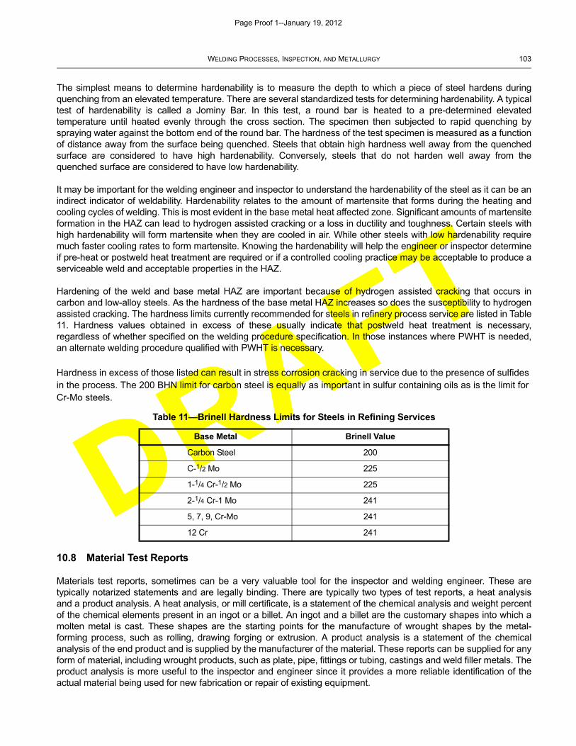
DRAFT
WELDING PROCESSES, INSPECTION, AND METALLURGY 103
The simplest means to determine hardenability is to measure the depth to which a piece of steel hardens duringquenching from an elevated temperature. There are several standardized tests for determining hardenability. A typicaltest of hardenability is called a Jominy Bar. In this test, a round bar is heated to a pre-determined elevatedtemperature until heated evenly through the cross section. The specimen then subjected to rapid quenching byspraying water against the bottom end of the round bar. The hardness of the test specimen is measured as a functionof distance away from the surface being quenched. Steels that obtain high hardness well away from the quenchedsurface are considered to have high hardenability. Conversely, steels that do not harden well away from thequenched surface are considered to have low hardenability.
It may be important for the welding engineer and inspector to understand the hardenability of the steel as it can be anindirect indicator of weldability. Hardenability relates to the amount of martensite that forms during the heating andcooling cycles of welding. This is most evident in the base metal heat affected zone. Significant amounts of martensiteformation in the HAZ can lead to hydrogen assisted cracking or a loss in ductility and toughness. Certain steels withhigh hardenability will form martensite when they are cooled in air. While other steels with low hardenability requiremuch faster cooling rates to form martensite. Knowing the hardenability will help the engineer or inspector determineif pre-heat or postweld heat treatment are required or if a controlled cooling practice may be acceptable to produce aserviceable weld and acceptable properties in the HAZ.
Hardening of the weld and base metal HAZ are important because of hydrogen assisted cracking that occurs incarbon and low-alloy steels. As the hardness of the base metal HAZ increases so does the susceptibility to hydrogenassisted cracking. The hardness limits currently recommended for steels in refinery process service are listed in Table11. Hardness values obtained in excess of these usually indicate that postweld heat treatment is necessary,regardless of whether specified on the welding procedure specification. In those instances where PWHT is needed,an alternate welding procedure qualified with PWHT is necessary.
Hardness in excess of those listed can result in stress corrosion cracking in service due to the presence of sulfides in the process. The 200 BHN limit for carbon steel is equally as important in sulfur containing oils as is the limit for Cr-Mo steels.
10.8 Material Test Reports
Materials test reports, sometimes can be a very valuable tool for the inspector and welding engineer. These aretypically notarized statements and are legally binding. There are typically two types of test reports, a heat analysisand a product analysis. A heat analysis, or mill certificate, is a statement of the chemical analysis and weight percentof the chemical elements present in an ingot or a billet. An ingot and a billet are the customary shapes into which amolten metal is cast. These shapes are the starting points for the manufacture of wrought shapes by the metal-forming process, such as rolling, drawing forging or extrusion. A product analysis is a statement of the chemicalanalysis of the end product and is supplied by the manufacturer of the material. These reports can be supplied for anyform of material, including wrought products, such as plate, pipe, fittings or tubing, castings and weld filler metals. Theproduct analysis is more useful to the inspector and engineer since it provides a more reliable identification of theactual material being used for new fabrication or repair of existing equipment.
Table 11—Brinell Hardness Limits for Steels in Refining Services
Base Metal Brinell Value
Carbon Steel 200
C-1/2 Mo 225
1-1/4 Cr-1/2 Mo 225
2-1/4 Cr-1 Mo 241
5, 7, 9, Cr-Mo 241
12 Cr 241
Page Proof 1--January 19, 2012
DRAFT
104 API RECOMMENDED PRACTICE 577
For the purposes of this publication, the information about material test reports pertains to product certificates forcarbon, low-alloy steel and stainless steels. However, it should be noted that the material test report documents mayinclude, but are not limited to, the following information:
a) manufacturer of the heat of material;
b) date of manufacture;
c) heat number of the material;
d) applicable national standard(s) to which the heat conforms, such as ASTM, ASME, or MIL-STD;
e) heat treatment, if applicable;
f) chemistry of the heat;
g) mechanical properties, at a minimum those required by the applicable National Standards;
h) any other requirement specified by the applicable National Standard;
i) any supplemental information or testing requested by the purchaser, this may include, but is not limited to:
1) impact strength;
2) ductile to brittle transition temperature determination;
3) fracture toughness;
4) elevated mechanical property testing (i.e. tensile, hot ductility or creep testing);
5) hardenability;
6) hardness;
7) response to heat treatment (i.e. proposed post fabrication heat treatment such as precipitation hardening,necessary to achieve mechanical properties);
8) microstructural analysis, such as grain size evaluation;
9) non-destructive examination, such as ultrasonic testing.
The inspector should review the material test report to confirm that the material(s) being used for fabrication of newequipment or repair of existing equipment meet the requirements specified by the user. The welding engineer canalso use the information from a materials test report to determine the weldability of the materials to be used, and torecommend proper welding procedures, pre-heat and/or postweld heat treatment. The chemical analysis given in thetest report can be used to calculate the carbon equivalent for that material. It is important to note that materials testreports are not generally supplied to the purchaser unless requested. It is good practice for the purchaser to requestthe mill test reports.
10.9 Weldability of Metals
10.9.1 General
There are entire books devoted to the weldability of metals and alloys. Weldability is a complicated property that doesnot have a universally accepted definition. The term is widely interpreted by individual experience. The AmericanWelding Society defines weldability as “the capacity of a metal to be welded under the fabrication conditions imposed,
Page Proof 1--January 19, 2012
DRAFT
WELDING PROCESSES, INSPECTION, AND METALLURGY 105
into a specific, suitably designed structure, and to perform satisfactorily in the intended service.” Weldability is relatedto many factors including the following:
a) the metallurgical compatibility of the metal or alloy being welded, which is related to the chemical composition andmicrostructure of the metal or alloy, and the weld filler metal used;
b) the specific welding processes being used to join the metal;
c) the mechanical properties of the metal, such as strength, ductility and toughness;
d) the ability of the metal to be welded such that the completed weld has sound mechanical properties;
e) weld joint design.
10.9.2 Metallurgy and Weldability
A primary factor affecting weldability of metals and alloys is their chemical composition. Chemical composition notonly controls the range of mechanical properties in carbon and alloy steels, it has the most influence on the effects ofwelding on the material. The heat cycles from welding in effect produce a heat treatment on the metal that can have asubstantial effect on mechanical properties, depending on the chemical composition of the metal being welded. Asnoted earlier, each type of metal has welding procedural limits within which sound weldments with satisfactoryproperties can be fabricated. If these limits are wide, the metal is said to have good weldability. If the limits are narrow,the metal is considered to have poor weldability.
The addition of carbon generally makes the metal more difficult to weld without cracking. Carbon content has thegreatest effect on mechanical properties, such as tensile strength, ductility and toughness in the base metal heataffected zone and weldment. Carbon content influences the susceptibility of the metal to delayed cracking problemsfrom hydrogen. The carbon content, or carbon equivalent, of carbon steel determines the necessity for pre-heat andpostweld heat treatment.
Alloying elements other than carbon are added to alloy steels for various reasons and can have an influence on theweldability of the metal. Some alloying elements, such as manganese, chromium, nickel and molybdenum are addedto provide beneficial effects on strength, toughness, and corrosion resistance. Some of these elements are beneficialin non-heat treated steel while others come into play during heat treatments necessary to produce the desiredmechanical properties. These alloying elements can have a strong effect on hardenability, so they can also affect theweldability of the metal being welded.
There are some elements present in carbon and alloy steels that are not deliberately added that can have an affect onweldability. These include sulfur, phosphorus, tin, antimony, and arsenic. These elements will sometimes be referredto as tramp elements.
One tool has been developed to help evaluate the weldability of carbon and alloy steel and that is the carbonequivalent (CE) equation. The CE calculates a theoretical carbon content of the metal and takes into account not onlycarbon, but also the effect of purposely added alloying elements and tramp elements. Several different equations forexpressing carbon equivalent are in use. One common equation is:
Typically, steels with a CE less than 0.35 require no preheat. Steels with a CE of 0.35 to 0.55 usually requirepreheating, and steels with a CE greater than 0.55 require both preheating and a PWHT. However, requirements forpreheating should be evaluated by considering other factors such as hydrogen level, humidity, and section thickness.
CE CMn6-------- Cr Mo V+ +( )
5----------------------------------- SI Ni Cu+ +( )
15-----------------------------------+ + +=
Page Proof 1--January 19, 2012
DRAFT
106 API RECOMMENDED PRACTICE 577
10.9.3 Weldability Testing
One of the best means to determine weldability of a metal or combination of metals is to perform direct weldabilitytesting. Direct tests for weldability are defined as those tests that specify welding as an essential feature of the testspecimen. Weldability testing provides a measure of the changes induced by welding in a specified steel property andto evaluate the expected performance of welded joints.
The problem with predicting the performance of structures or welded equipment from a laboratory type test is acomplex one since size, configuration, environment and type of loading normally differ. For this reason, no single testcan be expected to measure all of the aspects of a property as complex as weldability and most weldments areevaluated by several tests. If tests are to be useful in connection with fabrication, they should be designed to measurethe susceptibility of the weld metal-base metal system to such defects as weld metal or base metal cracks, lamellartearing, and porosity or inclusions under realistic and properly controlled conditions of welding. Selection of a testmethod may also have to balance time and cost for emergency repairs or shutdown work.
The simplest weldability tests are those that evaluate the strength and ductility of the weld. Tests that evaluatestrength include weld tension tests, shear strength, and hardness. Ductility and fracture toughness tests include bendtests and impact tests. These tests evaluate the breaking strength, ductility and toughness of simple weld joints.These tests are the same as tests used for welding procedure and welder qualification to the ASME Boiler andPressure Vessel Code. If the weldment has adequate strength and ductility, it is usually deemed acceptable forservice.
Fabrication weldability tests that incorporate welding into their execution can be broadly classified as restraintcracking tests, lamellar tearing tests, externally loaded cracking tests, underbead cracking tests or simple weld metalsoundness tests. Some of these tests can be used to detect the susceptibility to more than one type of defect, whileothers are intended as single purpose tests and still others may be go/no-go types of tests.
Weld restraint induces stresses that can contribute to cracking of both the weld and base metal in fabrication welds.This type of cracking occurs when the rigidity of the joint is so severe that the base metal or weld metal strengthcannot resist the strains and stresses applied by expansion and contraction of the weld joint. Weld restraint crackingspecimen are designed to permit a quantitative variation in restraint under realistic welding conditions so thecontribution of the weld metal, base metal and welding processes can be evaluated with respect to contribution tocracking. Typical weld restraint test methods include the Lehigh restraint test, slot test, rigid restraint cracking (RRC)test, and circular weld restraint cracking test.
Another approach to measuring susceptibility to weld cracking is to apply an external load during welding orsubsequent to welding. The loading is intended to duplicate or magnify stresses from restraint of a rigid weld joint.The tests provide an ability to control the stress and strain applied to the weld joint and, therefore, provide a relativeindex of the susceptibility to weld cracking. Test methods that use external loading include the implant test, tensionrestraint cracking (TRC) test, and varestraint test. There is also a very specialized test called the Gleeble test thatalso applies a load to the specimen during heating or melting of the metal.
It is beyond to the scope of this document to describe each test in detail; however, a general overview of differenttypes of tests and what types of defects they can detect are given in Table 12.
10.10 Weldability of high-alloys
10.10.1 General
This section will give information about welding of high-alloy metals, such as austenitic stainless steels, precipitationhardening stainless steels and nickel based alloys. These materials are not as common as carbon and low-alloysteels (e.g. 11/4 Cr-1/2 Mo through 9 Cr-1 Mo steels), but may still be used in some processes within the oil industry.
Page Proof 1--January 19, 2012
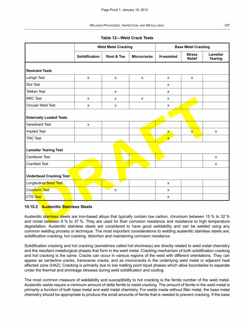
DRAFT
WELDING PROCESSES, INSPECTION, AND METALLURGY 107
10.10.2 Austenitic Stainless Steels
Austenitic stainless steels are iron-based alloys that typically contain low carbon, chromium between 15 % to 32 %and nickel between 8 % to 37 %. They are used for their corrosion resistance and resistance to high temperaturedegradation. Austenitic stainless steels are considered to have good weldability and can be welded using anycommon welding process or technique. The most important considerations to welding austenitic stainless steels are;solidification cracking, hot cracking, distortion and maintaining corrosion resistance.
Solidification cracking and hot cracking (sometimes called hot shortness) are directly related to weld metal chemistryand the resultant metallurgical phases that form in the weld metal. Cracking mechanism of both solidification crackingand hot cracking is the same. Cracks can occur in various regions of the weld with different orientations. They canappear as centerline cracks, transverse cracks, and as microcracks in the underlying weld metal or adjacent heataffected zone (HAZ). Cracking is primarily due to low melting point liquid phases which allow boundaries to separateunder the thermal and shrinkage stresses during weld solidification and cooling.
The most common measure of weldability and susceptibility to hot cracking is the ferrite number of the weld metal.Austenitic welds require a minimum amount of delta ferrite to resist cracking. The amount of ferrite in the weld metal isprimarily a function of both base metal and weld metal chemistry. For welds made without filler metal, the base metalchemistry should be appropriate to produce the small amounts of ferrite that is needed to prevent cracking. If the base
Table 12—Weld Crack Tests
Weld Metal Cracking Base Metal Cracking
Solidification Root & Toe Microcracks H-assistedStress Relief
Lamellar Tearing
Restraint Tests
Lehigh Test x x x x x
Slot Test x
Tekken Test x x
RRC Test x x x x
Circular Weld Test x x x
Externally Loaded Tests
Varestraint Test x
Implant Test x x x
TRC Test x
Lamellar Tearing Test
Cantilever Test x
Cranfield Test x
Underbead Cracking Test
Longitudinal Bead Test x
Cruciform Test x x
CTS Test x
Page Proof 1--January 19, 2012
DRAFT
108 API RECOMMENDED PRACTICE 577
metal chemistry will not allow for ferrite formation, then filler metal is recommended to produce adequate ferrite in theweld metal. Welding parameters and practices can also effect ferrite formation. For example, small amounts ofnitrogen absorbed into the weld metal can reduce ferrite formation. WRC Bulletin 342 contains diagrams thataccurately predict the amount of ferrite present in a weld metal based on the calculation of nickel and chromiumequivalents based on weld metal and base metal chemistry. A number of resources recommend a minimum of 5% –20 % ferrite to prevent cracking.
Weldability of austenitic stainless steels can also be affected by the presence of high levels of low melting pointelements like sulfur, phosphorus, and selenium. Other elements such as silicon and columbium (niobium) will alsoincrease the hot cracking susceptibility of austenitic stainless steels.
Distortion is more often a problem with welding of austenitic stainless steels than carbon or low-alloy steels. Thethermal conductivity of austenitic stainless steels is about one third that of carbon steel and the coefficient of thermalexpansion is about 30 % greater. This means that distortion is greater for austenitic stainless steels than for carbonsteels. More frequent tack welds may be necessary for stainless steels to limit shrinkage.
Welding can reduce the corrosion resistance of regions of the HAZ of some austenitic stainless steels. Areas exposedto temperatures between 800 °F to 1650 °F (427 °C to 900 °C) for a long enough time may precipitate chromiumcarbides at the grain boundaries. This causes a loss of corrosion resistance due to chromium depletion. Using low-carbon content stainless steels, such as Type 304L or 316L, or stabilized grades of stainless steels, such as Type 321and 347 can prevent this phenomenon. It is also important to select the proper filler metal to prevent a loss incorrosion resistance. Low carbon electrodes or stabilized grades of bare filler metal should be used.
Oxidation of the backside of welds made without proper shielding can also be detrimental to the corrosion resistanceof austenitic stainless steels. To prevent a loss in corrosion resistance the root of the weld should be protected byusing an inert backing gas.
10.10.3 Nickel Alloys
Nickel alloys, such as Alloy C276 or Alloy 625 suffer from similar problems as austenitic stainless steels. In generalmost nickel alloy materials are considered to have less weldability than austenitic stainless steels. Some nickel alloys,such as Alloy 825, 600, and 625 have similar welding characteristic to austenitic stainless steels. While Alloy 200,Alloy 400, and Alloy B-2 will have very different welding characteristics compared to austenitic stainless steels.
One of the main differences between nickel alloy and carbon steels, and austenitic stainless steels, is their tendencyto be sluggish during welding. This means for nickel alloys that the molten weld pool will not move as easily as it doesfor other metals. This sluggish tendency means the welder should move the weld pool with a weave or oscillationpattern to ensure good sidewall fusion. If some oscillation is not used, a high convex weld contour will result whichcause sidewall lack of fusion, weld undercut or slag inclusions. The formation of a slightly concave weld bead profilewill be more resistant to centerline cracking. It is also important that the bevel angle for nickel alloys be wide enoughto allow for this necessary oscillation of the welding torch. The wider weld bevel will also be beneficial with respect toweld penetration. Nickel alloys also suffer from shallower weld penetration as compared to carbon steels andaustenitic stainless steel. To overcome this, the weld joint is modified by having a wider bevel and thinner root face.
Nickel alloys are also susceptible to hot cracking, in some cases more so than austenitic stainless steels. This hottearing will occur as the weld pool cools and solidifies. To help prevent hot cracking the weld joint should be designedto minimize restraint and the weld should be allowed to cool as quickly as possible. The faster a nickel alloy weldsolidifies (freezes), the less time it spends in the temperature range where it can tear. For this reason pre-heating,which slows down the cooling rate of the weld, is actually harmful, as it permits more opportunity for hot tearing tooccur.
As with austenitic stainless steels, the weldability of nickel alloys can also be affected by the presence of high levelsof low melting point elements like sulfur, phosphorus, zinc, copper and lead. All of these contaminants can lead tocracking in either the weld or base metal.
Page Proof 1--January 19, 2012
DRAFT
WELDING PROCESSES, INSPECTION, AND METALLURGY 109
11 Refinery and Petrochemical Plant Welding Issues
11.1 General
This section provides details of specific welding issues encountered by the inspector in refineries and petrochemicalplants. This section will be expanded as more issues reflecting industry experience are added.
11.2 Hot Tapping and In-Service Welding
11.2.1 General
API 2201 provides an in depth review of the safety aspects to be considered when hot tapping or welding on in-service piping or equipment. Prior to performing this work, a detailed written plan should be developed and reviewed.The following is a brief summary of welding related issues.
Two primary concerns when welding on in-service piping and equipment are burn through and cracking. Burn throughwill occur if the unmelted area beneath the weld pool can no longer contain the pressure within the pipe or equipment.Weld cracking results when fast weld-cooling rates produce a hard, crack-susceptible weld microstructure. Fastcooling rates can be caused by flowing contents inside the piping and equipment, which remove heat quickly.
11.2.2 Electrode Considerations
Hot tap and in-service welding operations should be carried out only with low-hydrogen consumables and electrodes(e.g. E7016, E7018, and E7048). Extra-low-hydrogen consumables such as Exxxx-H4 should be used for weldingcarbon steels with CE greater than 0.42 % or where there is potential for hydrogen assisted cracking (HAC) such ascold worked pieces, high strength, and highly constrained areas.
Cellulosic type electrodes (e.g. E6010, E6011, or E7010) may be used for root and hot passes. Although low-hydrogen electrodes are preferred, some refining locations and the pipeline industry prefer to use cellulosicelectrodes frequently because they are easy to operate and provide improved control over the welding arc. Root passwith low-hydrogen electrodes reduces risk of HAC. It also reduces risk of burn-through because the amount of heatdirected to the base metal is less than when using cellulosic type electrodes. However, manipulation of low-hydrogenelectrode for root pass is not as easy but it can be done by training and practice. It should be noted that cellulosicelectrodes have the following adverse effects on the integrity of the weldment:
a) Deep penetration, therefore higher risk of burn-through than low-hydrogen electrodes; and
b) High diffusible hydrogen, therefore higher risk of hydrogen assisted cracking.
11.2.3 Flow Rates
Under most conditions, it is desirable to maintain some product flow inside of any material being welded. This helps todissipate the heat and to limit the metal temperature during the welding operation, thereby reducing the risk of burn-through. Liquid flow rates in piping should be between 1.3 ft/sec. and 4.0 ft/sec. (0.4 m/sec. and 1.3 m/sec.). Fasterliquid flow rates may cool the weld area too quickly and thereby cause hard zones that are susceptible to weldcracking or low toughness properties in the weldment. Because this is not a problem when the pipe contains gases,there is no need to specify a maximum velocity. If the normal flow of liquids exceeds these values or if the flow coolsthe metal to below dew point, it is advisable to compensate by preheating the weld area to at least 70 °F (20 °C) andmaintaining that temperature until the weld has been completed. High liquid flow may cause rapid cooling of the weldarea during the welding, creating hard zones susceptible to cracking. Under these circumstances, the minimuminterpass temperatures may not be attainable, resulting in undesirable material properties.
Page Proof 1--January 19, 2012

DRAFT
110 API RECOMMENDED PRACTICE 577
For making attachment welds to equipment containing a large quantity of liquid such as a storage tank 36 in. (0.9 m)below the liquid/vapor line, normal circulation will effectively cool the weld area.
Welding on a line under no-flow conditions or intermittent-flow conditions, e.g. a flare line, should not be attemptedunless it has been confirmed that no explosive or flammable mixture will be generated during the welding operation.In this respect, it should be confirmed that no ingress of oxygen in the line is possible. In cases where thisrequirement cannot be met, inert gas or nitrogen purging is recommended.
An appropriate flow rate should be maintained to minimize the possibility of burn-through or combustion. Theminimum flow rate is 1.3 ft/sec. (0.4 m/sec.) for liquid and gas. For liquids, the maximum flow rate is usually requiredto minimize risk of high hardness weld zone due to fast cooling rate. The allowable maximum flow rate depends onthe process temperature. In general, 4.0 ft/sec. (1.2 m/sec.) is the upper limit. There is no restriction on maximumvelocity for gas lines, subject to maintaining preheat temperatures.
11.2.4 Other Considerations
11.2.4.1 Burn Through
To avoid overheating and burn through, the welding procedure specification should be based on experience inperforming welding operations on similar piping or equipment, and/or be based on heat transfer analysis. Many usersestablish procedures detailing the minimum wall thickness that can be hot tapped or welded in-service for a given setof conditions like pressure, temperature, and flow rate. Some users include in their procedures the use of mock-upweld coupons when the actual thickness of the material to be welded is less than 1/4 in. The mock-up couponrepresents the actual material and thickness, the welding parameters are recorded and the weld penetration isverified by etching. This information becomes the supplement to the repair package. To minimize burn through, thefirst weld pass to equipment or piping less than 1/4 in. (6.35 mm) thick should be made with 3/32 in. (4.76 mm) orsmaller diameter welding electrode to limit heat input. For equipment and piping wall thicknesses where burn throughis not a primary concern, a larger diameter electrode can be used. Weaving the bead should also be avoided as thisincreases the heat input.
11.2.4.2 Hot Taps
Adverse effects can also occur from the heat on the process fluid. In addition, welds associated with hot taps or in-service welding often cannot be stress relieved and may be susceptible to cracking in certain environments. Any hottapping or in-service welding on systems containing those listed in Table 13 should be carefully reviewed.
During repairs or alterations (including hot taps) of alloy material piping systems, material verification of the existingand the new materials is required to establish that the selected components are as specified. Additionally, in somejurisdictions the hot tap component may require to have a registered design in which case this should be verified.
Buttering the surface of the run pipe prior to attaching a hot-tap nozzle is particularly recommended when attaching anozzle to pipe fabricated from plate material to prevent lamellar tearing of the pipe where the thickness is such thatthis may occur as the result of weld shrinkage stresses. With in-service welding there is the risk of high hardness andhydrogen cracking in the HAZ of the parent material. Buttering allows a more closely controlled heat input in theparent material, and also permits use of the temper bead welding technique. The temper bead welding techniquetempers the HAZ of the parent material during the deposition of the second layer of weld metal. This approach isparticularly useful where the cooling effect of the process fluid present is high.
Buttering allows a balanced welding sequence to be used, and if correctly applied can reduce the potential distortionof the pipe after welding. Normally, two layers of weld metal should be deposited especially for dissimilar metal weldsto reduce the impact of weld dilution. The final thickness of the weld deposit at the location of the nozzle-to-pipe weldshould, after grinding, be not less than 1/4 in. (3 mm). The width of the buttering should be sufficient to overlap thenozzle attachment weld by 1/4 in. (6.5 mm) on both the inside and outside diameters. Similarly, buttering should bedeposited under any reinforcement plate-to-pipe welds.
Page Proof 1--January 19, 2012
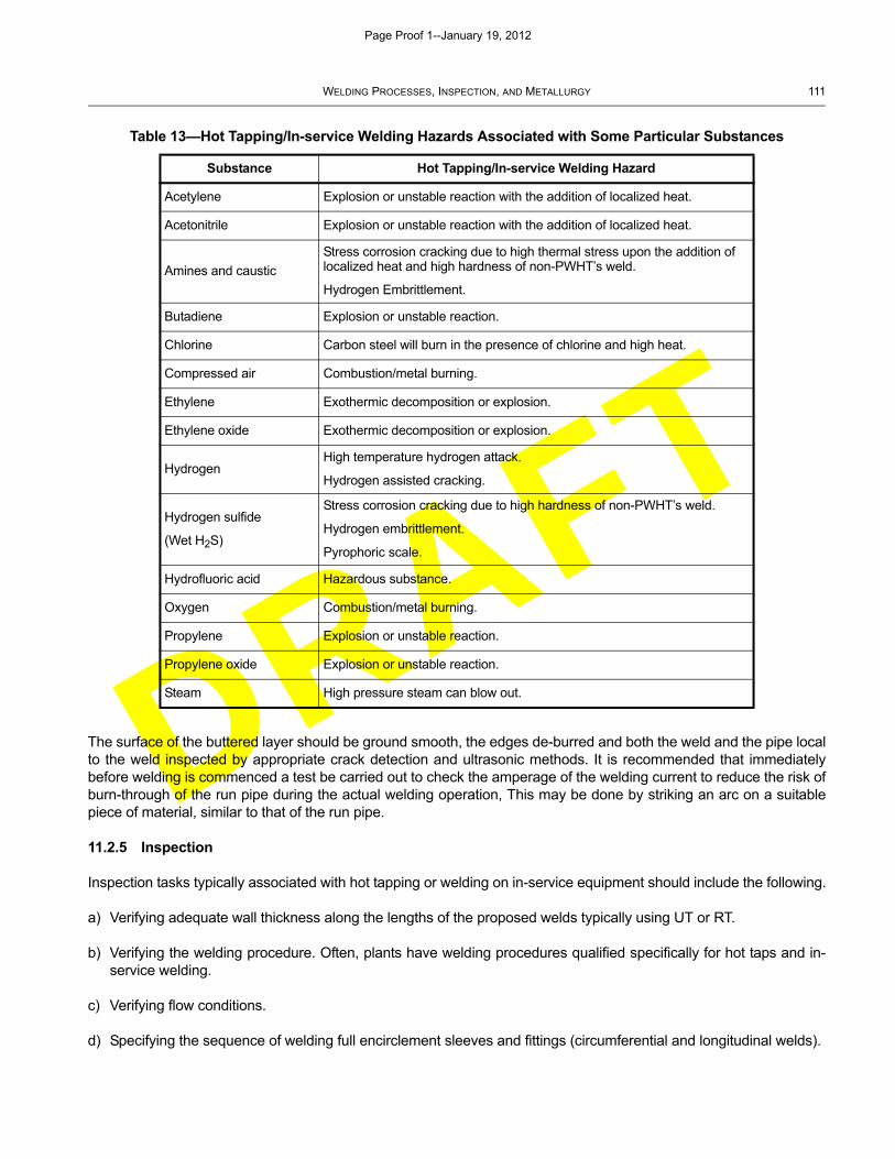
DRAFT
WELDING PROCESSES, INSPECTION, AND METALLURGY 111
The surface of the buttered layer should be ground smooth, the edges de-burred and both the weld and the pipe localto the weld inspected by appropriate crack detection and ultrasonic methods. It is recommended that immediatelybefore welding is commenced a test be carried out to check the amperage of the welding current to reduce the risk ofburn-through of the run pipe during the actual welding operation, This may be done by striking an arc on a suitablepiece of material, similar to that of the run pipe.
11.2.5 Inspection
Inspection tasks typically associated with hot tapping or welding on in-service equipment should include the following.
a) Verifying adequate wall thickness along the lengths of the proposed welds typically using UT or RT.
b) Verifying the welding procedure. Often, plants have welding procedures qualified specifically for hot taps and in-service welding.
c) Verifying flow conditions.
d) Specifying the sequence of welding full encirclement sleeves and fittings (circumferential and longitudinal welds).
Table 13—Hot Tapping/In-service Welding Hazards Associated with Some Particular Substances
Substance Hot Tapping/In-service Welding Hazard
Acetylene Explosion or unstable reaction with the addition of localized heat.
Acetonitrile Explosion or unstable reaction with the addition of localized heat.
Amines and caustic
Stress corrosion cracking due to high thermal stress upon the addition of localized heat and high hardness of non-PWHT’s weld.
Hydrogen Embrittlement.
Butadiene Explosion or unstable reaction.
Chlorine Carbon steel will burn in the presence of chlorine and high heat.
Compressed air Combustion/metal burning.
Ethylene Exothermic decomposition or explosion.
Ethylene oxide Exothermic decomposition or explosion.
HydrogenHigh temperature hydrogen attack.
Hydrogen assisted cracking.
Hydrogen sulfide
(Wet H2S)
Stress corrosion cracking due to high hardness of non-PWHT’s weld.
Hydrogen embrittlement.
Pyrophoric scale.
Hydrofluoric acid Hazardous substance.
Oxygen Combustion/metal burning.
Propylene Explosion or unstable reaction.
Propylene oxide Explosion or unstable reaction.
Steam High pressure steam can blow out.
Page Proof 1--January 19, 2012
DRAFT
112 API RECOMMENDED PRACTICE 577
e) Verifying fit-up of the hot tap fitting.
f) Auditing welding to assure the welding procedure is being followed.
g) Perform NDE of completed welds. Typically this includes VT, UT shear wave using special procedures for the jointconfiguration, MT or PT as applicable for material and temperature.
h) Witness leak testing of fitting, if specified.
i) Perform positive metal identification (PMI) testing on the hot tap component material. Additionally, in somejurisdictions the hot tap component may require to have a registered design in which case this should be verified.
11.3 Lack of Fusion with GMAW-S Welding Process
The gas metal arc welding (GMAW) process can utilize various metal transfer modes. When using the low voltage,short circuiting mode (designated by the -S extension), the molten weld puddle is able to freeze more quickly. Thisallows the unique ability to weld out of position, to weld thin base metals, and to weld open butt root passes. Due tothis inherent nature of the welding process the BPV Code Section IX, restricts this process by:
a) requiring welders qualify with mechanical testing rather than by radiographic examination.
b) limiting the base metal thickness qualified by the procedure to 1.1 times the test coupon thickness for couponsless than 1/2 in. thick (12.7 mm) per variable QW-403.10.
c) limiting the deposited weld metal thickness qualified by the procedure to 1.1 times the deposited thickness forcoupons less than 1/2 in. thick (12.7 mm) per variable QW-404-32.
d) making variable QW-409.2 an essential variable when qualifying a welder for the GMAW-S process.
Since the transfer mode may be difficult to determine without an oscilloscope, some general characteristics are listedin a National Board Classic Bulletin, Low Voltage Short Circuiting—GMAW, from January 1985, to assist the inspectorin determining the transfer mode being used. The quick freeze characteristic, which can result in LOF, is the reasonthis process is frequently written out of purchase requisitions.
GMAW in the short-circuiting transfer mode is of particular significance to inspectors in that many specifications,codes and standards impose limitations or special conditions on its use. The technique can suffer from incompletefusion particularly in the sidewall of steep or narrow weld preparations. This occurs as transfer of small fast freezingdroplets only occurs whilst the electrode is short circuited by contact with the work piece. Intermittent loss of contactcan leave areas of lack of fusion. In shallow weld preparations, these are also very difficult to detect with conventionalradiographic techniques. Consequently, a higher standard of NDE inspection is required. In pipeline welding,automated ultrasonic has been adopted to overcome this problem. The risk of LOF associated with GMAW-S meansrestrictions on qualification of welders using radiography only and inspectors should make note of these potentialproblems.
11.4 Caustic Service
Carbon steel and low alloy steels are subject to stress corrosion cracking in caustic service. Austenitic (i.e. Type-300series) stainless steels can be sensitive to caustic cracking in high temperature steam environments. Cracking is afunction of temperature, caustic concentration, and the level of operating or residual stress. Prior to welding or PWHT,the weld area should be cleaned, for a distance of at least 6 in. (150 mm) from the edges of the weld, with a 5 %acetic acid solution in water and then water wash to removed the neutralized caustic. Check the cleaned area with pHpaper to show that the caustic has been removed. Alternatively, the area can be checked with a phenolphthaleinindicator to show that caustic has been removed. If the indicator turns pink, caustic is still present on the surface. Thecontaminated surface should be reneutralized, recleaned and rechecked, as necessary, until caustic is removed from
Page Proof 1--January 19, 2012
DRAFT
WELDING PROCESSES, INSPECTION, AND METALLURGY 113
the surface. Material cleanliness is a very important requirement for successful welding, especially when weldingnickel and nickel alloy materials. Inspection should be performed before welding on caustic contaminated surfaces.All areas to be welded should be ground or power-brush clean. Nickel and nickel alloys should be cleaned with astainless steel wire brush. All cleaning tools including wire brushes and carbide grinding tools should be clean andfree of debris or other metal fragments. Care should be taken during grinding operations since the heat of grindingmay create and propagate crack-like defects on caustic-contaminated surfaces.
Welds and steel cold formed areas should be postweld heat treated if service conditions are anticipated to exceed120 °F (49 °C) for 50 % caustic soda solution. Cracking can be effectively prevented by means of a stress-relievingheat treatment (e.g. PWHT). Heat treatment, at or above 1150 °F, is considered an effective stress relieving heattreatment for carbon steel to resist caustic stress corrosion cracking. Although caustic stress corrosion cracks may beseen visually, crack detection is best performed with WFMT, ET, RT, or ACFM techniques. Surface preparation by gritblasting, high pressure water blasting, or other methods is usually required.
Prior to weld repairs in caustic service, a corrosion specialist should review the details of welding plan to assuresuitability for service. This should include a review of the welding electrode/wire selected, the weld procedure, detailsof weld preparation, post-weld heat treatment, and the details of the NDE to be used on the completed welds. Otherservice that may warrant similar review include amine service, hydrofluoric acid service, hydrogen service, sour andwet H2S service, and situations with dissimilar metal welds.
Page Proof 1--January 19, 2012
DRAFT
114
Annex A(normative)
Terminology and Symbols
A.1 Weld Joint Types
Figure A.1 illustrates the various weld joint types that are typically encountered by the inspector. The type of joint canaffect the type of weld process that can be used and on choice of NDE method.
A.2 Weld Symbols
Engineering and construction drawings often use standard symbols to represent weld details. Figure A.2 shows thecorresponding symbols for several weld joint types. Figure A.3 shows some supplementary symbols that providespecific detail about the weld. Figure A.4 explains the conventions used in a weld symbol.
A.3 Weld Joint Nomenclature
Standard terminology applies to the various components of a weld joint. Figure A.5 illustrates and describes the jointterminology.
A.4 Electrode Identification
The AWS specification and classification system allows selection of an electrode, which will provide a weld metal withspecific mechanical properties and alloy composition. The following welding processes use an electrode identificationsystem to designate characteristics of the electrode: SMAW, GMAW, GTAW, FCAW, SAW, and EGW. Theidentification systems are explained for each process in Figure A.6, Figure A.7, Figure A.8, Figure A.9, and FigureA.10.
Page Proof 1--January 19, 2012
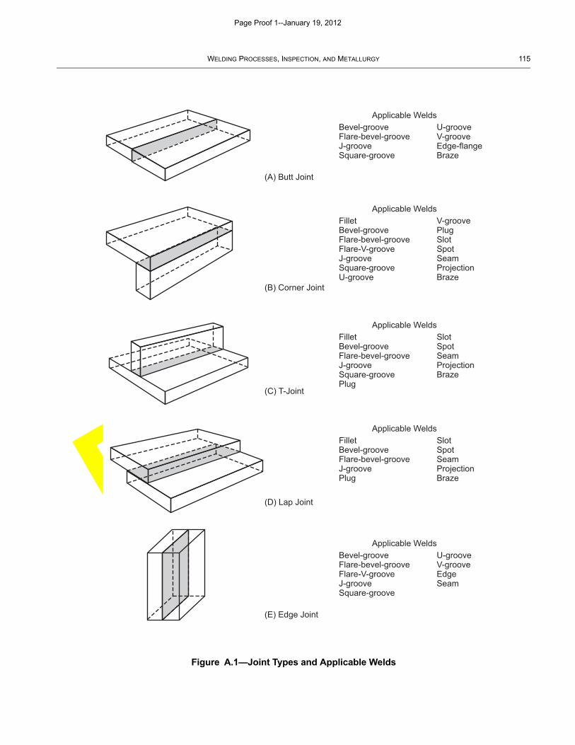
DRAFT
WELDING PROCESSES, INSPECTION, AND METALLURGY 115
Figure A.1—Joint Types and Applicable Welds
Applicable WeldsBevel-grooveFlare-bevel-grooveJ-grooveSquare-groove
(A) Butt Joint
(B) Corner Joint
(C) T-Joint
(D) Lap Joint
(E) Edge Joint
U-grooveV-grooveEdge-flangeBraze
Applicable WeldsFilletBevel-grooveFlare-bevel-grooveFlare-V-grooveJ-grooveSquare-grooveU-groove
V-groovePlugSlotSpotSeamProjectionBraze
Applicable WeldsFilletBevel-grooveFlare-bevel-grooveJ-grooveSquare-groovePlug
SlotSpotSeamProjectionBraze
Applicable WeldsFilletBevel-grooveFlare-bevel-grooveJ-groovePlug
SlotSpotSeamProjectionBraze
Applicable WeldsBevel-grooveFlare-bevel-grooveFlare-V-grooveJ-grooveSquare-groove
U-grooveV-grooveEdgeSeam
Page Proof 1--January 19, 2012
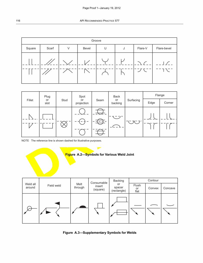
DRAFT
116 API RECOMMENDED PRACTICE 577
Figure A.2—Symbols for Various Weld Joint
Figure A.3—Supplementary Symbols for Welds
Groove
Square Scarf V Bevel U J Flare-V Flare-bevel
FilletPlug
orslot
Stud Seam
NOTE The reference line is shown dashed for illustrative purposes.
Surfacing
Flange
Edge Corner
Spotor
projection
Backor
backing
Weld allaround Field weld Melt
throughConsumable
insert(square)
Backingor
spacer(rectangle)
Flushorflat
Convex
Contour
Concave
Page Proof 1--January 19, 2012
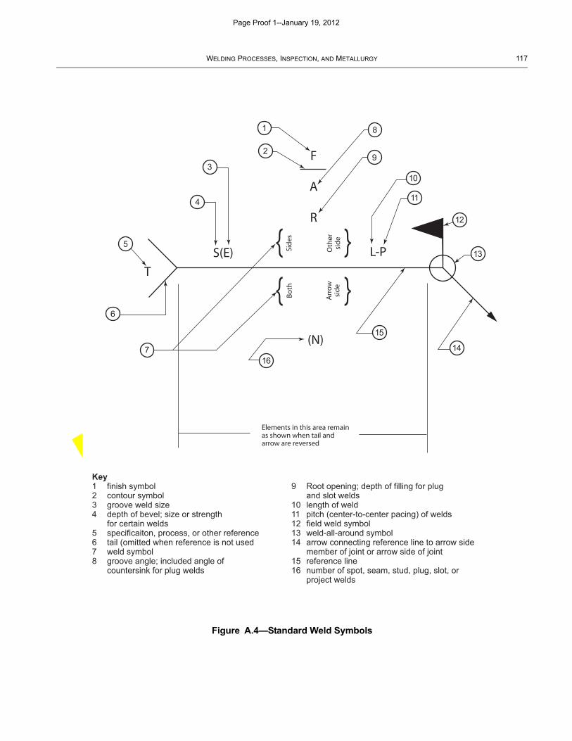
DRAFT
WELDING PROCESSES, INSPECTION, AND METALLURGY 117
Figure A.4—Standard Weld Symbols
Elements in this area remainas shown when tail andarrow are reversed
Side
s
Oth
ersi
de
Both
Arr
owsi
de(N)
S(E)T
L-P
F
A
R
Key1 finish symbol2 contour symbol3 groove weld size4 depth of bevel; size or strength for certain welds5 specificaiton, process, or other reference6 tail (omitted when reference is not used7 weld symbol8 groove angle; included angle of countersink for plug welds
9 Root opening; depth of filling for plug and slot welds10 length of weld11 pitch (center-to-center pacing) of welds12 field weld symbol13 weld-all-around symbol14 arrow connecting reference line to arrow side member of joint or arrow side of joint15 reference line16 number of spot, seam, stud, plug, slot, or project welds
1
2
3
4
5
6
7
8
9
10
11
12
13
14
15
16
Page Proof 1--January 19, 2012
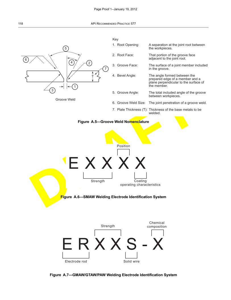
DRAFT
118 API RECOMMENDED PRACTICE 577
Figure A.5—Groove Weld Nomenclature
Figure A.6—SMAW Welding Electrode Identification System
Figure A.7—GMAW/GTAW/PAW Welding Electrode Identification System
6
5
4 2
13
7
T
Groove Weld
1. Root Opening:
2. Root Face:
3. Groove Face:
4. Bevel Angle:
5. Groove Angle:
6. Groove Weld Size:
7. Plate Thickness (T):
A separation at the joint root between the workpieces.
That portion of the groove face adjacent to the joint root.
The surface of a joint member included in the groove.
The angle formed between the prepared edge of a member and a plane perpendicular to the surface of the member.
The total included angle of the groove between workpieces.
The joint penetration of a groove weld.
Thickness of the base metals to be welded.
Key
E X X X XPosition
Strength Coatingoperating characteristics
E R X X S - XStrength
Chemicalcomposition
Solid wireElectrode rod
Page Proof 1--January 19, 2012
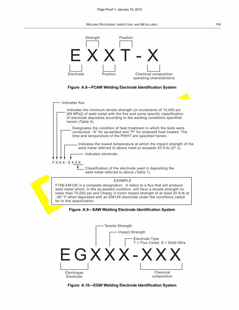
DRAFT
WELDING PROCESSES, INSPECTION, AND METALLURGY 119
Figure A.8—FCAW Welding Electrode Identification System
Figure A.9—SAW Welding Electrode Identification System
Figure A.10—EGW Welding Electrode Identification System
E X X T - XPositionStrength
Electrode Position Chemical compositionoperating characteristics
Indicates flux.
Indicates the minimum tensile strength (in increments of 10,000 psi [69 MPa]) of weld metal with the flux and some specific classification of electrode deposited according to the welding conditions specified herein (Table 4).
Designates the condition of heat treatment in which the tests were conducted: “A” for as-welded and "P" for postweld heat treated. The time and temperature of the PWHT are specified herein.
Indicates the lowest temperature at which the impact strength of the weld metal referred to above meet or exceeds 20 ft-lb (27 J).
Indicates electrode.
Classification of the electrode used in depositing the weld metal referred to above (Table 1).
EXAMPLEF7A6-EM12K is a complete designation. It refers to a flux that will produce weld metal which, in the as-welded condition, will have a tensile strength no lower than 70,000 psi and Charpy V-notch impact strength of at least 20 ft-lb at –60 °F when deposited with an EM12K electrode under the conditions called for in this specification.
F X X X - E X X X
E G X X X - X X X
Tensile Strength
Impact Strength
Electrode TypeT = Flux Cored, S = Solid Wire
Chemicalcomposition
ElectrogasElectrode
Page Proof 1--January 19, 2012
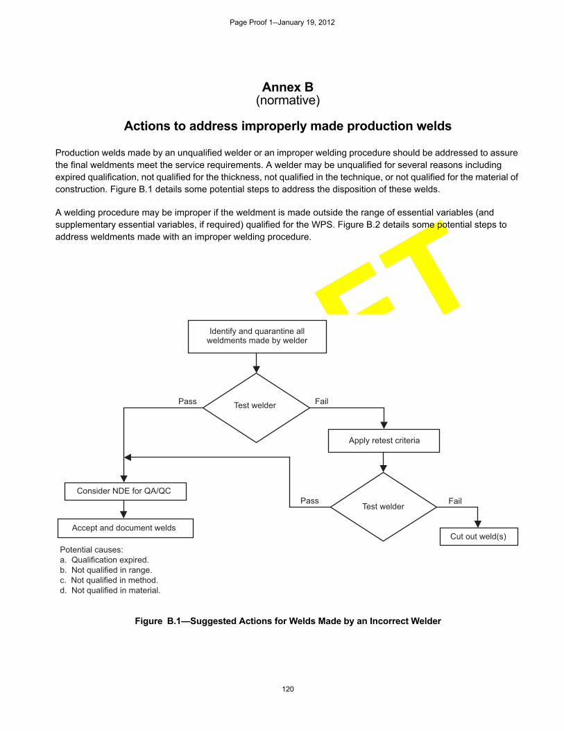
DRAFT
120
Annex B(normative)
Actions to address improperly made production welds
Production welds made by an unqualified welder or an improper welding procedure should be addressed to assure the final weldments meet the service requirements. A welder may be unqualified for several reasons including expired qualification, not qualified for the thickness, not qualified in the technique, or not qualified for the material of construction. Figure B.1 details some potential steps to address the disposition of these welds.
A welding procedure may be improper if the weldment is made outside the range of essential variables (and supplementary essential variables, if required) qualified for the WPS. Figure B.2 details some potential steps to address weldments made with an improper welding procedure.
Figure B.1—Suggested Actions for Welds Made by an Incorrect Welder
Identify and quarantine allweldments made by welder
Apply retest criteria
Cut out weld(s)Accept and document welds
Consider NDE for QA/QCPass
Pass
Fail
FailTest welder
Test welder
Potential causes:a. Qualification expired.b. Not qualified in range.c. Not qualified in method.d. Not qualified in material.
Page Proof 1--January 19, 2012
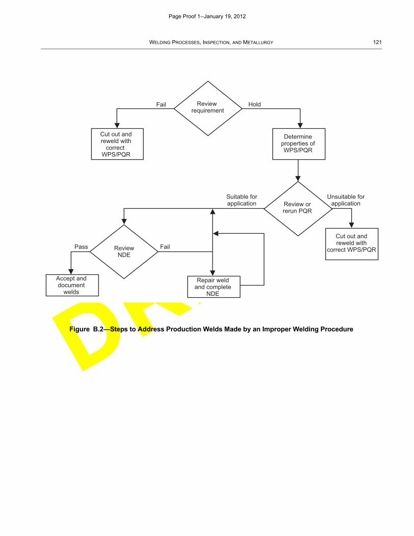
DRAFT
WELDING PROCESSES, INSPECTION, AND METALLURGY 121
Figure B.2—Steps to Address Production Welds Made by an Improper Welding Procedure
Review requirement
Review orrerun PQR
Cut out andreweld with
correct WPS/PQR
Determineproperties ofWPS/PQR
Accept anddocument
welds
Repair weldand complete
NDE
ReviewNDE
Fail Hold
Pass Fail
Suitable forapplication
Unsuitable forapplication
Cut out andreweld with
correct WPS/PQR
Page Proof 1--January 19, 2012
DRAFT
122
Annex C(informative)
Welding Procedure Review
C.1 General
This Annex presents a sample checklist prepared by a mythical company named Company Inc. to evaluate a WPSand PQR for a SMAW process. There is no ASME code requirement for a checklist; however, code users andreviewers must be certain that every variable as specified in paragraph QW-250 of ASME Section IX is addressed.
The checklist presented in this Annex is representative of other lists available in the CASTI “Guidebook to ASMESection IX—Welding Qualifications.” A narrative discussing each variable, potential problem, and where theprocedure supports the application and each other is included.
C.2 Example of Using a Checklist to Review a WPS & PQR
Figure C.1 is a sample WPS #CS-1 and Figure C.2 is a sample PQR #CS-1 prepared by a mythical company, named:Company Inc. Figures C.1 and C.2 are samples that contain typical errors in the documentation. Figure C.1 has beenprepared to help the reviewer understand how the checklists in this Annex may be used. There is no Coderequirement for a checklist. However, Code users and reviewers must make certain that every variable as specified inQW-250, by process is addressed. One method is to use the QW-250 list of variables for the process. This method isflawed in that the supplementary essential variables may distract the Code user and/or the reviewer and there areother Code requirements which are not on the QW-250 lists.
Figure C.3 is a sample checklist, which has been prepared to demonstrate how a reviewer can use the checklists inthis chapter to evaluate the Company Inc. WPS CS-1 and PQR CS-1. The following text will identify a marker, anumber in a circle such as which may be found on the sample WPS CS-1 (Figure C.1), on the sample PQR(Figure C.2), and again on the sample SMAW Checklist (Figure C.4) for Company Inc. The circled number is thendescribed in C.4 to explain each of these entries. This circled marker number may occur in more than one place, asnecessary, to locate where a given variable or entry may be found. Each reviewer may use these checklists in anymanner to suit their needs.
C.3 Checklist for WPS and PQR
Figure C.3 is a detailed checklist to document that the WPS and PQR have complied with all of the requirements ofSection IX and the applicable Construction Code. This checklist may be used by the Code user, the AuthorizedInspector, the review team, or any interested party.
The checklist provides a convenience and may be used or revised in any manner that helps the reviewer. Or thechecklist may not be required at all. You may have noticed that commercial airline pilots go through a checklist prior toevery flight. It is no less important to use a checklist when reviewing documents intended for pressure containingitems. The authors have found that using a checklist has helped where some details might otherwise be missed.Code review team members have reported that checklists are invaluable for their audits and reviews.
Figure C.3 is derived from the actual list of variables required for the SMAW process in paragraph QW-253 of SectionIX. The checklist has been prepared for welding applications where notch-toughness is not a requirement of theconstruction code and therefore the supplementary essential variables are not required, and are not listed on thischecklist. These checklists may be used when notch toughness applications are a requirement of the constructioncode by adding the supplementary essential variables from QW-253 for the applicable process.
Each checklist has three additional columns: WPS, PQR, and QUAL.
Page Proof 1--January 19, 2012
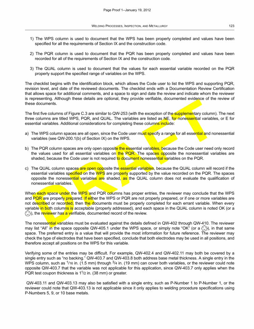
DRAFT
WELDING PROCESSES, INSPECTION, AND METALLURGY 123
1) The WPS column is used to document that the WPS has been properly completed and values have beenspecified for all the requirements of Section IX and the construction code.
2) The PQR column is used to document that the PQR has been properly completed and values have beenrecorded for all of the requirements of Section IX and the construction code.
3) The QUAL column is used to document that the values for each essential variable recorded on the PQRproperly support the specified range of variables on the WPS.
The checklist begins with the identification block, which allows the Code user to list the WPS and supporting PQR,revision level, and date of the reviewed documents. The checklist ends with a Documentation Review Certificationthat allows space for additional comments, and a space to sign and date the review and indicate whom the revieweris representing. Although these details are optional, they provide verifiable, documented evidence of the review ofthese documents.
The first five columns of Figure C.3 are similar to QW-253 (with the exception of the supplementary column). The nextthree columns are titled WPS, PQR, and QUAL. The variables are listed as NE, for nonessential variables, or E foressential variables. Additional considerations for completing these columns include:
a) The WPS column spaces are all open, since the Code user must specify a range for all essential and nonessentialvariables (see QW-200.1(b) of Section IX) on the WPS.
b) The PQR column spaces are only open opposite the essential variables, because the Code user need only recordthe values used for all essential variables on the PQR. The spaces opposite the nonessential variables areshaded, because the Code user is not required to document nonessential variables on the PQR.
c) The QUAL column spaces are open opposite the essential variables, because the QUAL column will record if theessential variables specified on the WPS are properly supported by the value recorded on the PQR. The spacesopposite the nonessential variables are shaded, as the QUAL column does not evaluate the qualification ofnonessential variables.
When each space under the WPS and PQR columns has proper entries, the reviewer may conclude that the WPSand PQR are properly prepared. If either the WPS or PQR are not properly prepared, or if one or more variables arenot described or recorded, then the documents must be properly completed for each errant variable. When everyvariable in both columns is acceptable (properly addressed), and each space in the QUAL column is noted OK (or a
), the reviewer has a verifiable, documented record of the review.
The nonessential variables must be evaluated against the details defined in QW-402 through QW-410. The reviewermay list “All” in the space opposite QW-405.1 under the WPS space, or simply note “OK” (or a ), in that samespace. The preferred entry is a value that will provide the most information for future reference. The reviewer maycheck the type of electrodes that have been specified, conclude that both electrodes may be used in all positions, andtherefore accept all positions on the WPS for this variable.
Verifying some of the entries may be difficult. For example, QW-402.4 and QW-402.11 may both be covered by asingle entry such as “no backing.” QW-403.7 and QW-403.8 both address base metal thickness. A single entry in theWPS column, such as 1/16 in. (1.5 mm) through 3/4 in. (19 mm) can cover both variables, or the reviewer could noteopposite QW-403.7 that the variable was not applicable for this application, since QW-403.7 only applies when thePQR test coupon thickness is 11/2 in. (38 mm) or greater.
QW-403.11 and QW-403.13 may also be satisfied with a single entry, such as P-Number 1 to P-Number 1, or thereviewer could note that QW-403.13 is not applicable since it only applies to welding procedure specifications usingP-Numbers 5, 9, or 10 base metals.
Page Proof 1--January 19, 2012
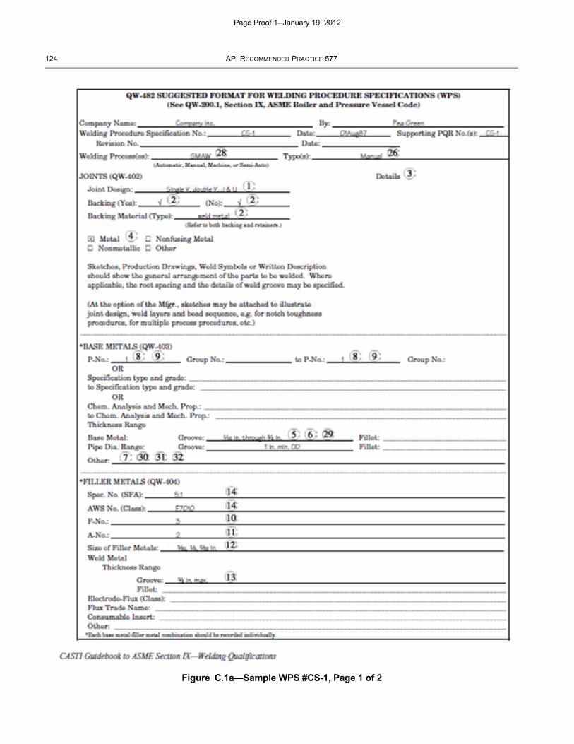
DRAFT
124 API RECOMMENDED PRACTICE 577
Figure C.1a—Sample WPS #CS-1, Page 1 of 2
Page Proof 1--January 19, 2012
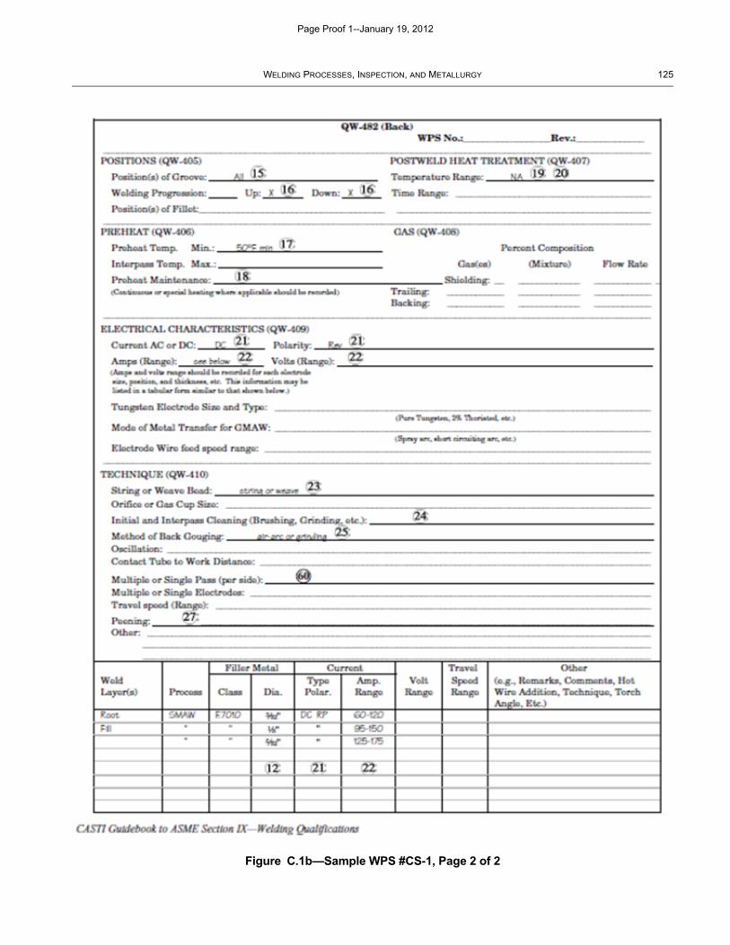
DRAFT
WELDING PROCESSES, INSPECTION, AND METALLURGY 125
Figure C.1b—Sample WPS #CS-1, Page 2 of 2
Page Proof 1--January 19, 2012
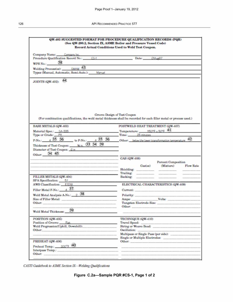
DRAFT
126 API RECOMMENDED PRACTICE 577
Figure C.2a—Sample PQR #CS-1, Page 1 of 2
Page Proof 1--January 19, 2012
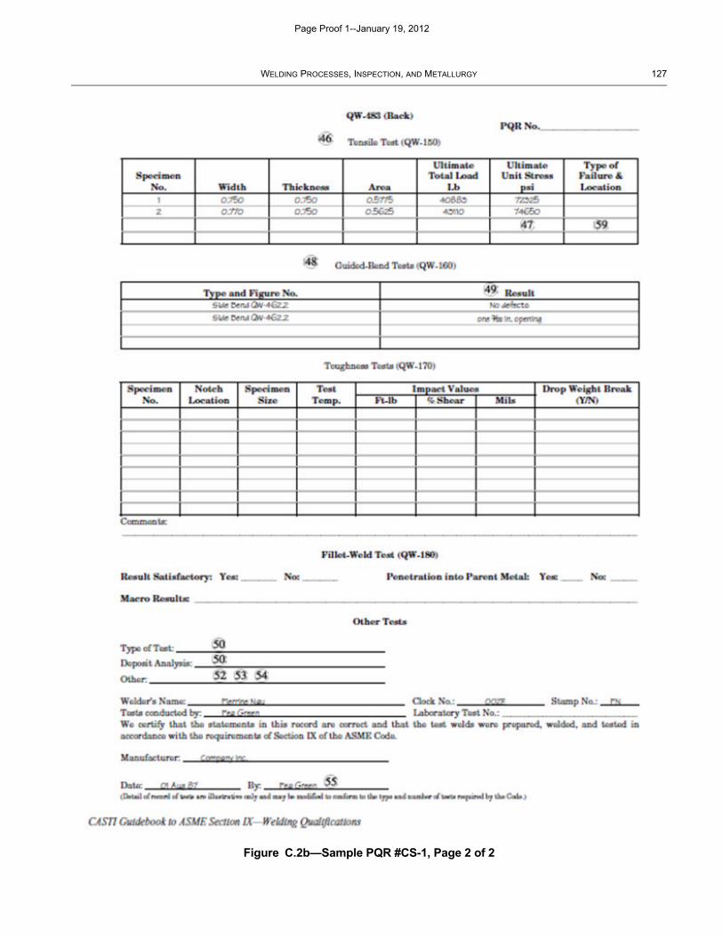
DRAFT
WELDING PROCESSES, INSPECTION, AND METALLURGY 127
Figure C.2b—Sample PQR #CS-1, Page 2 of 2
Page Proof 1--January 19, 2012
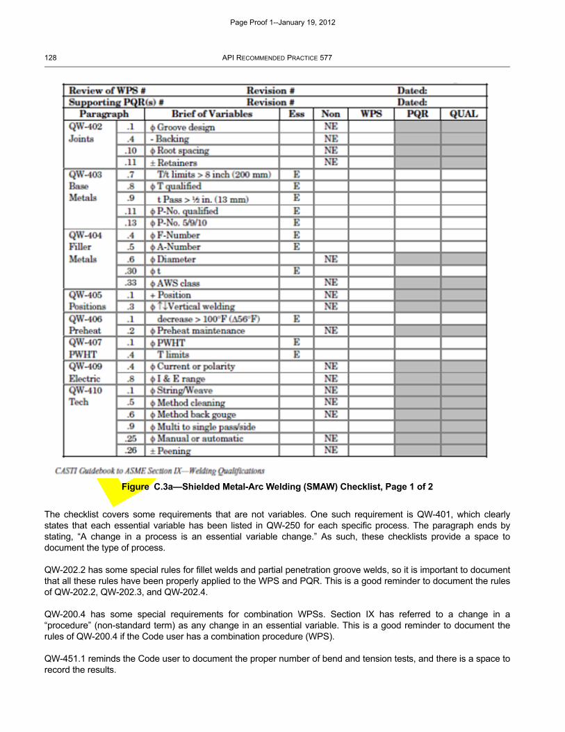
DRAFT
128 API RECOMMENDED PRACTICE 577
The checklist covers some requirements that are not variables. One such requirement is QW-401, which clearlystates that each essential variable has been listed in QW-250 for each specific process. The paragraph ends bystating, “A change in a process is an essential variable change.” As such, these checklists provide a space todocument the type of process.
QW-202.2 has some special rules for fillet welds and partial penetration groove welds, so it is important to documentthat all these rules have been properly applied to the WPS and PQR. This is a good reminder to document the rulesof QW-202.2, QW-202.3, and QW-202.4.
QW-200.4 has some special requirements for combination WPSs. Section IX has referred to a change in a“procedure” (non-standard term) as any change in an essential variable. This is a good reminder to document therules of QW-200.4 if the Code user has a combination procedure (WPS).
QW-451.1 reminds the Code user to document the proper number of bend and tension tests, and there is a space torecord the results.
Figure C.3a—Shielded Metal-Arc Welding (SMAW) Checklist, Page 1 of 2
Page Proof 1--January 19, 2012
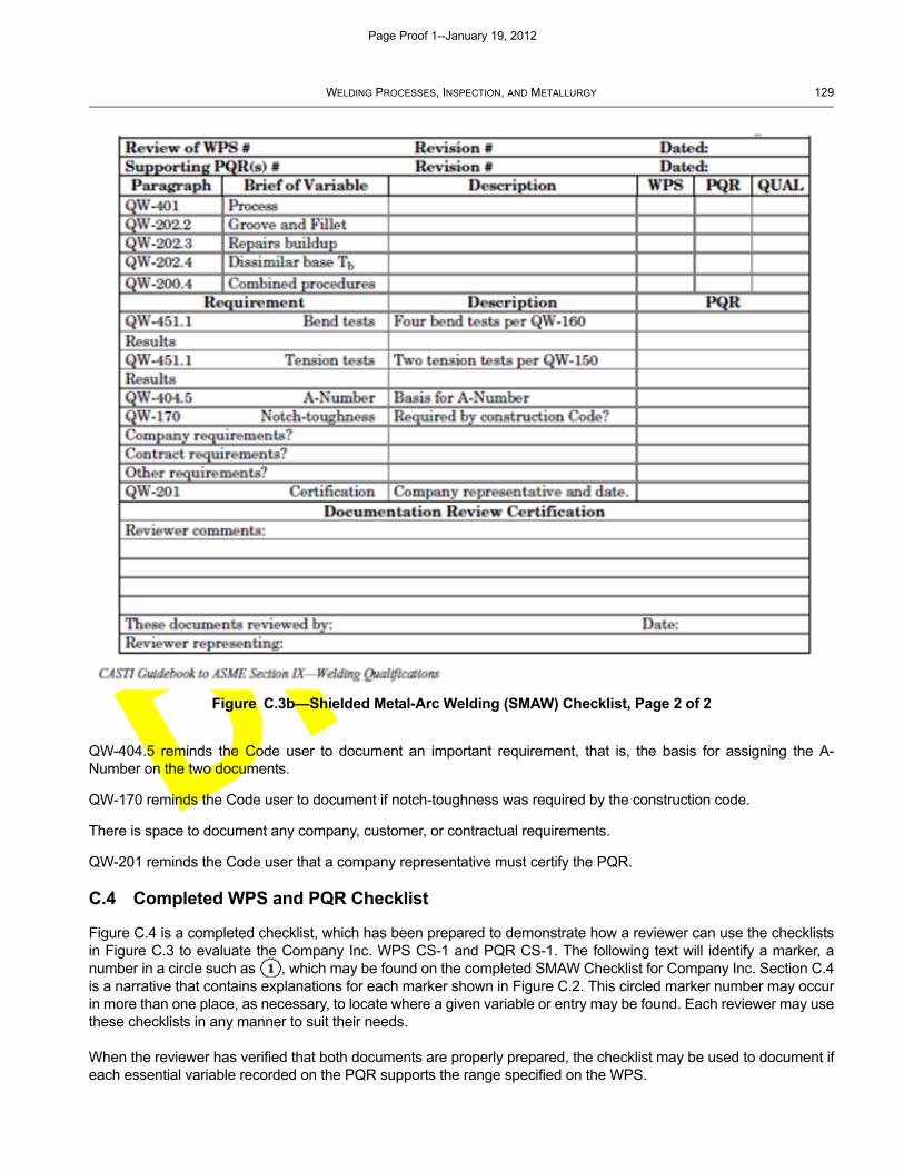
DRAFT
WELDING PROCESSES, INSPECTION, AND METALLURGY 129
QW-404.5 reminds the Code user to document an important requirement, that is, the basis for assigning the A-Number on the two documents.
QW-170 reminds the Code user to document if notch-toughness was required by the construction code.
There is space to document any company, customer, or contractual requirements.
QW-201 reminds the Code user that a company representative must certify the PQR.
C.4 Completed WPS and PQR Checklist
Figure C.4 is a completed checklist, which has been prepared to demonstrate how a reviewer can use the checklistsin Figure C.3 to evaluate the Company Inc. WPS CS-1 and PQR CS-1. The following text will identify a marker, anumber in a circle such as , which may be found on the completed SMAW Checklist for Company Inc. Section C.4is a narrative that contains explanations for each marker shown in Figure C.2. This circled marker number may occurin more than one place, as necessary, to locate where a given variable or entry may be found. Each reviewer may usethese checklists in any manner to suit their needs.
When the reviewer has verified that both documents are properly prepared, the checklist may be used to document ifeach essential variable recorded on the PQR supports the range specified on the WPS.
Figure C.3b—Shielded Metal-Arc Welding (SMAW) Checklist, Page 2 of 2
Page Proof 1--January 19, 2012
DRAFT
130 API RECOMMENDED PRACTICE 577
Figure C.1 (WPS CS-1) and Figure C.2 (PQR CS-1) are sample forms QW-482 and QW-483 respectively found inASME Section IX, non-mandatory Annex B. These forms are typical of limited information, typed into the properspace on the forms and are intended to provide examples typical of the documentation reviewers are likely toencounter.
A Code user may also review the WPS CS-1 or PQR CS-1 for a specific entry, for example, PWHT on WPS CS-1.The Code user would find PWHT on WPS CS-1 (page 2) and markers , at that entry. The Code user may thenfind and on the checklist (Figure C.4) under the WPS column and find “NA ”, indicating that the entry onWPS CS-1, at the PWHT box, which was “NA,” may not be an appropriate entry as indicated by the “ .” The Codeuser may then look for the markers , in C.5 to review the explanation of how to handle that specific entry. Thismay help the Code user who may only need a few pointers in a specific area. This exercise is not intended, however,to encourage the Code user to simply fill in the forms.
When the full checklist (Figure C.4) uses all the markers through , the reviewer may discover something aboutthe welding documentation. But equally important, the reviewer may see many blank areas on the WPS or PQR thathave not been addressed. If it is not on the checklist, the variable or entry may apply to another process orapplication. For example, there are no electrical nor technique variables (QW-409 and QW-410, respectively) listedon the PQR. Did the checklist miss these variables? No, there are no essential variables for the SMAW process ineither the QW-409 or QW-410 variables. But the sample forms in Section IX, Nonmandatory Annex B have spaces forall variables for four processes (specifically SMAW, GMAW, GTAW and SAW), which will result in blank spaces evenwhen all the variables for a specific process have been addressed. The checklist can be used to assure the reviewerthat the documentation under review has had every required variable addressed.
C.5 Checklist Narrative
C.5.1 General
A reviewer may start with the identification block at the top of both pages of Figure C.4 (completed SMAW checklist)to provide a record of the exact documentation being reviewed. A review of the values specified or recorded at eachmarker is discussed below.
The following notes are referenced to the marker (bracketed) numbers on the sample documentation of Figure C.1and Figure C.2. These same marker numbers are referenced on the sample checklist for convenience in locatingeach area where the apparent non-conformity appeared in the WPS and PQR.
C.5.2 WPS Audit Checklist
On WPS CS-1 (Figure C.1), Company Inc. listed “Single V, double V, J & U” grooves to meet the requirements ofQW-402.1. In Figure C.4, the reviewer listed V, X, J, and U as a key to what was on the WPS. QW-402.1 deals withtype of joint and, in the reviewer’s opinion, this entry addressed the groove design as required by QW-402.1. Thereviewer also believed the entry was proper and adequate. The reviewer then affixed a , indicating that an entryhad been made which addressed QW-402.1, and that the entry was do-able, and conformed to the requirements ofthe Code.
The subject of variable QW-402.4 is backing. The WPS specified “Yes and No,” which the reviewer accepted asaddressing QW-402.4. The reviewer therefore noted “yes and no” in the WPS column and a , indicating thevariable had been addressed, and the entry was acceptable. The Code user specified, “weld metal” as the backingmaterial (type). This is not a required entry, as the E6010 is obviously the backing for the subsequent E7018 layers.But it is always acceptable, and often prudent to add information beyond that required by the Code.
The reviewer could not find an entry that addressed QW-402.10, so therefore noted “not specified” in the WPScolumn and a , indicating the WPS is not complete. A range of root spacing must be specified on the WPS in orderto properly complete the WPS.
Page Proof 1--January 19, 2012
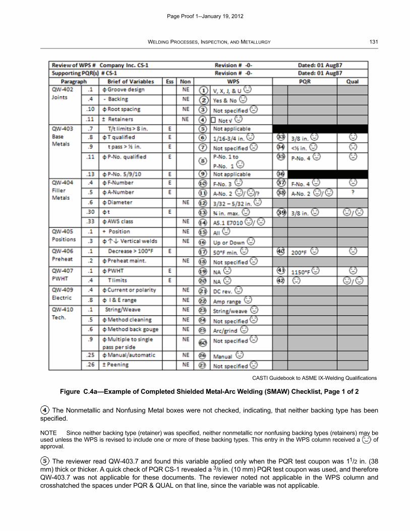
DRAFT
WELDING PROCESSES, INSPECTION, AND METALLURGY 131
The Nonmetallic and Nonfusing Metal boxes were not checked, indicating, that neither backing type has beenspecified.
NOTE Since neither backing type (retainer) was specified, neither nonmetallic nor nonfusing backing types (retainers) may beused unless the WPS is revised to include one or more of these backing types. This entry in the WPS column received a ofapproval.
The reviewer read QW-403.7 and found this variable applied only when the PQR test coupon was 11/2 in. (38mm) thick or thicker. A quick check of PQR CS-1 revealed a 3/8 in. (10 mm) PQR test coupon was used, and thereforeQW-403.7 was not applicable for these documents. The reviewer noted not applicable in the WPS column andcrosshatched the spaces under PQR & QUAL on that line, since the variable was not applicable.
Figure C.4a—Example of Completed Shielded Metal-Arc Welding (SMAW) Checklist, Page 1 of 2
CASTI Guidebook to ASME IX-Welding Qualifications
Page Proof 1--January 19, 2012

DRAFT
132 API RECOMMENDED PRACTICE 577
Figure C.4b—Example of Completed Shielded Metal-Arc Welding (SMAW) Checklist, Page 2 of 2
CASTI Guidebook to ASME IX-Welding Qualifications
Page Proof 1--January 19, 2012
DRAFT
WELDING PROCESSES, INSPECTION, AND METALLURGY 133
The reviewer noted 1/16 in. to 3/4 in. (1.5 mm to 19 mm) in the WPS column and a of approval.
The reviewer noted the thickness of each pass was “not specified .” QW-403.9 must be specified to bring WPSCS-1 into conformance with Section IX.
NOTE The reviewer should continue through each variable on the list, regardless if it is an essential or a nonessential variable,simply reviewing the subject of each variable and making certain an appropriate value for each variable was recorded on the WPS.It will be after the WPS and the PQR are both validated as complete, that the PQR will then be evaluated to determine if the valuesspecified on the WPS are supported by the values recorded on the PQR.
P-No. 1 to P-No. 1. This is an acceptable entry for the P-Number.
Not applicable. Marker indicates this WPS covers P-No. 1 and, therefore, QW-403.13, which only deals withP-Numbers 5, 9, and 10, is not applicable. The reviewer so noted “Not applicable” in the WPS column andcrosshatched the spaces under PQR & QUAL on that line.
F-Number 3. This is an acceptable entry for the F-Number.
A-Number 2 / . The Code user specified an A-Number 2 analysis. This entry gets a , because the Codeuser specified an A-Number analysis on the WPS, which meets the requirements of QW-404.5. The ,however, is caused by the fact that the reviewer cannot assess the A-Number of the E7010, since there is no suchAWS classification as detailed in marker . Without a classification, and with no other basis for the A-Numberdocumented, it is not possible to establish an A-Number 2 analysis.
3/32 in. to 5/32 in. (2.5 mm to 4 mm) . This is an acceptable entry for the filler metal diameters.
3/4 in. (19 mm) max. . This is an acceptable entry for the maximum weld metal thickness.
A5.1 E7010 / . The WPS specified an ASME SFA-5.1 specification, AWS E7010 classification, whichmeets the requirement of QW-404.33 for specifying the electrode classification.
NOTE The entry at , however, has two errors in that ASME SFA-5.1 does not have an E7010 classification. ASME SFA-5.5does cover the E70XX class of filler metals, but in this example, the E7010 is not an AWS classification without the full mandatoryclassification designator of -A1. The proper description is AWS Specification A5.5, AWS Classification E7010-A1.
All . This is an acceptable entry, indicating the WPS is acceptable for “all” positions.
Up and down were both checked . This is an acceptable entry, indicating the WPS is acceptable for both theupward and downward progressions when welding in the vertical positions.
50 °F (10 °C) minimum . This is an acceptable entry for the minimum preheat.
Not Specified .
and NA . There are times when NA is appropriate, as in markers and . But there are times when NAis not acceptable. In the instance of QW-407.1, an essential variable, the Code requires the WPS to specify which ofthe conditions of PWHT are acceptable for use with the WPS. To indicate NA for an essential variable is a red flag forinspection authorities. Most of the time the Code user intends the NA to indicate that the WPS is not qualified for usewith a PWHT applied. When a Code user has used NA on a series of WPSs intending it to mean “Not Applied” or“none applied,” the Code user may add a note indicating that when NA is noted in the PWHT space, it is intended tomean “Not Applied.” This may be a better choice than revising a series of WPSs and PQRs.
DC reverse . This is an acceptable entry for the type of current (DC), and polarity (reverse) used.
Page Proof 1--January 19, 2012
DRAFT
134 API RECOMMENDED PRACTICE 577
An amperage range is specified in the WPS for each electrode diameter. Code user’s may specify a largerange of amperage to cover a large number of filler metal diameters. An Inspection Authority may ask the Code userto demonstrate the full range of amperage listed on the WPS for the smallest filler metal diameter specified. Thisdemonstration may require a revision to the amperage range for each filler metal size.
String/Weave . It is acceptable for normal applications to specify either string bead or weave bead or both.
Not specified . In addition to Section IX, ASME Section VIII has rules for cleaning (UW-32). What better waythan to specify the construction code rules on the WPS.
Air-arc and/or grind . It is acceptable for normal applications to allow either, or both.
Not specified . QW-410.9 was originally assigned as a nonessential variable then was removed for a period oftime. The 2001 Edition of Section IX reassigned QW-410.9 as a nonessential variable. The checklist has added aspace to verify that this variable has been addressed on the WPS. That is why the numbering system is out of order.
NOTE 1 This example of a nonessential variable being removed from Section IX, and then returned, is a strong reason why aCode user should review all changes to Section IX as they are published. We strongly recommend that all documentation beupdated to meet all changes to Section IX. It is easy to say, “Changes are not required to be amended as noted in QW-100.3.”However, future problems may well be mitigated when these documents are amended to meet new requirements as they arepublished.
NOTE 2 QW-410.9 was also added as a supplementary essential variable.
Manual . Specified on page 1 of WPS CS-1.
Not specified . Section IX requires the addition or deletion of peening to be specified on the WPS.
NOTE In addition to Section IX, ASME Section VIII has rules for peening (UW-39) which has some technical considerations,including PWHT considerations. Section VIII, UW-39, does not permit peening on the first or last pass unless the weld will besubjected to a PWHT. This sample WPS should restrict peening on the first or last pass, if the welding application is to be used ona Section VIII Code Stamped item.
√ The √ in the WPS column, page 2 of 2 indicates that a welding process was specified, as required by QW-401, which states, in part, that a change in process is an essential variable. The reviewer also inserted a ,indicating that the process specified was proper.
√ In the WPS column, page 2 of 2 (QW-403, page 1 of WPS #CS-1) indicates the rules of QW-202.2(a) havebeen met in that the WPS specified groove welds.
NOTE The WPS did not indicate anything for fillet welds. A groove welded PQR supports all fillet welds, but the WPS mustspecify it is applicable for fillet welds.
QW-202.3 allows repairs and buildup, but there was no special mention of such on the WPS. This does not meanthat the WPS may not be used for repairs and buildup, but rather that no special provisions were made for QW-202.3;hence, the crosshatch in the WPS column indicating no comment.
QW-202.4 has special allowances for dissimilar base metal thicknesses, but this WPS is not eligible for any ofthose special provisions; hence, the crosshatch indicating not applicable in the WPS column.
QW-200.4 has special rules for combination of procedures. In the description column, the reviewer noted that thisWPS could take advantage of QW-200.4(a), but not QW-200.4(b).
The reviewer notes on the bottom of page 2 of 2 of the checklist that there are several items that must be resolvedbefore WPS CS-1 may be accepted. For the purpose of this guide, however, the reviewer will now begin the review ofPQR CS-1.
Page Proof 1--January 19, 2012
DRAFT
WELDING PROCESSES, INSPECTION, AND METALLURGY 135
C.5.3 PQR Audit Checklist
3/8 in. (10 mm) . Indicates the thickness of the base metal test coupon Tc has been recorded on PQR CS-1(Figure C-2). It is tempting at this point to begin comparing the PQR to the WPS, but this is not the time. The reviewershould verify that the PQR has properly addressed each essential variable, before determining if some parts of thePQR support some parts of the WPS. In the end, there is so much interaction between the variables, that bothdocuments must be properly and completely prepared before any comparison may be meaningfully conducted.
< 1/2 in. (13 mm) . QW-403.9 requires the PQR to note if any single passes were greater than 1/2 in. (13 mm)in weld metal thickness. When the PQR test coupon is only 3/8 in. (10 mm), it is obvious that no single pass wasgreater than 1/2 in. (13 mm), thus the < 1/2 in. (13 mm) gets a . There is no need to note specifically the variableand that no passes > 1/2 in. (13 mm), until the PQR test coupon exceeds 1/2 in. (13 mm).
P-Number 4 . ASME SA-335, Grade P11 has been verified as a P-Number 4 base metal (QW/QB-422) and P-Number 4 was recorded per QW-403.11. The PQR test coupon (ASME SA-335, Grade P 11) is a P-Number 4,despite the confusing Grade P11 on the end of the specification. The ASTM A 335 Grade P11 designation identifiesthe base metal as a 11/4Cr-1/2Mo base metal, which has been assigned to the ASME Section IX, P-Number 4 basemetal grouping.
Caution—It is easy to confuse an ASTM Grade PXX number with the ASME P-Numbers. This example shouldremind the Code user to use full descriptions of all materials carefully.
Not Applicable. (QW-403.13 covers P-Numbers 5, 9, and 10 only). The reviewer crosshatched the spaces underPQR & QUAL on that line, since the variable was not applicable.
F-Number 4 . This is an acceptable entry for the filler metal F-Number used.
A-Number 2 / . The is because an A-Number was recorded. The is because the A-Number 2 is anerror. The PQR listed an E7018 filler metal. Based on QW-442, in order to have an A-Number 2 analysis, theelectrode must have a deposit with 0.4 % to 0.65 % Mo. In ASME SFA-5.1, AWS A5.1 E7018 must be produced witha guaranteed analysis of 0.30 % Mo. maximum, therefore, it is not possible for an E7018 classified filler metal to havean A-Number 2 analysis.
3/8 in. (10 mm) . This is an acceptable method of recording the thickness of the test coupon for a singleprocess PQR.
NOTE Filler Metals (QW-404) has a space specifically for weld metal thickness.
200 °F (95 °C) . This is an acceptable method of recording the minimum preheat temperature applied on thePQR.
NOTE The WPS may specify an “increase” in preheat temperature that is much warmer than that which was recorded on thePQR. The “minimum” preheat, however, must be limited to a value not “less” than ∆100 °F (∆56 °C).
1150 °F (620 °C) ± 50 °F (∆28 °C) . This is an acceptable method of specifying the actual PWHT temperatureused. QW-407.1(a)(2) specifies the condition; “PWHT below the lower transformation temperature.” This conditioncan be determined from the actual recorded condition of 1150 °F (620 °C) ± 50 °F (∆28 °C). The Code user must gobeyond Section IX to evaluate the PWHT conditions of QW-407. There is no guidance in Section IX for determiningthese PWHT conditions
The PQR indicated the PWHT was conducted; “below the lower transformation temperature.” This gives thereviewer confidence that QW-407.4 has been addressed, since QW-407.4 only applies to applications when a PWHThas been applied; “above the upper transformation temperature.” Listing one of the actual PWHT conditions of QW-407.1 is an excellent method of addressing the PWHT essential variables.
Page Proof 1--January 19, 2012
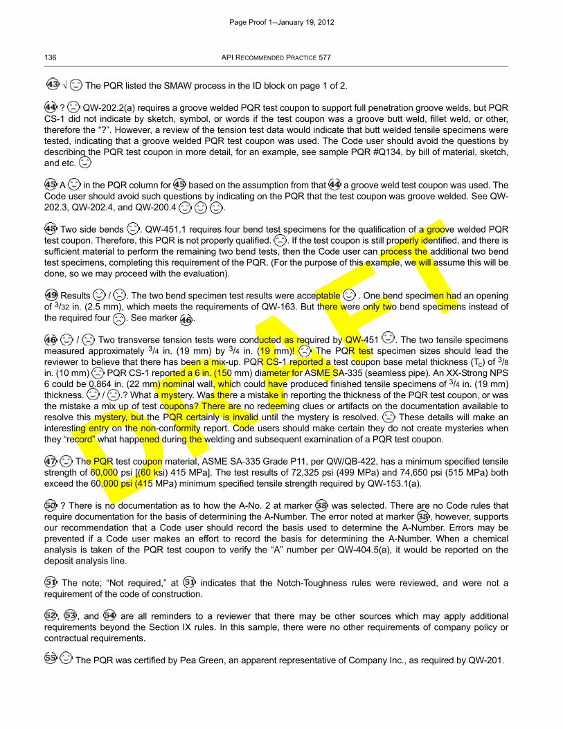
DRAFT
136 API RECOMMENDED PRACTICE 577
√ The PQR listed the SMAW process in the ID block on page 1 of 2.
? QW-202.2(a) requires a groove welded PQR test coupon to support full penetration groove welds, but PQRCS-1 did not indicate by sketch, symbol, or words if the test coupon was a groove butt weld, fillet weld, or other,therefore the “?”. However, a review of the tension test data would indicate that butt welded tensile specimens weretested, indicating that a groove welded PQR test coupon was used. The Code user should avoid the questions bydescribing the PQR test coupon in more detail, for an example, see sample PQR #Q134, by bill of material, sketch,and etc.
A in the PQR column for based on the assumption from that a groove weld test coupon was used. TheCode user should avoid such questions by indicating on the PQR that the test coupon was groove welded. See QW-202.3, QW-202.4, and QW-200.4 .
Two side bends . QW-451.1 requires four bend test specimens for the qualification of a groove welded PQRtest coupon. Therefore, this PQR is not properly qualified. . If the test coupon is still properly identified, and there issufficient material to perform the remaining two bend tests, then the Code user can process the additional two bendtest specimens, completing this requirement of the PQR. (For the purpose of this example, we will assume this will bedone, so we may proceed with the evaluation).
Results / . The two bend specimen test results were acceptable . One bend specimen had an openingof 3/32 in. (2.5 mm), which meets the requirements of QW-163. But there were only two bend specimens instead ofthe required four . See marker .
/ Two transverse tension tests were conducted as required by QW-451 . The two tensile specimensmeasured approximately 3/4 in. (19 mm) by 3/4 in. (19 mm)! The PQR test specimen sizes should lead thereviewer to believe that there has been a mix-up. PQR CS-1 reported a test coupon base metal thickness (Tc) of 3/8in. (10 mm) PQR CS-1 reported a 6 in. (150 mm) diameter for ASME SA-335 (seamless pipe). An XX-Strong NPS6 could be 0.864 in. (22 mm) nominal wall, which could have produced finished tensile specimens of 3/4 in. (19 mm)thickness. / .? What a mystery. Was there a mistake in reporting the thickness of the PQR test coupon, or wasthe mistake a mix up of test coupons? There are no redeeming clues or artifacts on the documentation available toresolve this mystery, but the PQR certainly is invalid until the mystery is resolved. These details will make aninteresting entry on the non-conformity report. Code users should make certain they do not create mysteries whenthey “record” what happened during the welding and subsequent examination of a PQR test coupon.
The PQR test coupon material, ASME SA-335 Grade P11, per QW/QB-422, has a minimum specified tensilestrength of 60,000 psi [(60 ksi) 415 MPa]. The test results of 72,325 psi (499 MPa) and 74,650 psi (515 MPa) bothexceed the 60,000 psi (415 MPa) minimum specified tensile strength required by QW-153.1(a).
? There is no documentation as to how the A-No. 2 at marker was selected. There are no Code rules thatrequire documentation for the basis of determining the A-Number. The error noted at marker , however, supportsour recommendation that a Code user should record the basis used to determine the A-Number. Errors may beprevented if a Code user makes an effort to record the basis for determining the A-Number. When a chemicalanalysis is taken of the PQR test coupon to verify the “A” number per QW-404.5(a), it would be reported on thedeposit analysis line.
The note; “Not required,” at indicates that the Notch-Toughness rules were reviewed, and were not arequirement of the code of construction.
, , and are all reminders to a reviewer that there may be other sources which may apply additionalrequirements beyond the Section IX rules. In this sample, there were no other requirements of company policy orcontractual requirements.
The PQR was certified by Pea Green, an apparent representative of Company Inc., as required by QW-201.
Page Proof 1--January 19, 2012
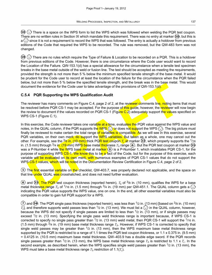
DRAFT
WELDING PROCESSES, INSPECTION, AND METALLURGY 137
There is a space on the WPS form to list the WPS which was followed when welding the PQR test coupon.There are no written rules in Section IX which mandate this requirement. There was no entry at marker , but this isa since it is not a requirement to record the WPS that was followed. The entry is actually a holdover from previouseditions of the Code that required the WPS to be recorded. The rule was removed, but the QW-483 form was notchanged.
There are no rules which require the Type of Failure & Location to be recorded on a PQR. This is a holdoverfrom previous editions of the Code. However, there is one circumstance where the Code user would want to recordthe Location of the Failure. QW-153.1(d) has a special allowance for the circumstance when a tensile test specimenbreaks in the base metal outside of the weld or fusion line. The test should be accepted as meeting the requirements,provided the strength is not more than 5 % below the minimum specified tensile strength of the base metal. It wouldbe prudent for the Code user to record at least the location of the failure for the circumstance when the PQR failedbelow, but not more than 5 % below the specified tensile strength, and the break was in the base metal. This woulddocument the evidence for the Code user to take advantage of the provisions of QW-153.1(d).
C.5.4 PQR Supporting the WPS Qualification Audit
The reviewer has many comments on Figure C.4, page 2 of 2, at the reviewer comments line, noting items that mustbe resolved before PQR CS-1 may be accepted. For the purpose of this guide, however, the reviewer will now beginthe review to document if the values recorded on PQR CS-1 (Figure C.2) adequately support the values specified onWPS CS-1 (Figure C.1).
In this exercise, the Code reviewer takes one variable at a time, evaluates the PQR value against the WPS value andnotes, in the QUAL column, if the PQR supports the WPS or does not support the WPS . The big picture mustfinally be reviewed to make certain the total range of variables is compatible. As we will see in this exercise, severalPQR variables, on their own merit, do support the WPS variables. But taken as a whole, one may cancel out theother. For example, see the 3/8 in. (10 mm) thick PQR test coupon Tc at marker , which properly supports the 1/16
in. (1.5 mm) through 3/4 in. (19 mm) WPS base metal thickness Tb range . But the PQR test coupon at marker was a P-Number 4 while the WPS base metal at marker is a P-Number 1, which invalidates PQR CS-1, for thepurpose of supporting WPS CS-1. We know this to be a fact of the Code, but for the purpose of this exercise, eachvariable will be evaluated on its own merit, with numerous examples of PQR CS-1 values that do not support theWPS CS-1 values, which will be noted in the Documentation Review Certification in Figure C.4, page 2 of 2.
The first essential variable on the checklist, QW-403.7, was properly declared not applicable, and the space onthat line under QUAL was crosshatched, and does not need further evaluation.
and . The PQR test coupon thickness (reported herein), Tc of 3/8 in. (10 mm), qualifies the WPS for a basemetal thickness range Tb of 1/16 in. (1.5 mm) through 3/4 in. (19 mm) per QW-451.1. The QUAL column gets a indicating the PQR value supports the WPS value, one on one. In the end, all other essential variables must also becompatible in order to gain full PQR support for a WPS.
and . The PQR single pass thickness (reported herein), was less than 1/2 in. (13 mm) [based on 3/8 in. (10 mm)Tc], and therefore supports weld passes less than 1/2 in. (13 mm). We must list a in the QUAL column, however,because the WPS did not specify if single passes are limited to less than 1/2 in. (13 mm), or if single passes mayexceed 1/2 in. (13 mm). Specifying the single pass weld thickness range is important because, if WPS CS-1 iscorrected to specify no single pass greater than 1/2 in. (13 mm) weld metal, then PQR CS-1 will support the 1/16 in.(1.5 mm) through 3/4 in. (19 mm) base metal thickness range Tb. However, if WPS CS-1 is corrected to specify thatsingle weld passes may be greater than 1/2 in. (13 mm), then the WPS maximum base metal thickness rangesupported by the PQR is restricted to a range of 1.1 times the PQR test coupon thickness, or 1.1 x 0.375 in. (9.5 mm)= 0.4125 in. (10.5 mm) maximum base metal thickness. QW–403.9 has a double edge sword. If the PQR recordssingle passes greater than 1/2 in. (13 mm), the WPS base metal thickness range Tb is restricted to 1.1 x Tc. In thesecond example, as described herein, when the WPS specifies single weld passes greater than 1/2 in. (13 mm), theWPS must take a base metal thickness range Tb restriction of 1.1(Tc).
Page Proof 1--January 19, 2012
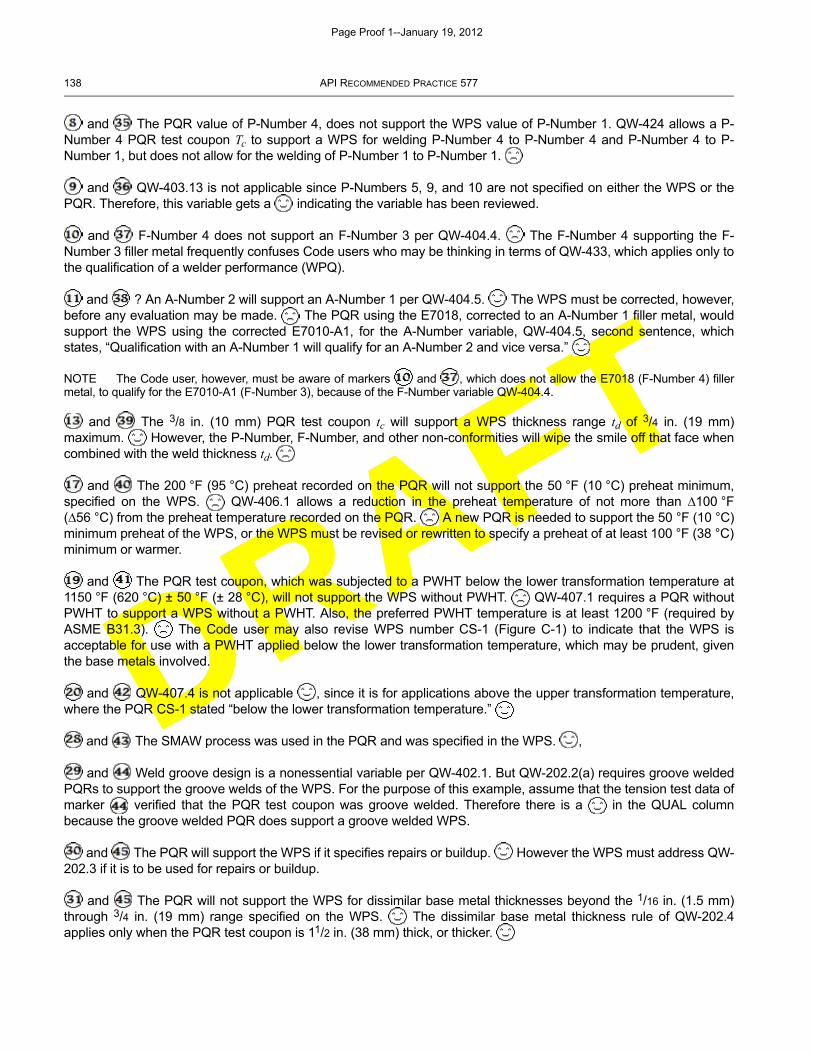
DRAFT
138 API RECOMMENDED PRACTICE 577
and The PQR value of P-Number 4, does not support the WPS value of P-Number 1. QW-424 allows a P-Number 4 PQR test coupon Tc to support a WPS for welding P-Number 4 to P-Number 4 and P-Number 4 to P-Number 1, but does not allow for the welding of P-Number 1 to P-Number 1.
and QW-403.13 is not applicable since P-Numbers 5, 9, and 10 are not specified on either the WPS or thePQR. Therefore, this variable gets a indicating the variable has been reviewed.
and F-Number 4 does not support an F-Number 3 per QW-404.4. The F-Number 4 supporting the F-Number 3 filler metal frequently confuses Code users who may be thinking in terms of QW-433, which applies only tothe qualification of a welder performance (WPQ).
and ? An A-Number 2 will support an A-Number 1 per QW-404.5. The WPS must be corrected, however,before any evaluation may be made. The PQR using the E7018, corrected to an A-Number 1 filler metal, wouldsupport the WPS using the corrected E7010-A1, for the A-Number variable, QW-404.5, second sentence, whichstates, “Qualification with an A-Number 1 will qualify for an A-Number 2 and vice versa.”
NOTE The Code user, however, must be aware of markers and , which does not allow the E7018 (F-Number 4) fillermetal, to qualify for the E7010-A1 (F-Number 3), because of the F-Number variable QW-404.4.
and The 3/8 in. (10 mm) PQR test coupon tc will support a WPS thickness range td of 3/4 in. (19 mm)maximum. However, the P-Number, F-Number, and other non-conformities will wipe the smile off that face whencombined with the weld thickness td.
and The 200 °F (95 °C) preheat recorded on the PQR will not support the 50 °F (10 °C) preheat minimum,specified on the WPS. QW-406.1 allows a reduction in the preheat temperature of not more than ∆100 °F(∆56 °C) from the preheat temperature recorded on the PQR. A new PQR is needed to support the 50 °F (10 °C)minimum preheat of the WPS, or the WPS must be revised or rewritten to specify a preheat of at least 100 °F (38 °C)minimum or warmer.
and The PQR test coupon, which was subjected to a PWHT below the lower transformation temperature at1150 °F (620 °C) ± 50 °F (± 28 °C), will not support the WPS without PWHT. QW-407.1 requires a PQR withoutPWHT to support a WPS without a PWHT. Also, the preferred PWHT temperature is at least 1200 °F (required byASME B31.3). The Code user may also revise WPS number CS-1 (Figure C-1) to indicate that the WPS isacceptable for use with a PWHT applied below the lower transformation temperature, which may be prudent, giventhe base metals involved.
and QW-407.4 is not applicable , since it is for applications above the upper transformation temperature,where the PQR CS-1 stated “below the lower transformation temperature.”
and The SMAW process was used in the PQR and was specified in the WPS. ,
and Weld groove design is a nonessential variable per QW-402.1. But QW-202.2(a) requires groove weldedPQRs to support the groove welds of the WPS. For the purpose of this example, assume that the tension test data ofmarker verified that the PQR test coupon was groove welded. Therefore there is a in the QUAL columnbecause the groove welded PQR does support a groove welded WPS.
and The PQR will support the WPS if it specifies repairs or buildup. However the WPS must address QW-202.3 if it is to be used for repairs or buildup.
and The PQR will not support the WPS for dissimilar base metal thicknesses beyond the 1/16 in. (1.5 mm)through 3/4 in. (19 mm) range specified on the WPS. The dissimilar base metal thickness rule of QW-202.4applies only when the PQR test coupon is 11/2 in. (38 mm) thick, or thicker.
Page Proof 1--January 19, 2012
DRAFT
WELDING PROCESSES, INSPECTION, AND METALLURGY 139
NOTE The QW-202.4 rule may be applied for P-Number 8 and P-Number 41 through P-Number 47 PQR test coupons 1/4 in. (6mm) thick and thicker.
and The PQR will support the WPS for combination procedure WPSs, but only within the QW-200.4(a) range. The QW-200.4(b) rule applies for carbon steel PQR test coupons 1/2 in. (13 mm) thick and thicker.
C.5.5 Documentation Review Certification
The reviewer summarized all findings in the Documentation Review Certification Block, making notes for each non-conformity found, for future reference. There are just too many interdependent complications to try to remember thedetails of each non-conformity. The reviewer listed each item that had to be resolved on the WPS and PQR, and listedthe essential variables recorded on the PQR that did not support the ranges specified on the WPS.
There were numerous blank spaces on PQR #CS-1 (Figure C.2) which were not addressed. Specifically, on page 1 of2, WPS Number, Size of Filler Metal, Electrical Characteristics (QW-409), Interpass Temperature, Technique (QW-410) and other spaces were left blank. The rules of Section IX do not require these variables to be recorded on thePQR. However, any additional details added to the PQR may prove to be an invaluable resource for future use.
The reviewer should then certify the checklist, noting every non-conformity. The final space should specify who thereviewer is representing. This could be the jurisdiction, authorized inspection agency, insurance carrier, customer,Code user or etc.
Page Proof 1--January 19, 2012
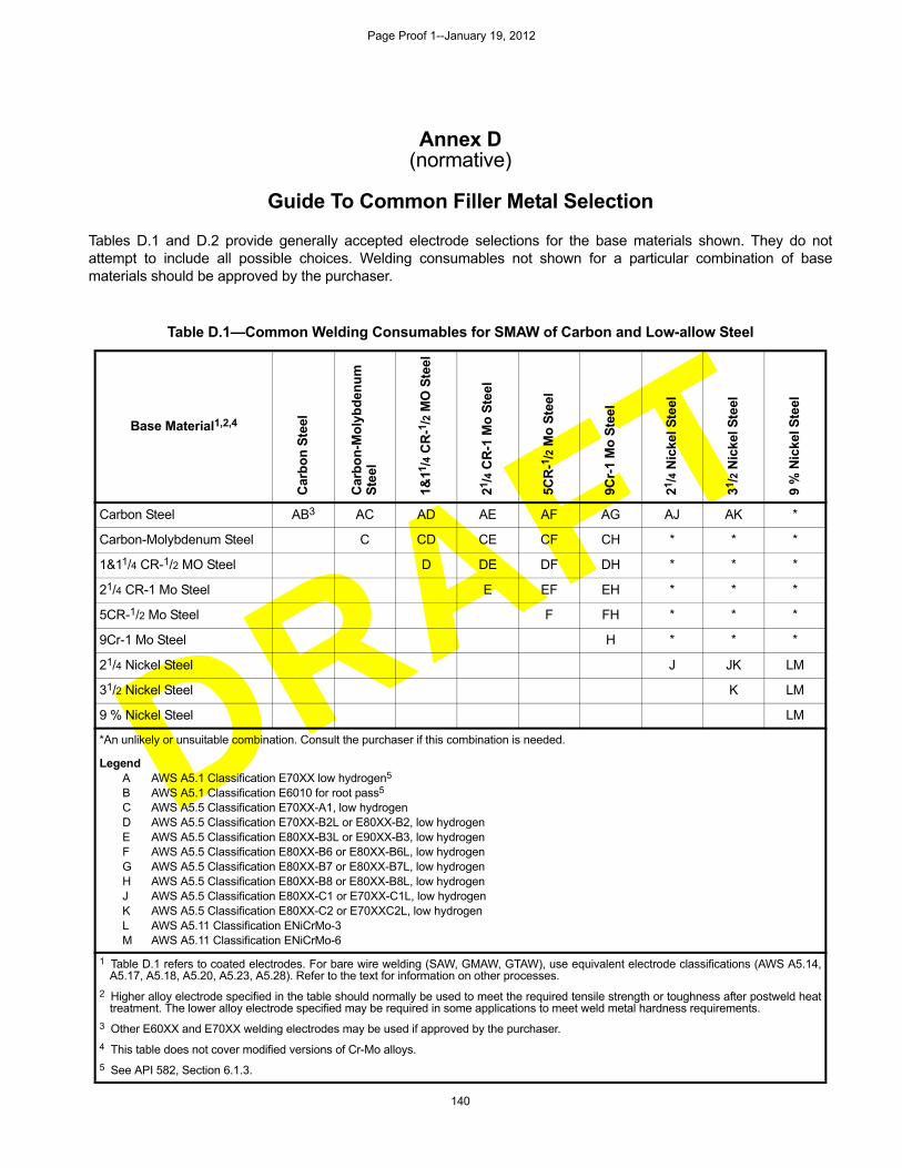
DRAFT
140
Annex D(normative)
Guide To Common Filler Metal Selection
Tables D.1 and D.2 provide generally accepted electrode selections for the base materials shown. They do notattempt to include all possible choices. Welding consumables not shown for a particular combination of basematerials should be approved by the purchaser.
Table D.1—Common Welding Consumables for SMAW of Carbon and Low-allow Steel
Base Material1,2,4
Car
bo
n S
teel
Car
bo
n-M
oly
bd
enu
m
Ste
el
1&11
/4 C
R-1
/2 M
O S
teel
21/4
CR
-1 M
o S
teel
5CR
-1/2
Mo
Ste
el
9Cr-
1 M
o S
teel
21/4
Nic
kel S
teel
31/2
Nic
kel S
teel
9%
Nic
kel S
teel
Carbon Steel AB3 AC AD AE AF AG AJ AK *
Carbon-Molybdenum Steel C CD CE CF CH * * *
1&11/4 CR-1/2 MO Steel D DE DF DH * * *
21/4 CR-1 Mo Steel E EF EH * * *
5CR-1/2 Mo Steel F FH * * *
9Cr-1 Mo Steel H * * *
21/4 Nickel Steel J JK LM
31/2 Nickel Steel K LM
9 % Nickel Steel LM
*An unlikely or unsuitable combination. Consult the purchaser if this combination is needed.
LegendA AWS A5.1 Classification E70XX low hydrogen5
B AWS A5.1 Classification E6010 for root pass5
C AWS A5.5 Classification E70XX-A1, low hydrogenD AWS A5.5 Classification E70XX-B2L or E80XX-B2, low hydrogenE AWS A5.5 Classification E80XX-B3L or E90XX-B3, low hydrogenF AWS A5.5 Classification E80XX-B6 or E80XX-B6L, low hydrogenG AWS A5.5 Classification E80XX-B7 or E80XX-B7L, low hydrogenH AWS A5.5 Classification E80XX-B8 or E80XX-B8L, low hydrogenJ AWS A5.5 Classification E80XX-C1 or E70XX-C1L, low hydrogenK AWS A5.5 Classification E80XX-C2 or E70XXC2L, low hydrogenL AWS A5.11 Classification ENiCrMo-3M AWS A5.11 Classification ENiCrMo-6
1 Table D.1 refers to coated electrodes. For bare wire welding (SAW, GMAW, GTAW), use equivalent electrode classifications (AWS A5.14,A5.17, A5.18, A5.20, A5.23, A5.28). Refer to the text for information on other processes.
2 Higher alloy electrode specified in the table should normally be used to meet the required tensile strength or toughness after postweld heattreatment. The lower alloy electrode specified may be required in some applications to meet weld metal hardness requirements.
3 Other E60XX and E70XX welding electrodes may be used if approved by the purchaser.
4 This table does not cover modified versions of Cr-Mo alloys.
5 See API 582, Section 6.1.3.
Page Proof 1--January 19, 2012
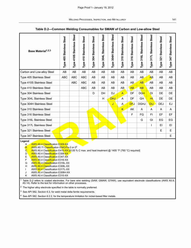
DRAFT
WELDING PROCESSES, INSPECTION, AND METALLURGY 141
Table D.2—Common Welding Consumables for SMAW of Carbon and Low-allow Steel
Base Material1,2,3
Typ
e 40
5 S
tain
less
Ste
el
Typ
e 41
0S S
tain
less
Ste
el
Typ
e 41
0 S
tain
less
Ste
el
Typ
e 30
4 S
tain
less
Ste
el
Typ
e 30
4L S
tain
less
Ste
el
Typ
e 30
4H S
tain
less
Ste
el
Typ
e 31
0 S
tain
less
Ste
el
Typ
e 31
6 S
tain
less
Ste
el
Typ
e 31
6L S
tain
less
Ste
el
Typ
e 31
7L S
tain
less
Ste
el
Typ
e 32
1 S
tain
less
Ste
el
Typ
e 34
7 S
tain
less
Ste
el
Carbon and Low-alloy Steel AB AB AB AB AB AB AB AB AB AB AB AB
Type 405 Stainless Steel ABC ABC ABC AB AB AB AB AB AB AB AB AB
Type 410S Stainless Steel ABC ABC AB AB AB AB AB AB AB AB AB
Type 410 Stainless Steel ABC AB AB AB AB AB AB AB AB AB
Type 304 Stainless Steel D DH DJ A DF DGH DI DE DE
Type 304L Stainless Steel H DHJ A DF GH HI DE DE
Type 304H Stainless Steel J A DFJ DGHJ DIJ DEJ EJ
Type 310 Stainless Steel K AK A A A A
Type 316 Stainless Steel F FG FI EF EF
Type 316L Stainless Steel G GI EG EG
Type 317L Stainless Steel I EI EI
Type 321 Stainless Steel E E
Type 347 Stainless Steel E
LegendA AWS A5.4 Classification E309-XXB AWS A5.11 Classification ENiCrFe-2 or-34
C AWS A5.4 Classification E410-XX [(0.05 % C max. and heat treatment @ 1400 °F (760 °C) required]D AWS A5.4 Classification E308-XXE AWS A5.4 Classification E347-XXF AWS A5.4 Classification E316-XXG AWS A5.4 Classification E316L-XXH AWS A5.4 Classification E308L-XXI AWS A5.4 Classification E317L-XXJ AWS A5.4 Classification E308H-XXK AWS A5.4 Classification E310-XX
1 Table D.2 refers to coated electrodes. For bare wire welding (SAW, GMAW, GTAW), use equivalent electrode classifications (AWS A5.9,A5.14). Refer to the text for information on other processes.
2 The higher alloy electrode specified in the table is normally preferred.
3 See API 582, Section 6.3, for weld metal delta ferrite requirements.
4 See API 582, Section 6.2.2, for the temperature limitation for nickel-based filler metals.
Page Proof 1--January 19, 2012
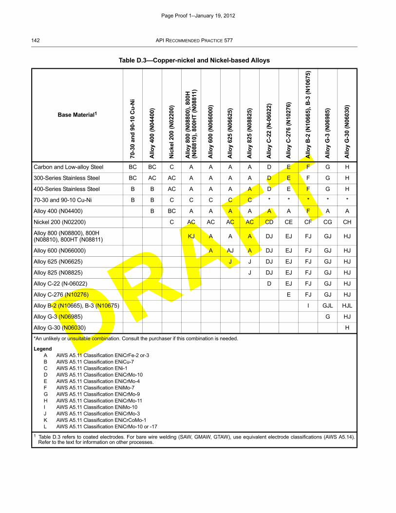
DRAFT
142 API RECOMMENDED PRACTICE 577
Table D.3—Copper-nickel and Nickel-based Alloys
Base Material1
70-3
0 an
d 9
0-10
Cu
-Ni
Allo
y 40
0 (N
0440
0)
Nic
kel 2
00 (
N02
200)
Allo
y 80
0 (N
0880
0), 8
00H
(N
0881
0), 8
00H
T (
N08
811)
Allo
y 60
0 (N
0660
00)
Allo
y 62
5 (N
0662
5)
Allo
y 82
5 (N
0882
5)
Allo
y C
-22
(N-0
6022
)
Allo
y C
-276
(N
1027
6)
Allo
y B
-2 (
N10
665)
, B-3
(N
1067
5)
Allo
y G
-3 (
N06
985)
Allo
y G
-30
(N06
030)
Carbon and Low-alloy Steel BC BC C A A A A D E F G H
300-Series Stainless Steel BC AC AC A A A A D E F G H
400-Series Stainless Steel B B AC A A A A D E F G H
70-30 and 90-10 Cu-Ni B B C C C C C * * * * *
Alloy 400 (N04400) B BC A A A A A A F A A
Nickel 200 (N02200) C AC AC AC AC CD CE CF CG CH
Alloy 800 (N08800), 800H (N08810), 800HT (N08811)
KJ A A A DJ EJ FJ GJ HJ
Alloy 600 (N066000) A AJ A DJ EJ FJ GJ HJ
Alloy 625 (N06625) J J DJ EJ FJ GJ HJ
Alloy 825 (N08825) J DJ EJ FJ GJ HJ
Alloy C-22 (N-06022) D EJ FJ GJ HJ
Alloy C-276 (N10276) E FJ GJ HJ
Alloy B-2 (N10665), B-3 (N10675) I GJL HJL
Alloy G-3 (N06985) G HJ
Alloy G-30 (N06030) H
*An unlikely or unsuitable combination. Consult the purchaser if this combination is needed.
LegendA AWS A5.11 Classification ENiCrFe-2 or-3B AWS A5.11 Classification ENiCu-7C AWS A5.11 Classification ENi-1D AWS A5.11 Classification ENiCrMo-10E AWS A5.11 Classification ENiCrMo-4F AWS A5.11 Classification ENiMo-7G AWS A5.11 Classification ENiCrMo-9H AWS A5.11 Classification ENiCrMo-11I AWS A5.11 Classification ENiMo-10J AWS A5.11 Classification ENiCrMo-3K AWS A5.11 Classification ENiCrCoMo-1L AWS A5.11 Classification ENiCrMo-10 or -17
1 Table D.3 refers to coated electrodes. For bare wire welding (SAW, GMAW, GTAW), use equivalent electrode classifications (AWS A5.14).Refer to the text for information on other processes.
Page Proof 1--January 19, 2012
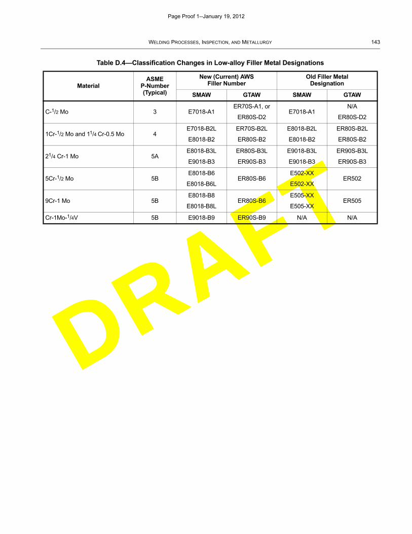
DRAFT
WELDING PROCESSES, INSPECTION, AND METALLURGY 143
Table D.4—Classification Changes in Low-alloy Filler Metal Designations
MaterialASME
P-Number(Typical)
New (Current) AWSFiller Number
Old Filler Metal Designation
SMAW GTAW SMAW GTAW
C-1/2 Mo 3 E7018-A1ER70S-A1, or
ER80S-D2E7018-A1
N/A
ER80S-D2
1Cr-1/2 Mo and 11/4 Cr-0.5 Mo 4E7018-B2L
E8018-B2
ER70S-B2L
ER80S-B2
E8018-B2L
E8018-B2
ER80S-B2L
ER80S-B2
21/4 Cr-1 Mo 5AE8018-B3L
E9018-B3
ER80S-B3L
ER90S-B3
E9018-B3L
E9018-B3
ER90S-B3L
ER90S-B3
5Cr-1/2 Mo 5BE8018-B6
E8018-B6LER80S-B6
E502-XX
E502-XXER502
9Cr-1 Mo 5BE8018-B8
E8018-B8LER80S-B6
E505-XX
E505-XXER505
Cr-1Mo-1/4V 5B E9018-B9 ER90S-B9 N/A N/A
Page Proof 1--January 19, 2012
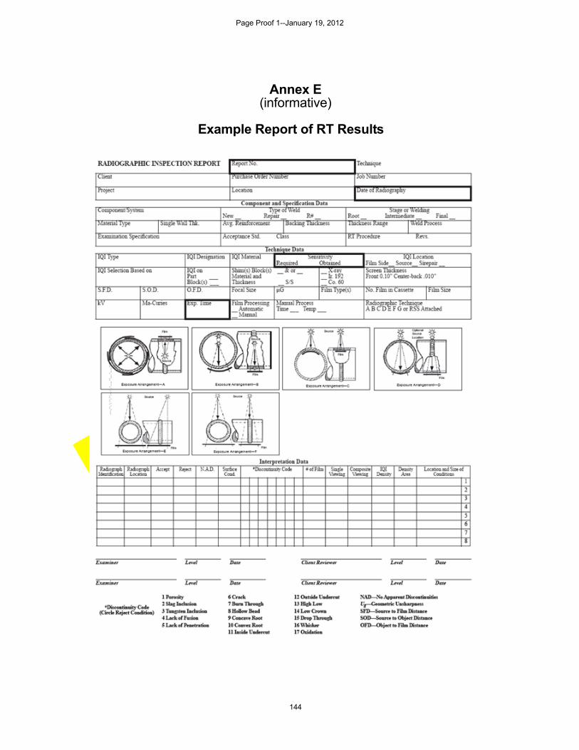
DRAFT
144
Annex E(informative)
Example Report of RT Results
Page Proof 1--January 19, 2012
DRAFT
145
Bibliography
The following codes and standards are not referenced directly in this recommended practice. Familiarity with thesedocuments may be useful to the welding engineer or inspector as they provide additional information pertaining to thisrecommended practice. For dated references, only the edition cited applies. For undated references, the latest editionof the referenced document (including any amendments) applies.
[1] API Recommended Practice 572, Inspection of Pressure Vessels
[2] API Publication 2207, Preparing Tank Bottoms for Hot Work
[3] API Publication 2217A, Guidelines for Work in Inert Confined Spaces in the Petroleum Industry
[4] ASME B16.5, Pipe Flanges and Flanged Fittings
[5] ASME B16.9, Factory-Made Wrought Steel Buttwelding Fittings
[6] ASME B16.34, Valves—Flanged, Threaded, and Welding End
[7] ASME B31.1, Power Piping
[8] AWS A2.4, Standard Symbols for Welding, Brazing, and Nondestructive Examination
[9] AWS A3.0, Standard Welding Terms and Definitions
[10] AWS B1.10, Guide for the Nondestructive Inspection of Welds
[11] AWS JWE, Jefferson’s Welding Encyclopedia
[12] AWS CM-00, Certification Manual for Welding Inspectors
[13] NB-23 10, National Board Inspection Code
10 The National Board of Boiler and Pressure Vessel Inspectors, 1055 Crupper Avenue, Columbus, Ohio 43229,www.nationalboard.org.
Page Proof 1--January 19, 2012

DRAFT
Page Proof 1--January 19, 2012

DRAFT
Page Proof 1--January 19, 2012
DRAFT
Product No. XXXXXX
Page Proof 1--January 19, 2012