* rnmhhhhlum - dtic.mil · ad-al06 781 black and veatch kansas city mo0 f/g 1/13 nat ional dam...
53
AD-AL06 781 BLACK AND VEATCH KANSAS CITY MO0 F/G 1/13 NAT IONAL DAM SAFETY PROGRAM. LAKEWOOD (EAST) DAM IMO ..373). MIECETC AUG 70 P R ZAMAN . a A AINSWORTH, H L CALLAHAN DACBN3-78-C-OIGB8 UNCLASSIFIED NL * rnmhhhhlum
-
Upload
nguyenkhanh -
Category
Documents
-
view
212 -
download
0
Transcript of * rnmhhhhlum - dtic.mil · ad-al06 781 black and veatch kansas city mo0 f/g 1/13 nat ional dam...

AD-AL06 781 BLACK AND VEATCH KANSAS CITY MO0 F/G 1/13NAT IONAL DAM SAFETY PROGRAM. LAKEWOOD (EAST) DAM IMO ..373). MIECETCAUG 70 P R ZAMAN . a A AINSWORTH, H L CALLAHAN DACBN3-78-C-OIGB8
UNCLASSIFIED NL
* rnmhhhhlum

~s44& ~J 7.' ~~jLEVEL .'' C - 7 . R
c2~~NV 44 81Al-t%4
* -'~ ~' 14' 'I £"4K
*144 w~"""w
r 'k.
""' .h.tAV.s A S~vO19?D~&~-E -v
L, ,'
$W 7,. N ,''j 1
A' '
A.,
~r'4A

UNCLASSTFTEFSECURITY CLASSIFICATION OF THIS PAGE (Pen . jDate EfnteroQ
: REPRT WAGEREAD U#SrrlUCTKMXREPORT DOCUMENTATION PAGE BZFORE COMPLVMG vOM
1. REPORT HUMER , GOVTACCClION NO. RECIPIENT'S CATALOG NUMBER
4. TITLE ( .) S TYPEOF PORT IPERoo COVERED
Phase I Dam Inspection Report - -National Dam Safety Program , Final $eprt,,Lakewood Dam - East (MO 20373) -1:. PERFORMING Or MORT NUSER
Jackson County, Missouri7. AUTHORfa) 1. CONTRACT OR GRANT NUMBER(*)Black & Veatch, Consulting Engineers
DACW3-78-CI1l48 \S. PERFORMING ORGANIZATION NAME AND ADDRESS . PROGRAM ELEMENT. PROJECT. TASK
U.S. Army Engineer District, St. Louis AREA A WORK UNIT NUMBERS
Dam Inventory and Inspection Section, LMSED-PD210 Tucker Blvd., North, St. Louis, Mo. 63101 _L_
It. CONTROLLING OFFICE NAME AND ADDRESS QbU.S. Army Engineer District, St. Louis Augw@! 78Dam Inventory and Inspection Section, LMSED-PD IS. NUMBER OF PAO=
210 Tucker Blvd., North, St. Louis, Mo. 63101 Approximately 4014. MONITORING AGENCY NAME A ADDRESS(Il dillernt from Controlling Office) Is. SECURITY CLASS. (of dat1. report)
UNCLASSIFIEDS.. DECLASSIFICATION/ DOWNGRADING
SCHEDULE
16. DISTRIBUTION STATEMENT (of this Report)
Approved for release; distribution unlimited. \u, /
17. DISTRIBUTION STATEMENT (of the absetact entered In Block 20, If 1dfntLRe*cr1)
Paul R. /Zarnan Bruce A. /Ainsworth . .... ......____..._-___-
Harry L. /Callahan .National Dam Safety Program. Lakewood... ;(East) Dam (MO 20373), Missouri - Kansas
'City Basin, Jackson County, Missouri.'Phase I Inspection Report.
19. KEY WORDS (Continue On reverse side it necesar mnd identif7 by block nember)
Dam Safety, Lake, Dam Inspection, Private Dams
2& AMTRACr (We d eeOeee * N ne..mly = identify by block numwber)
This report was prepared under the National Program of Inspection ofNon-Federal Dams. This report assesses the general condition of the dam withrespect to safety, based on available data and on visual inspection, todetermine if the dam poses hazards to human life or propert
DDo, 143 EoIO OP I OV65 IS OSOLETE NIaM 75. UNCLASSIFIED
II b$..(9....SECURTY CLASSIFICATION OF THIS PAGE (When Date Entered -

SWCUNTY CLAShIIAION OF THIS PA@U*VAM 0614 90at&
SCCURITT CLASSIFICATION OF TIS, PAG~tffte Data flnt...4

INSTRUCTIONS FOR PREPARAvIOIJ O F hEPORT DOCUMENTATION PAGE
ZSE D ILI_. The controlling DoD office will be responsible for completion of the Report Documentation Page, DD Form 1473, inall technical reports prepared by or for DoD organization,.
AMN. Since this Report Documentation Page, DD Form 1473, is used in preparing announcement*, bibliographies. and databanks, t e unclassified if possible. If a classification is required, identify the classified items on the page by the appropriate
symbol.
COMPLETION GUIDE
General. Make Blocks 1. 4, 5, 6, 7, II, 13, 15, and 16 agree with the corresponding information on the report cover. LeaveBlocks 2 and 3 blank.
Block I. Report Number. Enter the unique alphanumeric report number shown on the cover.
Block 2. Government Accession No. Leave Blank. This space is for use by the Defense Documentation Center.
Block 3. Recipient's Catalog Number. Leave blank. This space is for the use of the report recipient to assist in futureretrieval or"l -iocument.
Block 4. Title and Subtitle. Enter the title in all capital letters exactly as it appears on the publication. Titles should beunclassified whenever possible. Write out the English equivalent for Greek letters and mathematical symbols in the title (see"Abstracting Scientific and Technical Reports of Defense-sponaored RDT/E, "AD-667 000). If the report has a subtitle, this subtitleshould follow the main title, be separated by a comma or semicolon if appropriate, and be initially capitalized. If a publication has atiUe in a foreign language, translate the title into English and follow the English translation with the title in the original language.Make every effort to simplify the title before publication.
Block 5. Type of Report and Period Covered. Indicate here whether report is interim, final, etc., and, if applicable, inclusivedates of period covered, such as the life of a contract covered in a final contractor report.
Block 6. Performing Organization Report Number. Only numbers other than the official report number shown in Block 1, suchas series numbers for in-house reports or a contractor/grantee number assigned by him, will be placed in this space. If no such numbersare used, leave this space blank.
Block 7. Author(a). Include corresponding information from the report cover. Give the name(s) of the author(*) in conventionalorder (for example, John R. Doe or, if author prefers, 1. Robert Doe). In addition, list the affiliation of an author if it differs from thatof the performing organization.
Block 8. Contract or Grant Number(s). For a contractor or grantee report, enter the complete contract or grant number(s) underwhich the -rk reported was accomplished. Leave blank in in-house reports.
Block 9. Performing Organization Name and Address. For in-house reports enter the name and address, including office symbol.of the pe frm-g activity. For contractor or grantee reports enter the name and address of the contractor or grantee who prepared thereport and identify the appropriate corporate division, school, laboratory, etc., of the author. List city, state, end ZIP Code.
B Program Element, Project, Task Area, and Work Unit Numbers. Enter here the number code from the applicableDepartment of Defense form, such as the DD Form 1498, -Research and Technology Work Unit Summary" or the DD Form 1634."Research and Development Planning Summary," which identifies the program element, project, task area, and work unit or equivalentunder which the work was authorized.
Umnk IJ Controlling Office Name and Address. Enter the full, official name and address, including office symbol, of thecontrolling office. (Equate* to faadng/aponsoring agency. For definition see DoD Directive 5200.20, "Distribution Statements onTechnical Documents.")
Block 12. Report Date. Enter here the day, month, and year or month and year as shown on the cover.
Block 13. Number of Pages. Enter the total number of pages.
ofeos , Monitoring Agency Name and Address (if different from Controlling Office). For use when the controlling or fundingoffice dos not directly administer a project, contract, or grant, but delegates the administrative responsibillty to another organization.
Blocks IS & iS. Security Classification of the Report: Declassification/Downgrading Schedule of the Report. Enter in ISthe highest classification of the report. If appropriate, enter in 15a the declassiflcation/downgradng schedule of the report, using theabbreviations for declassaification/downgrading schedules listed in paragraph 4-207 of DoD 5200. I-R.
Block 16 Distribution Statement of the Report. Insert here the applicable distribution statement of the report from DODDirective 5200.20. "Distribution Statements on Technical Documents."
Block 17 Distribution Statement (of the abstract entered in Block 20, if different from the distribution statement of the report).Insert here the applicable distribution statement of the abstract from DoD Directive 5200.20, "Distribution Statements on Technical Doc-ument a."
Block IS. Supplementary Notes. Enter information not included elsewhere but useful, such as: Prepared in cooperation with... TraRlation of (or by) . .. Presented at conference of. . . To be published in ..
lock 19. Key Words. Select terms or short phrases that identify the principal subjects covered in the report, and ar.sufficiently specific and precise to be used as index entries for cataloging, conforming to standard terminology. The DoD "Thesaurusof Engineering and Scientific Terms" (TEST), AD-672 000, can be helpful.
Block 20. Abstract. The abstract should be a brief (.not to exceed 200 words) factual summary of the most significant informa-tion contained inthe report. If possible, the abstract of a classified report should be unclassified and the abstract to an unclassifiedreport should consist of publicly- releasable information. If the report contains a significant bibliography or literature sumy, mentionait hare. For information on preparing abstracts see "Abstracting Scientific and Technical Reports of Defense4ponsored RDT&E,"
' U.S. G.P.O. 1980-665-141/12)99AD-67 000.
-1 U..aPO 906 5 11119'

MISSOURI-KANSAS CITY BASIN
LAKEWOOD (EAST) DAMJACKSON COUNTY, MISSOURIMO. 20373
PHASE 1 INSPECTION REPORTNATIONAL DAM SAFETY PROGRAM
PREPARED BY: U.S. ARMY ENGINEER DISTRICT, ST. LOUIS
FOR: STATE OF MISSOURI
AUGUST 1978

DEPARTMENT OF THE ARMYST. LOUIS DISTRICT, CORPS OF E NGIERS
210 NORTH 12TH STRELrTST' LOUiS, MISSOURI 63101
SUBJECT: Lakewood (East) Lake Dam Phase I Inspection Report
This report presents the results of field inspection and evaluation ofthe Lakewood (East) Lake Dam. It was prepared under the National Program
of Inspection of Non-Federal Dams.
SUBMIE BY: SIGNED 31 JAN iq7,Chief, Engineering Division Date
APPROVED BY: SIGI FE81979Colonel, CE, District Engineer Date
NTIS GRA&I
DTIC TAB 0Unnounced 0
3ust irleat o---
DistrIbution/
Availabillty Cods
Dst
- - -- -- - - -- - ---- -

LAKEWOOD (EAST) LAKE DAM
JACKSON COUNTY, MISSOURI
MISSOURI INVENTORY NO. 20373
PHASE I INSPECTION REPORT
NATIONAL DAM SAFETY PROGRAM
PREPARED BY:
BLACK & VEATCHCONSULTING ENGINEERSKANSAS CITY, MISSOURI
UNDER DIRECTION OF
ST. LOUIS DISTRICT, CORPS OF ENGINEERS
FOR
GOVERNOR OF MISSOURI
AUGUST 1978
• L. ,.__. .._._ _i__':

PHASE I REPORT
NATIONAL DAM SAFETY PROGRAM
Name of Dam Lakewood (East) Lake DamState Located MissouriCounty Located Jackson CountyStream West Fork of May BrookDate of Inspection 8 August 1978
Lakewood (East) Lake Dam was inspected by a team of engineers fromBlack & Veatch, Consulting Engineers for the St. Louis District, Corpsof Engineers. The purpose of the inspection was to make an assessmentof the general condition of the dam with respect to safety, based uponavailable data and visual inspection, in order to determine if the damposes hazards to human life or property.
The guidelines used in the assessment were furnished by the Depart-ment of the Army, Office of the Chief of Engineers and developed withthe help of several Federal and State agencies, professional engineeringorganizations, and private engineers. Based on these guidelines, thisdam is classified as an intermediate size dam with a high downstreamhazard potential. According to the St. Louis District, Corps of Engi-neers the estimated damage zone extends 20 miles downstream of the dam.Within the first mile of the damage zone are six homes and the bridge ofone improved road. The flood plain is farmed.
Our inspection and evaluation indicate the spillway does meet thecriteria set forth in the guidelines for a dam having the above size andhazard potential. The spillway will pass the probable maximum floodwithout overtopping. Considering the volume of water impounded and theproximity of six homes and a bridge, the probable maximum flood is theappropriate spillway design flood.
Deficiencies visually observed by the inspection team were erosionon the downstream embankment slope, seepage at the right abutment, andexcessive growth of small trees and weeds along the downstream embank-ment slope. Seepage and stability analyses were not available for thisdam. To satisfy the requirements of the guidelines, seepage and stabilityanalyses should be on file for dams in the High Hazard classification.
Amn PE
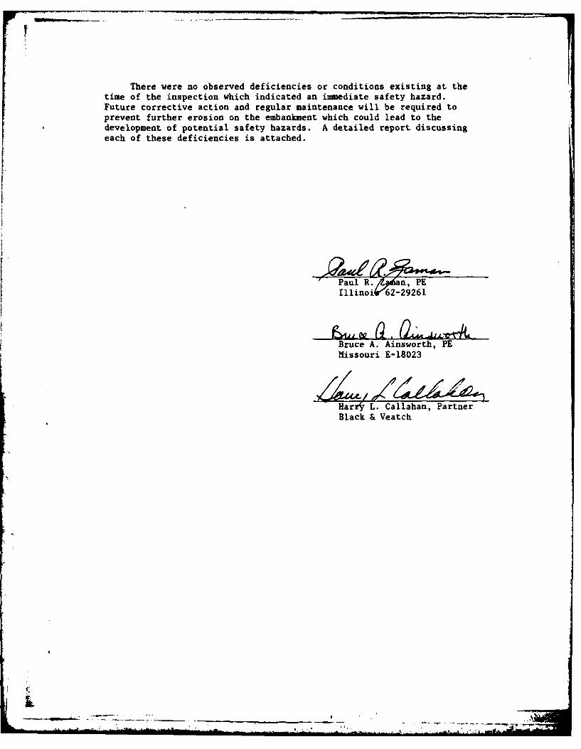
There were no observed deficiencies or conditions existing at thetime of the inspection which indicated an immediate safety hazard.Future corrective action and regular maintenance will be required toprevent further erosion on the embankment which could lead to thedevelopment of potential safety hazards. A detailed report discussingeach of these deficiencies is attached.
" Paul R..aa, PE
IllinoiiK62-29261
Bruce A. Ainsworth, PEMissouri E-18023
Harr'r L. Callahan, PartnerBlack & Veatch
_ _ _ _ _ I. . . . .. ... .... .

OVERVIEW OF DAM

PHASE I INSPECTION REPORTNATIONAL DAM SAFETY PROGRAM
LAKEWOOD (EAST) LAKE DAM
TABLE OF CONTENTS
Paragraph No. Title Page No.
SECTION 1 - PROJECT INFORMATION
1.1 General 11.2 Description of Project 11.3 Pertinent Data 3
SECTION 2 - ENGINEERING DATA
2.1 Design 62.2 Construction 62.3 Operation 62.4 Evaluation 6
SECTION 3 - VISUAL INSPECTION
3.1 Findings 73.2 Evaluation 8
SECTION 4 - OPERATIONAL PROCEDURES
4.1 Procedures 94.2 Maintenance of Dam 94.3 Maintenance of Operating Facilities 94.4 Description of Any Warning System in Effect 94.5 Evaluation 9
SECTION 5 - HYDRAULIC/HYDROLOGIC
5.1 Evaluation of Features 10
SECTION 6 - STRUCTURAL STABILITY
6.1 Evaluation of Structural Stability 13
SECTION 7 - ASSESSMENT/REMEDIAL MEASURES
7.1 Dam Assessment 147.2 Remedial Measures 14

TABLE OF CONTENTS (Cont'd)
LIST OF PLATES
Plate No. Title
I Location Map
2 Vicinity Topography
3 Plan - Lakewood (East) Lake Dam
4 Profile - Lakewood (East) Lake Dam
5 Typical Sections - Lakewood (East) Lake Dam
6 Drop Inlet Spillway - Lakewood (East) Lake Dam
7 Emergency Spillway - Lakewood (East) Lake Dam
8 Plan - Lakewood (West) Lake Dam
LIST OF PHOTOGRAPHS
Photo No. Title
I Overview of Lake
2 Top of Dam
3 Location of Newly Placed Water Line on Downstream Face(Looking South)
4 Downstream Face of Dam (Looking North)
5 Downstream Face of Dam (Looking Upstream)
6 Upstream Face of Dam and Drop Inlet Spillway(Looking South)
7 Drop Inlet Spillway and North Abutment (Looking North)
8 Drop Inlet Discharge Outlet (Looking Upstream)
9 Stilling Basin Immediately Downstream of Drop InletDischarge Outlet (Looking Downstream)
10 Discharge Channel Downstream of Drop Inlet DischargeOutlet (Looking Upstream)
APPENDIX
Appendix A - Hydrologic Computations

SECTION 1 - PROJECT INFORMATION
1.1 GENERAL
a. Authority. The National Dam Inspection Act, Public Law 92-367,authorized the Secretary of the Army, through the Corps of Engineers, toinitiate a program of safety inspection of dams throughout the UnitedStates. Pursuant to the above, the District Engineer of the St. LouisDistrict, Corps of Engineers, directed that a safety inspection of theLakewood (East) Lake Dam be made.
b. Purpose of Inspection. The purpose of the inspection was tomake an assessment of the general condition of the dam with respect tosafety, based upon available data and visual inspection, in order todetermine if the dam poses hazards to human life or property.
c. Evaluation Criteria. Criteria used to evaluate the dam werefurnished by the Department of the Army, Office of the Chief of Engi-neers, in "Recommended Guidelines for Safety Inspection of Dams". Theseguidelines were developed with the help of several Federal agencies andmany State agencies, professional engineering organizations, and privateengineers.
1.2 DESCRIPTION OF PROJECT
a. Description of Dam and Appurtenances.
(1) The dam is a rolled earth structure located in the valley ofthe West Fork of May Brook in central Jackson County, Missouri (seePlate 1). A roadway has been constructed across the top of the dam.Topography of the contributing watershed is characterized by rollinghills. Land use consists of residential areas and farm land. Topographyin the vicinity of the dam is shown on Plate 2. Lakewood Lake islocated to the west of Lakewood (East) Lake. The two lakes are connectedby a 110 feet wide boat channel, 15 feet deep at normal pool elevation(El.858.0). Lakewood Lake shall be referred to as Lakewood (West) Lakein this report.
(2) An emergency spillway channel was excavated within the limestonestrata in the aorth abutment. The roadway crossing the dam continuesacross the emergency spillway as a low water crossing (see Plate 7).
(3) A drop inlet spillway is located 80 feet upstream from thecenterline of the road across the dam near the north abutment. The dropinlet is a 10.5 by 15.0 feet vertical concrete box with two 13.75 feetwide openings normal to the longitudinal axis of the dam at E1.858.0.The drop inlet is connected to a 5 by 6 feet discharge culvert whichdischarges at E1.808.8, then drops 34 feet to the stilling basin anddownstream channel (see Plate 6).

(4) A drainage blanket was detailed as constructed along an areabeginning 34 feet downstream from the centerline of the dam extending124 feet downstream for the entire length of the dam (see Plate 5). An8 inch perforated asbestos bonded corrugated metal pipe was shown embeddedin the 8 feet thick drainage blanket at 1 foot above the bottom of theblanket. Three 12 inch asbestos bonded corrugated metal pipes extendfrom the perforated pipe to the downstream toe of the dam.
(5) A 30 inch sewer line runs through the embankment normal to thelongitudinal axis of the dam approximately 290 feet south of the dropinlet centerline.
(6) A 12 inch water main is buried parallel to the longitudinalaxis of the dam near the downstream side of the roadway on top of thedam.
(7) Pertinent physical data are given in paragraph 1.3.
b. Location. The dam is located in the central portion of JacksonCounty, Missouri, as indicated on Plate 1. The lake formed by the damis shown on the United States Geological Survey 7.5 minute seriesquadrangle maps for Blue Springs and Lake Jacomo, Missouri in Sections5, 6, 7, and 8 of T48N, R31W.
c. Size Classification. Criteria for determining the size classifi-cation of dams and impoundments are presented in the guidelines referencedin paragraph l.lc above. Based on these criteria, the dam and impound-ment are in the intermediate size category.
d. Hazard Classification. The hazard classification assigned bythe Corps of Engineers for this dam is as follows: The Lakewood (East)Dam has a high hazard potential, meaning that the dam is located wherefailure may cause loss of life and serious damage to homes; agricul-tural, industrial and commercial facilities; important public utilities;main highways or railroads. The Lakewood (East) Lake Dam has an estimateddamage zone which extends 20 miles downstream of the dam. Within thefirst mile of the damage zone are six homes and one improved road bridge.The flood plain is farmed.
e. Ownership. The dam is owned by Farm and Home Savings Associationof Nevada, Missouri, 217 Bayview, Lee's Summit, Missouri 64063.
f. Purpose of Dam. The dam forms a 110 acre recreational lake(from design calculations).
g. Design and Construction History. The dam was designed primarilyby the late Robert J. Spiegel, Consulting Engineer, Kansas City, Missouri.Construction began in 1970 by Andes and Roberts Construction Company,Independence, Missouri under the supervision of E. Daniel Weiskirk, P.E.Impoundment of water began in 1973. The boat channel between the westand east lakes was opened in 1975.
2
-- ----------- -.

h. Normal Operating Procedure. Normal rainfall, runoff, transpir-ation, evaporation, and seepage through the natural limestone and shaleabutment of the west dam all combine to maintain a relatively stablewater surface elevation.
1.3 PERTINENT DATA
a. Drainage Area - Combined drainage area of Lakewood (West) Lakeand Lakewood (East) Lake is 3,410 acres (2,210 acres, Lakewood (West) Lakeand 1,200 acres, Lakewood (East) Lake).
b. Discharge at Damsite.
(1) Normal discharge at the damsite is through the drop inletspillway.
(2) Estimated experienced maximum flood at damsite - unknown.
(3) Estimated ungated spillway capacity at maximum pool elevation -
19,600 cfs (El.868.3).
c. Elevation (Feet Above M.S.L.).
(1) Top of dam - 870.3 + (see Plate 3)
(2) Spillway crest - 859.0 (West dam box culverts), 858.0 (Eastdam drop inlet)
(3) Streambed at centerline of dam - 773.+
(4) Maximum tailwater - unknown.
d. Reservoir. Length of maximum pool - 6,200 feet +
e. Storage (Acre-feet).
(1) Top of dam - 4,810 (from design calculations for east dam);10,120 (for total of east and west lakes)
(2) Spillway crest - 2,800 (from design calculations for east lakeonly); 5,943 (for total of east and west lakes)
(3) Design Surcharge - 4,100 (from design calculations for eastlake only) 7,640 (for total of east and west lakes)
f. Reservoir Surface (Acres).
(1) Top of dam - The combined reservoir surface area of Lakewood(East) Lake and Lakewood (West) Lake is 440 acres (210 acres, east lakeand 230 acres, west lake)
3

(2) Spillway crest - The combined reservoir surface area of Lake-wood (East) Lake and Lakewood (West) Lake is 235 acres (110 acres, eastlake and 125 acres, west lake)
g. Dam.
(1) Type - rolled earth embankment
(2) Length - 1,300 feet
(3) Height - 95 feet maximum
(4) Top width - 60 feet
(5) Side Slopes - varies (see Plate 5)
(6) Zoning - Composed of impervious core supported by random fillon both faces (see Plate 5).
(7) Impervious Core - Vertically extends throughout the entireheight of the dam with a 20-foot top width and 3 to 1 side slopes (up-stream face) and 0.5 to 1 side slopes (downstream face) (see Plate 5).
(8) Cutoff - approximately 25 feet wide with 1:1 side slopes
(see Plate 5)
(9) Grout curtain - unknown.
h. Diversion and Regulating Tunnel - none.
i. Spillway.
(1) Type - concrete drop inlet (see paragraph 3.1c)
(2) Length of weir - 27.5 feet (see paragraph 3.1c)
(3) Crest elevation - 858.0 feet m.s.l. (East dam drop inlet)859.0 feet m.s.l. (West dam box culverts)
(4) Gates - none.
(5) Upstream Channel - none.
(6) Downstream Channel - Discharge from the drop inlet dischargeculvert falls to a stilling basin excavated from the limestone and shalestrata near the downstream toe of the embankment. The discharge channelextends 295 feet downstream of the stilling basin at a 0.5% slope. Thechannel then drops on an incline of 11.0 feet (horizontally) to 5.8(vertically) to the invert of four 42 inch corrugated metal pipes (Inv.El.773.5) under Bowlin Road. Flow from the culverts enters the remaining
4

500 feet of the excavated discharge channel, then joins with the naturaldownstream channel.
j. Regulating Outlets - The east lake could be lowered to theinvert elevation of the boat channel (El.843.0) by use of the outletprovided in the west dam. The west dam outlet is a 36 inch diameterreinforced concrete pipe with a wall thickness of 5-3/4 inches. A 36inch diameter Rodney Hunt Series HY-Q-280 sluice gate is provided withan 80.5 feet seating head. The pipe invert elevation is 781.0. Anoutlet structure is provided with an operator at El.868.0.
5

SECTION 2 - ENGINEERING DATA
2.1 DESIGN
Design data was made available by Andes and Roberts ConstructionCompany and Earl C. Meserve, P.E. The data included design and as-builtdrawings, hydraulic and hydrologic calculations, and post-constructioninspections and seepage flow records.
2.2 CONSTRUCTION
The dam was constructed in 1970 and 1971 by Andes and RobertsConstruction Company of Independence, Missouri. As-built drawings anddata were obtained from Andes and Roberts Construction.
2.3 OPERATION
The maximum recorded loading on the dam is unknown- Several post-construction studies have been performed since the impounding of waterbegan. In the winter of 1976 seepage measurements were undertaken byEarl C. Meserve and continued through much of 1977. Records were madeof seepage through both the East and West dams. During the period ofMay through September, 1977 a water balance study was conducted byWoodward-Clyde Consultants, Kansas City, Missouri. A visual inspectionof the dam and review of available data was performed subsequent to theabove study by Woodward-Clyde.
2.4 EVALUATION
a. Availability. Engineering data in the form of backgroundreports, as-built drawings, and construction records were available fromAndes and Roberts Construction Company and Earl C. Meserve, P.E. Noother engineering data were found.
b. Adequacy. The engineering data available were inadequate tomake a detailed assessment of design, construction, and operation.Seepage and stability analyses necessary to satisfy the requirements ofthe guidelines were not available.
c. Validity. The engineering data available were insufficient todetermine the validity of the design, construction, and operation.
6

: fA SECTION 3 - VISUAL INSPECTION
3.1 FINDINGS
a. General. A visual inspection of Lakewood (East) Lake dam wasmade on 8 August 1978. The inspection team included professional engi-neers with experience in dam design and construction, hydrologic -hydraulic engineering, and geotechnical engineering. Specific observa-tions are discussed below. No observations were made of the conditionof the upstream face of the dam below the pool elevation at the time ofthe inspection.
b. D___m. The inspection team observed the following items at thedam. An erosion ditch has formed at the downstream toe of the embankmentrunning from the dam centerline westward toward the left abutment.Erosion due to surface runoff was observed along the entire length ofthe downstream toe of the embankment. Seepage was observed at thejunction of the riprap on the downstream embankment face adjacent to thestilling basin and right abutment of approximately 2 gpm. The inspectionteam was unable to ascertain that seepage was actually passing throughthe embankment. Excessive growth of small trees and weeds along down-stream slope was observed. No evidence of sliding, cracking, or settle-ment of the embankment was observed at the time of inspection. Theoutlets for the dam's internal drainage system could not be inspecteddue to vegetal growth hindering location of the outlets.
c. Appurtenant Structures. The west dam spillway consists of aconcrete-lined approach channel with twelve 11 by 6 feet concrete boxculverts which provide the support for the roadway over the spillway.Twelve 11 by 1 by I foot blocks increase the flow level through theculverts by 1 foot. No water was discharging through the west damoutlet culvert at the time of inspection. The west dam outlet workssluice gate operator could not be checked for operation because it waslocked. A 10.5 by 15.0 feet concrete drop inlet structure permitsdischarge from the east lake at E1.858.0 which is 1 foot lower than theinvert of the 12 box culverts at the west spillway (El.859.0). Flowentering the drop inlet discharges through a 6 by 5 feet inlet dischargeculvert to a stilling basin near the downstream toe of the east dam. Anemergency spillway channel is provided on the east dam across the road(El.862.0). Flow from the east reservoir must pass through either thedrop inlet or the boat channel. The drop inlet and emergency spillwayappear in good condition. A 30-inch gravity sewer is located approxi-mately 290 feet south of the drop inlet of the east dam. The sewer,reportedly, may be shut off by using a valve located on the upstreamface of the dam. The valve was not observed at the time of inspection.
d. Reservoir Area. No slides or excessive erosion due to waveaction were observed along the shore of the reservoir.
7

e. Downstream Channel. Heavy vegetation and mild channel slopestypical of streams in the area characterize the channel downstream ofthe spillway. A wooden wall at the crest of the incline immediatelyupstream of Bowlin Road retains water to a depth of approximately 4 to 5feet in the discharge channel and stilling basin. Seepage was noted atvarious locations between the Ladora Shale layers.
3.2 EVALUATION
Items observed in the visual inspection which need to be monitoredare seepage at the right abutment and erosion of the downstream toe ofthe embankment. These items if left uncontrolled could lead to furtherdeterioration of the embankment integrity resulting in an increasedpotential of failure.
8
, .

SECTION 4 - OPERATIONAL PROCEDURES
4.1 PROCEDURES
The pool is primarily controlled by rainfall, runoff, evaporation,seepage through the natural limestone and shale abutment of the westdam, and capacity of the uncontrolled spillway. A staff gage and recorderare operable.
4.2 MAINTENANCE OF DAM
Maintenance performed was unknown.
4.3 MAINTENANCE OF OPERATING FACILITIES
No operating facilities exist at this dam. The outlet structure atthe west dam shows no evidence of maintenance.
4.4 DESCRIPTION OF ANY WARNING SYSTEM IN EFFECT
The inspection team is not aware of any existing warning system forthis dam.
4.5 EVALUATION
Seepage at the right abutment along with erosion and vegetation onthe downstream slope increase the potential for failure and warrantregular monitoring and control.
9

I
SECTION 5 - HYDRAULIC/HYDROLOGIC
5.1 EVALUATION OF FEATURES
a. Design Data. Report and as-built drawings were available.Design calculations were available for hydrology and hydraulics.
The embankment and appurtenant structures were designed primarilyby Robert J. Speigel, Consulting Engineer. The hydraulic and hydrologiccomputations were performed by Earl C. Meserve, Consulting Engineer.Mr. Meserve's calculations show the inflow hydrographs for the east andwest lakes were calculated by using Clark's unitgraph with parameters ofTc = 2.0 hours and R = 2.0 hours. The inflows were calculated based ona rainfall of 50 percent of the 6-hour probable maximum precipitation or13.0 inches in 6 hours. The assumption was made that 100 percent of theprecipitation ran off.
With the design infows calculated for each lake as indicated above,the peak inflows for the east and west lakes were determined to be 3,181cfs and 5,709 cfs respectively. A peak inflow of 8,859 cfs for 50percent of the probable maximum flood, referred to as the "spillwaydesign flood (SDF)" in the calculations, was routed through the reser-voirs. To determine outflow discharges for the reservoirs the dischargeratings for the spillways and outlets were calculated individually.Discharges for the twelve 11 by 6 feet box culverts of the west damspillway were calculated by use of the broad-crested weir equation:
Q = CLH1 .5
C = 2.6, L = 132 feet, H = head on weir
To force the majority of the outflow from the two reservoirs to dischargethrough the east dam drop inlet, twelve 11 by 1 by 1 foot blocks wereplaced at the inverts of the west dam spillway box culverts to preventflow in the west spillway unless inflows resulted in the lake levelsexceeding an elevation 1 foot higher than the drop inlet elevation. Therating curve for the west spillway was changed only by using the samedischarges calculated previously and increasing the corresponding eleva-tions by I foot. The resulting design discharge capacity with thereservoir level at the top of dam for the west dam spillway box culvertswas calculated at 9,270 cfs. The east dam drop inlet yielded a designdischarge capacity with the reservoir level at the top of dam of 1,010cfs by calculating the controlling discharge in the 6 by 5 feet inletdischarge culvert through the dam using the equation:
Q = A (2gH) 0.5 2A = 30 sq ft, g 32.2 ft/sec 2 , H 17.8 feet
10

When the inlet discharge culvert was not flowing full, at E1.865.0 orbelow, the discharge was controlled by the equation:
Q = CLH1 .5
C = varied from 4.0 to 1.9 depending on the head on the weirL = 27.5 feet, H = head on the weir up to 8 feet at E1.865.0
An emergency spillway was designed for the west abutment of the eastdam. The design discharges for the east dam emergency spillway werecalculated using the equation:
Q = CLH1 .5
C = 3.52, L = 40 feet, and H = head on the weir
The design discharge at the top of dam was 1,570 cfs. The combineddesign outlet discharge at the top of dam was determined to be 11,850cfs. At the design freeboard of 6 feet below top of dam (El.863.0) thedesign discharge capacity would total 3,540 cfs. The hydraulic effectof the boat channel connecting the two reservoirs was considered negli-gible in determining the hydraulics of the reservoirs. The boat channeldid, however, provide justification for combining the hydraulic informa-tion of the two reservoirs to act as a single reservoir where lakeelevations exceeded the invert of the boat channel (El.843.0).
b. Experience Data. The drainage area and lake surface area aredeveloped from USGS Lees Summit and Lake Jacomo, Missouri QuadrangleMaps. The spillway and dam layout are from drawings provided by Andesand Roberts Construction Company.
c. Visual Observations.
(1) The drop inlet spillway, discharge outlet, and the spillwaydischarge channel are in good condition. The emergency spillway appearsin good condition.
(2) Drawdown facilities are available to lower the pool to anelevation equivalent to the boat channel invert (El.843.0) (see paragraph3.1c).
(3) The drop inlet spillway and discharge culvert are located nearthe north abutment. Spillway releases should not endanger the integrityof the dam.
d. Overtopping Potential. The spillway will pass the probablemaximum flood (19,600 cfs), which is the spillway design flood recommendedby the guidelines, without overtopping. The probable maximum flood isdefined as the flood discharge thst may be expected from the most severecombination of critical meteorologic and hydrologic conditions that arereasonably possible in the region. Failure of the Lakewood (West) Damis not anticipated to pose a serious hazard to the Lakewood (East) Dam
11!
,__ _ _ _ _ _ _ _ _ _ _ _ _ _ _ _ _ _ _ _ _ _ _ _ _ _~J.

due to the maximum drawdown from normal pool level being restricted to15 feet by the boat channel invert (El.843.0). Failure of upstreamwater impoundments shown on the 1975 revised USGS map would not have asignificant impact on the hydrologic or hydraulic analysis as the storageof these reservoirs was not considered. However the effect of totalfailure of these dams has not been investigated.
According to the St. Louis District, Corps of Engineers, the esti-mated damage zone extends 20 miles downstream of the dam. Within thefirst mile of the damage zone are six homes and the bridge of oneimproved road. The flood plain is farmed.
12

SECTION 6 - STRUCTURAL STABILITY
6.1 EVALUATION OF STRUCTURAL STABILITY
a. Visual Observations. Visual observations of conditions whichaffect the structural stability of this dam are discussed in Section 3,paragraph 3.1b.
b. Design and Construction Data. No design data relating to the
structural stability of the dam were found.
c. Operating Records. No operational records exist.
d. Post Construction Changes. No post construction changes existwhich will affect the structural stability of the dam.
e. Seismic Stability. The dam is located in Seismic Zone 1 whichis a zone of minor seismic risk. A properly designed and constructedearth dam using sound engineering principles and conservatism shouldpose no serious stability problems during earthquakes in this zone.
The seismic stability of an earth dam is dependent upon a number offactors: The important factors being embankment and foundation materialsand shear strengths; abutment materials, conditions, and strength;embankment zoning; and embankment geometry. Adequate descriptions ofembankment design parameters, foundation and abutment conditions, orstatic stability analyses to assess the seismic stability of this embank-ment were not available and therefore no inferences will be made regard-ing the seismic stability. An assessment of the seismic stabilityshould be included as a part of the stability analysis required by theguidelines.
13
Ail

SECTION 7 - ASSESSMENT/REMEDIAL MEASURES
7.1 DAM ASSESSMENT
a. Safety. Several items were noted during the visual inspectionby the inspection team which should be monitored or controlled. Erosionof the downstream toe of the embankment, vegetal growth on the downstreamslope, and seepage at the right abutment are of concern.
b. Adequacy of Information. Due to the unavailability of engineeringdesign data on the embankment and the absence of seepage and stabilityanalyses, the conclusions in this report were based on performancehistory, review of drawings, hydrologic/hydraulic calculations, andconstruction information, and visual conditions. The inspection teamconsiders that these data are sufficient to support the conclusionsherein. However, seepage and stability analyses comparable to thoserequired in the guidelines are necessary to satisfy the requirements ofthe guidelines.
c. Urgency. A program should be developed as soon as possible tomonitor at regular intervals the deficiencies described in this report.The remedial measures recommended in paragraph 7.2 could be accomplishednow or delayed until observations of this monitoring program and/or therecommendation of a qualified engineer indicate the necessity for action.If the safety deficiencies listed in paragraph 7.1a are not corrected,they are anticipated to continue to deteriorate and lead to a seriouspotential of failure. Presently, immediate action is not considerednecessary.
d. Necessity for Phase II. The Phase I investigation does notraise any serious questions relating to the safety of the dam or identifyany serious dangers that would require a Phase II investigation.
e. Seismic Stability. This dam is located in Seismic Zone 1.Because stability analyses are not available, the seismic stability ofthe dam cannot be assessed. An assessment of the seismic stabilityshould be included as part of the stability analysis required by theguidelines.
7.2 REMEDIAL MEASURES
a. Alternatives. No measures are recommended.
b. O&M Maintenance and Procedures. The following O&M maintenanceand procedures are recommended:
(1) Check the downstream face of the dam periodically for seepageand stability problems. If increased seepage flows are observed ordeterioration of the foundations of the embankment noted, the dam shouldbe inspected and the pending condition evaluated by an engineer experi-enced in design and construction of earthen dams.
14

(2) Measures to prevent further erosion of the downstream toe ofthe embankment should be undertaken.
(3) A regular maintenance program should be initiated to controlthe growth on downstream slope of the dam.
(4) A detailed inspection of the dam should be made at least everyyear by an engineer experienced in design and construction of dams.More frequent inspections may be required if items of distress areobserved other than those already mentioned.
(5) Seepage and stability analyses should be performed by a profes-sional engineer experienced in the design and construction of dams.
15
- ..-.-------.-------
.. ,
-..

I N
70____ KA NS A
40
C_-1J T
LAKEW
(WEST)
KLI
UNT
LAENOH
------ 7j~Fl

KA
D (EAST)ST)
LE(EA
LAKEK
77NL E AWOTAFAINGAAA (ES)LK
I~ 0 K
LPLAT

I.,i 'A , "' (ItJ %jJ~tf~j~Ii
7)3 ~ ~ ,K 1h~2-
(6 9
N,~ BI"'0
a .. ,"-. U I,--
me chapel I NCour~y omerfur
/1 /\ t9 976r .
Ho *\ T all
S. A ,.
2 '
r, 111 SCL.NFE
-7-

--- TOP OF DAM EL. 8
L A K E W 0 0 D
SNUMBEROF PHOW

1'
I8I 9 l
I I .- SPILLWAY
SANITARY OUTLET BOX
SEWERI
EL. 870.3 7
INTAKE -
TOWER--
D (E A S T) L A K E
UMBER a DIRECTION 0 L00 200
F PHOTOGRAPH SCALE' F LAKEWOOD (EAST) LAKE.,, TPLAN
PLATE 3

FONTANA SHALE TOP OF DA
L I E TON EHUSH PUC KNEY
MOUND CREEK
________________LADORE SHALE
C C
__________PLEAS]

P OF DAM
FONTANA SHALE
STARK -GALESBURGSHALE
'*-BETHANY FALLS
FRESONESINDAIG
~PLEASN T ~ SHSAAL
LAKER WOOH(AS)LAK
PROFILEPLATE 4

601
WATER LEVEL60
RANDOM FILL--
3.5: 1SLOPEIMPERVIOUS
FIL

,,OP OF DAMEL. 870.3
2:1 SLOPE
-3 SLOPEP
,DRAINAGE
IOsRANDOM FI LL 3*1 SLOPE
J/
,--CUTOFF
LAKEWOOD (EAST) LAKETYPICAL SECTION
PLATE

STILLINGDISCHARGE CULVERT
P L
STILLING EL. 808.8\
EL. 774.8
S E CT,1

IERT /1
DROP INLETP L AN SPILLWAY
TOP OF DAM
WPATE EE-~~~~L 858.0--"-----

TOP OF DAM
L A K E wOO 0D
(E A S T)
L A K E

00
50 100
SCA .LE IN FEET LAKE WOOD (EAST) LAKEEMERGENCY SPILLWAY
PLATE71

PILLW Y - OUTLE'
CREST EL.8 8.02
LA KE OOD- (
4_ _ _ _ _ _ _ _ _ _ _
K E W 0

---- - -- DRA INAGE BLA N KET , -,
,a--TOP OF DAM EL. 869. 1--
OUTLET WORKS SANITARYSEWER
I
I
1
0 (W ES T) L A KE
0 100 200
S0 E l'N FEET LAKEWOOD (WEST) LAKEPLAN
PLATE 8I

PHOTO NO. 1: OVERVIEW OF LAKE
PHOTO NO. 2: TOP OF DAM

PHOTO NO. 3: LOCATION OF NEWLY PLACED WATER LINE ON
DOWNSTREAM FACE(Looking South)
PHOTO NO. 4: DOWNSTREAM FACE OF DAM (Looking North).

PHOTO NO. 5: DOWNSTREAM FACE OF DAM(Looking Upstream)
PHOTO NO. 6: UPSTREAM FACE OF DAM AND DROP INLET SPILLWAY(Looking South)

PHOTO NO.. 7: DROP INLET SPILLWAY, EMERGENCY SPILLWAY, AND NORTH ABUTMENT
(Looking North)
PHOTO NO. 8: DROP INLET DISCHARGE OUTLET (Looking Upstream)

PHOTO NO. 9: STILLING BASIN IMMEDIATELY DOWNSTREAM OFDROP INLET DISCHARGE OUTLET(Looking Downstream)
PHOTO NO. 10: DISCHARGE CHANNEL DOWNSTREAM OF DROPINLET DISCHARGE OUTLET(Looking Upstream)

APPENDIX A
HYDROLOGIC COMPUTATIONS

HYDROLOGIC COMPUTATIONS
I. The Soil Conservation Service (SCS) dimensionless unit hydrographand HEC-I (1) were used to develop the inflow hydrograph (see Plate A-i)and hydrologic inputs are as follows:
a. Twenty-four hour, probable maximum precipitation determinedfrom U.S. Weather Bureau Hydrometeorological Report No. 33:
200 square mile, 24 hour rainfall - 24.8 inches
10 square mile, 6 hour percent of 24 hour200 square mile rainfall - 101%
10 square mile, 12 hour percent of 24 hour200 square mile rainfall - 120%
10 square mile, 24 hour percent of 24 hour200 square mile rainfall - 130%
b. Drainage area = 3,410 acres(2,210 acres, West Lake + 1,200 acres, East Lake)
c. Time of concentration: Tc = (11.9 x L3/H)0 .38 5 = 18 minutes(East Lake), 47 minutes (West Lake) (L = length of longestwatercourse in miles, H = elevation difference in feet)(2)
d. Losses were determined in accordance with SCS methods fordetermining runoff using a curve number of 76 and antecedent moisturecondition III.
2. The spillway release rates for the box culverts on the west damwere determined by using the equation:
Q = wg0 5 (H/l.5)1.5w 132 feet (net width of box culverts),H = head above the box culvert invert
When the reservoir elevation rose over the top of road over the boxculverts, additional discharge was determined using the broadcrestedweir equation:
Q = CLH1 "
C = 2.6, L = variable length of weir in feet, H head onthe weir (above the top of road elevation)
A-I
. . . .. . . ..... .. . . ..-. - , . . -

Releases from the drop inlet spillway of the.east dam were calculated byusing:
Q = CLH1.5
C = 2.98 to 3.32, L = 27.5 feet, H = head on inlet weir.
The drop inlet discharge culvert controlled the flow from the inletwhere the reservoir level exceeded E1.862.0. At this point the dischargewas calculated by using the equation:
0.5Q =.11 9 .03h
hL = head measured from the top of the discharge culvert
to the reservoir elevation.
The above equation was derived from:
L = KbV 2/2g + n2 V 2L/2.22R 1 "3 3 + V2 /2g
Kb = 1.5, n = 0.018, L = 256 feet, R = 1.36 feet using an area
of 30 sq. ft. for the discharge culvert
Discharges from the east dam emergency spillway were determined from theequation:
Q = CLH 1.5
C = 3.087, L = varied length of weir in feet,H = head on the weir in feet.
The discharges as calculated above were combined at their respectiveelevations to produce a discharge rating curve for the two interconnectedreservoirs.
3. The elevation-storage relationship above normal pool elevation wasconstructed by planimetering the area enclosed within each contour abovenormal pool. The storage between two elevations was computed by multi-plying the average of the areas at the two elevations by the elevationdifference. The summation of these increments below a given elevationis the storage below that level.
4. Using HEC-l the inflow hydrographs for the east and west reservoirsare computed, then the combined floods are routed through the spillwayusing modified Puls to determine the capability of the spillway. Inflowand outflow hydrographs are shown on Plate A-1.
A-2

(1) U.S. Army Corps of Engineers, Hydrologic Engineering Center,Flood Hydrograph Package (HEC-l), Dam Safety Version, July, 1978,Davis, California.
(2) U.S. Department of the Interior, Bureau of Reclamation,Design of Small Dams, 1974, Washington, D.C.
A-3
-S

T T-F
ff71... _
*. . . . . . . . . . . ._ _
......... .....
7 = 71T.t ... .. IFL W PEAK .RY.t. ...6 . .
. o. o . . .. . . . . . . . . . . . . . . .
. t..... ... LAE.. A E
.. ~~......... ......... A L M XIU F O D..........;~< ....... HY GAH ... ET.......
. . . ... :.... _____ ADS AG -TMEC R E... PLAT A-..
. . . . . . . . . . . .