. nta $$3**'t.' I ROTTLER - d27kz3h5jc94vh.cloudfront.net Manuals/NCA Manual.pdf · button with...
16
l,\\\\\*1f) I I ? ? ? t I ? e e e t, I e e e e I 2 e a e e e e e ? a e e e d e 51$l'\\\\atA.'\. nta" $$3**'t.' ROTTLER MANUFACTURING NCA Boring Bar o P E RAT I O N S A NDu'i\/Al NTE NANC E @ MANUFACTURED BY: ROTTLER MANUFACTURI NG COMPANY 8029 South 200th Street Kent Washington 98032 USA Phone: (253) 872-7050 Fax: (253) 395-0230 NOTE: WHEN ORDERING REPLACEMENT PARTS' PLEASE GIVE THE MODEL AND SERIAL NUMBER' 1 I I s 1 1 1 s t 1 1 t s t s I t t t t $ t 1 t t 1 t s s t 1 t 19 $ t 1 t ($ $ $ 1 s t 3 1 i s s $ T s f $ $ 3 e & e I e e 2 e e e ORDER BY PART NUMBER.
Transcript of . nta $$3**'t.' I ROTTLER - d27kz3h5jc94vh.cloudfront.net Manuals/NCA Manual.pdf · button with...

l,\\\\\*1f)II???tI?eeet,IeeeeI2eaeeeee?aeeede
51$l'\\\\atA.'\. nta" $$3**'t.'
ROTTLERMANUFACTURING
NCA
Boring Bar
o P E RAT I O N S A
NDu'i\/Al NTE NANC E
@
MANUFACTURED BY:
ROTTLER MANUFACTURI NG COMPANY8029 South 200th Street
Kent Washington 98032 USAPhone: (253) 872-7050Fax: (253) 395-0230
NOTE: WHEN ORDERING REPLACEMENT PARTS'
PLEASE GIVE THE MODEL AND SERIAL NUMBER'
1IIs111st11tstsItttt$t1tt1tsst1t19
$t1t($$$1st31iss$Tsf$$3
e&eIee2eee
ORDER BY PART NUMBER.

DESCRIPTION
The Model NCA bars are single point tool precision
portabie boring bars, complete with tooling necessary
io, standard engine reboring work' All feeds and
traverses are Power operated and controlled from the
upper gear housing unit' Power is supplied by3/4 H'P'
We suggest, before attemPting to bore, you clamp the
bar over an oPen area and actuate the controls to
become familiar with them'
l. Cottt, lock release lever is located under cen-
tering knob. Use yow thumb to raise lever in order to
eitherinsert or remove tool holder'
2. Feed lever is latching lever on side of bar' Press
down until lever latches to engage cutting feed' To
disengage, press neutral feed release arm which will
,rrrl.tJh-lever and allow it to return to neutral posi-
tion. Lift feed lever until it latches to engage raPid
return travel. Bar will automatically return to neutral
upon reaching toP of travel' If you wish to return bar
to neutral o,til. i, is in rapid up travel, again press
neutral feed release which will unlatch lever and
allow it to retutn to neutral position'
3. The fast down travel buffon is located next to
the feed lever. Check feed lever to make sure it is in
neutral position before pressing' It is most convenient
constant sPeed AC' General
with the unit. Housings are
to incorporate the Iightest
sacrificing rigiditY.
Crjlrtit LO{r!TELEASE
PRESJ DCVN;OA itxl)i-ii I t
Electric motor integral
aluminum alloY in orderpossible weight without
coNTROtSto operate fast down by extending fingers around
back end of upper housing and exerting Pressure on
button with palm of hand' The button should be
pressed in firmly and not allowed to ratchet' This
.orrt.ol is spring loaded and will release when you
release pressure.
You will note the stoP rod, that is held in base
castiog by thumb screw, has a cone shaped end
which will release cutting feed when it contacts
lever. This is most conveniently raised uP ^nd
locked
by thumb' screw in PloPer position on completion of
first bore cut.
4. The NCA rype boring bars are equipped with a
manual travel that is actuated by attachingthehandle
to the pinned &ive shaft extending from the motor
drive. This travel is an auxiliary unit, and should al-
ways be left in the full up position after using'
Normal procedure is to rapid travel or feed spindle to
point requiring manual travel, which might be cham-
i.riog, .oontJr-bo.ing' or facing sll1v;s' and t-hen
pr..J.ai"g with the manual feed' If back feeding
should be necessary, run hand travel down first and
then rapid travel spindle down to where tooi can be
in serted.
5. A 2-speed selector is also furnished on the NCA
.yp. rnuciioes. To engage in falt spindle RPM' tum
,p'..a ""t""tor knob tttloding ftom geat pot clock-
*i". ,o end of cravel. Revetse procedure to engage in
low. It may be necessary to rotate top feed screw
knob slightiy while doiog this, to allow gears to mesh
properlY.
In genera! the high speed may be used for single
fini"sh cuts to .030 oveisize and uP to' 3/2" dtameter'
A to* speed should be used for rough sleeving cuts
op ,o ,ni" diameter and ior all cuts abnte 1%"' \e
,..orn^.od taking mavimum cut of '080 on low speed
up to )/t" and a maximum cut of 'O6O on diameter of
latger bores,
,MPORIANI : Alwoys give s*iol numbq ol the Bq when ordering porfs'
2

OPER ATING INSTR.UCTIONS
Note: When bar is shipped from factory the machined
surfaces are protected with rust veto. After uncrating,use clean cloth dampened with kerosene and remove
the protective oil.
We recommend, particularly for ope!ators unfamiliarwith the NCA bars, !o practice on a junk block inorder to become acquainted with all controls and
details connected with the use of this machine. Ifyou plan to chamfer bores, we also recommend prac-ticing this operarion (See No. 8)
l. Carefully clean and file off high spots, threadburrs, etc. on top of cylinder blocks. When using the
vacuum chip remover take cate to remove oil and
grease film from cylinders in order to prevent eventualloading of air passages and vacuum filters.
2. M"""*. each cylinder. Determine the amount ofmetal to be removed from the measurement of cylinderwhich shows the most wear.
3. In".rt the proper size wing in the hold down
clamp for the diameter of cyiinder and adiust hold
down length so that )/8" anchoting screw will have
ar leasr ^ 3/8" length of thread holding. After placing
through bar base, reach through cylinder and make
sure there is an adequate square surface where you
intend to set hold down. Beware of fillets and cham-
fers around clamping area, In blocks which haverelief, for connecting rod clearance, the hold down
lug will most often straddle the reiief with adequateholding surface on each corner. It is convenient toinsert one of the 5/8" bolts in rhe hold down to holdit while expanding the'wing with the T wrench. Use
light tension on T wrench. Excessive tightening willresult in distortion of bores and marks in finishedcy i inder s.
Self centering onchorogadevice, odiustoble inlength ond diometer in
oll size cylinders.
In many blocks it is possible to utilize the stud holes
to anchor the bar, although caP screws to fit these
holes are not furnished as standard equipment.
In any event attemPt to set the hold down device so
the boring bar can be pivoted to bore adiacent cyl-inders on either side and hold down bolt is as closeto spindle as practicable.
Check also to make sure there is good contact of
boring bar base and block on all sides of hold down.
If this is questionable, particularly on long industrialjobs, it is advisable to use additional clamps after
centering bar, such as milling machine rype clamp,on the steps of the base.
Place the bar with spindle over the hole to be t'oredand insert the bolt in the hoid down without tight-ening. Check to make sure tool holder is not in bar
and centering fingers are not extended.
IMP0RTANT: Always give seriol number
3
After locating fingers properly, extend them by
turning top centering knob and exert tension on the
knob while tightening hold down bolt. Do not overtighten. Approximately 21 lb. tension on B" 'wrenchis adequate. Before tightening hold down bolt, it isadvisable to rock bar siightly to make sure fingersare making positive contact with cylinder wail.
Retract fingers back into head and retwn bar to up
position by latching feed lever in up position.
o{ the Bar when ordering parls.
CENTERING
Start motor and pres s fast down button which willrapidly feed bar into cylinder for centering. It isusually desirabie to locate fingers iust under thering wear ridge. Dear in mind that No. 2 and 4 cen'tering fingers are slightiy higher chan others and mustbe under the ridge. The best method of centeringrvhen little stock is left for cleanup is to rotatespindle w.ith top knob so that 2 fingers straddle thegreatest wear under the ridge. lhese wear pocketsgenerally occur in line with the block.

4. on NCA 00 bars, it is necessary to change fingers
to accomodace the entire range' The most convenient
method is to lay the bar on bench, control side uP'
Run the spindle down a few inches with the fastdown
feed, shut the motor off and run the fingers out with
centering knob. Insen the other fingers in the siots
being carefui to match the numbers on the fingers to
the iutbers on the slots' Hold all fingers inward with
one hand and rotate centering knob - first to right and
then to left retracting them into head' Check to see
that all fingers are retracted equally and retum bar
to up position.
SFIARPENING CUTTER
5. ttre performance of yoru boring bar and quality of
*ork it will do is almost entirely dependent on the
care of the cutting tool' It is the most frequent cause
of size and finish problems in boring'
Sharpening of the toolon NCA baris done by inserting
tool holder in the shaipening Jig slot' Then insert
the J ig shank in the hole provided in the upPer
housing and sharpen bit on the small diamond wheel
provided on the large knob' Always make sure you
"i,urp"n the tool on the side of the diamond that is
,rr.,rring toward the top face of the bit' Strarpening on
th" **ng side can readily chip the point' (Refer to
control Picture)
When sharpening use very light Pressure' moving the
tool back and forth across the diamonri wheel to
improve cutting and prevent grooving of diamond'
After sharpening a number of times &ess exces s
steel away from carbide on grinding wheel' This willfacilitate use of chip remover hoods and make for
quicker sharpening. Diamond wheel is designed for
carbide only. Steel tends to load it'
In the accompanying sketch, letters A' B' D col:e-
spond to the letters indicated on yotn sharpening iig'in oth.r words, when your jig is set in the A posirion
it will sharpen the "A" land as shown in the sketch'
ACTUAL SIZE
,MPORTANI : Always giva serial number oi the Bor when ordering Parts'

The most critical point of this sharpening is .the
width of the "8" land (as indicated by tbe diagonal
line shading). This width should be maintained at
about .015 to .020 ot 7f 64". This width is held by
cuttinS back the D land as required.
In the event your bar chatters or bores a rough finishat the bottom of the cylinder, it is very probable this
"B" lsnd is too wide.
The A cutting land is not critical as to width but
should be maintained in good condition to obtain free
cutting, particularly on heavy cuts.
The top surface of the bit is finely finished at the
factory and requires no further resurfacing. This also
means no honing or in any way attemPting to break
off the chip that sometimes seems to be apparenc'
The practice of doing these things will inevitablyresult in poor surface finish and impair the accr:racy
of che machine.
The frequency of sharpening the bit required willvary depending on the ryPe of iron being bored' A sixcylinder block can sometimes be bored without re-
sharpening and often it is advisable to touch up
the cutting tool on every hole for best results'
TOOL SETTING5. Tool Setting. One cut is adequate to finish boresto .040 oversize. If tool is properly sharpened placecutter and proper tool holder in mike. Hold tool bitlightly against mike anvil and loosen allen screwwith wing wrench. Gently let tool holder slide backto make contact with mike spindle. This procedure
will prevent chipping carbide. This mike will readdirectly to the size you wish to bore. However, bear
in mind there is .050 to a revolution rather than .025
as on conventional mikes. Set mike to. size you wishand tighten set screw lightly. Back off mike.andtighten set screw. Here again excessive tighreningonly tends to nick mike anvil and make future setringdifficult. After tightening, recheck size.
7. Make sure tool holder and tool holder slot in head
are free from dirt. Insert tool in slot at the same timelifting the cutter lock lever under the centering knob.
Do not release lever until you are sure cucter is fullyback and latched.
FOR CHIP
Insert proper length vacuum hood in hole ptovided incutter head and press in until tool bit tip exrends out
of hole in hood at least .02J. Insen vacuum goose-
neck in ball bearing on toP of centering knob. Start
vacuutn motor.
Latch feed lever in up position and when bar reaches
top turn motor off. Remove vacuum hood and tool
,ilPORfAN|: Always givc saiol numbcr ol thc Bor when otdaing ports.
5
BORINGStart boring bar motor and latch feed lever in downposition. When bar has completed boring, set stoP
rod so lever will be thrown into neutral position'Stop rod will then be set for the other holes on the
same cylinder block.
RETOVER USE ONLY
holder with tool puller. (always remove tool holderafter boring) Loosen anchor bolt and proceed to nexccylinder. (If bore is to be chamfered with bar see
No. 8). This should be done before loosening anchorbolt. If vacuum is used, a cylinder block can gen-
erally be bored before emptying filter bag. Keep bag
and filter clean. An oil saturated bag or filter willrestrict the flow of air.

8. If chamfering is to be done at toP of bore the
special chamfering bit and tool holder must be used.
Tool may be set by either insening in head and
approximating setting or place in mike and set aPProx-
imately .100 over bore size. Insen tool in cufter
head, start motor and latch feed in down position.
Hold thumb on feed lever release atm and press when
CHAI,IFERING
ROTTLER SMALL ENGINE
(Adapter Plate nO-27)
number o{ lhe Bor
6
tool has developed adequate chamfer. You will findthis can be done very quickly and with surprisingconsistancy after becomi ng f aniliar wirh it' On NC A
type bars chamf ering may be done w.ith standard toolhoider if hand travel is used. For most convenientchamfering, we recommend use of CH'2 chamfer tool.
BORING STAND
Make sure block is clean on top mounting surface and
is not sufficiently warped that ir might rock afterclamping to produce an inaccutate bore.
Place cylinder r:nder clamping hole that is slightlylarger than cylinder bore. Swing ciamp body under
cylinder so that clamp arms may be placed in positionto most rigidly clamp cylinder block andadjustheight'Light finger rip pressure on the two clamp screws isall that is required to hold cyl.inder, and ciamping
pressure will be further increased by locking boring
bar after centering. (Over-tightening of clamp screwmay damage the stand). Ve suggest to become famil-iar with clamp, operator check by attemptirg to slideclamped block by striking with hand.
li{ost cylinders chat are integral with the crank casecan easily be clamped by swinging clamps inside ofthe case.
If there is a question of adequate clamping on rhistype of motor or an odd shaped cylinder, use a C clamp
or machinist clamp to further secure the block. (Do
not over-t.i.ghten c-lamp screws. )
Place boring bar on piate and insert :/S b"tt in holeprovided in piate. Traverse bar down for centeringand return ro top. Insert sized cutting tool. Proceedwith boring cycle - always remove tool after boring.
If you are boring a blind hoie, measure with scale rhe
distance from the top of the boring piate to the depthyo'r wish the cutter to bore (Distance'A).
Using an off set tool bit, feed spindle down until toolbit t.ip is level with top of adapter piate. Shut mororoff and with scale measure same Distance A from topfe.l.t-retainer on base to a scribed pencil mark up thespindle. Start motor, engage feed and press feed re-lease button when pencil mark is level with top offelt reta-iner. If you have more than one of these cyl-inders, set sroP rod for automatic stop from pencilmark. Retum bar to top and always removetoolholder'
INSTRUCTIONS
** &
&q*i;@
,MPORTANT: Alwoys give seriol when ordeting porls.

SERVICE ond iIAINTENANCE
LUBR,ICATION
UPPER HOUSING GEARS
After approximately 6000 bores we recommend re- 6 parts of grease to one part oil' Do noc overloa'd'
placing grease using Union Unoba F-1 Light. Dilute l/4 Pint should be sufficient' Lubriplate 930AAA
may be substituted.
IIOTOR HOUSING
Same as upper housing. Use approximately L/8 pint of the Unoba F-lLight and dilute 6 to 1.
OUTER SPINDLE
Occasionally apply light film of very light oil to outet spindle'
INNER SPINDLE
After 3000 holes approximately a thimble futl of oil in the keyway hole of the outer spindle-
SERVICEDRIVE PIN
A &ive pin, retained by a collar, is provided in rhe head. This Pin should occasionally be replaced
lower end of the feed screw. This will shear, in some regardless of breakage as it tends to weaa from the
cases, when an extreme load is exerted on the cutter constant shock of intermittent cuts.
REPLACEI'{ENT INSTRUCTIONS
l. Lift retaining coliar above pin hole. 5. .Hola flst dow.n,travel button in and rorate sharp'
ening knob to right until screw is fully down and
Z Hota fast down travel button in and manually drive holes line up.
rotate sharpening knob by hand to the left untilbottom of screw is clear of the motor &ive shaft. 6. Use pointed tool to align holes. Insert pin and
3. Remove remnants of sheareci pin. force collat back down'
4. Jog motor until pin hole in motor &ive shaft
lines up for convenient inserting of new pin.
,MpORfANf : Alwoys give seriol number o{ the Bor when onlqing parts.

DISASSEMBTY UPPER. HOUSING
4. Take off toP housing
Head Screws.
5, Loosen (2) set sclews on
rod and force off of rod.
by removing 1rl4 CaP Screw
lose spring retained in shift
by removing (4) Round
shaft collar on centering
6. This will allow you to lemove shifting lever and
most of uPPer housing mechanism'
washer. Tighten both set screws tightly' Recheck
to see if this has altered adiustment'
3. Reverse disassembly procedure' Set sharpening
knob at ProPer height so bar will go into neutral
before cutter head enters lower felt ssg2insg' Set
centering knob so that when tool holder is re-
moved fiom bar, bonom of knob hub does not rub
tool lock lever.
Should it be necessary to disassemble the upper
housing use following Procedure.
Insen tool holder in cutter head.
Remove sharpening and centering knobs.
I.
2.
3. Remove uip leverbeing careful not tolever.
l.
REAIiSEfiIBLY UPPER HOUSING
It is very important to reset centering rod collar
properly. Make sure tool holder is in ctrtter head
anJ shaft bushing and washer are under collar'
Z Hota shaft lever down so it doesn't interfere with
adjustment and set collar so that there is approxi-
mately .010 - .015 clearance between collar and
UPPER, HOUSING
RAPID RETURN TRAVERSE
If the boring bal should ever fail or hesitate to rertun
to top of ravel o'hen shift lever is lifted and latched'
the following procedure may be used to adjust return
traverse clutches.
l. Insert tool holder in cutter head and run bar down
into hole a few inches'
2. Loosen set screw at top of upper housing' (Refer
Sec. EE Part No. 300-41,)
3.
4.
This will allow you to tap rapid return tumbler
assembly, (Top of shaJt located on toP of upper
housing opposite spiodle side) down slightly which
will result in deeper engagement of clutches'
Adjust tumbler shaft so that when shift lever is
in neutral, clutches do not clatter' Clutches
should eflB^ge immediately upon latching lever'
Tighten setad justment
screw to relock shaft' Check to see
has not been changed bY set screw'
spindle are an inconsistent finish and an excesslve
"roon, of clamor when bar is making an intermittent
cut.
INNER SPINDLESpindle will seldom require any adiusment' A great
many holes can generally be bored before excessive
clearances develop. Indications of a loose inner
,MPORfAilf : Alwoys give scriol number ol the Bor when ordering Po?ts'
8
l.
PROCEDURE
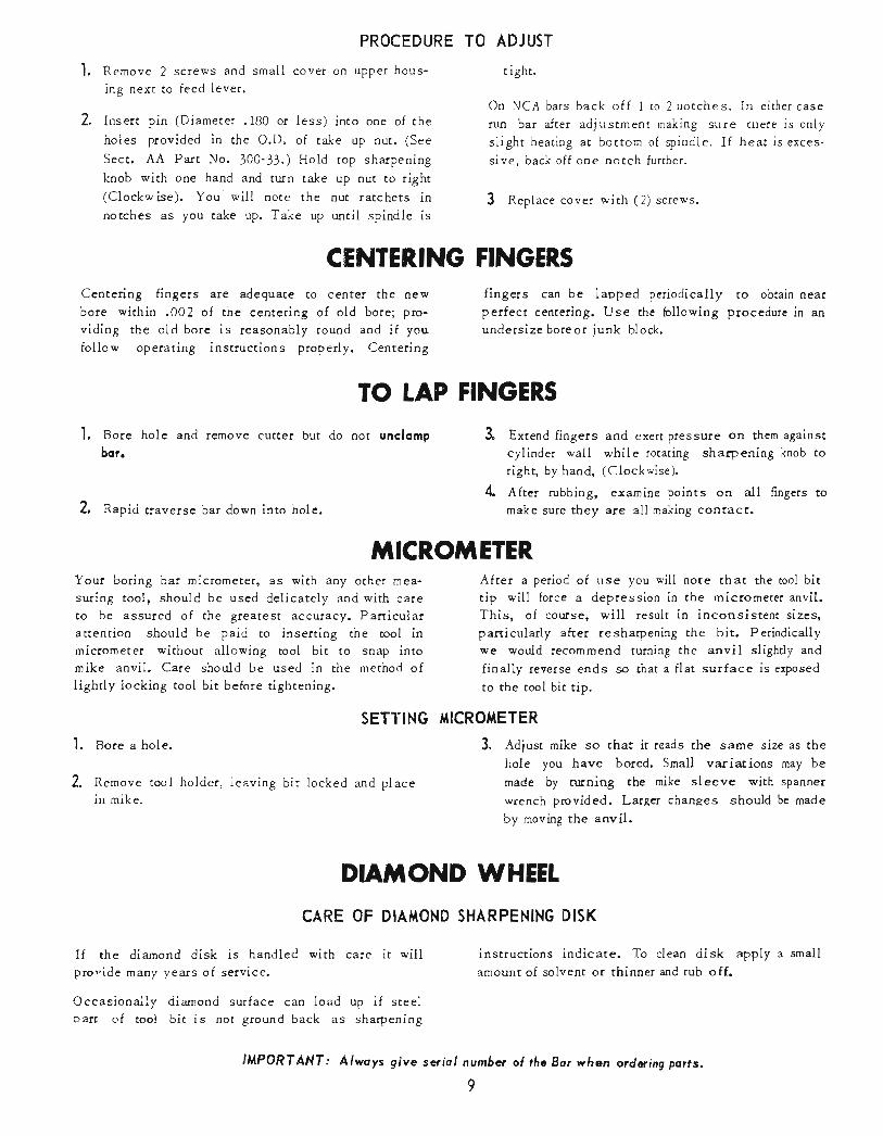
Remove 2 screws and small cover on upper hous'
ing next to feed lever.
2. Insert pin (Diameter .180 or less) into one of the
holes povided in the O.D. of take up nut' (See
Sect. AA Part No. 300-33.) Hold top sharpening
knob with one hand and turn take up nut to right
(Clockw ise). You will note rhe nut ratc hets innotches as you take up. Take up until spindle is
TO ADJUST
tight.
On NCA bars back off I to 2 nocches' In either case
run bar after adj ustment making sure El)ele is only
slight heating at bttom of spindle' If heat is exces-
sive, back off one notch further'
3 Replace cover with (2) screws'
fingers can be lapped periodically to obtain near
pelfect centering. Use the bllowing procedure in an
uodersize boreor iunk block.
TO LAP FINGER,S
I
4
Extend fingers and exert Pressure on them against
cylinder wall while rotating sharpening knob to
right, by hand, (Clockwise).
After rubbing, examine points on all fingers to
make sure they are all making consact'
DN'NOND WHEEL
SHARPENING DISK
instructions indicate. To clean disk apply a small
amount of solvent or thinnet and rub off'
CENTERING FINGERS
Centering fingers are adequate to cenler the new
bore within .002 of the centering of old bore; pro'
viding the old bore is reasonably round and if you
follow oPerating instructions properly' Centering
'1. Bore hole and remove cutter but do not unclomp
bor.
2, Rapid uaverse bar down into hole.
Your boring bar micrometerr as with any other mea-
suring tool, should be used delicately and with care
to be assured of the Sreatest accuracy' Particular
amention should be paid to inserting the tool inmicrometer without allowing tool bit to snap into
mike anvil. Care should be used in the method of
lightly locking tool bit before tightening.
SETTING
l. Bor" a hole.
L Rbmove tool holder, leaving bit locked and place
in mike.
CARE OF DIA}ilOND
If the diamond disk is handled with care it willpro-ide many years of service.
OccasionaiLy diamond surface can load up if steel
parr of tool bit is not ground back as sharpening
tl,lPORTANI : Alwoys give seriol number of the Bor vhen ordaring potts,
9
fiTTROiTETER,After a period of use you will note that the tool bit
tip will force a depression in the micrometer anvil'
This, of course, will result in inconsistent sizes'
particuiarly after resharpening the bic Periodically
we would recommend turning the anvil slightly and
finally reverse ends so that a flat surface is exposed
ro the tool bit tiP.
I{ICROilETER
3. Adjust mike so that it reads the same size as the
hole you have bored. Small variations may be
made by rtrrning the mike sleeve with spanner
wrench provided. Latger changes should be made
by moving the anvil.

OUTER SPINDE ADJUSTMENTALL MODEL
These machines have rapered main spindle bearingheld in a seat by a spring and adiusting nur. Thetension on these bearings is normally adeouate tolast indefinitely under normal boring operarions.
Caution should be used in adjusring chese bearingsin order to avqid a too tight spindle which onlyserves to wear out machine and load down motor.If it should be necessary to adiust bearings, proceedas follows.
The upper bearing is adjusted by turningaluminumcollar at
top of base. By removing (2) screws and lifting feit retainerin order to reach adjusting nut with punch. For NCA barsSer 22100 and later.
Lower bearing is adjusted by removing lower adiust-ing cover and tr:rning adiusting nut with punch. Alsosee below, Lower Bearing Adjustment.
l. Pl.c. and clamp bar over hole or overhang so
spindle can run down. Loosen both adjusting nuts.
On boring bars that do not have clip at side of base, adjust-ment of iower bearing is made at bottom of base.The upper main spindle bearing has a wavy spring underthe take-up nut. The iower bearing has no spring and istherefore extremeiy sensitive to take-up,
Lower bearing take up is located at bottom of base. Re-move lower bearing felt wiper to adjust. Before adjust-ing, back off the Allen lock screw at bottom of base. Pro-ceed with adjustment as outlined previously, adjusting up-per bearing first.
The cutter retraction is actuated by lifting the upperhousing shift lever, which in rurn lifts the centeringrod allowing the back of the tool holder to be raisedby the tool lock spring located under rhe cool holderin dre cucter head cap.
Sbould the ool holder fail to retract we suggest youinspect as folloss.
l. Check to see that the tool holder slor is cleanand iree of dirt.
Z Check for broken tool lock spring in currer head.
3. Run spindle up aod down making sure rhe cen-rering rod raises at least !/16,, when shifr lever
BORING BARS
2. Allo*ing bar to run in feed, tighten lower ad-
iusting nut until you detect a slight drop inmotor RPM.
3. Stop motor leaving bar in feed. Pull down onupper housing by hand. You will note spindlewill drop approximately 1/32" t^king slack ourof fe.,^i. lrrinimum pressure required to pull down
should be ,,it:rout l0 lbs.
Start bar again, leaving in feed, and repeat aboveoperation to adiust upper bearing. Pressure re-quired now to &op spindle should be approximately50 lbs.
Check this spindle tightness at both limits ofspindle travel to make sure that spindle is notexcessively tight at any point.
Early model NCA bars have a 3/B Allen set screw at thelower bearing to provide africtiondrag. This screw must bebacked ofl to adjust bearing and may then be adjusted toadd drag to the spindle movement. Recheck spindle adjust-ment to make sure it is not excessiveiy tight at any partof travel,
Note: An over tight innerspindle adjustment will generateheat at bottom of spindle and resulting expansion rvill makespindie iighi at top of travel.
TOWER BEARING ADJUSTfiTENT
4.
5.
4,
5.
CUTTER, HEAD TOOL RETRACTIONis raised from neutraltering rod does nottlo using. )
!o retum travel. (If cen-raise, see Service Upper
Insert tool holder and raise tool lock lever watch-ing tool to see that it is cocking properly. (Shouldtool fail to cock, recheck for brcken spring anddin in tool holder slot )
if tool holder fails to cock remove (4) cutter headscrews and tap off cutter head. Leave tool holderin and press button checking that tool action isworking properly. Be carefui to replace head so
that tool slot opening is under No. I centeringfinger slot.
,A,{PORTAilf : Alwoys give suial numbet ol the 8q when qdering pqrfs.
t0

NCA tlOTOR CARE ond SERVICE
The NCA type boring bars are equipped with a con-
stant speed, totally enclosed type ball bearing motor,
with a thermal overload. Should the mach.ine become
jammed, the motor circuit will break, but should be
rurnedoffimmediately, as it will attemPt to start again
after thermal overload cools. This overload wiii also
ltrould it be necessary toor lower gear pot from the
manner:
remove the motor housingbar, do so in the following
1. If upp.t housing .is still intact, remove the feed
screw drive pin and unscrew feed screw shaft clearof motor drive shaft, as outlined on Page 7.
2. To remove motor simpiy remove 4 motor studs,which will allow you to lift motor stator assemblyoff of housing.
3. To remove rotor, carefully pry up with 2 screw
&ivers and rotor shaft with driving pinion gear
will come out of gear box.
If furrher disassembly is required, the manual feedhousing (700-13-1) may now be removed from che
base by removrng I hex cap screws. The actuatorscrew assembly, 700-13, may also be removed by
backing out hex actuator screw bearin g, patt #700-1l-1,(see section G-G). It may be necessary, intaking this out to rotate screw shaft slightly to
the right as bearing is removed. (The actuatorscrew bearing may be removed with no other motordisassembly if this shouid be required).
To remove gearing in motor transmission, remove
4 round head screws holding bearing cap (part of700-1 assembly.)
Now, Micarta gear #7AO-22, with high speed gear
700-23. on micarta gear shafr 700-22 may be re-
give seriol numbe+
l1
stop motor .if the continuous loading from a heavy cuttend.s to overheat the motor.
It is important that the motor be kept as clean aspossible,particularly at the cooiiog vent intake andexhaust.
DISASSEfrIBIY ond ASSEIfBLY of NCA MOTOR HOUSING(See Sections B-8, F-F and G-G)
moved, and feed screw gear and shaft #700-24 may
be removed.
The ball bearing 700-11 and 700-15 snap ring may
then be removed out of the 700-J housing.
In order to remove speed change tumbier assembly,(700-6), first remove 700-8-2 speed change retainerbushing. It may be necessary to totate the speedchange knob while removing this bushing.
Now 700-8, speed change control shaft, may beremoved by rotacing counter-clockwise.
Now the 700-6 speed change tumbler assemblymay be removed after snap ring 700-7 is removed.
This process may be reversed to reassemble thisunit. Care must be taken to relubricate the shafc700-24 belween the gear housing bearings, beforereplacement and packing of grease in lower unit.
Set screws may be reset to determine gear backiash of tumbler assembly on reassembly, as shownin section F-F.
When reattaching gear housing 7O0-J to base, caremust be taken to align feed screw properly withupper housing. This rnay be checked by placing a
flat plane across spindle and screw, making sure
::l.tt is in reasonably close contact at four cor-
,MPORIANf: Atuays o{ the Bq wlren ordering por?s.

300- 26TTNUST
300-23THRTBT EEARING
BEARIIIG RETAINER
too - 26DIAMOND WHEEL SIIARPENING KNOE
KNO8, VACUUMBEAR'NG
/_3@ _52BEARINq TAKE-UPSPBING
300-45CENTERINGSTYLE IYITHro0-3PLAIN TYPE
300 - 33SHIFTING LEVER KEY
300 - 34RELEASE LIFT LEVER
roo-tESET COLLAR E
roo - t9WASHER,CENTER ROD,THRUST
roo-t5SHIFTIT.IG LEVER
300-42CENTERINC SHAFTRETAINER
300-33CUTTER SPINDI.EAOJ. NUT A3SY.
300-4€UPPER HOUSING,I-oWER E UPP€,RSACTS. OAVAILABLEIN MATCHEO SETSI
3(}0-22CUTTER SPINOLEORIVE GEAR
E
300-e4FEED NUT
300-36FEED NUT KEYW@DRUFF T9
300-20CLUTCH SI€EVEAND GEAR
300-arCUTTING FE€D GEAR
300-29FEED M',T THrusTWAS}IER
3OO-54 BALL BRG,
3OO-55 THRUST BRG.
3OO.SC OIL SEAL300.RING
300-44GASKET
300-23DRIVE GEAR (KEYeD roFEED SCRaW)
too- 2CENTERING SHAFT
INNER SP]NDLE ASSY,
OUTER SPINDLE AsSY.
roo-20TOOL I-OCK
FEED SCREW
SECTION A -ASHOWN IN NEUTRAL POSITION
300- 3eDRIVE GEAR KEYtwrrx nrver)
To ovoid shipping deloys -IMPORIANT;olwoys give Seriol Number of Bor when ordering ports.
12

roo - 35FELT WIPER700-26UPPER ADJ. NUT100 - 27COMPRESSION SPRINGro0-38 -- \\OUTER 5PINDIE BEARING \700 - 28OUTER SPINDLE I(EY
KEY AND SCREWSHOWN 90" OUTOF POSITION
7oo-s-9 BRG. LaCKNUT
700-|SEARrN6 77-3tO ?
7c,0-25FELT RETAINER \
7OO-12 _SPACER
loo -3E -----
700-t 60 cYcl.t.7OO-2 so CYCLEIIOTOR
- 4bO-3BEARINGI2O2
700-5-+BEARINC CARRIER700-?2MICARTA GEAR SHAFT700-23Ht6H SPEED GEAR-700-2tMICARTA GEAR
704-+STRAIN RELEFCONI{ECTOR
400-1MOTOR CORD
700-3SWIICH
7^^ -<MO'OR GEAR HOUSINGWITH CAP AND RACK7AO- 24 -FEED SCREW GEARAND SHAFT
MOTOR BEARING *2O2voo - t+FELT WASHER
-700 -20MOTOR PINION
7OO-E9 SPACER
roo -35 _
OUTER SPINDLE BEARING
ro0 -37LOWER ADJ. NUT
FELT WIPERiO0 -36
-FELT RETAINER
?oo-to THRU 200-24CENTERING FINGERS
' (uu- I,, SNAP RING 5IOI-II2
SPEED CHANGETUMBLER ASSY,
CUTTER HEAD
too-lCUTTER HEAD CAP WITHTOOL LOCK SPRING
L-
SECTION g-B
loo-t4
-rVACUUM BUTTON
To ovoid shipping deloys -IMPOR TANT: ,olwoys give Seriol Number of Bor when ordering ports.
13

DETAIL D300 - 47FAST DOWN BUTTON ASSY.
sEcTtoN c - c
300-46TRIP LEVER ASSY.cAP SCReW W|TH ljCK l.tuTrLATCH BOLT W|TH NUT,ROCK SPRING
tH? TEVER300i18
SHIFTING LEVERSPRING
DETAIL D
To ovoid shipping deloys -olwoys give Seriol Number of Bor when ordering ports.
IMPOR TANT:
l4

300 -4rSOCKETt/4 - 20
SET SCREWY 1/"
300 - 40SPRING
SECTION E. ESHOWN IN RAPIDRETURN POSITION
300- 37TUMBLER ASSY.
300 - 27UPPER FASTRETURN GEAR
300 - 39PIN
300-36FAST RETURN GEAR SHAFT(wrnr Nur)
To ovoid shipping deloys -IilPORTANT:olwoys give Seriol Number of Bor when ordering ports.

HI6H SPEED GEAR
SPEED CHANGETUMBLER ASSY.INCLUDING IDLERS AND THREADED ROD
SECTION F. F
700-t3-4 -MANUAL FEED HANDLE
\
)
700-8SPEED CHANGECONTROL SHAFTAND RETAINER
FEED SCREWDRIVE GEAR
SHAFT
TUMBLER STOP SCRTWS
700 -t3-lMANUAL FEEDHOUSING
MOTOR GEARHOUS}NG RACK
700-t3-3ACTUATOR SCREWBEARING
700-t3-2ACTUATOR SCREW SHAFTAND CONE WITHWASHER AND COLLAR
SECTION G_G
To ovoid shipping deloys -olwoys give Seriol Number of Bor when ordering ports.
l6
IMPORTANT: