hly ROTTLER · ROTTLER MANUFACTURING HP3A ... Gear Box Section. ...5.11- ... Upper Limit Valve ---...
87
hly 27,1994 ROTTLER MANUFACTURING HP3A HONING MACHINE MACHINE SERIAL NUMBER OPERATIONS AND MAINTENANCE MANUAL MANUFACTURED BY: ROTTLER MANUFACTURING COMPANY 8029 South 200th Street Kent Washington 98032 USA Phone: (253) 872-7050 Fax: (253) 395-0230 NOTE: WHEN ORDERING REPLACEMENT PARTS, PLEASE GIVE THE MODEL AND SERIAL NUMBER. ORDER BY PART NUMBER. THERE IS A MINIMUM ORDER OF $25.00
Transcript of hly ROTTLER · ROTTLER MANUFACTURING HP3A ... Gear Box Section. ...5.11- ... Upper Limit Valve ---...
hly 27,1994
ROTTLERMANUFACTURING
HP3A
HONING MACHINE
MACHINE SERIAL NUMBER
OPERATIONS AND MAINTENANCEMANUAL
MANUFACTURED BY:
ROTTLER MANUFACTURING COMPANY8029 South 200th Street
Kent Washington 98032 USAPhone: (253) 872-7050Fax: (253) 395-0230
NOTE: WHEN ORDERING REPLACEMENT PARTS,PLEASE GIVE THE MODEL AND SERIAL NUMBER.
ORDER BY PART NUMBER.
THERE IS A MINIMUM ORDER OF $25.00

CO\TTEbrIrSTNTRODUCTTON/SAFETY/TNSTALLATTON ....... 1IntroductionlDescription . 1.1Linited Warranty
Safetyfnformation. .L.2Machine fnstallation .....1.3Air Supply .. ... r.4Power Supply ... I.4Electrical Hook-up fllustration ....1.5CONTROLS ...... 2Park position Linit Switch .... 2.LCoolant Toggle Switch .... 2.LStart push Button or program Start .2.LStop Push Button or proqrarn Finish ... ... 2.IStroking Toggle Switch ... Z.IStrokes per Feed .... 2.2Total Feed ..... 2.2Program rON, Light .. 2.2Progrm Start/Clear. .2.2Manual Feed/program Hold .2.2Stroking Speed Control ... 2.2Short Stroking Bottorn Dwell . . . 2.3Clarnp Float Button .. 2.3Feed Up (Stone pressure) ... ... 2.3Hone Motor Shutoff Delay .2.3Control_ Illustration ..... 2.4Pendant Tllustration ..... 2.5
OPERATING INSTRUCTTONS ....... 3Honi-ng in General .. .3.1fmportant Facts ..... 3.2Stone and Guide Instal_Iation . . 3.3Honing procedures .. . 3.4Block Loading .... 3.4Hone Head positioning. .....3.4
:ii:i;.,ffi:ii:ff;.::.:. : . :: : : : : ::: :: : : : : :.:: : : : : . : : . : :Machine fnstallationAir Supply ..fgwer luppryElectrical Hook-up fllustration
Lower Travel Linit Setting .3.4Upper Travel Linit Setting 3.5Feed Setting .""..3.5Program Start .... 3.5Hone Cycle .. 3.5Feed Indicator Ring .,...Load MeterDwell Button Short StrokeChecking The Size of The BoreHone Cyc1e CompteteFinish PlateauManual StrokingLirnited Over Travel and Blind HolesStroke Cycles per Minute ..
3.53.63.63.63.63.63.63.63.73,7Auto Feed Stop Feature

MAINTENANCE . ....... 4
Lubrication . ... 4.tLubrication Illustration ..,4.3
Hydraulic System .... 4.4System Checking .. 4.4System Bleeding .. 4.4Bleeding Illustration . 4.6
V-Belt Adjustrnent/Remova1 .. ...4.7Gear Box Removal . ... 4.8Gear Box Disassembly .. '.. 4.8Float/Ctamp . -., 4-LOUpper/Lower Limit Val-ve Adjustnent.. ....A-LL
MACHINE PARTS BREAKDOWN ... ... 5Front/Right Side View .--- 5-1Wiring Diagram Pendant ... 5.2Wiring Diagram Machine ... 5-3Schernatic Diagrram... ...--5-4PneumaticCircuitDi-agram... ..5.5Electrical Power Supply Panel - 5-6Control Panel .. 5.7Carriage - - 5.8Front Section Rocker Arm . ..... 5-9Drive Pinion Assembly .--- 5-l-OGear Box Section. ...5.11-Carriage Float/Clamp. .---5-L2Stroking Control- Air. ---- 5.13Interface Sensor AssemblY 5-L4Ratchet Actuator Assemb1Y 5-15Stroking Cytinder --- 5-16Lo$rer Travel Limit Stop Lever - 5-L7Upper Limit Valve --- 5-18Upper Pivot Lock/Motor - Safety Switch -. 5-19Pneumatic Power SupPlY -. - 5-24Splash Tank Coolant Systen . -. - 5.2LBlock HoId Down Fixture Assembly - - - 5-22optional Bl-ock Hold Down Clamp Assenbly - 5-23Optionalv-7L Fixture ----5-24Optional Stone Depth Assembly - 5-25
Stone Depth Assemb1Y Set-uP 5-26
TOOLTNG ....---6Standard Hone Head Assembly - - - 6'1optional Junior Hone Head Assernbly - 6.2Optional Minor Hone Head Assembly -- 6.3Stone and Guide Sets (Standard Hone Head) . - - - 6-4Stone and Guide Sets (Junior Hone Head) .,. - - - 6-7Stone and Guide Sets (Minor Hone Head) ... . -. - 6-8Precision Hone Head - 6-9
Stone Holder - Sleeve Sets - 6-10Stone Sets .. 6.LLDisassembly Instructions -.. 6-L2
OLD STYLE PARTS ASSEMBLIES .. ...... 7
MATERIAL SAFETY BULLETIN ..... 8

I ntroduction/Safety/ Instal lation Page 1.1 HP3A Machine
r }\TTR,ODIJCIT I OI\rThis manual- is divided intochapters as l-isted in thetabl-e of contents.
It is required that the ner^ruser of the HP3A honingmachine read this manual. paycl-ose attention to the chapterconcerning safety.
DESCRIPTION
The model HP3A Honinq Machineis a wet, complete cylinderblock and general purposehoning machine. Hone rotalingpohrer is supplied by a totatlyenclosed AC motor driving abelt and gear reduction afivemounted within a rocker armarrangement. The honing headis driven through a universaljoint.
An air cylinder with a hy-draulic check system providesstroking power. Stroking mayal-so be manually operated.
The support carriage is airfloated and clamped to providesirnple and easy hole-to-ho1esetup.
Convenient devices areprovided to property controlhoning operations and provideeasy handling.
A rrvrt f ixture is provided,which efficiently holds Y-6,V-8, and in-line blocks forhoni-ng. Optional clamps areavailable to clamp most anykind of in-Iine block orsirnilar workpiece.
A splash tank is l-ocatedwithin the main frame and acoolant punp tank is locatedunder the machine. A switch isprovided on the control- panelto operate the coolant system.
I-I}lIITEDV{rAR-R-AI\TT:'
Rottler Manufacturing Companymodel HP3A parts and equipmentare warranted as to materialsand workmanship. This linitedwarranty remains in effect for
erated and maintained as peri nstructi on i n th i s manua'l -
Standard air and el-ectric com-ponents are warranted by theirrespective manufacturers(NOTE: their i-ndividual- war-ranty periods may vary signif-icantly from Rottl-er manufac-turing poticy).Tools proven defective withinthe warranty period will- berepaired or replaced, dt thefactory's option.We accept no responsibilityfor defects caused by externaldamage, wear, abuse, of rnis-use, nor do we accept anyobligati-on to provide compen-sation for other direct or in-direct costs i-n connectionwith cases covered by the brar-ranty.Freight charges on warrantyitems (non-air shipment only)will be paid by RottlerManufacturing for a period of60 days only from date of in-stallation or set-up by a

Inffoduction/Safetyllnstallation Page 1.2 HP3A ttachine
qualified service technicianor sales rep.
Freight charges after the 60day period are the customersresponsibility.
SAFEITT'II\TFOR}IIAT I O}.it
CAUTION:This machine is capable of
causing severe bodily injury.
As with all machine tool-s eyeprotection must be worn at aIItimes by the operator or otherpersonnel within the area ofthe machine.
In particular the operatorshoul-d be very cautious of thehone head area.
The operator and nearbypersonnel should be farniliarwith the location andoperation of the stop button.ELECTRICAL POWER Make sureall electrical equipment hasthe proper electrical overloadprotection,
ITTACHINE OPERATOR - Operator ofthis HP3A Honing machineshould be a skilled machinistcraftsman: that is, wellversed in the caution I careland knowledge required tosafely operate a metal cuttingtool.If the operator is not askilled machinist, theoperator must pay strictattention to the operati-ngprocedure outlined in thismanual, and must getinstruction from a qualifiedrnachinist in both theproductive and safe operationof this HP3A Honing Machine.
Rottler HP3A Honing equipmenthas the following areas ofexposed moving parts that youmust train yourself to respectand stay away from when theyare in motion:
1-. I{ORK CLAIIPING be surework is clamped securely inaccordance with theinstructions.
2. L,OIiTER STOP Set loWerlinit carefully so thatwebs or other obstructions,in the bore, do notinterfere with the guidesor stones.
3. HONE HEAD AREA - Keep handscompletely ahray f rom therotating honing head at ALLtimes.
4. POWER STROKING DO NOtoperate power strokingwithout upper travel limitlever }ocked,
5. OPERATOR COIflIROLS Famil-i.arize yourself with theexact location of the stopbutton so you can immedi-ately react to an emer-gency.
6. I.IOllfNG -_Do not enqagerotation power when honehead is out of a cylinder.
REI,{EIiBERMeta1 cutting tools have thespeed and torque to severelyinjure any part of the humanbody exposed to thern.

Introduction/ S afety / Installation Page 1.3 [P3A l,lachine
}ltACI{I }TEI hTSTAI-I-A:tr I C)}.{
IOCATION
The productivity of this ma-chine wiII depend to a greatextent on it's proper initialinstallation, particularly themeans by which cylinder blocksare lifted into the rnachine aswell- as the material handlingto and from other operationsin your shop.
The proper loading arrangementand location for your HP3A rna-chine is extremely important.
A slow travel (6' to 1o'/min)power hoist, operated fromeitfrer a bridge crane or a jibcrane arrangement works veryweII. A 1000-1b hoist isgenerally adequate for li-ftingthe engine block. An air hoistwith speed control makes anideal rnethod f or f ast,convenient loading.
If some production honing withthis machine is anticipated,and the cylinder blocks arenot directly loaded andunloaded from a conveyor, w€r'rouId recommend considerableattention be given to thecrane so that it covers an ad-equate area to allow the oper-ator to back up and removecylinder blocks without clut-tering up his own area. ff twomachines are to be operated bYone operator, w€ would recom-mend that the open faces beplaced at right angles to eachother, with the machines aP-proximately three feet apart.
t'NPACKING
CarefulIy uncrate the HP3AMachine. Remove all equiPrnentin splash tank excePt the rrvrr
fixture frame.
Cornpletely clean thesearticles as well as themachine's upper table withsotvent, also clean the lowertravel limit stop rods. Rustinhibitor is apPlied to themachine at the tine ofshipment and must be removedbefore operating the machine.
SHIPPING HOI.D IpWN BOLT(refer to illustration on Page5.10)
The Hone carriage is shiPPedwith the hold-down sYstemlocked. This system must beunlocked. Remove the cover(514-3-3D). Remove the cotterpin in the hex nut. Loosen thenut all the !'IaY. Tighten thenut back down with just Yourfingers. Loosen the nut I/4turn. Insert cotter Pin.LEVELIilG
Four cap screws and jan nutsare provided with the machinefor leveling. Insert thescrelrts from the bottom of thebase. Place the jam nuts ontop of the threaded hole inthe base.
Using a precision leve}, Ievelthe upper table within .002r1per tbbt in both directionsluxcept favor the high settingto the front for best coolantreturn).

Introduction/Safety /Installation Page 1.4 IIP3A Machine
AIR, STJPPI-I'
The HP3A machine requires 5.7cubic f eet/rninute at 100P.S.I. compressed air (aminimum 1 HP air compressoroutput).
Attach air supply to thefilter regulator on the rightside of the splash tank, Pushand hold the float clamPbutton located on the front ofthe carriage. While holdingthe push button adjust the airregulator to 100 P.s. i.(tocated on the right side ofthe splash tank). (Pushregulator knob down to set,pull up to lock).
bfoirE:To assure a long service lifefor your HP3A machine the airsupply must be moisture free.If there is any doubts aboutthe air supply install a watertrap.
POvirER" S{JPPI-\Z
Disconnect a1l Power beforeservicing this machine.
This nrachine requires 2O8/23Ovolt AC three Phase. (seewiring diagram page 5.2 & 5.4)
Electrically connect inaccordance with the NationalElectrical Code and Your localcodes. Note: this machinerequires the use of anelectrical disconnect swi-tch.
Attach three phase wiring tothe L1 , L2, L3 terminal on toPof the hone motor starter-(see hook up illustrati-on Page1.5).
CAI.TT I OI{ :fhis machine cannot be run on44O vo1ts. A transformer mustbe installed if 440 volts mustbe used.
Turn the stroke toggle switchon the control Panel to \OFF' -
Pull the hone rocker arm downinto its operating range totest run.
Push start button, check honehead rotation. The hone headshould turn clockwise lookingfrom the top. Exchange 2 wireson the Ll, L2, L3 terminal onthe motor starter, to changerotation.
Attach hone head assemblY-
COOLANT PUMP SYSTEM
Pour a maximum 30 Gall-ons ofhoning oil into sPlash tank(Mobil Met 33 or UPsilon orany equivalent fight honingoi1. )

I ntrotlucl i on/ S a t'etyi I nstallat ion L,lectrical Flook-up I'age 1.5 [P3A ]lachine
ELECTRICAL2JO VOLTS J PHASE60 HERTZ
IMPORTANTELECTRICALLY CONNECTIN ACCORDANCE WTI-INA IIONAI. ELECIRICALCODE AND YOUR LOCALCODES
I.IONE MOTOR
STARTER
-----GtiEEN WRE
Lr L2 LJ
FOR ''FI'' T)'PE
HEATER ELEMENTSSEE BACK OF
MOTOR STARlERENCLOSURE COVER
IO CAtlRIAGE
TO CONTROLPANEL


Confrols Page 2.1 nPla Hachine
hausts ttrol line.The following information
describes the sequence ofcontrol actions.
PARK POSITION LIUIT SWITCH
An electrical lirnit switch islocated on the carriage underthe rocker arm pivot. Thisnormally open switch is closedby a cam when the rocker armis lowered into its workingrange. When cfosed it allowsthe air control solenoid valveand the motor starter to beenergized. When open it droPsout the electrical controlcircuit.COOI"ANT TOGGLE SWITCH
The cool-ant swi,tch is locatedon the pendant control Panel.This switch turns on and offthe coolant puiltp motor. TheIever on the left side of thecarriage, r€gulates thecoolant flow.
START PUSH BIIflTON OR PROGRAUSTART
Press start button to closecontacts on motor starter.This energrizes the motor,which in turn Provides rota-tional power to the hone head,through a V-belt and a qearreduciion. It also energizes asolenoid val-ve. This opens toprovide air pressure, from theupper limit valve, which ismechanically held open bY aplunger on the end of the Pis:ton rod, to shift the sPool ofthe stroking valve.
The stroking valve allows airpressure to flow to the gPPerpart of the lower cYlinderdriving its piston and therocker arm down. As the Pi-stonrod moves away from the upperlimit valve, it closes and ex-
The upper pivot of the rockerarm Continues down until itsactuating screw strikes thelower lirnit va1ve. Which opensand aflows air to flow to theopposite air pilot Port of thereciprocating valve.
This ai-r Pilot shifts thespool of the reciProcatingvalve, Which exhausts the airfrom the uPper Port of thelower cylinder and allows airpressure to flow to the bottomport of the lower cYlinder,driving the Piston and rockerarm up.
As the actuating screw movesabray from the - Iower linitvalve, it closes and exhaustsai-r from this control 1ine.
STOP PUSH BTIPTON OR PROGRAUFINISII
Press stop button to oPen con-tacts of the motor starter tostop rotation of the motor- Italso opens the electrical cir-cuit to the solenoid valvecausing it to cl-ose and ex-haust the air from its tube tothe upper linit valve.
Stroking will- stoP at the toPof the up stroke and the sPoolof the reciprocating val-vewill remain ih this Positionwith air pressure in the bot-tom of the lower cYlinder un-til start button is Pressed.
STROKING TOGGLE SWITCH
The stroking toggle switch islocated on the right center ofthe control Panel. When thisswitch is turned off it opensthe circuit to the solenoidva1ve, which stoPs the Powerstroking.

Confrols Page 2.2 [P3A uachine
STROKES PER FEED
This switch is used to programthe number of strokes betweenstone feed increases. Togglethe switch up to increase thenumber of strokes. Toggle theswitch down to decrease thenumber of strokes. As youincrease and decrease thenumber of strokes you will-notice the number in the abovedisplay. The 2 digits on theIeft of the display show thenumber of strokes betweenstone feed increases. The 2digits on the right side ofthe display will count theactual strokes as the machineis running.
TOTAL FEED
This switch is used to programthe number of times themachine will repeat thestrokes per f eed progiram(described above). Togg1e theswitch up to increase thenumber. Toggle the switch downto decrease the number. The 2digits on the Left, in theabove display show how manycycles you programmed. The 2digits on the right record howmany cycles the machine hascompleted.
PROGRAU TON' TIGHT
The light comes on when aprogram has been activated,the program does not actuallYstart until the start buttonis pressed.
PROGRAI,I START/CLEAR
Togg1e this switch uP toactivate a program. Theprogram light comes on. WhenLne start button is pressedthe machine witl start runningthe program represented bY the2 digital readouts.
Toggle this switch down toclear the program. The Programstays as displayed on thedigital readouts but theprogram light goes out and theprogram wontt run.
UANUAL FEED/PROGRAI,I HOLD
Togg1e this switch uP and holdit, for manual feed. EverYtime the rocker arm hits thebottom of its stroke thestones feed out one click.Release the switch and theprogram resumes.
Toggle this switch down andhold it for program ho1d. Thisstops feed outs of the stones,while the stroking continues.Release the switch to resumeprogram as normal.
STROKING SPEED CONTR.OL
The upper cylinder of the armprovides smooth control of thestroking motion and strokingspeed control. Thiq hYdrauliccylinder punps liquid back andforth through a ball valve,which is located on the rightside of the carriage.
By opening and closing thisvalve, stroking sPeed can bechanged. A reservoir is 1o-cated on the carriage underthe rocker arm Pivot, Thisreservoir compensates for vol-ume change due to temPeraturevariations.The reservoirs Iiquid is fedthrough a flow control valve,Iocated on top of the ballvalve. This valve can beopened for bleeding and re-fitling.A regulator is located on backof the carriage to regulate

Controls Page 2.3 HP3A I'lachine
the air pressure (15 PSi) tothe reservoir.SHORT STROKING BOTTOI,T DIVEtt
A check valve is attached tothe stroking valve between itand the upper lirnit valve. Ajurnp air line is routed aroundthe check valve and a Pushbutton control valve is Io-cated on this line.When this push button controlval-ve is pressed air can getthru the check valve onIY'then it is traPPed in the airline. This keePs the sPool inthe stroking valve shifted todown stroke onIY.
Then the lower limit valve isactuated. Its higher Pressureshifts the sPool in thestroking valve to uP. stroke,but as soon as the Pivot armmoves a$ray from Iimit valveand exhausts its air, the airtrapped in the other controlIine- causes the sPoo1 to shiftto down stroke again.
CI,AITP FLOAT BIITTON
Press CIarnP/FIoat button tofloat carriage. This allowsair to flow through valve toregulator, then out two Portsof-the regulator. Air from oneport f lows through the f igf-ttbrifice on the bottom of thefloat plate. Air from theother port flows through aflow control valve then to theleft side of the float Plateand out the orifice on thebottom of the float Plate.
FEED UP (STONE PRESSI}RE)
The nanual feed uP switch (orthe program relaY) sends asignai t5 tne feed-uP.solenoidvaive. The valve shifts airpressure to the engagementiiae of the feed uP cYlinder.The piston of the cYlindermoves the sPool. This Pivotsthe ratchet into engagementwith the ratchet wheel- Theratchet pawl then rotates thewheel one tooth.
When the solenoid valve is de-energized it moves the airoresiure to the retract side-"t the cylinder. The Pistonretracts the Pawl, then re-turns the sPool to its origi-nal position.
}trOTE :Interface sensor must be actu-ated for feed uP.
HONE I{OTOR SHUTOFF DEI,AY
At the end of an automatichoning cYc1e, the hone headwitl stoP rotating before theIast strbke is comPlete- Thiswill result in the machine,dragging a non-turni-ng honen".d- i; the cYlinder- Thisknob can be adjusted so thehone head wil-I continue to ro-tate until it reaches the topof the last stroke-

Controls Control Illustration Page 2.4 EP3A Machine
F6tlJ unI<Li LrlFl<LrM.E
oz-):<J-L!Y=+^FUaPPOFIOa6
L
Ja)\zFO<F/iFY:LL(D
Oez6Fr-OOH-lL=
JotFz
ZvVoO[ltrt!FO-aa
JLrJEO
Fe?z>r)'ObJ-=-2.=iloZET
azai6nrlLl-Z-
=H?Pu Ea.2tr>< 5 i,r t'-ILLtrO
ot!LtlL-
6oo
Ir@
@zBd
E.F<LL
\ \- Llln/DJ :=-' / 4 z '\/ < <"6/ <L)<>/ e
-(JLrl\ i62n\ oo<m<\r \
()z
E:aooolL'7 t-
I*i-nz.l'lo?
5tr=-:z a z.<o<Io->
Ld
)F<z.>!=59Ot!
JotFzO
o_oFat-
=:
)LrJ
EFv.trJ
=o)
o_oFaF
==
JUJ
EF-
Ettio-o_l

oNNoo
INUzIb€
Controls
DIGITAL RIAD OUISETTING SWITCHES
'*.*-ot. Iorcnrnsr I
HONE MOTORSHUTOFF DELAYKNOB
Pendant Illusffation
ACTUALCOUNTED
CCNTRCL PANELIDENTIFICATION
Page 2.5 HP3A Macbine
DIGITAL READ OUT
NUMBER OFSTROKE CYCLESPER iUINUTE
ACTUALCOUNTED
LOAD I,IETER
(rNDrcATEs sToNEPRESSURT, TAPER,& OUT Or ROUttO)
TROKING SWITCH(TURN oFF
STRoKTNG oNLY)
COOLANISWITCH
STOP BUTTON
BU ITONSTART
MANUAL FEED(ADVANCES FEED
wrrHour PRoGRAM)
PROGRAM HOLD(HoNrNG coNTtNUtsWITHOUT ADVANCINGPROGRAM)
PUMP
PROGRAM"oN"(LtGHT) +-
i-PROGRAM
"O*'-{PRoGRAM cr-rnn-i
(RETURN PROGRAM ITO STARTINGPOrNr)
STROKES BETWEENFEED INCREASES
FEED INCREASES(.001 PER NUMBER)

Operating lnstructions Page 3.1 nple Machine
OPERA.TIbTG
$oNrNG rN GENERAT
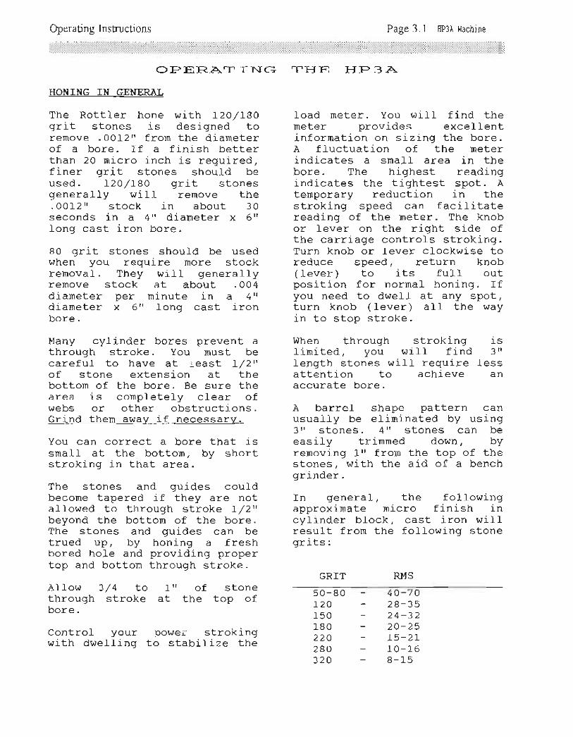
The Rottler hone with L2Ol78Ogrit stones is designed toremove .001-2rr from the diameterof a bore. ff a finish betterthan 20 mj-cro inch is required,finer grit stones should beused. 72O/LBA grit stonesgenerally will remove the. OOl-2tr stock in about 30seconds in a 4tt diameter x 6rrlong cast iron bore.
80 grit stones should be usedwhen you require more stockremoval. They will- generallyremove stock at about .OO4diameter per minute in a Attdiameter x 6rr long cast ironbore.
Many cylinder bores prevent athrough stroke. You must becareful to have at least I/2t'of stone extension at thebottom of the bore. Be sure thearea is completely clear ofwebs or other obstructions.Grind them awav if necessarv.
You can correct a bore that issmall at the bottom, by shortstroking in that area.
The stones and guides couldbecome tapered if they are notallowed to through stroke a/2"beyond the bottom of the bore.The stones and gui-des can betrued up, by honing a freshbored hole and providing propertop and bottom through stroke.
Allow 3 / 4 to 1rr of stonethrough stroke at the top ofbore.
Control your power strokingwith dwelling to stabilize the
THE HP3A
load meter. You will find therneter provides excellentinformation on sizing the bore.A fluctuation of the meterindicates a small area in thebore. The highest readingj-ndicates the tightest spot. Atemporary reduction in thestroking speed can facilitatereadi-ng of the meter. The knobor l-ever on the right side ofthe carriage controls stroking.Turn knob or lever clockwise toreduce speed, return knob(lever) to its fufl outposition for normal honing. Ifyou need to dwell at any spot,turn knob (lever) all the wayin to stop stroke.
When through stroking isIimited, you wiII f ind 3 'rlength stones will require lessattention to achieve anaccurate bore.
A barrel shape pattern canusually be elirninated by using3 tr stones . 4tt stones can beeasily trimmed down, byremoving l-rt from the top of thestones, with the aid of a benchgrinder.
In general, the followingapproximaLe micro finish incylinder block, cast iron willresult from the following stonegrits:
GRTT RMS
50-80L20150180224280320
40-7428-3524-3220-2515-2410-168-15

Operating Instructions Page 3.2 HP3A Machine
I}IIPORTA.}TT FA.CTS
The hone head will sometimeschatter or squeal when thestones r^rear down. This problemis caused by too much pressureon the guides. To correct thisproblern, remove the guides anddress them as shown in thesketch below.
The heat generated in honingwill expand the bore diameterbeyond its room temperaturesize, with more expansion inthe thin wal1 mid-section.Expect approximately a .0005''reduction in size after coolingto room temperature.

Operating Instructions Page 3.3 HP3A Machine
STOI\TE Ab{D G{JIDE IhTSITAI,I-ATIOb{
To install new stones:Lift inner adjusting shaft, androtate clockwi-se to latch.Pivot hone head 90 degrees(horizontal) so that pinion canbe removed.
NOTE:Stones and guides will fall outwhen adjusting pinion isremoved and head is pivoted 90degrees.
Insert stones and guides intoholes marked with 1X'. The rackteeth must face the center ofhone head.
INNER ADJUSTINGSHAFT _ LIFTAND ROTATECLOCKWISE TOLA'CH
CLEAN GEARSAND LIGHTLYGRTASE MONTHLY
PULLPINION OUT
While holding stones and guidesin, pivot hone head 90 degrees(Horizontat) . Insert adjustingpinion into head and pivot thehead back to the verticalposition, Unlatch and lower theinner adjusting shaft into itsposition in the pinion.
NOITE :Used stones and guides that areto be reused must be kept insets.
NSERT IN HOLTSrtxrt
MARKTD
PIVOT
L,I3
f.-
\t >)
1
HEAD UP

Operating Instructions Page 3.4 HP3A Machine
HONTI}\TG PR-OCEDIJR.ES
BLQCK LOADTNG
Block hold down fixture can beused for inline, tV'n and \Y'blocks.
Move hone carri-age to the f arright of the maj-n base.
Place block supports ontocradle with key engaged intoslot (see page 5.20). Placesupports on edge for blockswith exposed main bearing caps.Place supports flat for blockswith main bearing caps recessedabove the pan rail.
}trOTE :Main bearing cap must be rroNtt.
Place clamp bar thru mainbearings of block.
Rotate clamp screw out of theway.
Lower the block into thefixture. Align the clamp barwith the front clamp bar guideson the cradle ends. Pull theblock toward you after the barengages the front quides. Theclamp bar will rotate into itsclamping position. A1low theclamp bar to slide down theseguides as the bl-ock is lowered.
Rotate clanp screws forward andclamp the bar evenly.
HONE HEAD POSITIONING
Press float button to float thehone carriaqe. Position honehead over the first hole.Release float button to clamp.
LOWER TRAVEL I,IUIT SETTING
Expand or contract the stoneassembly to the approximatebore size. To expand turnhandwheel counter cl-ockwise. To
contract pu11 and turnratchet feed release, turnhandwheel clockwise.
Sometimes it is necessary toexpand or contract the stoneassembly a large distance. Liftinner adjusting shaft at honehead and rotate clockwi-se tiflit is latched. Lift adjustingpinion of hone head off of it'sgear and rotate pinion toexpand or contract stones.
Be sure to reengage the qlear ofcentering pinion. Lift and turninner adjusting shaft countercl-ockwise to unlatch.
Check for possible j-nterferencepoints in the }ower part of allcylinders. Release both upperand lower stop levers. Lowerhone head into a cylinder andposition at lowest point ofstroke.
}[OTE :Stones and guides should haveapproximately 3/4" throughstroke. ff tbere isinterference the over travefcan be reduced.
At this position expand stoneslightty against cylinder wallsto hold rocker arm. Raise thelower stop until it rests onthe rocker arm, then clamp it.
Lower travel linit setting wil-Inot have to be changed in thisblock unless there is anobstruction in one of the othercylinders.
CAI.JTIO T :If hone head crashes into a webor obstruction the pinion willtwist or break. This conditionj-s not covered by warranty.

Operating Instructions Page 3.5 HP3A Machine
UPPER TRAVEL LIUIT SETTING
Release stone pressure bYpulling and turning ratchetfeed release, then turn handwheel clockwise. Raise honehead until stones extend aboutlrr out of the top of the block.Lock upper stroke linit. Do notover tighten upper stop limitc1amp.
FEED SETTINGSet strokes required betweenstone feed increases. Setnumber of stroke/feed cycles.
The following honing examPleswere taken in a GMC block witha 4tt diameter bore and a 5-7 /8nIength of bore. These resultswil-t vary with stone hardness,honed material- etc.
Finish honing, .OOZ diameterstock removal, 180 grit stonesin a cast iron block. Strokeswere set to 9 and total feed toL7.
Rough honing, Stock removal-, 8Ogrit stones irr a cast ironblock. Strokes \^Iere set to 9and total feed to T7.
PROGRAU START
Once the program is set-uP,toqgle the program start switchup. This activates the Program.Press start button.
HONE CYCLE
Turn stroke switch on control-panel to roN' position.
Turn coolant toggle switch oncontrol panel to tON' position.
Press the start button.
Remember: the lirnit switch inthe rocker arm will not a]lowthe motor to operate when thehone head is in park Position.
Turn handwheel counterclockwise, with ratchetengaged. Bring load uP to 80 to1-00? on rneter.
If you go over 100? You canrelease pressure by pulling andholding ratchet feed releaseknob, then turning handwheelclockwise.
FEED INDICATOR RTNG
Each mark on the feed ringrepresents .OO1 of the diameterof the bore. Each ratchet clickalso represents .O01 on thediameter. Turn thefeed ring to to', after stonesare brought up to honing foad.As the load on the load meterdrops, keep stone Pressure uPby turning handwheel counterclockwise. The movement of thero' mark on the feed ring awayfrom the index mark on the gearbox vrill give you an indicationof how much stock You haveremoved.
Due to stone break down it witlbe somewhat less than indicatedby the feed ring.
hTOiFE :Using with optionalhone head (see Page
mark on feed ringratchet advance isdianeter.
prec]-sr-on6.9) each
and each. OOO3 on
LOAD I.{ETER
Note load on load meter as themachine is stroking. A largeswing of the needle indicates asmall area in cYlinder. Thesmall area being the hiqhestreading, usually at the bottomof the cylinder. Dwell in thisarea to open it uP, thencontinue stroking.-A temPorarYreduction in the stroking sPeed

Operating Instructions
::::::::::::::::::::::::::::::::::::;l;i;i;i;l;l1l;l;l;l;l;i;i;l;i'lilii;ii;i;l;i;i.
can facititate reading of themeter. The knob or lever on theright side of the carriaqecontrols stroking speed. Turnclockwise to reduce speed,return to full out position fornormal honing.
pt{ELL BTITTON (SHORT STROKE)
Push dwell button on rj-ght sideof carriaqe. Hone will shortstroke at the bottom of stroke.Press button on up stroke orthe first 2oZ of down stroke atnormal- stroking speed. NOTE: Ifdwell button is pushed duringthe lower part of stroke (orany part of down stroke ifstroking at slow steed) thedwell may be slow, long, orpossibly stall mid-stroke.NOTE: ff the bottom over travelis less than L/2" lower dwell(short stroke) early in thecyc1e.
The length of short stroke canbe reduced by reducing thestroking speed. To dwell at thetop of the stroke turn strokingswitch off.
CHECKING TIIE SIZE OF TIIE BORE
To check bore size, firstreduce stone pressure. Pressthe stop button. Place lefthand on rocker arm handle.Release upper travel lirnitIever. Move hone head out ofthe way. After checking size,reset upper travel l-imit 1ever,press start button and bringIoad up with the handwheel.
HONE CYCLE COUPLETE
After the bore is finished,reduce the stone pressure'Press the stop button, themachine will stop at the toP ofthe stroke. Release the stonepressure fulty. Place left handon rocker arm handle releaseupper travel linit lever. Press
float button to float and moveto next cylinder.
FINISH PI,ATEAU
If a plateau is required afterbore is brought to size, con-tinue honinq f or approxirnatelY6 to 10 strokes at a 2OZreduction in stone pressure.
II{ANUAL STROKING
To hand pump rocker arm, turnthe stroke toggle switch on thecontrol panel to \OFF'position. Release upper travelIimit lever. AIl functions wiIIoperate with exception of thepower stroking. Use stoP buttonto stop hone.
Do not operate power strokingwithout upper travel linitlever locked. If You startmachine with power stroking onand lever unlocked, the Pistonwill go to the bottom of thestroke and remain there.
To return it, Press the stoPbutton. Check to make sureupper travel limit lever iscompletely unlocked. KeeP Yourhands weII clear of aIImechanisms.
Manually bring the rocker armdown to the lower stoP or use apencil or screwdriver todepress the Iower limit valveand the cylinder wlll return tothe top.
LI}IITED OVER TRAVEL AND BLINDHOLES
A problem with stock removalwith hone heads exists on theCheverolet 350 block. There isa maximum over-stroke at thebottom of 3/S to 7/16 and anoften hlorse condition createdby a remnant pad at the bottornthat extends about 1/4" beYondthe main bore.
Page 3.6 HP3A Machine

Operating Insfructions Page 3.7 HP3A l{achine
The heavy-duty head loses L/8"of the over-travel with thestone jacket rnaking thesituation more difficul-t.
If the lower remnant padsrequire stock removal-, there isalmost no way to hone properlywithout using a die grinder,portable grinder, or a boringbar to relieve the pads.
In order to achieve the bestpossible bore that is nearblind (that is without relief)HP hones may be dwell-ed at thebottom with the stroke speedcontrol. Stone lengths may beshortened to 2-L/2tr or 2-7/4nby cutting off at the top end.It may be necessary tooccasionally redress stones ina bore with mini-mum of 1tt overtravel at the bottom of bore.
The bottom short stroke may beused, but care must beexercised to avoid a barreleffect near the bottorn.
STROKE CYCLES PER UINTIfECO{'NTER
When the machj-ne is runningthis digital counter shows theactual stroke cycles permi-nute.
The cycles per minute can bechanged at any tine during thehoning process. To changecycles per minute adjust thelever on the right side of thecarriage.
The strokes per minute numberis used to determine thecrosshatch angle of the honedcylinder, using the chart givenon page 3.8.
Select the bore dia., for ourexample we will use 4tt .
Foll-ow across to the desiredcrosshatch angle.
Go straight up to the 5"25nstroke length line.
Follow the approximate curve tothe correct stroke length.
(stroke length is measured asthis example: 5.75tt bore depthplus .50rr overtravel top andbottom equals 6.75tt. Subtract2.75rt f or the stone length toget- 4" total- stroke length).
Follow straight up from thispoint to determine the correctcycles per minute setting toobtain the desired crosshatch.
A{ITO FEED STOP FEATURE
The autofeed stop feature au-tomatically stops the machj-newhen a predetermined amount ofmaterial- has been removed.
Set the total feed display to'99', do this by starting atr0' and press down once on thetoggle swltch just below.
Lower the hone stones i-nto thecylinder.
Turn the handwheel counterclockwise (looking from thetop) -
Feed stones out until they arepressing firmly to the cylinderwalls. Adjust the feed ringclockwise, from 10/ to thenumber corresponding to thearnount of material you wish toremove.
Loosen the stones. Start theprogram as normal except leavethe feed display set at \99'.When the handwheel feeds outenough so that the \O' on thefeed rlng reaches the pointerthe hone will automatj-callYturn off.
NOTE: In order to restart acycle the feed ringr must berotated off the stop position.

Operating Instructions Page 3.8 IIP3A Machine
IFC)z.LrlJUJz.oFaU.f--c.i
Ir-I
t--I
IT-
o_oF aJ=)LJ-<>trF>ou. t-t!F>oOco
b-oa=
af-Jo_
rf--o_UJor!E.oc!
I
1--It-I
I
T-
ll
IFz(') uJN)
'rj ul,Ylnle
-l-- Ftal_
I
I-T --rll+--F-llJ--L-ll
Ll--!--\rl
Ll -T-
YFOOE.ZFLr.t(nJ Va)
|t'.
+I
I-t-
I
lf)N+
I
I
,+Ir
t')|t.
rjI
I
nNrj
I
I
I{-
It1ltl
fi1-.-L\
ilt
I
III
III
J-
TI
4-I
l_I
I
-t-I
-.1 -I
I-T
-TI
-+I
-II
I
-1-I
-+I
I-t-I
-fI
.II
I.TL.
.r-.
-lI
I-TI
-+I
-tI
I-fI
-tI
I-TI-+I
.II
I.TI
-+I.tI
I'tI
.l-I
I.TI
+'I
_l-I
I-'t -
I.+I
I
oo) --'rc__€(o__rcrf __coN__6O€--€t. --(o__It-
+__F.Nf-- --o__l--
LIJF @-=lco
(oU
@--(Y
NtlJ (O --o_o
(o --?, co
lr])(J @__
O +--lr)
L! N--)< (-)
OoE- u-) --L m__u)+
(o__sfs9--N__{o__+€n--(o __.ra+t ) _ __
c^tf.)
_ _-
ot ) --'
Nt)
zv.LIFF0_
I.L.JIr. t-N<
Inaov.(.)
- A- J--l- - t - J - - f- - +- -l- - L - + - -L- - 1- -J - -l - + - -.1- - L - +
:l__L_r_J_ _L__L_r
r.,--,-i- -l--l--l -lt---t--F-+--1- -F - + -_l
f',II
l--]ll
+--..1lrr__lttttt--llI --..1ltlrr--ttt+-ittL-rtlltT--'1ltF-tttll
OU,i
L ir: !'"1- \z=E -OurO I;EF,.
- L
-|nnz? F: @ 2<<+(oLtA^trInU9 " a-. ^*r.=QTU')d3m|;,.-]s 'Y-ai<,itr(NNOJO
LrJv.<MU
.I
I - -L - ! - J - - f- - +- -l- - L - -I - -l- - L.rrriiirllly
Irrii
--r-i- -1--r- -T------- ---
--L-I-J --L -t--r--
T--t----1--r--T-Trltlll
+--F- j-- j--i-+-tltltl
i-l--i-l--l-;trtltltllll
:i--+--l--l--+-
rllll

Maintenance Page 4.1 nPll Machine
I-IJBR.ICATIONRefer to illustrations on Page 4.3
GRBASE FITTINGS
There are 2 qrease fittingslocated on the rocker armpivot bearings. There is agrease fitting located on theripper cylind-er Pivot Pin.there is a grease fitting 1o-cated inside the handwheel atthe top. On the block holddown fixture there are 3grease fittings. There is agrease fitting located on thependant arm mount. Each oP-tional clamp arm assemblY hasone grease fitting.Wery 175 houts, these greasefittings should be greased,using F2 rnultiPurpose grease,or Unoba Fl- grease, orequivalent.GEAR BOX
The gear box is located at theend -of the rocker arm- Thegear box is what drives andaajusts the hone head.
Wery 1- -OOO houts check theoil level in the gear box- Thearm rnust be in the horizontalposition. Remove the Plug onLne upper rear of the gearbox. The oil level should beup to this hole. If oiI isneeded lower rocker arm andadd oil to this hole. UseTellus #lz or Mobit Met DTEIight or any equivalent lightmachine oil, onIY.
I]NIVERSAL JOINT
The universal joint connectsthe hone head adjusting shaftassembly to the gear box.
Every I hours Lubricate theninqe points of the universaljoint witn 30 weight rnachineoil.AITTOUATIC LUBRICATOR
The oil lubricator is locatedon the back of the main base.The oil }ubricaLor lubricatesthe stroking cYlinder.
When needed Add hYdraulicoif to the reservoir. UseShell oil rTellus #32' orMobil S.T.E., Iiqht oil. orany equi-valent highlY refined,tulnine, of hYdraulic S.A.E.#to or
.lightei Petroleum oil
(non-detersent) with a mediuminiLine point (asru oit #2) -
CALTTIO}tr:DO NOT OVER FILL.
If over filled, oil will sPillout of breather cap. To drainoiI remove the PIug at thebottom of the gear box.
CA,IJT I OITT :only use an oil that iscornpatible with nitril seals,and- will not cause them toswe1I.
DO NOT use comPounded oils-ontaining graPhite, sili-cones, soaps or fillers- ryY-draulic ttuias containingphosphate esters ( skY.drol , -lY-i"u"i , pydraul, etc --) or . f ireresistani oils containingphosphate esters.
}iTOTE :Plastic bowl and sight domernust be cleaned onlY withhousehold soaP
Maintenance Page 4.2 HP3A Machine
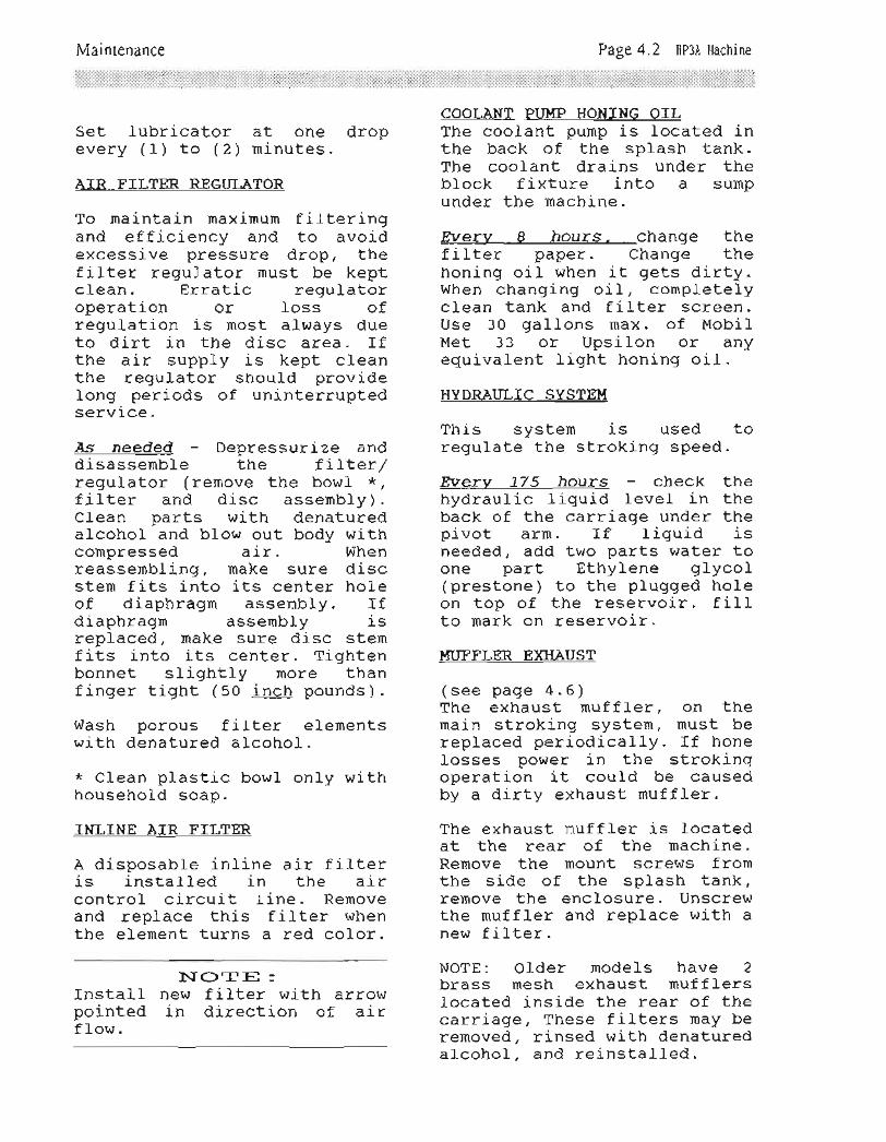
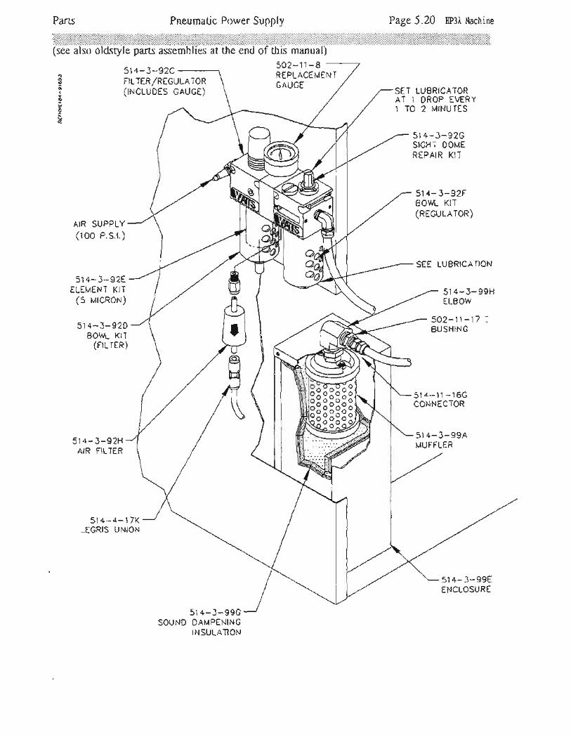
Set lubricator at one droPevery ( 1) to (2) mi-nutes.
AIR FILTER REGT]I,ATOR
To maintain maximum filteringand efficiency and to avoidexcessive pressure drop, thefilter regulator must be keptclean. Erratic regulatoroperation or loss ofregulation is most always dueto dirt in the disc area. Ifthe air supply is kept cleanthe regulator should providelong periods of uninterruPtedservice.
As needed Depressurize anddisassemble the frLter/regulator (remove the bowl *,f ilter and disc assernblY) .
CIean parts with denaturedalcohol and blow out body withcompressed air. Whenreassembling, make sure discstem fits into its center holeof diaphragm assembly. Ifdiaphragnt assembly l-sreplaced, make sure disc stemfits into its center. Tightenbonnet slightly more thanfinger tight (50 inch pounds).
Wash porous filter elementswith denatured alcohol.
* cl-ean plastic bowl only withhousehol-d soap.
INLINE AIR FILTER
A disposable inline air filteris instal-1ed in the ai-rcontrol circuit line. Removeand replace this filter whenthe element turns a red color.
bIOTE :Instatl- new filter with arrohtpointed in direction of airflow.
COOI,ANT PUT.IP HONING OILThe coolant purnp is located inthe back of the sPlash tank.The coolant drai-ns under theblock fixture into a sumpunder the machine.
Werv B hours, change thefilter paper. Change thehoning oil when it gets dirtY.When changing oi1, comPletelYclean tank and filter screen.Use 30 gallons max. of MobilMet 33 or UPsilon or anyequivalent liqht honing oil-.
HYDRAULIC SYSTEI{
This system is used toregulate the stroking sPeed.
Every 775 hours check thehydraulic liqui-d level in theback of the carriage under thepivot arm. If liquid isneeded, add two parts water toone part EthYlene glYco1(prestone) to the Plugged holeon top of the reservoir. fillto mark on reservoir.
HUFFLER EXHAUST
(see page 4.6)The exhaust muffler, on themain stroking sYstem, must bereplaced periodicallY. If honelosses pol^Ier i-n the strokingoperation it could be causedby a dirty exhaust muffler.
The exhaust muffler is locatedat the rear of the machine-Remove the mount screws fromthe side of the sPlash tank,remove the enclosure. Unscrewthe rnuffler and rePlace with anew f il-ter.
NOTE: Older models have 2brass mesh exhaust muf f l-erstocated inside the rear of thecarriage, These filters maY beremoved, rinsed with denaturedalcohol, and reinstalled.

Lubrication Illusffation
HYDRAULIC FLUIDRESERVOIR
LUBRICANTDRAIN SCRTW
Page 4.3 HP3A [achine
FILLER SCREWF|LL TO WTTHTN 1/4"OF TOP OF BOWL
GREASE FITTINGROCKER ARM PIVOT
(sorH stDES)
GREASE
GREASTFITrlNG
GREASE FITTINGOPTIONALCLAMP ARM
LUBRICANT LEVELCHECK & FILLERPLUG
RIGULATOR &LUBRICATOR
SET LUBRICATOR
AT ONE DROP
EVERY 1 TO 2MINUTES
BREATHERCAP
LUBRICATE DAILYSAE 30 OIL
HONE LUBRICATION
GREASEFITTING
GREASfFITTING
RCCKIR ARM GEAR BOX(cH[cK rN HORTzoNTAL POSTTToN)
GREAST FITTINGFLANGE BLOCKS(BoTH ENDS)
BLOCK HOLD DOWNFIXTURE

Maintenance Page 4.4 [P3A Machine
H:'DR.AIJI-I C
SYSTEX,i CHECK
With the machine running,watch the pivot arm and see ifthere is any jerking or bounc-ing when the Pivot arm ischanging directions, Slow downthe stroking sPeed to see.Jerking and bouncing indicateai-r in the hYdraulic sYstem.
b{OTE :At very slow stroking sPeeds,there *.y be some bouncing ofthe pivot arm at the bottom ofthe stroke. This is normal. Tocorrect this increase thestroking speed slightlY.
SYSTEXTT BLEEDING
The following Procedure as-sumes a drained hYdraulic sys-tem. Start at steP number 6 'if your hydraulic sYstem isalrebdy filled and has been inoperation.
l-. Turn of f air f l-ow from theregulator (1).
Remove plug from the toP ofthe reservoir (2). FilI thereservoir with fluid as de-scribed on Page 4.2. Re-place plug.
Open the valve ( 3 ) all tl.r"wiy. Be sure valve (4) isclosed.
S\TSTEI4
4. Turn the air regulator (1)all the way uP. The fluidIevel- in thb reservoir willbegin to droP. When thefluid is near the bottom ofthe reservoir (2') shut offthe air flow from theregulator (1).
5. Repeat stePs 1- and 2.
6. Turn the air regulator (1)all Lhe way uP again- Thereservoir (U should remainat least half fult, Tf itdrains betow half, rePeatsteps l- and 2.
7. Check the sYstem for anyIeaks.
B.
9.
Slip on a length of vacuumline to the bteed valves(5) and (5). Run the otherend of the lines into a canwith some water in it.
Open the top bleed valvef s I . Ftuid -and air willbleed into the can. Closethe bleed valve when theair bubbles stoP.
Ib4POR,TA}\TTDo not atlow fluid reservoirto drain comPletelY- When thelevel gets 1ow, refill follow-ing steps 1 and 2.
2.
3.
Irrc)TE :Valve (7) is Preset atfactory and should not bejusted. If adjustment isessary set tostrokes/minute with astroke at the hone head.
l-0. Open bottorn bleed valve(61. Fluid and air willbleed into the can. Closethe bleed valve when theair bubbles stoP.
thead-
nec-653ll

MaintenancePage 4.5 [P3A Hachine
l-1-. Set the lower stoP linitvalve (8) as far down asit will go.
L2. Push the litt1e Plasticbutton on the back of thesolenoid (9) - The Pistonrod (10) will go down'
1-3. RePeat stePs 9 and 10,tiffing reservoir (2\ whenneeded.
L4. DePress HumPhreY -va1ve(11), the Pistbn fgq will,io back uP: You wi 11 need; small screw driver ordrill bit to actuate theva1ve.
L5. RePeat stePs 9 and 1-0
again to be sure no al-rrernains in the sYstem'
16. with the reservoir (2)futl, shut off air flowfrom the regulator (1),Set the regulator PressurebY turning clockwise 3
turns.
1,7 . Do a sYstem check againsee it- anY air remainsthe sYstem-
tol-n

Maintenance Bleeding Illustration Page 4.6 IIP3A l,tachine
(11)
HUMPHRIY VALVE
(8)
RTSERVOIR
STOP LOWER
VALVE
(s)BLEED VALVE
(4)FLOW
CONTROL VALVE
))
SOLENOID VALVE
(7)NEEDLE VALVE
TO:
EXHAUST MUFFLERENCLOSURE

Maintenance Page 4.7 [P3A Hachine
vADJIJSTI4ENT
BEI-TR.EMO\ZAI-
CAUTION:Disconnect aII electrical and air pobrer before making any repai-rs
V-BELT ADJUSTIIIENT
Remove the cover on toP of therocker arm at the front-Loosen the conduit clarnP onthe left side at the back ofthe rocker arm. Loosen the 4
motor bracket mounting screwsfrom the top of the rockerarm. Push the motor back untilthere is apProximatelY 1/2inch deflection of the V-be1t-Measure deflection midwaYbetween the motor and the gearbox.
CAI-T:g I OITT :DO NOT OVER TIGHTEN BELT.
Tighten the motor mounting
plate. Tighten the conduitclamp. Replace the front coverand tighten its screws.
V-BELT REITOVAL
Remove the cover on toP of therocker arm at the front.Loosen the conduit clamP onthe left side at the back ofthe rocker arm. Loosen the 4
motor bracket mounting screwsfrom the top of the rockerarm. sfide the motor forward.Remove V-belt through the stoProd slot in the top of therocker arm.
Instatlation of the new beltis the reverse. See above forV-belt adjustment.

Maintenance Page 4.8 IIP3A Machine
Remove the six socket headcapscrews on top of upper gearhousing. Remove upper half ofgear housing.
Remove bearing retainer (51,4-6-26J t from the upper gearhousing. Press pinion andbearing out of the housing.Loosen the socket set screw inthe nut, on the pinion shaft.Remove the nut. Press thebearing off of the shaft.
Remove the f our screl/'tssecuring the lower gearhousing to the cage. Removethe cage and handwheel,carefulty. When reassemblingbe careful not to damage theoil seal. Note the o-ring onouter lip of cage. Ring qearcan be lifted out of cage.Remove the four socket headscrews in the handwheel hub.Remove handwheel- and ratchetgear.
Remove sun gear 514-6-35, fromthe gear housing assemblY.Press -out the I/8" sPring Pin.The adjusting shaft 514-6'43,and the thrust washers can beremoved by sliding down. Pressout the spring pin securingthe driven planet gears 5L4-6'32A. Rernove the gears.
Locate the locknut on top ofthe driven shaft 5L4-6-36.Bend the tabs of theIockwasher out of the btay -
Remove the locknut and washer.Press the driven gear 5L4-6-28off of the driven shaft.Remove the three screws in thebearing retainer 514-2-3C. Youmust atign the access holes inthe sun gear 514-6-29 in orderto get an allen wrench on thescrews, Press the shaft and
GEAR. BO><R,EMO\,ZAI-
CAI..I T I O}T :Disconnect al-l- electrical andair power to hone beforemaking any repairs.
Remove the hone head, dt drivetube nut. The drive tube nutis located near the adjustinghandwheel.
Remove the drive belt asdescribed on page 4.7.
Remove two I/4 socket headcapscrews in the front coverof the rocker arm.
Remove the four gear boxmounting screws, frorn insidethe rocker arm.
TOTE :Use care as the gear box wiIIdrop when all of the screlitsare out.
GEAR. BO><DI SASSED4BI-}'(refer to page 5.9)
Drain oil. Remove the oildrain screw located on theback of the gear box towardthe bottom.
Remove drive tube and driveyoke by holding pinion driveshaft, and unscrewing thedrive tube.
To disassemble universaljoint, remove its four I/4"button head capscrebts. Onreassembly of the universaljoint make sure all screhts aretiqht.

Maintenance Page 4.9 EP3A llachine
bearing out of the uPperhousing. Press the bearing.andthe sun gear off of the drivenshaft.To remove the Planet gearsfrom the ratchet gear, Pressthe shafts 700-6-5 out of theratchet gear.
Remove the feed ring 5L4-6-72by pulling it off ofhlndwheel. NOTE: Balls andsprings will fIY out whenremoving.
Remove ratchet feed assemblYfrom cage bY removing one t/4"socket head mounting capscrew.NOTE: O-ring, seal around hub.
Disassernble ratchet f eed as-sembly by removing kPob andpressing -out L/8" sPring -Pin.Ratchet pawl, sPring and o-ring can then be removed fromcarrier.Remove Auto Feed UP Housing(see page 5.13).. Remove thefour screws holding the autofeed housing to the ratchetgear cage. Disassemble autofeed unit. Unscrew the dragpin housing (514-7-33) ' removeLhe spring and the Pin- Removethe [wo screw and the cover(51,4-7-39J. Remove theihoutder screw (5L4'7-32) fromthe shifting sPool (5L4-7'26).Pivot the ratchet Pawl (514-7-29) out and remove the Pivotpii.r (514-7-3r). Remove theratchet Pawl. Pivot theretraction arm (51-4-7-30) backinline with the sPool. Liftthe retraction arm straightout through the slot in thehousing. Remove the threescre!'ts securing the slot inthe housing. Remove the threescrews securing the cYlinder(5L4'7'28) to the housing'
once the cYlinder is removedthe piston (5L4'7-27) ang theshifiing sPool (5L4-7-26) canbe puIled out from the end.
ReassemblY is the reverse. Thedrag pin assernblY should betig6te-nea until ?Pring isfuify compressed, then loosenapproximatelY L/4 . turn'nlissemble -the auto feedhousing onto the ratchet giearcage. rne upper geqr housingmuit be removed so the ratchetpawl can be seen while beingissembled, and the sPringloaded ratchet Pawl can beattached.
Adjust the engagement - of- thenarirl- to the ratchet wheel bYioosening the auto feedhousing hounting. screws, andmoving- the housing sidewaYs'Ratch6t pawl must just -missone ratc6et tooth then fullYengage the next-

Maintenance Page 4.10 IIP3A Hachine
FI-OAT A"rrd. CI-AryIPFLOATPress the air float button,located on the front cover ofthe carriage. The air f l-owsfrom the valve to the floatregulator, then to holes inboth sides of the float plate.This aIlows the carriagre tofloat on a cushion of air. Toadjust the air float system,adjust the air float regulator502-27-3,8 (see page s.3) untilhone unit floats freely overthe whole length of main base.
ITTOTE :Hone will not float correctlYunless carri-age clamp isadjusted properly.
CI,AIIPRelease the air float button.The air flows from the valveto the air clamP cYlinder.This cylinder tifts the clanPlever which pulls uP on keY int-slot. It may be necessaryto adjust the air clamP sYS-tem.
Remove the four screwssecuring the carriage coverplate. Remove the cover. Dis-Lonnect the air supplY. Insidethe carriage remove cotter Pinfrom slotted nut. Back the nutoff and then hand tighten.Loosen nut aPProximatelY I/4turn. Insert cotter Pin. Re-connect air supPIY. If the rodof the cylinder sticks in theup position, turn nut onenotcn looser or tighter untilrod operates free1Y.

MaintenanceUnner and Lower
Limit' Valves Adiustment Page 4.11 [P3A I'lachine
UPPER LIMIT VALVE
ADJUSTMENT PROCEDURE:
The stroking cylinder should be in
the pork position. Pull the rockerorrn down until you con see thetop limit volve. Set the goP tol/4" oelween the plunger bodYcnd volve nut os shown. Hone obore with no lood on the stones,ond stroke speed on high. lf therocker orm pounds excessivelY otthe top turnoround point, Adjustthe gop smoller. 3/32" is theminimurn ollowoble goP.
1/+" MAX. GAP3/32" [/tN. GAP
ADJUST BYRELEASINC NUTAND TURNINGPLUNGER BODY
NUT
PLUNGERBODYPLUNGER
ADJUST BYRELTASING NUTAND TURNINGPLUNGER BODY
NOTE:MAKE ALLWTH HONE
ADJUSTMENTSTURNED OFF.
ACTUATORVALVE NUT
PLUNGER
PLUNGERBODY
NUT
BUMPER
1 /32
LOWER LIMIT VALVEADJUSTMENT PROCEDURI:First slow the stroking toits slowest speed. Thenodjust plunger so thotthere is o 1/32 goPbetween the bumPer ondstop when cYlinder reverses.
N6ooo
I
UzrE
LIMIT VALVTS ADJUSJMENTHUMPHREY VALVE
VALVE


Front/Right Side View Page 5.1 m:e Machine
zi)- -
-2 aoJ- V--cI o>;= FtrOi:{o-lo=-!- FLtl fl/)=rE:: (J=o_
nA67N -r0
I HFuHES c'3.''<*" za?qZv0agF2OO-
=6*3?n oY) u)
Lr.llzlolrloll.r-)
|
o_lrl
rX<F6sFoo-Foa
:<s(J^;-.r9ai, coo-3-rEbJQ*:3o.f(J<
J
zotro-O
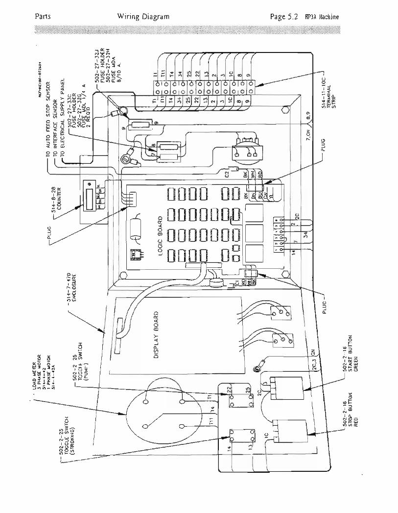
Page 5.2 HP3A MachineWiring DiagramParts
N9!Nf:?<5?59"I trJ I LJoN(nNflrolol\lr)LnLr-@
a0FoI
9- ilu=2V-Fl,3dzrEil
Ap>,
^ 6dH(,o-LnAa
EU5r.-SE- (r ,.
=HH<4Lt)
OoFlt<-2t>L+Ega
FIJF()F(,
c-r!( o\l')l! N-!3 ?_-.rlo lo^
T: i:"frC.-l(, N(,ftot o-tr)L rrLol
COvNilIF@zr=+v
lr)
ouNoa
lctr.. oIJ+O()uJ
85gE *!*9uiui<d+^ +:iml?)-()
nnn
ilililililil
*#pilil3#il'il#
AllaFL10ts@
OE.
oco
ILU).
zotr
G)-;d(.lFzI oa t.lN<UJOFGf)ur..9
o.F.: :]lcoNlo_Nc)O
OFUJoat
-OFR;J.:cl(Jsc.r(J-ooi-roFi=
ICJF
R-9,t&u.1 x.ltsEI Pi3

O
gl'l
5l-
n
gE.
rF7Aq4.U-o->
v.OL!FF
(nFNrL!Foou><blI:rao-rooNn(o
vLrl
=o-
z=-o8i 9
o-Tts€EzIUe
Wiring Diagram Page 5.3 HP3A l'{achine
LllO+oo-tdf+!El.c)(,3
tL!Futv.x><<l
l,)Ft,l(,o)FO'Ot O-zciriD6>JE
o
f;frR;lOqro-t)tz
n- 9.= FN-(rl*I u I t-r.tN(,r)N(no:)of
LOtL1r)L
ael
*13o-l (/)l
cix&nH'-t otYlr=#x \N-N €It-.tlu-N(,Ntn1
----u(.)L!-)LL>
E?- )m. Oll LL ta-jl- (ou-or!
T=H f;EN*eFfi;q53
(n,t!
<R
=66-F--.1F<<<sz-er!_Ez-_Lt-OFc)<-:E-_ru
) ,ir.tu-.1o ,
'-l <.2<el oXa-l o<Eq?trI F=J
EI ES2-l t-..i<<
o_
=lLiJ O-O-Flzr/)<r ---l
S8lr)O
-t!+(Jl<eTp3VLa
-'- LiJLnzA
LiJO()NozlovNzAI l,-.1oa
<-JL
r",9s
IO(trrFq=
I u,l
T*ezlr)J
otItoE. rp
NTbon>
i<:<2.Fo(J>trJ 0<z.b)zv)R-VXof,
L!.lmztoleFllrlrl3<lo(Jlo-
EEO

Parts Schematic Diagram Page 5.4 HP3A Hachine
Uo<e,LOe. ttu2FUza
oz=>oo- <to)FFUootr
(!- t-()I O>l =
N(tvt:XYotlo
z.otrFoE
85FUOE,
rE tr'fa\arl-l^tFei.l
n6 -l'
oFlFF-a)lto .l
ERI
:l:gF t-l
^l*"1
-l*lNIeltI
x+
iFFrJdaS.\
tr)o
6
2uFrK$9---d
K14
oN
c.l
F
u.o

(see also oldstyle parts assemblies at the end of this manual)
Pafis
51 +-7-77CLIPPARDVALVE (TLOATCLAMP)
TUBING
AIR LIQUID
3/8--->- -+-I /+ --+- --->--
1/8 ---+-
Pneumatic Circuit Diagram Page 5.5 IIP3A l{achine
oo
I
Bd2aBrE
SPEED VALVE
RAM (POWERSTROKTNG)
514-2-65AHUMPHREY VALVE 51 4- 3-30A(roweR uvrr) BLEED
FIXIURE
51 4-4-1MANIFOLD(srRoKrNG,FLOAT &CLAMP)
514-7-59VALVE DWELL
51 +-2-61 EMAX. STROKING
5'14-2-654HUMPHREY VALVE(UPPER LtMrT)
rrlL Ifbi] I_J-_ tr
514-2-62VALVE (NEEDLE& CHECK, HYD.MAKE UP &BLEED)
JEI -p- - --r
51 4-2-61 G
VALVE(STROKtNG SPEED
coNTROL)
514-2-63RESERVOIR
514-3-264MANIFOLD(srnoxtr.tcSPEEDcONTROL)
514-7-40ESOLENOIDVALVE (FEEDour)
514-7-45CYLINDERINTERFACESENSOR
51 4-7-58CHECKVALVE
51+-2-70ESOLENOIDVALVE(sroPsrRoKrNG)
51 4-2-68ASTROKINGVALVE
51 4-3-99AMUFFLER
514- 4-33MANIFOLD(ArR SUPPLY)
51+-3-92HAIR FILTER
51 4-3- 93LUBRICATOR
CONTROL--\ \\ J6JI\\_Ld--t El
I
{
tttlEX.
502-2-11CLAMPCYLINDER FLOAT
502-1 1 -35AvALVr (rlowcoNrRoL)
502-1 1 -35AVALVE (FLOWCoNTROL FLOAT)
502-27-17RECULATOR(RESERVOTR1s PSr)
AIR SUPPLY
100 PSI
542-27-17RTGULATORFLOAT
HONE PNEUMATIC CIRCUITIIITH SHORT STROKING &CLIPPARD (FLOAT/CIAMP)
51 +-3-92CFILIER/REGU LATOR(tNCLUDES GUAGE)
AI
-<+I

Parts Electrical Power Supply Panel
HONE MOTORSTARTER
Page 5.6 [P3A Machine
ELECTRICAL230 VOLTS J PHASE60 HIRTZIMPORTANTELECTRICALLY CONNECTIN ACCORDANCE WTHNATIONAL ELECTRICALCODE AND YOUR LOCALCODES
NoNNooIo
Uz
€
L-PANEL MOUNT STYLE
502-27-32JFUSE BLOCK502-27-32HFUSEMDA 8/10 AMP
502-1 1 - 3X
502-27 -33AFUSE HOLDER502-27 -328FUSEFNM 8/10 AMP
MOTOR STARTERENCLOSURE
700- +STRAIN RELIEF
+oo-l-8CORD
Ll L2 LJ
FOR ''H,' TYPEHEATER ELEMENTSSEE BACK OFI'/OTOR STARTERENCLOSURE COVER
TO CARRIAGE
502-6-8CONNECTORRIGHT ANGLE3/4" (2 REQ'D)
CAUTIONDISCONNECT ALLPOWER SOURCTSBEFORE SERVICING
502-11-11AcoNDUrT 3/4"
(2 RE0'D)ELECTRICAL POWER
SUPPLY PANEL

Control PanelPats Page 5.7 Hp3A Machine
Ll-j- r*tdIr- a.]l;l
\j' \J
-7lr)r!
0_
Ec-: l:ovl
Tiizt>NoaC]uJ|r)F
r t V rs 0-nU^r 2,.CUr=r-Y'- {N*Ni u.t I t.t
NL4N(./)Jo:lolotJ.)L-tr)LL>
l'l) o)c! c!J u+ -,.1, rr /^ \J , (J
I VL IJL
33=Jfl=LoF(rAAA
od?
I@^I ztr [9 )lr.rbt viAUu,J,dl^l
r'. Y r'. {c{*NI ur I rr..iN00Nmo
rololziItDLTu)LLLLI.__F+
I
L!JFnoJo
o(oOo1- 2- Lr-Jl4e
+J-LulnID E.J
()ir-,tll
t>NOo&lf)()
r<i,r !
Itro@zEItJF+FZ
lr)o_(J
(Jf^)(5)o-
>-l aal 26l .-LrJ<l :-
,l til ^
4a se<l -t ooa-lt- Z LrJql | -v,l*-dJl FA<'OI |'.)Y€rlFl a-l
tJj
^l oYl o\Jl v
+()I
f-. ,. orU0a+o<-arOn:co
@*rI LrJ
f'- )<rO+<.-ftlr)cD
<oLId@Ooc0
6NffI !,1oFtZ.:3
Lo C)
|r)rf)
It-I{-
6
v.'M >-
T ?.-,rcrEI zLtJi==3
^on<<P
()
^JQ90-uRtfo
. AL!)Lrll O :lMl )ftrl o<nl fi>Yl rr ,., (,ql95Eal^lJlLlJl vl L
lEl > --.:
di Pl8 "-all Ltrl { c-r-71 -^ Lt)o-i ==Ol Lr^0.5^aUJFO
sI
@rO+o-ztr)\<
i-rJF
Jo_
tlr,i t-lOOLLJr!oOEFF
=2.roa<)
)'t!(oF$<li
-r O-1 LrJ
+2az
co
ico
I+u-)
(ozot-
XL^ NFOzYi= I o.Ftr'adE 3e5UI')(/)coo
(o
I
NI
Noro
N
I
+I+
ll.
x.oF
r!aIo-
N+I
$I+
n
x.oFo
LrlV)
Io-f,-)
E.trJFL!
oo)
-F<-.i-rrrN1'.; 6-;FFFr/)NN'_cqrOEOOr
;_^>f\^ Y/\\i-.:.---1/

Page 5.8 IIp3A l,{achineCarriageParts
odd6_9:j ooa4 N<E tve OtrttY
:80a UJJNN-.o\)7
N_
T3+cotx\+ UJFJ(,)L
0\+.6t','()+<tEirrnOo ? r,-i| -Jr.!+l:roJj=i!
o>;z
)oEAFc{z
r(Ji=9+o--JrJ{U)tL> O
r.)-Flzr+<r -JLds88tr)OI
L!lc)l<lMIMl<lOI
$aI* 0i u_tt-L,J>
=6ilr)()>
FL!)< 0<OO<F(Om>
E.?9\5 r-)LiJ , Ljlz.- Jz*c)ovz()oa<
@I
CO
I
NOu)
+t)F5oz.oO
I
I
Nolr)
l-r-FlENOrO-+Le
-l<Loa@
E.LJJ
oCJ
Y
gl
F+fo
I+I+
6
Foo-
Ft!
I6
u-)
I
NI+
tr)
rO
ILJ- O:(I z.a+<o-JJLf)t!nO
Er!FzfOo Lu6o9bz i,HtrJ40{n(n rn-:.
(o
I
I+u?
E.
CD
FEoo-o-fa
ccl(O
I
I+|l)
O|-.
I
l-.I{
n
+llJJNG>l_ui<
=F -> Ld:or.D<)A
=Lrl6(oEl9o-=NI-ro-O(J-lr)>-r.)
ia(E+o,-r_5=-lJl(,I Z4-.NZP€ooF\ir)/'J(nm
r-)NlFNfI o:
NZ@OO\'o(Jt)
ooI LrJ:
->C\lr{\* t.l .:-'-I Ito c.o F-)
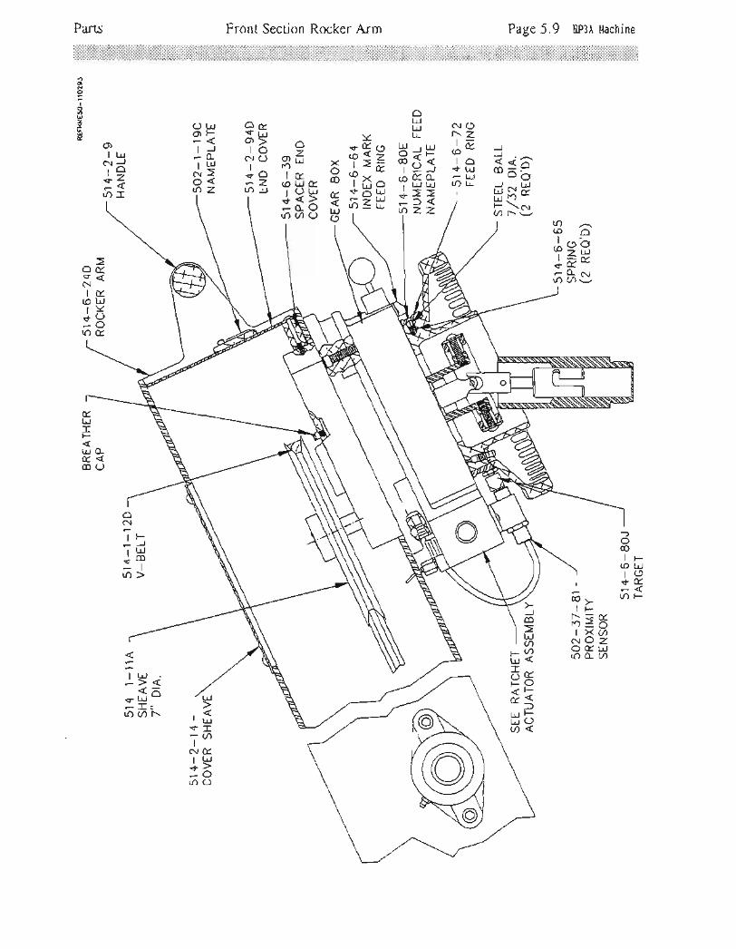
Front Section Rocker Arm Page 5.9 [P3A l,tachine
oN
IooUzEu
_l< <A0 =.-LJ Or
d-PLrJ -l') *Elg
N('l-. ZJEIO+l!
F Lrl[O tL
Al!L-LJ
LLLiJ , lrjo=r-P6{
I -J,oeo-i r.! L!
-l->>l:<tOZ-Z
Yst9r5=
TxI+;<LJLD4l!
ogr ><
Jr- 3
i35 -xrOcrO 6
OL! OrroF +ilr{ O>rf to-LL NO
I LLIIN4 .+Oo< -zAZ tr)LJ
O)I Lit
C\JrO:=lr):f
lr)(oO
4:gJas6$s9
o0(+<Nls(oL!rY:8n&
-)o00IF
(O trJl()+tr
lr)F
ac\l
IF--J, tiljco-ttr)>
Trl*r=fff.)zOI xoerOzo&uao-a
JmLrJaa
t-oFlF(J
Ft!rOF
tL!LrJa
I Lrl
r<^+ rrJ
-Irro Cr) l'.L!
t!-u')
E.UJ
oO
+I
C\I+
Lr)

mis manual)
Drive Pinion Assembly Page 5.10 Hp3A t{achine
z<oN;N4lrL(o., IJJt>\f,-
._oa()o
Parts
(see also
.\s\\
7l
,r/t"'((
\ '-- -.
\\
\r-.L/v
-->>.r''t€''<'\.\ .r
\,/
\. \.
\\
NoNNooIo
UzIE
E.L,\sl Flttgl o2l z
LIll -<al'rnl LT
?l sEzl%'-Ol O c.t
-l EN'l (o
nlr-*l Fr-,-rl = 9>t-t
_ltl-l E'Ld
a
zLdFI
=(JuJEmo K' r---
(J^ \
-LnAZI ?^r--z:,6lO#or+J-.-)-clOlr) ZJF
JLrZJO<42FEo-(r<< 0- LL,O
L:1M,. F = I
=3*uE-TSocbEN-J
, q Z -
--lJXad*-=n/T^o>o6tr
lLt
t<+t!-Iaa
L!()ol-z)
=tny<4.-F
g5F-cJr->:F.- |ri+3qO
io
*=rr Lrl
-L
=O-(,fOuI i,r6(n
parts assemblies at the end o

(see also oldstyle parts assemblies at the end of this manual)
Page 5.11 Hp3A Machine
+r.O_Jl<(oLJta
+_J65
Gear Box Section
FFI Lr.l(oIlS)i?
o&.
Parts
Lr)oal.)<I tr-l
(o(9I+Z
-lau))€
aFE
7- o-.Jm --.'|
2<<LJ -OAtn+(n;i^l<6re9-?"l>-r
lf) o95
(,zv.
co\F
[.*+l <r-gI. LO
glt r. <Ql$es--l tfir5l? '., eHl+<+Ol tr)OLo
+
tLdIlu)
D=6lF--(oCDYr>#+G-
lr)F,l-
zUJ
toFLL
Ia
(Orr)
I(oI+
lr)
LrJ
4Y(o^(oLJro(
oo-o-tor
N(oI
@I
<.LO
E.trlzaFLrJx.
(JE.co
)L!L!I
=ozI
(oc!
I(oI+
|r)
xl^l(Jtml
MI<lLrlOI
ef;INl(J I9z ,6
=T +Uu10 fi8
sIa
(') oo @ \ il{^r.alr) + I I r-tr ?EJe ,if 32 32 R;i7 '.lbiz- tt t;) l= l)& tJ
;fr ;5 F3 HJ FE!;#
oI
U2trutF\Jro{tA
,Ofrl>-zn:f
J
=o_
Ir)rC0
-oozlr)Y
,; z-
f;Ea K=,l ug 4:+?* +t6;5' 6u
-)o(o
<s<l- \rotr)
I(oF-rI+<-Ina
C](9> OE() OO<('-.2) -<Z c{<Z,)61tr |.l!,lA N^r!;i
tdf; rJd qJd;;? ;=- ;il'
il)fO
CJuCD
_.1Jm
It-Ioo
tr)
r-Ae'a
ff3u?L-l-v(o-+:t-E ul()a(J
EUJ
=?a\j- <t=t)IY.+O-o(]J
LJLiJ mco :)F\
-d9--o= -:tsb$qlLLi lut(oJ(oJlt+<+<
6 o'6 c;
..trlFI(JlzlL!l--rl
)<lOILII
=lOI
co
f.)I
rO
IFCJzLJ)<O
It!l>lLllurlilA+eIr!(c)JtO-<-l
tr)()-\l-
f')sl-
,(oFILL+<
-Ia(nx
F.<- t!.+.a(O!
\Etr)<Fr LrJtz=1o_
Fz
J
aE.L!
z:f
LdY9\tul>@Eio+
6*r
@+I
@l+
lr)
|.)La)
I
(oI+
LO
Fz6TE)ol!QEE*mJ-
Os<f3lz.
f.)I)<
+C.)-o|r)J
v"tlJrIr)N<r-)=
I
@FN(nll
OEOI-F
0aLJz
o<rDFr Lrl&E
I
<-v-oalr)Gl
r.)r-)Jt<l/)t!1a*:|rJo
Fz.:<Oo-l
Ioolr)
LrJ
Eozozo-
|-..N
I
(O
I+Lf)

Parts Carriage Float/Clamp Page 5.I2 I{P3A Machine
see also oldstyle parts assemblies at the end of tfrii manual)
Xt!
oN6o
I
n
=LUE
IIEa
-4n FE<-
T=f; i?:sH!; 3 53s
o_
$u+<tE
IElf)c)
UJL
3kTdI"D Flz+O-trl')l!
EttJ
u: iaI A--
orS{tvUd_0.Rf;s
=UJu.8eo(:Lrl-OQ rb
t!5t"o<* )sl
E.
15b ^-r
&sI+>
- LiJrO:.
@^
fsgI )NNJ*OO^,|r) tr:-:
zoPI-. Fol)lco
t/)r=+Ln-:lrn o-
LrJ
't o-
NJF. O -C)r E\Ti?$q9,:o 5t>
LIIOI<lxlVI:) <lzOl
(D(o
T ?-onorEI ul0<+>F!s
t
Fo-LL>
=JQ<)
lr)I
F.)I+
6
vCD
L
J(.)
roI
r-)I+
()
E.t!t--
(JL@
I r--(t- (D LtJlrfN&vl3E:
E.
t!E.
LrJF)o-
EtrJ
oU
coo,N
Irr)
I+lr)
U?dI
n0aILl:3|r)O

Parts Stroking Control - Air Page 5.13 HP3A Machine
zoF(oF
r, =)lrD
T=c! (noftr) o_
<=lr)onJ^
l-urFil>FNJZo<olr)>o
F-rrT(,. oI >FFF\=UJde.rF-)<jl1()aerl<6o(J(fLr|r)>(Dg
)
-., 8?z+<f,85g2.Ede*9.d d
t!-.)
vLr,lfC)
F@f<(rILJxJtiJ tP3
.o9+E-J31rn>O-
=oJtLv;iL.r EF>,=xs8;
F
rnt-)
I
I
c.tolr)
FgTOIF
l-. <C.liulf <c!(J-
olrlirn Oa U-
I\r-
Itr,
NI+I+
l.cj
ozzE )<^zH9>t":<tr--l> o-:i>
JoF
otOlr)()I
nu:jI >r.d+ --.1 =
-{arn >5
noNPi^N-n=!vA(DLbgE @ft;to*r'rl-
I Ur^+<5'fi <9
<lj<lFlt!tol
llolEl--l)
8lh-llogldol
(9
6I
c! t!t>+Jlr)>
l>L!+!=rr, >3
)aloat-z(DO
ro(J
zoFF:fcnfi'-i64d3
r\o)
I
r?)I+
|J.
d8rSHF==-<JZL-^ uJu LlogH:<tY@E8EEan4 U1<
LrJ
J
u.t )a?o5lovl-.2 ^
s=urn (,U
(,z Lt)..:<>U^i
FFS.\-o
iiH()>(,
dEu
:>gEiB
rD
1t'5+liHo-l')>O>
JoE.FzO
(o_(9c!qz.LOr<O"., l! O trJ
J=HHtr) >ii
LL,oF-ar6N?r,rrG5sdi{>a>
mu.(o -ir>c{EI u.J+(,
-L!rOft
@rO
I
F^.I
()l^rr ll95l:l€
gl #l-Pzl c,lasl;lE.rl>iazl=lt:<l <lF-l=lo&l=l'FlulEatzl=
LL_l
rcorT o.^h 1t;, =u .
.lu d ll o-O tr.l r* ut() 0a3-
F\NFI LtJ
rO+<Ir) CD
(J<z}E
l-
:- co
surr) O-
JUJ
L!)JJL-
@(,(ozetufiI >F+JE
,6 Slt
L!F<uJ=zIrJ^6luE +O<l-:Fo-u(,. trlc.r E oi_igEL
=-d:O9)Z)L!<(J
)FLrJotrJL!

Interface Sensor Assembly Page 5.1.4 [p3A l,tachine
LrJJ
- 's 0( LrJr---OEl-Vnr*nLrJY
*so Z *tr> - oi)
O(r Ld
=9Eoo2#0.;-l:o<u Yt,<p3
lr)+
I
l-.I+
(')
o
IooqzIE
()+ErbtNO12.+J
lr)O
r-l nfiOo.41-(,i;<L!s?isi
(o
I+I.+
tr)
F:lz
o.-dLrl (O rO.-*dJ_9
l-iorUJI.)
?=i>-i+
F)z.?
E,t!oz.:lO
tJ-lr)y{--la
l-- C)lr+c)-ztr) I-!
E.
Unz*ilJY:o-o(or]trO
[5.6\o<cD!l-<U- =,2r,-fiPo q.x.oo-z u>-trJ u _l
FJOLL:lF<LL
E-
az-Ld(n
oELL
UJOzFa
oLdaatrJE,o_^
S2F, Lul
J-i,J-9* ?5e6 >32
-Lrl \$c) \I <M \N+6t \t(n*-uz-'-Ldtnza
LdlJo
aLrJcf.J
\tI+rFF- LIJtz
JYlr)>
)<OJco
Nnl lJJ
N LLJ t!rCDE+coo'-10<tr)ft(9
ot"!a
LJF
==

Ratchet Actuator Assembly Page 5.15 Hp3A MachineParts
€NEI L'J
r.- O'| z.j- J()O
a\J,
\-./\v\
tr)lcrNZt. a.\-l
lf)O
o
I6@
2rt
lt-t/)lcr
It- ZJ- a.:ttr)O
z()Otr) Frc)l-- <lo.:+F2-Ldffl.r)0a<
lr}1gr\=tA:3tr)I
(orr)Itr
5 L:J1O-+>
-lIf)Cn o@FlLd(c))<rO:#()co
Jooo-
@aTo{z'| F
LLLs--:Eaa
<\lr)\T.r\.'--Z \'r E \+<- LrJLOm
=z1[l-'. LIA+>6o-
zoFtno-
l-.N
I
l-.I
:f
|r)
Nf.)lcr
l-.' z
j-itr)o
'r)rr)tE
NLd,o_-L>lr)co
l-rf.)lc>
l-. 7t.t'l|r)o
+tt) zItr
t-.rc)s{-oilr)0
+f.)
J.', z+0.-a_L{) U)
O)N
I
t-.-rl+=;<lr)o_
@rr)I rr
l-- Zt-:.8
lf)O
(JzELdc0
cnr{)N
I
|-..I+
tr)
t0-Yt Aa
:EOnoI
iltrlo
NJ={=tJ*os-IOr()u)a

Parts
51 +-4-89ACAP (UPPER
cv[tuoen)51+-7-378
O_RING (UPPERcYLTNDER' sEnl)
Page 5.16 Hp3A uachine
51 4-3-1 0FSCALE BAR
51 4-4-tOANUT
Stroking Cylinder
(see also oldstyle parts assembtiei ai *e end of this mi;nail '
51 4-3-1OCBLOCK51 4-4-9OB
ROD & UPPIRPISTON ASSEMBLY 51 4-3- 1 0D
SPRING
514-2-60DUST SEAL
51+-2-52O_RING
(RoD SEAL UPPER)
514-7-37 AO-RING
(c,ee srnl)
5'i4-3-30ABLEED FIXTURT
2 REA'D
51 4-3- 1 0BSTOP (LOWERLrMrT) '
51 +-2-39ADJUSTABLEHANDLE
- MF-1 631/4-2o HEx NUT
MF_ 641 /4-2o x s/4LONC SET SCREW
51 4-2-654VALVE (LOWER' LrMtr)
51 +-2-52O_RING ROD,PISTON SIAL
51 +-2- 50O_RING
(PISTON SIAL' UPPER)
514-1-178SPRTNG (STOPROD)
51 4- 8-9O_RING(CYLTNDER sEAL)
51 4-4-864INSERT CYLINDER
514- +-77O-RING BUMPER
514-8-4PISTON LOWER
514-8-2AUPPER CYLINDER
51 4-2-52O_RING (RODTNSERT stnl)
51 4-8-1LOWER CYLINDER
51 4-8-3fND CAP LOWER
STROKING CYLINDER51 4-E-9AO_RING(CYLTNDER SEAL)
51 4-8-1 0O-RING(PrsroN SEAL LowER)
HUMPHREY VALVE ASSEMBLY 514_3_14E

Lower Travel Limit Stop Lever
100-t9THRUSTWASHER
CLAMP LEVERREALIGNMENT
Use otubin gfitting.
nylonwith
sToP (LoWERLIMrT)
51 4-4-5A
514-3-12ASTOP ROD
sTuD (crAMPHANDLT)
COLLIT
TUBING FIRST: PUSH
cAP (UPPIRcYLtNDER)
51 4-3-30ABLEEDFIXTURE
UPPERCYLINDER
51 4- 2-30BRACKET(cYLtNDERsuPPoRT)
nUROTATE
LOWfR TRAVEL LIMITSTOP LEVER
VIEW B_B
51 4-8-JCAP & PIVOT(LowER CYL|NDER)
LEGRIS TUBE FITTINGSTo Disconnect Tubing from Legrisfitting-push collet with o screwdriverthen pull tubing.To connect tubing to Legrisfi!t119s just push tubing into fitting.NOTE: Tubing must be oll thewcy in to seol tubing. First post ogripping ridge then thru cn O-ring.
514-3-25APrN (PtVOTcYLtNDER)
100-19THRUSTWASHTR
51 4-8-1CYLINDER(lowrn)
Page 5.17 IIp3A Machine
SICTION A_A

Parts Upper Limit Valve Page 5.18 [p3A Machine::::::;::;:::::.::::::;::::::::;::::;;::::;.:-:.:.:.;.;.:.:.:.:.:.:.:.:.. : :. :.: .
: .
:. : . :. : -: .:. ;.: . :
. :. : .: :
: : ::: ::: :: :
::: : ;: :
: :.:
: : :: :
: :
:: :. :. :.
at the end of'*riS
ooo
I
U1uE
51 +-4-64PIVOT
SUPPORT
51 4_3_99cSOUND DAMPENING
INSULATION
51 4- 4-66SIDE COVER
(ueeeR trurrVALVE)
51 4-2-65AVALVE
(UPPER
LrMrr)
514-+-6ENCLOSURE
(LtMrr vALVE)
51 4- 4-70ANUT
ACTUATOR(vALVE)
51 4- 4-69CPLUNGER
1 /2-?OUNFJAM NUT
sl 4- 4-688PLUNGER
BODY
51 4-4-68ASPRING
514-4-A4SNAP RING ,/z'
s1 4- 4- go] -'ROD & UPPIR
51+-4-648PIVOT
SUPPORT
51 4*2-39CADJUSTABLEHANDLE
I
'100-19
THRUST
51 +-2-+38SPACERADJUSTABLEHANDLE
51 4-2-398EXTENDERADJUSTABLEHANDLE
JAM NUT D+T51 +-J- 1 2ASTOP ROD
PISTON ASS'Y .." --'/ t/51+-3-7D--/' ,.PIN-(UPPER .,/ ,,PlvoT) ,/ ,
51a-a-sa-./rtvvt) //
,/ / li \l --\
5rn-o-ga-'/.,,/9lfi\sNAP RING ,/ , I A \\ \
s14-+-6BA-/ / L'o-o-un8 L11,2-31yrur/ _r r+_z+_ovu JAM NUTSPRING / PLUNGER
5i+-+-6BB/ UPPqL-Ll[4lr:YAlvt &PLUNGER ,Uf,f,IR PIVOI
BoDy *'"'']53F1)*?r".!ilj?t$o.*
51 4-4-63CBUMPER
51+-4-62ACAP
514-4-6'lEUPPER PIVOTASS,Y
514-4-618SPACER
51 4-4-63DBUMPER
D <.J

d@@oE
I@
z-Uv
upper prvot LockIVlotor - Safery Switch Page 5.19 Ep3A ltachine
LOOSIN CLAMP HANDLE.UNSCREW IHE 2 DOG POINT SET SCREWS IN THE SPACER HUB.TURN SPACER UNTIL SIOP LUG IS 45' FROM VERTICAL,TIGHIEN CTAMP HANDLE, WTHOUT MOVING SPACER FROM THIS POSITION,UNTIL UPPER PIVOT IS LOCKED TO PISTON ROD.PULL HANDLE HUB OUT AND ROTATE HANDLE UNTIL IT IS JO' UP FROMHORIZONTAL AND THE TWO HOLES IN THE HANDLE HUE ENE r-rrViO UPWTH THE HOLIS IN SPACER HUB.
6. RETIGHTEN THE 2 DOG POINT SET SCREWS IN HUB OF THE SPACER.
1.
z,J.+.
5.
UPPTR PIVOT ASSEMBLY LOCK
ROCKER ARM
51 4-2-41cAM (LlMtrswrcH)
CARRIAGESET SO BOTTOMOF HONE HEAD IS5" LOWER THANFLOAT TABLE WHENMOTOR CUTS OFF.
-/,J'LOWER
MOJQ._R.CUT OUT SAFETYSWTCH ADJUSTMENT
51 4-1 -56LIMIT SWTCH
Parts
(see
Pneumatic Power Supply
t:i::i:;iii;i;iili:i:riiirii;'ii:iti:::lril;ir::iii:iii.;i:;ti,.::::.;ii::::ii:l'::::j':ii::i::::i:
REPLACTMENTGAUGE
Page 5.20 Hp3A r{achine
SET LUBRICATORAT 1 DROP EVERY1 TO 2 MINUTES
51 4-3-92cSIGHT DOMEREPAIR KIT
514-3-92FBOWL KIT(RrcuLAroR)
SEE LUBR|CATION
51 4-3-99HTLBOW
502-11-17 IBUSHING
514-11 -16cCONNECTOR
51 4-3-99At'/UFFLER
q1 A- 1-OOtrENCLOSURf
oldstyle parts asiembiiei ai tfre'enA'of ttris'*i;uajl51 4-3-92C 502-11-8
oIo
I
oz
FiLTER/REGULATOR(TNcLUDES GAUGE)
AIR SUPPLY(ioo P.s.i.)
514-3-92EELEMENT KIT(s vrcnon)
51 4-3-92DBOWL KIT
(FtLrER)
514-3-92HAIR FILTER
51+-4-17KLEGRIS UNION
51 4-3-99cSOUND DAMPENING
INSULATION

Splash Tank Coolant System Page 5.27 Hp3A ilachine
ii:;iil:';'::jlii:it:iiiiiit;:ii:iii:ii:i::::::iiii:;i:iiiiiilii:ri:ii:::iii;;:ii;i:::;;:::i;::::::;j::::;;::::;:i:::::::i:::;i;:ii:ir.ffi
Parts
z:6
o- 3oo- =
a ;-BFH b= tsd'=f=q.'': 7 -r
FJ -FiO_"
i-t ? r! tO tz9*,^ -\FjHg iE iH * ss* ;g;s
+:\rf,
^, r r.r- {\:o, =r)
=sA l=I z? r 6368 s6()on lr)()
v.
Nl z FU,ri i- E nzI o<q r'El- O.^ f.-. Cnr[: r:3= r*aav) tr)()
6@
It') 6.1lJ+o
r{(]F
{?n -T?€tloI l)-+o*--JFlf) L'J (.r)
=LrJftOao_
n{NU^
ig3'' ii ulI XMN(J*8{3
c\T FI-o
T zYra.r>LQ<+() --fv
. <Ld9^;(JryF<I (JoaF\ LI tdI ZtrO:95dIr)mml
>l)<l lJl
1Elrl -lal-lqel:l rlht gl
OI
o
IrUzUE
h.,F^1=
r-a;'SgI|.)=<:39'f)>())<z
Lrl 3@
tNI
ntilcno2r-O-Oi1
<-<Yo-ro co o Y-}
o_
tq̂=E trJLrJ
'>f,89
(J1..)(o
IN
II
'hLtJn@Fl4zTHH,*+tr0(F-fOJAnntt
o_
fa*b)U:3EO>
mt.)@
I
NI+
6
YzrFo-efrU<-)+o-(-J rnFv
tLo@
I
f-)I
lr)u.UJ&o-
trL!FJr
(O(o
IF.'
I+lr)
E.LdLtn Z|.)?=@oo
l-NtrIUJO
+FJ-JOtf)frI
--{M-J,U^ILU
Ni>oo<Lo x. z,
wYaz5so--I9?--rtss
o@
I
t)I+
tf)
:<z.FIaJo-U)
z@(o
Ilr)
I+lr)

Block Hold Down Fixture Assemblv Page 5.22 itP3A MachineParts
Y<90:^wY<--t-#m {l* zFJ& O
Ji=F->Jarn(noJ
.tt
ot-rl.^l=-*e
-0_tn (n
(ozlf)Fdlv.|.)O><rO-L!+o-o-)zaa3
NaoooIsr4UJ
=aE azc ()<lr?xlLr$6az
o)roulu{|.oJroi:a>lr):tro_
Eco
0_
J
$I
f-tI+
|r),t,
FE.oo_o_
r.r) ;; nT(/)FT5F+o-6dSy
D.
T1It- Ot-:Tdtr)i<
p
N +ZF - nO'U,j't 'o J-,9 g.1 LrJ t i,ai-ft * tr or
nisr F il fr
LO>lJ
f-. OI
i;E|f)(t<
<>l0-IxlLrtOV> z-
tJ.lF
COJlo-
t\',><I t-t
'foLl) z
.olTrl--IZ+a6>
zl >t
ildl-l Lll
2lElol <lTl II L-II:<l o<l
qilml Lr-l
-a*29-oI | .-Nt!
='t Z.A
:<oU)> t:
FItl Izl(,I<l-9J1aa<oII
Oo(oI
l-.I
$tJ')
'ag?I rr-r
It- Ilo<f,<
-ELr) Ct
U)
Oia
Ozf
mE()'coglz
t- --;IF
$F-LdrOA
ooL!E.
N
YLJo
.ofrI u-.tr- (Jlz.<-<
rJt()tL
-oolJJt(\T
=UJ<u.o)OeU1Ir'. O-l>+<
-Jlf)O OIt
f- LtlrIIa
rrl=eit;E-r)x
t)I
LL
- l'1 aN 61N- Oc\t! O
l:M^tii+fl-!=fiJ:68+dHE6H>s6fi3sJ

Optional Block Holddown Clamp Assembly Page 5.23 Hp3A l,{achine
l[JO-J-toForZtnO<'r):rd
ooddoI
U2rc (o
lu-L!lrcrt (/)o(|r)=
innco+<lui: c.i
=oalf)-o_
-JO*
=J"-l:)elZ
ollr)F\l)-l--JIml>IL]llQl6t<l
I
o_l>t
il 1lzlolol I
=lzlo_l
=lcl clOI
3lolrl
I
)<lOiolrlcol
g..=qA*r.n
Tu.i;dd LJz
Lrl -+Fl :(.JOI J<zl ->
@NlL!
r-JrO,C! 4Jo<<tr)=(!
+I
FFIt!N<
O:EV) U)
z.N o;- \rlI
L(<l Jx-Lrl I{F 3E s
Hh ol.linItrNIr!
eJlocrZEo<str)I< MFlr):
NZI
FYIONO
CrJrf)
< (J,.ir.) uJ YC\J
-l- c o.rrE\e.i {':^J I
lr)uc!
<(rOr<NJrJlo'; c)
NUtr)
l>F 0a>-F9oL. @orL)Orrl NOcllm- I orr^1,2 I >t\< N<HO 3O + o-t!N>O
l<r- )lnl(j
Non
<FutJNOlm
Trr-r
si,Jlr)
N (LLrJ+=Jtao- -11lo<NIO't)
(,>F I>FREE R55trt_
-0- -L*t> t>(\< N<OJ o jlr) ()
'/)o

Optional V-71 FixturePartsPage 5.24 Hp3A ltachine
Ftrj)<Ooaa+3\t!-'Er(J&(/,x O-a<o(o (J?-
* ?H)'Hs
GoooI
bUz-LUe
L!lzlolrio-lrl>l-:lcnt>lLi.Jlalal<l
rrlMIrlFIxl"lelt\ltl
>lJl<lzlol_lt--l0_lol
^nU)
nEfrTo-s=tod)t=ooFo8sa?lrl 4Evlc)OOtdJ(tsCD
oo_
FE69
'4.i+lA+
Flt.r) +
o
CIr-TrrrL--€
o
o
/1
FEoo-o_3a^oi!<-[
o(oI
(oI.+
6
o,|r)Fo
+ffs<-[6;sl

Optional Stone Depth Assembly Page 5.25 Hp3A Machine
$,
.Jcn
l_dal!- aR o.,lreoF-rnUJ
:3-LO
Ldz.OFCJl
T3couoI )E+<FJout0@>
-lol>ll.lIalal<l
JmLrJaal-\<ONor.
lr<€Fot Lz+!ja'-L-JF6u)
Ldz.FU1
NNItr
@bJIO:d|r.)I
(J ?^
T?3@uoI rz+{<
-OFLOAA
zt/07

8no
Stone Depth Assembly Set-up
Settinq lower travel limit:1. Place stone depth settingassembly on deck surface ofblock with scale in cylinder.2. Lower scale to touch uppersurface of hook on deepestpoint of cylinder wal1.
3. Read depth on scale, thenlower scal-e 3/4" to 1il (I9 to25 mn). Lock scale.
4. Lower hone head intocylinder and touch the bottornof the stones to the uppersurface of the hook. Lock thislower limit setting on thestroking cylinder.
'\----
Pzge 5.26 Hp3A l,tachine
Setting lower travel l_irnitwith obstruction:
1. Place stone depth settingassembly on deck surface ofblock with scale in cylinder.2. Lower scale until bottom ofthe hook touches the highestpoint of the obstruction (rnainbearing web, etc. ).3. Lower hone head intocylinder and touch the bottomof the stones to the uppersurface of the hook. Lock thislower linit setting on thestroking cylinder.
irl'

Page 6.1 [P3A l{achineStandard Hone Head AssemblyTooling
?9e ?9su-'-r. 9-iY*a< -(n<ut- o- Lr o--> -nAU+
^IJYzJ v---jr9{ r{t<
P-n* sa-ne<mOO t<mOO^>-)LrJ --=fLrJZa-Ae lZfrAE;az< Jiaz<(rr<9> or,<v>
HEil-l<l>le.tl <l <o-lr.ll o <rl+l* 6
nl;l: +rl .,1 F+
'lSl^ n
dl+l.i>l-lHl'jlLolIl<lrl
)
-l<lurlTI
2lolrl
I
OItlAIzl<tFI. rrtl
(DIttt)
I
I')I+
:6U)6><LL
-OLl+lrS.n*hh^>(.J Ld L-.I
o)(JJJ@z-[;41llnE+:=!J
n <JO
az<FtuJ<Z-P6u) s-lt-L OL-J ]qo
oL!rL!zf
oom
@tr)
I
'r)I
rf
6*t
adF8v$<9^O--,i f o \3 ?=;E:H ?t->=9+v(/)oc
-?u)z<.,.rf) o_ <9>xA\
l'-9oF,ir=fl+fi* \6ag \l
ocJ ?-fr- f,itr)oa
I|r)Nl-lzn0_
oo5z1u..,.F+9 h
LO O-
trLdo(
L!l--LOrN
"l-i:\.'
.Ld!'- rtL!<'t--aU)
orcri@zzlF-
u) (/) :I J-i .)(nloutlf)<<
ENf.)
I
-zto:zlr]o-
tFz.E.E.
=@
5xfrffi-s
FOa-1
N,Nl-
FL!{;----Ju)m
>aEao<
mn(o
I()I+
|r)
ozU)
=>o(roao
o()d
JJ6
=LJE.2 IJJ
=vz<)o-.,
FIuOlF alz-tO7FOOFAEt-z60cooo-E=OF:
at-!IaEOoLrJItrJzort!
Oi-lFlfl<lOI
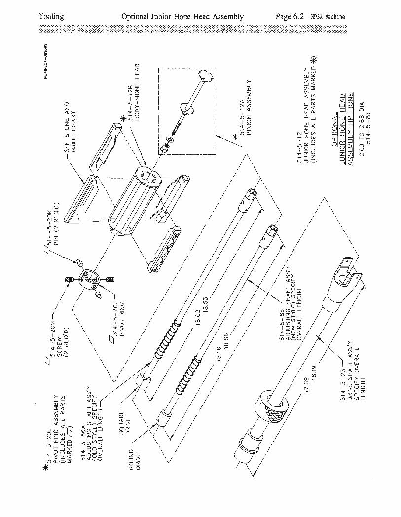
Tooling Optional Junior Hone Head Assembly Page 6.2 EP3A ilachine
ffiii:i:i+i#li#$fii*iliiliiil: iii'*:ii:iri::i:iuii,#ii*iffiii:i:iitiiii*ili:ffifiir:lir.:#il#i*iiii#i+x!:+lijiixlirii
Ax>o
r Lrldv=E6<a>2 ^ nl trJl
; E =t6ttrf .il=l a
Jltt- J <l r-r:l o-l m oe=<
=l=l.l : ;:?n Fl=l-l e+;t= Elxlsl l6
I Y ;-l Yl t'Ll o+ 1= Zlal c't6 =3 =l?l
ot!:E
mBN1rI
tr)lrl+!*6H
oodoo
I
z!
c
O:< i3rJ llN64
I
lJ)Nl-izlr)o-
r.)tr)cdD-
Od
v>N1lE
lr),rFv> //-0L ,'\ t) /\\/
trJ
Eo
LJE.
loa
'aa><lL (._c-:lL
-t -.t-
+h5a^z-
LdLu
zL)-^'til) aE- -Ldo-><:o
\l-o \I;F \
q(--
(J crtN lf) u).Jt)\
>a.JF" coEl! o_(nv))< __r, {<-
io l\ (oKzil\ PlE6o .l
|].), ltrlr=r)< Ii9oo( {-)>24 =lr) (L9>
*
ozV)2Qu.ua
oz<FtLrJ <z7sJOa yt1,.oU_uJfqo
in -La)EF LrJt!><OIa>--
U / \ /^'-u)7o<o-ila(nJ
(o(od(o-
-@
rr)N
!
rf)I
'r)
O)
do)-(ol-

Tooling Optional Minor Hone Head Assembly Page 6.3 [P3A l{acbine
iiif: , ifi ffii+lir :tiiii ii,;:,i:..:'1iiiii::li:::ir:lrii:litii:riiiliiii liiiiiii:+iliitlffiiii:iiriiiiiilr{riii:iiiiiiiiliiiiii iiii;
.Jco
=trJ(n(n
zIzo-
)-aJ>-cor5mil>U) Lt-)av)<ao<zllJOT2trJ 0-z-ln-U-oe)^i
>i;
(,Z-eFOLD.--'r i r'r7dry- r!<>ondEa<>"
rLrOUL.z/<tllGro-OOAAE.
(\@
I
U)I+
|r)
N
I
|r)II
lr)
/\6\\ /--7lvI
trJ
EoLtlE.
la
(.
of'J-l
fit?t =s'lil+l s F
Ll-lLl . I
016l-l * fil=lil g +[t tmt I
olrylEl o -UI LJI Lr)zlal -=?l
c!+I
tr)I+
6
Ld
trOozlox.
a<FtuJ<Z=9OcD4uJolJJfac)

Tooling Stone and Guide Sets Page 6.4 [P3A ilachine
FOR ROTTLER STANDARD HONE HEADA11 S.N. listed Grits andoverall stone lengths mav bemixed for quantity-breaks.-ROTTLER# DESCRTPTION
RANGE 2.7tr to. 4.l_tr
5L4-5-52-B
5L4:5-52-C
51_4-5-53-D
5L4-5-A3-E
5t 4-5-54-B
5L4-5-54-C
BANGE 3.4375il
sN100
sNL00
sN200
SN2OO
SN3OO
sN300
to 5 -75tt
80 grit,8o grit,
180 grit,180 grit,22o qrit,22o grit,
Att overall3n overall4tr overall3rr overallAtt overall3rr overall
stone
stone
stone
stone
stone
stone
length
length
lengthlength
lengthlength
length
lengthlength
length
lengthlength
5L4-5-52
5L4-5-52-A
5L4-5-53-B
51_4-5-53-C
5l-4-5-54
514-5-54-A
80 grit,80 grit,
1-80 grit,J.80 grit,22o grit,22o gri-X,
4rr overall3tr overall4tt overall3rr overallAtt overall3rr overall
sN101-
sN101
sNz01-
sNz0t_
sN30L
sN301
stone
stone
stone
stone
stone
stone

Tooling Page 6.5 fip3,1 nachine
OPTIOI-IAL SrONE AND GUIDE SSfSFOR ROTTLER STANDARD HONE HEAD(A11 orders subJect to stockavailability. )
F4NGE: .2.6q'j to 4,.25':ALL I'IzF NUMBERS -LrSggO *SUBJECT TO AVAII"ABILTTYGrits nay be rnixed f,orquantity breaks.
ROTTLER#
514-L-33
5L4-L-34
514-5-6
5L4-5-6A
514-5-8
M2T2F
M2F'3F
U2F4F
M2F5F
U2FOF
DESCRTPTTON
L20 GritL80 Grit220 Grit320 crit6O Grit

Tooling Page 6.6 [P3] uachine
OPTIONAL STONE AND GUIDE SETSFOR ROTTLER STANDARD HONE HEAD*(Al1 orders subject to stocl<availability)RANGE: 3.75rt to 5.Ott (REQUIRESPTN STONE CARRIER 5].4-1-3?)
RANGE; 4.75'r to 7.0[ (REQUIRESPTN STONE CARRTER 51_4-L-37-A)
ALL PTzF NUMBERS LISTED *SUBJECT TO AVAILABTLITYGrits may be rnixed forquantity breaks.
ROTTLER #
5L4-r.-35
5L4-L-36
5L4-5-7
51,4-5-7-A
5r,4-5-9
PT2F2F
PT2F3F
PTzF4F
PT2F6F
PT2FOF
DESCRTPTION
].2O GRIT
].80 GRIT
22O GRIT
320 GRTT
60 GRIT

Tooling Page 6.7 [P3A uachine
FOR ROTTLER JUNIOR HONE HEAD
ALL TF, UF, AND VF NI]MBERSLfSTED erits and ranges maybe nixed for quantity bleaks.
ROTTLER #
5t_4-5-1_4
5L4-5-L5
5l_4-5-16
514-5-L7
51_4-5-1_8
5L4-5-1_9
5L4-5-17-A
5L4-5-18-A
5t_4-5-1-9-A
514-5-l_7-B
51_4-5-18-B
5L4-5-19-B
TF2T
UF2F
vF2r'
TF3F
UF3F
VF3F
TF4T
UT4F
VF2F
TF6F'
UF6F
VF6F
DESCRIPTTON
L2o grit, z.ott to 2.2on
L20 grit, 2.z0tt to 2.4Ox
L2o grit, 2.4ott to 2.6g|l
1BO grit, z.Ort to z.ZOn
180 grit, 2.20tt to 2,4ltt3-80 grit, 2.4On to 2.68r22o qrit, z.ott to z.2aa
22O grlt, 2.20tt to 2.4Ot
22o griL, 2.4ott to 2.69[320 grit, z.att to z.zan
320 grit, 2.2ott to 2.40il
32o grit t 2.4ott to 2.69[
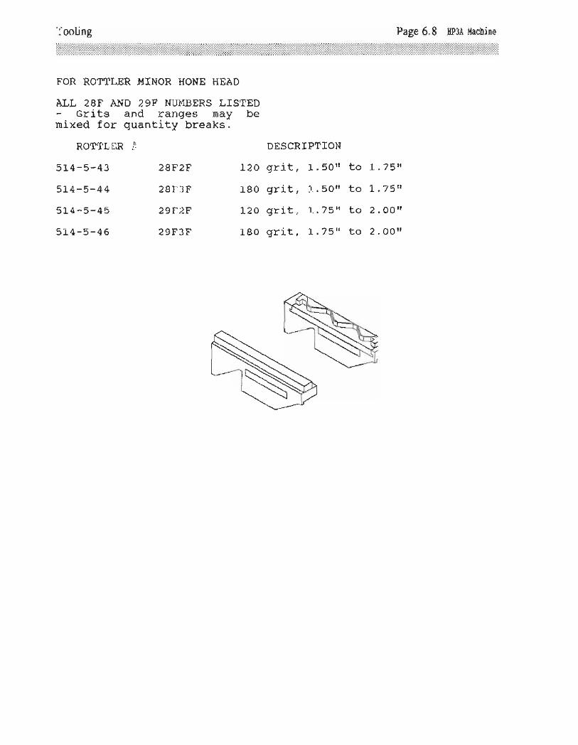
Tooling Page 6.8 [P3A uachine
FOR ROfTLER !,IINOR HONE HEAD
ALL 28F AND 29F NUI.{BERS TISTEDGri-ts and ranges mav bemixed for quantity-breatcs-.
ROTTTER #
514-5-43
5t 4-5-44
5L4-5-45
5]-4-5-46
aBF2f.
2BF3F
29?2F
29F3F
L20
t_80
L2A
L80
DESCRIPTION
grrit, 1. Eon togrit, 1.5o{ togrrit I L.7stt togrit, L.75't to
L.75n
L.75n
2. OOll
2.00il

Tooling Precision Hone Head Page 6.9 HP3A ilachine
ONZ6;-t*f-\ Jr Lrl
-i=-orrto i
>y)dsLrJ u-6a-1<?
Sdgi^J,EEx,Ul>-1-+=YF--L-lr) l==
i/
oooooI
6uzIqe
Flz
O)I
o)I+
6at
Fz6--)
:E(\J6{r(A"1.
o:'. LrJt>+-e1lr):
6trobYZtttE.t *6frsv
ol<tulrl
<gl
lflal al
qlOIu-llEIo_l
-o'u'rz-)E(r<ILdFCO
U-Nco
I
f'.I+
<ol-.OlE
o)r l-rl
i6|r)O
=LdEOa 122
N0<cO
ll!F.0ar{+;v) (n
)<(9Ooo@Jlm
N.,Fv>()o_
LTJ
E-aoa
oI
o)r)-.i6:orico
-hf
I
H.ozaJ'i7I -)rt<-J
-l+lr)o.r)
g.oFOLrJzzO<rO
=uaE_,,1!
c)117r,ru F OazY<->arYzueo<fio
F=\zFl,l*EllJ>'<*<z>YooT.E-r-O-AT{*"otrJY6
1-\O.. Lri X r,r
5'"Erfiz
oOrc
I
N,LIlt>s'--
-Etr)rf
LlJYLJ
o
FLL
=(nLrJ
E.o
/a/O/@It"I+
o6
()z.E,o_a
dqzE
nt{
--.1)F<co rLo4a€ I llJ^{'qo', l! -rt>-rqp;FFL4:|r) --i=
( ,,,
/
zo_
JLrJ
=oo
O@
I
t-'I+
EOr
;<
@
A'\P
/<t,z:Lf
*O+(Jl>(oEt>
jgx1 o
(
t_
"'l
:- \Y'lP \' <i \Lo--jn<
m()a_Zu)^I *a-<o (r:)\lf ;l-
^2rr: <=ts
zo-()zEo-0
av.tdoJoI
zE(JzEcl
l!Om
I
IttI+
OF
LrJom
i
NI+
6

Fage 6.10 Hp3A l,tachine
iii:::::iii:::::i:.:i::::::i::j'::ji::ij::::::i'.i::.::::::::.:::::ii:.::::;::::.::::::ii:::::
Tooling Stone Holder - Sleeve Sets
Sz-o_
oF@oI
NoUz-ue
LtJ
LrJLJ)U)?
.OoL!v\
><JJ:oIt- { ot&-.^| 6z
tL\ al2-=)
F=co#o-I OOr- (, Lrlrv+F-tqgHsL!
>L! >@-gI Ea
NO=iLi+ -t-o()aa (n
u i.tll /\/
i -ut-I <->
fi*^d.oO$
Y Oo,* LrJ -+
sl3;
(Jz-E.o_U)
E.I!Fu()
L!t)@
I
l--I.+
6
Lr-J
LrJL!
I,^'.)4o\f-tz-l,Y Oor(Yl* L-l *+c.r (DJiillr)
zM.o-av"LrJFu(J
)<lr)@
I
l--I+
E FLrJL/')
E.LJoJoItiJzFa
FLrl
=m@<_C)I
o) Ldlzso-Faa I
-L'Jr_!0_aIF=> LrinZ-
\i,(\:r
= r\l=
>+
&.Lrlo
{ --.t(oO
l<o)rljoa| =(\so<-F-6AO
<oL!
zE.
lr)rjtr)lt-.
N-*-
N
j
u-)
r..j
(oLJlr)
lr)N+
E"LrJm
fzFU.
o_
+I
O)I+
lr)
co+I
c')I
n-ul
O+I
O)I+
Lr)
L!N(t
--)
ai<
L!I
OI
I
l!
<oLrJ()z.
E
Oo)Or.j
Oc)O)c.i)a
rjOl.r)
f)
\rc:..)
c
o.cCd
Nr.)+OOo+
1".l(c(:+\cuic\l+
C\l
€+
O
+
cJ,
u.N
+
uLJCD
lzFv.
o_
')(o
I
O)I
(oI
o)i+
(r(o
I
OJI+
(cI
o)I+
I
o)I+
I
O)I+
I
U'I+
(cI
I
+
I(o
I
oJI
"i-f d. f
L!Na
+qI II I
v:I
ulrl
v:I
Cfo o-bN<Ld+tr0a-)_(oF\f
69l-xSI uLrl+ .t
-OOa v)a
r\- C-/lrt/p-Lsa e n-777n.?\* ////////(-
//////// ,J(

Tooling Stone Sets Page 6.11 [P3A Hachine
(/)t!zoFa+
E.
JoO
ot!E
z.LrJLrJu.(J
L!
=_)co
=o))ItJ
LdF
==
u')at!zoE-
Idd
FE.o
-)O@
)ao@
JO@
)<
NN
YoNr'')
E.LrJco
lz-Fuo_
ON
I
OJ
I+rf)
oN
I
O)I+
6
coO(\
I
o)I+
tr)
OoN
I
OJI+
tr]
ooN
I
o)I+
E
aLr.J
Z.oFa\lr)
I(\
EoJoO
OLrJt.
zLrJLdE.()
trJl)(D
=oJ-JLd
LIF
==
aaLrlzaE.
Idd
FE
)UcO
><O@
JO@
:<ONN
)<ONf')
E.LrJc0
lzFto_
@
I
OJI+
(-)
@
I
o)I+
ro
CDoI
O)I+
lr)
OoI
O)I+
Lr)
O€I
O)I+
lr)
ol<lL!l:rl
-lzlolrlzlolal()ILill0.1o_l
LJIzlolFlal

L!-tr ^_lP:X! E?H^;;=99:=t*=aa"--!-3P:o-oft' 71nfiu)zt?& 9z
=:I:E*E+(no_(n?1
\\/
oooLJ
oUJE.
z3o:clu1)u)t-<Lr.lozo-=
ILrl
ot!&.
LrJ
O
t!v.
foaoL-
zuJP[7(J
,: Lrltt-7>"20aC)oOF(J
P9r>0a L!-troF--
z.t- udo.,u:!!4)'z)EUX.OOO
OIdlLr-l I
:[lI
Lr ll-=l
' Ol .,Tl, r,l
| ,^nl-zl *l5t
=l_1"'lal al-l qlplato_l oi
_zgdL-
7<)il r..l
LrJ ->=ELdOE
Toohng Disassembly Instructions Page 6.12 HP3A uachine
\ \\\/i
{6\\b/\J
n/ ,/ |'// ,ir/ i/i
iz./ ,=</ )r)l
t )L)'a' :;F,/\ -oE e/6*"ff
)eorLd
oa>:f Ldt--E

Old Style Parts AssembliesUoner and Lower
Li rnit'Valves Adj usunent Page 7 .l EP3A !.tachine
NooooI
ztU
SET UPPER LIMIT VALVEso THERE rS 3/32" cAPBETWEEN PLUNGER BODYAND ACTUATOR VALVENUT
3/32" c^P
ADJUST BYRELEASING NUTAND TURNINGPLUNGER BODY
NOTE:MAKE ALL ADJUSTMENTSWTH HONE TURNED OFF.
ACTUATORVALVE NUT
PLUNGERBODY
f-ffi]'-"f'"w:,1""
ON OLD MACHINERIDUCE HEIGHT OFPLUNGER BODYTO 1-15/32"
ADJUST BYRELEASING NUTAND TURNINGADJUSTING SCREW
UPPTR AND LOWERLIM IT VALVES ADJUSTMEN TS
CLIPPARD VALVT
SET LOWERLIMIT VALVE SO
THERE tS 3/32" GAPBETWEEN BUMPERAND STOP, WHEN
BALL ACTUATOR ISJUST TOUCHINGADJUSTING SCREW

Old Style Parts Assemblies Pneumatic Circuit Diagram Page 7 .2 [P3A l{achine
514-2-65CLIPPARD VALVE(UPPER LtMtT)
L=f I
6d@oIr
I
t
RAM (POWERSTROKTNG)
FEED UPCYLINDER
514-2-65CLIPPARD VALVE 51 4*3-30A(LowER LtMtr) BLEED
FIXTURE
514- +-1MANIFOLD(srRoKrNG,FLOAT &CLAMP) --l
51 +-2-62VALVE (NEEDLE& CHECK, HYD.MAKE UP & BLEED)
502-1.1-35AVALVE (FLOWcoNTRoL)
514-2-61EVALVE (NEEDLESTROKING SPEEDcoNTRoL)
5i 4-2-63RESERVOIR
51+-3-26AMANIFOLD(srRorrNcSPEEDcoNTRoL)
51+-7-+AESOLENOIDvALVE (rrroour)
514-7-45CYLINDERINTERFACESENSOR
514-7-58CHECKVALVE
514-2-70ESOLENOIDVALVE(sroPSTRoKTNG)
51 4- 2-68ASTROKINGVALVE
51 4- 3-99MUFFLTR
502-11-8GUAGE
51 4- +-33MANIFOLD(ArR SUPPLY)
51 4-3-93LUBRICATOR
5t 4-7-59VALVE DWELLCONTROL
51 4-3-86AHUMPHREYVALVE (FLOAIcleue)
TUBING
AIR LIQUID3/B--+-- --r-t /+ --+-- ---+-
t /a -->--
EnYJINI -
-1>-A-T-----l
I
FA_)
I
A
cn a ^ 11JVL-Z- I I
CLAMPCYLINDER FLOAT 502-27-17
REGULATOR(RESERVOTR1s PSr)
502-11-35AVALVE (rlOWcoNTRoL FLOAT) AIR SUPPLY
'r00 PSI
502-27-17REGULATORFLOAT
i* T-li'I r*-'r-n,FrrrER/REGULATOR
HONE PNEUMATIC CIRCUITlvlTH sHoRT STROKTNG & HUMPHREY (FLOAT/CLAMP VALVE)

Old Style Parts Assemblies Drive Pinion Assembly Page 7 -3 [P3A t{achine
oaoI
U-e
N&(o>t >-
tl Lri*l voLirl _ t_-
il lo.fil 53tol ();-<l =;-lT
zz-l ts- <LJl
=*al i-)c.t^It'l co
IF!_ll ,n o2l -rzrl ! --rnl (JdLJl v--: x
ula
zol-r
=N4l(LI
'.,-,+z-tlr)0
z.L!FI
=Or-u = cDn&'J=(J^\-aazr_b:-Zt,tU)luv(\+J6 iSP
/>tsr\-\\
lL!
->i<1- trJ
-Ia(n
UJ)<
F"tO
=
N(o
I
Olf)

at-E.
>o-)co --{24<uJ -
OAtn*(/)ij^l{o.v(o. .1 /\'Ul>-r-E z'-lf)o9=
+
I
l-.
rFozUJ)
o.
LdL!, Ocolf+FF\
L..J d9>l=Eu)501-@irOt)=t)
'fi1(oJ(ott+<+
6d6
..tIIFI('tzltrJl--.rl
)<lOILrll-LtOI
6r.)
Ir?
IFOztiJJ
<o,
@\Frik<lrT' a(D-*<e{ iJ cllLJJ l(oJ(otl+<+
6ci6)C
I trll>ll!lulIJtu1
+o<lL!(oJ10-:3|r)(JJf
f.)+l-
o ql-- t4o+<U_TE rr.ra+)f
E.LrJI-'l Lr)
3=IF
.DU''rf*o<--lf)F
zlri
E.oFtL
Ia
(or.)
I
(oI+
lr)
LrJ
<Y(o^(oL.,tE
oo-O_tor
toMr.) <Ir!(o(9 u.rUJzz6a 8s-)( J.p
1,,*&|r)m
Xlst3l: d
l+>trl --i<l-bLtll-z(Jl=1
o-
Olr)Jl<(cr L!laj --.r
r-oO
E.
LrJC)
FLrJ:rOFx.
^o:Eoo N< I'-
FY (o(9 (o
keJ=lIcv -l -U)v O(/) tl)
LO
I
@Ioorr
lxl<^tl-jr')" oI *-
9LrJts+<*6d{J
_v.ro{r LrJ
(o(Jlo$2
u)v.
(')N
I(oILJ+()|r)Q
Old Style Parts Assemblies Gear Box Section Page 7 .4 [P3A l{achine
OF<t1lz
rr)IY+O
-C)lJ) _J
IJN t!.1co Lr.irf
.o=
d@
doo
I
6U2rUG
rtrgAN<r; F g T T ?=atsehi
?- +H ig ifrFzq?ma's +E +E
H? *5 *fr;s ffi s5*E5;*;=
,;zv
-g^ o5|J.)-o NEluh Iooreil 9 *!1n +t
- l^r eU
'bf:) Lrlo
O
t+\f/) F
l-@FrU-+<
-Ito v)
Fz5)
NJr+<rA,offir>
=l;Lnl
rd@:<<fo1)-
('o-'U
<-._-Elr)o
z-!Y^u, r OJ=i3Jo'- 01<-|r) COr)
r--6ry^ot LJJ
e.r -ftrPL-l-v(O !-+:T-0.L!no(J
r)raJt<r) Ld1a
j--.rtr)o
(oc.l
I
(oI+
tr)
+I
olr)
l-.N
I(oI+
6
Ld
E.ozozo_
El!=- (f)
!f<t=
t/)l:<t+O
FOtr)J
E.trJIaN<
T=@FN(,rfC,EOT
E.bJzFLJE.
uctr rO
:Ql')T
+lr)Jt<(o trl1@j--r
'r)o
o)+lc>
-Lutr)O
co(J> <rr(9 cJ0<(J-.2-r -<2. c'J<z')(,E Tq6 N!li;!-2 rv- lei?6H ?e6 90.6*t* *E- ;9"
O
+N
,
OOr.r)
F
=z.:<(_)oJ
,,iE.co
JJ
m

Old Style Parts Assemblies Carriage FloatiClamp Page 7 .5 fiP3A l{achine
o_
-J
FoJL-
a
ooI
Nou?u&
rC 5a9o-o lt+lJl-
*sE i=:ENL,J* o).?c.r3 ds rf) (J vv
&ilg+<rE-:tLo()
lL,L
9sNdIr)Flz+o
-Ef) L_ 31!@ a b:-frf; ,{gI -)e IcrlJ* +>oo^, Jt-trori) 'r)Y
co(oN6
J.,3ar>+><-LrJJlr))<()
mE+<l-^n. .0-rli>+-"<
-fJ'r)()(J
L!lcit<lrIrl<l(-)l
lr)r-)
Io>O trlt):<
tLrJu)ia
I ^--(o(ry
rvu
O-e.tr\ o_ \,mlr)
z<9l-* Fol:)lmnI:E+ (/)
-:l()o_
(D(o€Er9t) FrO-:Alr)<
o-
(olm(Ja\lu-?crkl. /,o:EJlf) >3
><L!
{DN
x.@
o_
JIJ
@l
f*)I+
6
E.t!FL
oLoo-
o3^P t,o-lo' .r E- LrJ
+9*63s
LJ__JFat<foz-
g.aFo-LL>IJac)
lr)I
t-)I+
lI]
(O
T-s.- (Jr) LrJl-TNdAorS
U]FJ
v.UJE
UJF-)o-
E.tto(J
mO)N
I
v)I+
U) t!FJo-
G.td
oO
ot)
I
t)I.f
rO

Old Style Pafts Assemblies Sftoking Cylinder Page 7 .6 [P3A Hachine
oooI
zrd
51 4-3-',r2ASTOP ROD
514-2-65VALVE(LOWERLttil tr;
51 4-3-1 0AsToP (LOWERLrMrT)
51 4- 2-39ADJU STABLEHANDLE
51 4- 4-90AROD &
UPPER PISTONASSEMBLY
514-2-60DUST SEAL
(RoD)
51 +-2-67BALL ACTUATOR
(vALVE)
51 +-2-52O_RING
(ROD SEALUPPER)
514-7-37 AO_RING
(cAP SEAL)
51 4-4-89cnr (ueeen
CYLTNDER)
51 4-2- 50O_RING(PrsToN
SEALUPPER)
514-2-52O_RING
ROD-PISTONSIAL
51 4-2-52o-RrNG (RoDINSERT SEAL)
5i4-3-J0AB LtED
FIXTURI
51 4- 4-77O-RINGBUMPER
B+T514-1-178SPRTNG (SrOeROD)
514-8-2UPPERCYLINDER
51 4-8-3cre (rowtR
END)
51 4- 8-9O_RING(CYLINDTRsEnl)
514-4-864INSERT(cYLINDER)
51 4-8-1LOWER CYLINDER
51 4-8-1 0O-RING(PrsToN sEALLOWER)
51+-8-+PISTON LOWER
514-8-9AO_RING(CYLTNDER SEAL)
111=','-'
STRCKING CYLINDTRCLIPPARD VALVE

Old Style Parts Assemblies Upper Limit Valve Page 7 .7 [P3A l,tachine
NooPIo
zruG 514-+-64A
PIVOTSUPPORT
51 +-4-66SIDE COVER
(UPPER LrMtrvelvr)
514-2-65VALVE
(UPPERLrMrT)
514- +-ENCLOSURE
(LrMrT vALVE)
514- +-NUT
ACTUATOR(vALVE)
51 4- 4-698PLUNGER
1 /2-zouNFJAM NUT
51 4-4-688PLUNGER
BODY
51 4- 4-68ASPRING
fi4-+-A4SNAP RING
51 4- 4-90AROD & UPPERPISTON ASS,Y
51 4- 3-7DPrN -(UPPER
PrvoT)
JAM NUT D +l51 +-3-12ASTOP ROD
LOCKNUT
51 4-4-63ABUMPER
51 4-4-62ACAP
514- 4-61 A
UPPER PIVOTASS,Y
51 4-4-61 B
SPACER
51 4-4-63ABUMPER
ADJUSTING SCREW(LowtR LrMrr VALVE)
UPPER LIMIT VALVI &UPPTR PIVOTCLIPPARD VALVE
514-+-648PIVOTSUPPORT
51 4-2-39CADJUSTABLEHANDLE
1 00-1 9THRUST
514-2-438SPACERADJUSTABLEHANDLf
51+-2-398EXTENDERADJUSTABLEHANDLE
D+J
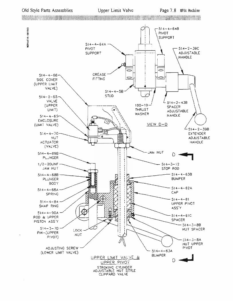
Old Style Parts Assemblies Upper Limit Valve Page 7.8 EP3A !,lachine
ooOoIa
U2Ire
51 4-4-648PIVOTSUPPORT
5'14-4-64APIVOTSUPPORT
GREASEFITTING
514-2-39CADJUSTABLEHANDLE
514-+-66SIDE COVER
(ueern rurrvalve)
51 4- 2-65VALVE
(UPPERuMlT)
51 4- +-6ENCLOSURE
(LrMrT vALVt)
514-+-70NUT
ACTUATOR(vALVE)
51 4- 4-698PLUNGER
t /z-zounrJAM NUT
51 4-4-688PLUNGER
BODY
51 4- 4-68ASPRING
514- 4-84SNAP RING
514-4-90AROD & UPPERPISTON ASS,Y
514-3-7DPrN-(UPPER
Pr vor)
51 4- 4-58STUD
1 00-1 ITHRUSlWASHER
51 4-2-438SPACERADJUSTABLEHANDLE
VIEW D_D51 4- 2-398EXTENDERADJUSTABLEHANDLE
D+l-12ROD
LOCKNUT
ql r'-- -1
STOP
51 4-4-63ABUMPER
51 4-4- 638BUMPER
51+-4-62ACAP
51 4-4-61UPPER PIVOTASS'Y
51 4-4- 61 C
SPACER
51 4-3-88NUT SPACER
51 4- 5- 8ANUT UPPERPIVOTADJUSTING SCREW
(LowER LrMrr VALVE)
UPPER LIMIT VALVE &UPPER PIVOT
STROKINC CYLINDERADJUSTABLE NUT STYLE
CLIPPARD VALVE
D+J

Old Style Parts Assemblies Pneumatic Power Supply
zoF
E.X3P Er { r.rJj,o :lE+cl uJ.- -) trJlr)J a
=UJ^u$CJ\a oEt-zLil=JJ+-r --.r If,i;=
B=--<r,OYrO-:.. Er F<:0ftu)(nE
oooooI
63.h>tE
Lrl
0t LIJoF0_<ooYn0auLdm..F:lrJr
tZ--^-\J-Fr!Fa<0
t:- I,/l
llo_lo_lrlal
I
KIL-LJl
=lCIo_l
\JF
_l[JZn_
)!oPI
^)+ru?.!,zt;{3
U)()Atr/) < :-o)-i)<r(9:Et=<
-vLrlQ6E.
RXor:l<
rt)EJItll+t(J
-JL-loIo<
@I
f u.rr(J&<o:l.r)(J
-6'---J o-o-^o_:0:-
E.a


665554 PAGE 1 0F 4
MOB]L OIL CORPORATION MATERIAL SAFETY DATA BULLETIN
****x**x**;lx********x I. PRODUCT IDENTIFICATION *x*x***x************i"IOBILIIET UPSILON
SUPPLIER: HEALTH EPIERGENCY TELEPHONE:MOBrL OrL CORP. ( 212l' 883-441i
CHE}IICAL NAMES AND SYNONYMS: TRANSPORT EMBRGENCY TELEPHONEPET. HYDROCARBONS AND ADDTTTVES (800) 424-9300 (CHEMTREC)
USE OR DESCRIPTION:CUTTING FLUID
****X****X* II. TYPICAL CHEMICAL AND PHYSICAL PROPERT]ES **********X
APPEARANCE: ASTM 5.0 LIQUID ODOR: MILD PH: NAVTSCOSITY AT 100 F, SUS: 62.0 AT /i0 C, CS: iA.2VISCOSITY AT 21,0 F , SUS: 35. 1 AT 100 C, CS: 2,7FLASH POrNT F(C ) : >325 ( 163 ) (ASTM D-92)MELTING POINT F(C): NA POUR POINT F(C): 30( -i )
BOILING POINT F(C): ) 600( 316)RELATIVE DENSITY, 75/4 C: 0.849 SCLUBILiTY IN WATER: NEGLIGIBLEVAPOR PRESSURE_MM HG ZOC: < .1
NA=NOT APPLICABLE NE:NOT ESTABLISHED D=DECOMPOSESFOR FURTHER IIIFORMATION, CONTACT YOUR LOCAL MARKETING OFFICE.
x**x*x************x****xx III. INGREDIENTS **X*****************XX*XXWT PCT EXPOSURE LIMITS SOURCES
(APPROX } MG/}13 PP}l {AND NOTES )
HAZARDOUS INGREDIENTS :
NONE
OTHER INGREDIENTS:REFINED MINERAL OILS >95ADDITIVES ANDi OR OTHER INGREDS. < 5
I(EY TO SOURCES: A=ACGIH-TLVr AX=$g6GESTED-TLV, M=MOBIL, O=OSHANOTE: LIMITS SHOWN FOR GUIDANCE ONLY. FOLLOW APPLICABLE REGULATIONS.
***x*x*******xx*x***x IV. HEALTH HAZARD DATA ******X**********XXX*
THRESHOLD LIMIT VALUE: 5.OO MGIM3 SUGGESTED FOR OIL MISTEFFECTS OF OVEREXPOSURE: PROLONGED REPEATED SKIN CONTACT WITH LOW
VISCOSITY O]LS MAY LEAD TO IRR]TATION CAUSED BY D]SSOLVING OF THENATURAL OILS FROM THE SKIN. SLIGHT SKIN IRRITATION.
**X**XX**X*XXX V. EMERGENCY AND FIRST AID PROCEDURES ****X***X*****
EYE CONTACT: FLUSH WITH WATER.SKIN CONTACT: WASH CONTACT AREAS WITH SOAP AND WATER.INHALATION: NOT EXPECTED TO BE A PROBLEM.INGESTION: DO NOT INDUCE VO},I]TING. ADM]NISTER VEGETABLE OIL. GET
MEDICAL ASSISTANCE. (NOTE TO PHYSICIAN: IVIATERIAL IF ASPIRATEDTNTO THE LUNGS MAY CAUSE CHEMICAL PNEUMONITIS. TREAT APPROPRIATELY)

}IOBIL].IET L'PSILON 66555+ PAGE 2 OF 4
**xx**x**xxxxxxx \r. FrRE A\D E\PLOSTON HAZARD D-{'f.\ *XX*XX*X*X:i****xFLASH PCINT F(C): > '3't) { 16:i) (AST}I D-92)FLAX}IABLE LII\IITS . LET,: ,6 UEI-: 7 . LT
EXTII\TGUISHING IIEDIA: IIARBON DIOXIDE, FoAlt, DRy CHEIjIC.\L AliD WATER FoG.SPEC]iAL FIRE F'IGHTI}tG PRCCEDURES: FIREFiGHTERS :-Ji-ST USE SELF-CONTAINED
BREATHIIiG .\PPARATI,TS .
UNUSU.I'L F.IRE A}'JD E\PLOSION HAZARDS: NoiTjEIJFPA HAZARD ID: HEALTH: 0, FLAMMABILITl': 1, REACTITiITi: 0
x***xx*x**x*x**x**tx*xx vII. REACTIVITY DATA *XXX*X*****X**X*****X**STABILlTY (THER}iAL, LIGHT, ETC. ) : STABLE
COr\DITIONS TO AVOID: EXTREI1E HEATINCOIIPA'| IBILITY ( I'{ATERIALS TC AVOID ) : STRONG O,{IDTZERSHAZ,,\RDOUS DECOIIPOSITIO,\,i PRODUCTS: CARBCII !'IONOXiDF .
HAZARDOIJS POLY}lERIZATION: WILL NOT O(]CUR
x*****x**x***xx.***x VIII. SPILL OR LEAK PROCEDURE x***x***x**x******EN\TIRCN}IENTAL I}IPACT: REPORT SPILLS AS REQLTIRED TO .{trPROPRIATE
AL]THORITIES. L. S. COAST GL;ARD REGULATTONS REQUIRE I.\I}IEDIATI;REPORTING OF SPILLS THAT COULD REACH ANY IIATERI'AY INCLUDINGIi'ITER}IITTE\T DRY CREEIiS. REPORT SPILL TO COAST GUARD TOLL FREENU}IBER 8OO- 421-BBO2.
PROCEDLRES IF }IATERIiL IS RELEASED OR SIJILLED: ADSORB ON FIRE RETARDANTTREATED SAIIDUST, DIATOYIACEOUS EARTH, ETC. SHOVEL UP AND DISPOSE OFAT Ai.I APPROPRIATE iiASTE DISPOSAL FACILITY IN ACLTORDANCE WITHCURRENT APPLiCABLE LAK'S AND REGLILATIONS, A]'JD PRODUCTCHARACTERISTICS AT TIl'iE OF DISPOSAL.
WASTE MANAGF.}IENT: PRODLICT IS SUITABLE FOR BURNI}iG IN A}i E\ICLOSED,CONTRCLLED BURNER FOR FUEL VALUE OR DISPOSAL BY SUPERV]SEDiNCINERATION. SUCH BURNING }IAY BE LI}lITED PURSUANT TO THE RESOURCEco\sER\,-ATioN AliD RECOVERY ACT. IN ADDITIO]i, THE PRODUCT iSSUITABLE FOR PROCESSING BY AN APPROVED RECYCLING FACILITY CR CAN BEIISPCSED OF AT ANY GOVERN}IENT APPROVED WASTE DISPCSAL FACILITY.USE OF THESE }IETHODS iS SUBJECT TC USER CO}TPLIANCE I{ITH APPLICABLELAWS AND REGULATIONiS AND CONSIDERATION OF PRODUCT CH.{RACTERISTICSAT TIIIE OF DISPOSAL.
**X*XX**X**X*X** IX. SPECIAL PROTECTION INFORMATION *XX****X**X*X*X**EYE PROTECTION: NO SPECIAL EQUIPMENT REQUIRED.SKIN PROTECTION: IF PROLONGED OR REPEATED SKIN CONTACT IS LIKELY, OIL
IIIPERVIOUS GLOVES SHOULD BE WORN. GOOD PERSONAL HYGIENE PRACTICESSHOULD ALWAYS BE FOLLOWED.
RESPIRATORY PROTECTION: NO SPECIAL REQUIREMENTS UNDER CRDINARYCONDITIONS OF USE AND WITH ADEQUATE VENTILATION.
VENTILATION: NO SPECIAL REQUIREMENTS UNDER ORDINARI CONDITIONS OF USEAND WITH ADEQUATE VENTILATION.
*x*x**xxx*x*x****xx*xx x. SPECIAL PRECAUTIONS ***X***X*Xx*XX*X*X****STORAGE: SEE APPENDIX FOR PRECAUT]ONARY LABEL. CL_402

:'lOB I Li\1ET UPS I LON 665554 PAGE 3 OF 1
***xxx*****xx*xx*xx*** xr. Toxrcoi,ocrcAL DATA x*x*xx*x*******xx****x---ACUTE_--
ORAL TOXICITY (RATS): LDSO: ) 5 C/XC SLIGHTLY TOXIC(ESTIMATED)BASED ON TESTTNG OF' SiMTLAR PRODUCTS AND/OR THE ColtpoNElirs.DER}IAI, TOXICITT' (RABBITS ) : LD50: > Z C/t;C SLIGHTLY TOXIC (ESTIIIATED ) __BASED ON TESTING OF SI}IILAR PRODUCTS AND/OR THE COMPCNENTS.INHALATION ToxrcrTY (RATS): LC50: )5 MG/L FoR 4 HRS . 0/Ia RATS DrED.A'T THIS DOS.{GE LEVEL. PRACTICALLY NONTO.{ICEYE IRRITATION (RABBITS): CAUSED NO SIGNIFICANT IRRITATIoN To RABBITS.EYE rRRrrATroN scoRES: 2,3 AT 1 HouR, 0.1 AT 24 HouRS, 0 AT 7DAYS.
SI(IN IRRITATIOl\ (RABBITS ) : SLIGHTLY IRRTTATING To RABBITS . PRI}1.{RYlRRITATICN SCORE : 1,6/8---OTHER DATA-_-X*XXXTHIS }IIXTURE OR A SIMILAR MIXTURE DID,'{OT RESULT IN ANY F.{TALITIESTO RATS AT CONCENTRATIONS ( SEE INHALATION TOXICITY ABOVE )SUBSTANTIALLY HIGHER THAN THE 5 MGl}13 TLV SLIGGESTED FoR oIL MISTS.
*****x**x***x****x** l{II. REGULATORY INFOR}IATION **x**x*x**x***x*x*xxTSCA TNvENTORY STATUS: ALL cot'ipoNEl\irs REcrsrERED.D. O. T. SHIPPING \iAryE: IJOT APPLICABLED,O.T. HAZARD CLASS: NoT APPLICABLEUS OSHA HAZARD COI"IMUNlCATION STANDARD: PRODUCT ASSESSED IN ACcoRDANCEh'ITH OSHA CFR 1910.1200 AND DETERMINED TO BE HAZARDOUS.RCRA rNFoRllATroN: THE UNUSED PRODUCT, rN ouR oprNroN, rs \to,rSPECIFICALLY LISTED BY THE EPA AS A HAZARDOUS WASTE (+O CFR,PART 261D); DOES NOT EXHIBIT THE HAZARDoUS CHARACTERISTICS oFIGNITABILITY, CORROSIVITY, OR REACTIVITY, AND IS NOT FOR}IULATEDI{ITH THE }IETALS CITED iN THE EP TOXICITY TEST. HCWEVER, USEDPRODUCT MAY BE REGULATED.
THE FOLLOWING PRODUCT INGREDIENTS ARE CITED ON THE LISTS BELOII:
CHEi"IICAL NAME(orL Plrsr )
1 = OSHA Z,6 = EPA CARC,
11 = IL RTK,i6 = FL RTK,
KEY TO2 = ACGIH, 3i - NFPA 49, g
72 = MA RTI(, 13LI = PA RTK.
CAS NU}IBER LIST CITATIONS2,10,11
LIST CITATIONS=IARC, 4 =NTP, b=NCI,= NFPA 325M, I = DOT HMT, 10 = CA RTK,= MN RTK, 14 = NJ RTK, 15 = MI Zg3,
*x**x******xx*************x********x***x*x*x***x*x***********x*****x****INFORMATION GIVEN HEREIN IS OFFERED IN GOOD FAITH AS ACCURATE, BUTWITHOUT GUARANTEE. CONDITIONS OF USE AND SUITABILITY OF THE PRODUCT FORPARTICULAR USES ARE BEYOND OUR CONTROL; ALL RISKS oF USE oF THE PRoDUCTARE THEREFORE ASSU},IED BY THE USER AND WE' EXPRESSLY DISCLAIM ALLI$FIiNIIE!, -o-r e vERy KrND AND- .r.-r.ATuRE-, Iiv-qr,-uo-lN-_c. wlnn[xiir--s'-o'.r"*=l{EECgSNTrei-i"ir-x .q,rr.o-. rirNC-s-,s.po-n A p-ARriCu.r,ep- euRposE i*--frs5Fecr ro rHERECOMMEND.ATioN'-Fon" usrs-wriiCH-inrnrNcr-vrlrn pATENTS oR AS EXTENDTNGLICENSE UNDER VALID PATENTS. APPROPRIATE WARNINGS AND SAFE HANDLINGPROCEDURES SHOULD BE PROVIDED TO HANDLERS AND USERS.

4
x*
**
*vt4
}iOBILMET UPSILON 665554 PAGE.i OF*******x*x******xx*xx*xx*x***xxx*xx*x*****xx**x*x**xx*xx**xxxx*xxxxx**PREPARED BY: }ioBIL oIL CORPORATIOI{
ENViRONIIENTAL AFFAIRS AND TOXTCOLOGY DEpARTlrElir, PRTNCETON, NjFOR FURTHER INFORI"IATION, CONTACT:}lOBIL OIL CORPORATION, PRODUCT FOR}IULATIOII A}JD QUALITY CONTROLtoo:rztr uai,LOIiS ROAD, FAIRFAX, VA ZZ0S? (203 i g49_3265
x * x x * * * x * * r* x * * * * x * * x * x * * * x * * * AppENDIX X * * * X * * X * * * * * * * * * * * * * * * * x * x xFoR MoBrL usE olily: (FrLL No: irrJi54xltzOt) IIHC: 1x 1x 0 0 1 ppEC:US86-089 AppROtiE REVISED: 0,i /78/g6* * * * * x x *'* x x * x t * * *x*'( * * x * x * x * x * x x * * * x * * x * * * * * x * x * * * * x x x x * * * * * * * * x x * * x * xPRECAUTIONARY LABEL TEXT FOR PACKAGED PRODUCTS:
CONTAINS LOW VISCCSITY OIL
CAUTION
}IAY CAUSE SI.IN IRRITATION O}I PROLONGED,REPEATED SI(II] CONT.{CT.
AVOID PROLOTIGED OR REPEATED C'ONTACT THATCOULD DEFAT T}iE SI{IN.WASH SIiIN CONTACT AREAS WITH SOAP AND WATER.
LAUNDER CONTAMINATED CLOTHING BEFORE REUSE.AVorD wEARrtic oF cLorHrNG soAI{ED i{irH FLUTD.AVOID PROLONGED INHALATION OF MISTS OR VAPORS.
WHEN USE CONDITIONS ARE LIKELY TO RESULT TNEXCESSTvE MrsrrNG {cREATER rsr$ 5 MG/iu3).pRovrDE ADEQUATE LocAL vrntrl.qdroN oRRESPIRATORY PROTECTION .
FOR I}IDUSTR]AL USE ONLYNor TNTENDED oR surrABLE pon udrrN oR ARoUND A HousEHoLD oR owdli.ruc.
ATTENTIOTi
EMPTY CONTAINERS MAY CONTAIN PRODUCT RESIDUE, INCLUDINGFLAMMABLE OR EXPLOSIVE VAPORS. DO NOT CUT, PUNCTURE oRWELD oN oR NEAR coNTATNER. ALL LABEL wenliiucs RNo pRE-CAUTICNS MUST BE OBSERVED UNTIL THE CONTAINER HAS BEENTHOROUGHLY CLEANED OR DESTROYED.
REFER TO PRODUCT MATERIAL SETTT]Y' DA'IA BULLETINFOR FURTHER SAFETY AND HANDLING INFORIIATTON.
MOBIL OrL coRpoRATrON, NEW YORKI *.U. 10017 cL-40 2(7/86j*******x*x*****************x****x***tx*xfxxxx**x**********x*r*x****x**x.O.T. SHIPPING NAME: Nof APPLlCABLE.O.T. HAZARD CLASS: NoT APPLICABLE
*DD