
Hoshizaki-HD)_pts.pdf · 4a T2 Screw 4×8, SS 7P32-0408 5 5 5 5 5 Cover – UL, Rear GS 2A0956-01 1...
71
Hoshizaki “A Superior Degree of Reliability” www.hoshizaki.com Models RH1-AAC(-HD) RH2-AAC(-HD) RH3-AAC(-HD) SafeTemp Series Refrigerated Kitchen Equipment Hoshizaki America, Inc. Number: 71178 Issued: 8-30-2000 Revised: 9-9-2010 PARTS LIST
-
Upload
nguyennguyet -
Category
Documents
-
view
212 -
download
0
Transcript of Hoshizaki-HD)_pts.pdf · 4a T2 Screw 4×8, SS 7P32-0408 5 5 5 5 5 Cover – UL, Rear GS 2A0956-01 1...

Hoshizaki
“A Superior Degree of Reliability”
www.hoshizaki.com
Models RH1-AAC(-HD)RH2-AAC(-HD)RH3-AAC(-HD)
SafeTemp SeriesRefrigerated Kitchen Equipment
Hoshizaki America, Inc.
Number: 71178Issued: 8-30-2000Revised: 9-9-2010
PARTS LIST
2
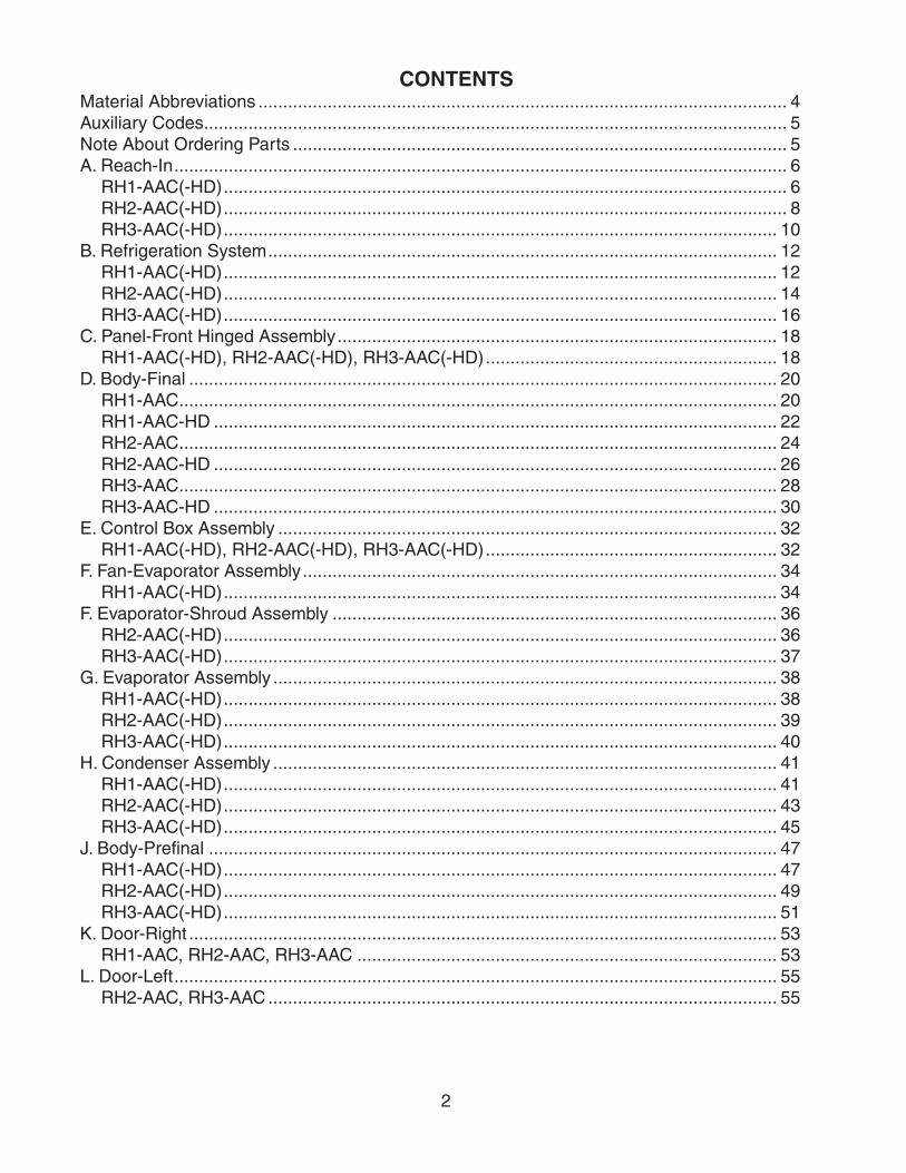
CONTENTSMaterial Abbreviations ........................................................................................................... 4Auxiliary Codes ...................................................................................................................... 5Note About Ordering Parts .................................................................................................... 5A. Reach-In ............................................................................................................................ 6
RH1-AAC(-HD) .................................................................................................................. 6RH2-AAC(-HD) .................................................................................................................. 8RH3-AAC(-HD) ................................................................................................................ 10
B. Refrigeration System ....................................................................................................... 12RH1-AAC(-HD) ................................................................................................................ 12RH2-AAC(-HD) ................................................................................................................ 14RH3-AAC(-HD) ................................................................................................................ 16
C. Panel-Front Hinged Assembly ......................................................................................... 18RH1-AAC(-HD), RH2-AAC(-HD), RH3-AAC(-HD) ........................................................... 18
D. Body-Final ....................................................................................................................... 20RH1-AAC ......................................................................................................................... 20RH1-AAC-HD .................................................................................................................. 22RH2-AAC ......................................................................................................................... 24RH2-AAC-HD .................................................................................................................. 26RH3-AAC ......................................................................................................................... 28RH3-AAC-HD .................................................................................................................. 30
E. Control Box Assembly ..................................................................................................... 32RH1-AAC(-HD), RH2-AAC(-HD), RH3-AAC(-HD) ........................................................... 32
F. Fan-Evaporator Assembly ................................................................................................ 34RH1-AAC(-HD) ................................................................................................................ 34
F. Evaporator-Shroud Assembly .......................................................................................... 36RH2-AAC(-HD) ................................................................................................................ 36RH3-AAC(-HD) ................................................................................................................ 37
G. Evaporator Assembly ...................................................................................................... 38RH1-AAC(-HD) ................................................................................................................ 38RH2-AAC(-HD) ................................................................................................................ 39RH3-AAC(-HD) ................................................................................................................ 40
H. Condenser Assembly ...................................................................................................... 41RH1-AAC(-HD) ................................................................................................................ 41RH2-AAC(-HD) ................................................................................................................ 43RH3-AAC(-HD) ................................................................................................................ 45
J. Body-Prefinal ................................................................................................................... 47RH1-AAC(-HD) ................................................................................................................ 47RH2-AAC(-HD) ................................................................................................................ 49RH3-AAC(-HD) ................................................................................................................ 51
K. Door-Right ....................................................................................................................... 53RH1-AAC, RH2-AAC, RH3-AAC ..................................................................................... 53
L. Door-Left .......................................................................................................................... 55RH2-AAC, RH3-AAC ....................................................................................................... 55

3
M. Door-Half (UR) ................................................................................................................ 57RH1-AAC-HD, RH2-AAC-HD, RH3-AAC-HD ................................................................... 57
N. Door-Half (LR) ................................................................................................................. 58RH1-AAC-HD, RH2-AAC-HD, RH3-AAC-HD ................................................................... 58
P. Door-Half (UL) .................................................................................................................. 59RH2-AAC-HD, RH3-AAC-HD .......................................................................................... 59
Q. Door-Half (LL) ................................................................................................................. 60RH2-AAC-HD, RH3-AAC-HD .......................................................................................... 60
R. Mullion-Horizontal ........................................................................................................... 61RH1-AAC-HD .................................................................................................................. 61
S. Mullion-Vertical ................................................................................................................ 62RH2-AAC, RH3-AAC ....................................................................................................... 62
T. Mullion-Cross ................................................................................................................... 64RH2-AAC-HD, RH3-AAC-HD .......................................................................................... 64
U. Mullion-Tee ...................................................................................................................... 66RH3-AAC-HD .................................................................................................................. 66
V. Label Location ................................................................................................................. 68RH1-AAC(-HD) ................................................................................................................ 68RH2-AAC(-HD) ................................................................................................................ 69RH3-AAC(-HD) ................................................................................................................ 70
W. Literature & Packaging.................................................................................................... 71RH1-AAC(-HD), RH2-AAC(-HD), RH3-AAC(-HD) ........................................................... 71

4
Material AbbreviationsALUMINUM AL = Aluminum
COPPER CU = Copper
PLASTIC ABS = Acrylonitrile -butadiene - styrene AC = Polyacetal EVA = Ethylene vinyl acetate PA = Polyamide = Nylon PC = Polycarbonate PE = Polyethylene PES = Polyester PETP = Polyethylene terephthalate = Tetlon PP = Polypropylene PS = Polystyrene PTFE = Polytetrafluoroethylene = Teflon PUR = Polyurethane PVC = Polyvinyl chloride
RUBBER VN = Vinyl Nitrile EPDM = EP rubber NBR = Nitrile butadiene rubber NR = Natural rubber NP = Neoprene SI.R = Silicone rubber SY.R = Synthetic rubber EPH = Epichlorohydrin
STEEL GS = Galvanized steel SS = Stainless steel PS = Plated steel PAS = Primed steel
AUXILIARY CODEK-0 Designates the year. "K" indicates the year 2000. Years progress or regress in alphabetical order. "J" is 1999, "L" is 2001, "M" is 2002, and so on. The letters "I" and "O" were skipped. Designates significant part changes within the same year for this model. Base is 5 (0 for codes L-0 and earlier) and this number advances for each change.
Example: P-6 "P" indicates 2004. "6" indicates the first significant part change for 2004.

5
Auxiliary Codes
RH1-AAC K-0 June 2000 K-1 October 2000 L-0 December 2000 L-5 February 2001 M-5 December 2001 M-6 July 2002 M-7 August 2002 N-5 December 2002 N-6 January 2003 P-5 December 2003 P-6 October 2004 P-7 November 2004 Q-5 December 2004 RH1-AAC-HD K-0 May 2000 K-1 November 2000 L-0 December 2000 L-5 March 2001 M-5 September 2002 N-6 January 2003 P-5 January 2004 P-6 October 2004 Q-5 January 2005
RH2-AAC K-0 June 2000 L-5 February 2001 M-5 December 2001 M-6 July 2002 M-7 August 2002 N-6 January 2003 P-5 December 2003 P-6 October 2004 P-7 November 2004 Q-5 December 2004
RH2-AAC-HD K-0 May 2000 L-5 February 2001 N-5 December 2001 N-6 February 2003 P-5 December 2003 P-6 October 2004 Q-5 January 2005
RH3-AAC K-0 November 2000 L-0 February 2001 L-5 March 2001 M-5 March 2002 M-6 July 2002 M-7 August 2002 N-5 December 2002 N-6 March 2003 P-5 December 2003 Q-5 January 2005 RH3-AAC-HD K-0 August 2000 N-6 July 2003 Q-5 February 2005
Note About Ordering PartsMost assemblies cannot be ordered as complete units; parts in the assemblies generally must be ordered separately.

6
A. Reach-InRH1-AAC(-HD)
K-0, K-1, L-0, L-5, M-5, M-6, M-7, N-5, N-6, P-5, P-6, P-7, Q-5
B B1 B2 B3
4a4
5a57a
76
1a1
2a2 11 12
10
E E1
CC1
C2
C3
8a8
9a9
3a3 3b 3c 3d
D
V

7
Title: A. Reach-In Model: RH1-AAC(-HD)
Index No. Description
Material or Model Number Part Number
Required Number
K-0 K-1 L-0
L-5 to
N-5
N-6 to
Q-5
B Refrigeration System Refrigerator 1A0502A01 1 1 1 1
B1 Bolt Assembly 8×45 437889-01 5 5 5 5
B2 Truss Head Screw 5×25, SS 7C32-0525 2 2 2 2
B3 Washer 5 7W22-0500 2 2 2 2
C Panel – Front Hinged Assembly - 3A1670A01 1 1 1 1
C1 Truss Head Screw 4×8, SS 7C32-0408 2 -
Clevis Pin - 8907-0102 2 2 2
C2 Cotter Pin - 8907-0103 2 2 2
C3 Flat Washer - 4A0655-03 2 2 2
D Body – Final RH1-AAC 1A0299A04 1 1 1 1
RH1-AAC-HD 1A0360A02 1 1 1 1
E Control Box Assembly - 2A1842A01 1 1 1 1
E1 T2 Screw 4×8, SS 7P32-0408 3 3 3 3
V Label Location RH1-AAC 2A1042A07 1 1 1 1
RH1-AAC-HD 2A1042A06 1 1 1 1
1 Gusset – Frame GS 3A1520-01 1 1 1 -
4A2845-01 1
1a T2 Screw 4×8, SS 7P32-0408 4 4 4 4
2 Frame-side Top GS 2A1803-01 2 2 2 2
2a Truss Head Screw 5×10 7C32-0510 8 8 8 8
3 Panel – Side, Top AL 2A1800-21 2 2 2 2
3a Truss Head Screw 5×10 7C32-0510 6 2 2 2
3b Taper Collar SS 4H0171-01 2 2 2 2
3c Countersunk Screw 5×20, SS 7C42-0520 2 2 2 2
3d T2 Screw 4×8, SS 7P32-0408 4 4 4
4 UL – Cover Assy Top - 2A1305G02 1 1 1 -
GS 2A2757G02 1
4a T2 Screw 4×8, SS 7P32-0408 5 5 5 5
5 Cover – UL, Rear GS 2A0956-01 1 1 1 -
2A2752-01 1
5a T2 Screw 4×8, SS 7P32-0408 4 4 4 4
6 Power Cord - 4A0520-01 1 1 1 1
7 Wire Clamp - 4A0809-02 1 1 1 1
7a T2 Screw 4×8, SS 7P32-0408 1 1 1 1
8 Cover – Connector Wire GS 3A1678-01 1 1 1 1
8a T2 Screw 4×8, SS 7P32-0408 2 2 2 2
9 Cover – Wire GS 3A1679-01 1 1 1 1
9a T2 Screw 4×8, SS 7P32-0408 3 3 3 3
10 Bracket – Hinge GS 4A2306-01 2 2 2 2
11 Insert – Threaded M5 4A0407-01 4 4 4
12 Bracket – Control Box GS 4A2467-01 1 1

8
A. Reach-InRH2-AAC(-HD)
K-0, L-5, M-5, M-6, M-7, N-5, N-6, P-5, P-6, P-7, Q-5
B B1 B2 B34a4
5a5
7a
76
1a1
2a2 10 12
E E1
CC1
C2
C3
8a8
9a9
3a3 3b 3c 3d
D
V
1b
11 11a

9
Title: A. Reach-In Model: RH2-AAC(-HD)
Index No. Description
Material or Model Number Part Number
Required Number
K-0
L-5to
N-5
N-6to
Q-5
B Refrigeration System Refrigerator 1A0513A01 1 1 1
B1 Bolt Assembly 8×45 437889-01 6 6 6
B2 Hex Bolt 8×70 7B01-0870 2 2 2
B3 Washer 8 7W22-0800 2 2 2
C Panel – Front Hinged Assembly - 3A1670A02 1 1 1
C1 Truss Head Screw 4×8, SS 7C32-0408 2 -
Clevis Pin - 8907-0102 2 2
C2 Cotter Pin - 8907-0103 2 2
C3 Flat Washer - 4A0655-03 2 2
D Body – Final RH2-AAC 2A1215A04 1 1 1
RH2-AAC-HD 1A0370A02 1 1 1
E Control Box Assembly - 2A1842A02 1 1 1
E1 T2 Screw 4×8, SS 7P32-0408 4 4 4
V Label Location RH2-AAC 3A0603G07 1 1 1
RH2-AAC-HD 3A0603G06 1 1 1
1 Gusset – Frame GS 3A1520-01 1 1 -
4A2845-01 1
1a T2 Screw 4×8, SS 7P32-0408 2 2 4
1b Truss Head Screw 5×10 7C32-0510 2 2 -
2 Frame – Side Top GS 2A1803-01 2 2 2
2a Truss Head Screw 5×10 7C32-0510 8 8 8
3 Panel – Side, Top AL 2A1800-21 2 2 2
3a Truss Head Screw 5×10 7C32-0510 6 2 2
3b Taper Collar SS 4H0171-01 2 2 2
3c Countersunk Screw 5×20, SS 7C42-0520 2 2 2
3d T2 Screw 4×8, SS 7P32-0408 4 4 4
4 Top UL Cover GS 2A1118-03 1 1 1
4a T2 Screw 4×8, SS 7P32-0408 5 5 5
5 Rear UL Cover GS 2A1117-01 1 1 1
5a T2 Screw 4×8, SS 7P32-0408 5 5 5
6 Power Cord - 4A0520-01 1 1 1
7 Wire Clamp - 4A0809-03 1 1 -
4A0809-02 1
7a Truss Head Screw 5×8 7C32-0508 1 1 -
T2 Screw 4×8, SS 7P32-0408 1
8 Cover – Wire GS 2A1861-01 1 1 1
8a T2 Screw 4×8, SS 7P32-0408 3 3 3
9 Sleeve-hinge - 4A2208-01 2 -
Bracket – Hinge - 4A2306-01 2 2
9a Truss Head Screw 4×8, SS 7C32-0408 2 -
10 Insert – Threaded M5 4A0407-01 4 4 4
11 Distributor – Air Top - 1A0152-05 1 1 1
11a T2 Screw 4×8, SS 7P32-0408 7 7 7
12 Bracket – Control Box GS 4A2467-01 1 1
10
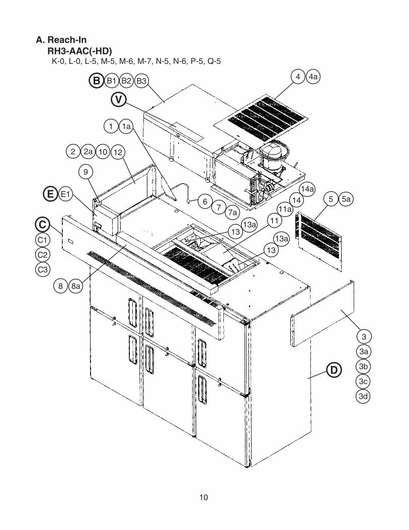
A. Reach-InRH3-AAC(-HD)
K-0, L-0, L-5, M-5, M-6, M-7, N-5, N-6, P-5, Q-5
B B1 B2 B3 4a4
5a5
7a7
6
1a1
2a2 10 12
E E1
CC1
C2
C3
8a8
9
3a
3
3b
3c
3d
D
V
11
11a14
14a
13
13a13
13a
11
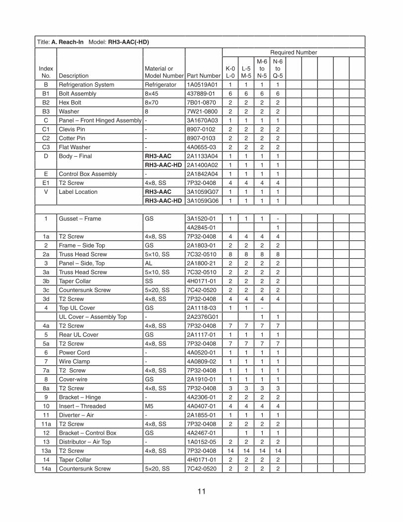
Title: A. Reach-In Model: RH3-AAC(-HD)
Index No. Description
Material or Model Number Part Number
Required Number
K-0 L-0
L-5M-5
M-6to
N-5
N-6to
Q-5
B Refrigeration System Refrigerator 1A0519A01 1 1 1 1
B1 Bolt Assembly 8×45 437889-01 6 6 6 6
B2 Hex Bolt 8×70 7B01-0870 2 2 2 2
B3 Washer 8 7W21-0800 2 2 2 2
C Panel – Front Hinged Assembly - 3A1670A03 1 1 1 1
C1 Clevis Pin - 8907-0102 2 2 2 2
C2 Cotter Pin - 8907-0103 2 2 2 2
C3 Flat Washer - 4A0655-03 2 2 2 2
D Body – Final RH3-AAC 2A1133A04 1 1 1 1
RH3-AAC-HD 2A1400A02 1 1 1 1
E Control Box Assembly - 2A1842A04 1 1 1 1
E1 T2 Screw 4×8, SS 7P32-0408 4 4 4 4
V Label Location RH3-AAC 3A1059G07 1 1 1 1
RH3-AAC-HD 3A1059G06 1 1 1 1
1 Gusset – Frame GS 3A1520-01 1 1 1 -
4A2845-01 1
1a T2 Screw 4×8, SS 7P32-0408 4 4 4 4
2 Frame – Side Top GS 2A1803-01 2 2 2 2
2a Truss Head Screw 5×10, SS 7C32-0510 8 8 8 8
3 Panel – Side, Top AL 2A1800-21 2 2 2 2
3a Truss Head Screw 5×10, SS 7C32-0510 2 2 2 2
3b Taper Collar SS 4H0171-01 2 2 2 2
3c Countersunk Screw 5×20, SS 7C42-0520 2 2 2 2
3d T2 Screw 4×8, SS 7P32-0408 4 4 4 4
4 Top UL Cover GS 2A1118-03 1 1 -
UL Cover – Assembly Top - 2A2376G01 1 1
4a T2 Screw 4×8, SS 7P32-0408 7 7 7 7
5 Rear UL Cover GS 2A1117-01 1 1 1 1
5a T2 Screw 4×8, SS 7P32-0408 7 7 7 7
6 Power Cord - 4A0520-01 1 1 1 1
7 Wire Clamp - 4A0809-02 1 1 1 1
7a T2 Screw 4×8, SS 7P32-0408 1 1 1 1
8 Cover-wire GS 2A1910-01 1 1 1 1
8a T2 Screw 4×8, SS 7P32-0408 3 3 3 3
9 Bracket – Hinge - 4A2306-01 2 2 2 2
10 Insert – Threaded M5 4A0407-01 4 4 4 4
11 Diverter – Air - 2A1855-01 1 1 1 1
11a T2 Screw 4×8, SS 7P32-0408 2 2 2 2
12 Bracket – Control Box GS 4A2467-01 1 1 1
13 Distributor – Air Top - 1A0152-05 2 2 2 2
13a T2 Screw 4×8, SS 7P32-0408 14 14 14 14
14 Taper Collar 4H0171-01 2 2 2 2
14a Countersunk Screw 5×20, SS 7C42-0520 2 2 2 2

12
B. Refrigeration SystemRH1-AAC(-HD)
K-0, K-1, L-0, L-5, M-5, M-6, M-7, N-5, N-6, P-5, P-6, P-7, Q-5
1a1 1b 1c
2 3 4 5 6a6
19 20 21 22
F F1
G
H H1
11 11a12
8
7
918
18a
1513 14 17 17a
16
10
23

13
Title: B. Refrigeration System Model: RH1-AAC(-HD)
Index No. Description
Material or Model Number Part Number
Required Number
K-0 K-1 L-0
L-5 to
N-5N-6 P-5
P-6 to
Q-5F Fan – Evap Assembly - 2A0980A01 1 1 1 1 1F1 Truss Head Screw 4×12, SS 7C32-0412 4 4 4 4 4G Evaporator Assembly - 2A1808A01 1 1 1 1 1H Condenser Assembly - 3A1087A02 1 1 1 -
3A2609A02 1 1
H1 T2 Screw 4×8, SS 7P32-0408 2 2 2 2 2
1 Cover – Evap Case (1 Sec) - 2A0428G01 1 1 1 -2A2726G01 1 1
1a Draw Latch 97-50-224-11 4A1710-01 4 4 4 4 41b Truss Head Screw 4×16, SS 7C32-0416 4 4 4 4 41c T2 Screw 4×8, SS 7P32-0408 8 8 8 8 82 Compressor 105G5724
NF7FX4A2133-01 1 1 1 1 1
3 Rubber Grommet - 4A1452-01 4 -Grommet 434403-01 4 4 4 4
4 Sleeve - 4A1451-01 4 -Spacer 434404-01 4 4 4 4
5 Washer - 4A1450-01 4 -Flat Washer 7W21-0800 4 4 4 4
6 Bolt - 4A1459-01 4 -7B01-0845 4 4 4 4
6a Split Lock Washer - 7L21-0800 4 4 -7 Pipe – Evap Drain PVC 4A0831-01 1 1 1 1 18 Filter – Cond - 3A0277-01 1 1 1 1 19 Drier SPORLAN
CW-052-S4A0924-01 1 1 1 1 1
10 Thermistor – Cabinet Thermistor is included w/ controller. (Assembly E)Thermistor is not replaceable as a standalone part.
- - - - -
11 Thermistor Bracket (A) ABS 433964-01 1 1 1 1 111a Truss Head Screw 4×16, SS 7C32-0416 2 2 2 2 212 Thermistor Bracket (B) ABS 433920-01 1 1 1 1 113 Fitting – Drain Overflow - 4A2182-01 1 1 1 1 114 Gasket – Cond. Coil 4A0455-03 1 1 1 1 115 Rubber Gasket 413854-03 1 1 1 1 116 Pan – Evap. Drain 2A0616-02 1 1 1 -
2A2760-01 1 117 Strap – Condensate Coil (3A0381A03) 3A0232-03 1 1 1 1 1
17a Truss Head Screw 5×12, SS 7C32-0512 2 2 2 1 118 Drier Bracket - 4A0806-01 1 1 1 1 118a T2 Screw 4×8, SS 7P32-0408 2 2 2 2 2
19 Start Capacitor 4A2134-01 1 1 1 1 120 Start Relay 4A2135-01 1 1 1 1 121 Cover – Compressor 4A2141-01 1 1 1 1 122 Cord Relief 4A2152-01 1 1 1 1 123 Pressure Switch 4A2516-01 1 1 1 1 1

14
B. Refrigeration SystemRH2-AAC(-HD)
K-0, L-5, M-5, M-6, M-7, N-5, N-6, P-5, P-6, P-7, Q-5
1a1 1b 1c
2 3 4 5 6
19 20 21 22
F F1
H H1
11 11a
12
8
7 9
18
18a
15 1314 17 17a
16
G G1
10
23

15
Title: B. Refrigeration System Model: RH2-AAC(-HD)
Index No. Description
Material or Model Number Part Number
Required Number
K-0
L-5to
P-5
P-6to
Q-5F Evaporator Shroud Assembly - 3A0263G01 1 1 1F1 Truss Head Screw 4×16 7C32-0416 2 2 2G Evaporator Assembly - 2A1297A03 1 1 1
G1 T2 Screw 4×8, SS 7P32-0408 2 2 2H Condenser Assembly - 3A1138A01 1 1 1
H1 T2 Screw 4×8, SS 7P32-0408 4 4 4
1 Cover – Evap Case - 2A0245G01 1 1 11a Draw Latch 97-50-224-11 4A1710-01 4 4 41b Truss Head Screw 4×16, SS 7C32-0416 4 4 41c T2 Screw 4×8, SS 7P32-0408 8 8 82 Compressor 105G5945
NF11FX4A2131-01 1 1 1
3 Rubber Grommet - 4A1452-01 4 -434403-01 4 4
4 Sleeve - 4A1451-01 4 -434404-01 4 4
5 Washer - 4A1450-01 4 -7W21-0800 4 4
6 Bolt - 4A1459-01 4 -7B01-0845 4 4
7 Pipe – Evap Drain PVC 3A0143-01 1 1 18 Filter – Condenser - 3A0277-02 1 1 19 Drier SPORLAN
CW-052-S4A0924-01 1 1 1
10 Thermistor – Cabinet Thermistor is included w/ controller. (Assembly E)Thermistor is not replaceable as a standalone part.
- - -
11 Thermistor Bracket (A) ABS 433964-01 1 1 111a Truss Head Screw 4×16, SS 7C32-0416 2 2 212 Thermistor Bracket (B) ABS 433920-01 1 1 113 Fitting – Drain Overflow 4A2182-01 1 1 1
14 Gasket – Cond. Coil 4A0455-01 1 1 115 Rubber Gasket 413854-03 1 1 1
16 Pan – Evaporator Drain 2A0200-02 1 1 1
17 Strap – Condensate Coil 3A0413-03 1 1 1
17a Truss Head Screw 5×10, SS 7C32-0510 1 1 118 Drier Bracket - 4A0806-01 1 1 118a T2 Screw - 7P32-0408 2 2 219 Start Capacitor 4A2134-02 1 1 120 Start Relay 4A2135-02 1 1 121 Cover – Compressor 4A2141-01 1 1 122 Cord Relief 4A2152-01 1 1 123 Pressure Switch 4A2516-01 1 1 1
16
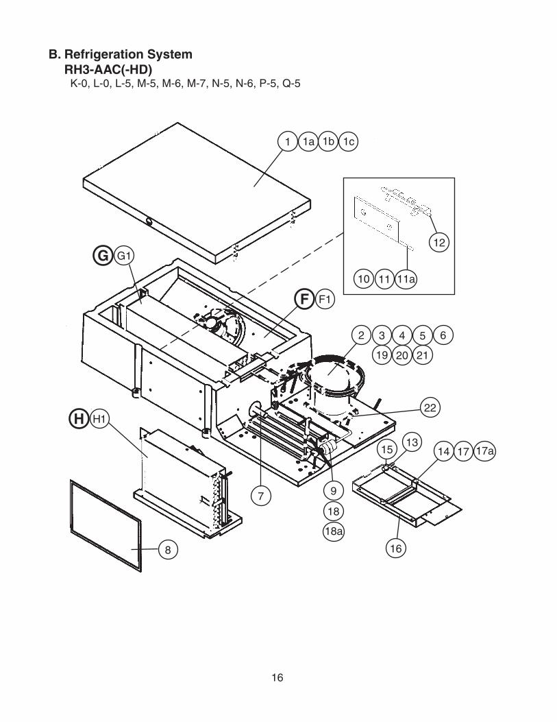
B. Refrigeration SystemRH3-AAC(-HD)
K-0, L-0, L-5, M-5, M-6, M-7, N-5, N-6, P-5, Q-5
1a1 1b 1c
2 3 4 5 6
19 20 21
F F1
H H1
8
7 9
18
18a
1513
14 17 17a
16
G G1
11 11a
12
10
22

17
Title: B. Regrigeration System Model: RH3-AAC(-HD)
Index No. Description
Material or Model Number Part Number
Required Number
K-0 to
P-5 Q-5
F Evap Shroud Assm - 3A1009G01 1 1
F1 Truss Head Screw 4×16, SS 7C32-0416 2 2
G Evaporator Assembly - 2A1160A02 1 1
G1 T2 Screw 4×8, SS 7P32-0408 2 2
H Condenser Assembly - 3A1010A02 1 1
H1 T2 Screw 4×8, SS 7P32-0408 4 4
1 Cover – Evap Case - 2A1086G01 1 1
1a Draw Latch 97-50-224-11 4A1710-01 4 4
1b Truss Head Screw 4×16, SS 7C32-0416 4 4
1c T2 Screw 4×8, SS 7P32-0408 8 8
2 Compressor - 3A1730-01 1 1
3 Grommet - 434403-01 4 4
4 Spacer - 434404-01 4 4
5 Flat Washer - 7W21-0800 4 4
6 Hex Bolt - 7B01-0845 4 4
7 Pipe – Evap Drain PVC 3A0143-01 1 1
8 Filter – Condenser - 3A0277-03 1 1
9 Drier SPORLAN CW-052-S
4A0924-01 1 1
10 Thermistor – Cabinet Thermistor is included w/ controller. (Assembly E)Thermistor is not replaceable as a standalone part.
- -
11 Thermistor Bracket (A) ABS 433964-01 1 1
11a Truss Head Screw 4×16, SS 7C32-0416 2 2
12 Thermistor Bracket (B) ABS 433920-01 1 1
13 Fitting – Drain Overflow 4A2182-01 1 1
14 Gasket – Cond. Coil 4A0455-01 1 1
15 Rubber Gasket 413854-03 1 1
16 Pan – Evaporator Drain 2A0200-02 1 1
17 Strap – Condensate Coil 3A0413-03 1 1
17a Truss Head Screw 5×10, SS 7C32-0510 1 1
18 Drier Bracket - 4A0806-01 1 1
18a T2 Screw 4×8, SS 7P32-0408 2 2
19 Protector Supplied w/ compressor
4A1875-01 1 1
20 Protector Holder 26126 Supplied w/ compressor
1 1
21 Protector Cover Group AKP1000 1 1
22 Pressure Switch 4A2516-01 1 1
18
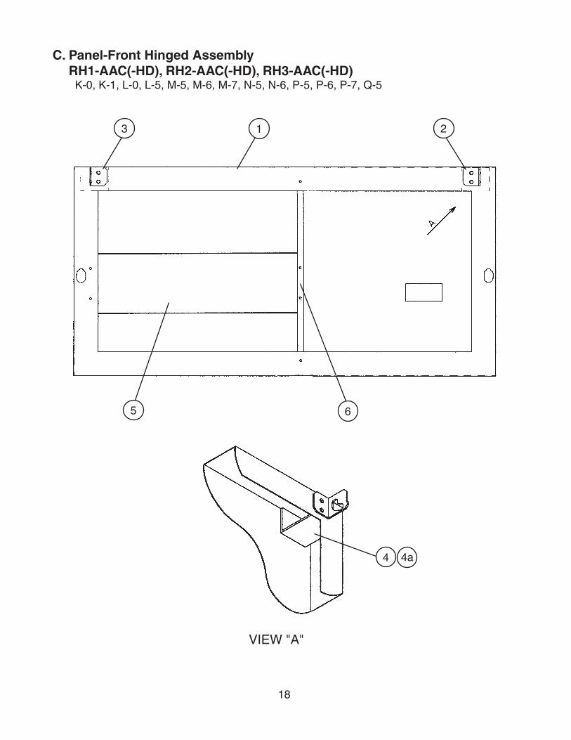
C. Panel-Front Hinged AssemblyRH1-AAC(-HD), RH2-AAC(-HD), RH3-AAC(-HD)
K-0, K-1, L-0, L-5, M-5, M-6, M-7, N-5, N-6, P-5, P-6, P-7, Q-5
VIEW "A"
3 1 2
5 6
4a4

19
Title: C. Panel-Front Hinged Assembly Model: RH1-AAC(-HD), RH2-AAC(-HD), RH3-AAC(-HD)
Index No. Description
Material or Model Number Part Number
Required Number
K-0 K-1
L-0to
Q-5
1 Panel – Front Hinged RH1-AAC(-HD)SS
2A1799-01 1 1
RH2-AAC(-HD)SS
2A1799-02 1 1
RH3-AAC(-HD)SS
2A1799-03 1 1
2 Hinge – Front Panel(L) GS 4A2153-01 1 1
3 Hinge – Front Panel(R) GS 4A2154-01 1 1
4 Channel – Hinge GS 4A2170-01 2 2
4a Truss Head Screw 5×8, SS 7C32-0508 4 4
5 Blind RH1-AAC(-HD) 3A1763-01 1RH2-AAC(-HD) 3A1763-02 1RH3-AAC(-HD) 3A1763-03 1 1
6 Support – Blind RH1-AAC(-HD)RH2-AAC(-HD)
4A2267-01 1
RH3-AAC(-HD) 1 1

20
D. Body-FinalRH1-AAC
K-0, K-1, L-0, L-5, M-5, M-6, M-7, N-5, N-6, P-5, P-6, P-7, Q-5
K
J
11
11a
10
3
2
5
4
1
9
8
6a6
7a7

21
Title: D. Body-Final Model: RH1-AAC
Index No. Description
Material or Model Number Part Number
Required Number
K-0
K-1to
Q-5
J Body – Prefinal - 1A0298A03 1 1
K Door – Right - 1A0318A03 1 1
1 Hinge – Stop Pin PS 4A2180-01 1 1
2 Hinge – Tension Screw PS 4A0446-01 1 1
3 Hinge – Bushing Cover SS 4A0445-01 1 1
4 Hinge – Lock Washer PS 4A0553-01 1 1
5 Hinge – Pivot Pin (Top) PS 4A2179-01 1 1
6 Bracket – Door Hinge (LR) PS 3A1626-01 1 1
6a Countersunk Screw 5×20, SS 7C42-0520 3 3
7 Bracket – Door Hinge (UR) PS 3A1580-01 1 1
7a Countersunk Screw 5×20, SS 7C42-0520 3 3
8 Hinge – Stop Plate (R) PS 4A0441-01 1 1
9 Screw – Stop Plate PS 4A0483-01 1 1
10 Cover – Corner ABS 3A0221-01 4 -
- 3A1751-01 4
11 Plate – Strike (Side) SS 4A0470-01 1 1
11a T2 Screw 4×8, SS 7P32-0408 2 2

22
D. Body-FinalRH1-AAC-HD
K-0, K-1, L-0, L-5, M-5, N-6, P-5, P-6, Q-5
M
10 10a
9a9
N
R
J
5
3
7
6
1 2
6
4
8a8
11
12
11
12
13

23
Title: D. Body-Final Model: RH1-AAC-HD
Index No. Description
Material or Model Number Part Number
Required Number
K-0
K-1to
Q-5
J Body – Prefinal - 1A0354A02 1 1
M Door – Half (UR) - 1A0326A03 1 1
N Door – Half (LR) - 1A0324A03 1 1
R Mullion – Horizontal - 2A1323A02 1 1
1 Hinge – Stop Pin PS 4A2180-01 1 1
2 Stop Pin PS 4A1734-01 1 1
3 Hinge – Tension Screw SS 4A0446-01 2 2
4 Pivot Pin PS 4A1735-01 1 1
5 Hinge – Bushing Cover PS 4A0445-01 2 2
6 Hinge – Lock Washer PS 4A0553-01 2 2
7 Hinge – Pivot Pin (Top) PS 4A2179-01 1 1
8 Bracket – Door Hinge (LR) PS 3A1626-01 1 1
8a Countersunk Screw 5×20, SS 7C42-0520 3 3
9 Bracket – Door Hinge (UR) PS 3A1580-01 1 1
9a Countersunk Screw 5×20, SS 7C42-0520 3 3
10 Bracket – Door Hinge (UL) PS 3A1581-01 1 1
10a Countersunk Screw 5×20, SS 7C42-0520 3 3
11 Hinge – Stop Plate (R) PS 4A0441-01 2 2
12 Screw – Stop Plate PS 4A0483-01 2 2
13 Cover – Corner ABS 3A0221-01 4 -
- 3A1751-01 4

24
D. Body-FinalRH2-AAC
K-0, L-5, M-5, M-6, M-7, N-6, P-5, P-6, P-7, Q-5
K
J
12
6a6
L
S
10
12
7a78a89a9
3
2
4
5
1
45
111
13

25
Title: D. Body-Final Model: RH2-AAC
Index No. Description
Material or Model Number Part Number
Required Number
K-0
L-5to
Q-5
J Body – Prefinal - 2A1207A04 1 1
K Door – Right - 1A0318A03 1 1
L Door – Left - 1A0318A04 1 1
S Mullion – Vertical - 2A1289A03 1 1
1 Hinge – Stop Pin PS 4A2180-01 2 2
2 Hinge – Tension Screw PS 4A0446-01 2 2
3 Hinge – Bushing Cover SS 4A0445-01 2 2
4 Hinge – Lock Washer PS 4A0553-01 2 2
5 Hinge – Pivot Pin(Top) PS 4A2179-01 2 2
6 Bracket – Door Hinge(LR) PS 3A1626-01 1 1
6a Countersunk Screw 5×20, SS 7C42-0520 3 3
7 Bracket – Door Hinge(LL) PS 3A1627-01 1 1
7a Countersunk Screw 5×20, SS 7C42-0520 3 3
8 Bracket – Door Hinge(UR) PS 3A1580-01 1 1
8a Countersunk Screw 5×20, SS 7C42-0520 3 3
9 Bracket – Door Hinge(UL) PS 3A1581-01 1 1
9a Countersunk Screw 5×20, SS 7C42-0520 3 3
10 Hinge – Stop Plate(R) PS 4A0441-01 1 1
11 Hinge – Stop Plate(L) PS 4A0441-02 1 1
12 Screw – Stop Plate PS 4A0483-01 2 2
13 Cover – Corner ABS 3A0221-01 8 -
- 3A1751-01 8
26
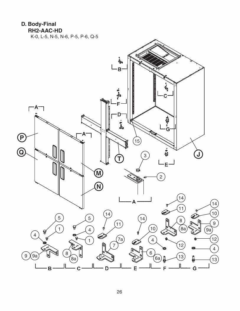
D. Body-FinalRH2-AAC-HD
K-0, L-5, N-5, N-6, P-5, P-6, Q-5
P
Q
M
N
JT
9a98a
8
7a7
6a6
8a
8
9a9
3
2
4
5
1
5
4
1 4
4
14
1114
10
14
11
12
1313
12
10
14
15

27
Title: D. Body-Final Model: RH2-AAC-HD
Index No. Description
Material or Model Number Part Number
Required Number
K-0
L-5to
Q-5
J Body – Prefinal - 2A1347A02 1 1
M Door – Half (UR) - 1A0326A03 1 1
N Door – Half (LR) - 1A0324A03 1 1
P Door – Half (UL) - 1A0324A04 1 1
Q Door – Half (LL) - 1A0326A04 1 1
T Mullion – Cross - 2A1350A02 1 1
1 Hinge – Stop Pin PS 4A2180-01 2 2
2 Hinge – Tension Screw PS 4A0446-01 4 4
3 Hinge – Bushing Cover SS 4A0445-01 4 4
4 Hinge – Lock Washer PS 4A0553-01 4 4
5 Hinge – Pivot Pin (Top) PS 4A2179-01 2 2
6 Bracket – Door Hinge (LR) PS 3A1626-01 1 1
6a Countersunk Screw 5×20, SS 7C42-0520 3 3
7 Bracket – Door Hinge (LL) PS 3A1627-01 1 1
7a Countersunk Screw 5×20, SS 7C42-0520 3 3
8 Bracket – Door Hinge (UR) PS 3A1580-01 2 2
8a Countersunk Screw 5×20, SS 7C42-0520 6 6
9 Bracket – Door Hinge (UL) PS 3A1581-01 2 2
9a Countersunk Screw 5×20, SS 7C42-0520 6 6
10 Hinge – Stop Plate (R) PS 4A0441-01 2 2
11 Hinge – Stop Plate (L) PS 4A0441-02 2 2
12 Stop Pin PS 4A1734-01 2 2
13 Pivot Pin PS 4A1735-01 2 2
14 Screw – Stop Plate PS 4A0483-01 4 4
15 Cover – Corner ABS 3A0221-01 16 -
- 3A1751-01 16

28
D. Body-FinalRH3-AAC
K-0, L-0, L-5, M-5, M-6, M-7, N-5, N-6, P-5, Q-5
LS
K
3
2
5
41
45
1
J
9a9
8a
8 7a7
6a
6
11
1212
10
13

29
Title: D. Body-Final Model: RH3-AAC
Index No. Description
Material or Model Number Part Number
Required Number
K-0 to
Q-5
J Body – Prefinal - 2A1132A04 1
K Door – Right - 1A0318A03 2
L Door – Left - 1A0318A04 1
S Mullion – Vertical - 2A1289A03 2
1 Hinge – Stop Pin PS 4A2180-01 3
2 Hinge – Tension Screw PS 4A0446-01 3
3 Hinge – Bushing Cover SS 4A0445-01 3
4 Hinge – Lock Washer PS 4A0553-01 3
5 Hinge – Pivot Pin (Top) PS 4A2179-01 3
6 Bracket – Door Hinge (LR) PS 3A1626-01 2
6a Countersunk Screw 5×20, SS 7C42-0520 6
7 Bracket – Door Hinge (LL) PS 3A1627-01 1
7a Countersunk Screw 5×20, SS 7C42-0520 3
8 Bracket – Door Hinge (UR) PS 3A1580-01 2
8a Countersunk Screw 5×20, SS 7C42-0520 6
9 Bracket – Door Hinge (UL) PS 3A1581-01 1
9a Countersunk Screw 5×20, SS 7C42-0520 3
10 Hinge – Stop Plate (R) PS 4A0441-01 2
11 Hinge – Stop Plate (L) PS 4A0441-02 1
12 Screw – Stop Plate PS 4A0483-01 3
13 Cover – Corner ABS 3A1751-01 12

30
D. Body-FinalRH3-AAC-HD
K-0, N-6, Q-5
P
M
N
Q N
MT
U
J
9a
9
8a8
7a
7
6a
6
8a
8
9a
9
4
5
1
5
4
1 4
4
3
2
14
11
1410
11
14
12
13 13
12
1014
15

31
Title: D. Body-Final Model: RH3-AAC-HD
Index No. Description
Material or Model Number Part Number
Required Number
K-0 to
Q-5
J Body – Prefinal - 2A1399A02 1
M Door – Half (UR) - 1A0326A03 2
N Door – Half (LR) - 1A0324A03 2
P Door – Half (UL) - 1A0324A04 1
Q Door – Half (LL) - 1A0326A04 1
T Mullion – Cross - 2A1350A02 1
U Mullion – Tee (L) 2A1385A02 1
1 Hinge – Stop Pin PS 4A2180-01 3
2 Hinge – Tension Screw PS 4A0446-01 6
3 Hinge – Bushing Cover SS 4A0445-01 6
4 Hinge – Lock Washer PS 4A0553-01 6
5 Hinge – Pivot Pin (Top) PS 4A2179-01 3
6 Bracket – Door Hinge (LR) PS 3A1626-01 2
6a Countersunk Screw 5×20, SS 7C42-0520 6
7 Bracket – Door Hinge (LL) PS 3A1627-01 1
7a Countersunk Screw 5×20, SS 7C42-0520 3
8 Bracket – Door Hinge (UR) PS 3A1580-01 3
8a Countersunk Screw 5×20, SS 7C42-0520 9
9 Bracket – Door Hinge (UL) PS 3A1581-01 3
9a Countersunk Screw 5×20, SS 7C42-0520 9
10 Hinge – Stop Plate (R) PS 4A0441-01 4
11 Hinge – Stop Plate (L) PS 4A0441-02 2
12 Stop Pin PS 4A1734-01 3
13 Pivot Pin PS 4A1735-01 3
14 Screw – Stop Plate PS 4A0483-01 6
15 Cover – Corner ABS 3A1751-01 24

32
E. Control Box AssemblyRH1-AAC(-HD), RH2-AAC(-HD), RH3-AAC(-HD)
K-0, K-1, L-0, L-5, M-5, M-6, M-7, N-5, N-6, P-5, P-6, P-7, Q-5
Title: E. Control Box Assembly Model: RH1-AAC(-HD), RH2-AAC(-HD), RH3-AAC(-HD)
Index No. Description
Material or Model Number Part Number
Required Number
K-0 K-1
L-0L-5
M-5to
N-5
N-6 to
P-5
P-6to
Q-5
1 Base – Control Box GS 2A1887-01 1 1 1 1 1
2 Cover – Control Box GS 2A1833-01 1 1 1 1 1
3 Board – Control Display Use latest for all aux. codes
4A2203-01 1 1 1 1 -
Controller 3A3372-01 1
4 Switch – Rocker 1801.110 4A0418-01 1 1 1 1 1
5 Switch – Toggle 780K21 4A0424-01 1 1 1 1 1
6 Relay – Compressor HE1aN-AC120V
4A1307-01 1 1 1 1 1
7 Tapping Screw 3×8 431415-01 1 1 1 1 1
8 Transformer BE110805GAA 4A2202-01 1 1 1 1 1
9 Tapping Screw 3×8 431415-01 2 2 2 2 2
1
6 7
2
3
4
5 8 9
20 21
14 15
12 13
16 17
22
18 19
25 26
10 11
27 28
24
23

33
Title: E. Control Box Assembly Model: RH1-AAC(-HD), RH2-AAC(-HD), RH3-AAC(-HD)
Index No. Description
Material or Model Number Part Number
Required Number
K-0 K-1
L-0L-5
M-5to
N-5
N-6 to
P-5
P-6to
Q-5
10 Terminal Block RH1-AAC(-HD) RH2-AAC(-HD) ESB1-6-8
4A1540-01 1 1 -
RH1-AAC(-HD) RH2-AAC(-HD)ESB2-323-424
4A2619-01 1 1 1
RH3-AAC(-HD) ESB1-6-8
4A1540-01 1 1 1 -
RH3-AAC(-HD) ESB2-323-424
4A2619-01 1 1
11 Tapping Screw 3×8 431415-01 1 1 1 1 1
12 Plug Housing 3/12/35 4A0425-01 1 1 1 1 1
13 Receptacle Housing 03-12-1036 4A0426-01 1 1 1 1 1
14 Plug Housing(6 Pin) 3191-06P 412832-03 1 1 1 1 1
15 Receptacle Housing(6 Pin) 3191-06R1 412831-03 1 1 1 1 1
16 Plug Housing(6 Pin) 3191-06P 412832-12 1 1 1 1 1
17 Receptacle Housing(6 Pin) 3191-06R1 412831-12 1 1 1 1 1
18 Insert – Threaded M5 4A0407-01 1 1 1 1 1
19 Truss Head Screw 5×10 7C32-0510 1 1 1 1 1
20 Relay – Door Switch JA1b-TM-AC12V 4A2268-01 1 1 1 1 1
21 Tapping Screw 3×8 431415-01 2 2 2 2 2
22 Bushing SB-625-8 420470-01 1 1 1 1 1
23 Bushing RH1-AAC(-HD) OnlySB-1500-21
420470-06 1 -
24 Capacitor – Starting RH3-AAC(-HD) Only
3A0076-14 1 1 1 1 1
25 Relay – Start RH3-AAC(-HD) Only
4A1709-02 1 1 1 1 1
26 Truss Head Screw RH3-AAC(-HD) Only4×8, SS
7C32-0408 1 1 1 1 1
27 Strap RH3-AAC(-HD) OnlyGS
434580-05 1 1 -
434580-03 1 1 1
28 Tapping Screw RH3-AAC(-HD) Only3×8
431415-01 1 1 1 1 1

34
1 1a
2c
5
2 2a 2b
4
3 3a 3b 3c
1 1a
2c
5
2 2a 2b
4
3 3a 3b 3c
HS2 HS2a HS2b
HS1 HS1a HS1b
HS3 HS3a HS3b HS3cHS4
See next page for information about non-interchangeable part change.
HS-3541
HS5
F. Fan-Evaporator AssemblyRH1-AAC(-HD)
K-0, K-1, L-0, L-5
F. Fan-Evaporator AssemblyRH1-AAC(-HD)
M-5, M-6, M-7, N-5, N-6, P-5, P-6, P-7, Q-5
35
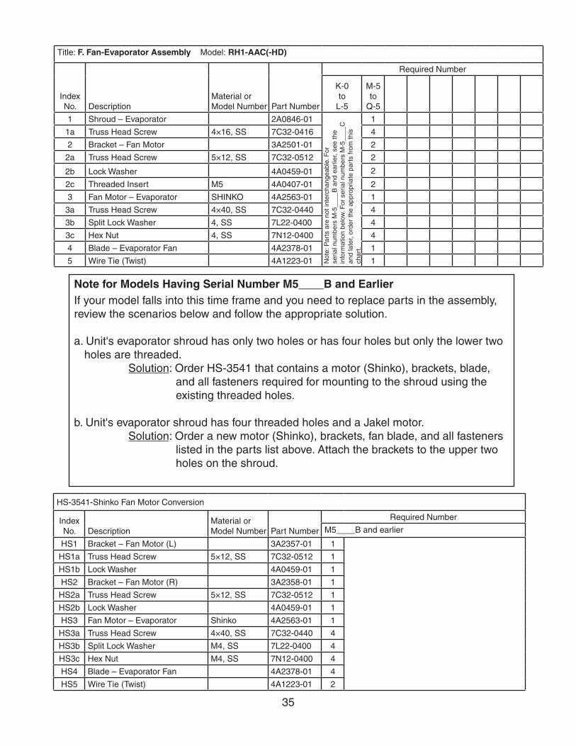
Title: F. Fan-Evaporator Assembly Model: RH1-AAC(-HD)
Index No. Description
Material or Model Number Part Number
Required Number
K-0to
L-5
M-5to
Q-5
1 Shroud – Evaporator 2A0846-01
Not
e: P
arts
are
not
inte
rcha
ngea
ble.
For
se
rial n
umbe
rs M
-5__
__B
and
ear
lier,
see
the
info
rmat
ion
belo
w. F
or s
eria
l num
bers
M-5
____
C
and
late
r, or
der
the
appr
opria
te p
arts
from
this
ch
art.
1
1a Truss Head Screw 4×16, SS 7C32-0416 4
2 Bracket – Fan Motor 3A2501-01 2
2a Truss Head Screw 5×12, SS 7C32-0512 2
2b Lock Washer 4A0459-01 2
2c Threaded Insert M5 4A0407-01 2
3 Fan Motor – Evaporator SHINKO 4A2563-01 1
3a Truss Head Screw 4×40, SS 7C32-0440 4
3b Split Lock Washer 4, SS 7L22-0400 4
3c Hex Nut 4, SS 7N12-0400 4
4 Blade – Evaporator Fan 4A2378-01 1
5 Wire Tie (Twist) 4A1223-01 1
Note for Models Having Serial Number M5____B and EarlierIf your model falls into this time frame and you need to replace parts in the assembly, review the scenarios below and follow the appropriate solution.
a. Unit's evaporator shroud has only two holes or has four holes but only the lower two holes are threaded.
Solution: Order HS-3541 that contains a motor (Shinko), brackets, blade, and all fasteners required for mounting to the shroud using the existing threaded holes.
b. Unit's evaporator shroud has four threaded holes and a Jakel motor.Solution: Order a new motor (Shinko), brackets, fan blade, and all fasteners
listed in the parts list above. Attach the brackets to the upper two holes on the shroud.
HS-3541-Shinko Fan Motor Conversion
Index No. Description
Material or Model Number Part Number
Required Number
M5____B and earlier
HS1 Bracket – Fan Motor (L) 3A2357-01 1
HS1a Truss Head Screw 5×12, SS 7C32-0512 1
HS1b Lock Washer 4A0459-01 1
HS2 Bracket – Fan Motor (R) 3A2358-01 1
HS2a Truss Head Screw 5×12, SS 7C32-0512 1
HS2b Lock Washer 4A0459-01 1
HS3 Fan Motor – Evaporator Shinko 4A2563-01 1
HS3a Truss Head Screw 4×40, SS 7C32-0440 4
HS3b Split Lock Washer M4, SS 7L22-0400 4
HS3c Hex Nut M4, SS 7N12-0400 4
HS4 Blade – Evaporator Fan 4A2378-01 4
HS5 Wire Tie (Twist) 4A1223-01 2
36
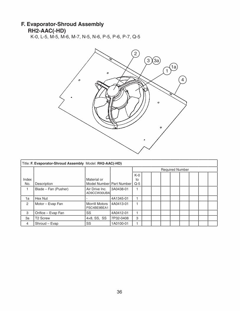
F. Evaporator-Shroud AssemblyRH2-AAC(-HD)
K-0, L-5, M-5, M-6, M-7, N-5, N-6, P-5, P-6, P-7, Q-5
2
3 3a
1
4
1a
Title: F. Evaporator-Shroud Assembly Model: RH2-AAC(-HD)
Index No. Description
Material or Model Number Part Number
Required Number
K-0 to
Q-5
1 Blade – Fan (Pusher) Air Drive Inc.AD9CCW30UBA
3A0438-01 1
1a Hex Nut - 4A1345-01 1
2 Motor – Evap Fan Morrill MotorsPSC4BE9BEA1
4A0413-01 1
3 Orifice – Evap Fan SS 4A0412-01 1
3a T2 Screw 4×8, SS, SS 7P32-0408 3
4 Shroud – Evap SS 1A0100-01 1

37
F. Evaporator-Shroud AssemblyRH3-AAC(-HD)
K-0, L-0, L-5, M-5, M-6, M-7, N-5, N-6, P-5, Q-5
Title: F. Evaporator-Shroud Assembly Model: RH3-AAC(-HD)
Index No.
Description Material or Model Number
Part Number Required Number
K-0 to
N-6
1 Shroud – Evaporator - 1A0248-01 1
2 Orifice – Evaporator Fan - 4A0412-01 1
2a T2 Screw 4×8, SS 7P32-0408 3
3 Motor – Evaporator Fan 4A0413-01 1
4 Blade – Fan (Pusher) - 3A0438-01 1
4a Hex Nut - 4A1345-01 1
1
2a2
3
4a
4

38
G. Evaporator AssemblyRH1-AAC(-HD)
K-0, K-1, L-0, L-5, M-5, M-6, M-7, N-5, N-6, P-5, P-6, P-7, Q-5
Title: G. Evaporator Assembly Model: RH1-AAC(-HD)
Index No. Description
Material or Model Number Part Number
Required Number
K-0 to
P-7 Q-5
1 Evaporator Heatcraft 03EZ0603K-8×19
2A1262-01 1 1
2 Bracket – Evaporator SS 4A2542-01 2 2
2a T2 Screw 4×8, SS 7P32-0408 4 4
3 Thermistor – Defrost Thermistor is included w/ controller. (Assembly E)Thermistor is not replaceable as a standalone part.
- -
Clip – Thermistor 4A3248G01 1 1
4 Copper Tube CU 4A0554-02 1 1
2a2
2a2
1
4
3

39
G. Evaporator AssemblyRH2-AAC(-HD)
K-0, L-5, M-5, M-6, M-7, N-5, N-6, P-5, P-6, P-7, Q-5
Title: G. Evaporator Assembly Model: RH2-AAC(-HD)
Index No. Description
Material or Model Number Part Number
Required Number
K-0 to
P-7 Q-5
1 Evaporator Heatcraft 602899
2A1382-01 1 1
2 Bracket – Evap Shroud (R) SS 4A0545-01 1 1
2a T2 Screw 4×8, SS 7P32-0408 2 2
3 Bracket – Evap Shroud (L) SS 4A0548-01 1 1
3a T2 Screw 4×8, SS 7P32-0408 2 2
4 Thermistor – Defrost Thermistor is included w/ controller. (Assembly E)Thermistor is not replaceable as a standalone part.
- -
Clip – Thermistor 4A3248G01 1 1
5 Copper – Tube CU 4A0554-04 1 1
2a2
3a3
1
4
5

40
G. Evaporator AssemblyRH3-AAC(-HD)
K-0, L-0, L-5, M-5, M-6, M-7, N-5, N-6, P-5, Q-5
Title: G. Evaporator Assembly Model: RH3-AAC(-HD)
Index No. Description
Material or Model Number Part Number
Required Number
K-0 to
P-5 Q-5
1 Evaporator - 2A1159-01 1 1
2 Bracket – Evap Shroud (R) SS 4A0545-01 1 1
2a T2 Screw 4×8, SS 7P32-0408 2 2
3 Bracket – Evap Shroud (L) SS 4A0548-01 1 1
3a T2 Screw 4×8, SS 7P32-0408 2 2
4 Thermistor – Defrost Thermistor is included w/ controller. (Assembly E)Thermistor is not replaceable as a standalone part.
- -
Clip – Thermistor 4A3248G01 1 1
5 Copper Tube CU 4A0554-05 1 1
2a2
3a3
1
5
4

41
H. Condenser AssemblyRH1-AAC(-HD)
K-0, K-1, L-0, L-5, M-5, M-6, M-7, N-5, N-6, P-5, P-6, P-7, Q-5
9
3
2
5 6
4
7a7
8a8
1a1
3a

42
Title: H. Condenser Assembly Model: RH1-AAC(-HD)
Index No. Description
Material or Model Number Part Number
Required Number
K-0 to
N-5
N-6to
Q-5
1 Shroud – Condenser GS 2A1685-01 1 -
2A2722-01 1
1a T2 Screw 4×8, SS 7P32-0408 2 2
2 Base – Condenser GS 2A1027G01 1 -
2A2724G01 1
3 Condenser Heatcraft 2CZ1002N-12×9
2A0623-01 1 1
3a T2 Screw 4×8, SS 7P32-0408 4 4
4 Motor-9W - 4A0408-01 1 1
5 Blade – Cond Fan AIR DRIVE AD9CW30UBA
3A0436-01 1 1
6 Hex Nut PS 4A1345-01 1 1
7 Bracket – Condenser Fan GS 3A1564-01 1 1
7a Truss Head Screw 5×12 7C32-0512 4 4
8 Retainer – Filter GS 4A0790-01 1 1
8a T2 Screw 4×8, SS 7P32-0408 2 2
9 Insert – Threaded - 4A0407-01 5 5

43
H. Condenser AssemblyRH2-AAC(-HD)
K-0, L-5, M-5, M-6, M-7, N-5, N-6, P-5, P-6, P-7, Q-5
8
4 5
9a9
2a2
3
1
7
6a6

44
Title: H. Condenser Assembly Model: RH2-AAC(-HD)
Index No. Description
Material or Model Number Part Number
Required Number
K-0 to
Q-5
1 Condenser Heatcraft3CZ1002C-12×15
2A0261-01 1
2 Shroud – Condenser GS 2A1686-01 1
2a T2 Screw 4×8, SS 7P32-0408 8
3 Motor – Cond Fan SPGE9HBE1 4A0408-01 1
4 Blade – Fan Ref Air DriveAD9CW30UBA38
3A0436-01 1
5 Hex Nut ¼”-20 Zinc Plated
4A1345-01 1
6 Bracket – Cond Fan GS 3A1564-01 1
6a Truss Head Screw 5×12 7C32-0512 4
7 Base – Condenser GS 2A1217-01 1
8 Insert – Threaded - 4A0407-01 5
9 Retainer – Filter - 4A2138-01 1
9a T2 Screw 4×8, SS 7P32-0408 2

45
H. Condenser AssemblyRH3-AAC(-HD)
K-0, L-0, L-5, M-5, M-6, M-7, N-5, N-6, P-5, Q-5
8
4 5
9a9
2a2
3
1
7
6a6

46
Title: H. Condenser Assembly Model: RH3-AAC(-HD)
Index No. Description
Material or Model Number Part Number
Required Number
K-0 to
Q-5
1 Condenser - 2A1166-01 1
2 Shroud – Condenser GS 2A1715-01 1
2a T2 Screw 4×6, SS 7P32-0406 8
3 Motor – 16W SPGE9HBE1 4A0815-01 1
4 Blade – Fan (Puller) - 3A0608-01 1
5 Hex Nut 1/4”-20 ZINC PLATED
4A1345-01 1
6 Bracket – Cond Fan GS 3A1564-01 1
6a Truss Head Screw 5×12, SS 7C32-0512 4
7 Base – Condenser GS 2A1168-01 1
8 Insert – Threaded - 4A0407-01 5
9 Retainer – Filter - 4A2138-01 1
9a T2 Screw 4×8, SS 7P32-0408 2

47
J. Body-PrefinalRH1-AAC(-HD)
K-0, K-1, L-0, L-5, M-5, M-6, M-7, N-5, N-6, P-5, P-6, P-7, Q-5
6
7
1
M-6 and earlier for RH1-AAC
L-5 and earlier for RH1-AAC-HD
The santoprene light socket was changed to a porcelain lampholder at M-7 for FH1-AAC and at M-5 for FH2-AAC-HD. This change is non-interchangeable. If the light socket is not operating on a unit with a santoprene light socket, Hoshizaki recommends replacement with HS-3554.
Note:
Parts 4, 5 and 5a are not included in HS-3554; they are shown for reference only.
HS1
4
5a5
HS2
HS1a
HS2a
5a
5
2a2
3a3
8
M-7 and later for RH1-AAC
M-5 and later for RH1-AAC-HD
4
9
10

48
Title: J. Body-Prefinal Model: RH1-AAC(-HD)
Index No. Description
Material or Model Number Part Number
Required Number
K-0
K-1to
L-5M-5M-6
M-7to
N-7
1 Cabinet Prefoam (1 Sec) - 1A0173G03 1 1 1 1
2 Distributor – Air Top Assm ABS 2A0438G01 1 1 1 1
2a T2 Screw 4×8, SS, SS 7P32-0408 7 7 7 7
3 Pilaster AL 3A0145-21 4 4 4 4
3a Truss Head Screw 5×10, SS 7C32-0510 12 12 12 12
4 Bulb – Light GE, 40A15 4A0437-01 1 1 -
4A2420-01 1 1
5 Shield – Light STANDARD KEIL, 2778-1010-3000
4A0465-01 1 1 1 1
5a Cheese Head Screw 5×12, SS 7C52-0512 2 2 2 2
5b Washer RH1-AAC8, SS
7W22-0800 2 2 2 -
RH1-AAC-HD8, SS
2 2 -
6 Switch – Door RH1-AACNYLON
3A1386-01 1 -
3A1826-01 1 1 1
RH1-AAC-HDNYLON
3A1386-01 2 -
3A1826-01 2 2 2
7 Vinyl Hose L=1700 7730I3812 1 1 1 1
8 Bushing OCB-875 428394-04 2 2 2 2
9 Threaded Insert (Wide) RH1-AAC 4A0839-01 2
RH1-AAC-HD 2 2
10 Lampholder RH1-AAC 4A2862-01 Non-interchangeable part change. If light socket is not operating for these codes, Hoshizaki recommends replacement with HS-3554 (below).
1
RH1-AAC-HD 1 1
HS-3554-Lampholder Conversion Kit
Index No. Description
Material or Model Number Part Number
Required Number
M-6 and earlier for RH1-AACL-5 and earlier for RH1-AAC-HD
HS1 Plate – Lampholder Mount SS 4A2880-01 1
HS1a Cheese Head Screw SS 7C52-0512 2
HS2 Lampholder 4A2862-01 1
HS2a Terminal – Flag DNFR18-250FIBK
8101-18FJ 2
49
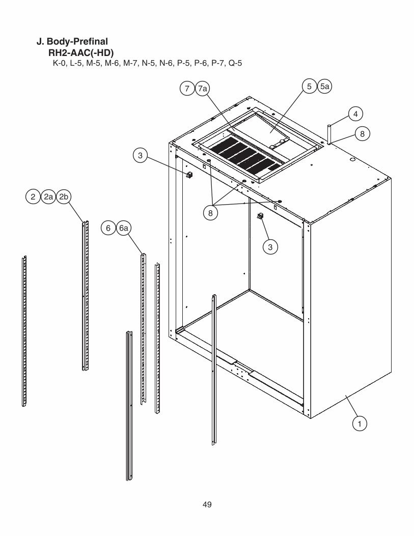
J. Body-PrefinalRH2-AAC(-HD)
K-0, L-5, M-5, M-6, M-7, N-5, N-6, P-5, P-6, P-7, Q-5
1
3
3
8
2a2 2b
6a6
7a7 5a5
4
8

50
Title: J. Body-Prefinal Model: RH2-AAC(-HD)
Index No. Description
Material or Model Number Part Number
Required Number
K-0
L-5to
P-6P-7Q-5
1 Cabinet – Prefoam RH2-AAC 2A0706G04 1 1 1
RH2-AAC-HD 2A1346G02 1 1 1
2 Pilaster AL 3A0145-21 4 4 4
2a Truss Head Screw 5×10, SS 7C32-0510 12 12 12
2b Threaded Insert M5 4A0407-01 12 12 12
3 Switch – Door RH2-AACNYLON
3A1386-01 2 -
3A1826-01 2 2
RH2-AAC-HDNYLON
3A1386-01 4 -
3A1826-01 4 4
4 Vinyl Hose L=1700 7730I3812 1 1 1
5 Baffle – Air - 2A0625-01 1 1 1
5a Truss Head Screw 5×10, SS 7C32-0510 2 2 2
6 Pilaster – Mullion AL 2A0205-21 2 2 -
2A3246-21 2
6a Truss Head Screw 5×10, SS 7C32-0510 6 6 6
7 Divider – Air - 2A0199-21 1 1 1
7a T2 Screw 4×8, SS 7P32-0408 4 4 4
8 Bushing OCB-875 428394-04 4 4 4

51
J. Body-PrefinalRH3-AAC(-HD)
K-0, L-0, L-5, M-5, M-6, M-7, N-5, N-6, P-5, Q-5
1
3
2a2 2b6a6
7
5a5
4
7

52
Title: J. Body-Prefinal Model: RH3-AAC(-HD)
Index No. Description
Material or Model Number Part Number
Required Number
K-0 to
P-5 Q-5
1 Cabinet – Prefoam RH3-AAC 2A1018G03 1 1
RH3-AAC-HD 2A1398G02 1 1
2 Pilaster AL 3A0145-21 4 4
2a Truss Head Screw 5×10, SS, SS 7C32-0510 12 12
2b Threaded Inserts M5 4A0407-01 12 12
3 Switch – Door RH3-AACNYLON
3A1826-01 3 3
RH3-AAC-HDNYLON
6 6
4 Vinyl Hose L=1700 7730I3812 1 1
5 Divider – Air - 2A1101-21 1 1
5a T2 Screw 4×8, SS, SS 7P32-0408 4 4
6 Pilaster – Mullion AL 2A0205-21 4 -
2A3246-21 4
6a Truss Head Screw 5×10, SS 7C32-0510 12 12
7 Bushing OCB-875 428394-04 6 6

53
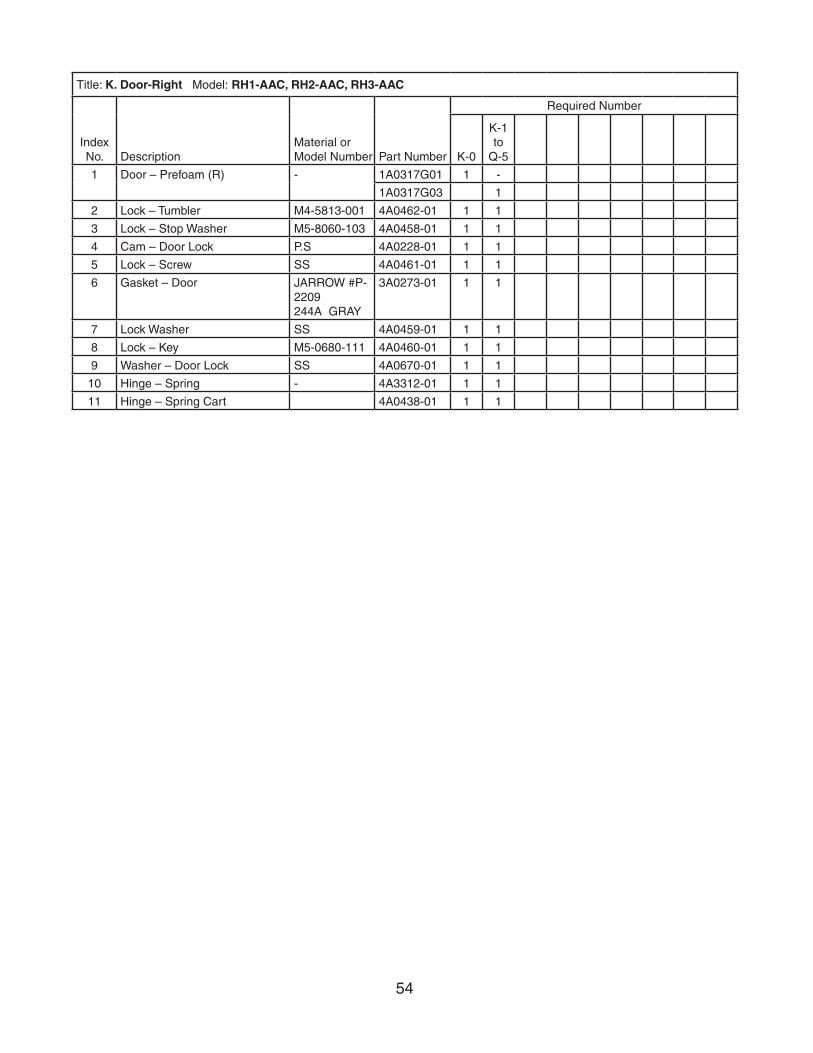
K. Door-RightRH1-AAC, RH2-AAC, RH3-AAC
K-0, K-1, L-0, L-5, M-5, M-6, M-7, N-5, N-6, P-5, P-6, P-7, Q-5
5
74
39
28
16
1011
54
Title: K. Door-Right Model: RH1-AAC, RH2-AAC, RH3-AAC
Index No. Description
Material or Model Number Part Number
Required Number
K-0
K-1to
Q-5
1 Door – Prefoam (R) - 1A0317G01 1 -
1A0317G03 1
2 Lock – Tumbler M4-5813-001 4A0462-01 1 1
3 Lock – Stop Washer M5-8060-103 4A0458-01 1 1
4 Cam – Door Lock P.S 4A0228-01 1 1
5 Lock – Screw SS 4A0461-01 1 1
6 Gasket – Door JARROW #P-2209244A GRAY
3A0273-01 1 1
7 Lock Washer SS 4A0459-01 1 1
8 Lock – Key M5-0680-111 4A0460-01 1 1
9 Washer – Door Lock SS 4A0670-01 1 1
10 Hinge – Spring - 4A3312-01 1 1
11 Hinge – Spring Cart 4A0438-01 1 1
55
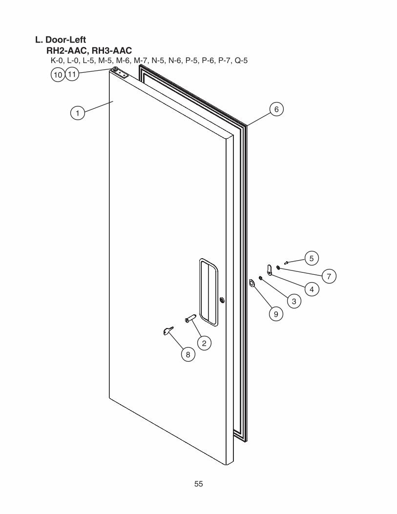
L. Door-LeftRH2-AAC, RH3-AAC
K-0, L-0, L-5, M-5, M-6, M-7, N-5, N-6, P-5, P-6, P-7, Q-5
5
7
4
3
9
2
8
1 6
10 11

56
Title: L. Door-Left Model: RH2-AAC, RH3-AAC
Index No. Description
Material or Model Number Part Number
Required Number
K-0
L-0to
Q-5
1 Door – Prefoam (L) - 1A0317G02 1 -
1A0317G04 1
2 Lock – Tumbler M4-5813-001 4A0462-01 1 1
3 Lock – Stop Washer M5-8060-103 4A0458-01 1 1
4 Cam – Door Lock P.S 4A0228-01 1 1
5 Lock – Screw SS 4A0461-01 1 1
6 Gasket – Door JARROW #P-2209244A GRAY
3A0273-01 1 1
7 Lock Washer SS 4A0459-01 1 1
8 Lock – Key M5-0680-111 4A0460-01 1 1
9 Washer – Door Lock SS 4A0670-01 1 1
10 Hinge – Spring 4A3312-02 1 1
11 Hinge – Spring Cart 4A0438-02 1 1

57
M. Door-Half (UR)RH1-AAC-HD, RH2-AAC-HD, RH3-AAC-HD
K-0, K-1, L-0, L-5, M-5, N-5, N-6, P-5, P-6, Q-5
Title: M. Door-Half (UR) Model: RH1-AAC-HD, RH2-AAC-HD, RH3-AAC-HD
Index No. Description
Material or Model Number Part Number
Required Number
K-0
K-1to
Q-5
1 Door – Prefoam (UR) - 1A0325G01 1 -
1A0325G03 1
2 Lock – Tumbler M4-5813-001 4A0462-01 1 1
3 Lock – Stop Washer M5-8060-103 4A0458-01 1 1
4 Cam – Door Lock P.S 4A0228-01 1 1
5 Lock – Screw SS 4A0461-01 1 1
6 Gasket – Door (Half) JARROW #P-2209244A GRAY
3A0273-02 1 1
7 Lock Washer SS 4A0459-01 1 1
8 Lock – Key M5-0680-111 4A0460-01 1 1
9 Washer – Door Lock SS 4A0670-01 1 1
10 Hinge – Spring 4A3312-01 1 1
11 Hinge – Spring Cart 4A0438-01 1 1
7
4
5
3
2 8
1
6 10
9
11
58
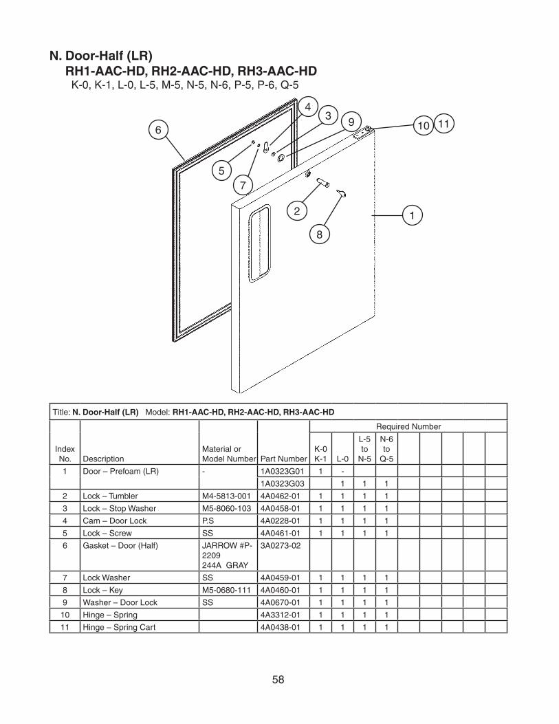
N. Door-Half (LR)RH1-AAC-HD, RH2-AAC-HD, RH3-AAC-HD
K-0, K-1, L-0, L-5, M-5, N-5, N-6, P-5, P-6, Q-5
Title: N. Door-Half (LR) Model: RH1-AAC-HD, RH2-AAC-HD, RH3-AAC-HD
Index No. Description
Material or Model Number Part Number
Required Number
K-0 K-1 L-0
L-5 to
N-5
N-6 to
Q-5
1 Door – Prefoam (LR) - 1A0323G01 1 -
1A0323G03 1 1 1
2 Lock – Tumbler M4-5813-001 4A0462-01 1 1 1 1
3 Lock – Stop Washer M5-8060-103 4A0458-01 1 1 1 1
4 Cam – Door Lock P.S 4A0228-01 1 1 1 1
5 Lock – Screw SS 4A0461-01 1 1 1 1
6 Gasket – Door (Half) JARROW #P-2209244A GRAY
3A0273-02
7 Lock Washer SS 4A0459-01 1 1 1 1
8 Lock – Key M5-0680-111 4A0460-01 1 1 1 1
9 Washer – Door Lock SS 4A0670-01 1 1 1 1
10 Hinge – Spring 4A3312-01 1 1 1 1
11 Hinge – Spring Cart 4A0438-01 1 1 1 1
7
4
5
3
2
8
1
69 10 11

59
P. Door-Half (UL)RH2-AAC-HD, RH3-AAC-HD
K-0, L-5, N-5, N-6, P-5, P-6, Q-5
Title: P. Door-Half (UL) Model: RH2-AAC-HD, RH3-AAC-HD
Index No. Description
Material or Model Number Part Number
Required Number
K-0
L-5to
Q-5
1 Door – Prefoam (UL) - 1A0323G02 1 -
1A0323G04 1
2 Lock – Tumbler M4-5813-001 4A0462-01 1 1
3 Lock – Stop Washer M5-8060-103 4A0458-01 1 1
4 Cam – Door Lock P.S 4A0228-01 1 1
5 Lock – Screw SS 4A0461-01 1 1
6 Gasket – Door (Half) JARROW #P-2209244A GRAY
3A0273-02 1 1
7 Lock Washer SS 4A0459-01 1 1
8 Lock – Key M5-0680-111 4A0460-01 1 1
9 Washer – Door Lock SS 4A0670-01 1 1
10 Hinge – Spring 4A3312-02 1 1
11 Hinge – Spring Cart 4A0438-02 1 1
7
4
5
3
2
8
1
610
9
11

60
Q. Door-Half (LL)RH2-AAC-HD, RH3-AAC-HD
K-0, L-5, N-5, N-6, P-5, P-6, Q-5
Title: Q. Door-Half (LL) Model: RH2-AAC-HD, RH3-AAC-HD
Index No. Description
Material or Model Number Part Number
Required Number
K-0
L-5to
Q-5
1 Door – Prefoam (LL) - 1A0325G02 1 -
1A0325G04 1
2 Lock – Tumbler M4-5813-001 4A0462-01 1 1
3 Lock – Stop Washer M5-8060-103 4A0458-01 1 1
4 Cam – Door Lock P.S 4A0228-01 1 1
5 Lock – Screw SS 4A0461-01 1 1
6 Gasket – Door (Half) JARROW #P-2209244A GRAY
3A0273-02 1 1
7 Lock Washer SS 4A0459-01 1 1
8 Lock – Key M5-0680-111 4A0460-01 1 1
9 Washer – Door Lock SS 4A0670-01 1 1
10 Hinge – Spring - 4A3312-02 1 1
11 Hinge – Spring Cart 4A0438-02 1 1
7
45
3
28
1
610 911

61
R. Mullion-HorizontalRH1-AAC-HD
K-0, K-1, L-0, L-5, M-5, N-6, P-5, P-6, Q-5
Title: R. Mullion-Horizontal Model: RH1-AAC-HD
Index No. Description
Material or Model Number Part Number
Required Number
K-0 to
Q-5
1 Mullion – Prefoam (H) - 2A1313G02 1
2 Plate – Strike (Front) SS 4A0355-01 1
2a Truss Head Screw 4×8, SS 7C32-0408 1
3 Plate – Strike (Base) SS 4A0354-01 1
3a T2 Screw 4×8, SS 7P32-0408 2
1
2a23a3

62
S. Mullion-VerticalRH2-AAC, RH3-AAC
K-0, L-0, L-5, M-5, M-6, M-7, N-5, N-6, P-5, P-6, P-7, Q-5
M-6 and earlier
The santoprene light socket was changed to a porcelain lampholder at M-7. This change is non-interchangeable. If the light socket is not operating on a unit with a santoprene light socket, Hoshizaki recommends replacement with HS-3554.
Note:
Parts 5, 6 and 6a are not included in HS-3554; they are shown for reference only.
HS1
5
6a6
HS2
HS1a
HS2a
1
2a2
3a3
4a4
M-7 and later
8
5
6a6
7

63
Title: S. Mullion-Vertical Model: RH2-AAC, RH3-AAC
Index No. Description
Material or Model Number Part Number
Required Number
K-0to
L-5M-5M-6
M-7 to
P-6P-7Q-5
1 Mullion – Prefoam - 2A1288G03 1 1 1
2 Pilaster – Mullion AL 2A0205-21 2 2 2 -
2A3246-21 2
2a Truss Head Screw 5×10, SS 7C32-0510 6 6 6 6
3 Plate – Strike (Front) SS 4A0355-01 1 1 1 1
3a Truss Head Screw 4×8, SS 7C32-0408 1 1 1 1
4 Plate – Strike (Base) SS 4A0354-01 1 1 1 1
4a T2 Screw 4×8, SS 7P32-0408 2 2 2 2
5 Bulb – Light GE, 40A15 4A0437-01 1 -
- 4A2420-01 1 1 1
6 Shield – Light 2778-1010-3000
4A0465-01 1 1 1 1
6a Cheese Head Screw 5×12, SS 7C52-0512 2 2 2 2
6b Washer 8, SS 7W22-0800 2 2 -
7 Threaded Insert (Wide) 4A0839-01 Non-interchangeable part change. If light socket is not operating for these codes, Hoshizaki recommends replacement with HS-3554 (below).
2 2
8 Lampholder - 4A2862-01 1 1
HS-3554-Lampholder Conversion Kit
Index No. Description
Material or Model Number Part Number
Required Number
M-6 and earlier
HS1 Plate – Lampholder Mount SS 4A2880-01 1
HS1a Cheese Head Screw SS 7C52-0512 2
HS2 Lampholder 4A2862-01 1
HS2a Terminal – Flag DNFR18-250FIBK
8101-18FJ 2

64
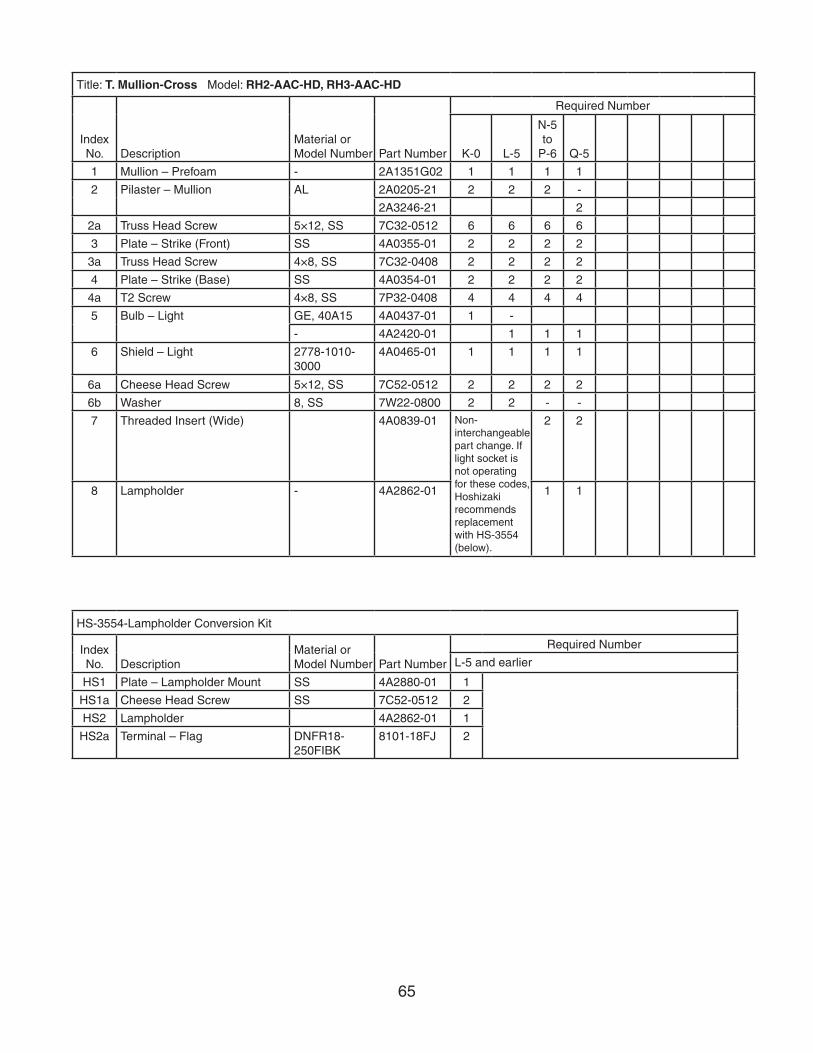
T. Mullion-CrossRH2-AAC-HD, RH3-AAC-HD
K-0, L-5, N-5, N-6, P-5, P-6, Q-5
L-5 and earlier
The santoprene light socket was changed to a porcelain lampholder at N-5. This change is non-interchangeable. If the light socket is not operating on a unit with a santoprene light socket, Hoshizaki recommends replacement with HS-3554.
Note:
Parts 5, 6 and 6a are not included in HS-3554; they are shown for reference only.
HS1
5
6a6
HS2
HS1a
HS2a
N-5 and later
8
5
6a6
7
1
2a2
4a4
3a3
4a4
3a3
65
Title: T. Mullion-Cross Model: RH2-AAC-HD, RH3-AAC-HD
Index No. Description
Material or Model Number Part Number
Required Number
K-0 L-5
N-5to
P-6 Q-5
1 Mullion – Prefoam - 2A1351G02 1 1 1 1
2 Pilaster – Mullion AL 2A0205-21 2 2 2 -
2A3246-21 2
2a Truss Head Screw 5×12, SS 7C32-0512 6 6 6 6
3 Plate – Strike (Front) SS 4A0355-01 2 2 2 2
3a Truss Head Screw 4×8, SS 7C32-0408 2 2 2 2
4 Plate – Strike (Base) SS 4A0354-01 2 2 2 2
4a T2 Screw 4×8, SS 7P32-0408 4 4 4 4
5 Bulb – Light GE, 40A15 4A0437-01 1 -
- 4A2420-01 1 1 1
6 Shield – Light 2778-1010-3000
4A0465-01 1 1 1 1
6a Cheese Head Screw 5×12, SS 7C52-0512 2 2 2 2
6b Washer 8, SS 7W22-0800 2 2 - -
7 Threaded Insert (Wide) 4A0839-01 Non-interchangeable part change. If light socket is not operating for these codes, Hoshizaki recommends replacement with HS-3554 (below).
2 2
8 Lampholder - 4A2862-01 1 1
HS-3554-Lampholder Conversion Kit
Index No. Description
Material or Model Number Part Number
Required Number
L-5 and earlier
HS1 Plate – Lampholder Mount SS 4A2880-01 1
HS1a Cheese Head Screw SS 7C52-0512 2
HS2 Lampholder 4A2862-01 1
HS2a Terminal – Flag DNFR18-250FIBK
8101-18FJ 2

66
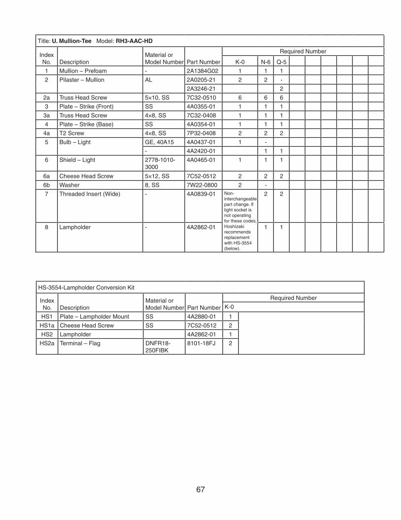
U. Mullion-TeeRH3-AAC-HD
K-0, N-6, Q-5
K-0
The santoprene light socket was changed to a porcelain lampholder at N-6. This change is non-interchangeable. If the light socket is not operating on a unit with a santoprene light socket, Hoshizaki recommends replacement with HS-3554.
Note:
Parts 5, 6 and 6a are not included in HS-3554; they are shown for reference only.
HS1
5
6a6
HS2
HS1a
HS2a
N-6 and later
8
5
6a6
7
1
2a2
4a4
3a3
67
Title: U. Mullion-Tee Model: RH3-AAC-HD
Index No. Description
Material or Model Number Part Number
Required Number
K-0 N-6 Q-5
1 Mullion – Prefoam - 2A1384G02 1 1 1
2 Pilaster – Mullion AL 2A0205-21 2 2 -
2A3246-21 2
2a Truss Head Screw 5×10, SS 7C32-0510 6 6 6
3 Plate – Strike (Front) SS 4A0355-01 1 1 1
3a Truss Head Screw 4×8, SS 7C32-0408 1 1 1
4 Plate – Strike (Base) SS 4A0354-01 1 1 1
4a T2 Screw 4×8, SS 7P32-0408 2 2 2
5 Bulb – Light GE, 40A15 4A0437-01 1 -
- 4A2420-01 1 1
6 Shield – Light 2778-1010-3000
4A0465-01 1 1 1
6a Cheese Head Screw 5×12, SS 7C52-0512 2 2 2
6b Washer 8, SS 7W22-0800 2 -
7 Threaded Insert (Wide) - 4A0839-01 Non-interchangeable part change. If light socket is not operating for these codes, Hoshizaki recommends replacement with HS-3554 (below).
2 2
8 Lampholder - 4A2862-01 1 1
HS-3554-Lampholder Conversion Kit
Index No. Description
Material or Model Number Part Number
Required Number
K-0
HS1 Plate – Lampholder Mount SS 4A2880-01 1
HS1a Cheese Head Screw SS 7C52-0512 2
HS2 Lampholder 4A2862-01 1
HS2a Terminal – Flag DNFR18-250FIBK
8101-18FJ 2

68
V. Label LocationRH1-AAC(-HD)
K-0, K-1, L-0, L-5, M-5, M-6, M-7, N-5, N-6, P-5, P-6, P-7, Q-5
Title: V. Label Location Model: RH1-AAC(-HD)
Index No. Description
Material or Model Number Part Number
Required Number
K-0 to
Q-5
1 Label – Penguin HA (L) - 4A0526-02 1
2 Emblem – Hoshizaki - 4A0560-01 1
3 Label – Door Heater Switch PVC FILM 4A1039-01 1
4 Caution Label PVC FILM 4A1931-01 1
5 Wiring Diagram PVC FILM 2A2350-01 1
6 Label – R134a - 444463-01 1
7 Label – Power - 4A2196-01 1
8 Label – Display - 4A2198-01 1
9 Cover – Nameplate - 4A3727-01 1
1
2
3
7
8
96
5
4

69
V. Label LocationRH2-AAC(-HD)
K-0, L-5, M-5, M-6, M-7, N-5, N-6, P-5, P-6, P-7, Q-5
Title: V. Label Location Model: RH2-AAC(-HD)
Index No. Description
Material or Model Number Part Number
Required Number
K-0 to
Q-5
1 Label – Penguin-ha(L) - 4A0526-02 1
2 Emblem – Hoshizaki - 4A0560-01 1
3 Label – Door Heater Switch PVC FILM 4A1039-01 1
4 Caution Label PVC FILM 4A1931-01 1
5 Wiring Diagram PVC FILM 2A2352-01 1
6 Label – R134a - 444463-01 1
7 Label – Power - 4A2196-01 1
8 Label – Display - 4A2198-01 1
9 Label – Warning - 4A2968-01 1
10 Cover – Nameplate - 4A3727-01 1
VIEW A7
3
4
51
6
82
10
WARNING LABEL VIEW
9

70
V. Label LocationRH3-AAC(-HD)
K-0, L-0, L-5, M-5, M-6, M-7, N-5, N-6, P-5, Q-5
Title: V. Label Location Model: RH3-AAC(-HD)
Index No. Description
Material or Model Number Part Number
Required Number
K-0 to
N-6
1 Label – Penguin HA (L) - 4A0526-02 1
2 Emblem – Hoshizaki - 4A0560-01 1
3 Label – Door Heater Switch PVC FILM 4A1039-01 1
4 Caution Label PVC FILM 4A1931-01 1
5 Wiring Diagram PVC FILM 2A2354-01 1
6 Label – R134a - 444463-01 1
7 Label – Power - 4A2196-01 1
8 Label – Display - 4A2198-01 1
9 Label – Warning - 4A2968-01 1
10 Cover – Nameplate - 4A3727-01 1
VIEW A7
3
4
51
6
8
2
10
9
WARNING LABEL VIEW

71
Title: W. Literature & Packaging Model: RH1-AAC(-HD), RH2-AAC(-HD), RH3-AAC(-HD)
Index No. Description
Material or Model Number Part Number
Required Number
K-0 to
P-7 Q-5
1 Instruction Manual Paper 91A34010L 1 1
Packaging (available only for models currently in production)
RH1-AAC 1A0765A04 1 1
RH1-AAC-HD 1A0765A05 1 1
RH2-AAC 1A0766A06 1 1
RH2-AAC-HD 1A0766A07 1 1
RH3-AAC 1A0767A06 1 1
RH3-AAC-HD 1A0767A07 1 1
1 Filler – Door 4A2977-01 2 2
2 Pad – Corner 3A2598-01 4 4
3 Post – Corner 3A2603-01 4 4
4 Support – Corner 3A2596-01 4 4
5 T2 Screw 4×8, SS 7P32-0408 4 4
6 Bracket (A) – Overflow Pan 4A0878-01 1 1
7 Bracket (B) – Overflow Pan 4A0879-01 1 1
8 Pan – Overflow 4A2081-01 1 -
4A3419G01 1
9 Stop – Door 4A1873-01 1 1
10 Flat Washer 7W21I5800 4 4
11 Hex Head Bolt 7B01 I5825 4 4
12 Pallet 3A1814-01 1 1
13 Door Stop – Center Half-Door Models Only
4A1874-01 1 1
14 Protector – Front RH2-AAC(-HD)RH3-AAC(-HD)
3A2595-01 1 1
W. Literature & PackagingRH1-AAC(-HD), RH2-AAC(-HD), RH3-AAC(-HD)
K-0, K-1, L-0, L-5, M-5, M-6, M-7, N-5, N-6, P-5, P-6, P-7, Q-5


![##[1]. 마케팅 용어집(0408)_검수전](https://static.fdocuments.net/doc/165x107/557209ef497959fc0b8bf9db/1-0408.jpg)

