- Squarespacestatic1.squarespace.com/.../Airlift+DOA+Catalogue.R10.14.pdf · Updated June 2014....
56
www.airlift.no
Transcript of - Squarespacestatic1.squarespace.com/.../Airlift+DOA+Catalogue.R10.14.pdf · Updated June 2014....

www.airlift.no
Part-21
Modifications Catalogue
for
AgustaWestland
Airbus Helicopters
Edition: October 2014
AIRLIFT AS
Førde Airport, N-6977 Bygstad, Norway
EASA.21J.315 [email protected]
www.airlift-doa.com
For Table of Contents see PDF’s Bookmarks.
Product brochures filed here are sorted per aircraft manufacturer, aircraft model and ATA
chapter.
For modifications listed in the following Modifications List but not yet presented as brochure
in this catalogue, please visit our website or contact us at [email protected] or call +47 57
71 81 00.
To download latest edition of this catalogue, please visit www.airlift-doa.com
Airlift AS, Førde Airport, 6977 Bygstad, Norway | Tel: +47 57 71 81 00 | Fax: +47 57 71 81 01 | [email protected] www.airlift.no
Airlift AS, based at Forde Airport in Bygstad, Norway, is the largest North European onshore helicopter company with longstanding operation in heavy lifting and search and rescue (SAR) both in European domestic market as well as in the Arctic. The company is part of the Blueway Group and operates 16 of the group’s helicopters. Airlift's technical department has more than 20 years of experience with maintenance, design and modification of helicopters. In addition to performing design and maintenance on the company's own helicopters, Airlift has also provided design, installation, maintenance and CAMO services to other helicopter companies. Since December 2007 Airlift holds an EASA Part-21 Subpart J approval as approved Design Organisation (DOA) (Approval ref. EASA.21J.315). This includes approval of design changes related to avionics, electrical and interiors as well as changes and minor repairs related to aircraft structure, approval of Flight Conditions and issue of Permit to Fly approvals. Airlift DOA experienced staff includes Design Engineers, Certification Verification Engineers, Flight Test Pilots and Flight Test Engineers. Since its initial approval, Airlift DOA has certified over 80 minor changes and is holder of 15 EASA approved Supplemental Type Certificates (STC). The main area of expertise of Airlift DOA are the development, installation, testing and certification of:
Night Vision Imaging Systems (NVIS)
Emergency Medical Services (EMS)
Survey / Mission Equipment
Avionic and Electrical modifications Moreover Airlift, as operator, has over 20 years of experience from EMS and SAR operations as well as over 15 years of experience from NVIS operations with AS365 and AS332 helicopters on the mainland and in the Arctic (Svalbard archipelago). Airlift DOA has, over the years, worked on the following helicopter types:
Airbus Helicopters o AS332 / EC225 Super Puma (incl. 2 STC) o AS365 / EC155 Dauphin (incl. 6 STC) o BK117 / EC145 (incl. 1 STC) o EC135 o AS350 / EC130 (incl. 4 STC)
AgustaWestland o AW139 (incl. 2 STC)
Airlift AS, Førde Airport, 6977 Bygstad, Norway | Tel: +47 57 71 81 00 | Fax: +47 57 71 81 01 | [email protected] www.airlift.no
Alongside to modifications developed for Airlift operator, the DOA has developed many STC and minor changes for customers in Europe as well as around the world (namely including up to Peru and New Zealand!) Many of the EMS and NVIS STC's were developed on request of the major actors in EMS and SAR operations in Scandinavia and UK. Airlift DOA customers includes operators, MRO facilities as well as component manufacturers. Visit www.airlift-doa.com for more information. Contact us to see how we can help you!
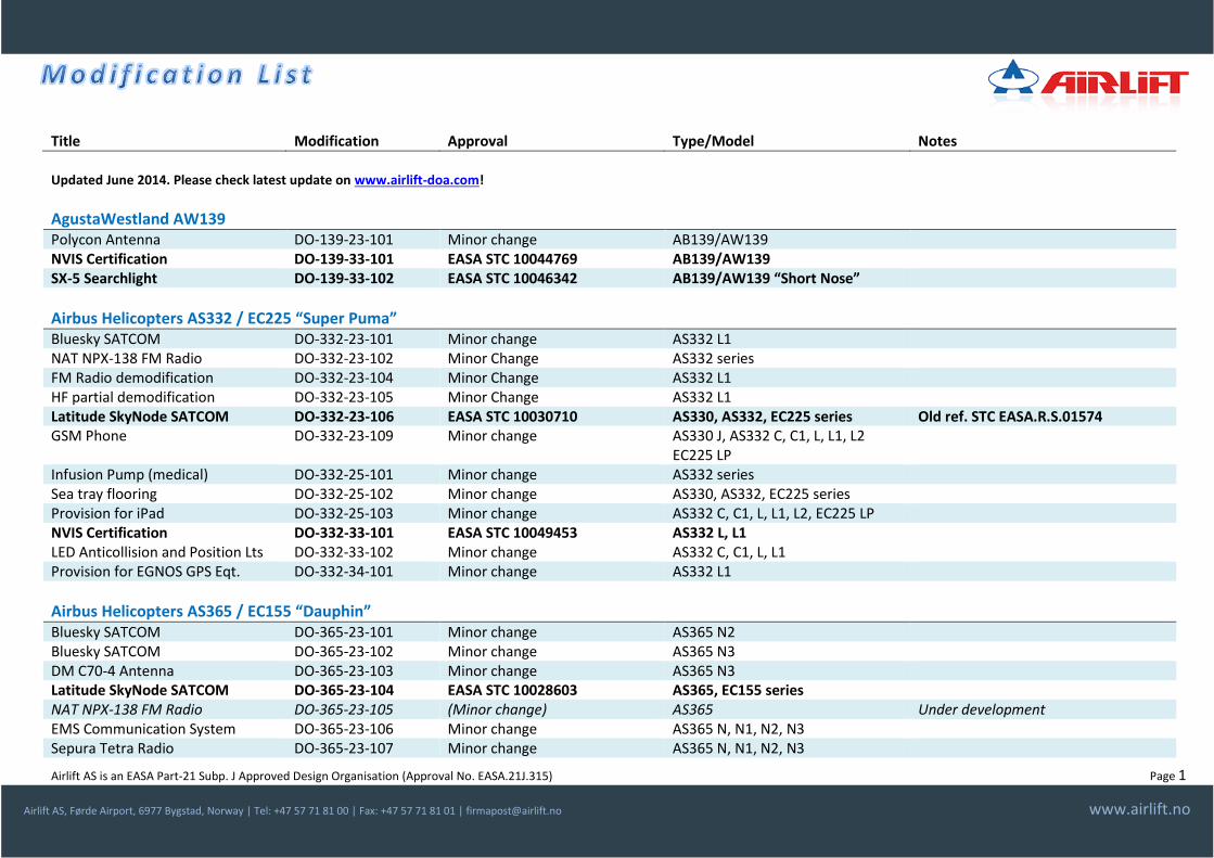
Title Modification Approval Type/Model Notes
Airlift AS is an EASA Part-21 Subp. J Approved Design Organisation (Approval No. EASA.21J.315) Page 1
Airlift AS, Førde Airport, 6977 Bygstad, Norway | Tel: +47 57 71 81 00 | Fax: +47 57 71 81 01 | [email protected] www.airlift.no
Updated June 2014. Please check latest update on www.airlift-doa.com!
AgustaWestland AW139 Polycon Antenna DO-139-23-101 Minor change AB139/AW139 NVIS Certification DO-139-33-101 EASA STC 10044769 AB139/AW139 SX-5 Searchlight DO-139-33-102 EASA STC 10046342 AB139/AW139 “Short Nose”
Airbus Helicopters AS332 / EC225 “Super Puma” Bluesky SATCOM DO-332-23-101 Minor change AS332 L1 NAT NPX-138 FM Radio DO-332-23-102 Minor Change AS332 series FM Radio demodification DO-332-23-104 Minor Change AS332 L1 HF partial demodification DO-332-23-105 Minor Change AS332 L1 Latitude SkyNode SATCOM DO-332-23-106 EASA STC 10030710 AS330, AS332, EC225 series Old ref. STC EASA.R.S.01574 GSM Phone DO-332-23-109 Minor change AS330 J, AS332 C, C1, L, L1, L2
EC225 LP
Infusion Pump (medical) DO-332-25-101 Minor change AS332 series Sea tray flooring DO-332-25-102 Minor change AS330, AS332, EC225 series Provision for iPad DO-332-25-103 Minor change AS332 C, C1, L, L1, L2, EC225 LP NVIS Certification DO-332-33-101 EASA STC 10049453 AS332 L, L1 LED Anticollision and Position Lts DO-332-33-102 Minor change AS332 C, C1, L, L1 Provision for EGNOS GPS Eqt. DO-332-34-101 Minor change AS332 L1
Airbus Helicopters AS365 / EC155 “Dauphin” Bluesky SATCOM DO-365-23-101 Minor change AS365 N2 Bluesky SATCOM DO-365-23-102 Minor change AS365 N3 DM C70-4 Antenna DO-365-23-103 Minor change AS365 N3 Latitude SkyNode SATCOM DO-365-23-104 EASA STC 10028603 AS365, EC155 series NAT NPX-138 FM Radio DO-365-23-105 (Minor change) AS365 Under development EMS Communication System DO-365-23-106 Minor change AS365 N, N1, N2, N3 Sepura Tetra Radio DO-365-23-107 Minor change AS365 N, N1, N2, N3
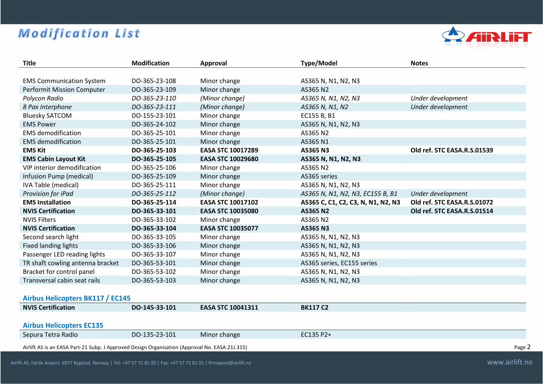
Title Modification Approval Type/Model Notes
Airlift AS is an EASA Part-21 Subp. J Approved Design Organisation (Approval No. EASA.21J.315) Page 2
Airlift AS, Førde Airport, 6977 Bygstad, Norway | Tel: +47 57 71 81 00 | Fax: +47 57 71 81 01 | [email protected] www.airlift.no
EMS Communication System DO-365-23-108 Minor change AS365 N, N1, N2, N3 Performit Mission Computer DO-365-23-109 Minor change AS365 N2 Polycon Radio DO-365-23-110 (Minor change) AS365 N, N1, N2, N3 Under development 8 Pax Interphone DO-365-23-111 (Minor change) AS365 N, N1, N2 Under development Bluesky SATCOM DO-155-23-101 Minor change EC155 B, B1 EMS Power DO-365-24-102 Minor change AS365 N, N1, N2, N3 EMS demodification DO-365-25-101 Minor change AS365 N2 EMS demodification DO-365-25-101 Minor change AS365 N1 EMS Kit DO-365-25-103 EASA STC 10017289 AS365 N3 Old ref. STC EASA.R.S.01539 EMS Cabin Layout Kit DO-365-25-105 EASA STC 10029680 AS365 N, N1, N2, N3 VIP interior demodification DO-365-25-106 Minor change AS365 N2 Infusion Pump (medical) DO-365-25-109 Minor change AS365 series IVA Table (medical) DO-365-25-111 Minor change AS365 N, N1, N2, N3 Provision for iPad DO-365-25-112 (Minor change) AS365 N, N1, N2, N3, EC155 B, B1 Under development EMS Installation DO-365-25-114 EASA STC 10017102 AS365 C, C1, C2, C3, N, N1, N2, N3 Old ref. STC EASA.R.S.01072 NVIS Certification DO-365-33-101 EASA STC 10035080 AS365 N2 Old ref. STC EASA.R.S.01514 NVIS Filters DO-365-33-102 Minor change AS365 N2 NVIS Certification DO-365-33-104 EASA STC 10035077 AS365 N3 Second search light DO-365-33-105 Minor change AS365 N, N1, N2, N3 Fixed landing lights DO-365-33-106 Minor change AS365 N, N1, N2, N3 Passenger LED reading lights DO-365-33-107 Minor change AS365 N, N1, N2, N3 TR shaft cowling antenna bracket DO-365-53-101 Minor change AS365 series, EC155 series Bracket for control panel DO-365-53-102 Minor change AS365 N, N1, N2, N3 Transversal cabin seat rails DO-365-53-103 Minor change AS365 N, N1, N2, N3
Airbus Helicopters BK117 / EC145 NVIS Certification DO-145-33-101 EASA STC 10041311 BK117 C2
Airbus Helicopters EC135 Sepura Tetra Radio DO-135-23-101 Minor change EC135 P2+

Title Modification Approval Type/Model Notes
Airlift AS is an EASA Part-21 Subp. J Approved Design Organisation (Approval No. EASA.21J.315) Page 3
Airlift AS, Førde Airport, 6977 Bygstad, Norway | Tel: +47 57 71 81 00 | Fax: +47 57 71 81 01 | [email protected] www.airlift.no
Provision for mini-iPad DO-135-25-101 (Minor change) EC135 Under development
Airbus Helicopters AS350 / EC130 Bluesky SATCOM DO-350-23-101
DO-350-23-106 Minor change AS350 B2, B3
GSM Phone DO-350-23-102 DO-350-23-109
Minor change AS350 series
NAT NPX-138 FM Radio DO-350-23-103 DO-350-23-104 DO-350-23-105
Minor Change AS350 B2, B3
Latitude SkyNode SATCOM DO-350-23-110 Minor change AS350 B2, B3, EC130 B4 UHF Radio DO-350-23-111 Minor change AS350 B2, B3 Lead-acid Main Battery DO-350-24-101 EASA STC 10044362 AS350 B, BA, B1, B2, B3 TC Canada and Brasil validated Life Vest Holder DO-350-25-102 Minor change AS350 series Long Line Release Switch DO-350-25-103
DO-130-25-101 Minor change AS350 B2, B3, EC130 B4
Garmin 296 GPS DO-350-25-105 Minor change AS350 B2, B3 Power Utility Outlets DO-350-25-106 Minor change AS350 series Geophysical Equipment DO-350-25-107 EASA STC 10032471 AS350 B, BA, B1, B2, B3 Cockpit Manual and Charts Holder DO-350-25-108 (Minor change) AS350, EC130 Under development First Aid Kit Holder DO-350-25-109 Minor change AS350 series Removable External Mount DO-350-25-115 EASA STC 10043743 AS350 B, BA, B1, B2, B3 Nose Equipment Pod DO-350-25-116 Minor change AS350 B, BA, B1, B2, B3 Provision for mini-iPad DO-350-25-117 Minor change AS350 B2, B3 Flight Data Monitor DO-350-25-119 (Minor change) AS350, EC130 Under development LED Position and Anti-collision LT DO-350-33-101 Minor change AS350 B1, B2, B3 Alternate Static Pressure source DO-350-34-101 (Minor change) AS350, EC130 Under development Digital Horizon RCA2600-3 DO-350-34-103 Minor change AS350 B, BA, B1, B2, B3 Radar Altimeter KRA-405B DO-130-34-100 EASA STC 10036162 AS350 B1, B2, B3, EC130 B4 DZUS Rail on Instrument Panel DO-350-53-101, 102 Minor change AS350 B2, B3
Title Modification Approval Type/Model Notes
Airlift AS is an EASA Part-21 Subp. J Approved Design Organisation (Approval No. EASA.21J.315) Page 4
Airlift AS, Førde Airport, 6977 Bygstad, Norway | Tel: +47 57 71 81 00 | Fax: +47 57 71 81 01 | [email protected] www.airlift.no
Sikorsky S-92 IV Bag holder (medical) DO-S92-25-101 (Minor change) S92 Under development
CONTACT INFORMATION For order placement or request of information contact Airlift AS Design Organisation at +47 57 71 81 00 or via email at [email protected] or visit our website www.airlift-doa.com.
For a complete catalogue of our EASA Part-21 Approved Changes visit: www.airlift-doa.com

Modification Proposal - Doc. MP-000-33-NVIS-01 Rev. 9/2014, dated 29 Sep. 2014
Airlift AS, Førde Airport, 6977 Bygstad, Norway | Tel: +47 57 71 81 00 | Fax: +47 57 71 81 01 | [email protected] www.airlift.no
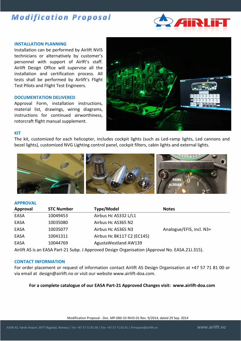
NIGHT VISION IMAGING SYSTEM (NVIS) DESCRIPTION Installation and certification of Night Vision Imaging Systems. The modification comprehends of the installation of cockpit, cabin, external lighting system for use with Night Vision Goggles (NVG). The certification (of each helicopter) includes extensive ground and flight testing carried out with Airlift’s qualified flight test crews. Airlift, as an operator, has 15 years of experience from NVG operations with AS332 and AS365 in Search and Rescue Operations in the Artic. Airlift holds 5 Supplemental Type Certificates (STC) approved by the EASA according to the latest EASA/FAA NVIS Certification Standards, for:
Airbus Helicopters AS332 L/L1
Airbus Helicopters AS365 N2/N3
Airbus Helicopters EC145 C2
AgustaWestland AW139. As per September 2014 Airlift has modified and certified 13 helicopters (plus 4 more under work) for the following customers:
Airlift (AS365/SAR), Norway
Norsk Luftambulanse (EC145/EMS), Norway
Lufttransport (AS332/SAR, AS365/LOS, AW139/EMS), Norway
SAAB and Scandinavian MediCopter (AS365/EMS, EC145/EMS), Sweden/Denmark
Heli-One (Norway) for the Icelandic Coast Guard (AS332/SAR), Iceland Each installation is customized for each helicopter and cover instrument panel lighting, cockpit lighting, cabin lighting and external lighting. The installation comprehends installation of NVG compatible lights or installation of NVG filters as necessary. NVG lighting is controlled by a dedicated NVG lighting control panel customized and programmed for the specific lighting harmonization of the helicopter. Alternatively certifications of “NVG friendly” helicopters, delivered from manufacturers, can be performed.
Modification Proposal - Doc. MP-000-33-NVIS-01 Rev. 9/2014, dated 29 Sep. 2014
Airlift AS, Førde Airport, 6977 Bygstad, Norway | Tel: +47 57 71 81 00 | Fax: +47 57 71 81 01 | [email protected] www.airlift.no
INSTALLATION PLANNING Installation can be performed by Airlift NVIS technicians or alternatively by customer’s personnel with support of Airlft’s staff. Airlift Design Office will supervise all the installation and certification process. All tests shall be performed by Airlift’s Flight Test Pilots and Flight Test Engineers. DOCUMENTATION DELIVERED Approval Form, installation instructions, material list, drawings, wiring diagrams, instructions for continued airworthiness, rotorcraft flight manual supplement. KIT The kit, customized for each helicopter, includes cockpit lights (such as Led-ramp lights, Led cannons and bezel lights), customized NVG Lighting control panel, cockpit filters, cabin lights and external lights.
APPROVAL Approval STC Number Type/Model Notes
EASA 10049453 Airbus Hc AS332 L/L1
EASA 10035080 Airbus Hc AS365 N2
EASA 10035077 Airbus Hc AS365 N3 Analogue/EFIS, incl. N3+
EASA 10041311 Airbus Hc BK117 C2 (EC145)
EASA 10044769 AgustaWestland AW139
Airlift AS is an EASA Part-21 Subp. J Approved Design Organisation (Approval No. EASA.21J.315). CONTACT INFORMATION For order placement or request of information contact Airlift AS Design Organisation at +47 57 71 81 00 or via email at [email protected] or visit our website www.airlift-doa.com.
For a complete catalogue of our EASA Part-21 Approved Changes visit: www.airlift-doa.com
Modification Proposal - Doc. MP-139-33-102-01 Rev. 1/2013, dated 16 Sep 2013
Airlift AS, Førde Airport, 6977 Bygstad, Norway | Tel: +47 57 71 81 00 | Fax: +47 57 71 81 01 | [email protected] www.airlift.no
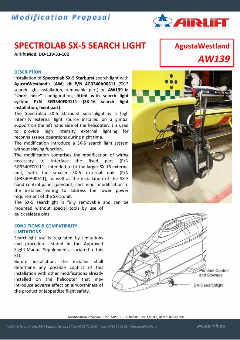
SPECTROLAB SX-5 SEARCH LIGHT Airlift Mod. DO-139-33-102 DESCRIPTION Installation of Spectrolab SX-5 Starburst search light with AgustaWestland’s (AW) kit P/N 4G3340A00611 (SX-5 search light installation, removable part) on AW139 in “short nose” configuration, fitted with search light system P/N 3G3340F00111 (SX-16 search light installation, fixed part). The Spectrolab SX-5 Starburst searchlight is a high intensity external light source installed on a gimbal support on the left hand side of the helicopter. It is used to provide high intensity external lighting for reconnaissance operations during night time. The modification introduce a SX-5 search light system without slaving function. The modification comprises the modification of wiring necessary to interface the fixed part (P/N 3G3340F00111), intended to fit the larger SX-16 external unit, with the smaller SX-5 external unit (P/N 4G3340A00611), as well as the installation of the SX-5 hand control panel (pendant) and minor modification to the installed wiring to address the lower power requirement of the SX-5 unit. The SX-5 searchlight is fully removable and can be mounted without special tools by use of quick release pins. CONDITIONS & COMPATIBILITY LIMITATIONS Searchlight use is regulated by limitations and procedures stated in the Approved Flight Manual Supplement associated to this STC. Before installation, the installer shall determine any possible conflict of this installation with other modifications already installed on the helicopter that may introduce adverse effect on airworthiness of the product or jeopardize flight safety.
AgustaWestland
AW139
Modification Proposal - Doc. MP-139-33-102-01 Rev. 1/2013, dated 16 Sep 2013
Airlift AS, Førde Airport, 6977 Bygstad, Norway | Tel: +47 57 71 81 00 | Fax: +47 57 71 81 01 | [email protected] www.airlift.no
INSTALLATION PLANNING Manpower: Mechanic / Sheet metal worker 30 hrs, Avionic 10 hrs. Complexity: medium.
DOCUMENTRATION DELIVERED Approval Form, installation instructions, material list, drawings, wiring diagrams, instructions for continued airworthiness, rotorcraft flight manual supplement.
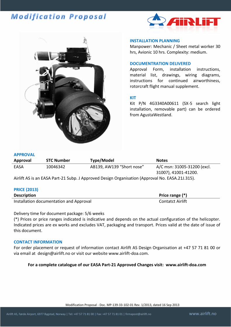
KIT Kit P/N 4G3340A00611 (SX-5 search light installation, removable part) can be ordered from AgustaWestland.
APPROVAL Approval STC Number Type/Model Notes
EASA 10046342 AB139, AW139 “Short nose” A/C msn: 31005-31200 (excl. 31007), 41001-41200.
Airlift AS is an EASA Part-21 Subp. J Approved Design Organisation (Approval No. EASA.21J.315). PRICE (2013) Description Price range (*)
Installation documentation and Approval Contatct Airlift
Delivery time for document package: 5/6 weeks (*) Prices or price ranges indicated is indicative and depends on the actual configuration of the helicopter. Indicated prices are ex works and excludes VAT, packaging and transport. Prices valid at the date of issue of this document. CONTACT INFORMATION For order placement or request of information contact Airlift AS Design Organisation at +47 57 71 81 00 or via email at [email protected] or visit our website www.airlift-doa.com.
For a complete catalogue of our EASA Part-21 Approved Changes visit: www.airlift-doa.com

Modification Proposal - Doc. MP-332-23-106-01 Rev. 1/2013, dated 01 Jul 2013
Airlift AS, Førde Airport, 6977 Bygstad, Norway | Tel: +47 57 71 81 00 | Fax: +47 57 71 81 01 | [email protected] www.airlift.no
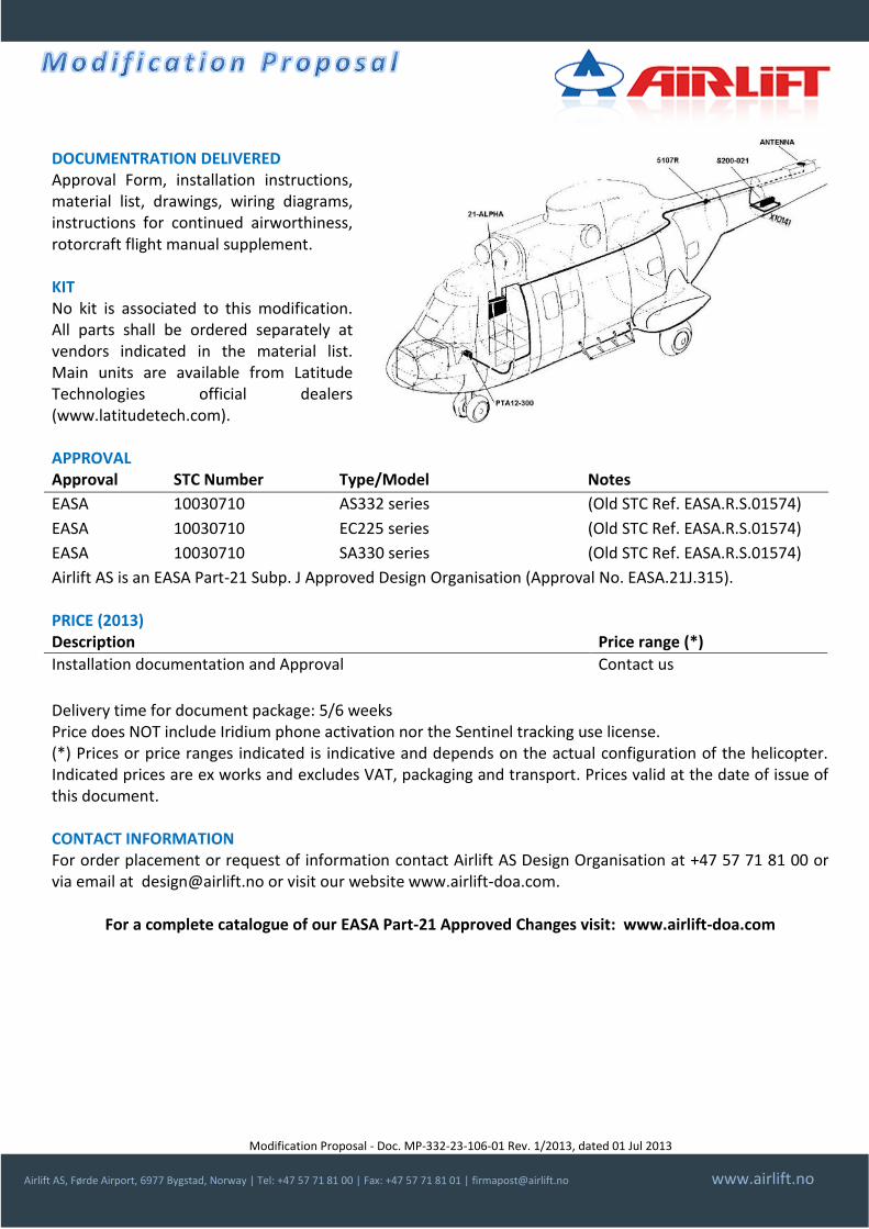
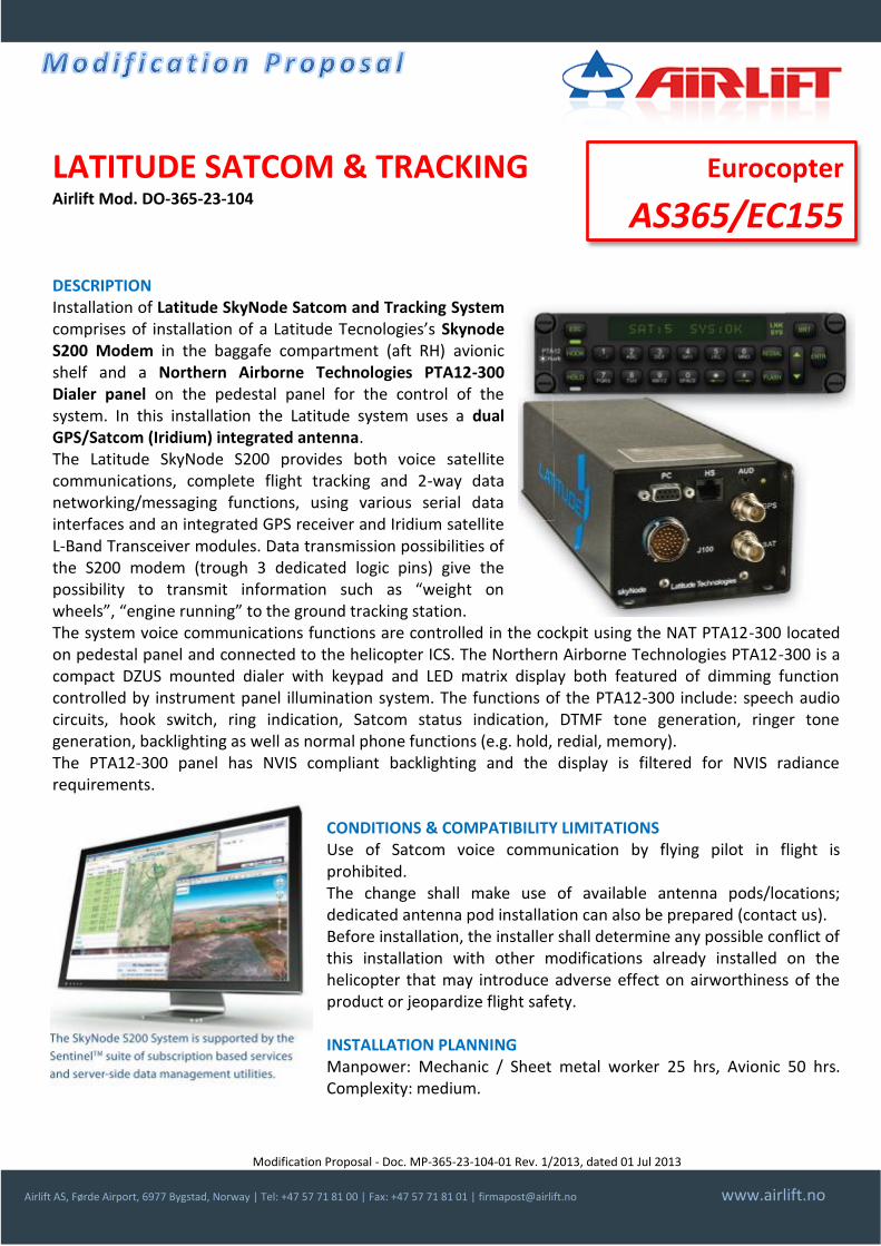
LATITUDE SATCOM & TRACKING Airlift Mod. DO-332-23-106 DESCRIPTION Installation of Latitude SkyNode Satcom and Traking System comprises of installation of a Latitude Tecnologies’s Skynode S200 Modem on a tailboom avionic shelf and a Northern Airborne Technologies PTA12-300 Dialer panel on the pedestal panel for the control of the system. In this installation the Latitude system uses a dual GPS/Satcom (Iridium) integrated antenna. The Latitude SkyNode S200 provides both voice satellite communications, complete flight tracking and 2-way data networking/messaging functions, using various serial data interfaces and an integrated GPS receiver and Iridium satellite L-Band Transceiver modules. Data transmission possibilities of the S200 modem (trough 3 dedicated logic pins) give the possibility to transmit information such as “weight on wheels”, “engine running” to the ground tracking station. The system voice communications functions are controlled in the cockpit using the NAT PTA12-300 located on pedestal panel and connected to the helicopter ICS. The Northern Airborne Technologies PTA12-300 is a compact DZUS mounted dialer with keypad and LED matrix display both featured of dimming function controlled by instrument panel illumination system. The functions of the PTA12-300 include: speech audio circuits, hook switch, ring indication, Satcom status indication, DTMF tone generation, ringer tone generation, backlighting as well as normal phone functions (e.g. hold, redial, memory). The PTA12-300 panel has NVIS compliant backlighting and the display is filtered for NVIS radiance requirements.
CONDITIONS & COMPATIBILITY LIMITATIONS Use of Satcom voice communication by flying pilot in flight is prohibited. The change shall make use of available antenna pods/locations; dedicated antenna pod installation can also be prepared (contact us). Before installation, the installer shall determine any possible conflict of this installation with other modifications already installed on the helicopter that may introduce adverse effect on airworthiness of the product or jeopardize flight safety.
INSTALLATION PLANNING Manpower: Mechanic / Sheet metal worker 30 hrs, Avionic 50 hrs. Complexity: medium.
Eurocopter
AS332/EC225 /SA330
Modification Proposal - Doc. MP-332-23-106-01 Rev. 1/2013, dated 01 Jul 2013
Airlift AS, Førde Airport, 6977 Bygstad, Norway | Tel: +47 57 71 81 00 | Fax: +47 57 71 81 01 | [email protected] www.airlift.no
DOCUMENTRATION DELIVERED Approval Form, installation instructions, material list, drawings, wiring diagrams, instructions for continued airworthiness, rotorcraft flight manual supplement. KIT No kit is associated to this modification. All parts shall be ordered separately at vendors indicated in the material list. Main units are available from Latitude Technologies official dealers (www.latitudetech.com). APPROVAL Approval STC Number Type/Model Notes
EASA 10030710 AS332 series (Old STC Ref. EASA.R.S.01574)
EASA 10030710 EC225 series (Old STC Ref. EASA.R.S.01574)
EASA 10030710 SA330 series (Old STC Ref. EASA.R.S.01574)
Airlift AS is an EASA Part-21 Subp. J Approved Design Organisation (Approval No. EASA.21J.315). PRICE (2013) Description Price range (*)
Installation documentation and Approval Contact us
Delivery time for document package: 5/6 weeks Price does NOT include Iridium phone activation nor the Sentinel tracking use license. (*) Prices or price ranges indicated is indicative and depends on the actual configuration of the helicopter. Indicated prices are ex works and excludes VAT, packaging and transport. Prices valid at the date of issue of this document. CONTACT INFORMATION For order placement or request of information contact Airlift AS Design Organisation at +47 57 71 81 00 or via email at [email protected] or visit our website www.airlift-doa.com.
For a complete catalogue of our EASA Part-21 Approved Changes visit: www.airlift-doa.com
Modification Proposal - Doc. MP-365-23-104-01 Rev. 1/2013, dated 01 Jul 2013
Airlift AS, Førde Airport, 6977 Bygstad, Norway | Tel: +47 57 71 81 00 | Fax: +47 57 71 81 01 | [email protected] www.airlift.no
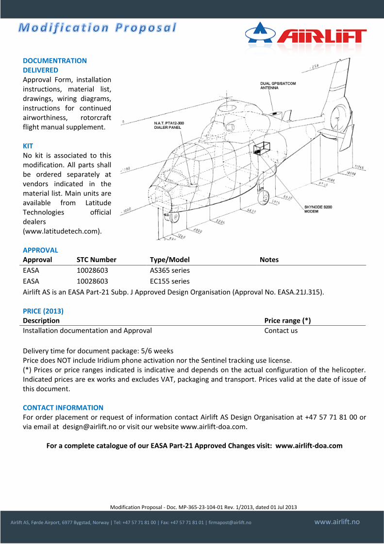
LATITUDE SATCOM & TRACKING Airlift Mod. DO-365-23-104 DESCRIPTION Installation of Latitude SkyNode Satcom and Tracking System comprises of installation of a Latitude Tecnologies’s Skynode S200 Modem in the baggafe compartment (aft RH) avionic shelf and a Northern Airborne Technologies PTA12-300 Dialer panel on the pedestal panel for the control of the system. In this installation the Latitude system uses a dual GPS/Satcom (Iridium) integrated antenna. The Latitude SkyNode S200 provides both voice satellite communications, complete flight tracking and 2-way data networking/messaging functions, using various serial data interfaces and an integrated GPS receiver and Iridium satellite L-Band Transceiver modules. Data transmission possibilities of the S200 modem (trough 3 dedicated logic pins) give the possibility to transmit information such as “weight on wheels”, “engine running” to the ground tracking station. The system voice communications functions are controlled in the cockpit using the NAT PTA12-300 located on pedestal panel and connected to the helicopter ICS. The Northern Airborne Technologies PTA12-300 is a compact DZUS mounted dialer with keypad and LED matrix display both featured of dimming function controlled by instrument panel illumination system. The functions of the PTA12-300 include: speech audio circuits, hook switch, ring indication, Satcom status indication, DTMF tone generation, ringer tone generation, backlighting as well as normal phone functions (e.g. hold, redial, memory). The PTA12-300 panel has NVIS compliant backlighting and the display is filtered for NVIS radiance requirements.
CONDITIONS & COMPATIBILITY LIMITATIONS Use of Satcom voice communication by flying pilot in flight is prohibited. The change shall make use of available antenna pods/locations; dedicated antenna pod installation can also be prepared (contact us). Before installation, the installer shall determine any possible conflict of this installation with other modifications already installed on the helicopter that may introduce adverse effect on airworthiness of the product or jeopardize flight safety.
INSTALLATION PLANNING Manpower: Mechanic / Sheet metal worker 25 hrs, Avionic 50 hrs. Complexity: medium.
Eurocopter
AS365/EC155
Modification Proposal - Doc. MP-365-23-104-01 Rev. 1/2013, dated 01 Jul 2013
Airlift AS, Førde Airport, 6977 Bygstad, Norway | Tel: +47 57 71 81 00 | Fax: +47 57 71 81 01 | [email protected] www.airlift.no
DOCUMENTRATION DELIVERED Approval Form, installation instructions, material list, drawings, wiring diagrams, instructions for continued airworthiness, rotorcraft flight manual supplement. KIT No kit is associated to this modification. All parts shall be ordered separately at vendors indicated in the material list. Main units are available from Latitude Technologies official dealers (www.latitudetech.com). APPROVAL Approval STC Number Type/Model Notes
EASA 10028603 AS365 series
EASA 10028603 EC155 series
Airlift AS is an EASA Part-21 Subp. J Approved Design Organisation (Approval No. EASA.21J.315). PRICE (2013) Description Price range (*)
Installation documentation and Approval Contact us
Delivery time for document package: 5/6 weeks Price does NOT include Iridium phone activation nor the Sentinel tracking use license. (*) Prices or price ranges indicated is indicative and depends on the actual configuration of the helicopter. Indicated prices are ex works and excludes VAT, packaging and transport. Prices valid at the date of issue of this document. CONTACT INFORMATION For order placement or request of information contact Airlift AS Design Organisation at +47 57 71 81 00 or via email at [email protected] or visit our website www.airlift-doa.com.
For a complete catalogue of our EASA Part-21 Approved Changes visit: www.airlift-doa.com
Modification Proposal - Doc. MP-365-25-EMS-01 Rev. 9/2014, dated 30 Sep 2014
Airlift AS, Førde Airport, 6977 Bygstad, Norway | Tel: +47 57 71 81 00 | Fax: +47 57 71 81 01 | [email protected] www.airlift.no
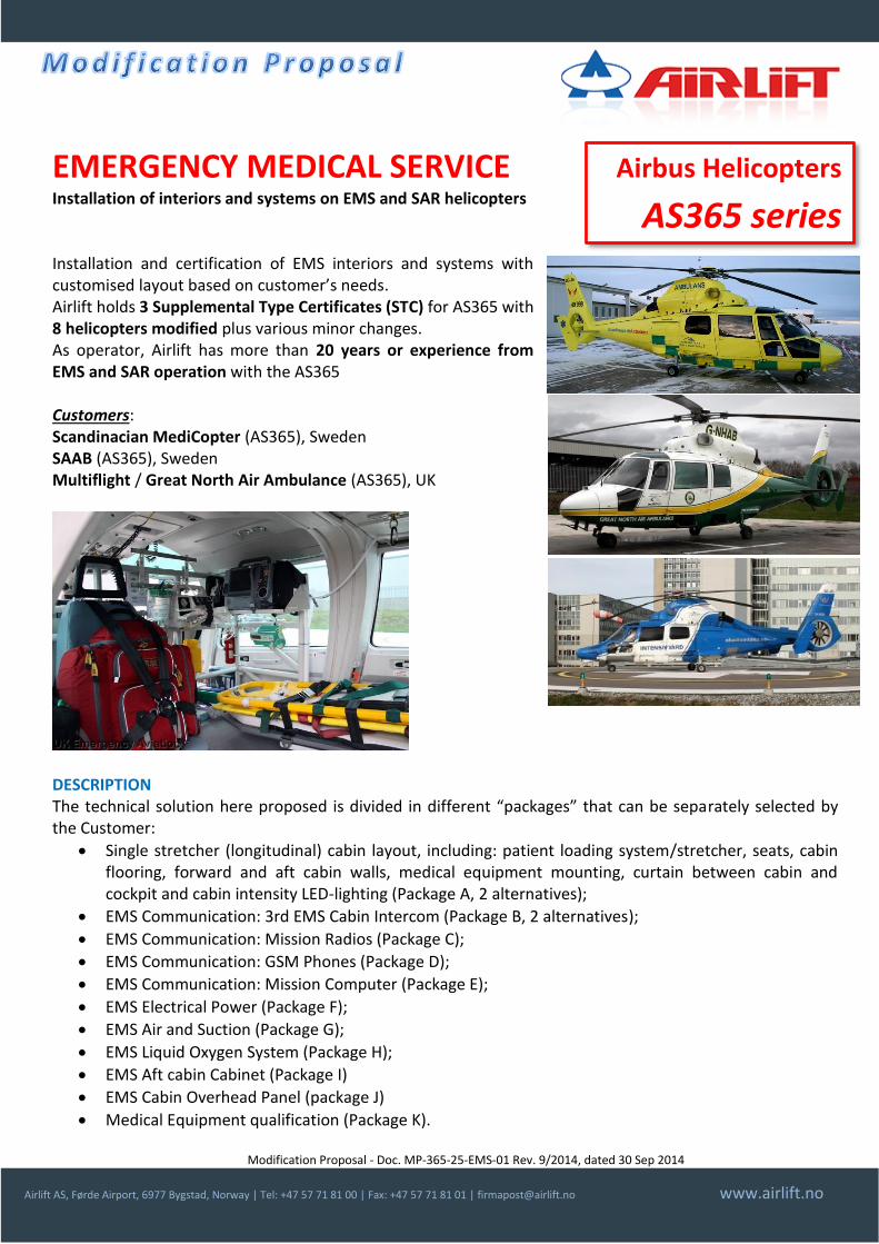
EMERGENCY MEDICAL SERVICE Installation of interiors and systems on EMS and SAR helicopters Installation and certification of EMS interiors and systems with customised layout based on customer’s needs. Airlift holds 3 Supplemental Type Certificates (STC) for AS365 with 8 helicopters modified plus various minor changes. As operator, Airlift has more than 20 years or experience from EMS and SAR operation with the AS365 Customers: Scandinacian MediCopter (AS365), Sweden SAAB (AS365), Sweden Multiflight / Great North Air Ambulance (AS365), UK
DESCRIPTION The technical solution here proposed is divided in different “packages” that can be separately selected by the Customer:
Single stretcher (longitudinal) cabin layout, including: patient loading system/stretcher, seats, cabin flooring, forward and aft cabin walls, medical equipment mounting, curtain between cabin and cockpit and cabin intensity LED-lighting (Package A, 2 alternatives);
EMS Communication: 3rd EMS Cabin Intercom (Package B, 2 alternatives);
EMS Communication: Mission Radios (Package C);
EMS Communication: GSM Phones (Package D);
EMS Communication: Mission Computer (Package E);
EMS Electrical Power (Package F);
EMS Air and Suction (Package G);
EMS Liquid Oxygen System (Package H);
EMS Aft cabin Cabinet (Package I)
EMS Cabin Overhead Panel (package J)
Medical Equipment qualification (Package K).
Airbus Helicopters
AS365 series
Modification Proposal - Doc. MP-365-25-EMS-01 Rev. 9/2014, dated 30 Sep 2014
Airlift AS, Førde Airport, 6977 Bygstad, Norway | Tel: +47 57 71 81 00 | Fax: +47 57 71 81 01 | [email protected] www.airlift.no
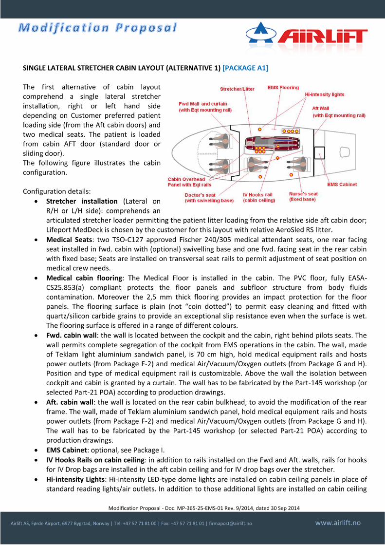
SINGLE LATERAL STRETCHER CABIN LAYOUT (ALTERNATIVE 1) [PACKAGE A1] The first alternative of cabin layout comprehend a single lateral stretcher installation, right or left hand side depending on Customer preferred patient loading side (from the Aft cabin doors) and two medical seats. The patient is loaded from cabin AFT door (standard door or sliding door). The following figure illustrates the cabin configuration. Configuration details:
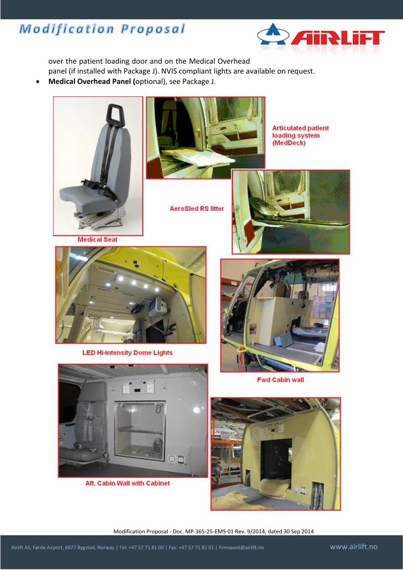
Stretcher installation (Lateral on R/H or L/H side): comprehends an articulated stretcher loader permitting the patient litter loading from the relative side aft cabin door; Lifeport MedDeck is chosen by the customer for this layout with relative AeroSled RS litter.
Medical Seats: two TSO-C127 approved Fischer 240/305 medical attendant seats, one rear facing seat installed in fwd. cabin with (optional) swivelling base and one fwd. facing seat in the rear cabin with fixed base; Seats are installed on transversal seat rails to permit adjustment of seat position on medical crew needs.
Medical cabin flooring: The Medical Floor is installed in the cabin. The PVC floor, fully EASA-CS25.853(a) compliant protects the floor panels and subfloor structure from body fluids contamination. Moreover the 2,5 mm thick flooring provides an impact protection for the floor panels. The flooring surface is plain (not “coin dotted”) to permit easy cleaning and fitted with quartz/silicon carbide grains to provide an exceptional slip resistance even when the surface is wet. The flooring surface is offered in a range of different colours.
Fwd. cabin wall: the wall is located between the cockpit and the cabin, right behind pilots seats. The wall permits complete segregation of the cockpit from EMS operations in the cabin. The wall, made of Teklam light aluminium sandwich panel, is 70 cm high, hold medical equipment rails and hosts power outlets (from Package F-2) and medical Air/Vacuum/Oxygen outlets (from Package G and H). Position and type of medical equipment rail is customizable. Above the wall the isolation between cockpit and cabin is granted by a curtain. The wall has to be fabricated by the Part-145 workshop (or selected Part-21 POA) according to production drawings.
Aft. cabin wall: the wall is located on the rear cabin bulkhead, to avoid the modification of the rear frame. The wall, made of Teklam aluminium sandwich panel, hold medical equipment rails and hosts power outlets (from Package F-2) and medical Air/Vacuum/Oxygen outlets (from Package G and H). The wall has to be fabricated by the Part-145 workshop (or selected Part-21 POA) according to production drawings.
EMS Cabinet: optional, see Package I.
IV Hooks Rails on cabin ceiling: in addition to rails installed on the Fwd and Aft. walls, rails for hooks for IV Drop bags are installed in the aft cabin ceiling and for IV drop bags over the stretcher.
Hi-intensity Lights: Hi-intensity LED-type dome lights are installed on cabin ceiling panels in place of standard reading lights/air outlets. In addition to those additional lights are installed on cabin ceiling
Modification Proposal - Doc. MP-365-25-EMS-01 Rev. 9/2014, dated 30 Sep 2014
Airlift AS, Førde Airport, 6977 Bygstad, Norway | Tel: +47 57 71 81 00 | Fax: +47 57 71 81 01 | [email protected] www.airlift.no
over the patient loading door and on the Medical Overhead panel (if installed with Package J). NVIS compliant lights are available on request.
Medical Overhead Panel (optional), see Package J.
Modification Proposal - Doc. MP-365-25-EMS-01 Rev. 9/2014, dated 30 Sep 2014
Airlift AS, Førde Airport, 6977 Bygstad, Norway | Tel: +47 57 71 81 00 | Fax: +47 57 71 81 01 | [email protected] www.airlift.no
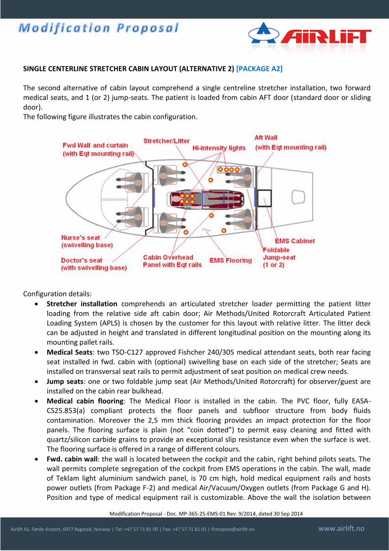
SINGLE CENTERLINE STRETCHER CABIN LAYOUT (ALTERNATIVE 2) [PACKAGE A2] The second alternative of cabin layout comprehend a single centreline stretcher installation, two forward medical seats, and 1 (or 2) jump-seats. The patient is loaded from cabin AFT door (standard door or sliding door). The following figure illustrates the cabin configuration.
Configuration details:
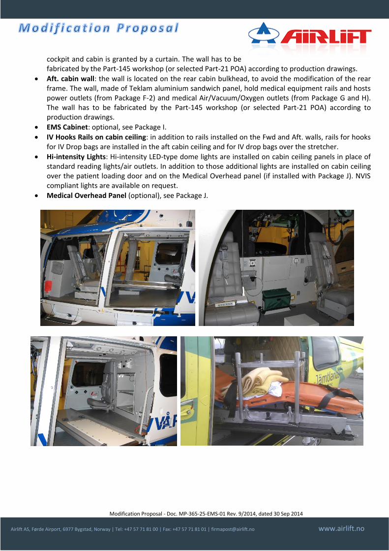
Stretcher installation comprehends an articulated stretcher loader permitting the patient litter loading from the relative side aft cabin door; Air Methods/United Rotorcraft Articulated Patient Loading System (APLS) is chosen by the customer for this layout with relative litter. The litter deck can be adjusted in height and translated in different longitudinal position on the mounting along its mounting pallet rails.
Medical Seats: two TSO-C127 approved Fishcher 240/305 medical attendant seats, both rear facing seat installed in fwd. cabin with (optional) swivelling base on each side of the stretcher; Seats are installed on transversal seat rails to permit adjustment of seat position on medical crew needs.
Jump seats: one or two foldable jump seat (Air Methods/United Rotorcraft) for observer/guest are installed on the cabin rear bulkhead.
Medical cabin flooring: The Medical Floor is installed in the cabin. The PVC floor, fully EASA-CS25.853(a) compliant protects the floor panels and subfloor structure from body fluids contamination. Moreover the 2,5 mm thick flooring provides an impact protection for the floor panels. The flooring surface is plain (not “coin dotted”) to permit easy cleaning and fitted with quartz/silicon carbide grains to provide an exceptional slip resistance even when the surface is wet. The flooring surface is offered in a range of different colours.
Fwd. cabin wall: the wall is located between the cockpit and the cabin, right behind pilots seats. The wall permits complete segregation of the cockpit from EMS operations in the cabin. The wall, made of Teklam light aluminium sandwich panel, is 70 cm high, hold medical equipment rails and hosts power outlets (from Package F-2) and medical Air/Vacuum/Oxygen outlets (from Package G and H). Position and type of medical equipment rail is customizable. Above the wall the isolation between
Modification Proposal - Doc. MP-365-25-EMS-01 Rev. 9/2014, dated 30 Sep 2014
Airlift AS, Førde Airport, 6977 Bygstad, Norway | Tel: +47 57 71 81 00 | Fax: +47 57 71 81 01 | [email protected] www.airlift.no
cockpit and cabin is granted by a curtain. The wall has to be fabricated by the Part-145 workshop (or selected Part-21 POA) according to production drawings.
Aft. cabin wall: the wall is located on the rear cabin bulkhead, to avoid the modification of the rear frame. The wall, made of Teklam aluminium sandwich panel, hold medical equipment rails and hosts power outlets (from Package F-2) and medical Air/Vacuum/Oxygen outlets (from Package G and H). The wall has to be fabricated by the Part-145 workshop (or selected Part-21 POA) according to production drawings.
EMS Cabinet: optional, see Package I.
IV Hooks Rails on cabin ceiling: in addition to rails installed on the Fwd and Aft. walls, rails for hooks for IV Drop bags are installed in the aft cabin ceiling and for IV drop bags over the stretcher.
Hi-intensity Lights: Hi-intensity LED-type dome lights are installed on cabin ceiling panels in place of standard reading lights/air outlets. In addition to those additional lights are installed on cabin ceiling over the patient loading door and on the Medical Overhead panel (if installed with Package J). NVIS compliant lights are available on request.
Medical Overhead Panel (optional), see Package J.
Modification Proposal - Doc. MP-365-25-EMS-01 Rev. 9/2014, dated 30 Sep 2014
Airlift AS, Førde Airport, 6977 Bygstad, Norway | Tel: +47 57 71 81 00 | Fax: +47 57 71 81 01 | [email protected] www.airlift.no
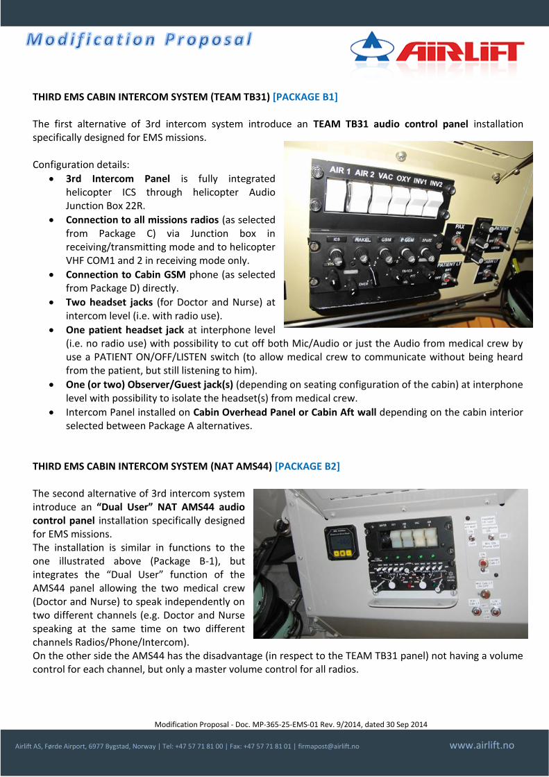
THIRD EMS CABIN INTERCOM SYSTEM (TEAM TB31) [PACKAGE B1] The first alternative of 3rd intercom system introduce an TEAM TB31 audio control panel installation specifically designed for EMS missions. Configuration details:
3rd Intercom Panel is fully integrated helicopter ICS through helicopter Audio Junction Box 22R.
Connection to all missions radios (as selected from Package C) via Junction box in receiving/transmitting mode and to helicopter VHF COM1 and 2 in receiving mode only.
Connection to Cabin GSM phone (as selected from Package D) directly.
Two headset jacks (for Doctor and Nurse) at intercom level (i.e. with radio use).
One patient headset jack at interphone level (i.e. no radio use) with possibility to cut off both Mic/Audio or just the Audio from medical crew by use a PATIENT ON/OFF/LISTEN switch (to allow medical crew to communicate without being heard from the patient, but still listening to him).
One (or two) Observer/Guest jack(s) (depending on seating configuration of the cabin) at interphone level with possibility to isolate the headset(s) from medical crew.
Intercom Panel installed on Cabin Overhead Panel or Cabin Aft wall depending on the cabin interior selected between Package A alternatives.
THIRD EMS CABIN INTERCOM SYSTEM (NAT AMS44) [PACKAGE B2] The second alternative of 3rd intercom system introduce an “Dual User” NAT AMS44 audio control panel installation specifically designed for EMS missions. The installation is similar in functions to the one illustrated above (Package B-1), but integrates the “Dual User” function of the AMS44 panel allowing the two medical crew (Doctor and Nurse) to speak independently on two different channels (e.g. Doctor and Nurse speaking at the same time on two different channels Radios/Phone/Intercom). On the other side the AMS44 has the disadvantage (in respect to the TEAM TB31 panel) not having a volume control for each channel, but only a master volume control for all radios.
Modification Proposal - Doc. MP-365-25-EMS-01 Rev. 9/2014, dated 30 Sep 2014
Airlift AS, Førde Airport, 6977 Bygstad, Norway | Tel: +47 57 71 81 00 | Fax: +47 57 71 81 01 | [email protected] www.airlift.no
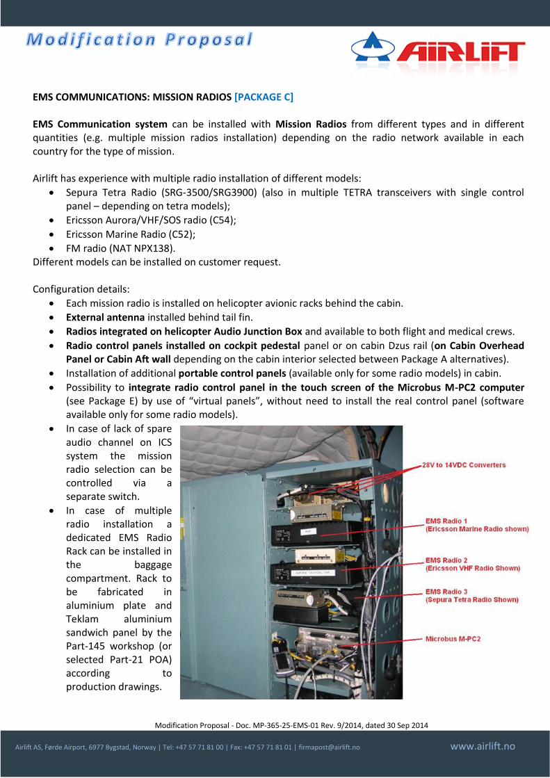
EMS COMMUNICATIONS: MISSION RADIOS [PACKAGE C] EMS Communication system can be installed with Mission Radios from different types and in different quantities (e.g. multiple mission radios installation) depending on the radio network available in each country for the type of mission. Airlift has experience with multiple radio installation of different models:
Sepura Tetra Radio (SRG-3500/SRG3900) (also in multiple TETRA transceivers with single control panel – depending on tetra models);
Ericsson Aurora/VHF/SOS radio (C54);
Ericsson Marine Radio (C52);
FM radio (NAT NPX138). Different models can be installed on customer request. Configuration details:
Each mission radio is installed on helicopter avionic racks behind the cabin.
External antenna installed behind tail fin.
Radios integrated on helicopter Audio Junction Box and available to both flight and medical crews.
Radio control panels installed on cockpit pedestal panel or on cabin Dzus rail (on Cabin Overhead Panel or Cabin Aft wall depending on the cabin interior selected between Package A alternatives).
Installation of additional portable control panels (available only for some radio models) in cabin.
Possibility to integrate radio control panel in the touch screen of the Microbus M-PC2 computer (see Package E) by use of “virtual panels”, without need to install the real control panel (software available only for some radio models).
In case of lack of spare audio channel on ICS system the mission radio selection can be controlled via a separate switch.
In case of multiple radio installation a dedicated EMS Radio Rack can be installed in the baggage compartment. Rack to be fabricated in aluminium plate and Teklam aluminium sandwich panel by the Part-145 workshop (or selected Part-21 POA) according to production drawings.
Modification Proposal - Doc. MP-365-25-EMS-01 Rev. 9/2014, dated 30 Sep 2014
Airlift AS, Førde Airport, 6977 Bygstad, Norway | Tel: +47 57 71 81 00 | Fax: +47 57 71 81 01 | [email protected] www.airlift.no
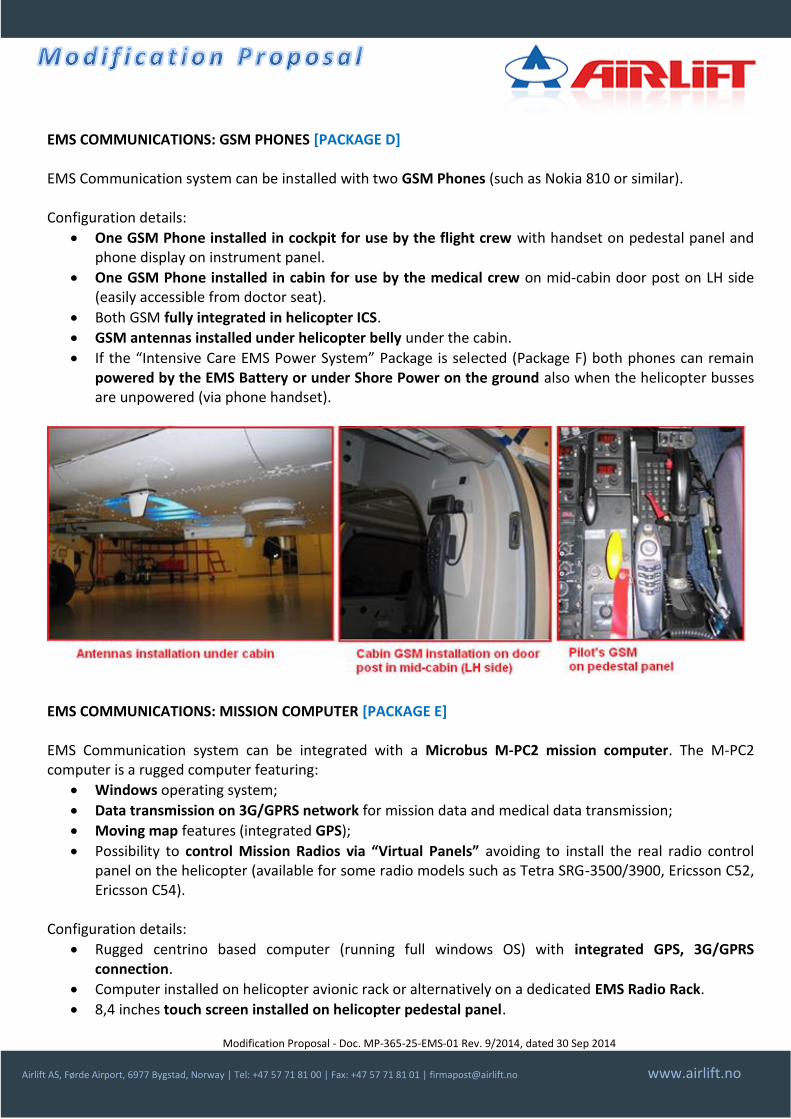
EMS COMMUNICATIONS: GSM PHONES [PACKAGE D] EMS Communication system can be installed with two GSM Phones (such as Nokia 810 or similar). Configuration details:
One GSM Phone installed in cockpit for use by the flight crew with handset on pedestal panel and phone display on instrument panel.
One GSM Phone installed in cabin for use by the medical crew on mid-cabin door post on LH side (easily accessible from doctor seat).
Both GSM fully integrated in helicopter ICS.
GSM antennas installed under helicopter belly under the cabin.
If the “Intensive Care EMS Power System” Package is selected (Package F) both phones can remain powered by the EMS Battery or under Shore Power on the ground also when the helicopter busses are unpowered (via phone handset).
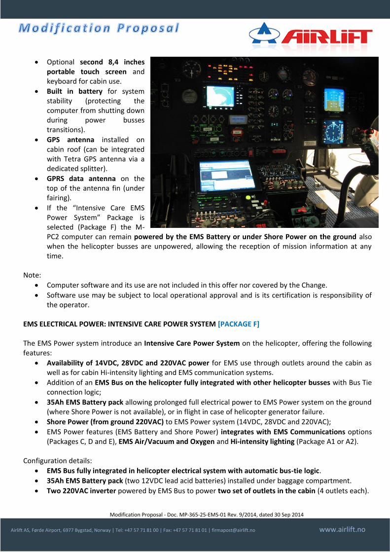
EMS COMMUNICATIONS: MISSION COMPUTER [PACKAGE E] EMS Communication system can be integrated with a Microbus M-PC2 mission computer. The M-PC2 computer is a rugged computer featuring:
Windows operating system;
Data transmission on 3G/GPRS network for mission data and medical data transmission;
Moving map features (integrated GPS);
Possibility to control Mission Radios via “Virtual Panels” avoiding to install the real radio control panel on the helicopter (available for some radio models such as Tetra SRG-3500/3900, Ericsson C52, Ericsson C54).
Configuration details:
Rugged centrino based computer (running full windows OS) with integrated GPS, 3G/GPRS connection.
Computer installed on helicopter avionic rack or alternatively on a dedicated EMS Radio Rack.
8,4 inches touch screen installed on helicopter pedestal panel.
Modification Proposal - Doc. MP-365-25-EMS-01 Rev. 9/2014, dated 30 Sep 2014
Airlift AS, Førde Airport, 6977 Bygstad, Norway | Tel: +47 57 71 81 00 | Fax: +47 57 71 81 01 | [email protected] www.airlift.no
Optional second 8,4 inches portable touch screen and keyboard for cabin use.
Built in battery for system stability (protecting the computer from shutting down during power busses transitions).
GPS antenna installed on cabin roof (can be integrated with Tetra GPS antenna via a dedicated splitter).
GPRS data antenna on the top of the antenna fin (under fairing).
If the “Intensive Care EMS Power System” Package is selected (Package F) the M-PC2 computer can remain powered by the EMS Battery or under Shore Power on the ground also when the helicopter busses are unpowered, allowing the reception of mission information at any time.
Note:
Computer software and its use are not included in this offer nor covered by the Change.
Software use may be subject to local operational approval and is its certification is responsibility of the operator.
EMS ELECTRICAL POWER: INTENSIVE CARE POWER SYSTEM [PACKAGE F] The EMS Power system introduce an Intensive Care Power System on the helicopter, offering the following features:
Availability of 14VDC, 28VDC and 220VAC power for EMS use through outlets around the cabin as well as for cabin Hi-intensity lighting and EMS communication systems.
Addition of an EMS Bus on the helicopter fully integrated with other helicopter busses with Bus Tie connection logic;
35Ah EMS Battery pack allowing prolonged full electrical power to EMS Power system on the ground (where Shore Power is not available), or in flight in case of helicopter generator failure.
Shore Power (from ground 220VAC) to EMS Power system (14VDC, 28VDC and 220VAC);
EMS Power features (EMS Battery and Shore Power) integrates with EMS Communications options (Packages C, D and E), EMS Air/Vacuum and Oxygen and Hi-intensity lighting (Package A1 or A2).
Configuration details:
EMS Bus fully integrated in helicopter electrical system with automatic bus-tie logic.
35Ah EMS Battery pack (two 12VDC lead acid batteries) installed under baggage compartment.
Two 220VAC inverter powered by EMS Bus to power two set of outlets in the cabin (4 outlets each).

Modification Proposal - Doc. MP-365-25-EMS-01 Rev. 9/2014, dated 30 Sep 2014
Airlift AS, Førde Airport, 6977 Bygstad, Norway | Tel: +47 57 71 81 00 | Fax: +47 57 71 81 01 | [email protected] www.airlift.no
Two/three 14VDC converters to power dual 14/28VDC outlets (6 ea.), as well as 12VDC communication systems (radios, computer, GSM phones).
Shore Power intake (located next to helicopter Ground power inlet) permits to power the full EMS Power system from ground 220VAC standard power.
EMS Battery charger, driven from one 220VAC inverter in flight and from Shore power on the ground to maintain EMS Battery fully charged (located under baggage compartment).
14VDC and 28VDC converters (powered from 220VDC shore power) to run 28VDC and 14 VDC EMS systems (outlets, communication, Lighting) on the ground while helicopter busses are unpowered giving unlimited autonomy to the medical crew on the ground.
All brackets/shelf to be fabricated in aluminium plate and Teklam aluminium sandwich panel by the Part-145 workshop (or selected Part-21 POA) according to production drawings
EMS Power Battery Pack (35Ah), Ground power converters (14/28VDC) – 220VAC Inverters.
Aft Wall power outlets – EMS Radio Rack/Power distribution in Baggage Compartment.
Modification Proposal - Doc. MP-365-25-EMS-01 Rev. 9/2014, dated 30 Sep 2014
Airlift AS, Førde Airport, 6977 Bygstad, Norway | Tel: +47 57 71 81 00 | Fax: +47 57 71 81 01 | [email protected] www.airlift.no
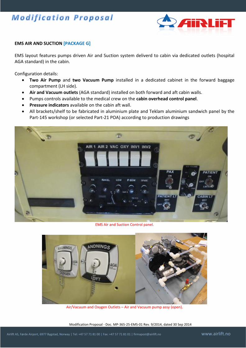
EMS AIR AND SUCTION [PACKAGE G] EMS layout features pumps driven Air and Suction system deliverd to cabin via dedicated outlets (hospital AGA standard) in the cabin. Configuration details:
Two Air Pump and two Vacuum Pump installed in a dedicated cabinet in the forward baggage compartment (LH side).
Air and Vacuum outlets (AGA standard) installed on both forward and aft cabin walls.
Pumps controls available to the medical crew on the cabin overhead control panel.
Pressure indicators available on the cabin aft wall.
All brackets/shelf to be fabricated in aluminium plate and Teklam aluminium sandwich panel by the Part-145 workshop (or selected Part-21 POA) according to production drawings
EMS Air and Suction Control panel.
Air/Vacuum and Oxygen Outlets – Air and Vacuum pump assy (open).

Modification Proposal - Doc. MP-365-25-EMS-01 Rev. 9/2014, dated 30 Sep 2014
Airlift AS, Førde Airport, 6977 Bygstad, Norway | Tel: +47 57 71 81 00 | Fax: +47 57 71 81 01 | [email protected] www.airlift.no
EMS LIQUID OXYGEN SYSTEM [PACKAGE H] EMS Oxygen is provided by a Liquid Oxygen Unit and distributed through the cabin via dedicated outlets (hospital AGA standard) Configuration details:
10 liter Liquid Oxygen system providing 8000 liters of gaseous oxygen.
Oxygen outlets (AGA standard) installed on both forward and aft cabin walls.
Quantity indicator available on the cabin aft wall.
EMS Liquid Oxygen System unit (open). – cabin Air/Vacuum and Oxygen pressure and quantity indicators
EMS AFT WALL CABINET [PACKAGE I] Aft Cabinet located in the tunnel between cabin and baggage compartment to provide storage capacity for EMS equipment/materials. Unlike the first alternative this cabinet has to be fabricated in aluminium plate and Teklam aluminium sandwich panel by the Part-145 workshop (or selected Part-21 POA) according to production drawings. Interior can be customised according to customer request. a cargo net secure the content of the cabinet from falling out.
Modification Proposal - Doc. MP-365-25-EMS-01 Rev. 9/2014, dated 30 Sep 2014
Airlift AS, Førde Airport, 6977 Bygstad, Norway | Tel: +47 57 71 81 00 | Fax: +47 57 71 81 01 | [email protected] www.airlift.no
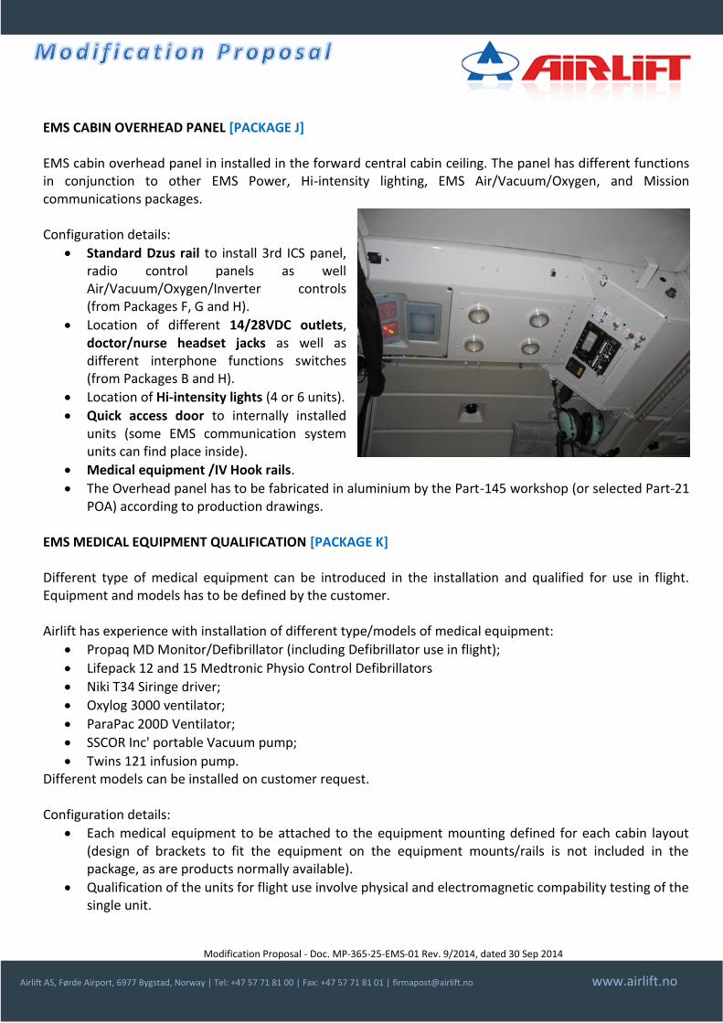
EMS CABIN OVERHEAD PANEL [PACKAGE J] EMS cabin overhead panel in installed in the forward central cabin ceiling. The panel has different functions in conjunction to other EMS Power, Hi-intensity lighting, EMS Air/Vacuum/Oxygen, and Mission communications packages. Configuration details:
Standard Dzus rail to install 3rd ICS panel, radio control panels as well Air/Vacuum/Oxygen/Inverter controls (from Packages F, G and H).
Location of different 14/28VDC outlets, doctor/nurse headset jacks as well as different interphone functions switches (from Packages B and H).
Location of Hi-intensity lights (4 or 6 units).
Quick access door to internally installed units (some EMS communication system units can find place inside).
Medical equipment /IV Hook rails.
The Overhead panel has to be fabricated in aluminium by the Part-145 workshop (or selected Part-21 POA) according to production drawings.
EMS MEDICAL EQUIPMENT QUALIFICATION [PACKAGE K] Different type of medical equipment can be introduced in the installation and qualified for use in flight. Equipment and models has to be defined by the customer. Airlift has experience with installation of different type/models of medical equipment:
Propaq MD Monitor/Defibrillator (including Defibrillator use in flight);
Lifepack 12 and 15 Medtronic Physio Control Defibrillators
Niki T34 Siringe driver;
Oxylog 3000 ventilator;
ParaPac 200D Ventilator;
SSCOR Inc' portable Vacuum pump;
Twins 121 infusion pump. Different models can be installed on customer request. Configuration details:
Each medical equipment to be attached to the equipment mounting defined for each cabin layout (design of brackets to fit the equipment on the equipment mounts/rails is not included in the package, as are products normally available).
Qualification of the units for flight use involve physical and electromagnetic compability testing of the single unit.

Modification Proposal - Doc. MP-365-25-EMS-01 Rev. 9/2014, dated 30 Sep 2014
Airlift AS, Førde Airport, 6977 Bygstad, Norway | Tel: +47 57 71 81 00 | Fax: +47 57 71 81 01 | [email protected] www.airlift.no
CONDITIONS & COMPATIBILITY LIMITATIONS PLEASE NOTE THAT THIS PROPOSAL IS INTENDED DESCRIPTION ONLY! This presentation has been prepared using different EMS modification certified by Airlift (3 STC and different minor changes). Each installation could need modification from the configuration here described, due to differences between AS365 series or due to availability of components. Compatibility with each helicopter configuration and with installation already in place to be evaluated. DOCUMENTATION DELIVERED Approval Form, installation instructions, material list, drawings, wiring diagrams, instructions for continued airworthiness, rotorcraft flight manual supplement. KIT All parts shall be ordered separately at vendors indicated in the material list. APPROVAL Approval STC Number Type/Model Notes
EASA 10017102 AS365 C,C1,C2,C3,N,N1,N2,N3
EASA 10017289 AS365 N3
EASA 10029680 AS365 N,N1,N2,N3
Airlift AS is an EASA Part-21 Subp. J Approved Design Organisation (Approval No. EASA.21J.315). CONTACT INFORMATION For order placement or request of information contact Airlift AS Design Organisation at +47 57 71 81 00 or via email at [email protected] or visit our website www.airlift-doa.com.
For a complete catalogue of our EASA Part-21 Approved Changes visit: www.airlift-doa.com
Modification Proposal - Doc. MP-350-23-101-01 Rev. 1/2013, dated 01 Jul 2013
Airlift AS, Førde Airport, 6977 Bygstad, Norway | Tel: +47 57 71 81 00 | Fax: +47 57 71 81 01 | [email protected] www.airlift.no
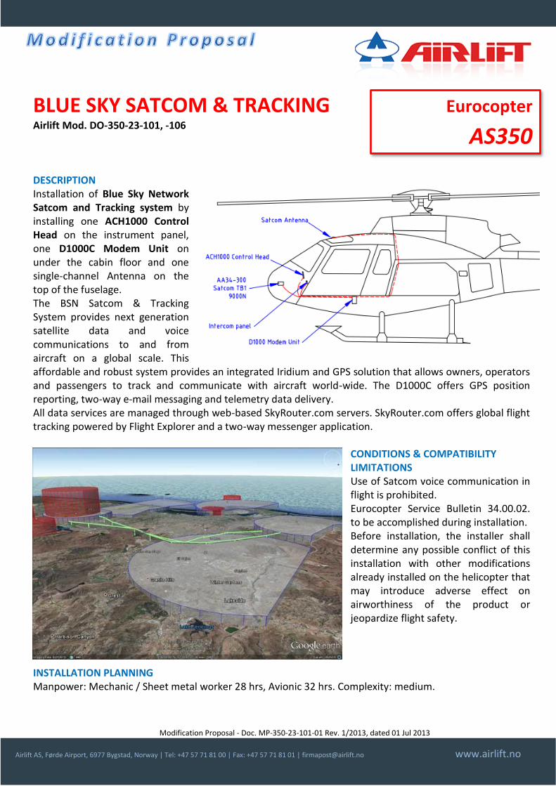
BLUE SKY SATCOM & TRACKING Airlift Mod. DO-350-23-101, -106 DESCRIPTION Installation of Blue Sky Network Satcom and Tracking system by installing one ACH1000 Control Head on the instrument panel, one D1000C Modem Unit on under the cabin floor and one single-channel Antenna on the top of the fuselage. The BSN Satcom & Tracking System provides next generation satellite data and voice communications to and from aircraft on a global scale. This affordable and robust system provides an integrated Iridium and GPS solution that allows owners, operators and passengers to track and communicate with aircraft world-wide. The D1000C offers GPS position reporting, two-way e-mail messaging and telemetry data delivery. All data services are managed through web-based SkyRouter.com servers. SkyRouter.com offers global flight tracking powered by Flight Explorer and a two-way messenger application.
CONDITIONS & COMPATIBILITY LIMITATIONS Use of Satcom voice communication in flight is prohibited. Eurocopter Service Bulletin 34.00.02. to be accomplished during installation. Before installation, the installer shall determine any possible conflict of this installation with other modifications already installed on the helicopter that may introduce adverse effect on airworthiness of the product or jeopardize flight safety.
INSTALLATION PLANNING Manpower: Mechanic / Sheet metal worker 28 hrs, Avionic 32 hrs. Complexity: medium.
Eurocopter
AS350
Modification Proposal - Doc. MP-350-23-101-01 Rev. 1/2013, dated 01 Jul 2013
Airlift AS, Førde Airport, 6977 Bygstad, Norway | Tel: +47 57 71 81 00 | Fax: +47 57 71 81 01 | [email protected] www.airlift.no
DOCUMENTRATION DELIVERED Approval Form, installation instructions, material list, drawings, wiring diagrams, instructions for continued airworthiness, rotorcraft flight manual supplement. KIT No kit is associated to this modification. All parts shall be ordered separately at vendors indicated in the material list. Main units are available from Blue Sky Network official dealers (www.blueskynetwork.com). APPROVAL Approval STC Number Type/Model Notes
EASA Minor change AS350 B2 and B3
Other AS350/EC130 series helicopters are also available on request! Airlift AS is an EASA Part-21 Subp. J Approved Design Organisation (Approval No. EASA.21J.315). PRICE (2013) Description Price range (*)
Installation documentation and Approval Contact us
Delivery time for document package: 2/3 weeks Price does NOT include Iridium phone activation nor the SkyRouter tracking use license. (*) Prices or price ranges indicated is indicative and depends on the actual configuration of the helicopter. Indicated prices are ex works and excludes VAT, packaging and transport. Prices valid at the date of issue of this document. CONTACT INFORMATION For order placement or request of information contact Airlift AS Design Organisation at +47 57 71 81 00 or via email at [email protected] or visit our website www.airlift-doa.com.
For a complete catalogue of our EASA Part-21 Approved Changes visit: www.airlift-doa.com
Modification Proposal - Doc. MP-350-23-110-01 Rev. 1/2013, dated 01 Jul 2013
Airlift AS, Førde Airport, 6977 Bygstad, Norway | Tel: +47 57 71 81 00 | Fax: +47 57 71 81 01 | [email protected] www.airlift.no
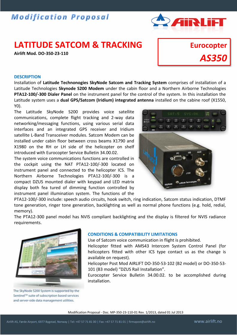
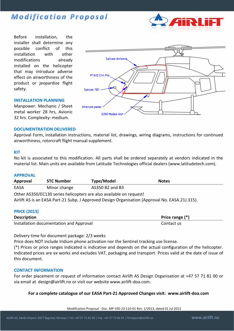
LATITUDE SATCOM & TRACKING Airlift Mod. DO-350-23-110 DESCRIPTION Installation of Latitude Technonogies SkyNode Satcom and Tracking System comprises of installation of a Latitude Technologies Skynode S200 Modem under the cabin floor and a Northern Airborne Technologies PTA12-100/-300 Dialer Panel on the instrument panel for the control of the system. In this installation the Latitude system uses a dual GPS/Satcom (Iridium) integrated antenna installed on the cabine roof (X1550, Y0). The Latitude SkyNode S200 provides voice satellite communications, complete flight tracking and 2-way data networking/messaging functions, using various serial data interfaces and an integrated GPS receiver and Iridium satellite L-Band Transceiver modules. Satcom Modem can be installed under cabin floor between cross beams X1790 and X1980 on the RH or LH side of the helicopter on shelf introduced with Eurocopter Service Bulletin 34.00.02. The system voice communications functions are controlled in the cockpit using the NAT PTA12-100/-300 located on instrument panel and connected to the helicopter ICS. The Northern Airborne Technologies PTA12-100/-300 is a compact DZUS mounted dialer with keypad and LED matrix display both fea tured of dimming function controlled by instrument panel illumination system. The functions of the PTA12-100/-300 include: speech audio circuits, hook switch, ring indication, Satcom status indication, DTMF tone generation, ringer tone generation, backlighting as well as normal phone functions (e.g. hold, redial, memory). The PTA12-300 panel model has NVIS compliant backlighting and the display is filtered for NVIS radiance requirements.
CONDITIONS & COMPATIBILITY LIMITATIONS Use of Satcom voice communication in flight is prohibited. Helicopter fitted with AMS43 Intercom System Control Panel (for helicopters fitted with other ICS type contact us as the change is available on request). Helicopter Post Mod AIRLIFT DO-350-53-102 (B2 model) or DO-350-53-101 (B3 model) “DZUS Rail Installation”. Eurocopter Service Bulletin 34.00.02. to be accomplished during installation.
Eurocopter
AS350
Modification Proposal - Doc. MP-350-23-110-01 Rev. 1/2013, dated 01 Jul 2013
Airlift AS, Førde Airport, 6977 Bygstad, Norway | Tel: +47 57 71 81 00 | Fax: +47 57 71 81 01 | [email protected] www.airlift.no
Before installation, the installer shall determine any possible conflict of this installation with other modifications already installed on the helicopter that may introduce adverse effect on airworthiness of the product or jeopardize flight safety. INSTALLATION PLANNING Manpower: Mechanic / Sheet metal worker 28 hrs, Avionic 32 hrs. Complexity: medium. DOCUMENTRATION DELIVERED Approval Form, installation instructions, material list, drawings, wiring diagrams, instructions for continued airworthiness, rotorcraft flight manual supplement. KIT No kit is associated to this modification. All parts shall be ordered separately at vendors indicated in the material list. Main units are available from Latitude Technologies official dealers (www.latitudetech.com). APPROVAL Approval STC Number Type/Model Notes
EASA Minor change AS350 B2 and B3
Other AS350/EC130 series helicopters are also available on request! Airlift AS is an EASA Part-21 Subp. J Approved Design Organisation (Approval No. EASA.21J.315). PRICE (2013) Description Price range (*)
Installation documentation and Approval Contact us
Delivery time for document package: 2/3 weeks Price does NOT include Iridium phone activation nor the Sentinel tracking use license. (*) Prices or price ranges indicated is indicative and depends on the actual configuration of the helicopter. Indicated prices are ex works and excludes VAT, packaging and transport. Prices valid at the date of issue of this document. CONTACT INFORMATION For order placement or request of information contact Airlift AS Design Organisation at +47 57 71 81 00 or via email at [email protected] or visit our website www.airlift-doa.com.
For a complete catalogue of our EASA Part-21 Approved Changes visit: www.airlift-doa.com
Modification Proposal - Doc. MP-350-24-101 Rev. 9/2014, dated 01 September 2014
Airlift AS, Førde Airport, 6977 Bygstad, Norway | Tel: +47 57 71 81 00 | Fax: +47 57 71 81 01 | [email protected] www.airlift.no
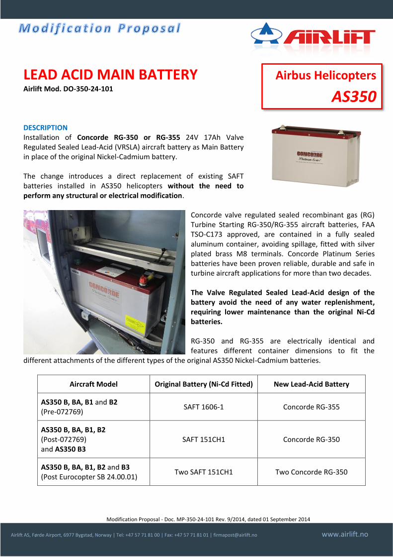
LEAD ACID MAIN BATTERY Airlift Mod. DO-350-24-101 DESCRIPTION Installation of Concorde RG-350 or RG-355 24V 17Ah Valve Regulated Sealed Lead-Acid (VRSLA) aircraft battery as Main Battery in place of the original Nickel-Cadmium battery. The change introduces a direct replacement of existing SAFT batteries installed in AS350 helicopters without the need to perform any structural or electrical modification.
Concorde valve regulated sealed recombinant gas (RG) Turbine Starting RG-350/RG-355 aircraft batteries, FAA TSO-C173 approved, are contained in a fully sealed aluminum container, avoiding spillage, fitted with silver plated brass M8 terminals. Concorde Platinum Series batteries have been proven reliable, durable and safe in turbine aircraft applications for more than two decades.
The Valve Regulated Sealed Lead-Acid design of the battery avoid the need of any water replenishment, requiring lower maintenance than the original Ni-Cd batteries.
RG-350 and RG-355 are electrically identical and features different container dimensions to fit the
different attachments of the different types of the original AS350 Nickel-Cadmium batteries.
Aircraft Model Original Battery (Ni-Cd Fitted) New Lead-Acid Battery
AS350 B, BA, B1 and B2 (Pre-072769)
SAFT 1606-1 Concorde RG-355
AS350 B, BA, B1, B2 (Post-072769) and AS350 B3
SAFT 151CH1 Concorde RG-350
AS350 B, BA, B1, B2 and B3 (Post Eurocopter SB 24.00.01)
Two SAFT 151CH1 Two Concorde RG-350
Airbus Helicopters
AS350

Modification Proposal - Doc. MP-350-24-101 Rev. 9/2014, dated 01 September 2014
Airlift AS, Førde Airport, 6977 Bygstad, Norway | Tel: +47 57 71 81 00 | Fax: +47 57 71 81 01 | [email protected] www.airlift.no
CONDITIONS & COMPATIBILITY LIMITATIONS Before installation, the installer shall determine any possible conflict of this installation with other modifications already installed on the helicopter that may introduce adverse effect on airworthiness of the product or jeopardize flight safety. INSTALLATION PLANNING Manpower: Avionic technician, 2 hours. Complexity: low. DOCUMENTRATION DELIVERED Approval Form, installation instructions, material list, instructions for continued airworthiness, rotorcraft flight manual supplement can be found at: http://www.airlift-doa.com/lead-acid-main-battery or type this shortened URL on your browser: http://goo.gl/qL6xj7 or scan the QR-code shown. KIT One or two Concorde RG-350 or RG-355 24V 17Ah Valve Regulated Sealed Lead-Acid (VRSLA) aircraft battery. Concorde’s Battery charger/Capacity tester BC-8000 is also available separately. APPROVAL Approval STC Number Type/Model Notes
EASA 10044362 AS350 B, BA, B1, B2 and B3.
Canada (TC) Acceptance of EASA STC
AS350 B, BA, B1, B2 and B3. Ref. NAHI 5010-13-0117
Brasil CST 2013S11-07 AS350 B, BA, B1, B2 and B3.
Airlift is an EASA Part-21 Subp. J Approved Design Organisation (Approval No. EASA.21J.315). PRICE (2013) Description Price
Installation documentation and Approval (*)
Kit: RG-350 or RG-355 battery (*)
Tool: Battery charger/Capacity tester BC-8000 (*)
Delivery time: (*) (*): Contact Concorde’s Worldwide Distribution Network (web: www.concordebattery.com). CONTACT INFORMATION For request of information contact Airlift Design Organisation at +47 57 71 81 00 or via email at [email protected] or visit our website www.airlift-doa.com. For order placement contact Concorde’s Worldwide Distribution Network (www.concordebattery.com).
For a complete catalogue of our EASA Part-21 Approved Changes visit: www.airlift-doa.com
Modification Proposal - Doc. MP-350-25-102-01 Rev. 1/2013, dated 01 Jul 2013
Airlift AS, Førde Airport, 6977 Bygstad, Norway | Tel: +47 57 71 81 00 | Fax: +47 57 71 81 01 | [email protected] www.airlift.no
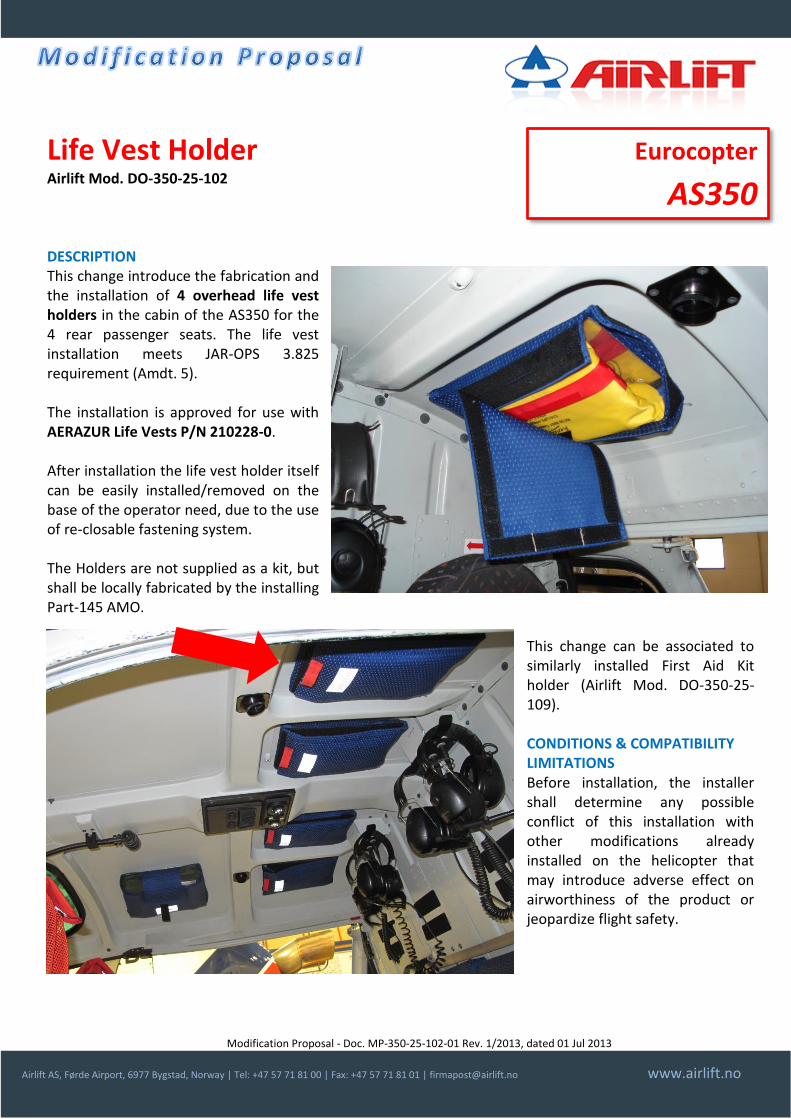
Life Vest Holder Airlift Mod. DO-350-25-102 DESCRIPTION This change introduce the fabrication and the installation of 4 overhead life vest holders in the cabin of the AS350 for the 4 rear passenger seats. The life vest installation meets JAR-OPS 3.825 requirement (Amdt. 5). The installation is approved for use with AERAZUR Life Vests P/N 210228-0. After installation the life vest holder itself can be easily installed/removed on the base of the operator need, due to the use of re-closable fastening system. The Holders are not supplied as a kit, but shall be locally fabricated by the installing Part-145 AMO.
This change can be associated to similarly installed First Aid Kit holder (Airlift Mod. DO-350-25-109).
CONDITIONS & COMPATIBILITY LIMITATIONS Before installation, the installer shall determine any possible conflict of this installation with other modifications already installed on the helicopter that may introduce adverse effect on airworthiness of the product or jeopardize flight safety.
Eurocopter
AS350

Modification Proposal - Doc. MP-350-25-102-01 Rev. 1/2013, dated 01 Jul 2013
Airlift AS, Førde Airport, 6977 Bygstad, Norway | Tel: +47 57 71 81 00 | Fax: +47 57 71 81 01 | [email protected] www.airlift.no
INSTALLATION PLANNING Manpower: Avionic technician: 2 hours. Complexity: Low. DOCUMENTRATION DELIVERED Approval Form, installation instructions, material list, drawings, and instructions for continued airworthiness. KIT No kit is associated to this modification. All parts shall be ordered separately at vendors indicated in the material list. APPROVAL Approval STC Number Type/Model Notes
EASA Minor change AS350 series
Airlift AS is an EASA Part-21 Subp. J Approved Design Organisation (Approval No. EASA.21J.315). PRICE (2013) Description Price range (*)
Installation documentation and Approval Contact us
Delivery time for document package: 2/3 weeks (*) Prices or price ranges indicated is indicative and depends on the actual configuration of the helicopter. Indicated prices are ex works and excludes VAT, packaging and transport. Prices valid at the date of issue of this document. CONTACT INFORMATION For order placement or request of information contact Airlift AS Design Organisation at +47 57 71 81 00 or via email at [email protected] or visit our website www.airlift-doa.com.
For a complete catalogue of our EASA Part-21 Approved Changes visit: www.airlift-doa.com
Modification Proposal - Doc. MP-350-25-107-01 Rev. 1/2013, dated 01 Jul 2013
Airlift AS, Førde Airport, 6977 Bygstad, Norway | Tel: +47 57 71 81 00 | Fax: +47 57 71 81 01 | [email protected] www.airlift.no
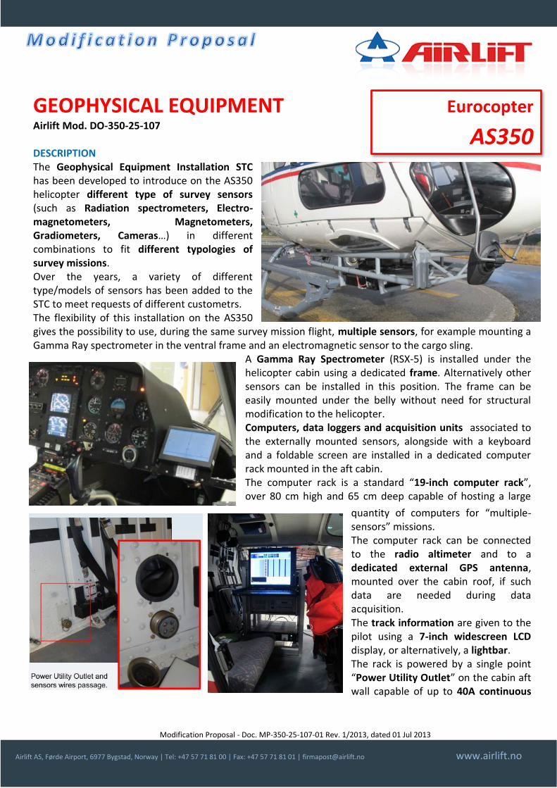
GEOPHYSICAL EQUIPMENT Airlift Mod. DO-350-25-107 DESCRIPTION The Geophysical Equipment Installation STC has been developed to introduce on the AS350 helicopter different type of survey sensors (such as Radiation spectrometers, Electro-magnetometers, Magnetometers, Gradiometers, Cameras…) in different combinations to fit different typologies of survey missions. Over the years, a variety of different type/models of sensors has been added to the STC to meet requests of different custometrs. The flexibility of this installation on the AS350 gives the possibility to use, during the same survey mission flight, multiple sensors, for example mounting a Gamma Ray spectrometer in the ventral frame and an electromagnetic sensor to the cargo sling.
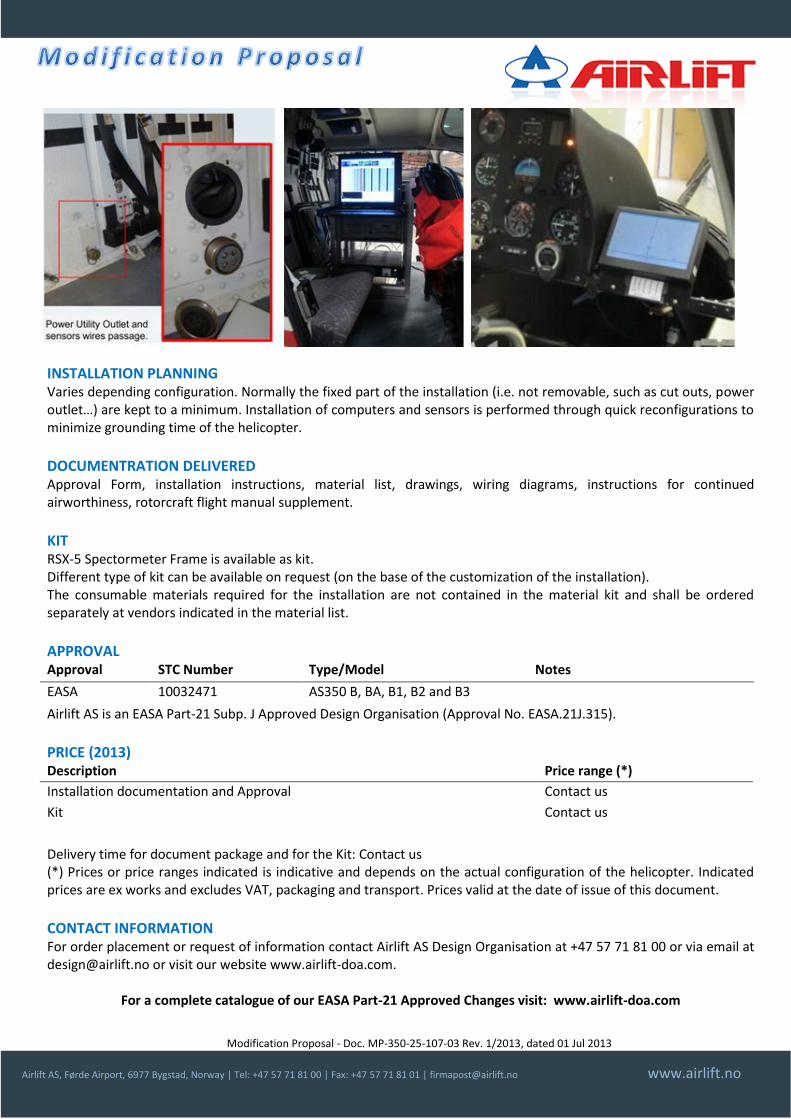
A Gamma Ray Spectrometer (RSX-5) is installed under the helicopter cabin using a dedicated frame. Alternatively other sensors can be installed in this position. The frame can be easily mounted under the belly without need for structural modification to the helicopter. Computers, data loggers and acquisition units associated to the externally mounted sensors, alongside with a keyboard and a foldable screen are installed in a dedicated computer rack mounted in the aft cabin. The computer rack is a standard “19-inch computer rack”, over 80 cm high and 65 cm deep capable of hosting a large
quantity of computers for “multiple-sensors” missions. The computer rack can be connected to the radio altimeter and to a dedicated external GPS antenna, mounted over the cabin roof, if such data are needed during data acquisition. The track information are given to the pilot using a 7-inch widescreen LCD display, or alternatively, a lightbar. The rack is powered by a single point “Power Utility Outlet” on the cabin aft wall capable of up to 40A continuous
Eurocopter
AS350

Modification Proposal - Doc. MP-350-25-107-01 Rev. 1/2013, dated 01 Jul 2013
Airlift AS, Førde Airport, 6977 Bygstad, Norway | Tel: +47 57 71 81 00 | Fax: +47 57 71 81 01 | [email protected] www.airlift.no
load. The power is controlled via a dedicated on/off push button on the pilot’s console and status shown via a “Utility Power” indicator light on the instrument panel. CONDITIONS & COMPATIBILITY LIMITATIONS Before installation, the installer shall determine any possible conflict of this installation with other modifications already installed on the helicopter that may introduce adverse effect on airworthiness of the product or jeopardize flight safety.
INSTALLATION PLANNING Varies depending configuration. Normally the fixed part of the installation (i.e. not removable, such as cut outs, power outlet…) are kept to a minimum. Installation of computers and sensors is performed through quick reconfigurations to minimize grounding time of the helicopter.
DOCUMENTRATION DELIVERED Approval Form, installation instructions, material list, drawings, wiring diagrams, instructions for continued airworthiness, rotorcraft flight manual supplement.
KIT RSX-5 Spectormeter Frame is available as kit. Different type of kit can be available on request (on the base of the customization of the installation). The consumable materials required for the installation are not contained in the material kit and shall be ordered separately at vendors indicated in the material list.
APPROVAL Approval STC Number Type/Model Notes
EASA 10032471 AS350 B, BA, B1, B2 and B3
Airlift AS is an EASA Part-21 Subp. J Approved Design Organisation (Approval No. EASA.21J.315).
PRICE (2013) Description Price range (*)
Installation documentation and Approval Contact us
Kit Contact us
Delivery time for document package and for the Kit: Contact us (*) Prices or price ranges indicated is indicative and depends on the actual configuration of the helicopter. Indicated prices are ex works and excludes VAT, packaging and transport. Prices valid at the date of issue of this document.
CONTACT INFORMATION For order placement or request of information contact Airlift AS Design Organisation at +47 57 71 81 00 or via email at [email protected] or visit our website www.airlift-doa.com.
For a complete catalogue of our EASA Part-21 Approved Changes visit: www.airlift-doa.com

Modification Proposal - Doc. MP-350-25-107-02 Rev. 1/2013, dated 01 Jul 2013
Airlift AS, Førde Airport, 6977 Bygstad, Norway | Tel: +47 57 71 81 00 | Fax: +47 57 71 81 01 | [email protected] www.airlift.no
GEM GSMP-35A MAGNETOMETER Part of Airlift Mod. DO-350-25-107 DESCRIPTION The GEM System GSMP-35A “Three axial Gradiometer/Magnetoemter” is part of Airlift’s Geophysical Equipment Installation STC for the AS350 helicopter, for airborne geophysical exploration and geological mapping. The STC includes as well different type of survey sensors (such as Radiation spectrometers, Electro-magnetometers, Magnetometers, Gradiometers, Cameras…) in different combinations to fit different typologies of survey missions. Over the years, a variety of different type/models of sensors has been added to the STC to meet requests of different customers. The GSMP-35A magnetometer is a unique optically pumped Potassium sensor, high resolution Magnetometer, Vertical / Horizontal and Tri-Axial Gradiometer. The GSMP-35A gradiometer is attached under the helicopter cargo hook. The installation can be used with both cargo hook or the cargo swing. The use of the helicopter standard cargo hook installation instead of the cargo swing permits the installation of additional sensors under the helicopter belly, such as spectrometers or cameras. The flexibility of this installation on the AS350 gives the possibility to use, during the same survey mission flight, multiple sensors, for example mounting a Gamma Ray spectrometer in the ventral frame and an electromagnetic sensor to the cargo sling. Computers, data loggers and acquisition units associated to the externally mounted sensors, alongside with a keyboard and a foldable screen are installed in a dedicated computer rack mounted in the aft cabin. The track information are given to the pilot using a 7-inch widescreen LCD display, or alternatively, a lightbar. The rack is powered by a single point “Power Utility Outlet” on the cabin aft wall capable of up to 40A continuous load. The power is controlled via a dedicated on/off push button on the pilot’s console and status shown via a “Utility Power” indicator light on the instrument panel.
CONDITIONS & COMPATIBILITY LIMITATIONS Before installation, the installer shall determine any possible conflict of this installation with other modifications already installed on the helicopter that may introduce adverse effect on airworthiness of the product or jeopardize flight safety.
Eurocopter
AS350

Modification Proposal - Doc. MP-350-25-107-02 Rev. 1/2013, dated 01 Jul 2013
Airlift AS, Førde Airport, 6977 Bygstad, Norway | Tel: +47 57 71 81 00 | Fax: +47 57 71 81 01 | [email protected] www.airlift.no
INSTALLATION PLANNING Varies depending configuration. Normally the fixed part of the installation (i.e. not removable, such as cut outs, power outlet…) are kept to a minimum. Installation of computers and sensors is performed through quick reconfigurations to minimize grounding time of the helicopter.
DOCUMENTRATION DELIVERED Approval Form, installation instructions, material list, drawings, wiring diagrams, instructions for continued airworthiness, rotorcraft flight manual supplement.
KIT Different type of kit can be available on request (on the base of the customization of the installation). The consumable materials required for the installation are not contained in the material kit and shall be ordered separately at vendors indicated in the material list.
APPROVAL Approval STC Number Type/Model Notes
EASA 10032471 AS350 B, BA, B1, B2 and B3
Airlift AS is an EASA Part-21 Subp. J Approved Design Organisation (Approval No. EASA.21J.315).
PRICE (2013) Description Price range (*)
Installation documentation and Approval Contact us
Delivery time for document package and for the Kit: Contact us (*) Prices or price ranges indicated is indicative and depends on the actual configuration of the helicopter. Indicated prices are ex works and excludes VAT, packaging and transport. Prices valid at the date of issue of this document.
CONTACT INFORMATION For order placement or request of information contact Airlift AS Design Organisation at +47 57 71 81 00 or via email at [email protected] or visit our website www.airlift-doa.com.
For a complete catalogue of our EASA Part-21 Approved Changes visit: www.airlift-doa.com

Modification Proposal - Doc. MP-350-25-107-03 Rev. 1/2013, dated 01 Jul 2013
Airlift AS, Førde Airport, 6977 Bygstad, Norway | Tel: +47 57 71 81 00 | Fax: +47 57 71 81 01 | [email protected] www.airlift.no
RSX-5 SPECTROMETER FRAME Airlift Mod. DO-350-25-107 DESCRIPTION The installation of Radiation Solution’s RSX-5 (RS-500) “Advanced Digital Gamma-Ray Spectrometer” is part of the Airlift’s Geophysical Equipment Installation STC for the Eurocopter AS350 series, for airborne geophysical exploration and geological mapping. The STC includes different type of survey sensors (such as Radiation spectrometers, Electro-magnetometers, Magnetometers, Gradiometers, Cameras…) in different combinations to fit different typologies of survey missions. Over the years, a variety of different type/models of sensors has been added to the STC to meet requests of different custometrs. The flexibility of this installation on the AS350 gives the possibility to use, during the same survey mission flight, multiple sensors, for example mounting a Gamma Ray spectrometer in the ventral frame and an electromagnetic sensor to the cargo sling. The Gamma Ray Spectrometer (RSX-5) is installed under the helicopter cabin using a dedicated frame. The frame can be easily mounted under the belly without need for structural modification to the helicopter. Computers (as the acquisition unit RS500), data loggers and acquisition units associated to the externally mounted sensors, alongside with a keyboard and a foldable screen are installed in a dedicated computer rack mounted in the aft cabin. The computer rack is a standard “19-inch computer rack”, over 80 cm high and 65 cm deep capable of hosting a large quantity of computers for “multiple-sensors” missions. The computer rack can be connected to the radio altimeter and to a dedicated external GPS antenna, mounted over the cabin roof, if such data are needed during data acquisition. The track information are given to the pilot using a 7-inch widescreen LCD display, or alternatively, a lightbar. The rack is powered by a single point “Power Utility Outlet” on the cabin aft wall capable of up to 40A continuous load. The power is controlled via a dedicated on/off push button on the pilot’s console and status shown via a “Utility Power” indicator light on the instrument panel.
CONDITIONS & COMPATIBILITY LIMITATIONS Before installation, the installer shall determine any possible conflict of this installation with other modifications already installed on the helicopter that may introduce adverse effect on airworthiness of the product or jeopardize flight safety.
Eurocopter
AS350
Modification Proposal - Doc. MP-350-25-107-03 Rev. 1/2013, dated 01 Jul 2013
Airlift AS, Førde Airport, 6977 Bygstad, Norway | Tel: +47 57 71 81 00 | Fax: +47 57 71 81 01 | [email protected] www.airlift.no
INSTALLATION PLANNING Varies depending configuration. Normally the fixed part of the installation (i.e. not removable, such as cut outs, power outlet…) are kept to a minimum. Installation of computers and sensors is performed through quick reconfigurations to minimize grounding time of the helicopter.
DOCUMENTRATION DELIVERED Approval Form, installation instructions, material list, drawings, wiring diagrams, instructions for continued airworthiness, rotorcraft flight manual supplement.
KIT RSX-5 Spectormeter Frame is available as kit. Different type of kit can be available on request (on the base of the customization of the installation). The consumable materials required for the installation are not contained in the material kit and shall be ordered separately at vendors indicated in the material list.
APPROVAL Approval STC Number Type/Model Notes
EASA 10032471 AS350 B, BA, B1, B2 and B3
Airlift AS is an EASA Part-21 Subp. J Approved Design Organisation (Approval No. EASA.21J.315).
PRICE (2013) Description Price range (*)
Installation documentation and Approval Contact us
Kit Contact us
Delivery time for document package and for the Kit: Contact us (*) Prices or price ranges indicated is indicative and depends on the actual configuration of the helicopter. Indicated prices are ex works and excludes VAT, packaging and transport. Prices valid at the date of issue of this document.
CONTACT INFORMATION For order placement or request of information contact Airlift AS Design Organisation at +47 57 71 81 00 or via email at [email protected] or visit our website www.airlift-doa.com.
For a complete catalogue of our EASA Part-21 Approved Changes visit: www.airlift-doa.com
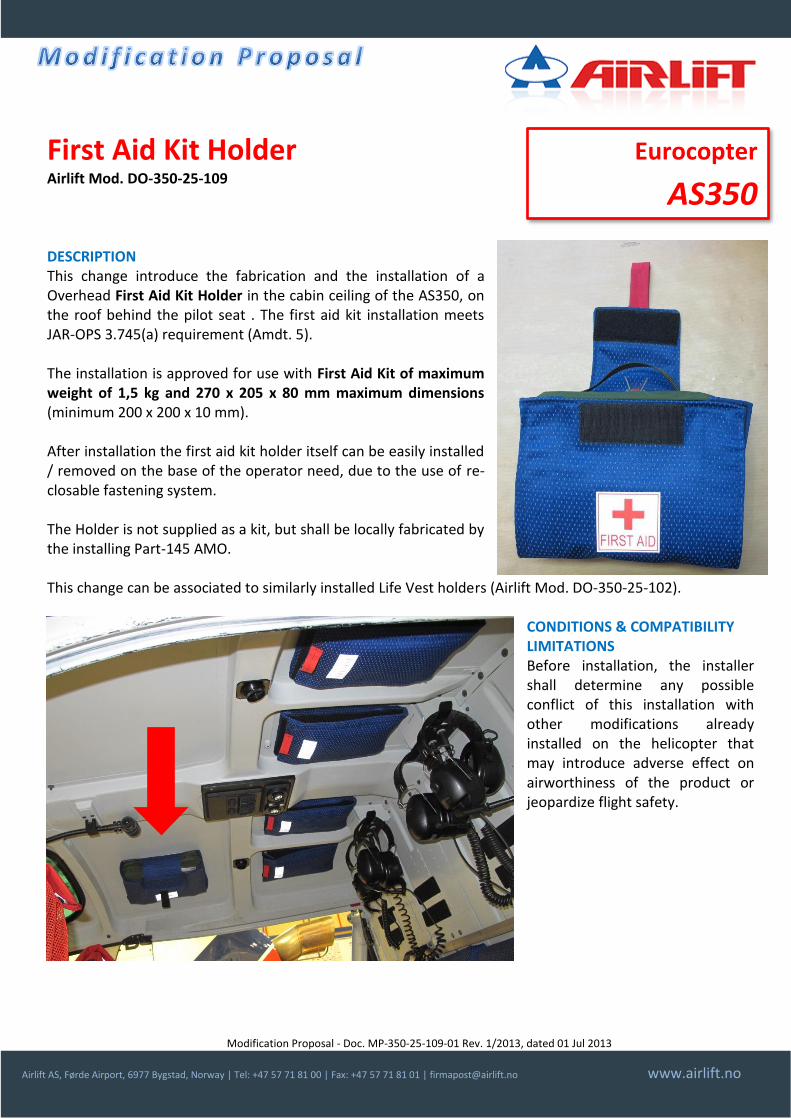
Modification Proposal - Doc. MP-350-25-109-01 Rev. 1/2013, dated 01 Jul 2013
Airlift AS, Førde Airport, 6977 Bygstad, Norway | Tel: +47 57 71 81 00 | Fax: +47 57 71 81 01 | [email protected] www.airlift.no
First Aid Kit Holder Airlift Mod. DO-350-25-109 DESCRIPTION This change introduce the fabrication and the installation of a Overhead First Aid Kit Holder in the cabin ceiling of the AS350, on the roof behind the pilot seat . The first aid kit installation meets JAR-OPS 3.745(a) requirement (Amdt. 5). The installation is approved for use with First Aid Kit of maximum weight of 1,5 kg and 270 x 205 x 80 mm maximum dimensions (minimum 200 x 200 x 10 mm). After installation the first aid kit holder itself can be easily installed / removed on the base of the operator need, due to the use of re-closable fastening system. The Holder is not supplied as a kit, but shall be locally fabricated by the installing Part-145 AMO. This change can be associated to similarly installed Life Vest holders (Airlift Mod. DO-350-25-102).
CONDITIONS & COMPATIBILITY LIMITATIONS Before installation, the installer shall determine any possible conflict of this installation with other modifications already installed on the helicopter that may introduce adverse effect on airworthiness of the product or jeopardize flight safety.
Eurocopter
AS350

Modification Proposal - Doc. MP-350-25-109-01 Rev. 1/2013, dated 01 Jul 2013
Airlift AS, Førde Airport, 6977 Bygstad, Norway | Tel: +47 57 71 81 00 | Fax: +47 57 71 81 01 | [email protected] www.airlift.no
INSTALLATION PLANNING Manpower: Avionic technician: 2 hours. Complexity: Low. DOCUMENTRATION DELIVERED Approval Form, installation instructions, material list, drawings, and instructions for continued airworthiness. KIT No kit is associated to this modification. All parts shall be ordered separately at vendors indicated in the material list. APPROVAL Approval STC Number Type/Model Notes
EASA Minor change AS350 series
Airlift AS is an EASA Part-21 Subp. J Approved Design Organisation (Approval No. EASA.21J.315). PRICE (2013) Description Price range (*)
Installation documentation and Approval Contact us
Delivery time for document package: 2/3 weeks (*) Prices or price ranges indicated is indicative and depends on the actual configuration of the helicopter. Indicated prices are ex works and excludes VAT, packaging and transport. Prices valid at the date of issue of this document. CONTACT INFORMATION For order placement or request of information contact Airlift AS Design Organisation at +47 57 71 81 00 or via email at [email protected] or visit our website www.airlift-doa.com.
For a complete catalogue of our EASA Part-21 Approved Changes visit: www.airlift-doa.com
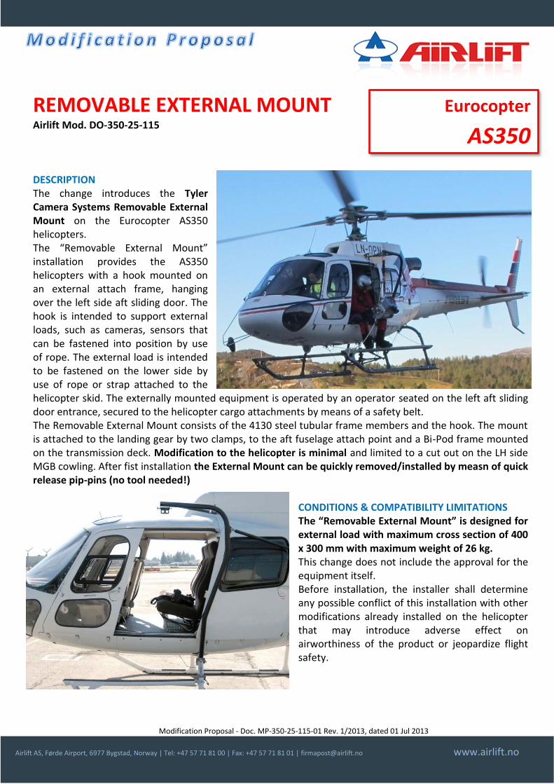
Modification Proposal - Doc. MP-350-25-115-01 Rev. 1/2013, dated 01 Jul 2013
Airlift AS, Førde Airport, 6977 Bygstad, Norway | Tel: +47 57 71 81 00 | Fax: +47 57 71 81 01 | [email protected] www.airlift.no
REMOVABLE EXTERNAL MOUNT Airlift Mod. DO-350-25-115 DESCRIPTION The change introduces the Tyler Camera Systems Removable External Mount on the Eurocopter AS350 helicopters. The “Removable External Mount” installation provides the AS350 helicopters with a hook mounted on an external attach frame, hanging over the left side aft sliding door. The hook is intended to support external loads, such as cameras, sensors that can be fastened into position by use of rope. The external load is intended to be fastened on the lower side by use of rope or strap attached to the helicopter skid. The externally mounted equipment is operated by an operator seated on the left aft sliding door entrance, secured to the helicopter cargo attachments by means of a safety belt. The Removable External Mount consists of the 4130 steel tubular frame members and the hook. The mount is attached to the landing gear by two clamps, to the aft fuselage attach point and a Bi-Pod frame mounted on the transmission deck. Modification to the helicopter is minimal and limited to a cut out on the LH side MGB cowling. After fist installation the External Mount can be quickly removed/installed by measn of quick release pip-pins (no tool needed!)
CONDITIONS & COMPATIBILITY LIMITATIONS The “Removable External Mount” is designed for external load with maximum cross section of 400 x 300 mm with maximum weight of 26 kg. This change does not include the approval for the equipment itself. Before installation, the installer shall determine any possible conflict of this installation with other modifications already installed on the helicopter that may introduce adverse effect on airworthiness of the product or jeopardize flight safety.
Eurocopter
AS350

Modification Proposal - Doc. MP-350-25-115-01 Rev. 1/2013, dated 01 Jul 2013
Airlift AS, Førde Airport, 6977 Bygstad, Norway | Tel: +47 57 71 81 00 | Fax: +47 57 71 81 01 | [email protected] www.airlift.no
INSTALLATION PLANNING Manpower (first installation): Mechanic/sheet metal worker, 6 hours. Subsequent removal/installation takes less that one hour and doesn’t need any tool. DOCUMENTRATION DELIVERED Approval Form, installation instructions, material list, instructions for continued airworthiness, rotorcraft flight manual supplement. KIT Tyler Camera System Removable External Arm. The consumable materials required for the installation are not contained in the material kit and shall be ordered separately at vendors indicated in the material list. APPROVAL Approval STC Number Type/Model Notes
EASA 10043743 AS350 B, BA, B1, B2 and B3
Airlift AS is an EASA Part-21 Subp. J Approved Design Organisation (Approval No. EASA.21J.315). PRICE (2013) Description Price range (*)
Installation documentation and Approval (for use with one kit) Contact us
Kit (one Tyler Camera System Removable External Arm) Contact us
Delivery time for documentation and kit: 5/6 weeks (kit lead time indicated depends upon material availability) (*) Prices or price ranges indicated is indicative and depends on the actual configuration of the helicopter. Indicated prices are ex works and excludes VAT, packaging and transport. Prices valid at the date of issue of this document. CONTACT INFORMATION For order placement or request of information contact Airlift AS Design Organisation at +47 57 71 81 00 or via email at [email protected] or visit our website www.airlift-doa.com.
For a complete catalogue of our EASA Part-21 Approved Changes visit: www.airlift-doa.com

Modification Proposal - Doc. MP-350-25-116-01 Rev. 1/2013, dated 01 Jul 2013
Airlift AS, Førde Airport, 6977 Bygstad, Norway | Tel: +47 57 71 81 00 | Fax: +47 57 71 81 01 | [email protected] www.airlift.no
NOSE EQUIPMENT POD Airlift Mod. DO-350-25-116 DESCRIPTION The Nose Equipment Pod has been developed to introduce on the AS350 helicopter to locate in a single “easy to install” pod different type of survey sensors (such as Cameras, Laser scanners…). The pod is mounted on AirFilm Camera Systems AFSP-1 single pole mount. A variety of different type/models of sensors can be installed inside an aluminum machined pod customized around the customer’s sensors. Internal dampers can be fitted according specific sensor needs. The installation is entirely removable and can be easily fitted without need of special tools. The maximum Pod’s weight, including sensors, is 68 kg (150 lbs) with a maximum frontal area of 2322 cm2 (2,5 sq. ft) and 15 cm (6 in) ground clearance. Computers, data loggers and acquisition units associated to the externally mounted sensors, alongside with a keyboard and a foldable screen can be installed in a dedicated computer rack mounted in the aft cabin.
The computer rack is a standard “19-inch computer rack”, over 80 cm high and 65 cm deep capable of hosting a large quantity of computers for “multiple-sensors” missions. The computer rack can be connected to the radio altimeter and to a dedicated external GPS antenna, mounted over the cabin roof, if such data are needed during data acquisition. The track information are given to the pilot using a 7-inch widescreen LCD display, or alternatively, a lightbar. The rack is powered by a single point “Power Utility Outlet” on the cabin aft wall capable of up to 40A continuous load. The power is controlled via a dedicated on/off push button on the pilot’s console and status shown via a “Utility Power” indicator light on the instrument panel.
CONDITIONS & COMPATIBILITY LIMITATIONS Before installation, the installer shall determine any possible conflict of this installation with other modifications already installed on the helicopter that may introduce adverse effect on airworthiness of the product or jeopardize flight safety.
Eurocopter
AS350
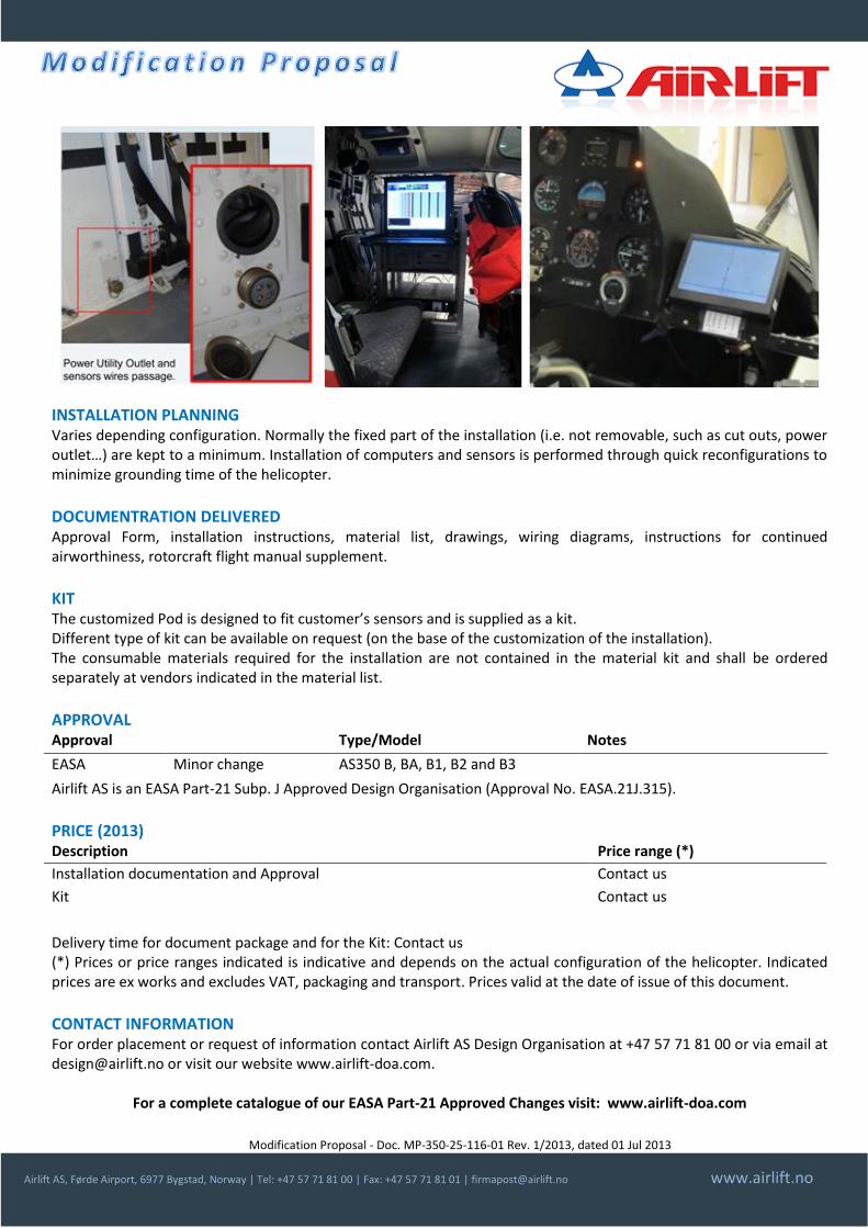
Modification Proposal - Doc. MP-350-25-116-01 Rev. 1/2013, dated 01 Jul 2013
Airlift AS, Førde Airport, 6977 Bygstad, Norway | Tel: +47 57 71 81 00 | Fax: +47 57 71 81 01 | [email protected] www.airlift.no
INSTALLATION PLANNING Varies depending configuration. Normally the fixed part of the installation (i.e. not removable, such as cut outs, power outlet…) are kept to a minimum. Installation of computers and sensors is performed through quick reconfigurations to minimize grounding time of the helicopter.
DOCUMENTRATION DELIVERED Approval Form, installation instructions, material list, drawings, wiring diagrams, instructions for continued airworthiness, rotorcraft flight manual supplement.
KIT The customized Pod is designed to fit customer’s sensors and is supplied as a kit. Different type of kit can be available on request (on the base of the customization of the installation). The consumable materials required for the installation are not contained in the material kit and shall be ordered separately at vendors indicated in the material list.
APPROVAL Approval Type/Model Notes
EASA Minor change AS350 B, BA, B1, B2 and B3
Airlift AS is an EASA Part-21 Subp. J Approved Design Organisation (Approval No. EASA.21J.315).
PRICE (2013) Description Price range (*)
Installation documentation and Approval Contact us
Kit Contact us
Delivery time for document package and for the Kit: Contact us (*) Prices or price ranges indicated is indicative and depends on the actual configuration of the helicopter. Indicated prices are ex works and excludes VAT, packaging and transport. Prices valid at the date of issue of this document.
CONTACT INFORMATION For order placement or request of information contact Airlift AS Design Organisation at +47 57 71 81 00 or via email at [email protected] or visit our website www.airlift-doa.com.
For a complete catalogue of our EASA Part-21 Approved Changes visit: www.airlift-doa.com
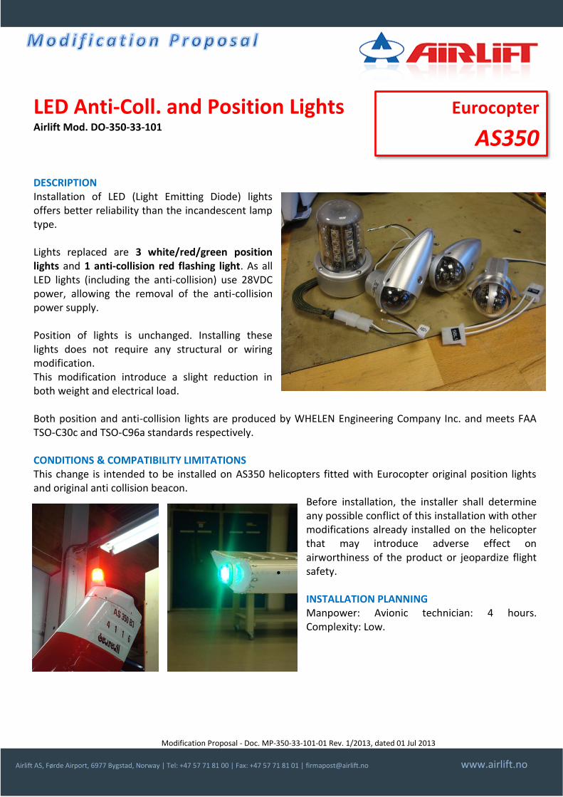
Modification Proposal - Doc. MP-350-33-101-01 Rev. 1/2013, dated 01 Jul 2013
Airlift AS, Førde Airport, 6977 Bygstad, Norway | Tel: +47 57 71 81 00 | Fax: +47 57 71 81 01 | [email protected] www.airlift.no
LED Anti-Coll. and Position Lights Airlift Mod. DO-350-33-101 DESCRIPTION Installation of LED (Light Emitting Diode) lights offers better reliability than the incandescent lamp type. Lights replaced are 3 white/red/green position lights and 1 anti-collision red flashing light. As all LED lights (including the anti-collision) use 28VDC power, allowing the removal of the anti-collision power supply. Position of lights is unchanged. Installing these lights does not require any structural or wiring modification. This modification introduce a slight reduction in both weight and electrical load. Both position and anti-collision lights are produced by WHELEN Engineering Company Inc. and meets FAA TSO-C30c and TSO-C96a standards respectively. CONDITIONS & COMPATIBILITY LIMITATIONS This change is intended to be installed on AS350 helicopters fitted with Eurocopter original position lights and original anti collision beacon.
Before installation, the installer shall determine any possible conflict of this installation with other modifications already installed on the helicopter that may introduce adverse effect on airworthiness of the product or jeopardize flight safety.
INSTALLATION PLANNING Manpower: Avionic technician: 4 hours. Complexity: Low.
Eurocopter
AS350
Modification Proposal - Doc. MP-350-33-101-01 Rev. 1/2013, dated 01 Jul 2013
Airlift AS, Førde Airport, 6977 Bygstad, Norway | Tel: +47 57 71 81 00 | Fax: +47 57 71 81 01 | [email protected] www.airlift.no
DOCUMENTRATION DELIVERED Approval Form, installation instructions, material list, drawings, wiring diagrams and instructions for continued airworthiness. KIT No kit is associated to this modification. All parts shall be ordered separately at vendors indicated in the material list. All light units can be ordered from WHELEN dealers (visit www.whelen.com). APPROVAL Approval STC Number Type/Model Notes
EASA Minor Change AS350 B1, B2 and B3
Airlift AS is an EASA Part-21 Subp. J Approved Design Organisation (Approval No. EASA.21J.315). PRICE (2013) Description Price range (*)
Installation documentation and Approval Contact us
Delivery time for document package: 2/3 weeks (*) Prices or price ranges indicated is indicative and depends on the actual configuration of the helicopter. Indicated prices are ex works and excludes VAT, packaging and transport. Prices valid at the date of issue of this document. CONTACT INFORMATION For order placement or request of information contact Airlift AS Design Organisation at +47 57 71 81 00 or via email at [email protected] or visit our website www.airlift-doa.com.
For a complete catalogue of our EASA Part-21 Approved Changes visit: www.airlift-doa.com
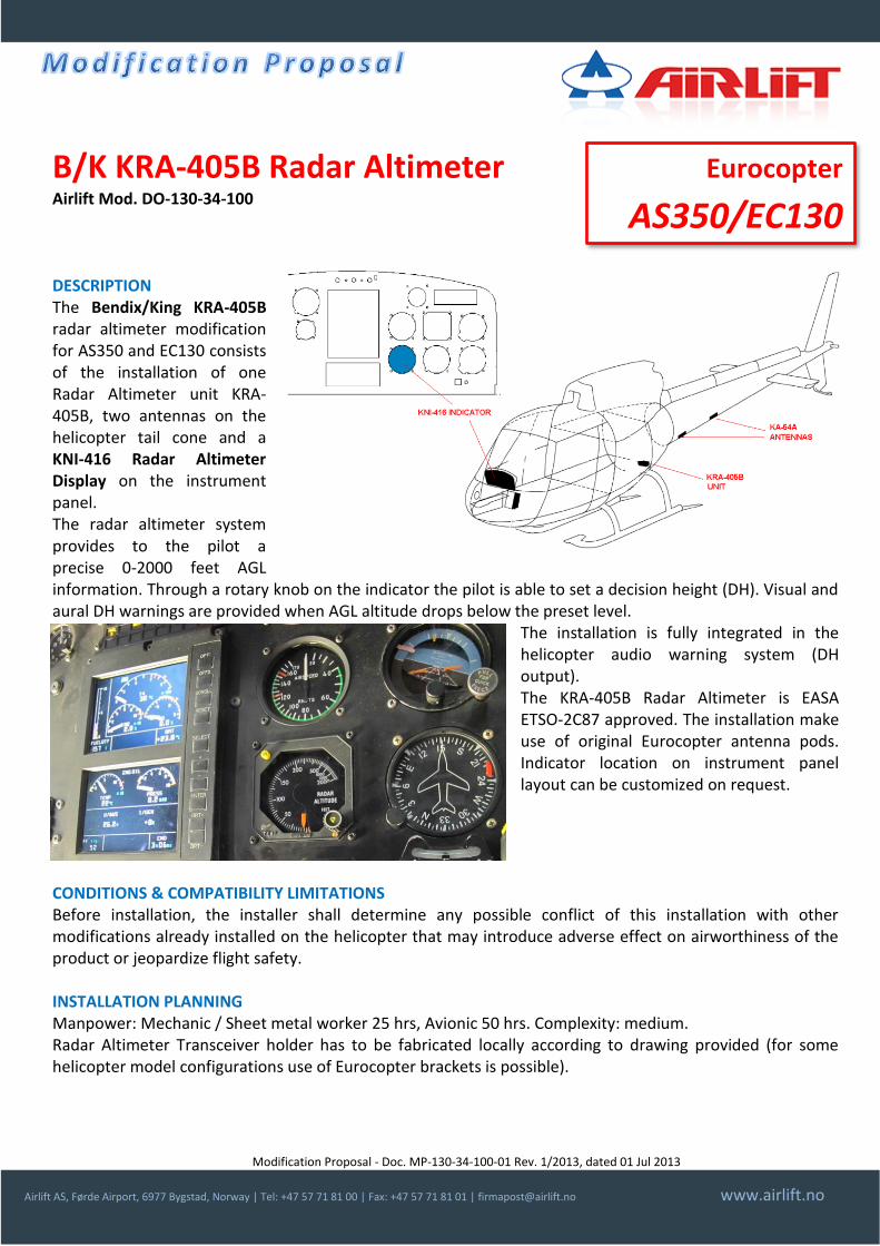
Modification Proposal - Doc. MP-130-34-100-01 Rev. 1/2013, dated 01 Jul 2013
Airlift AS, Førde Airport, 6977 Bygstad, Norway | Tel: +47 57 71 81 00 | Fax: +47 57 71 81 01 | [email protected] www.airlift.no
B/K KRA-405B Radar Altimeter Airlift Mod. DO-130-34-100 DESCRIPTION The Bendix/King KRA-405B radar altimeter modification for AS350 and EC130 consists of the installation of one Radar Altimeter unit KRA-405B, two antennas on the helicopter tail cone and a KNI-416 Radar Altimeter Display on the instrument panel. The radar altimeter system provides to the pilot a precise 0-2000 feet AGL information. Through a rotary knob on the indicator the pilot is able to set a decision height (DH). Visual and aural DH warnings are provided when AGL altitude drops below the preset level.
The installation is fully integrated in the helicopter audio warning system (DH output). The KRA-405B Radar Altimeter is EASA ETSO-2C87 approved. The installation make use of original Eurocopter antenna pods. Indicator location on instrument panel layout can be customized on request.
CONDITIONS & COMPATIBILITY LIMITATIONS Before installation, the installer shall determine any possible conflict of this installation with other modifications already installed on the helicopter that may introduce adverse effect on airworthiness of the product or jeopardize flight safety. INSTALLATION PLANNING Manpower: Mechanic / Sheet metal worker 25 hrs, Avionic 50 hrs. Complexity: medium. Radar Altimeter Transceiver holder has to be fabricated locally according to drawing provided (for some helicopter model configurations use of Eurocopter brackets is possible).
Eurocopter
AS350/EC130

Modification Proposal - Doc. MP-130-34-100-01 Rev. 1/2013, dated 01 Jul 2013
Airlift AS, Førde Airport, 6977 Bygstad, Norway | Tel: +47 57 71 81 00 | Fax: +47 57 71 81 01 | [email protected] www.airlift.no
DOCUMENTRATION DELIVERED Approval Form, installation instructions, material list, drawings, wiring diagrams, instructions for continued airworthiness. KIT No kit is available for this change. Radar altimeter kits comprehensive of KRA-405B transceiver, KNI-416 indicator, KA-54A antennas are available from Bendix King official dealers; antenna brackets, alarm box are available from Eurocopter. The consumable materials required for the installation can be ordered vendors indicated in the material list. APPROVAL Approval STC Number Type/Model Notes
EASA 10036162 AS350 B1, B2 and B3
EASA 10036162 EC130 B4
Airlift AS is an EASA Part-21 Subp. J Approved Design Organisation (Approval No. EASA.21J.315). PRICE (2013) Description Price range (*)
Installation documentation and Approval (one helicopter) 35000-45000 NOK
Delivery time for document package: 2-3 weeks. (*) Prices or price ranges indicated is indicative and depends on the actual configuration of the helicopter. Indicated prices are ex works and excludes VAT, packaging and transport. Prices valid at the date of issue of this document. CONTACT INFORMATION For order placement or request of information contact Airlift AS Design Organisation at +47 57 71 81 00 or via email at [email protected] or visit our website www.airlift-doa.com.
For a complete catalogue of our EASA Part-21 Approved Changes visit: www.airlift-doa.com
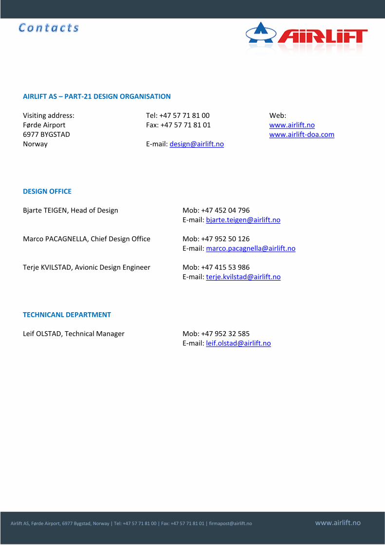
Airlift AS, Førde Airport, 6977 Bygstad, Norway | Tel: +47 57 71 81 00 | Fax: +47 57 71 81 01 | [email protected] www.airlift.no
AIRLIFT AS – PART-21 DESIGN ORGANISATION Visiting address: Førde Airport 6977 BYGSTAD Norway
Tel: +47 57 71 81 00 Fax: +47 57 71 81 01 E-mail: [email protected]
Web: www.airlift.no www.airlift-doa.com
DESIGN OFFICE Bjarte TEIGEN, Head of Design Mob: +47 452 04 796
E-mail: [email protected] Marco PACAGNELLA, Chief Design Office Mob: +47 952 50 126
E-mail: [email protected] Terje KVILSTAD, Avionic Design Engineer Mob: +47 415 53 986
E-mail: [email protected] TECHNICANL DEPARTMENT
Leif OLSTAD, Technical Manager Mob: +47 952 32 585 E-mail: [email protected]