
© Belimo University 2011, All Rights Reserved Enhancing Sustainability Advantages of pressure...
40
© Belimo University 2011, All Rights Reserved Enhancing Sustainability Advantages of pressure independent control valves; basic commissioning of Belimo PI valves.
-
Upload
madeline-williamson -
Category
Documents
-
view
214 -
download
1
Transcript of © Belimo University 2011, All Rights Reserved Enhancing Sustainability Advantages of pressure...
© Belimo University 2011, All Rights Reserved
Enhancing Sustainability Advantages of pressure independent control valves;basic commissioning of Belimo PI valves.

Enhancing Sustainability
First, an analogy between air systems and hydronic systems.
Why are there no more VAV pressure dependent air systems?

Enhancing Sustainability
Air Handling Unit
Return Duct
VVT Boxes
Supply Duct
Bypass Duct
SpaceTemp
Balancing Damper
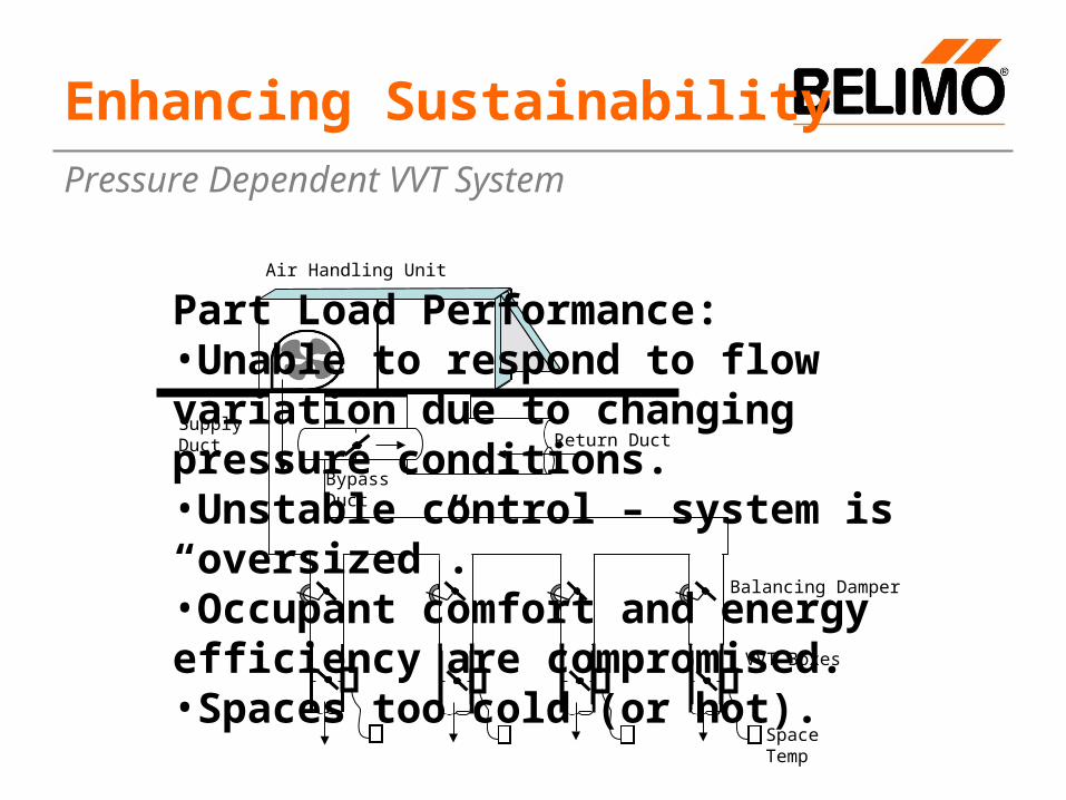
Pressure Dependent VVT System
How many Pressure Dependent VVT systems have you seen lately?
Enhancing Sustainability
Air Handling Unit
Return Duct
VVT Boxes
Supply Duct
Bypass Duct
SpaceTemp
Balancing Damper
Pressure Dependent VVT System
Part Load Performance:•Unable to respond to flow variation due to changing pressure conditions.•Unstable control – system is “oversized”.•Occupant comfort and energy efficiency are compromised.•Spaces too cold (or hot).
Enhancing Sustainability
Temp. Control
Air Flow
ControllerAir Flow
Measurement Device
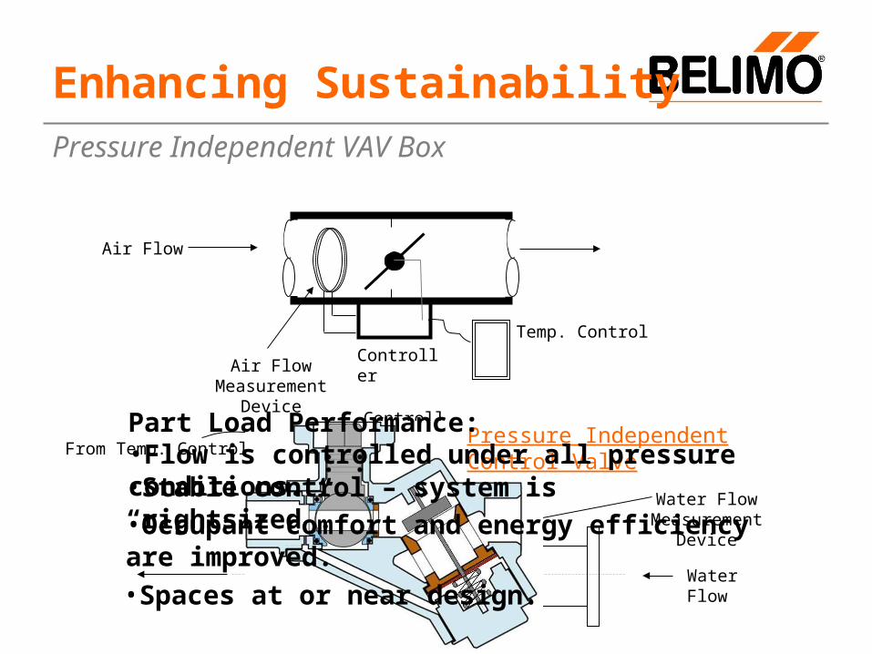
Pressure Independent VAV Box
Water Flow Measurement Device
Water Flow
Controller
From Temp. ControlPressure Independent Control Valve
•Stable control – system is “rightsized”.
Part Load Performance:•Flow is controlled under all pressure conditions.
•Occupant comfort and energy efficiency are improved.•Spaces at or near design.
A PI Control Valve….
Is a 2-way control valve that supplies a precise flow at any given control signal…
Regardless of pressure variations in a system.
It is not just a control valve and flow limiting circuit setter in the same assembly!
Note: Automatic or manual balance valves should NOT be used with PI valves. If they are already installed they should be set WIDE OPEN.
What is a pressure independent control valve?
Pressure Independent Control Valve
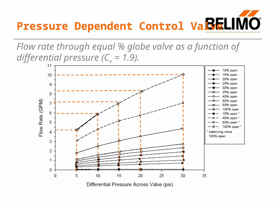
Flow rate through equal % globe valve as a function of differential pressure (Cv = 1.9).
Pressure Dependent Control Valve
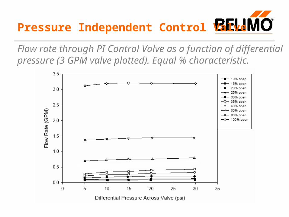
Flow rate through PI Control Valve as a function of differential pressure (3 GPM valve plotted). Equal % characteristic.
Pressure Independent Control Valve
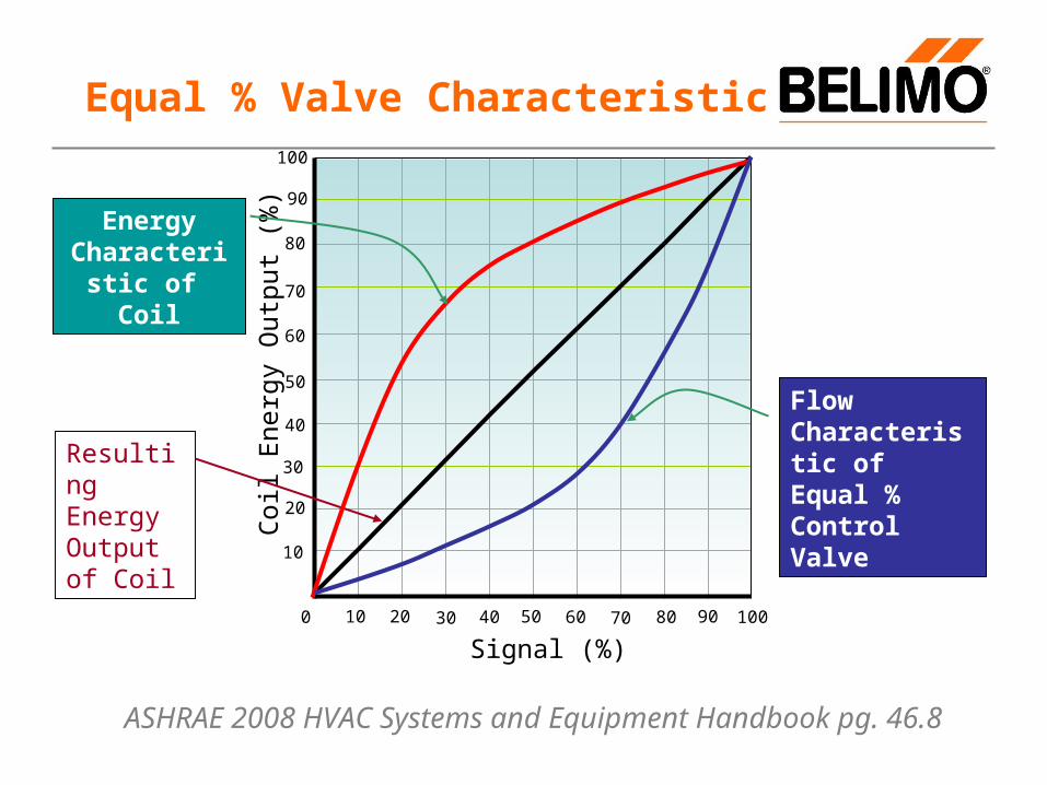
Equal % Valve Characteristic100
0 40 60 80 100
20
40
60
80
10
30
50
70
90
10 20 30 50 70 90
Signal (%)
Coi
l Ene
rgy
Out
put
(%)
Resulting Energy Output of Coil
Energy Characteristic of
Coil
Flow Characteristic of Equal % Control Valve
ASHRAE 2008 HVAC Systems and Equipment Handbook pg. 46.8

Advantages
SAT Setpoint Change Globe Valve Water Flow
The Pressure Dependent Valve loses authorityat part load. In effect, it becomes “Oversized”
•Iowa Energy Center Pressure Independent Valves Study•Chilled Water Closed Loop Test
PICCV Valve Water Flow
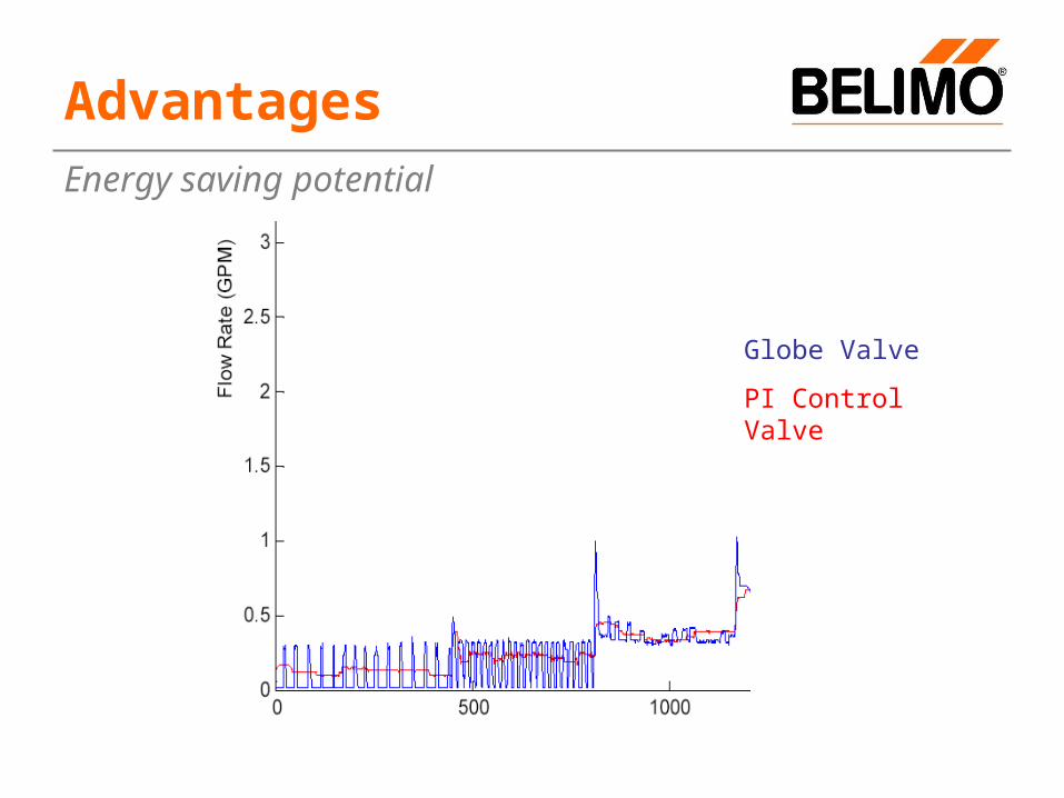
Globe Valve
PI Control Valve
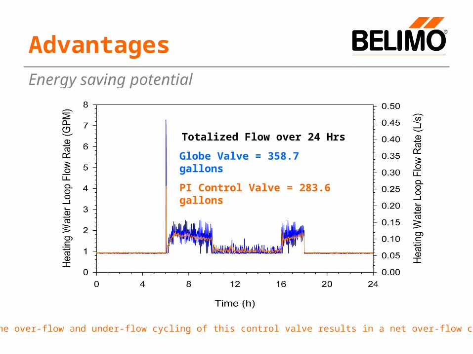
Energy saving potential
Advantages
Energy saving potential
Advantages
Totalized Flow over 24 Hrs
Globe Valve = 358.7 gallons
PI Control Valve = 283.6 gallons
Note: The over-flow and under-flow cycling of this control valve results in a net over-flow condition!
Energy saving potential
Advantages
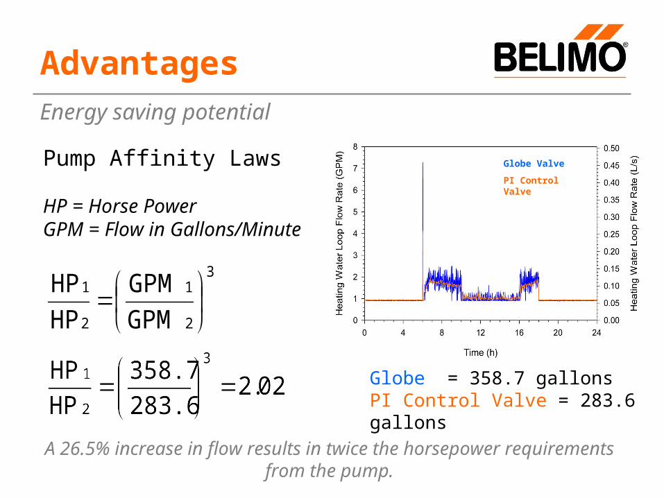
Globe = 358.7 gallonsPI Control Valve = 283.6 gallons
Pump Affinity Laws
HP = Horse PowerGPM = Flow in Gallons/Minute
3
2
1
2
1
GPM
GPM
HP
HP
Globe Valve
PI Control Valve
A 26.5% increase in flow results in twice the horsepower requirements from the pump.
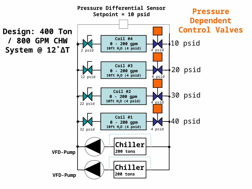
Pressure Differential SensorSetpoint = 10 psid
Chiller200 tonsVFD-Pump
Coil #40 - 200 gpm
10ft H2O (4 psid)
VFD-Pump
Chiller200 tons
Pressure Dependent Control
ValvesDesign: 400 Ton / 800 GPM CHW
System @ 12˚ΔT
40 psid
30 psid
20 psid
10 psid4 psid2 psid
Coil #30 - 200 gpm
10ft H2O (4 psid)
Coil #2 0 - 200 gpm
10ft H2O (4 psid)
Coil #10 - 200 gpm
10ft H2O (4 psid)
4 psid12 psid
4 psid22 psid
4 psid32 psid

T
24TonsGPM
For a given load, flow and ΔT are inversely proportionate. As flow increases, ΔT drops.
Energy saving potential
Advantages
T12
24TonsGPM 800
2TonsGPM 800
Tons2
GPM 800
400Tons
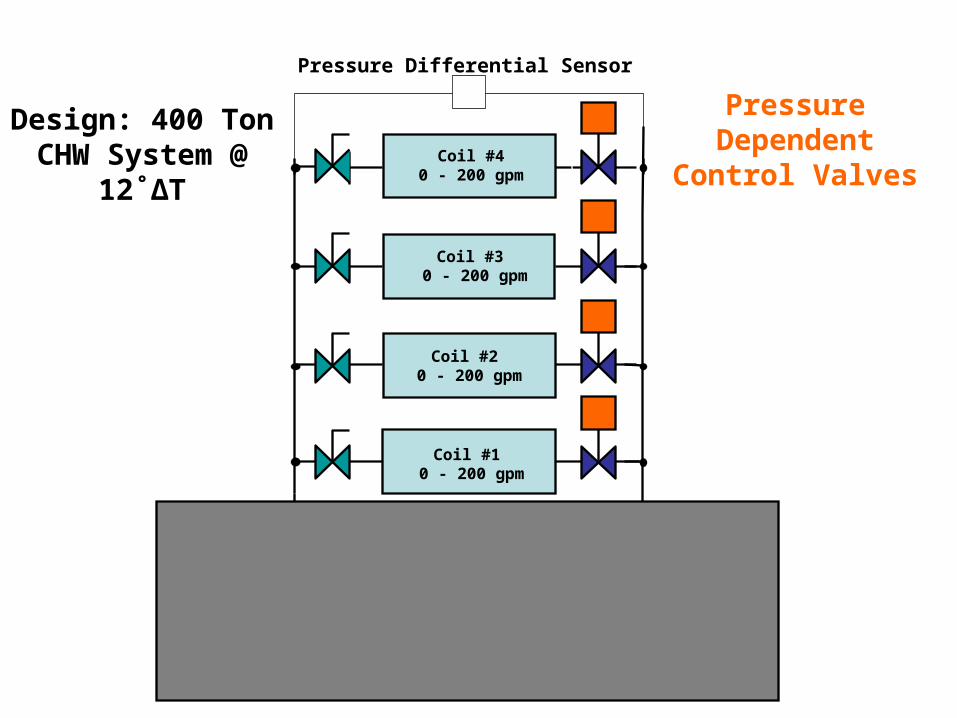
Pressure Differential Sensor
Chiller200 tonsVFD-Pump
Coil #40 - 200 gpm
Coil #3 0 - 200 gpm
Coil #1 0 - 200 gpm
Coil #2 0 - 200 gpm
VFD-Pump
Chiller200 tons
Pressure Dependent Control
Valves
Design: 400 Ton CHW System @
12˚ΔT
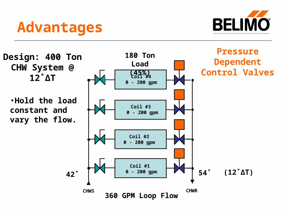
CHWS
Coil #40 - 200 gpm
Coil #3 0 - 200 gpm
Coil #1 0 - 200 gpm
Coil #20 - 200 gpm
CHWR
180 Ton Load(45%)
42˚ (12˚ΔT)
360 GPM Loop Flow
54˚
Advantages
Pressure Dependent Control
Valves
•Hold the load constant and vary the flow.
Design: 400 Ton CHW System @
12˚ΔT

CHWS
Coil #40 - 200 gpm
Coil #3 0 - 200 gpm
Coil #1 0 - 200 gpm
Coil #2 0 - 200 gpm
CHWR
180 Ton Load(45%)
42˚ (10.9˚ΔT)
396 GPM Loop Flow (+10%)
52.9˚
Advantages
Pressure Dependent Control
Valves
Design: 400 Ton CHW System @
12˚ΔT
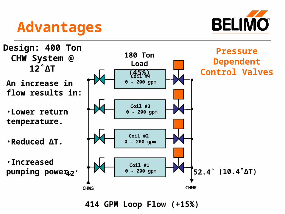
CHWS
Coil #40 - 200 gpm
Coil #3 0 - 200 gpm
Coil #1 0 - 200 gpm
Coil #2 0 - 200 gpm
CHWR
180 Ton Load(45%)
42˚ (10.4˚ΔT)
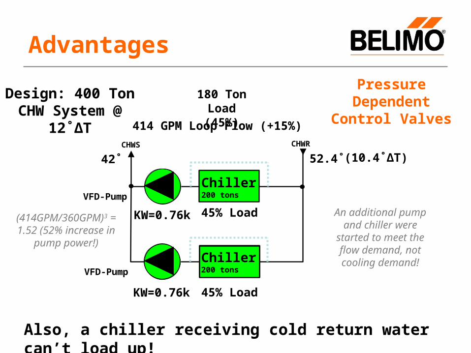
414 GPM Loop Flow (+15%)
52.4˚
Advantages
Pressure Dependent Control
ValvesAn increase in flow results in:
•Lower return temperature.
•Reduced ΔT.
•Increased pumping power.
Design: 400 Ton CHW System @
12˚ΔT
Pressure Differential Sensor
Chiller200 tons
Coil #40 - 200 gpm
Coil #3 0 - 200 gpm
Coil #1 0 - 200 gpm
Coil #2 0 - 200 gpm
Chiller200 tons
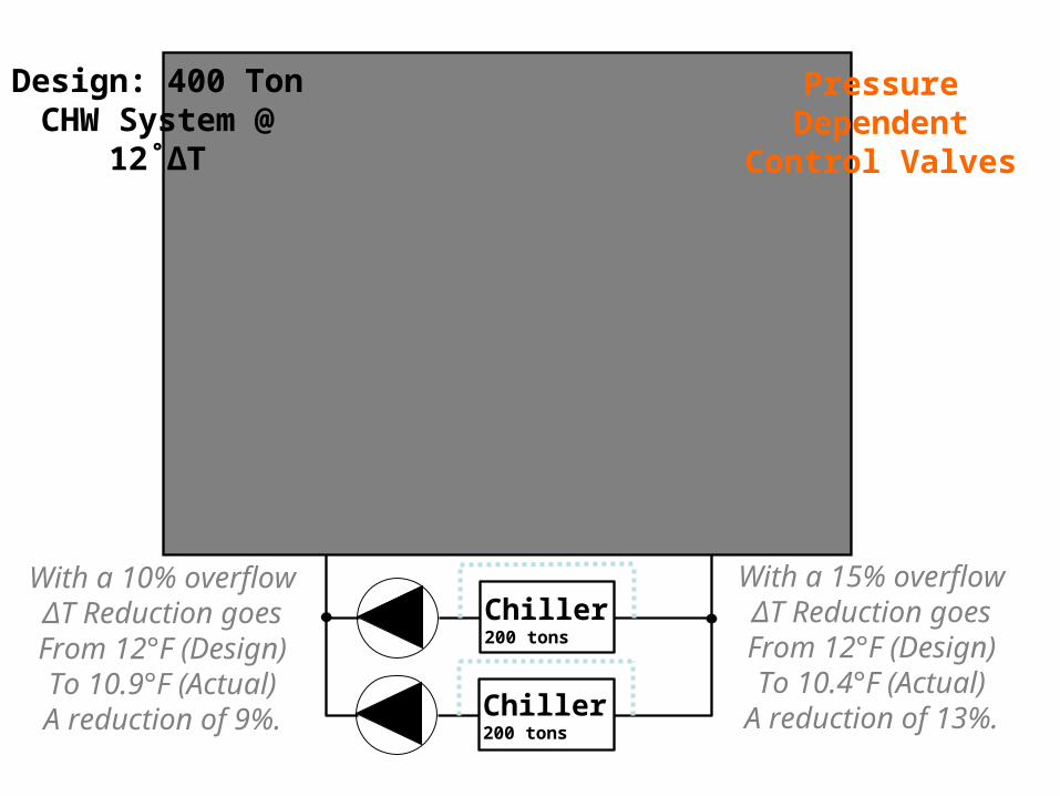
Pressure Dependent Control
Valves
Design: 400 Ton CHW System @
12˚ΔT
With a 15% overflowΔT Reduction goesFrom 12°F (Design)To 10.4°F (Actual)
A reduction of 13%.
With a 10% overflowΔT Reduction goesFrom 12°F (Design)To 10.9°F (Actual)A reduction of 9%.

Chiller200 tonsVFD-Pump
VFD-Pump
Chiller200 tons
180 Ton Load(45%)
42˚ (12˚ΔT)
360 GPM Loop Flow
54˚CHWS CHWR
KW=1.0k 90% Load
Advantages
Pressure Dependent Control
Valves
•Hold the load constant and vary the flow.
Design: 400 Ton CHW System @
12˚ΔT
Arbitrary Value
Chiller200 tonsVFD-Pump
VFD-Pump
Chiller200 tons
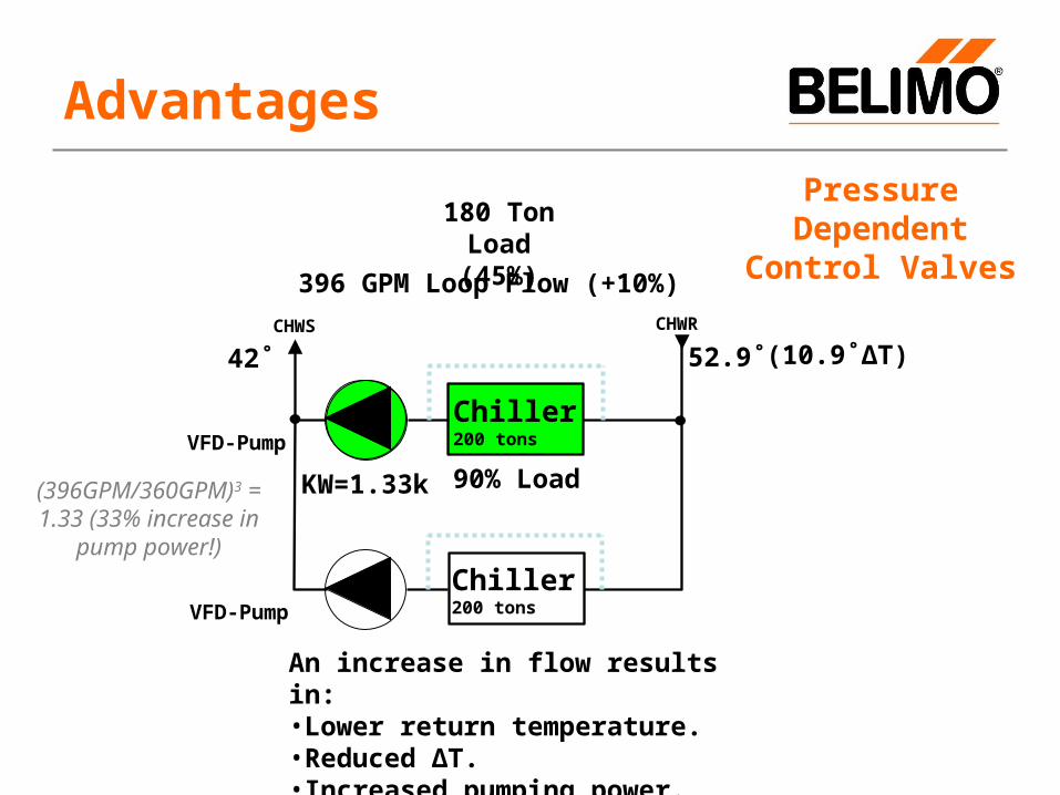
180 Ton Load(45%)
42˚ (10.9˚ΔT)
396 GPM Loop Flow (+10%)
52.9˚CHWS CHWR
KW=1.33k 90% Load
Advantages
Pressure Dependent Control
Valves
An increase in flow results in:•Lower return temperature.•Reduced ΔT.•Increased pumping power.
(396GPM/360GPM)3 = 1.33 (33% increase in
pump power!)
Chiller200 tonsVFD-Pump
VFD-Pump
Chiller200 tons
180 Ton Load(45%)
42˚ (10.4˚ΔT)
414 GPM Loop Flow (+15%)
52.4˚CHWS CHWR
Chiller200 tons
KW=0.76k 45% Load
KW=0.76k
Advantages
45% Load
Pressure Dependent Control
Valves
Also, a chiller receiving cold return water can’t load up!
Design: 400 Ton CHW System @
12˚ΔT
(414GPM/360GPM)3 = 1.52 (52% increase in
pump power!)
An additional pump and chiller were started
to meet the flow demand, not cooling
demand!

Two Solutions for Today’s Hydronic Systems
Belimo PI Valves
PICCV
½” – 2”
0.5 GPM – 100 GPM
ePIV
2 ½” – 6”
105 GPM – 713 GPM
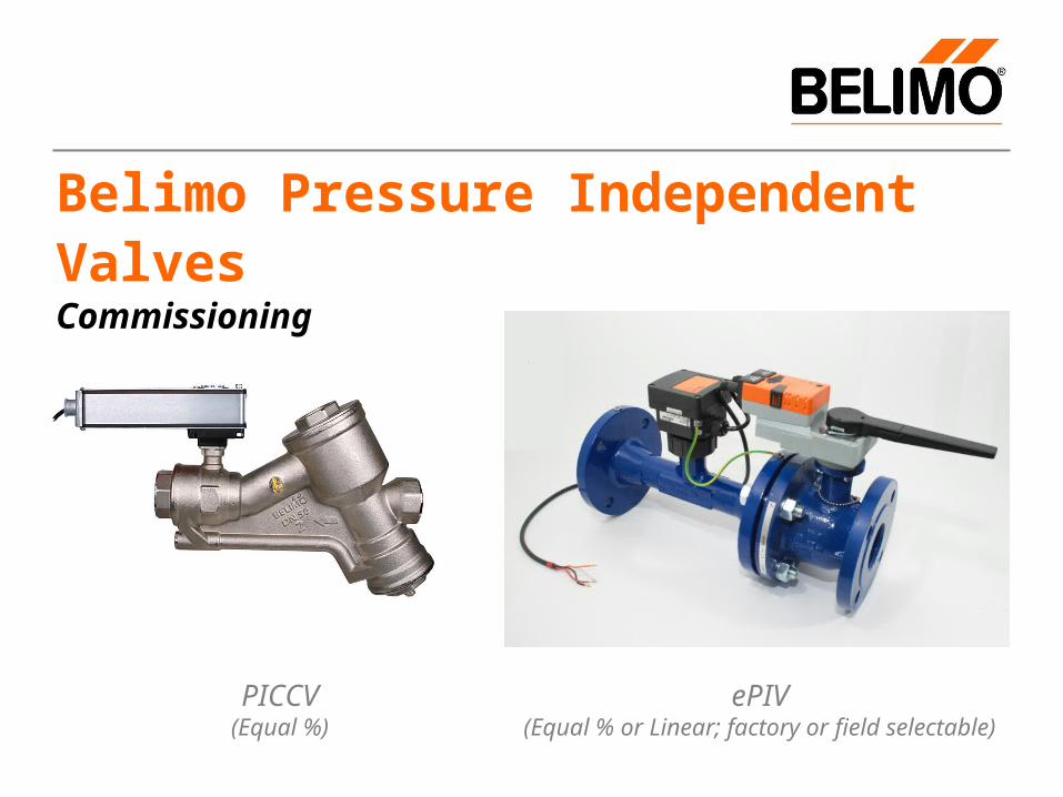
Belimo Pressure Independent Valves Commissioning
PICCV(Equal %)
ePIV(Equal % or Linear; factory or field selectable)
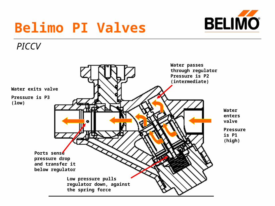
Water exits valve
Pressure is P3 (low)
Water enters valve
Pressure is P1 (high)
Belimo PI Valves
Water passes through regulator Pressure is P2 (intermediate)
Ports sense pressure drop and transfer it below regulator
Low pressure pulls regulator down, against the spring force
PICCV

DDC Controls
AI AO
Process Piping
PICCV Process Flow Diagram
PICCV
Process Piping
AO AI
Control Signal (2-10 vdc (default)/vdc Variable)
Valve Position Feedback (2-10 vdc (default)/vdc
Variable)
Note: Selection is made with PC Tool and ZTH-
GEN/ZTH-PICCV.
Min/Max actuator stroke %
programming per
application design flow.
Internal Mechanical ΔP
Regulator
Equal % Characterized Ball
Valve
Valve Stem and Coupler
Belimo MFT Actuator
P2P3
Note: Shown for functional purposes only. Ancilliary
piping, mechanical regulator and ball valve
are machined into common valve body.
Non-Spring ReturnSpring Return
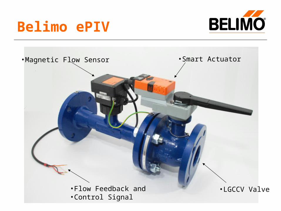
•Magnetic Flow Sensor •Smart Actuator
•LGCCV Valve•Flow Feedback and•Control Signal
Belimo ePIV
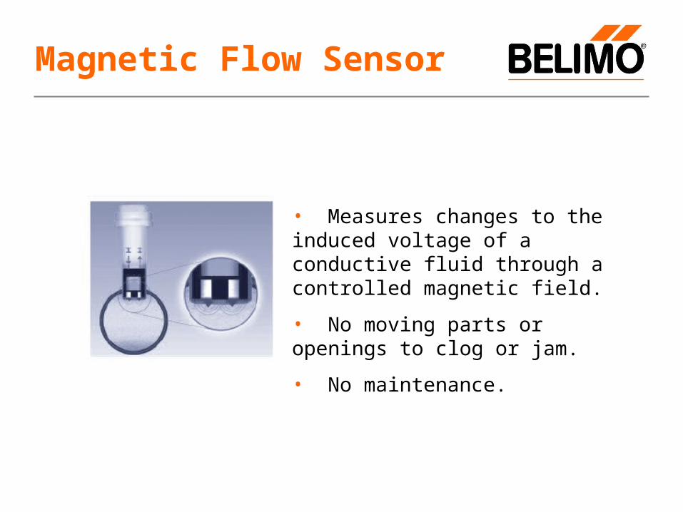
• Measures changes to the induced voltage of a conductive fluid through a controlled magnetic field.
• No moving parts or openings to clog or jam.
• No maintenance.
Magnetic Flow Sensor

Actuator/Flow Tolerances
Controller starts to control if delta "flow actual value" and "flow set value" > 5% (50% of the Flow tolerance)Controller stops to control if delta "flow actual value" and "flow set value" < 1% (10% of the Flow tolerance)
ExampleControl Signal Y = 100GPM (stable no changes)
If the measured Flow is higher then 105GPM Actuator will correct until measured Flow is 101GPM.
If the measured Flow is lower then 95GPM Actuator will correct until measured Flow is 99GPM.
Flow Accuracy +/- 6% of Vnom

Signal Conditioning
(Linear or Equal % Scaling)
Selectable
Internal Control Algorithm
(PV=Input from Flow Sensor)
(SP=Flow Setpoint from DDC)
(CV=Output to Actuator for Valve Positioning)
(FB=Flow Feedback to DDC)
DDC Controls
AI AO
(PV)Velocity to
Flow Conversion
Magnetic Flow Sensor (External
to ePIV Controller)
4-20 milliamp
Actuator (Integral to ePIV Controller)
(CV)
LG-CCV
Process Piping
ePIV Process Flow/Logic Diagram
ePIV
Process Piping
AO AI
Control Signal (2-10 vdc (default)/vdc Variable)
Flow Feedback (2-10 vdc (default)/vdc Variable)
Flow SetpointFlow Feedback
Note: Selection is made with PC Tool v3.5 and higher and ZTH-GEN.
(Release code required)
Closed Loop Control
Valve Stem and Coupler
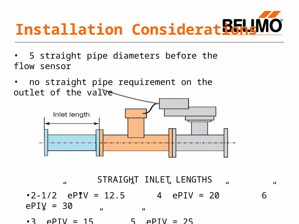
• 5 straight pipe diameters before the flow sensor
• no straight pipe requirement on the outlet of the valve
STRAIGHT INLET LENGTHS
•2-1/2” ePIV = 12.5” 4” ePIV = 20” 6” ePIV = 30”
•3” ePIV = 15” 5” ePIV = 25
Installation Considerations

Actuator must be kept above horizontal!
Installation Considerations

• Cost effective flow sensor technology combined with Belimo’s industry leading intelligent actuators and proven characterized valve technology
• Both non-spring and electronic fail-safe proportional models
• Provides all the benefits of PI valves (accurate flow control, improved efficiency at part load by reduced pumping power, improved waterside ΔT)
• Reduced cost, less weight, less raw materials, more sustainable!
• True flow measurement, available to DDC system through feedback wire
• Glycol concentration up 50% has no effect on flow measurement
• Can be configured for either linear or equal percentage flow characteristic with a simple program change.
Introducing – the ePIVelectronic Pressure Independent Valve

ZTH-GEN
Field adjustable programming tool allows:
•PICCV
•Control/feedback signal
•Custom flows/adjust flows
•Many other parameter adjustments
• ePIV
•Control/feedback signal
•Custom flows/bias adjustment
•Flow coefficient
•Equal % or linear setting
•Many other parameter adjustments
Belimo Field Programming Tool
No external power needed; no battery; powered by actuator 24 vac! Just plug it into actuator.
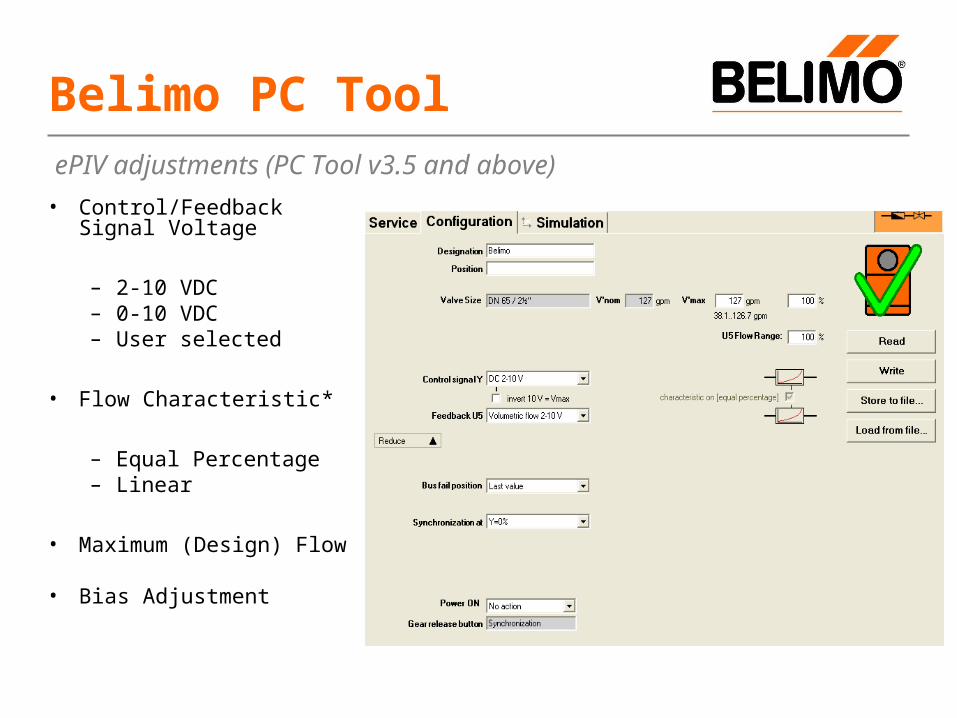
• Control/Feedback Signal Voltage
– 2-10 VDC– 0-10 VDC– User selected
• Flow Characteristic*
– Equal Percentage– Linear
• Maximum (Design) Flow
• Bias Adjustment
Belimo PC Tool ePIV adjustments (PC Tool v3.5 and above)

Additional P/T PORT for verification of 5 psi (11.5 ft H20) minimum differential across the PI Valve.
Commissioning
Minimum ΔP across valve must be verified with PI valve COMMANDED by DDC (or by programming tool) to design
flow, not manually positioned!
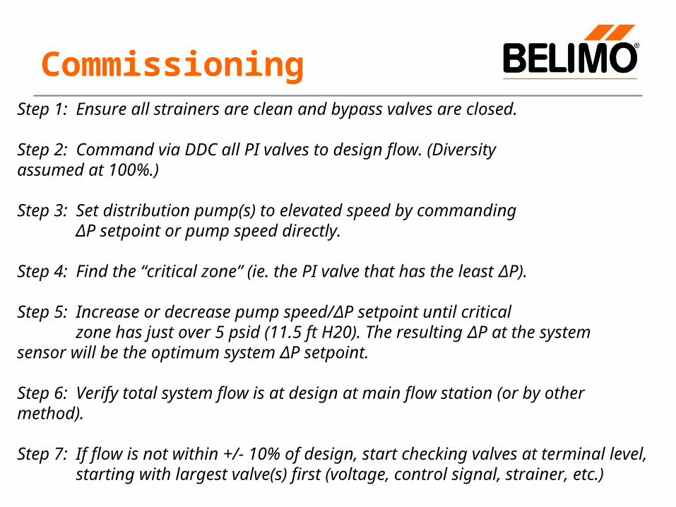
CommissioningStep 1: Ensure all strainers are clean and bypass valves are closed.
Step 2: Command via DDC all PI valves to design flow. (Diversity assumed at 100%.)
Step 3: Set distribution pump(s) to elevated speed by commanding ΔP setpoint or pump speed directly.
Step 4: Find the “critical zone” (ie. the PI valve that has the least ΔP).
Step 5: Increase or decrease pump speed/ΔP setpoint until critical zone has just over 5 psid (11.5 ft H20). The resulting ΔP at the system sensor will be the optimum system ΔP setpoint.
Step 6: Verify total system flow is at design at main flow station (or by other method).
Step 7: If flow is not within +/- 10% of design, start checking valves at terminal level, starting with largest valve(s) first (voltage, control signal, strainer, etc.)
Commissioning
• Belimo PI valves do NOT require that the entire system be placed in full design flow. Each PI valve flow can be verified individually with the rest of the system under normal control.
1) Command valve assembly to design.2) Verify at least 5 psid across PI valve
assembly.3) Verify coil flow as per usual method (coil ΔP
method, etc.)
Link for PI valve commissioning document:
www.piccv.com/pdf/PICCV_Application_Bulletin.pdf

Questions?