DTI · AD-A263 325 Technical Report 1528 November 1992 RUSS Advanced Unmanned Search System (AUSS)...
34
AD-A263 325 Technical Report 1528 November 1992 RUSS Advanced Unmanned Search System (AUSS) Description DTI H. V. Jonesw ~APR2631993 93-08785 Approved for public release; distribution It unlimited. NWq
Transcript of DTI · AD-A263 325 Technical Report 1528 November 1992 RUSS Advanced Unmanned Search System (AUSS)...

AD-A263 325
Technical Report 1528November 1992
RUSS Advanced UnmannedSearch System (AUSS)Description
DTIH. V. Jonesw
~APR2631993
93-08785
Approved for public release; distribution It unlimited.
NWq

Technical Report 1528November 1992
Advanced Unmanned SearchSystem (AUSS) Description
H. V. Jones

NAVAL COMMAND, CONTROL ANDOCEAN SURVEILLANCE CENTER
RDT&E DIVISIONSan Diego, California 92152-5000
J. D. FONTANA, CAPT, USN R.T. SHEARERCommanding Officer Executive Director
ADMINISTRATIVE INFORMATION
This work was performed by members of the Ocean Engineering Division(Code 94), Naval Command, Control and Ocean Surveillance Center, RDT&EDivision, San Diego, CA 92152-5000, under program element 0603713N, projectS0397. The work was performed for the Assistant Secretary of the Navy forResearch and Development, Washington, DC 20350.
Further information on AUSS is available in related reports that represent NRaDefforts through FY 92. A bibliography of these reports may be found at the end ofthis report.
Released-by Under authority ofN. B. Estabrook, Head I. P. Lemaire, HeadOcean Engineering Division Engineering and Computer
Sciences Department
looession For
NTIS GRA&IDTIC TAB 0ljnaanowuned 03
i • Justi..catio
Dintzslbuti on/
AvaJIa-bility Codes
-Avail •ndior•tbat ( special
LH

CONTENTS
INTRODUCTION ....................................................... 1
VEHICLE ... 1... .............. ..... ..... . .......... 1
FORWARD FREE-FLOODING SECTION ............................... 1
CENTER SECTION .................................................. 4
AFT FREE-FLOODING SECTION .................................... 11
ACOUSTIC LINK.................................................. 12
VEHICLE ACOUSTIC LINK ......................................... 12
SURFACE ACOUSTIC LINK ......................................... 13
CONTROL VAN ...................................................... 13
SURFACE COMPUTERS ............................................ 15
VEHICLE CONTROL ............................................... 15
IMAGE PROCESSING............................................ 17NAVIGATION ..................................................... 17
DATA LOGGING ....... ........................................... 17
RECORDING EQUIPMENT .......................................... 17
MAINTENANCE VAN ................................................. 18
U PS .............................................................. 18MAIN BATTERY CHARGER ......................................... 18
TRANSDUCER POLE .................................................. 19
DESCENT STRING .................................................... 19
HANDLING SYSTEMS.............................................. 19
VEHICLE HANDLING SYSTEM ...... ................................ 21
EARS HANDLING SYSTEM ...................................... 23
BIBLIOGRAPHYA ........ ......................................... 25
FIGURES
1. AU SS vehicle ....................................................... 2
2. Vehicle center section (end view) ...................................... 5
3. AUSS vehicle computerc ... ............ ..................... 7
4. Vehicle electronic chassis (side view) ................................... 9
i

CONTENTS (continued)
5. AUSS link operating geometry ....................................... 13
6. Control console .................................................... 14
7. AUSS surface computers ............................................ 16
8. D escent string ..................................................... 20
9. Launch ram p ...................................................... 22
10. EARS launcher ................................................... 24
ii

INTRODUCTION
The Advanced Unmanned Search System (AUSS) was designed to perform broad-area search and contact evaluation to depths of 20,000 feet. The system is based on asingle, untethered, semiautonomous, supervisory controlled vehicle. Without the burdenof a cable, or the need to place a second vehicle in the water for target investigation,this system can reduce present search operation times by an order of magnitude. Thevehicle has a forward speed of 5 knots and a minimum 10-hour search capability.AUSS is self-contained and needs only a suitable support ship to perform searches. 1"Iaddition to the vehicle, the system includes a control van, maintenance van, acousticlink, transducer pole, descent string, and handling systems.
VEHICLE
The AUSS vehicle is an unmanned, untethered, self-propelled submersible designedto withstand the pressures experienced at depths of 20,000 feet. It is 17 feet long, 31inches in diameter, and weighs 2800 pounds. As shown in figure 1, the vehicle ismade up of a free-flooding forward section, a center pressure vessel, and a free-flooding aft section.
FORWARD FREE-FLOODING SECTION
The main components that make up the forward section of the vehicle are the fair-ing, forward vertical thruster, search and recovery (SAR) gear, ascent weights, forward-looking sonar (FLS), obstacle-avoidance sonar (OAS), charge-coupled device (CCD)electronic still camera, and 35-mm camera. Components inside the forward section areconnected electrically to the center section using pressure-compensated, oil-filled wiringharnesses and bulkhead connectors.
All of the components in the forward section are housed in and/or mounted to theforward fairing. The forward fairing is fabricated of Spectra 1000, which is a wovenpolyethylene mat impregnated with resin (similar to fiberglass construction). ThisSpectra-resin composite was chosen because it has a specific gravity very close to thatof water. The forward fairing is attached to the forward titanium endbell, which is partof the center pressure vessel.
The forward vertical thruster is one of two vertical thrusters on the vehicle. It ismounted in a thruster tube integral to the forward fairing. At lower speeds, where theelevators are less effective, the vertical thrusters are used to change and maintain pitchand depth. The forward vertical thruster is a direct drive, pressure-compensated, brush-less, 120-VDC motor with special high-frequency integral motor controller. It is manu-factured for the Naval Command, Control and Ocean Surveillance Center, RDT&EDivision (NRaD), by Industrial Drives and produces .33 hp at 1200 rpm. The motorcontroller operates at approximately 40 kHz so it will not interfere with the acousticlink.
1

0. zp. 00
0 #
(#2 Z. C) c
0 z
E W E-
x rn W
F-.cCo
0) E
0UU
L) 0

The vehicle's SAR gear includes a recovery float with release, a strobe light, andan RF beacon. Upon surfacing, the recovery float is released, and the strobe light andRF beacon are erected. The recovery float is made of syntactic foam that has beencovered with a Spectra-resin skin. The float is secured to one end of a 80-foot-longpolypropylene line that is also secured to the vehicle. This line is grappled and usedfor vehicle recovery. The strobe light is a Novatech Designs Ltd., model ST 400ARxenon flasher. The strobe has an adjustable range of 2 to 4 nautical miles. The RFbeacon, also from Novatech, is a model RF 700AR. This RF beacon has a range of 4to 6 miles to a vessel and up to 22 miles to an aircraft.
The vehicle's two ascent weights are made of 36-pound lead forms attached to cor-rosive link assemblies. These weights are held into pockets in the forward fairing bysolenoid-operated, weight release mechanisms. When the ascent weights are dropped,the vehicle becomes positively buoyant and returns to the surface for recovery. In anemergency, the ascent weights are dropped automatically to bring the vehicle to thesurface. The conditions that may cause this are as follows: (1) The vehicle has notreceived an acoustic link communication for a specific period of time (usually 45minutes). (2) The main silver-zinc battery voltage has dropped below allowable limits.(3) An individual cell voltage in the main battery has dropped below allowable limits.(4) The emergency backup battery voltage has dropped below allowable limits. (5) Thevoltage across any of the ascent or descent weight release solenoid activation capaci-tors has dropped below allowable limits. (6) Water is detected by leak detect circuitsplaced throughout the interior of the pressure hull.
If for some reason the vehicle cannot drop the ascent weights, the corrosive linkswill dissolve sufficiently to drop the weights in approximately 30 hours (from launch).
The FLS consists of an EDO Corporation model 764, mechanically scanned headassembly and custom AUSS interface and processing electronics. The transducer oper-ates at 100 kHz and has a horizontal beam of 1.80 and a vertical beam of 60*. TheFLS can be mechanically scanned from 90* port to 90* starboard in 1.80 increments.The positioning of the sonar head is directly under computer control so that partialscans from and to any head position can be directed by the operator.
The OAS is used to detect obstructions that the vehicle may encounter. It consistsof an 1TC model 3355 transducer and custom AUSS interface and processing electron-ics. The transducer operates at 267 kHz, has a narrow vertical beam of 5* and a widehorizontal beam of 60*. This beam pattern will make it possible for the vehicle to dis-criminate between bottom returns and reflections of sonar energy from an object in thewater column that is in the path of the vehicle. At this time, the OAS consists of hard-ware only and is not operational.
The CCD camera hardware consists of a Marine Imaging Systems MKII cooledCCD camera head, lens, and control electronics mated to custom AUSS computerhardware. The camera head and lens are mounted in a custom AUSS titanium pres-sure housing secured to the forward fairing. The CCD camera is cooled to minimizethermal noise and thus increase sensitivity. All images are provided as 14-bit digitized
3

information at spatial resolutions up to 576 by 384. The cait -a has a horizontal fieldof view of 45* and a vertical field of view of 31 .
The 35-mm camera is a modified Photosea model 1000. It is powered directly fromthe vehicle and has a 50" ..jrizontal and 35* vertical field nf view. The camera has abulk film magazine that can handle up to 250 exposures per load, and a data chamberprovides a time stamp option on each frame as it is exposed. The triggering of the 35-mm camera is directly under computer control by direction of the operator. The 35-mm camera is generally used only for documentation purposes, while the CCD camerais used for search and evaluation.
CENTER SECTIONThe center section is a pressure vessel housing most of the vehicle's electronics,
along with the vehicle's computers, batteries, and trim system (figure 2). In addition toproviding a dry environment, the pressure vessel also provides buoyancy due to aweight-to-displacement ratio of 0.58. Mounted to the outside of the pressure vessel areport and starboard side-looking sonar (SLS) transducers along with the vehicle acousticlink transducer.
The pressure vessel is made up of a cylindrical pressure hull and two hemispheres(endbells). The pressure hull is a graphite-fiber-reinforced plastic (GFRP) compositewith a wall thickness of 2.5 inches. The composite structure is filament wound using aprocess in which bundles of epoxy-wetted graphite filaments are wrapped around amandrel with alternating hoop and axial winds. Hoop filaments are normal to the cylin-der axis (90*) and axial filaments are parallel to the cylinder axis (0°). The hoop-to-axial filament ratio from the cylinder inside diameter through the first 1.0 inch of wallthickness is 2.5 to 1. A 2-to-1 ratio is used for the remainder of the wall thickness,except for the final layer, which is a hoop layer. These filament ratios are usedbecause hoop stress is twice the axial stress in a cylindrical pressure vessel. A titaniumcoupling ring is bonded to each end of the GFRP cylinder using epoxy resin. Thesetwo coupling rings each have a single o-ring groove for face sealing to the endbells.Each endbell is a one-piece titanium machining. Vacuum along with the external waterpressure is the primary mechanism for holding the endbells to the pressure hull.Clamp bands act as fairings and also hold the vehicle together if vacuum is lost. Inorder to electrically connect the vehicle's center section to the forward and aft sections,each endbell is equipped with eight bulkhead connectors. These connectors are 14-pinD.G. O'Brien number 1380018-101 with titanium housings. The pressure vessel hasbeen subjected to hydrostatic pressure testing to 10,000 psi.
The vehicle's main power comes from a 20-kWh silver-zinc battery. The silver-zincbattery is rechargeable and uses potassium hydroxide liquid electrolyte. The battery ismade up of four packs with 20 cells each. The battery cells are manufactured forNRaD by Whittaker-Yardney Power Systems and are model NRI40DC-1. AU cells arewired together in series to provide 120 VDC to the vehicle. Each battery pack ishoused in a custom Spectra 1000 and resin composite battery box. Also located withinthe battery box are cell monitor boards. These custom monitors sequentially step
4

LjLiJ L I *jtJ
u -,-IL) <I
0 PQ m
_j 0 0
4a
C.
LjU
Rro 3
u
C4 z<L u LC
WW >-<
5
through each cell of the foue bL.ttery packs and provide cell voltages. The monitors areused to prevent the cell voltages from dropping below an allowable limit when dis-charging or rising above an allowable limit when charging. The four battery boxes arehoused inside the pressure hull, two to the port and two to the starboard of the elec-tronics chassis, as shown in figure 2.
If the vehicle's main power supply should fail for any reason, an emergency batteryassembly provides approximately 1 hour of emergency processor operation (the errver-gency computer function is resident in the center bit bus). The emergency battery ismade up of 19 nickel cadmium battery cells. Each cell is a Sanyo Energy (USA) Cor-poration model KR-2800D with a nominal capacity of 2.8 amp-hours at a nominal volt-age of 1.2 volts. These battery cells are connected in series and mounted in a customsheet metal box.
Figure 3 is a block diagram of the vehicle computers. The system divides into twomajor sections: the main vehicle computer (MV) section (which includes the bit-buscontrollers) and the search sensor and communications computers. Th'e search sensorand communications computers consist of the vehicle sensor (VS), image manipulationprocessor (IMP), digital signal processor (DSP), vehicle acoustic link (VA), and vehiclesensor logger (VSL). Except for the VSL, all vehicle computers use Intel 80386 centralprocessors and are mounted in Multibus HI card racks in the electrical chassis. TheVSL is a PC-compatible, 80286 Little Board Computer with a 200-MB removable harddrive and is mourned on top of the electrical chassis. The VSL computer uses a DOSoperating system and software written in C. All other vehicle software is written inPLJM and is run under the RMK realtime operating system.
The MV computer controls the motion and activities of the vehicle. The MV soft-ware includes heading, depth, altitude, pitch, and speed control algorithms for bothhover (vertical thruster control of depth/altitude for low forward speeds) and transit(elevator control of depth/altitude for higher speeds) modes. The MV is responsible forobtaining and handling navigation and control sensor information directly and throughthe main computer bus from the bit-bus controllers. MV software is also responsiblefor the higher level control of the vehicle through maneuvers such as SLS search pat-terns, hovering over a target, and photomosaic search patterns. The MV also monitorsseveral critical vehicle functions and takes emergency actions based upon the status ofthese functions. Most emergency conditions result in the two ascent weights beingdropped and the vehicle coming to the surface for recovery. If the MV fails, the emer-gency computer, resident in the center bit bus, will take over the emergency functions.
The VS computer serves as the master controller for the search sensor and commu-nication computers. It also controls all data communication over the acoustic link.
The IMP computer serves as the interface and first-level processing node for allvehicle search sensors, and passes and retrieves data from the VSL.
The DSP computer serves as a slave to the IMP, performing secondary dataprocessing functions for sensor data, including data compression.
6

0. VLiCL i
W -mC4Z i4
0 L M C
Li u> L z
(4J U, Z)
z z
CL U
0 0pC.)
co o
L,~LJ LJ
m ca.
o (Z C.)
0 C3" L u
z V
(U
7C

The VSL was designed to provide onboard disk storage and retrieval forunprocessed sensor image data under control of the IMP. It is presently being used tostore flight recorder data for post-dive analysis.
The VA controls the vehicle acoustic link electronics. It passes all data downlink tothe vehicle and uplink from vehicle to surface. The VA function is similar to the sur-face acoustic link, which is located in the control van, but has additional acoustic navi-gation capabilities.
The AUSS vehicle was designed with an electronic chassis that can easily be slidinto and out of the center of the pressure hull (figure 4). In addition to the vehiclecomputers, this electronics chassis contains the gyrocompass, angle and angular ratesensors, weight release circuits, power amps, computer power converters, and powerdistribution panel. Extra space has been designed into the electronics chassis to allowfor future expansion.
The gyrocompass (gyro) system is a Robertson-Shipmate Incorporated "Subsea"model. The gyro was repackaged for AUSS and is used to determine the heading ofthe vehicle within +/-0.5". This information is sent to the MV computer and used withDoppler sonar information to determine vehicle velocity vectors. The gyro is also usedwith yaw rate feedback in the heading control loop.
AUSS is equipped with sensors to measure the roll angle, pitch angle, pitch rate,and yaw rate. Both of the angle sensors are manufactured by Humphrey Incorporatedand have a +/I90" range. The roll angle sensor is model CP17-0661-1 and the pitchangle sensor is model CP49-0131-1. The pitch and yaw rate sensors are both WatsonIndustries Incorporated model ARS-C121-1A with a range of +/-30*/second. The rollangle and pitch angle sensors provide feedback for both operator information andDoppler compensation (velocity correction). The pitch angle, pitch rate, and yaw ratesensors along with the gyro, provide feedback used to stabilize the vehicle flight con-trol loops.
The AUSS vehicle has three weight release circuits, one for the descent string andone each for the ascent weights. Each of these custom electrical circuits includes acapacitor, a charge circuit, and a relay to connect the charged capacitor to the weightrelease solenoid. These circuits can be activated by either the MV computer, emer-gency computer, or emergency transponder.
Amplifiers are used to power the acoustic link transducer, navigation transponder,FLS transducer, OAS transducer, and two SLS transducers. These custom-built poweramps vary primarily in power output from application to application. The acoustic linkamp has a 100-watt output; the navigation amp, 100 watts; FLS amp, 500 watts; OASamp, 50 watts; and the two SLS amps, 1000 watts.
The electrical chassis contains 15 DC-to-DC power converters. Six of theseconverters are for the MV computer, eight for the sensor computers, and one for thecenter bit bus. All of these power converters are Vicor VI-200 Series convertersmodified for each application with custom AUSS electronics.
8

'4-
L)J
LO(6
M
LLJ-Eu
(6 0
LCLC
aaz"
<.
Is) Co
1 0~
V'4
-m.-
LLJ
9c

Located at the aft end of the electrical chassis is a power distribution panel. Thiscustom AUSS panel fuses and distributes power from the main batteries to the power-consuming hardware throughout the vehicle. Also included on this panel is a currentsensor to measure the battery power used so estimates of power remaining can bemade.
Additional electronics are located in the titanium endbells of the pressure section.The forward endbell houses the 35-mm camera power converter, FLS power converter,CCD electronics, and forward vertical thruster power filter circuit. The aft endbellhouses the aft power supply assembly, Doppler sonar electronics, aft endbell powerrack, three thruster power filter circuits, and the vehicle computers' aft bit-bus control-ler. This is the only part of the vehicle computers located outside of the electronicschassis. The aft power supply assembly contains eight DC-to-DC power converters.Four of these converters are for the Doppler sonar, two for the strobe lights, one forthe elevator stepping motors, and one for the navigation transponder. All of the powerconverters in the endbells are Vicor VI-200 Series converters modified for each specificapplication with custom AUSS electronics. The CCD electronics are used to control theCCD camera, which is located in the forward section of the vehicle. The CCD elec-tronics are part of the Marine Imaging Systems MKII CCD system and are used aspurchased. The four power filter circuits for the forward vertical, aft vertical, portmain, and starboard main thrusters are all identical and custom to AUSS. They areused to reduce the impact of conducted and radiated electromagnetic interference(EM) on the vehicle's sensors. The Doppler sonar electronics are part of thepurchased EDO model 4235 Doppler sonar system. The Doppler sonar head is locatedin the aft section of the vehicle and is included in that description.
Leak detector circuits are strategically placed within the pressure hull and endbells.The placement of the leak detector circuits allows at least one of them to functionwhether the vehicle is descending, ascending, or operating horizontally. These detectorsuse custom AUSS hardware and are electrically connected to both the main vehiclecomputer and the emergency computer resident in the center bit bus. If seawater con-tacts one of these leak detectors, both the main vehicle computer and the emergencycomputer would automatically activate the ascent and descent weight releases,terminating the dive.
The SLS consists of two side-mounted EDO model 6645 transducers and customAUSS interface and processing electronics. The transducers have fixed horizontal andvertical beams of 3/4° and 600, respectively. The port SLS operates at 100 kHz andthe starboard SLS operates at 105 kHz. The port and starboard transducers aremounted to the outside of the pressure hull in protective pods bolted to the hull'stitanium end rings.
The weight shifter assembly, located under the starboard battery cells, is controlledby the MV computer and is used to statically trim the vehicle in the fore and aftdirection (pitch). This assembly includes a custom 10-pound lead weight that is movedin the fore and aft direction by a motorized power screw. The motor used is a
10

Superior Electric Company SLO-SYN model M063-LS06 DC stepping motor. The
power screw is a modified Nook Industries Incorporated #12032.
AFT FREE-FLOODING SECTION
The main components that make up the aft section of the vehicle are the fairing,main thrusters, aft vertical thruster, elevator assembly, Doppler sonar, navigationtransponder, emergency transponder, and strobe lights. Components inside the aft sec-tion are connected electrically to the center section using pressure-compensated, oil-filled wiring harnesses, and bulkhead connectors.
All components in the aft section are housed in and/or mounted to the aft fairing.Like the forward fairing, the aft fairing is a Spectra 1000 and resin composite. The aftfairing is attached to the aft endbell, which is part of the center pressure vessel.
The AUSS vehicle has two main thrusters that are used to propel and steer thevehicle. As shown in figure 1, these thrusters are angled slightly to provide a largerturning moment about the center of the vehicle. Like the forward vertical thruster, themain thrusters are direct drive, pressure-compensated, brushless DC motors with spe-cial high-frequency integral motor controllers. The main thrusters operate at 120 voltsand produce .75 hp at 1000 rpm. They are manufactured for NRaD by IndustrialDrives.
The aft vertical thruster is mounted in a thruster tube integral to the aft fairing. Itis identical to the forward vertical thruster described earlier in this report.
At speeds above approximately 1.5 knots, elevators are used to change and main-tain the pitch and depth of the vehicle. The elevators are fiberglass and are positionedusing a custom worm gear speed reducer and stepping motor. The gear box is actuallya modified version of the boxes used in the M~k 46 torpedoes. The motor is a SuperiorElectric Company (SLO-SYN) model M063-LS06 DC stepping motor with a modifiedshaft.
The Doppler sonar system is an EDO Corporation model 4235. The transducerarray consists of four acoustic sonar element assemblies aligned at 900 incrementsaround a high-pressure housing. The elements are 60° relative to the horizontal andhave a conical beamwidth of 5. This unit has a range of 4 to 300 feet above the bot-tom. It is used in conjunction with the gyrocompass (located in the vehicle center sec-tion) to determine the velocity vector of the vehicle relative to the ocean bottom and toself-navigate the vehicle during autonomously run search tracks. The Doppler sonar isalso used to determine the altitude of the vehicle above the bottom and the water tem-perature.
The navigation transponder is made up of a ITC 3166 transducer and custom elec-tronics located in the acoustic link processor. The transducer is used to transmit only.Interrogation of the navigation transponder is done through the acoustic link. The navi-gation transponder is used as a beacon during mission tracking and to interrogate net-works of deep-ocean transponders (if used) for long baseline tracking of the vehicle.
11

The emergency transponder is used for both vehicle tracking and as an emergencybackup. This transponder is a SonaTech Incorporated model NT-029. It is equippedwith an optional 12-month battery pack and commandable dual-relay output for operat-ing external devices. The emergency transponder responds to interrogations from theship-mounted transducer pole for short baseline tracking of the vehicle. Since thetransponder has its own battery pack, an otherwise dead vehicle can be tracked for anextended period of time. One of the transponder's commandable relays is used as abackup method of releasing the vehicle ascent weights. The second relay will reset thesensor computer if vehicle power is available. If vehicle power is off, a command tothis second relay will turn it on.
Two Photosea model 1500SX strobe lights are mounted in custom titanium hous-ings. These strobes are 150 Joule each and obtain power from the main vehiclebatteries through a Vicor model VI-253-CU, 120-VDC to 24-VDC converter located inthe pressure vessel. The strobes are located in the aft section to provide maximumseparation from the cameras. This provides the best source/receiver separation andtherefore minimizes backscatter. The strobes are fired by the computers and synchro-nized with the CCD and 35-mm cameras.
ACOUSTIC LINK
What makes an unmanned, untethered, supervisory controlled system like AUSSpossible is a high-data-rate digital acoustic telemetry system. The AUSS acoustic linksystem is used to send supervisory commands to the vehicle and provide the operatorswith sensor data and status information. The vehicle sensor data transmitted are theFLS, SLS, and CCD camera images. The status information includes the vehicle depth,altitude, forward velocity, heading, Doppler position, and emergency information.
The acoustic link uses directional transducers operating from 8 to 14 KHz drivenwith up to 100 watts (for 20,000-foot vehicle depth) to achieve 1200, 2400, or 4800bps half-duplex communications between the surface and the vehicle. Reliable low-error-rate communications up to 10 km are possible in water depths exceeding 610meters provided the horizontal distance between the ship and vehicle does not exceedthe depth of the vehicle (90° cone). See figure 5.
VEHICLE ACOUSTIC LINK
The vehicle acoustic link transducer is an International Transducer Corporationmodel 1TC-3166, which has approximately a 90° conical beam pattern. This transduceris mounted to the top of the vehicle with the beam pattern directed upward from thevehicle to the surface. The acoustic link transducer was placed on the pressure hull asa result of beam pattern experiments. These experiments showed that mounting thetransducer on a pressure hull can increase the front-to-back ratio (the ratio between thegain in the region of a 900 cone above the vehicle and the gain below the vehicle).The pressure hull helps prevent reflections from the sea bottom during transmit andreject reflections from the sea bottom during receive.
12

OCEAN SURFACE
SURFACE TRANSDUCER
< 90degree <10km
>610 m
OCEAN BOTTOM
Figure 5. AUSS link operating geometry.
SURFACE ACOUSTIC LINK
The External Acoustic Relay System (EARS) is the surface portion of the acousticlink. EARS is a shallow-towed submersible (towfish) containing a transducer and theacoustic link preamp. The EARS towfish is a 4-foot Endico V-fin attached to 500 feetof cable. During operations, the EARS towfish is towed behind the surface ship atdepths between 50 and 300 feet. By doing this, the surface communication link func-tion is decoupled from the noise and motion of the ship. The transducer is a Interna-tional Transducer Corporation model ITC-3166 mounted in a baffle of closed-cellfoam. The baffle helps give the transducer approximately a 90* conical beam patternand increases the front-to-back ratio. Reflections off the sea surface or ship's hull areprevented (during transmit) and rejected (during receive) by the baffle. The beam pat-tern is centered on a vertical line running from the transducer to the bottom of theocean. The acoustic link preamplifier was designed and fabricated at NRaD and has27 dB of gain. The preamplifier is used to amplify and buffer the receive signals tominimize their susceptibility to distortion and interference.
CONTROL VAN
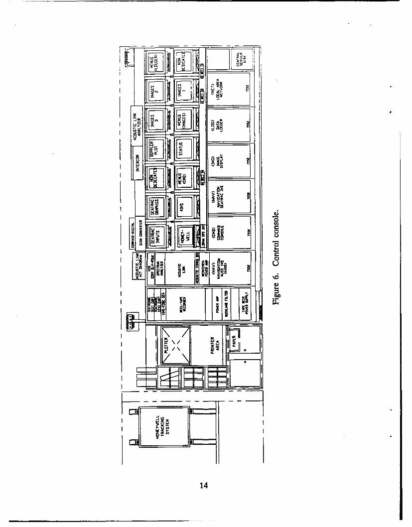
The control van is a 40-foot-long, converted cargo container that has been air con-ditioned and divided into two work areas. One area includes a small work bench forelectronics repair, storage cabinets, and a table (with booth type seating) for reportwriting. The second area houses the control console and captain's chairs for theoperators, along with additional fold-out seating for seven observers. In addition to thesurface computers, the control console (figure 6) houses the peripherals to supportvehicle control, image processing, navigation, and data logging. Also housed in theconsole are a VCR and reel-to-reel recording equipment.
13
FLUI
-P I
w, EV G~ 14
Iz11 I PZ
EBEI31I
5.5V -C-
'E~~l _
14

SURFACE COMPUTERS
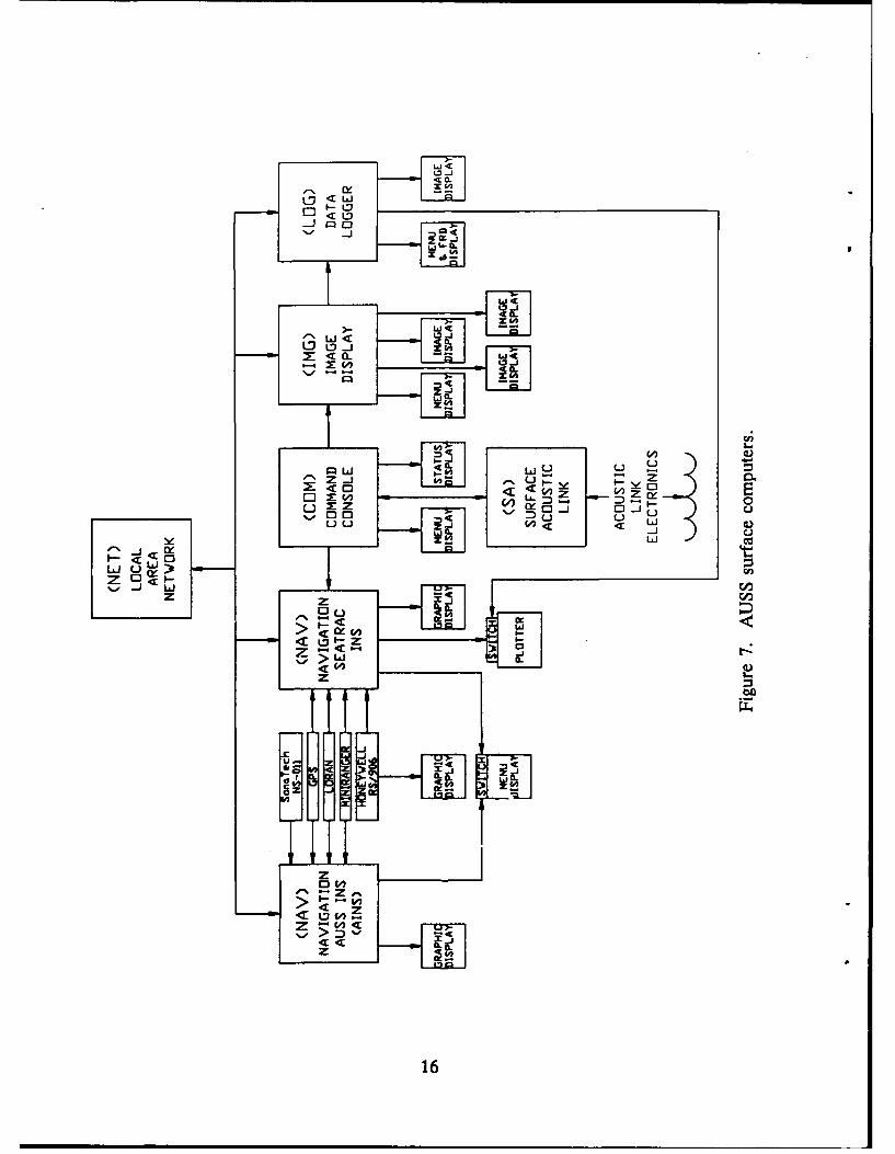
Figure 7 is a block diagram of the surface computers. The five main computers arethe AUSS Integrated Navigation System (AINS), Seatrac Integrated Navigation System(Seatrac INS), operator command (CMD), image (IMG), and the data logger (LOG).These five computers are industrial IBM 7552s modified to be AT-compatible and up-graded with either 386 or 486 system boards. These surface computers use the DOSoperating system, and their custom software is written in C. Except for the CMID,these computers are connected to a local-area network dedicated fileserver (NET) forfile sharing. The NET computer is also an IBM 7552 modified to be AT-compatibleand upgraded with a 386 system board. Software for the NET is commercial NovellAdvanced NetWare 3.11. The control van also houses the surface acoustic link comput-er (SA). The SA processor is an Intel 8085 with STD bus, and the software is writtenin PLJM.
The navigation system (NAV) includes both the AINS and Seatrac INS computers.These computers integrate the tracking information from several sources to relate theposition of the ship, vehicle, bottom transponders, and search targets in one coordinatesystem and to display these coordinates on color monitors.
The CMD computer receives all uplink data from the SA and displays status infor-mation on the vehicle status display. The CMViD also provides the menus and keyboardinterface for the vehicle operator to assemble high-level commands into the commandqueue for transmission over the acoustic link to the vehicle. All uplink and downlinkcommunications are also sent to the IMG via an RS232 link.
The IMG computer extracts vehicle sensor data and decompresses, formats, anddisplays the data as images. The IMG allows the IMG keyboard operator to manipu-late, enhance, and zoom the sensor data on the sensor displays. Nonimage data areforwarded to the LOG.
The LOG computer is designed to perform several functions. The first function isto capture all nonimage acoustic link data, uplink and downlink, and store it on thededicated fileserver. The LOG is also designed to display images stored in the file-server by the ]MG, display vehicle Doppler position, and format the vehicle flightrecorder data for display and store it in a database file. To date, only the first functionhas been performed by the LOG. Doppler position is presently being displayed on alaptop computer.
The NET links surface computers together in a local-area network and providesshared storage on a central server disk (fileserver).
The SA controls the surface acoustic link electronics. It handles all data uplink tothe surface and downlink from the surface to the vehicle.
VEHICLE CONTROL
Operator commands are input to the CMD computer using a custom AUSS key-board. This keyboard has only 45 keys and was designed to simplify vehicle operation.Two NEC MultiSync 3D monitors (MultiSync II monitors are interchangeable) are used
15
LD < Lj00
-J C:ý 0z _j
------- Li tý a. 0
C CLx
w 4ELi 0 -1
C IL0 o i xý 0-; !2 , -F Lm, 7,
Ld Anx -
Q
IL-J uM LAJ
-i -% L) 1.- 0< < <OZ V) z Ex mV) D 1.-U X z 000 D L) u uu u Z -J LLJWIL -i C.)ZO LLI0
42LLI 0 Li 0z 0
LAJ coý
z z
cn
0 L)
> I.- <
< M w
< 0 z
z> L-1.C W 0
z
.C
zxIL
OZ
z
ow- Z
> I--
< < z
z
z
16

for CMD displays. One monitor displays menus of commands to the operator, whilethe second displays vehicle status.
IMAGE PROCESSING
The IMG computer receives operator inputs through a standard 101-key keyboard.Four NEC MultiSync 3D monitors are dedicated to the 1MG. One of the monitors isused for menu display, while the other three are used to display vehicle sensor images.The control console also includes two nondedicated NEC MultiSync 3D monitors,which are normally used to display sensor images.
NAVIGATION
Each of the two NAV computers has a dedicated keyboard for operator input.These standard 101-key keyboards are used as purchased. Tracking sources common toboth computers are a MiniRanger-I (for range-range microwave tracking of the sur-face ship), and a Trimble Navigation model 1oX LORAN/GPS navigation system (fortracking the surface ship). In addition, the Seatrac INS computer receives ultrashortand long baseline tracking information from a Honeywell Marine Systems Divisionmodel RS/906 tracking system (for tracking vehicle position relative to the ship). TheAINS computer also receives long baseline tracking information from a SonaTechIncorporated model NS-011 acoustic transceiver (for tracking vehicle relative to a longbaseline network of deep-ocean transponders). Four of the monitors in the control con-sole are dedicated to navigation. Two NEC MultiSync It color monitors are used to dis-play graphic data from the AINS and Seatrac INS computers, while a third is switchedbetween AINS and Seatrac input menus. The fourth navigation monitor is a Panasonicmodel WV-5410 video monitor used to display graphic data from the Honeywell track-ing system. The control van can send duplicate navigation information to monitorslocated on the bridge of the ship. This information assists the captain in navigating theship. The control console also contains a American Graphtec Incorporated model MP4200 plotter. This plotter is connected to the Seatrac INS and is used to supply hardcopies of tracking and navigation data.
DATA LOGGING
Operator input to the LOG computer is by standard 101-key keyboard or Logitechmodel T-CA1 TrackMan mouse. Two NEC MultiSync 3D monitors are used to displayoutput from the LOG. One monitor is used to display both input menus and flightrecorder data, and the second monitor is for image playback or Doppler plots.
RECORDING EQUIPMENT
All acoustic link transmissions and select sensor images are recorded during a dive.A Sangamo Weston model Sabre 80 reel-to-reel tape recorder is used to simultaneouslyrecord the acoustic link transmissions and output from a Chrono-Log Corporation
17
series 9000 time-code generator. As desired, select sensor images can be sent from theimage monitors through a scan converter to the VCR for recording. The scan converteris a YEM Incorporated model CVS-910. The VCR is a Sony Corporation modelSLV-R5VC Super VHS recorder.
MAINTENANCE VAN
The maintenance van is also a converted cargo container. It is 30 feet long and hasbeen divided into two air-conditioned rooms. One room is large enough to allow stor-age, maintenance, and predive testing of the vehicle. Overhead hoists and specially fit-ted maintenance carts allow the maintenance personnel to open and close the vehicle,exchange the silver-zinc batteries, extract and insert the electronics chassis, and per-form most necessary maintenance and repair tasks. This maintenance area also housesthe uninterruptible power supply (UPS), battery chargers, tools, and spare parts. Therest of the van is a sealed battery room used for charging the vehicle's main batteriesand housing the UPS's standby batteries. This battery room also houses an emergencyshower and eye wash.
UPS
The UPS is used to supply surface power to the AUSS vehicle (through a DCpower supply), the surface computers, and "clean" outlets in both vans. It is aBehlman Engineering model UPS3-200-31 capable of providing up to 7500 volt-amperesof three-phase AC power at 60 Hz. When normal AC line power is available (shore orship power), the UPS isolates the load from the line anomalies, such as voltage vari-ations and transient noise. If a complete power failure occurs, or line anomalies ex-ceed tolerable limits for normal UPS operations, an automatic switch to the standbybattery supply allows the UPS to maintain an uninterrupted output. Twelve-volt, deep-cycle RV/marine batteries are used for standby power. There are four sets of five bat-teries each. Each five battery set is wired in series to supply 60 VDC to the UPS. Thefour sets of batteries are then wired in parallel to give a minimum of 1 hour of com-puter operation. The UPS is equipped with a battery charger to automatically chargethe standby batteries as needed.
MAIN BAWTERY CHARGER
AUSS uses a computer-controlled system to charge the main vehicle batteries. Thissystem includes a computer, two power supplies, cell monitor boards (see batterydescription), and custom interface electronics. The computer, cell monitor boards, andinterface electronics are used to avoid overcharging the batteries. Battery life is greatlyprolonged by monitoring the cell voltage during charge and keeping the cell from ex-ceeding a high limit. The computer is an industrial PC running custom AUSS software.The power supplies are Sytron Incorporated model SYR 150-20. Each power supply israted for 150 VDC at 20 amps. A complete description of battery charging and moni-toring can be found in NRaD TR 1539.
18

TRANSDUCER POLE
The transducer pole is an assembly made up of a long aluminum pole with twotransducers mounted to one end. One transducer is an International Transducer Corpo-ration model ITC-3185. It is used for long baseline tracking of the vehicle and surfaceship (when used in conjunction with a network of deep-ocean transponders), and actsas a backup for the acoustic link. This transducer is baffled to maximize the amountof energy radiated and received in the vertical direction and to keep surface reflectionsfrom causing secondary detects. The second transducer is a Honeywell assembly that isused for long and short baseline tracking of the vehicle. The transducer pole can belowered into the water during operations and removed from the water during transit.The pole is of sufficient length to place the transducers below the bottom of the ship'skeel.
DESCENT STRING
A descent string assembly is used to quickly pull the vehicle to operating depthwithout using vehicle power. This assembly is made up of a descent weight, sections ofrope, a transponder, and an arresting float. The configuration of the descent string as-sembly is shown in figure 8. At the completion of a dive, the transponder and arrest-ing float are recovered.
The descent weight is an approximately 100-pound steel weight with a lifting eyefor easy attachment to the descent string. There is also a small 2-pound steel angleiron weight used to prevent line from getting tangled with the transponder. Theseweights are fabricated at NRaD and are not recoverable at the end of a dive.
The transponder is a SonaTech Incorporated Model NT-020. It is equipped with an"anchor release mechanism," which is activated to release the transponder from thedescent weights for recovery. The transponder is used for acoustically marking thestarting point of the dive and can be used to track the assembly during ascent.
The arresting float is an NRaD design and is made up of two glass balls (floats),aluminum fairings, and a strobe light. This float is used to prevent the vehicle fromhitting the ocean floor when the descent is completed, and supplies the positive buoy-ancy necessary to pull the transponder to the surface at the end of a dive. The strobelight is for nighttime recovery.
HANDLING SYSTEMS
AUSS includes shipboard equipment to handle both the AUSS vehicle and EARStowfish in conditions up to sea state 3. The vehicle handling system can move thevehicle from the maintenance van to the launcher, launch it, and then reverse thisprocess at the end of the dive. The EARS system can launch, tow, and recover thetowfish. Both of these systems work without putting divers or small boats in the water.
19

AUSS VEHICLE (neutroL)
6 ft
FLOAT (60 (kbs)
TRANSPONDER (-35 Ibos)
80-100 1.t
DESCENT WEIGHT (-100 Ibs)
Figure 8. Descent string.
20

VEHICLE HANDLING SYSTEM
The vehicle handling system includes a trolley system used to transport the AUSSvehicle between the maintenance van and launcher, a launch ramp, and a ramp trans-lationi system.
The trolley system includes two trolley assemblies, each of which is a chain hoistand vehicle saddle mounted to a custom trolley. The chain hoists are ColumbusMcKinnon Corporation series 648 with a 2000-pound lifting capacity each. These chainhoists feature a load limiter to prevent damage to the vehicle when it is pulled up intothe saddles. The saddles are custom padded aluminum weldments designed to keep thevehicle from swinging in heavy seas. The trollies ride on a system of overhead J-beamsthat run from inside the maintenance van to over the launcher. Aft of the maintenancevan, the I-beams are supported by a custom overhead structure, mounted to the top ofthe van.
The launch ramp (figure 9) is a custom aluminum structure with rollers to supportthe vehicle, a motorized capstan, and a winch-operated docking cart. The capstan is anobsolete model once manufactured by Maxwell Marine Incorporated; the docking cartwinch is a Rule Industries Incorporated model V84RE. Both the capstan and dockingcart winch are powered by the same two 12-volt RV/marine batteries housed in a bat-tery box on the launch ramp. The launch ramp is attached to the ship using a tiltable,rotatable support (fifth-wheel assembly) welded to the ship's transom. During launch,the ramp is translated aft through this fifth-wheel assembly and is tilted by gravity intothe water. The aft end of the launcher floats on the water due to buoyancy voids in itsstructure. This helps to decouple the aft end of the launch ramp from the motions ofthe ship. Once released from the ramp, gravity pulls the vehicle into the water. Duringa recovery, the vehicle's nose line is grappled, threaded through the docking cart at theaft end of the ramp, and wrapped around the capstan. The capstan is used to pull thevehicle to the launch ramp and mr.hanically mate it to the docking cart. The vehicleand docking cart are then brought up the ramp by the docking cart winch and theramp is pulled out of the water by the translation system.
The ramp translation system was designed and fabricated at NRaD. A winch withhydraulic power unit and control box is used to move a deck-mounted cable car in thefore and aft direction. The forward end of the launch ramp is cornected to this cablecar by a 8-foot-long tongue. The tongue has a universal joint on each end to allow theramp to both tilt and rotate. The custom winch includes a Sundstrand-Sauer model22-3047 fixed-displacement motor, an Ausco model 27933 fail-safe brake and a Fair-field Manufacturing Company Torque Hub (planetary gear reduction hub). The outerhousing of the Torque Hub has been modified for use as the cable drum. The launcherwinch has a remote hydraulic power unit (HPU) that can be located away from thewinch out of the weather. The main components making up the HPU are a Sundstrand-Sauer model 20-2050 variable-displacement pump directly driven by a Reuland Electricmodel B10735V-X 30HP motor. The 30-hp electric motor requires 440-volt, three-phaseship's power. The HPU is connected to the winch with hydraulic hoses. These hosescan be rerouted to the EARS winch if an HPU backup is needed. The launcher is
21

A~j
coAf~
22

operated using a manual control box. With this custom box, the pump can be startedand stopped and the launcher cable speed controlled. The control box is connected toa portable electrical cable to permit the operator to walk around the deck while con-trolling the AUSS launch and recovery.
EARS HANDLING SYSTEM
The EARS handling system includes a launcher, tow cable, and winch with HPU.The EARS submersible is lowered over the stern of the ship, into the water, and towedwith the cable. When not in use, the towfish is pulled up into a saddle that is part ofthe launcher.
The EARS launcher (figure 10) is a custom AUSS design. It includes a frameassembly, saddle, and davit with articulating sheave. The launcher frame is a steelweldment with side rails and a hinged platform. The platform can be used for towfishmaintenance or when attaching/detaching the tow cable. To facilitate launch andrecovery, the launcher is secured to the .ship's deck so that it extends over the transomseveral feet. The saddle, davit, and winch are all bolted to the frame. The davit isdesigned be rotated 360 degrees and includes a small hand winch so it can be used toplace the towfish on the ship's deck.
The electromechanical tow cable is used as purchased from Endeco Incorporated. Itis a 500-foot-long HAIRED FAIREDTM cable with stainless steel overbraid. The HairedFairing is used to reduce both cable strumming and drag.
The EARS winch with remote HPU is a SEA-MAC model SM 90DH. The winchhas been modified by NRaD to increase the drum capacity. The HPU is powered by anoptional 15-hp Lombardini model 1OLD400-2 diesel engine and is connected to thewinch with hoses. This HPU can also be used as a backup to the vehicle launcherHPU by rerouting the hydraulic hoses and connecting them to that system.
23

Figure 10. EARS launcher.
24

BIBLIOGRAPHY
Acoustic Systems, Inc. 1992. "Definition of the Advanced Unmanned Search System(AUSS) Sonar Characteristics." NRaD TN 1704 (Sep). Naval Command, Controland Ocean Surveillance Center, RDT&E Division, San Diego, CA.*
Bryant, S. B. 1979. "Advanced Unmanned Search System (AUSS) Performance Analy-sis." NOSC TR 437 (Jul). Naval Ocean Systems Center, San Diego, CA.
Cooke, M. W. 1992. "Advanced Unmanned Search System (AUSS)." NRaD TD 2348(Dec). Naval Command, Control and Ocean Surveillance Center, RDT&E Division,San Diego, CA.
Endicott, D. L. Jr., and G. R. Kuhl. 1992. "Fast Area Search System (FASS): Feasibil-ity Study Appendices." NRaD TN 1703 (Sep). Naval Command, Control and OceanSurveillance Center, RDT&E Division, San Diego, CA.*
Endicott, D. L. Jr., and G. R. Kuhl. 1992. "The Fast Area Search System (FASS): AFeasibility Study." NRaD TR 1526 (Sep). Naval Command, Control and Ocean Sur-veillance Center, RDT&E Division, San Diego, CA.
Grace, D. R. 1992. "Brownian Reber Search Theory for the Advanced UnmannedSearch System." NRaD TR 1534 (Oct). Naval Command, Control and Ocean Sur-veillance Center, RDT&E Division, San Diego, CA.
Gunderson, C. R. 1978. "Advanced Unmanned Search System (AUSS), PreliminarySearch Systems Analysis." NOSC TR 375 (Dec). Naval Ocean Systems Center,San Diego, CA.
Held, J. L. 1992. "Automatic Hovering Algorithms for the Advanced UnmannedSearch System." NRaD TR 1535 (Sep). Naval Command, Control and Ocean Sur-veillance Center, RDT&E Division, San Diego, CA.
Held, J. L. and H. B. McCrackea. 1993. "Automatic Transit Algorithms for the Ad-vanced Unmanned Search System (AUSS)." NRaD TR 1536 (Jan). NavalCommand, Control and Ocean Surveillance Center, RDT&E Division, San Diego,CA.
Jones, H. V. 1992. "Advanced Unmanned Search System (AUSS) Description." NRaDTR 1528 (Nov). Naval Command, Control and Ocean Surveillance Center, RDT&EDivision, San Diego, CA.
* NRaD Technical Notes (TNs) are working documents and do not represent an official policy statement of the NavalCommand, Control and Ocean Surveillance Center (NCCOSC), RDT&E Division (NRaD). For further information,contact the author(s).
25

Keil, T. J. 1992. "Advanced Unmanned Search System (AUSS) Deep Ocean FloorSearch Performance Computer Model: Executive Summary." NRaD TN 1702 (Sep).Naval Command, Control and Ocean Surveillance Center, RDT&E Division, SanDiego, CA.*
Kono, M. E. 1992. "Surface Computer System Architecture for the AdvancedUnmanned Search System (AUSS)." NRaD TR 1538 (Dec). Naval Command,Control and Ocean Surveillance Center, RDT&E Division, San Diego, CA.
Mackelburg, G. R., S. J. Watson, and W. D. Bryan. 1992. "Advanced UnmannedSearch System (AUSS) Acoustic Communication Link Development." NRaD TR1531 (Nov). Naval Command, Control and Ocean Surveillance Center, RDT&EDivision, San Diego, CA.
McCracken, H. B. 1992. "Advanced Unmanned Search System (AUSS) SupervisoryCommand, Control and Navigation." NRaD TR 1533 (Nov). Naval Command, Con-trol, and Ocean Surveillance Center, RDT&E Division, San Diego, CA.
Osborne, P. D., and C. C. Geurin. 1992. "Advanced Unmanned Search System(AUSS) Surface Navigation, Underwater Tracking, and Transponder Network Cali-bration." NRaD TR 1532 (Oct). Naval Command, Control and Ocean SurveillanceCenter, RDT&E Division, San Diego, CA.
Rasmussen, M. E. 1992. "Advanced Unmanned Search System (AUSS) Battery Moni-tor/Charging Systems." NRaD TR 1539 (Sep). Naval Command, Control and OceanSurveillance Center, RDT&E Division, San Diego, CA.
Schwager, M., and J. Stangle (SAIC). 1992. "Advanced Unmanned Search System(AUSS) Software Description: Vol I Surface SW/Vol II Vehicle SW." NRaD TN1705 (Dec). Naval Command, Control and Ocean Surveillance Center, RDT&E Divi-sion, San Diego, CA.*
SEACO, Inc. 1992. "Development of the Acoustic Telemetry System." NRaD TD 2336(Sep). Naval Command, Control and Ocean Surveillance Center, RDT&E Division,San Diego, CA.
Stachiw J. D. 1984. "Graphite-Reinforced Plastic Pressure Hull for the Advanced Un-manned Search System (AUSS) (U)." NOSC TR 999 (Oct). Naval Ocean SystemsCenter, San Diego, CA.
Stachiw J. D. 1986. "Graphite-Fiber-Reinforced Plastic Pressure Hull Mod 1 for theAdvanced Unmanned Search System (AUSS)." NOSC TR 1182 (Dec). NavalOcean Systems Center, San Diego, CA.
"NRaD Technical Notes (TNs) are working documents and do not represent an official policy statement of the NavalCommand, Control and Ocean Surveillance Center (NCCOSC), RDT&E Division (NRaD). For further information,contact the author(s).
26

Stachiw J. D. 1988. "Graphite-Fiber-Reinforced Plastic Pressure Hull Mod 2 for theAdvanced Unmanned Search System (AUSS)." NOSC TR 1245 (Aug). NavalOcean Systems Center, San Diego, CA.
Uhrich, R. W., J. Walton, and S. J. Watson. 1978. "Portable Test Range and its Appli-cation to Side-Looking Sonar." NOSC TR 258 (Jan). Naval Ocean Systems Cen-ter, San Diego, CA.
Uhrich, R. W., and S. J. Watson. 1992. "Deep-Ocean Search and Inspection: AdvancedUnmanned Search System (AUSS) Concept of Operation." NRaD TR 1530 (Nov).Naval Command, Control and Ocean Surveillance Center, RDT&E Division, SanDiego, CA.
Uhrich, R. W., S. J. Watson, and G. R. Mackelburg (Eds.). 1992. "Advanced Un-manned Search System (AUSS) Surface Acoustic Link Description." NRaD TN1706 (Oct). Naval Command, Control and Ocean Surveillance Center, RDT&E Di-vision, San Diego, CA.*
Vought Corporation. 1992. "Design Analysis and Operations Research for theAdvanced Unmanned Search System (AUSS)." NRaD TD 2337 (Sep). Naval Com-mand, Control and Ocean Surveillance Center, RDT&E Division, San Diego, CA.
Walton, J. 1992. "Advanced Unmanned Search System (AUSS) At-Sea DevelopmentTest Report." NRaD TR 1537 (Dec). Naval Command, Control and Ocean Surveil-lance Center, RDT&E Division, San Diego, CA.
Walton, J. 1992. "Advanced Unmanned Search System (AUSS) Testbed: FY 1987Development Testing." NRaD TR 1525 (Nov). Naval Command, Control and OceanSurveillance Center, RDT&E Division, San Diego, CA.
Walton, J. 1992. "Advanced Unmanned Search System (AUSS) Testbed: Search Dem-onstration Testing." NRaD TR 1527 (Nov). Naval Command, Control and OceanSurveillance Center, RDT&E Division, San Diego, CA.
Walton, J. 1992. "Evolution of a Search System: Lessons Learned with the AdvancedUnmanned Search System." NRaD TR 1529 (Nov). Naval Command, Control andOcean Surveillance Center, RDT&E Division, San Diego, CA.
NRBD Technical Notes (TNs) are working documents and do not represent an official policy statement of the NavalCommand, Control and Ocean Surveillance Center (NCCOSC), RDT&E Division (NRaD). For further information,contact the author(s).
27

Form ApprovedREPORT DOCUMENTATION PAGE OMB No. 0704-0188
Public reporting burden for this collection of Intomitaion Is estimated to average 1 hour per response. including the time for reviewing InstructIonts. searching existing data sources. gathering andmaintainingthe data neeed. ndco~mpletng and reviewtng tie collection otlnformatlon. Send Commnents regarding this burden estimate oDayohrapc thl olcinc nomton. Includingauggestlionaftlrreduclngthis burden. to Washingon HeadquarteSerces. Orectoralefor IntOrfflalon Operallonsand Repoits. 12lSJefferson Davis HightwaySuite 1204, Arlington, VA 22202-43C2.and to the Office of Management and Budget Paperwourk Reducion Project (0704-0188). Washington, DO 20503.___________________
1. AGENCY USE ONLY (Leave blWV 2. REPORT DATE 3. REPORT TYPE AND DATES COVERED
INovember 1992 Final4. TITLE AND SUBTITLE 5. FUNDING NUMBERS
ADVANCED UNMANNED SEARCH SYSTEM (AUSS) DESCRIPTON AN: DN588521PE: 0603713N
6. AiJTHORe.S) PROJ. S0397H. V. Jones
7. PERFORMING ORGANIZATION NAME(S) AND ADDRESS(ES) 8. PERFORMING ORGANlIZATIONREPORT NUMBER
Naval Command, Control and Ocean Surveillance Center (NCCOSC)N alTR12RDT&E Division (NRaD) N a R12San Diego, CA 92152-5000
9. SPONSORINOJMONITORING AGENCY NAME(S) AND ADDRESS(ES) 10. SPONSORiNG/MONITORINGAGENCY REPORT NUMBER
Assistant Secretary of the NavyResearch and DevelopmentWashington, DC 20350
11. SUPPLEMENTARY NOTES
12L DISTRIBIJTioNIAVAILABILITY STATEMENT 12b. DITRIBUTIO)N CODE
.Approved for public release; distribution is unlimited.
13. ABSTRACT (Maxiinwn 200 Words)
This report describes the Advanced Unmanned Search System (AUSS), a self-propelled submersible designed to performbroad-area search and contact evaluation to depths of 20,000 feet. The system is based on a single, untethered, semiiautonomous,supervisory controlled vehicle. Without the burden of a cable, or the need to place a second vehicle in the water for target investi.gation, this system can reduce present search operation times by an order of magnitude.
14. SUB.JECT TERMS I& NUMBER OF PAGES
Advanced Unmanned Search System (AUSS) 3516. PRICE CODE
17. SECURITY CkASSIFICATIIN! 18, SECURITY CLASSIFICATION 19. SECURITY CLASSIFICTIO 20. UMITATIO OF ABSTRACTOF REP=R OF ThIS PAGE OF ABSTRACT
UNCLASSEFIED UNCLASSIFIED UNCLASSIFIED SAME AS REPORT
NIH 784401 -260660 standrdfar ~no 29MFONT)

UNCLASSIFID
21a AN"E OF RESPON&iBLE INOMOUAI. 21b.TREPHONE (iflCkhAWAMCOd*) 21c.OFFICE SYMBOL
H. V. Jones (619) 553.4872 Code 941
S.I~dU frm 298 PVOIQ
NON74"1-004=UNCLASSUFME