
Arocdimage.emnrd.state.nm.us/Imaging/FileStore/artesia/wf/....4 without a safety problem. The hose...
22
Form'3160-5 '(August 2007) UNITED STATES DEPARTMENT OF THE INTERIOR BUREAU OF LAND MANAGEMENT OCD SUNDRY NOTICES AND REPORTS ON WELLS Do not use this form for proposals to drill or to re-enter an abandoned well. Use form 3160-3 (APD) for such proposals. Ar tesi. 5. Lease Serial No. NMNM02447 FORM APPROVED OMB NO. 1004-0135 Expires: July 31, 2010 6. If Indian, Allottee or Tribe Name SUBMIT IN TRIPLICA TE - Other instructions on reverse side. 7. If Unit or CA/Agreement, Name and/or No. 1. TypeofWell E) Oil Well • Gas Well • Other 8. Well Name and No. BIG EDDY UNIT256H 2. Name of Operator BOPCO, L.P. Contact: NAOMI G O'DONNELL E-Mail: [email protected] 9. API Well No. 3a. Address P.O. BOX 2760 MIDLAND, TX 79702 3b. Phone No. (include area code) Ph: 432-683-2277 10. Field and Pool, or Exploratory HACKBERRY; BONESPRING, EAST 4. Location ofWell (Footage, Sec., T., R., M., nr Survey Description) Sec 33 T19S R31 E 1670FSL 2630FEL 32.614117 N Lat, 103.873631 W Lon 11. County or Parish, and State EDDY COUNTY COUNTY, NM 12. CHECK APPROPRIATE BOX(ES) TO INDICATE NATURE OF NOTICE, REPORT, OR OTHER DATA TYPE OF SUBMISSION TYPE OF ACTION 0 Notice of Intent • Subsequent Report • Final Abandonment Notice • Acidize • Alter Casing • Casing Repair • Change Plans • Convert to Injection • Deepen • Fracture Treat • New Construction • Plug and Abandon • Plug Back • Production (Start/Resume) • Reclamation • Recomplete. Q Temporarily Abandon • Water Disposal • Water Shut-Off • Well Integrity B Other Change to Original A PD 13. Describe Proposed or Completed Operation (clearly state all pertinent details, including estimated starting date of any proposed work and approximate duration thereof. If the proposal is to deepen directionally or recomplete horizontally, give subsurface locations and measured and true vertical depths of all pertinent markers and zones. Attach the Bond under which the work will be performed or provide the Bond No. on file with BLM/BIA. Required subsequent reports shall be filed within 30 days following completion of the involved operations. If the operation results in a multiple completion or recompletion in a new interval, a Form 3160-4 shall be filed once testing has been completed. Final Abandonment Notices shall be filed only after all requirements, including reclamation, have been completed, and the operator has determined that the site is ready for final inspection.) BOPCO, L.P. respectfully requests to change the 8 pt drilling program as attached. Accede! for record NMOCD RECEIVED" JUN 2 5 2013 N MQCDARJF5S < & SEE ATTACHED FOR CONDITIONS OF APPROVAL 14. I hereby certify that the foregoing is true and correct. Electronic Submission #210508 verified For BOPCO, L.P. Committed to AFMSS for processing Hamt(Prmtedfryped) CHRISTOPHER W GIESE by the BLM Well Information System ent to the Carlsbad by KURT SIMMONS on 06/18/2013 () Title DRILLING ENGINEER Sienature (Electronic Submission) Date 06/12/2013 ADDDAwr t it i THIS SPACE FOR FEDERAL OR STATE OFFICE USE Approved By Conditions of approval, if any, are attached. Approval of this notice does not warrant or certify that the applicant holds legal or equitable title to those rights in the subject lease which would entitle the applicant to conduct operations thereon. Title JUN ;!rj.e2013 As/Chris Wa! Office Title 18 U.S.C. Section 1001 and Title 43 U.S.C. Section 1212, make it a crime for any person knowingly and willfully to make to any depaiUnS^r^ft^ftyLIJ^ States any false, fictitious or fraudulent statements or representations as to any matter within its jurisdiction. ** OPERATOR-SUBMITTED ** OPERATOR-SUBMITTED ** OPERATOR-SUBMITTED
Transcript of Arocdimage.emnrd.state.nm.us/Imaging/FileStore/artesia/wf/....4 without a safety problem. The hose...

Form'3160-5 '(August 2007) UNITED STATES
DEPARTMENT OF THE INTERIOR BUREAU OF LAND MANAGEMENT OCD
SUNDRY NOTICES AND REPORTS ON WELLS Do not use this form for proposals to drill or to re-enter an
abandoned well. Use form 3160-3 (APD) for such proposals.
Artesi. 5. Lease Serial No. NMNM02447
FORM APPROVED OMB NO. 1004-0135 Expires: July 31, 2010
6. If Indian, Allottee or Tribe Name
SUBMIT IN TRIPLICA TE - Other instructions on reverse side. 7. If Unit or CA/Agreement, Name and/or No.
1. TypeofWell E) Oil Well • Gas Well • Other
8. Well Name and No. BIG EDDY UNIT256H
2. Name of Operator BOPCO, L.P.
Contact: NAOMI G O'DONNELL E-Mail: [email protected]
9. API Well No.
3a. Address P.O. BOX 2760 MIDLAND, TX 79702
3b. Phone No. (include area code) Ph: 432-683-2277
10. Field and Pool, or Exploratory HACKBERRY; BONESPRING, EAST
4. Location ofWell (Footage, Sec., T., R., M., nr Survey Description)
Sec 33 T19S R31 E 1670FSL 2630FEL 32.614117 N Lat, 103.873631 W Lon
11. County or Parish, and State
EDDY COUNTY COUNTY, NM
12. CHECK APPROPRIATE BOX(ES) TO INDICATE NATURE OF NOTICE, REPORT, OR OTHER DATA
TYPE OF SUBMISSION TYPE OF ACTION
0 Notice of Intent
• Subsequent Report
• Final Abandonment Notice
• Acidize
• Alter Casing
• Casing Repair
• Change Plans
• Convert to Injection
• Deepen
• Fracture Treat
• New Construction
• Plug and Abandon
• Plug Back
• Production (Start/Resume)
• Reclamation
• Recomplete.
Q Temporarily Abandon
• Water Disposal
• Water Shut-Off
• Well Integrity
B Other Change to Original A PD
13. Describe Proposed or Completed Operation (clearly state all pertinent details, including estimated starting date of any proposed work and approximate duration thereof. If the proposal is to deepen directionally or recomplete horizontally, give subsurface locations and measured and true vertical depths of all pertinent markers and zones. Attach the Bond under which the work will be performed or provide the Bond No. on file with BLM/BIA. Required subsequent reports shall be filed within 30 days following completion of the involved operations. If the operation results in a multiple completion or recompletion in a new interval, a Form 3160-4 shall be filed once testing has been completed. Final Abandonment Notices shall be filed only after all requirements, including reclamation, have been completed, and the operator has determined that the site is ready for final inspection.)
BOPCO, L.P. respectfully requests to change the 8 pt drilling program as attached.
Accede! for record NMOCD
RECEIVED" JUN 2 5 2013
N MQCDARJF5S < &
SEE ATTACHED FOR CONDITIONS OF APPROVAL
14. I hereby certify that the foregoing is true and correct. Electronic Submission #210508 verified
For BOPCO, L.P. Committed to AFMSS for processing
Hamt(Prmtedfryped) CHRISTOPHER W GIESE
by the BLM Well Information System ent to the Carlsbad by KURT SIMMONS on 06/18/2013 ()
Title DRILLING ENGINEER
Sienature (Electronic Submission) Date 06/12/2013 ADDDAwr t i t i
THIS S P A C E FOR FEDERAL OR STATE OFFICE USE
Approved By
Conditions of approval, if any, are attached. Approval of this notice does not warrant or certify that the applicant holds legal or equitable title to those rights in the subject lease which would entitle the applicant to conduct operations thereon.
Title JUN ;!rj.e2013 As/Chris Wa!
Office
Title 18 U.S.C. Section 1001 and Title 43 U.S.C. Section 1212, make it a crime for any person knowingly and willfully to make to any depaiUnS^r^ft^ftyLIJ^ States any false, fictitious or fraudulent statements or representations as to any matter within its jurisdiction.
** OPERATOR-SUBMITTED ** OPERATOR-SUBMITTED ** OPERATOR-SUBMITTED
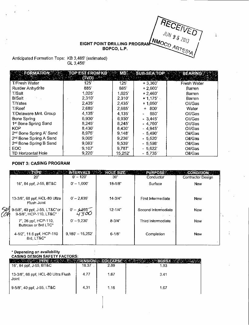
EIGHT POINT DRILLING PROGRA BOPCO, L.P.
Anticipated Formation Tops: KB 3,485' (estimated) GL 3,456'
FORMATION TOP EST FROM KB SUB-SEA TOP1
T/Fresh Water 125' + 3,360' Fresh Water Rustler Anhydrite 885' 885' + 2,600' Barren T/Salt 1,025' 1,025' + 2,460' Barren B/Salt 2,310' 2,310' + 1,175' Barren T/Yates 2,435' 2,435' + 1,050' Oil/Gas T/Reef 2,685' 2,685' + 800' Water T/Delaware Mnt. Group 4,135' 4,135' - 650' Oil/Gas Bone Spring 6,930' 6,930' - 3,445' Oil/Gas 1 s t Bone Spring Sand 8,245' 8,245' - 4,760' Oil/Gas KOP 8,430' 8,430' - 4,945' Oil/Gas 2 n d Bone Spring A' Sand 8,975' 9,148' - 5,490' Oil/Gas 2 n d Bone Spring A Sand 9,005' 9,236' - 5,520' Oil/Gas 2 n d Bone Spring B Sand 9,083' 9,539' - 5,598' Oil/Gas EOC 9,107' 9,787' - 5,622' Oil/Gas TD Horizontal Hole 9,220' 15,252' - 5,735' Oil/Gas
POINT 3: CASING PROGRAM
INTERVALS HOLE SIZE P U R P O S E , GONDITIQNi 20" 0 ' - 120' 30" Conductor Contractor Design
16", 84 ppf, J-55, BT&C 0 ' - 1,000' 18-1/8" Surface New
13-3/8", 68 ppf, HCL-80 Ultra Flush Joint
0' - 2,635' 14-3/4" First Intermediate New
9-5/8", 40 ppf, J-55, LT&C*or - 9-5/8", HCP-110, LT&C*
0' - jL£35'~T 12-1/4" Second Intermediate New
7", 26 ppf, HCP-110, Buttress or 8rd LTC*
0' - 9,230' 8-3/4" Third Intermediate New
4-1/2", 11.6 ppf, HCP-110 8rd, LT&C*
9,180'- 15,252' 6-1/8" Completion New
* Depending on availability CASING DESIGN SAFETY FACTORS:
.'TENSION' COLLAPS E?1
16", 84 ppf, J-55, BT&C 18.37 . 2.89 1.93
13-3/8", 68 ppf, HCL-80 Ultra Flush Joint
4.77 1.67 3.41
9-5/8", 40 ppf, J-55, LT&C 4.31 1.16 1.67

2
9-5/8", 40 ppf, HCP-110 6.76 2.05 3.34
Production
7", 26 ppf, HCP-110, Buttress or 8rd 3.43 1.59 1.98 LTC*
l':i6l$mplefioi#Systemr ^ ' 4-1/2", 11.6 ppf, HCP-110 8rd. LT&C 3.98 1.77 2.08
4-1/2", 11.6 ppf, HCP-110 BTC 3.02 1.66 2.08
* Depending on availability.
- INTERVAL. * < . AMT'SXS ' FTr'OF/ILU , TYPE 4 G A l i / S X ^ ' l ' , v " > 7','S
Surface:
Lead: 0' - 700' 300 700' Class C + 5% Salt + 0.7% Econolite
9.98 12.9 1.88
Tail: 700 ' -1,000 ' 220 300' Class C + 2% CACL + 0.25 LB/SK CF
6.35 14.80 1.35
Intermediate 1:
L e a d : 0 ' - 2,135' 410 2,135' EconoCem HLC +5% salt 9.32 12.90 1.85
Tail: 2,135'-2,635' 220 500' HalCem C 6.34 14.80 1.33
Intermediate 2:
Stage: 1
Tail: 2,685'-4,235' 450 1,550' HalCem C 4% bentonite + 0.6% Halad(R)-9
8.69 13.6 1.71
External Casing Packer and DV Tool @ 2,685'
Stage 2:
Lead: 0' - 2,385' 540 2,385' EconoCem HLC + NaCL 9.83 12.90 1.85
Tail: 2 ,385 ' - 2,685' 110 300' HalCem C 6.34 14.80 1.33

3
Third Intermediate/Production
Stage: 1
Lead: 5,000' - 8,430' 300 3,430' VariCem H + 0.55% Halad(R) -344
14.87 11.0 2.64
Tail: 8,430' - 9,230' 100 800' Tuned Light + 0.125 pps Poly-E-Flake
11.41 12.0 2.03
DV tool @ 5,000'
Stage: 2
Lead: 2,635'-5,000' 230 2,365' Tuned Light + 0.125 pps
Poly-E-Flake 11.70 11.0 2.35
Cement excesses will be as follows
Surface - 100% excess above gauge hole with cement circulated to surface 1 s t Intermediate - 100% excess above gauge hole with cement circulated to surface. 2 n d Intermediate - 30% excess above fluid caliper for both stages with cement circulated to surface. 3 r d Intermediate/Production - 50% excess above gauge hole with cemented circulated 50' above the Capitan reef.
Cement volumes will be adjusted proportionately for depth changes ofthe multi stage tool.
F) DIRECTIONAL DRILLING
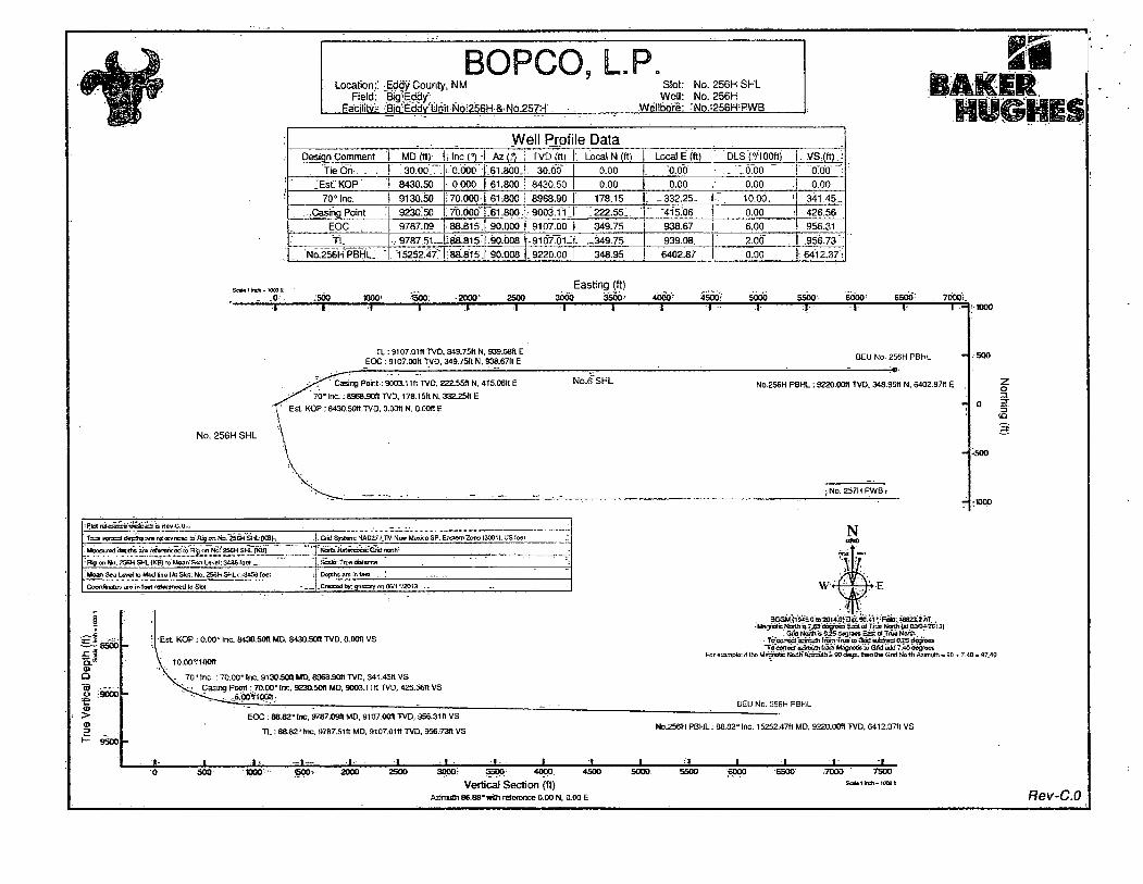
BOPCO, L.P. plans to drill out the 9-5/8" intermediate casing with a 8-3/4" bit to a TVD of approximately 8,430' at which point a directional hole will be kicked off and drilled at an azimuth of 61.80 degrees, building angle at 10.00 deg/100' to 70.0 degrees at a TVD of 8,968' (9,130' MD). This angle and azimuth will be maintained for 100' to a measured depth of approximately 9,230' (9,003' TVD). At this depth 7", 26#, HCP-110, LTC casing will be installed and cemented in two stages (DV Tool @ approximately 5000') with cement circulated 50' above the Capitan reef. A 6-1/8" open hole lateral will then be drilled out from 7" casing at an azimuth of 90.00 degrees, inclination of 88.82 degrees to a measured depth of approximately 15,252' MD (9,220' TVD). At this depth a 4-1/2" Completion System with packers installed for zone isolation will be run into the producing lateral.
G) COMPLETION SYSTEM
A 4-1/2" completion system with open hole packers will be run in the producing lateral to a depth of 15,252'. The top of the Completion System will be set at approximately 9,180' MD. Cement will not be required for this system. t\ i • /
$Pb Gr Prev!°& CA^^ -rre^ufO to>( r^remeJ^, For the 7" intermediate casing, a Cameron MBS style multibowl wellhead system will be used. After running and cementing the 7", third intermediate casing string, the BOP stack will not need to be removed in order to install the casing mandrel packoff. The mandrel packoff, lockdown screws, and wellhead to BOP flange will be tested to the full working pressure of the system at 3,000 psi. The 7" casing string will also be tested as per Onshore Order #2 prior to drilling out the shoe. The Cameron wellhead diagram is attached for reference. BOPCO, L.P. would like to request a variance to use an armored, 3", 5000 psi WP flex hose for the choke line in the drilling of the well if the rig is equip with hose. (See specification for hose that might be used, attached with APD exhibits). This is rig equipment and will help quicken nipple up time thus saving money

.4
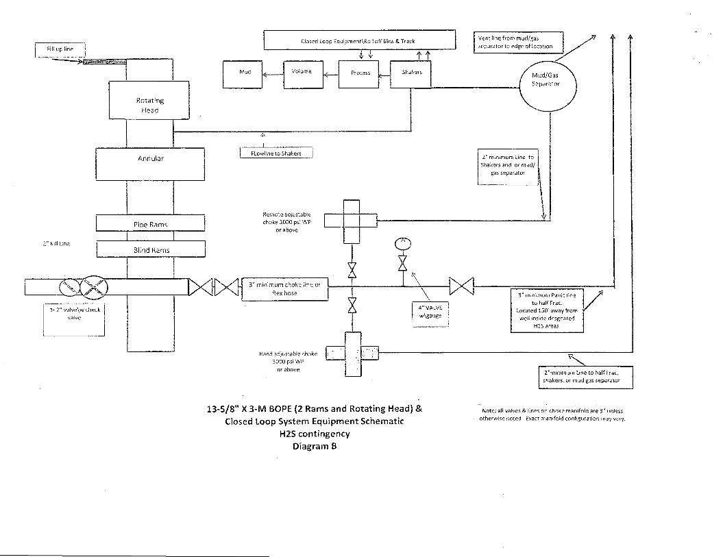
without a safety problem. The hose itself is rated to 5000 psi, and has 5000 psi flanges on each end. This well is to be drilled to approximately 15,252' MD (9,220' TVD) and max surface pressure should be +/- 2,286 psi as prescribed in Onshore Order #2 shown as max BHP minus 0.22 psi/ft. Thus, 3000 psi BOPE is all that is needed for this well. Please refer to diagrams A, B, or C for choke manifold and closed loop system layout. If an armored flex hose is utilized, the company man will have all of the proper certified paper work for that hose available on location.

7-1/16" 1.0,QQ0#
26.24
28.38
28.5"
Note: Dimensional information reflected on this drawing are estimated measurements only.
•2-1/16" 5,000#
BOPBO, LP. Well: Big Eddy Unit#256H
Conventional Wellhead Casing Design: 16" x 13.375" x9.625" x 7 " I Jeanette 6-6-13
Nanc: _u*Ui 21095943

Closed Loop Equipment\Roll off Bins & Track
Mud Volume Process Shakers *c
Process e—
FLowitne to Shakers
Hand adjustable choke 3000 psi WP
or above
3" min imum choke line or
flex hose
T
2" minimum Une to Shakers and or mud/
gas separator
4" VALVE
w\gauge
3" minimum Panic line
to half Frac. Located 100' from well
oustside designated H2S areas.
Hand adjustable choke 3000 psi WP
or above 2"minimum Line to half Frac, shakers, or mud separator
13-5/8" X 3-M BOPE (2 Rams and Rotating Head) & Closed Loop System Equipment Schematic
Diagram A
Fill up line 1
2" Kill Line
N / J ;l~ 2" va!ve\w check
valve
Closed Loop Equipment\Roii off Bins & Track
Mud Volume
Annular j
Pipe Rams
I I Blind Rams
FLowlineto Shakers
Remote adjustable choke 3000 psi WP
or above
3" minimum choke line or
flex hose
T T
CD
Vent iine from mud/gas separator to edge of location
2" minimum line to Shakers and or mud/
gas separator
-D4 4" VALVE w\gauge
3" minimum Panic line to half Frac.
Located 150' away from well inside desgnated
H2S areas.
Hand adjustable choke 3000 psi WP
or above 2"mtnimum Line to half Frac,
shakers, or mud gas separator
13-5/8" X 3-M BOPE (2 Rams and Rotating Head) &
Closed Loop System Equipment Schematic
H2S contingency
Diagram B
Note: sli valves & lines on choke manifold are 3" unless otherwise noted. Exact manifold configuration may vary.

Fill up line
M X 1 1-2" valve\w check
valve
Rotating Head
Dosed Loop £quipment\Roll off Bins & Track
4, 4-Mud Volume Process
•k ^ Process
Annular
Pipe Rams
i i Blind Rams
FLowlineto Shakers
XHXI
When H2S is present, a remotely operated choke will be installed in place of the hand adjustable choke
displayed here
Hand adjustable choke 3000 pst WP
or above
3" minimum choke line or flex hose
Hand adjustable choke 3000 psi WP
or above
CD
\
2" minimum Line to Shakers and or mud/
gas separator
1X1
DX1 4" VALVE
w\gauge
tx]
B
U
F
F
E
R
T
A
IM
K
1X1
3" minimum Panic line to half Frac.
Located 100' from well oustside designated H2S areas. Not connected to
buffer tank
Latshaw 18 additional line to Mud pits, used to bypass mud/gas separator if necessary
Latshaw 4 closed loop system, with Latshaw 18 addition "clouded."
Latshaw 13-5/8" X 3-M BOPE (2 Rams and Rotating Head) & Closed Loop System Equipment Schematic
Diagram C
Note: ail waives & lines on choke manifold are 3" unless otherwise noted. Exact manifold configuration may vary.
Sorts 1 indi -1000 (I
- - 0 '
Location:' Eddy County, NM Field: BigjEddy"
Facility? Bio-Eddv^riit N6;256H &.N6.257H
BOPCO, L.P, Slot: N0.256HSHL
Well: No. 256H Wellbore: 'No..256H ;PWB
Well Profile Data Design Comment MD (ft) - , lnc(Vl Az(3 TVD (ft) Local N (ft) Local E (ft) 'DLS'(.7100ft) VS (tt) .
"tie On.. . . 30.00 . . . 0.000 | 61.800 . 30.00" 0.00 "0.00 • . '..0.00 " O W : .'Est. KOP' 8430.50 • 0.000 I 61.800 8430.50 0.00 0.00 .0.00 0.00
70° Inc. 9130.50 ! 70.000-1 61.800 8968.90 178.15 . -332.25. '10.00. •' 341.45,: . .Casing Point 9230:50 :7O.b00T61.BO0. • 9003.111 222.55. " "415.06 0.00 426.56
EOC . 9787.09 88.815.| 90.000 9107.00 349.75 938.67 6.00 956.31 TL ,9787.51--, 588.815-1,90.008 f-9107.oi- . „349.75 939.08. .2.00 7" 956.73"
'.'No:256H^BHL." " "15252:47" . 88.815.' 90.008 . 9220.00 348.95 6402.87 0.00 : 6412.37 ;
;500 xioo' 1500. -2000' 2500 3000 Easting (ft)
3500 • 4b6o> 4500 r 5000; 5506-I 1 1 1 I i 1 • 1 I
TL EOC:
9107.01ft TVD, 349.75K N, 939.08ft E 9107.00ft TVO. 349.75ft N. 938.67ft E
6000' T—
6500 I
7000L
- r =
BEU No, 256H PBHL
' Casing Point: 9003.11ft TVD, 222.55ft N. 415.06ft E
70° Inc. :8968.90ft TVD, 178.15ft N, 332.25ft E
Est KOP : 8430.50ft TVD, O.OOft N. 0.00ft E
No .6 S H L N0.256H PSHL : 9220.00ft TVD, 348.95ft N, 6402.87ft E
No. 2S6H SHL
<a 3
; No. 257H PWB t
- Ftat T^g.-incg -tTCte^a is Rev-C.O- . . . . Tina wracal d c p f t s -.va rtfcrenCBC Jo'Rig on f io- SCHSJ-iL-pCS):. . Grid System: KAD27 /TM New Uswca SP, EasJen- Zona (3001). US lesi .'.
. Moosurad depths aro referenced to Rig an No?256H S M f (KB) • Noflh Rsi 9<rc£ca:*GrsQ nenfv
: H ^ o o h k > . » W S H L { K a f o " M o a j i " S r t . - i Lftvnl: 3186 fatrt _ . Scald: True dtstarco
.' Moan Sea l e w * la Mud fins (Ai Slot: No, 2S6H SHL): .-3456 feet . Depths aro in b*-« _• ... ,
Coordbrcftos aro ~m fost w f w w c c d to Slot - 1 . O s a a d b y . g e n t r y on 06/11/2013 . - —
~ = 8 5 0 0
fJ OJ
a "ra o c a> > <D
;9000
Es t KOP : 0.00° Inc. 8430.50ft MD. 843050ft TVD. O.OOft VS
70° Inc. : 70.00° Inc 913050ft MD. 6968.90ft TVD, 341.46ft VS Casing Point: 70.00° Inc, 9230.50(1 MO, 9003.11 ft TVD, 426.56ft VS
^6.'oo"ifiooa.
EOC : 88.62°tnc, 9787.09ft MD, 9107.00ft TVD, 956.31ft VS
TL : 88.82"Mc, 9787.51ft MD, 9107.01ft TVD, 956.73*1 VS
3CGM(19^o;»-20!«,p)t}ip:SO.'<1 V'Rotfl:.438Z3.2hT,. - fctegriatic North 'a 7.65'obsrees Eaa ot .Tha Notlh (at O3.Tli:20 13)
. : c « N d ^ o 0 ^ 3 c s i » E a a o ^ T n i * N O R . \ - '
loeomxi'sAtiiaifcaoi Magnetic id Grid add 7.40 dognses For era/opto: it [ho MaQrndc^^JiA^sntah 3flOde9s. finn Ifio Grid North Azimuth = &
BEU No. 256H PBHL
_ 1 _ 3000: 3500- 4000.
Vertical Section (ft) Aamutn 86.88*wSn reference 0.00 N, O.OO E
N0.256H PBHL: 88.82°Inc, 15252.47ft MD, 9220.00ft TVD, 5412.37ft VS
6500 .7000 7500 S<**1 <n±\- 1000 fl
Rev-C.O
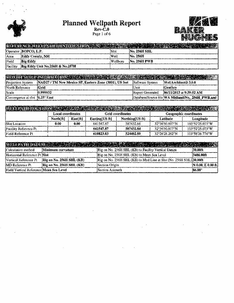
Operator BOPCO, L.P. Slot No.256HSHL Area Eddy County, NM Well No. 256H Field BigEddy Wellbore No. 256H PWB Facility Big Eddy Unit No.256H & No.257H
<V., lr* \ \. % Projection System NAD27 / TM New Mexico SP, Eastern Zone (3001), US feet Software System WellArchitect® 3.0.0 North Reference Grid User Gentbry Scale 0.999932 Report Generated 06/11/2013 at 9:39:52 AM Convergence at slot . 0.25° East Database/Source file WA Midland/No._256H_PWB,xml
L. •£ i k ^ ^ ^ h : M i & m L ^ ^ m ^ } : . . J Local coordinates Grid coordinates Geographic coordinates
Northtft] Eastfft] Easting[US ft] Northing[US ft] Latitude Longitude Slot Location 0.00 0.00 641547.87 587432.84 32°36,5.0.817"N 103°52'25.073"W Facility Reference Pt 641547.87 587432.84 32°36'50.817"N I03°52'25.073"W Field Reference Pt 610823.03 524402.80 32°26'28.262"N 103°58'26.774"W
VI - >, . >; / J V* , , s <t-Calculation method Minimum curvature Rig on No. 256H SHL (KB) to Facility Vertical Datum 30.00ft Horizontal Reference Pt Slot Rig on No. 256H SHL (KB) to Mean Sea Level 3486.00ft Vertical Reference Pt Rig on No. 256H SHL (KB) Rig on No. 256H SHL (KB) to Mud Line at Slot (No. 256H SHL)' 30.00ft MD Reference Pt Rig on No. 256H SHL (KB) Seclion Origin N 0.00, E 0.00 ft Field Vertical Reference Mean Sea Level Section Azimuth 86.88°

Wellpath Report Rev-C.O
Page 2 of 6
^Operator BOPCO. L.P. Slot No. 256H SHL
'Area Eddy County, NM Well No. 256H
Field ' ) . „ - l ! i
BigEddy Wellbore No. 256H PWB
icilily Big Eddy Unit N0.256H & No.257H
'WELLPATH: DATA'(170 stations). interpolirtcflfe

Rev-C.O Page 3 of 6
1 'Operator iBOPCO, L.P. Slot |No.256HSHL iArea 'Eddy County, NM Weil No.256H IField jBigEddy Wellbore No. 2S6H PWB 'Facility jBig Eddy Unit No.256H & No.257H

Planned Wellpath Report Rev-C.O
Page 4 of 6
l R E E E I ^ ¥ E M l ^ ^ H a l E ^ E I E l i i M f (Operator jBOPCO, L.P. iSlot No. 256H SHL
Area jEddy County, N M [Weil No. 256H
||-<ield jBigEddy [Wellbore No. 256H PWB
[Facility !Big 'Eddy Unit Np.256H & No.257H |
WEEl;p;XTH DATA (I70.statiqris) t = interpolated/extrapolated station MD | f t |
Inclination
ri Azimuth! TVD
i"i 1 Iftl Vert Sect
[ftl 1 North
Iftl East -
[ft] Grid East
|USft] Grid North; Latitude
[US ft l Longitude DLS'
I'VlOOftl Comments
8245,00+ 0.000 ,8245,00 0.00 0.00 0.00 641547.87 587432,84 j 32°36'50.8'I7"N 103n52'25.073"W .0.00 1st Bone Spring Sand 83.3,0.00+ 0.000 0.00; 0.00 . ' 0.00 641547.87 ,587432.84 ,32°36'5.0.817"N 103°52'25.073"W 0.0.0 843.0.00+ ; o.ooo '61^00" 8430:00 0.00 0.00 ; 0.00- '641547.87 587432.84 ;32o36'50.8l.7"N, 103o52'25:073!'W O.'OO 8430.50... 0.000 Woo i%0.-50- .0.00, 0.00 0:00 641547.87 587432.84 32o36,'50.8.l.7"N I03052'25.073"W ,0.00 Est. KOP
Tsa'CfboS mm llliSfSOltlll mm Lr;,., ' l i \ S i j _ i , . . . . .,
8630.007 19.950 61.800 8625.99 i 31,14 : 16.25 30.30 641578.17 [587449,09 32"36'50.976"1\T I03052'24.7I8"VY 10.0.0 8730.00+ 29.950 61.800:8716:55 j 69.301^36.16 " 67.43 641615.30 587468,99 '32°36'51,l72"'Fr 103'>52'24.,283,"W 10.00 8830.00+ 39.950 '61.800 ,8798.41 | 121.12;.' 63.19 117.85 64.1.665.71" 587496.03 32°36'5I.437"N , I03S52'23.692"W io.oo" 8930.00?
;#ptoj|| ; 49.950 g|igg|§|0
61.800 8869.09! +85.02' 96.53 180.04 641727.89 587529.37 3203"6'5i:764"N
mmm ' 103"52'22.963I"W 10.00
9l30.00t 69.950 61.800 8968:73 ' 341.02 17.7.93 331.83 ,641879.68 5876.1.0.75 32036'52,563"Ni l,03u52'2l.|84"W 10.00 9130,5.0 . 70.000 61.800 89.68.90! 341,45 178.15 . 332.25. 64188,0.09. 587610.98 32"36'52.565".N. I03°52'2I.I80"W 10.00 70" Inc. 9148.32' 70.000 61.800 8975.00 j 356.62. 186.06 ' 347.01'. 64189485 ,587618.89 3'2::36'52.643"N 103o52'2l,007"W 0.00 2nd lione Spring A Sand 9230.001 70.000 61.800 ,9002:94 426.13 222.33 414.65 64,1962.49 •587655.16 '32*36'52.999"N 103°52'20,2I4"W o.oo1
mm MM mm mm r 9236.061 70.771 62.104 |9005,00T 431.30' 225.01 J t 19.68' 641967.52 587657.84 32U36'53.025"N' IO3"52'20.i55"W, 6.00 2nd Hone Spring A Sand
933O.0.0t ' 73.135 67.152 9034.58 j513.79 263.1 v"* Jjoo.21' 642048.05 587695.99 32 < ,36'53.399"N; i03"52'J.9.2l2"W. 6.00 9430.1101; 76.422 72.352 9060.85, 605.97 296.51 590.71. 642138.54: 587729.33 32°36,53~.725"N 103°52'I8,152"W 6:00 9530.00+: 79.813 77.408 9081.45 701.64.] 322.00 . 685.1,4 642232.96 587754.82 32°36'53.973"N. I03052,I,7:047"W 6.00
908,^00] ;2693:68; n a n :t ooi 9630.00+ 83.280 82.355 9096.16 799.78 [339.35 782.47 642330.28 587772.17 r32°36'54.14,I"N; I()3052'I5.9()8"W 6.00 9730.00+ 86.796 87.233 9 i 04.81 899.29^ 348.37 881.64' 642429.45J 587781.19 32°36'54,226"N l,03''52'14.748"W 6:00 9787.09 88.815 o:ooo 9107.00 _ 956.31^
~956.73" 349.75 3497T
„ 9 3 8 - 6 L 642486.47 • 587782.57 32';36'54,237"N t'103o52 ,l4.08l"W 6.00 KOC 9787.51 i 88.815 90.008 76*7.01
_ 956.31^ ~956.73"
349.75 3497T 939.08 642486.89 587782.57 32°36'54.237"N, 103t'52,l4.076,"W 2.66" Tl..
.•52PM8 MM f6|2-52'9>3^ H'-itJi „;..!f-"ti .*?,- ]
9930.00+ ' 88.815 90.008 '9; 09.95: .1098.97 349.73 .1081.54 642629.34 ,587.782.55 32<>36'5.4.231 "N I03"52'I2.4II"VV .0,0.0
ioo3o!ooT 88.815 90.008 ,91.1,2.02; 349.72 ! 181.52. 642729.31 587782.53 i32°36'54.226"N, I03"52'I1.242"W 0.00, 10130.00+] 88.815 90.008 1 9114.09 ;f 298.63 J49.7bj 1281.50 642829.28 587782.52 . 32°36. ,54,222"N: 103°52'l 0.073 "W 0.00:
10230.00+1 88.815 90.008 "5116.16 1398.46 349.69 ; 1381.48 642929.25 "587782.50 '32<>36 l54.il7"N' I03o52'b8.905"VV 0.00
mm Mr7^2?4'9„< 10430.00+ 88.815 90.008 9120.29 1598:12 349.66, 1581.43 643129.19' 587782.47 32°36'54.208"N' los 'oe-se?' . 0.00, 10530.00+ 88.815 90.008 9122.36^ T697.95' 349:64 1681,41 643229.17. 587782T46 32°36'54.204"N I03°52:05.'398"W 0.0.0 10630.00+ 88.815 90.008 9124.43 1797.78 349.63 :i78,l.39; 64-3329.14; 587782.44 .32°36,54,,1'99"N, , i03°52'04:229"W
I0730.00t 88.815 90.008
rsoroos! i ~^r*rr ,Ti'i*:T
9126,50; f9.'l'2'8?56f
1897.6.1
WHM 349.61 1881.37- 643429.1 1 : .587782.43 32°36J54195"N'
1 S H 103"52,03.06"r'W ().()()
10930.00+ 88.815 90.008 9130.63 2097.27 '349.58 2081.33. 64.3629.05 587782.41} 32^36'54.I86"N' , r03u52,00.723"W ' 0.00 11030.00+ 88.815 90.008 9132.70.'2197.10 349.57j2i8l.3i 643729.02 ,,587782.38 32°36'54.182 "N : 103°5.r59.554"W 0.00
j 11130.00+ 88.SI5 90.008' 9134.77 2296.93 349.55, 2281,28 643829.00' 587782.37 32:'36'54.!77"N 103°5I'58.385 "W (1.00
"ii23ao67 88.815 moos' 9136.83 2396.76 349.54 1 - - . 1 . r n 1
238I..26 643928.97 587782.36 32"36'54.I73'!N. 103o5l!57;'2l7."Vy 0.00
mmm 1 1.430.00+ 88.815 90.008 9140.97 2596.42 349.51 2581.22 6441,28.91 587782.33 32U36'54.I64"N l03r'5!'54.879"W 0.00 11530.00}] 88.815 90.008 9143.04 2696.25 349.50' 268I..20 644228.88 587782.31 32°36'54.I59"N„ 103°5!'53.7lirw7 0.00 11630.00+' 88.815 90.008 9.145.10 2796.07 349.48 j278I.I8 644328.85 :587782.30 32°36'54.I5.V!N" 103V5r.52.54l"W: 0.00 1 1730.00+1 88.815 90.008 9147.17 2895.90 i349.47 J288I.I6 644428,82 587782.28 32°3654.r50"N' I03°5I'5!.372"W 0.00
JiiiWo7b S-:>r8W8iig 901008 9I^9.'24J 5995>73f3A9j5j|S98l lflf4| | 4528 |0 j •'58758221 fel$3S^ilL46|Si 3*el
";••' : !| ^.-.'.ft1™^,. ;t.*4>s£.^i . i L ^ - . , - ^ , . . - ,uJ

Rev-C.O Page 5 of 6
IgfeEE-Rl j Operator BOPCO, L.P. jSIot No. 256H SHL lArea Eddy County, NM jWell No.25611 jField BigEddy jWellbore No. 256H PWB [Facility BigEddy Unit No.256H"& No.257H j "
yyELLpATH- DATA (17.0 stations);. Incli nation I Azimuth
^f'=|iiiitci]p^

Rev-C.0 Page 6 of 6
Operator' BOPCO, L.P. Slot No.256HSHL
Area Eddy County, NM Well No.256H -
Field BigEddy Wellbore No. 256H PWB
Facility , Big Eddy Unit No.256H & No.257H
Name MD [ft]
: TVD : [ft]
North [ft]
East [ft]
Grid East [US ft]
Grid North;] Latitude [US ft]
Longitude Shape
1) B E U No. 256H PBHL 15252.47 MM . point
1) B E U No. 256H PBHL
S T O V E Y ' P R O G R A M - Hef Wellbore: No. 2S6H PWB Ref Wellpath: Rev-C.0 Start MD
m End MD
[ft] Positional Uncertainty Model Log Name/Comment Wellbore
30.00 15252.47 NaviTrak (Standard) No. 256H PWB

PECOS DISTRICT CONDITIONS OF APPROVAL
OPERATOR'S NAME: BOPCO, LP LEASE NO.: NM02447
WELL NAME & NO.: 256H-BIG EDDY UNIT SURFACE HOLE FOOTAGE: 1670' FSL & 2630' FEL
BOTTOM HOLE FOOTAGE 1980' FSL & 1505' FEL LOCATION: Section 33, T. 19 S., R 31 E„ NMPM
COUNTY: Eddy County, New Mexico
I. DRILLING
A. DRILLING OPERATIONS REQUIREMENTS
The BLM is to be notified in advance for a representative to witness:
a. Spudding well (minimum of 24 hours) b. Setting and/or Cementing of all casing strings (minimum of 4 hours) c. BOPE tests (minimum of 4 hours)
[R] Eddy County Call the Carlsbad Field Office, 620 East Greene St., Carlsbad, NM 88220, (575) 361-2822
1. Hydrogen Sulfide (H2S) monitors shall be installed prior to drilling out the surface shoe. If H2S is encountered in quantities greater than 10 PPM the well shall be shut in and H2S equipment shall be installed and flare line must be extended pursuant to Onshore Oil and Gas Order #6. After detection, the Hydrogen Sulfide area must meet Onshore Order 6 requirements, which includes equipment and personnel/public protection items.
2. Approved for drilling/skidding operation in conjunction with the Big Eddy Unit 257.
3. Floor controls are required for 3M or Greater systems. These controls will be on the rig floor, unobstructed, readily accessible to the driller and will be operational at all times during drilling and/or completion activities. Rig floor is defined as the area immediately around the rotary table; the area immediately above the substructure on which the draw works is located, this does not include the dog house or stairway area.
4. The record of the drilling rate along with the GR/N well log run from TD to surface surface (horizontal well - vertical portion of hole) shall be submitted to the BLM office as well as all other logs run on the borehole 30 days from completion. If available, a digital copy of the logs is to be submitted in addition to the paper copies.
Page 1 of 6

copies. The Rustler top and top and bottom of Salt are to be recorded on the Completion Report.
B. CASING
Changes to the approved APD casing program need prior approval if the items substituted are of lesser grade or different casing size. The Operator can exchange the components of the proposal with that of superior strength (i.e. changing from J-55 to N-80, or from 36# to 40#). Changes to the approved cement program need prior approval if the altered cement plan has less volume or strength or if the changes are substantial (i.e. Multistage tool, ECP, etc.).
Centralizers required on surface casing per Onshore Order 2.III.B.l.f.
Wait on cement (WOC) time prior to drilling out for a primary cement job will be a minimum 18 hours for a water basin, 24 hours in the potash area, or 500 pounds compressive strength, whichever is greater for all casing strings. DURING THIS WOC TIME, NO DRILL PIPE, ETC. SHALL BE RUN IN THE HOLE. Provide compressive strengths including hours to reach required 500 pounds compressive strength prior to cementing each casing string. See individual casing strings for details regarding lead cement slurry requirements.
No pea gravel permitted for remedial or fall back remedial without prior authorization from the BLM engineer.
Secretary's Potash Possible lost circulation in the Artesia Group and the Capitan Reef. Possible water flows in the Salado and Artesia Groups.
1. The 16 inch surface casing shall be set at approximately 1000 feet (a minimum of 25 feet into the Rustler Anhydrite and above the salt) and cemented to the surface. Additional cement may be required - excess calculates to 10%.
a. If cement does not circulate to the surface, the appropriate BLM office shall be notified and a temperature survey utilizing an electronic type temperature survey with surface log readout will be used or a cement bond log shall be run to verify the top of the cement. Temperature survey will be run a minimum of six hours after pumping cement and ideally between 8-10 hours after completing the cement job.
b. Wait on cement (WOC) time for a primary cement job is to include the lead cement slurry.
c. Wait on cement (WOC) time for a remedial job will be a minimum of 4 hours after bringing cement to surface or 500 pounds compressive strength,
Page 2 of 6

whichever is greater.
d. If cement falls back, remedial cementing will be done prior to drilling out that string.
2. The minimum required fill of cement behind the 13-3/8 inch intermediate casing is: (Casing is to be set above the Capitan Reef at approximately 2635')
^ Cement to surface. If cement does not circulate see B.l.a, c-d above. Wait on cement (WOC) time for a primary cement job is to include the lead cement slurry due to potash.
3. The minimum required fill of cement behind the 9-5/8 inch intermediate casing is: (Casing is to be set in the base of the Capitan Reef at approximately 4300')
a. First stage to DV tool:
53 Cement to circulate. If cement does not circulate, contact the appropriate BLM office, before proceeding with second stage cement job.
b. Second stage above first DV tool, cement shall
]K] Cement to surface. If cement does not circulate see B.l.a, c-d above. Wait on cement (WOC) time for a primary cement job is to include the lead cement slurry due to potash and Capitan Reef. Additional cement may be required - excess calculates to 23%.
Pilot hole is required to have a plug at the bottom of the hole. If two plugs are set, the BLM is to be contacted (575-361-2822) prior to tag of bottom plug, which must be a minimum of 200' in length. Operator can set one plug from bottom of pilot hole to kick-off point and save the WOC time for tagging the first plug.
4. The minimum required fi l l of cement behind the 7 inch production casing is:
c. First stage to DV tool:
5<] Cement to circulate. If cement does not circulate, contact the appropriate BLM office, before proceeding with second stage cement job.
d. Second stage above first DV tool, cement shall:
1X1 Cement should tie-back at least 50 feet above the Capitan Reef (Top of Capitan Reef estimated at 2700'). Operator shall provide method of verification.
Page 3 of 6

5. The minimum required fi l l of cement behind the 4-1/2 inch production Liner is:
/<] Cement not required - Packer/Port system to be used.
6. If hardband drill pipe is rotated inside casing, returns will be monitored for metal. If metal is found in samples, drill pipe will be pulled and rubber protectors which have a larger diameter than the tool joints of the drill pipe will be installed prior to continuing drilling operations.
C. PRESSURE CONTROL
1. All blowout preventer (BOP) and related equipment (BOPE) shall comply with well control requirements as described in Onshore Oil and Gas Order No. 2 and API RP 53 Sec. 17.
2. Variance approved to use flex line from BOP to choke manifold. Check condition of flexible line from BOP to choke manifold, replace if exterior is damaged or if line fails test. Line to be as straight as possible with no hard bends and is to be anchored according to Manufacturer's requirements. The flexible hose can be exchanged with a hose of equal size and equal or greater pressure rating. Anchor requirements, specification sheet and hydrostatic pressure test certification matching the hose in service, to be onsite for review. If the BLM inspector questions the straightness of the hose, a BLM engineer will be contacted and will review in the field or via picture supplied by inspector to determine if changes are required (operator shall expect delays if this occurs).
3. Minimum working pressure of the blowout preventer (BOP) and related equipment (BOPE) required for drilling below the surface casing shoe shall be 2000 (2M) psi.
a. For surface casing only: If the BOP/BOPE is to be tested against casing, the wait on cement (WOC) time for that casing is to be met (see WOC statement at start of casing section). Independent service company required.
4. Minimum working pressure of the blowout preventer (BOP) and related equipment (BOPE) required for drilling below the 13-3/8 inch 1 s t intermediate casing shoe shall be 3000 (3M) psi.
5. Minimum working pressure of the blowout preventer (BOP) and related equipment (BOPE) required for drilling below the 9-5/8 inch 2 n d intermediate casing shoe shall be 3000 (3M) psi.
6. Operator has proposed a multi-bowl wellhead assembly. This assembly will only be tested when installed on the 7 inch casing. Minimum working pressure of the blowout preventer (BOP) and related equipment (BOPE) required for drilling below the 7 inch casing shoe shall be 3000 (3M) psi.
Page 4 of 6

a. Wellhead shall be installed by manufacturer's representatives, submit documentation with subsequent sundry.
b. If the welding is performed by a third party, the manufacturer's representative shall monitor the temperature to verify that it does not exceed the maximum temperature of the seal.
c. Manufacturer representative shall install the test plug for the initial BOP test.
d. If the cement does not circulate and one inch operations would have been possible with a standard wellhead, the well head shall be cut off, cementing operations performed and another wellhead installed.
7. The appropriate BLM office shall be notified a minimum of 4 hours in advance for a representative to witness the tests.
a. In potash areas, for all casing strings utilizing slips, these are to be set as soon as the crew and rig are ready and any fallback cement remediation has been done. For all casing strings, casing cut-off and BOP installation can be initiated at twelve hours after bumping the plug. However, no'tests shall commence until the cement has had a minimum of 24 hours setup time.
b. The tests shall be done by an independent service company utilizing a test plug not a cup or J-packer. The operator also has the option of utilizing an independent tester to test without a plug (i.e. against the casing) pursuant to Onshore Order 2 with the pressure not to exceed 70% of the burst rating for the casing. Any test against the casing must meet the WOC time for water basin (18 hours) or potash (24 hours) or 500 pounds compressive strength, whichever is greater, prior to initiating the test (see casing segment as lead cement may be critical item).
c. The test shall be run on a 5000 psi chart for a 2-3M BOP/BOP, on a 10000 psi chart for a 5M BOP/BOPE and on a 15000 psi chart for a 10M BOP/BOPE. If a linear chart is used, it shall be a one hour chart. A circular chart shall have a maximum 2 hour clock.
d. The results of the test shall be reported to the appropriate BLM office.
e. All tests are required to be recorded on a calibrated test chart. A copy of the BOP/BOPE test chart and a copy of independent service company test will be submitted to the appropriate BLM office.
f. The BOP/BOPE test shall include a low pressure test from 250 to 300 psi. The test will be held for a minimum of 10 minutes if test is done with a test plug and 30 minutes without a test plug. This test shall be performed prior to the test at full stack pressure.
Page 5 of 6

D. DRILL STEM TEST
If drill stem tests are performed, Onshore Order 2.III.D shall be followed.
E. WASTE MATERIAL AND FLUIDS
All waste (i.e. drilling fluids, trash, salts, chemicals, sewage, gray water, etc.) created as a result of drilling operations and completion operations shall be safely contained and disposed of properly at a waste disposal facility. No waste material or fluid shall be disposed of on the well location or surrounding area.
Porto-johns and trash containers will be on-location during fracturing operations or any other crew-intensive operations.
CRW 062313
Page 6 of 6


