
· 3 HPP High pressure pumps MUNICIPALITIES MUNICIPIOS KOMMUNALTECHNIK MUNICIPALITÀ...
124
HIGH PRESSURE PUMPS GENERAL CATALOGUE EN | ES | DE | IT | FR
Transcript of · 3 HPP High pressure pumps MUNICIPALITIES MUNICIPIOS KOMMUNALTECHNIK MUNICIPALITÀ...
HIGH PRESSURE
PUMPS
GENERAL CATALOGUE
EN | ES | DE | IT | FR
2
H P P › H i g h p r e s s u r e p u m p s
3
H P P › H i g h p r e s s u r e p u m p s
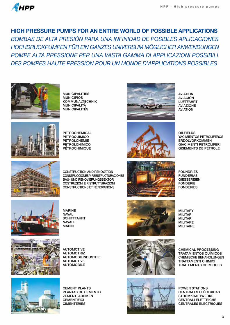
MUNICIPALITIESMUNICIPIOSKOMMUNALTECHNIKMUNICIPALITÀMUNICIPALITÉS
MARINENAVALSCHIFFFAHRTNAVALEMARIN
AUTOMOTIVEAUTOMOTRIZAUTOMOBILINDUSTRIEAUTOMOTIVEAUTOMOBILE
CEMENT PLANTSPLANTAS DE CEMENTOZEMENTFABRIKENCEMENTIFICICIMENTERIES
POWER STATIONSCENTRALES ELÉCTRICASSTROMKRAFTWERKECENTRALI ELETTRICHECENTRALES ÉLECTRIQUES
HIGH PRESSURE PUMPS FOR AN ENTIRE WORLD OF POSSIBLE APPLICATIONSBOMBAS DE ALTA PRESIÓN PARA UNA INFINIDAD DE POSIBLES APLICACIONESHOCHDRUCKPUMPEN FÜR EIN GANZES UNIVERSUM MÖGLICHER ANWENDUNGENPOMPE ALTA PRESSIONE PER UNA VASTA GAMMA DI APPLICAZIONI POSSIBILIDES POMPES HAUTE PRESSION POUR UN MONDE D’APPLICATIONS POSSIBLES
PETROCHEMICALPETROQUÍMICOPETROLCHEMIEPETROLCHIMICOPÉTROCHIMIQUE
CONSTRUCTION AND RENOVATIONCONSTRUCCIONES Y REESTRUCTURACIONESBAU- UND RENOVIERUNGSSEKTORCOSTRUZIONI E RISTRUTTURAZIONICONSTRUCTIONS ET RÉNOVATIONS
CHEMICAL PROCESSINGTRATAMIENTOS QUÍMICOSCHEMISCHE BEHANDLUNGENTRATTAMENTI CHIMICITRAITEMENTS CHIMIQUES
MILITARYMILITARMILITÄRMILITAREMILITAIRE
FOUNDRIESFUNDERÍASGIESSEREIENFONDERIEFONDERIES
OILFIELDSYACIMIENTOS PETROLÍFEROSERDÖLVORKOMMENGIACIMENTI PETROLIFERIGISEMENTS DE PÉTROLE
AVIATIONAVIACIÓNLUFTFAHRTAVIAZIONEAVIATION
4
H P P › H i g h p r e s s u r e p u m p s
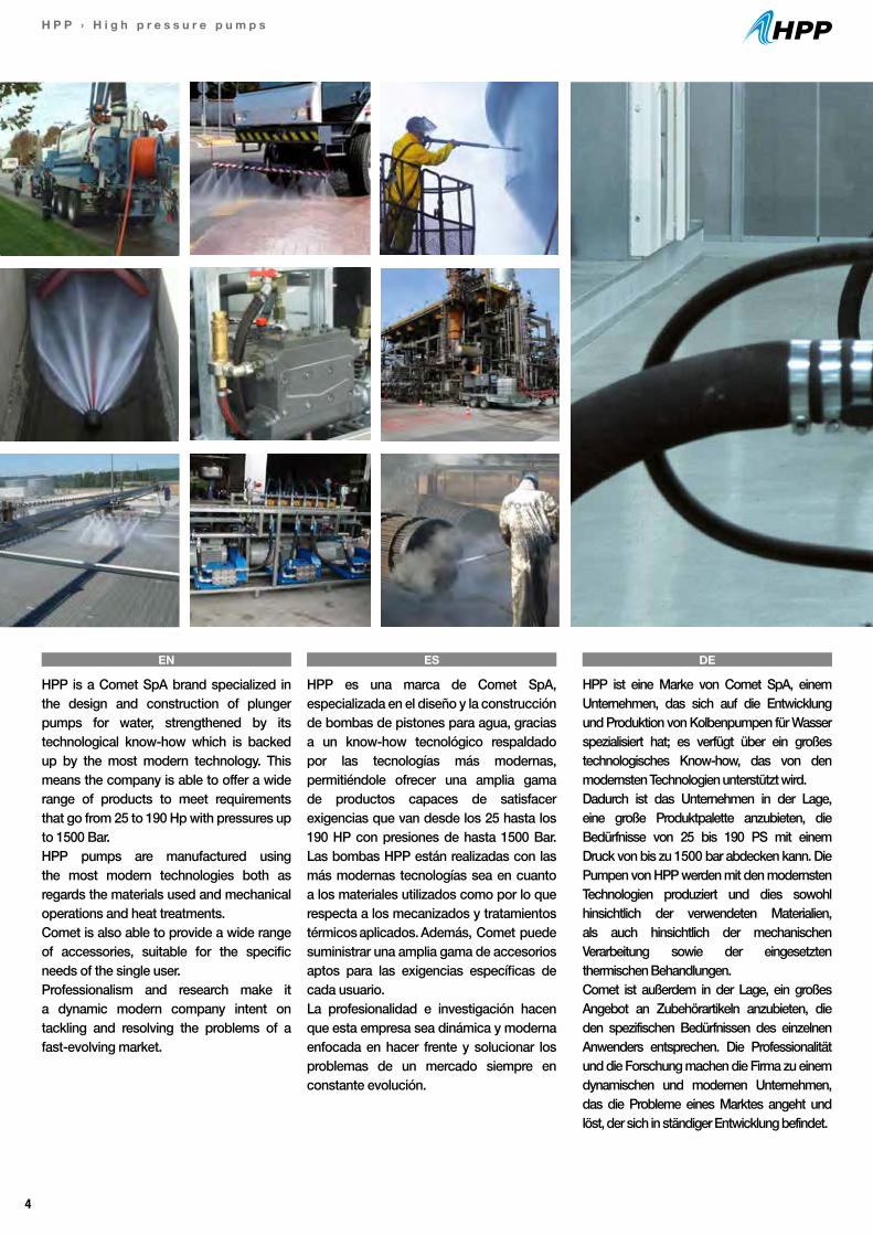
HPP is a Comet SpA brand specialized in the design and construction of plunger pumps for water, strengthened by its technological know-how which is backed up by the most modern technology. This means the company is able to offer a wide range of products to meet requirements that go from 25 to 190 Hp with pressures up to 1500 Bar.HPP pumps are manufactured using the most modern technologies both as regards the materials used and mechanical operations and heat treatments.Comet is also able to provide a wide range of accessories, suitable for the specific needs of the single user. Professionalism and research make it a dynamic modern company intent on tackling and resolving the problems of a fast-evolving market.
EN
HPP es una marca de Comet SpA, especializada en el diseño y la construcción de bombas de pistones para agua, gracias a un know-how tecnológico respaldado por las tecnologías más modernas, permitiéndole ofrecer una amplia gama de productos capaces de satisfacer exigencias que van desde los 25 hasta los 190 HP con presiones de hasta 1500 Bar. Las bombas HPP están realizadas con las más modernas tecnologías sea en cuanto a los materiales utilizados como por lo que respecta a los mecanizados y tratamientos térmicos aplicados. Además, Comet puede suministrar una amplia gama de accesorios aptos para las exigencias específicas de cada usuario. La profesionalidad e investigación hacen que esta empresa sea dinámica y moderna enfocada en hacer frente y solucionar los problemas de un mercado siempre en constante evolución.
HPP ist eine Marke von Comet SpA, einem Unternehmen, das sich auf die Entwicklung und Produktion von Kolbenpumpen für Wasser spezialisiert hat; es verfügt über ein großes technologisches Know-how, das von den modernsten Technologien unterstützt wird.Dadurch ist das Unternehmen in der Lage, eine große Produktpalette anzubieten, die Bedürfnisse von 25 bis 190 PS mit einem Druck von bis zu 1500 bar abdecken kann. Die Pumpen von HPP werden mit den modernsten Technologien produziert und dies sowohl hinsichtlich der verwendeten Materialien, als auch hinsichtlich der mechanischen Verarbeitung sowie der eingesetzten thermischen Behandlungen.Comet ist außerdem in der Lage, ein großes Angebot an Zubehörartikeln anzubieten, die den spezifischen Bedürfnissen des einzelnen Anwenders entsprechen. Die Professionalität und die Forschung machen die Firma zu einem dynamischen und modernen Unternehmen, das die Probleme eines Marktes angeht und löst, der sich in ständiger Entwicklung befindet.
ES DE
5
H P P › H i g h p r e s s u r e p u m p s
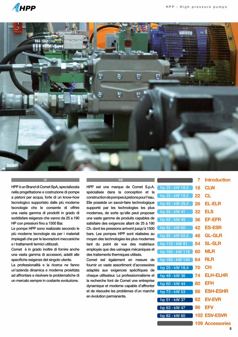
HPP est une marque de Comet S.p.A. spécialisée dans la conception et la construction de pompes à pistons pour l’eau. Elle possède un savoir-faire technologique supporté par les technologies les plus modernes, de sorte qu’elle peut proposer une vaste gamme de produits capables de satisfaire des exigences allant de 25 à 190 Ch. dont les pressions arrivent jusqu’à 1500 bars. Les pompes HPP sont réalisées au moyen des technologies les plus modernes tant du point de vue des matériaux employés que des usinages mécaniques et des traitements thermiques utilisés.Comet est également en mesure de fournir un vaste assortiment d’accessoires adaptés aux exigences spécifiques de chaque utilisateur. Le professionnalisme et la recherche font de Comet une entreprise dynamique et moderne capable d’affronter et de résoudre les problèmes d’un marché en évolution permanente.
HPP è un Brand di Comet SpA, specializzata nella progettazione e costruzione di pompe a pistoni per acqua, forte di un know-how tecnologico supportato dalle più moderne tecnologie che le consente di offrire una vasta gamma di prodotti in grado di soddisfare esigenze che vanno da 25 a 190 HP con pressioni fino a 1500 Bar.Le pompe HPP sono realizzate secondo le più moderne tecnologie sia per i materiali impiegati che per le lavorazioni meccaniche e i trattamenti termici utilizzati.Comet è in grado inoltre di fornire anche una vasta gamma di accessori, adatti alle specifiche esigenze del singolo utente.La professionalità e la ricerca ne fanno un’azienda dinamica e moderna proiettata ad affrontare e risolvere le problematiche di un mercato sempre in costante evoluzione.
IT FR 718222632364248546064707480869296102109
IntroductionCLWCLEL-ELRELSEF-EFRES-ESR GL-GLRSL-SLRMLRRLRCHELH-ELHREFHESH-ESHREV-EVREFVESV-ESVRAccessories
hp 25 › kW 18,5
hp 25 › kW 18,5
hp 40 › kW 29,4
hp 55 › kW 41
hp 62 › kW 45
hp 82 › kW 60
hp 85 › kW 62,5
hp 110 › kW 81
hp 160 › kW 118
hp 190 › kW 140
hp 25 › kW 18,4
hp 49 › kW 36
hp 60 › kW 44
hp 73 › kW 53
hp 51 › kW 37
hp 63 › kW 47
hp 82 › kW 60
6
H P P › H i g h p r e s s u r e p u m p s
EfficiencyThe HPP plunger pumps fall within the category of the reciprocating positive displacement plun-ger pumps, i.e., with technical specifications whereby liquid flow occurs by virtue of the va-riations of one or more capacities which, alter-nately, suctions and delivers the liquid. The dif-ference between the maximum and minimum volume of the variable capacity represents the theoretical volume of pumped liquid. The HPP plunger pumps are of the Triplex type, i.e., they feature three pumping elements, arranged with parallel axes lying on a same horizontal plane.The pumps are essentially made up of two fun-damental constructive elements, assembled in a fixed way the one to the other:- the mechanical part (Gear-End) which com-prises the crankcase and internal parts (oil bath) which serves to move the pump.- the hydraulic part (Fluid End) which comprises the pump head and elements in contact with the liquid to be pumped.
PrestazioniLe pompe a pistoni HPP rientrano nella cate-goria delle pompe volumetriche alternative a pistoni, cioè dotate di caratteristiche tecniche per cui lo scorrimento del liquido avviene in virtù delle variazioni di una o più capacità che, al-ternativamente, aspirano e mandano il liquido. La differenza fra volume massimo e mi-nimo della capacità variabile rappresenta il volume teorico di liquido pompato. Le pompe a pistoni HPP sono di tipo Triplex, cioè sono strutturate su tre elementi pompanti, disposti ad assi paralleli giacenti su uno stesso pia-no orizzontale. Le pompe sono essenzialmente composte da due elementi costruttivi fonda-mentali, assemblati in modo fisso tra loro: - la parte meccanica (Gear-End) che comprende il carter e gli organi interni (in bagno d’olio) che hanno la funzione del movimento della pompa. - la parte idraulica (Fluid-End) che comprende la Testata e gli elementi a contatto con il liquido da pompare.
PerformancesLes pompes à pistons HPP font partie de la catégorie des pompes volumétriques alterna-tives à pistons, c’est-à-dire qu’elles possèdent des caractéristiques techniques telles que le déplacement du liquide s’effectue en fonction des variations d’une ou plusieurs capacités qui, alternativement, aspirent et refoulent le liquide.La différence entre volume maximum et mini-mum de la capacité variable représente le vo-lume théorique de liquide pompé. Les pompes à pistons HPP sont de type Triplex, c’est-à-dire qu’elles sont structurées sur trois éléments de pompage, disposés en axes parallèles placés sur un même plan horizontal. Les pompes sont principalement composées de deux éléments de construction fondamentaux, assemblés de façon fixe entre eux :- la partie mécanique (Gear-End) qui comprend le carter et les autres pièces internes (en bain d’huile), qui assurent le mouvement de la pompe.- la partie hydraulique (Fluid-End) qui comprend la tête et les éléments au contact du liquide à pomper.
PrestacionesLas bombas de pistones HPP forman parte de la categoría de bombas volumétricas alternativas de pistones, es decir, dotadas de características técnicas por lo cual el desplazamiento del líquido se produce en virtud de las variaciones de una o más capacidades, que aspiran e impulsan el líquido alternativamente. La diferencia entre volu-men máximo y mínimo de la capacidad variable representa el volumen teórico de líquido bombe-ado. Las bombas de pistones HPP son de tipo Triplex, es decir, están estructuradas sobre tres elementos bombeantes, dispuestos en ejes pa-ralelos que yacen en el mismo plano horizontal.Las bombas están formadas esencialmente pordos elementos constructivos fundamentales, ensamblados entre sí de forma fija:- la parte mecánica (Gear-End) que incluye el cárter y los órganos internos (en baño de aceite) cuya función es mover la bomba.- la parte hidráulica (Fluid-End) que incluye el ca-bezal y los elementos a contacto con el líquido por bombear.
Parte mecánica (Gear-End)
La Parte mecánica incluye los órganos que pro-ducen el movimiento de los elementos bombe-antes de la bomba. Cada elemento bombeante incluye un pistón (a su vez constituido por un “pistón de guía” y un “pistón bombeante”, coa-xiales y solidarios entre sí) al cual se suministra el movimiento alternativo, responsable de las acciones de aspiración y de presión. El movi-miento alternativo del pistón lo proporciona un
Mechanical part (Gear-End)
The mechanical part comprises the parts that produce the movement of the pumping ele-ments of the pump. Each pumping element comprises a piston (in turn made up of a “drive piston” and a “pumping piston”, coaxial and integral with each other) to which the recipro-cating motion is provided that produces the suction and pressure actions. The reciprocating motion of the piston is produced by a connec-
LeistungenDie Kolbenpumpen von HPP gehören in die Kategorie der alternierenden volumetrischen Kolbenpumpen, d.h. dass sie über technische Eigenschaften verfügen, aufgrund deren das Fließen der Flüssigkeit durch die Variationen einer oder mehrerer Kräfte erfolgt, die die Flüs-sigkeit alternierend ansaugen und auslassen. Der Unterschied zwischen dem Höchst- und Mindestvolumen der variablen Leistung stellt das theoretische Volumen der gepumpten Flüs-sigkeit dar. Die Kolbenpumpen von HPP sind Triplex-Kolbenpumpen, d.h., dass sie aus drei Pumpenelementen aufgebaut sind, die auf Pa-rallelachsen angeordnet sind, die auf derselbenhorizontalen Fläche liegen. Die Pumpen beste-hen im Wesentlichen aus zwei Grundbauele-menten, die fest zusammengebaut sind:- dem mechanischen Teil (Gear-End), der das Ge-häuse und die inneren Elemente umfasst (im Ölbad), die die Funktion der Bewegung der Pumpe haben.- dem hydraulischen Teil (Fluid-End), der den Kopf und die Elemente umfasst, die in Kontakt mit der zu pumpenden Flüssigkeit sind.
Der mechanische Teil (Gear-End)
Der mechanische Teil umfasst die Elemente, die die Bewegung der Pumpenelemente der Pumpe erzeugen. Jedes Pumpenelement umfasst einen Kolben (der wiederum aus einem „Führungskol-ben“ und einem „Pumpkolben“ zusammengesetzt ist, die koaxial und fest miteinander verbunden sind), auf den die alternierende Bewegung über-tragen wird, die für das Ansaugen und den Druck verantwortlich ist. Die alternierende Bewegung
EN
EN
IT FR
ES
ES
DE
DE
HPP HIGH PRESSURE PUMPS - OPERATION AND COMPOSITIONBOMBAS DE ALTA PRESIÓN HPP - FUNCIONAMIENTO Y COMPOSICIÓNHPP HOCHDRUCKPUMPEN - BETRIEB UND AUFBAUPOMPE AD ALTA PRESSIONE HPP - FUNZIONAMENTO E COMPOSIZIONEPOMPES HAUTE PRESSION HPP - FONCTIONNEMENT ET COMPOSITION
7
H P P › H i g h p r e s s u r e p u m p s
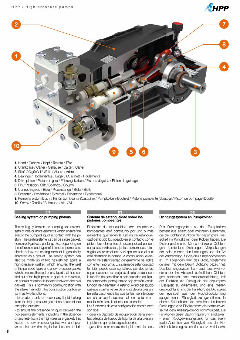
Parte idraulica (Fluid-End)La Parte idraulica della pompa comprende la testata, i pistoni pompanti, il sistema di tenuta e le valvole di aspirazione e mandata.Il pistone pompante delle pompe HPP è di tipo “tuffante”, ovvero il sistema di tenuta del liquido pompato è fisso, mentre il pistone scorre al suo interno.Il pistone pompante può essere realizzato con una bussola, in materiale ceramico, applicata al pistone di guida e trattenuta da una vite, op-pure con un pistone integrale in materiale ad elevata durezza applicato direttamente sul pi-stone di guida. Sul pistone pompante agisce il sistema di tenuta, con la funzione di garantire la tenuta del liquido pompato durante lo scorri-mento alternativo del pistone pompante.Nell’immagine che segue è rappresentata una possibile configurazione della pompa HPP.
Partie hydraulique (Fluid-End)La partie hydraulique de la pompe comprend la tête, les pistons de pompage, le système d’étanchéité et les soupapes d’aspiration et de refoulement.Le piston de pompage des pompes HPP est de type «plongeant», c’est-à-dire que le système d’étanchéité du liquide pompé est fixe, tandis que le piston coulisse à l’intérieur.Le piston de pompage peut être réalisé avec une douille en matériau céramique, appliquée au piston de guidage et fixée par une vis, ou avec un piston intégral dans un matériau très dur appliqué directement sur le piston de gui-dage. Sur le piston de pompage agit le système d’étanchéité, avec la fonction d’assurer l’étan-chéité du liquide pompé pendant le coulisse-ment alternatif du piston de pompage.Sur l’image ci-dessous est représentée une configuration possible de la pompe HPP.
Parte hidráulica (Fluid-End)La Parte hidráulica de la bomba incluye el ca-bezal, los pistones bombeantes, el sistema de estanqueidad y las válvulas de aspiración e impulsión. La bomba HPP de pistones prevé el sistema de estanqueidad del líquido bombe-ado de tipo fijo, mientras el pistón se desplaza en su interior. El pistón bombeante se puede realizar con un casquillo, de material cerámico, aplicado al pistón de guía y sostenido por un tornillo, o bien con un pistón integral en material de alta dureza, directamente aplicado al pistón de guía. En el pistón bombeante interviene el sistema de estanqueidad, cuya función es ga-rantizar la estanqueidad del líquido bombeado durante el deslizamiento alternativo del pistón bombeante. En la imagen siguiente se represen-ta una posible configuración de la bomba HPP.
sistema de biela-manivela, conectado al pistón de guía a través de un pasador y movido por una de las tres excéntricas (desfasadas 120° entre sí) de un eje. El eje está sostenido por al menos dos rodamientos y tiene una extre-midad que sobresale del cárter para tomar el movimiento del motor que acciona la bomba, directamente o a través de un reductor de re-voluciones.
Hydraulic part (Fluid-End)The hydraulic part of the pump comprises the head, the pumping pistons, the sealing system and the suction/delivery valves.The pumping piston of the HPP pumps is of the “plunger” type, i.e., the pumped liquid sealing system is fixed, while the piston slides inside. The pumping piston can be made with a bush, in ceramic material, fitted to the drive piston and retained by a screw, or with an integral piston made of very hard material fitted directly on the drive piston. The sealing system acts on the pumping piston to ensure the seal of the pum-ped liquid during the reciprocating sliding of the pumping piston. The following image shows a possible configuration of the HPP pump.
ting rod-crank system connected to the drive piston by means of a pin and moved by one of the three eccentrics (offset the one to the other by 120°) of a shaft. The shaft is supported by at least two bearings and one of its ends protru-des from the crankcase to get its motion from the motor driving the pump, directly or through a gearbox.
Parte meccanica (Gear-End)La Parte meccanica comprende gli organi che generano il movimento degli elementi pompanti della pompa. Ogni elemento pompante com-prende un pistone (composto a sua volta da un“pistone di guida” ed un “pistone pompan-te”, coassiali e solidali tra loro) a cui viene forni-to il movimento alternativo, responsabile delle azioni di aspirazione e di pressione. Il movimento alternativo del pistone è dato da un sistema biella-manovella, collegato al pisto-ne di guida tramite uno spinotto e mosso da uno dei tre eccentrici (sfasati tra loro di 120°) di un albero. L’albero è supportato da almeno due cuscinetti e ha una estremità che fuoriesce dal carter per prendere il moto dal motore che aziona la pompa, direttamente o tramite un ri-duttore di giri.
Partie mécanique (Gear-End)La partie mécanique comprend les éléments qui entraînent le mouvement des éléments de pompage de la pompe. Chaque élément de pompage comprend un piston (composé à son tour d’un « piston de guidage » et d’un « piston de pompage », coaxiaux et reliés entre eux) auquel est fourni le mouvement alternatif, à l’origine des actions d’aspiration et de pression.Le mouvement alternatif du piston est engendré par un système bielle-manivelle, relié au piston de guidage au moyen d’un goujon et actionné par l’un des trois excentriques (décalés entre eux de 120°) d’un arbre. L’arbre est soutenu par deux roulements minimum et présente une extrémité qui sort du carter, pour s’atteler au moteur qui actionne la pompe, directement ou par l’intermédiaire d’un réducteur de rotation.
Hydraulischer Teil (Fluid-End)Der hydraulische Teil der Pumpe umfasst den Kopf, die Pumpkolben, das Dichtungssystem und die Ansaug- und Auslassventile. Der Pumpkolben der Pumpen von HPP ist ein “Plunger”-Kolben bzw. das Dichtungssystem der gepumpten Flüssigkeit ist fest, während der Kolben sich in seinem Inneren bewegt. Der Pumpkolben kann mit einer Buchse aus Keramikmaterial hergestellt sein, die an den Führungskolben angebracht und von einer Schraube gehalten wird, oder mit einem Integralkolben aus besonders hartem Material, der direkt am Führungskolben angebracht ist. Auf den Pumpkolben wirkt das Dichtungssystem mit der Funktion, die Dichtigkeit der gepumpten Flüs-sigkeit während der alternierenden Bewegung des Pumpkolbens zu gewährleisten. Auf der fol-genden Abbildung wird eine mögliche Konfigurie-rung der Pumpe von HPP gezeigt.
des Kolbens ergibt sich aus einem Pleuelstangen-Kurbel-System, das mit dem Führungskolben mit einem Stift verbunden ist und von einem der drei Exzenter (untereinander mindestens um 120° phasenverschoben) einer Welle bewegt wird. Die Welle wird durch mindestens zwei Lager ge-stützt und hat ein Ende, das aus dem Gehäuse herausragt, um die Bewegung vom Motor, der die Pumpe bewegt, direkt oder mittels eine Unter-setzungsgetriebes zu empfangen.
EN
IT
IT
FR
FR
ES DE
8
H P P › H i g h p r e s s u r e p u m p s
359 610
4
7
8
2
1
1. Head / Cabezal / Kopf / Testata / Tête2. Crankcase / Cárter / Gehäuse / Carter / Carter3. Shaft / Cigüeñal / Welle / Albero / Arbre4. Bearings / Rodamientos / Lager / Cuscinetti / Roulements5. Drive piston / Pistón de guía / Führungskolben / Pistone di guida / Piston de guidage6. Pin / Pasador / Stift / Spinotto / Goujon7. Connecting rod / Biela / Pleuelstange / Biella / Bielle8. Eccentric / Excéntrica / Exzenter / Eccentrico / Excentrique9. Pumping piston (Bush) / Pistón bombeante (Casquillo) / Pumpkolben (Buchse) / Pistone pompante (Bussola) / Piston de pompage (Douille)10. Screw / Tornillo / Schraube / Vite / Vis
Sealing system on pumping pistons
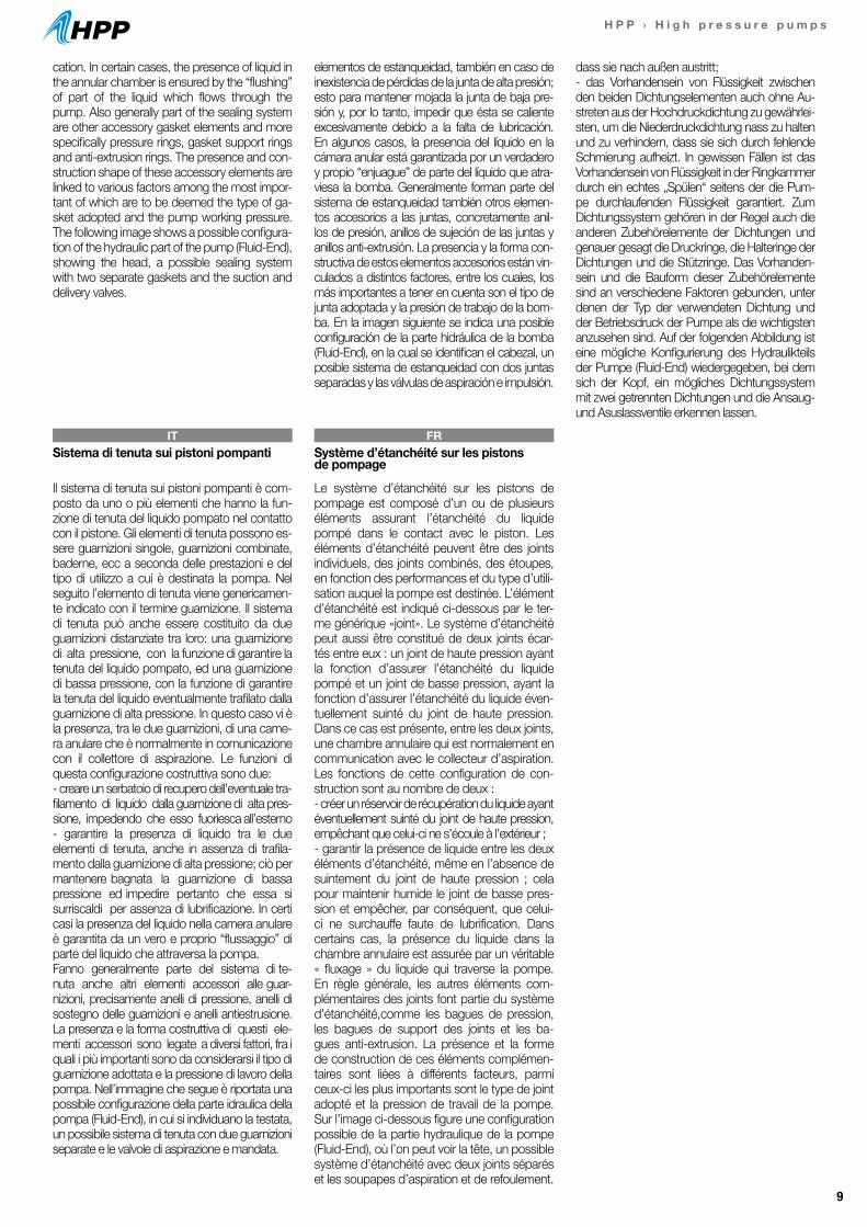
The sealing system on the pumping pistons con-sists of one or more elements which ensure the seal of the pumped liquid in contact with the pi-ston. The sealing elements can be single gasket, combined gaskets, packing, etc., depending on the efficiency and type of intended pump use. Herein below, the sealing element is generically indicated as a gasket. The sealing system can also be made up of two gaskets set apart: a high-pressure gasket, which ensures the seal of the pumped liquid and a low-pressure gasket which ensures the seal of any liquid that has lea-ked out of the high-pressure gasket. In this case, an annular chamber is located between the two gaskets. This is normally in communication with the intake manifold. This construction configura-tion has two functions: - to create a tank to recover any liquid leaking from the high-pressure gasket and prevent this escaping outside;- to ensure the presence of liquid between the two sealing elements, including in the absence of any leak from the high-pressure gasket; this keeps the low-pressure gasket wet and pre-vents it from overheating in the absence of lubri-
Sistema de estanqueidad sobre los pistones bombeantes
El sistema de estanqueidad sobre los pistones bombeantes está constituido por uno o más elementos que tienen la función de estanquei-dad del líquido bombeado en el contacto con el pistón. Los elementos de estanqueidad pueden ser juntas invididuales, juntas combinadas, etc., según las prestaciones y el tipo de uso al cual está destinado la bomba. A continuación, el ele-mento de estanqueidad generalmente se indica con el término junta. El sistema de estanqueidad también puede estar constituido por dos juntas separadas entre sí: una junta de alta presión, con la función de garantizar la estanqueidad del líqui-do bombeado, y otra junta de baja presión, con la función de garantizar la estanqueidad del líquido que eventualmente pierde la junta de alta presión. En esta caso, entre las dos juntas, se interpone una cámara anular que normalmente está en co-municación con el colector de aspiración. Las funciones de esta configuración constructiva son dos:- crear un depósito de recuperación de la even-tual pérdida de líquido de la junta de alta presión, impidiendo que éste salga al exterior;- garantizar la presencia de líquido entre los dos
Dichtungssystem an Pumpkolben
Das Dichtungssystem an den Pumpkolben besteht aus einem oder mehreren Elementen, die die Dichtungsfunktion der gepumpten Flüs-sigkeit im Kontakt mit dem Kolben haben. Die Dichtungselemente können einzelne Dichtun-gen, kombinierte Dichtungen, Verpackungen etc. sein, je nach den Leistungen und der Art der Verwendung, für die die Pumpe vorgesehen ist. Im Folgenden wird das Dichtungselement generell mit dem Begriff Dichtung bezeichnet. Das Dichtungssystem kann auch aus zwei vo-neinander im Abstand befindlichen Dichtun-gen bestehen: eine Hochdruckdichtung, mit der Funktion die Dichtigkeit der gepumpten Flüssigkeit zu garantieren, und eine Nieder-druckdichtung, mit der Funktion, die Dichtigkeit der eventuell aus der Hochdruckdichtung ausgetretenen Flüssigkeit zu garantieren. In diesem Fall befindet sich zwischen den beiden Dichtungen eine Ringkammer, die normalerwei-se mit dem Ansaugkollektor kommuniziert. Die Funktionen dieser Baukonfigurierung sind zwei:- einen Rückgewinnungstank für das even-tuelle Austreten von Flüssigkeit aus der Ho-chdruckdichtung zu schaffen und zu verhindern,
EN ES DE
9
H P P › H i g h p r e s s u r e p u m p s
dass sie nach außen austritt;- das Vorhandensein von Flüssigkeit zwischen den beiden Dichtungselementen auch ohne Au-streten aus der Hochdruckdichtung zu gewährlei-sten, um die Niederdruckdichtung nass zu halten und zu verhindern, dass sie sich durch fehlende Schmierung aufheizt. In gewissen Fällen ist das Vorhandensein von Flüssigkeit in der Ringkammer durch ein echtes „Spülen“ seitens der die Pum-pe durchlaufenden Flüssigkeit garantiert. Zum Dichtungssystem gehören in der Regel auch die anderen Zubehörelemente der Dichtungen und genauer gesagt die Druckringe, die Halteringe der Dichtungen und die Stützringe. Das Vorhanden-sein und die Bauform dieser Zubehörelemente sind an verschiedene Faktoren gebunden, unter denen der Typ der verwendeten Dichtung und der Betriebsdruck der Pumpe als die wichtigsten anzusehen sind. Auf der folgenden Abbildung ist eine mögliche Konfigurierung des Hydraulikteils der Pumpe (Fluid-End) wiedergegeben, bei dem sich der Kopf, ein mögliches Dichtungssystem mit zwei getrennten Dichtungen und die Ansaug-und Asuslassventile erkennen lassen.
Sistema di tenuta sui pistoni pompanti
Il sistema di tenuta sui pistoni pompanti è com-posto da uno o più elementi che hanno la fun-zione di tenuta del liquido pompato nel contatto con il pistone. Gli elementi di tenuta possono es-sere guarnizioni singole, guarnizioni combinate, baderne, ecc a seconda delle prestazioni e del tipo di utilizzo a cui è destinata la pompa. Nel seguito l’elemento di tenuta viene genericamen-te indicato con il termine guarnizione. Il sistema di tenuta può anche essere costituito da due guarnizioni distanziate tra loro: una guarnizione di alta pressione, con la funzione di garantire la tenuta del liquido pompato, ed una guarnizione di bassa pressione, con la funzione di garantire la tenuta del liquido eventualmente trafilato dalla guarnizione di alta pressione. In questo caso vi è la presenza, tra le due guarnizioni, di una came-ra anulare che è normalmente in comunicazione con il collettore di aspirazione. Le funzioni di questa configurazione costruttiva sono due:- creare un serbatoio di recupero dell’eventuale tra-filamento di liquido dalla guarnizione di alta pres-sione, impedendo che esso fuoriesca all’esterno- garantire la presenza di liquido tra le due elementi di tenuta, anche in assenza di trafila-mento dalla guarnizione di alta pressione; ciò per mantenere bagnata la guarnizione di bassa pressione ed impedire pertanto che essa si surriscaldi per assenza di lubrificazione. In certi casi la presenza del liquido nella camera anulare è garantita da un vero e proprio “flussaggio” di parte del liquido che attraversa la pompa.Fanno generalmente parte del sistema di te-nuta anche altri elementi accessori alle guar-nizioni, precisamente anelli di pressione, anelli di sostegno delle guarnizioni e anelli antiestrusione. La presenza e la forma costruttiva di questi ele-menti accessori sono legate a diversi fattori, fra i quali i più importanti sono da considerarsi il tipo di guarnizione adottata e la pressione di lavoro della pompa. Nell’immagine che segue è riportata una possibile configurazione della parte idraulica della pompa (Fluid-End), in cui si individuano la testata, un possibile sistema di tenuta con due guarnizioni separate e le valvole di aspirazione e mandata.
Système d’étanchéité sur les pistons de pompage
Le système d’étanchéité sur les pistons de pompage est composé d’un ou de plusieurs éléments assurant l’étanchéité du liquide pompé dans le contact avec le piston. Les éléments d’étanchéité peuvent être des joints individuels, des joints combinés, des étoupes, en fonction des performances et du type d’utili-sation auquel la pompe est destinée. L’élément d’étanchéité est indiqué ci-dessous par le ter-me générique «joint». Le système d’étanchéité peut aussi être constitué de deux joints écar-tés entre eux : un joint de haute pression ayant la fonction d’assurer l’étanchéité du liquide pompé et un joint de basse pression, ayant la fonction d’assurer l’étanchéité du liquide éven-tuellement suinté du joint de haute pression. Dans ce cas est présente, entre les deux joints, une chambre annulaire qui est normalement en communication avec le collecteur d’aspiration. Les fonctions de cette configuration de con-struction sont au nombre de deux :- créer un réservoir de récupération du liquide ayant éventuellement suinté du joint de haute pression, empêchant que celui-ci ne s’écoule à l’extérieur ;- garantir la présence de liquide entre les deux éléments d’étanchéité, même en l’absence de suintement du joint de haute pression ; cela pour maintenir humide le joint de basse pres-sion et empêcher, par conséquent, que celui-ci ne surchauffe faute de lubrification. Dans certains cas, la présence du liquide dans la chambre annulaire est assurée par un véritable « fluxage » du liquide qui traverse la pompe. En règle générale, les autres éléments com-plémentaires des joints font partie du système d’étanchéité,comme les bagues de pression, les bagues de support des joints et les ba-gues anti-extrusion. La présence et la forme de construction de ces éléments complémen-taires sont liées à différents facteurs, parmi ceux-ci les plus importants sont le type de joint adopté et la pression de travail de la pompe. Sur l’image ci-dessous figure une configuration possible de la partie hydraulique de la pompe (Fluid-End), où l’on peut voir la tête, un possible système d’étanchéité avec deux joints séparés et les soupapes d’aspiration et de refoulement.
IT FR
cation. In certain cases, the presence of liquid in the annular chamber is ensured by the “flushing” of part of the liquid which flows through the pump. Also generally part of the sealing system are other accessory gasket elements and more specifically pressure rings, gasket support rings and anti-extrusion rings. The presence and con-struction shape of these accessory elements are linked to various factors among the most impor-tant of which are to be deemed the type of ga-sket adopted and the pump working pressure. The following image shows a possible configura-tion of the hydraulic part of the pump (Fluid-End), showing the head, a possible sealing system with two separate gaskets and the suction and delivery valves.
elementos de estanqueidad, también en caso de inexistencia de pérdidas de la junta de alta presión; esto para mantener mojada la junta de baja pre-sión y, por lo tanto, impedir que ésta se caliente excesivamente debido a la falta de lubricación. En algunos casos, la presencia del líquido en la cámara anular está garantizada por un verdadero y propio “enjuague” de parte del líquido que atra-viesa la bomba. Generalmente forman parte del sistema de estanqueidad también otros elemen-tos accesorios a las juntas, concretamente anil-los de presión, anillos de sujeción de las juntas y anillos anti-extrusión. La presencia y la forma con-structiva de estos elementos accesorios están vin-culados a distintos factores, entre los cuales, los más importantes a tener en cuenta son el tipo de junta adoptada y la presión de trabajo de la bom-ba. En la imagen siguiente se indica una posible configuración de la parte hidráulica de la bomba (Fluid-End), en la cual se identifican el cabezal, un posible sistema de estanqueidad con dos juntas separadas y las válvulas de aspiración e impulsión.
10
H P P › H i g h p r e s s u r e p u m p s
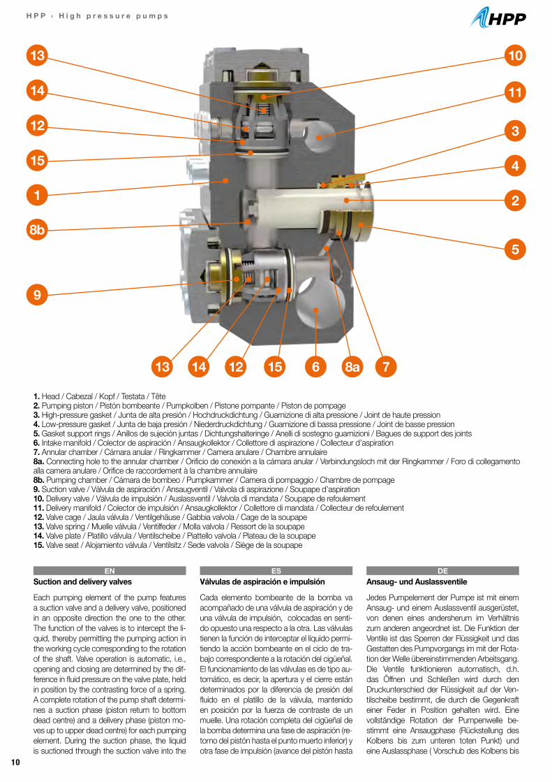
1. Head / Cabezal / Kopf / Testata / Tête2. Pumping piston / Pistón bombeante / Pumpkolben / Pistone pompante / Piston de pompage3. High-pressure gasket / Junta de alta presión / Hochdruckdichtung / Guarnizione di alta pressione / Joint de haute pression4. Low-pressure gasket / Junta de baja presión / Niederdruckdichtung / Guarnizione di bassa pressione / Joint de basse pression5. Gasket support rings / Anillos de sujeción juntas / Dichtungshalteringe / Anelli di sostegno guarnizioni / Bagues de support des joints6. Intake manifold / Colector de aspiración / Ansaugkollektor / Collettore di aspirazione / Collecteur d’aspiration7. Annular chamber / Cámara anular / Ringkammer / Camera anulare / Chambre annulaire8a. Connecting hole to the annular chamber / Orificio de conexión a la cámara anular / Verbindungsloch mit der Ringkammer / Foro di collegamento alla camera anulare / Orifice de raccordement à la chambre annulaire8b. Pumping chamber / Cámara de bombeo / Pumpkammer / Camera di pompaggio / Chambre de pompage9. Suction valve / Válvula de aspiración / Ansaugventil / Valvola di aspirazione / Soupape d’aspiration10. Delivery valve / Válvula de impulsión / Auslassventil / Valvola di mandata / Soupape de refoulement11. Delivery manifold / Colector de impulsión / Ansaugkollektor / Collettore di mandata / Collecteur de refoulement12. Valve cage / Jaula válvula / Ventilgehäuse / Gabbia valvola / Cage de la soupape13. Valve spring / Muelle válvula / Ventilfeder / Molla valvola / Ressort de la soupape14. Valve plate / Platillo válvula / Ventilscheibe / Piattello valvola / Plateau de la soupape15. Valve seat / Alojamiento válvula / Ventilsitz / Sede valvola / Siège de la soupape
13
13 14 12 15 6 8a 7
14
12
15
1
8b5
2
4
3
10
11
9
Suction and delivery valves
Each pumping element of the pump features a suction valve and a delivery valve, positioned in an opposite direction the one to the other. The function of the valves is to intercept the li-quid, thereby permitting the pumping action in the working cycle corresponding to the rotation of the shaft. Valve operation is automatic, i.e., opening and closing are determined by the dif-ference in fluid pressure on the valve plate, held in position by the contrasting force of a spring. A complete rotation of the pump shaft determi-nes a suction phase (piston return to bottom dead centre) and a delivery phase (piston mo-ves up to upper dead centre) for each pumping element. During the suction phase, the liquid is suctioned through the suction valve into the
Válvulas de aspiración e impulsión
Cada elemento bombeante de la bomba va acompañado de una válvula de aspiración y de una válvula de impulsión, colocadas en senti-do opuesto una respecto a la otra. Las válvulas tienen la función de interceptar el líquido permi-tiendo la acción bombeante en el ciclo de tra-bajo correspondiente a la rotación del cigüeñal. El funcionamiento de las válvulas es de tipo au-tomático, es decir, la apertura y el cierre están determinados por la diferencia de presión del fluido en el platillo de la válvula, mantenido en posición por la fuerza de contraste de un muelle. Una rotación completa del cigüeñal de la bomba determina una fase de aspiración (re-torno del pistón hasta el punto muerto inferior) y otra fase de impulsión (avance del pistón hasta
Ansaug- und Auslassventile
Jedes Pumpelement der Pumpe ist mit einem Ansaug- und einem Auslassventil ausgerüstet, von denen eines andersherum im Verhältnis zum anderen angeordnet ist. Die Funktion der Ventile ist das Sperren der Flüssigkeit und das Gestatten des Pumpvorgangs im mit der Rota-tion der Welle übereinstimmenden Arbeitsgang.Die Ventile funktionieren automatisch, d.h. das Öffnen und Schließen wird durch den Druckunterschied der Flüssigkeit auf der Ven-tilscheibe bestimmt, die durch die Gegenkraft einer Feder in Position gehalten wird. Eine vollständige Rotation der Pumpenwelle be-stimmt eine Ansaugphase (Rückstellung des Kolbens bis zum unteren toten Punkt) und eine Auslassphase ( Vorschub des Kolbens bis
EN ES DE
11
H P P › H i g h p r e s s u r e p u m p s
Efficiency
The efficiency of the Plunger pumps is determi-ned by the following physical quantities:- Flow rate- Pressure- Power
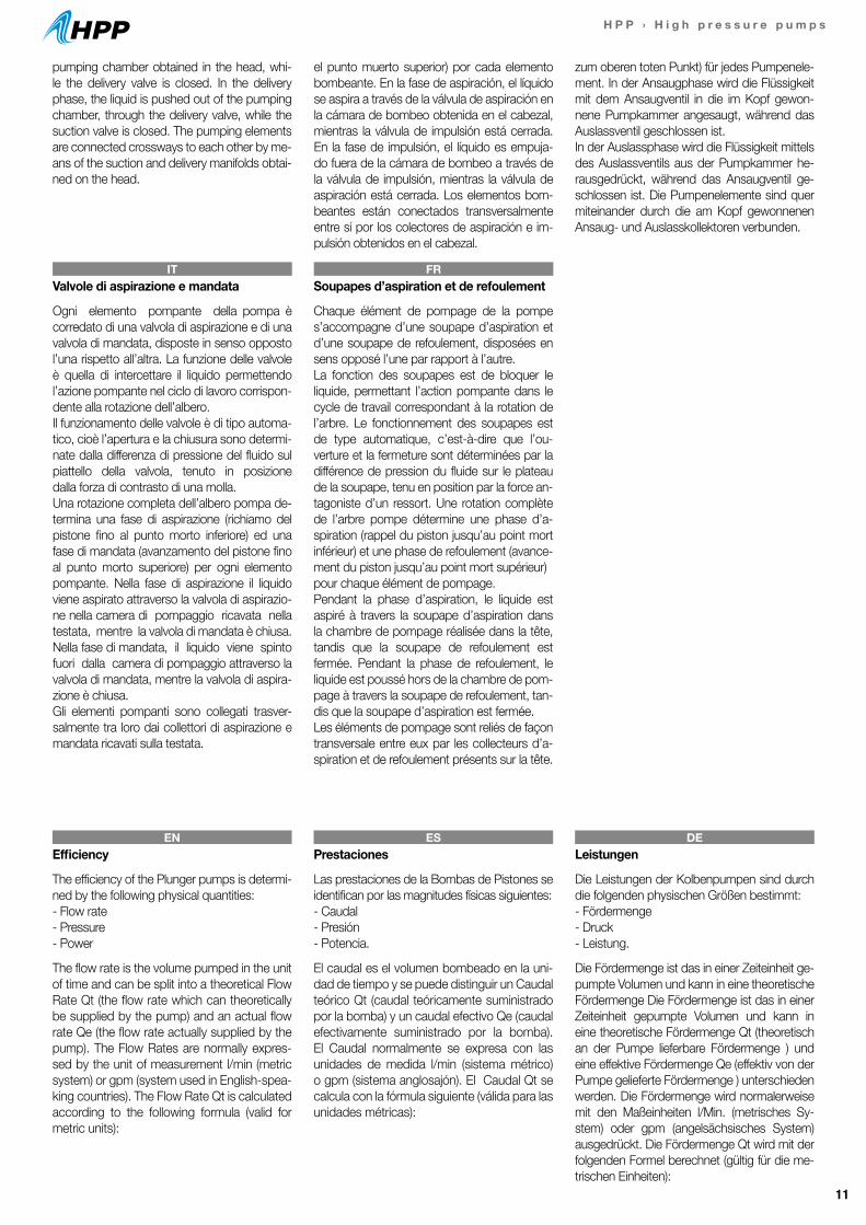
The flow rate is the volume pumped in the unit of time and can be split into a theoretical Flow Rate Qt (the flow rate which can theoretically be supplied by the pump) and an actual flow rate Qe (the flow rate actually supplied by the pump). The Flow Rates are normally expres-sed by the unit of measurement l/min (metric system) or gpm (system used in English-spea-king countries). The Flow Rate Qt is calculated according to the following formula (valid for metric units):
Prestaciones
Las prestaciones de la Bombas de Pistones se identifican por las magnitudes físicas siguientes:- Caudal- Presión- Potencia.
El caudal es el volumen bombeado en la uni-dad de tiempo y se puede distinguir un Caudal teórico Qt (caudal teóricamente suministrado por la bomba) y un caudal efectivo Qe (caudal efectivamente suministrado por la bomba). El Caudal normalmente se expresa con las unidades de medida l/min (sistema métrico) o gpm (sistema anglosajón). El Caudal Qt se calcula con la fórmula siguiente (válida para las unidades métricas):
Leistungen
Die Leistungen der Kolbenpumpen sind durch die folgenden physischen Größen bestimmt:- Fördermenge- Druck- Leistung.
Die Fördermenge ist das in einer Zeiteinheit ge-pumpte Volumen und kann in eine theoretische Fördermenge Die Fördermenge ist das in einer Zeiteinheit gepumpte Volumen und kann in eine theoretische Fördermenge Qt (theoretisch an der Pumpe lieferbare Fördermenge ) und eine effektive Fördermenge Qe (effektiv von der Pumpe gelieferte Fördermenge ) unterschieden werden. Die Fördermenge wird normalerweise mit den Maßeinheiten l/Min. (metrisches Sy-stem) oder gpm (angelsächsisches System) ausgedrückt. Die Fördermenge Qt wird mit der folgenden Formel berechnet (gültig für die me-trischen Einheiten):
EN ES DE
Valvole di aspirazione e mandata
Ogni elemento pompante della pompa è corredato di una valvola di aspirazione e di una valvola di mandata, disposte in senso opposto l’una rispetto all’altra. La funzione delle valvole è quella di intercettare il liquido permettendo l’azione pompante nel ciclo di lavoro corrispon-dente alla rotazione dell’albero.Il funzionamento delle valvole è di tipo automa-tico, cioè l’apertura e la chiusura sono determi-nate dalla differenza di pressione del fluido sul piattello della valvola, tenuto in posizione dalla forza di contrasto di una molla.Una rotazione completa dell’albero pompa de-termina una fase di aspirazione (richiamo del pistone fino al punto morto inferiore) ed una fase di mandata (avanzamento del pistone fino al punto morto superiore) per ogni elemento pompante. Nella fase di aspirazione il liquido viene aspirato attraverso la valvola di aspirazio-ne nella camera di pompaggio ricavata nella testata, mentre la valvola di mandata è chiusa. Nella fase di mandata, il liquido viene spinto fuori dalla camera di pompaggio attraverso la valvola di mandata, mentre la valvola di aspira-zione è chiusa.Gli elementi pompanti sono collegati trasver-salmente tra loro dai collettori di aspirazione e mandata ricavati sulla testata.
Soupapes d’aspiration et de refoulement
Chaque élément de pompage de la pompe s’accompagne d’une soupape d’aspiration et d’une soupape de refoulement, disposées en sens opposé l’une par rapport à l’autre.La fonction des soupapes est de bloquer le liquide, permettant l’action pompante dans le cycle de travail correspondant à la rotation de l’arbre. Le fonctionnement des soupapes est de type automatique, c’est-à-dire que l’ou-verture et la fermeture sont déterminées par la différence de pression du fluide sur le plateau de la soupape, tenu en position par la force an-tagoniste d’un ressort. Une rotation complète de l’arbre pompe détermine une phase d’a-spiration (rappel du piston jusqu’au point mort inférieur) et une phase de refoulement (avance-ment du piston jusqu’au point mort supérieur)pour chaque élément de pompage.Pendant la phase d’aspiration, le liquide est aspiré à travers la soupape d’aspiration dans la chambre de pompage réalisée dans la tête, tandis que la soupape de refoulement est fermée. Pendant la phase de refoulement, le liquide est poussé hors de la chambre de pom-page à travers la soupape de refoulement, tan-dis que la soupape d’aspiration est fermée.Les éléments de pompage sont reliés de façon transversale entre eux par les collecteurs d’a-spiration et de refoulement présents sur la tête.
IT FR
pumping chamber obtained in the head, whi-le the delivery valve is closed. In the delivery phase, the liquid is pushed out of the pumping chamber, through the delivery valve, while the suction valve is closed. The pumping elements are connected crossways to each other by me-ans of the suction and delivery manifolds obtai-ned on the head.
el punto muerto superior) por cada elemento bombeante. En la fase de aspiración, el líquido se aspira a través de la válvula de aspiración en la cámara de bombeo obtenida en el cabezal, mientras la válvula de impulsión está cerrada. En la fase de impulsión, el líquido es empuja-do fuera de la cámara de bombeo a través de la válvula de impulsión, mientras la válvula de aspiración está cerrada. Los elementos bom-beantes están conectados transversalmente entre sí por los colectores de aspiración e im-pulsión obtenidos en el cabezal.
zum oberen toten Punkt) für jedes Pumpenele-ment. In der Ansaugphase wird die Flüssigkeit mit dem Ansaugventil in die im Kopf gewon-nene Pumpkammer angesaugt, während das Auslassventil geschlossen ist. In der Auslassphase wird die Flüssigkeit mittels des Auslassventils aus der Pumpkammer he-rausgedrückt, während das Ansaugventil ge-schlossen ist. Die Pumpenelemente sind quer miteinander durch die am Kopf gewonnenen Ansaug- und Auslasskollektoren verbunden.
12
H P P › H i g h p r e s s u r e p u m p s
Prestazioni
Le prestazioni delle Pompe a Pistoni sono indi-viduate dalle seguenti grandezze fisiche:- Portata- Pressione- Potenza.
La portata è il volume pompato nell’unità di tempo e si può distinguere una Portata teorica Qt (portata teoricamente fornibile dalla pompa) e una portata effettiva Qe (portata effettivamen-te fornita dalla pompa). La Portata si esprime normalmente con le unità di misura l/min (siste-ma metrico) o gpm (sistema anglosassone). La Portata Qt si calcola con la seguente formula (valida per le unità metriche):
Performances
Les performances des pompes à pistons se di-stinguent par leurs caractéristiques physiques :- Débit- Pression- Puissance.
Le débit est le volume pompé dans l’unité de temps et on peut distinguer entre débit théori-que Qt (débit pouvant être théoriquement fourni par la pompe) et débit effectif Qe (débit effecti-vement fourni par la pompe). Le débit est nor-malement exprimé avec les unités de mesure l/min (système métrique) ou gpm (système anglo-saxon). Le débit Qt est calculé avec la formule suivante (valable pour les unités métriques) :
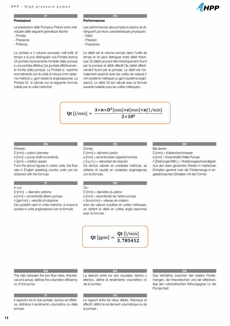
In cui:D [mm] = diametro pistonee [mm] = eccentricità albero pompan [giri/min] = velocità di rotazioneDai suddetti valori in unità metriche, si ricava la portata in unità anglosassoni con la formula:
Il rapporto tra le due portate, teorica ed effetti-va, definisce il rendimento volumetrico ηv della pompa:
Où :D [mm] = diamètre du pistone [mm] = excentricité de l’arbre pompen [tours/min] = vitesse de rotationavec les valeurs susdites en unités métriques, on obtient le débit en unités anglo-saxonnes avec la formule :
Le rapport entre les deux débits, théorique et effectif, définit le rendement volumétrique ηv de la pompe :
IT
IT
IT
FR
FR
FR
Wherein:D [mm] = piston diametere [mm] = pump shaft eccentricityn [rpm] = rotation speedFrom the above figures in metric units, the flow rate in English speaking country units can be obtained with the formula:
The ratio between the two flow rates, theoreti-cal and actual, defines the volumetric efficiency ηv of the pump:
Donde:D [mm] = diámetro pistóne [mm] = excentricidad cigüeñal bomban [r.p.m.] = velocidad de rotaciónDe dichos valores en unidades métricas, se obtiene el caudal en unidades anglosajonas con la fórmula:
La relación entre los dos caudales, teórico y efectivo, define el rendimiento volumétrico ηv de la bomba:
Bei denen:D [mm] = Kolbendurchmessere [mm] = Exzentrizität Welle Pumpen [Drehungen/Min.] = RotationsgeschwindigkeitAus den oben genannten Werten in metrischen Einheiten gewinnt man die Fördermenge in an-gelsächsischen Einheiten mit der Formel:
Das Verhältnis zwischen den beiden Förder-mengen, der theoretischen und der effektiven, legt den volumetrischen Wirkungsgrad ηv der Pumpe fest:
EN
EN
ES
ES
DE
DE
5
Il funzionamento delle valvole è di tipo automatico, cioè l’apertura e la chiusura sono determinate dalla differenza di pressione del fluido sul piattello della valvola, tenuto in posizione dalla forza di contrasto di una molla. Una rotazione completa dell’albero pompa determina una fase di aspirazione (richiamo del pistone fino al punto morto inferiore) ed una fase di mandata (avanzamento del pistone fino al punto morto superiore) per ogni elemento pompante. Nella fase di aspirazione il liquido viene aspirato attraverso la valvola di aspirazione nella camera di pompaggio ricavata nella testata, mentre la valvola di mandata è chiusa. Nella fase di mandata, il liquido viene spinto fuori dalla camera di pompaggio attraverso la valvola di mandata, mentre la valvola di aspirazione è chiusa. Gli elementi pompanti sono collegati trasversalmente tra loro dai collettori di aspirazione e mandata ricavati sulla testata.
POMPE A PISTONI COMET - IL CALCOLO DELLE PRESTAZIONI Le prestazioni delle Pompe a Pistoni sono individuate dalle seguenti grandezze fisiche:
- Portata - Pressione - Potenza.
La portata è il volume pompato nell’unità di tempo e si può distinguere una Portata teorica Qt (portata teoricamente fornibile dalla pompa) e una portata effettiva Qe (portata effettivamente fornita dalla pompa). La Portata si esprime normalmente con le unità di misura l/min (sistema metrico) o gpm (sistema anglosassone). La Portata Qt per le pompe a tre pistoni in linea si calcola con la seguente formula (valida per le unità metriche):
𝐐𝐐𝐐𝐐 [l/min] = 𝟑𝟑×𝛑𝛑×𝐃𝐃𝟐𝟐 mm ×𝐞𝐞 mm ×𝐧𝐧[1/min]
𝟐𝟐×𝟏𝟏𝟏𝟏𝟔𝟔 In cui D[mm] = diametro pistone e [mm] = eccentricità albero pompa n [giri/min] = velocità di rotazione La Portata Qt per le pompe a tre pistoni assiali si calcola invece con la seguente formula (valida per le unità metriche):
𝐐𝐐𝐐𝐐 [l/min] = 𝟑𝟑×𝛑𝛑×𝐃𝐃𝟐𝟐 mm ×𝐢𝐢 mm × 𝐭𝐭𝐭𝐭𝐭𝐭𝛂𝛂×𝐧𝐧[1/min]
𝟐𝟐×𝟏𝟏𝟏𝟏𝟔𝟔 In cui D[mm] = diametro pistone i [mm] = interasse pistoni (distanza tra asse della pompa e asse di un pistone) 𝛂𝛂 [rad] = angolo inclinazione piattello pompa n [giri/min] = velocità di rotazione
6
Dai suddetti valori in unità metriche, si ricava la portata in unità anglosassoni con la formula:
𝐐𝐐𝐐𝐐 gpm = 𝐐𝐐𝐐𝐐 [l/min]𝟑𝟑,𝟕𝟕𝟕𝟕𝟕𝟕𝟕𝟕𝟕𝟕𝟕𝟕
Il rapporto tra le due portate, teorica ed effettiva, definisce il rendimento volumetrico ηv della pompa:
η v = 𝐐𝐐𝐞𝐞
𝐐𝐐𝐭𝐭
I valori di portata che compaiono nelle prestazioni a catalogo sono quelli della portata effettiva Qe. La portata delle pompe volumetriche a pistoni è proporzionale alla velocità di rotazione ed è tendenzialmente indipendente dalla pressione di mandata, tendendo però a diminuire all’aumentare di quest’ultima.
La pressione è il valore massimo che si può avere nella testata della pompa in condizioni di lavoro. Qui occorre precisare che le pompe volumetriche a pistoni non sviluppano intrinsecamente pressione nel loro movimento, ma spostano liquido in virtù delle loro caratteristiche costruttive come descritto nel capitolo precedente. Se però a valle della pompa, nel circuito di mandata, è presente un’ostruzione (ad esempio un ugello), si genera nella testata della pompa la pressione che è necessaria affinchè la portata della pompa possa attraversare l’ostruzione incontrata. E’ pertanto necessario che nel circuito di mandata sia presente una valvola di massima pressione che non permetta l’instaurarsi di una pressione superiore a quella massima, stabilita in base alle caratteristiche di resistenza della pompa. Infatti se l’ostruzione di cui sopra dovesse essere completa (ad esempio la chiusura totale del circuito di mandata), la pressione tenderebbe ad un valore infinitamente grande con la conseguente rottura della testata. L’inserimento di una valvola di by-pass regolabile permette inoltre di stabilire un determinato valore di pressione in base alle esigenze di utilizzo. La Pressione si esprime, in unità metriche, in bar, in MPa, e in unità anglosassoni in PSI. Le relazioni tra le suddette unità di misura sono le seguenti:
𝐏𝐏 MPa = 𝐏𝐏 bar ×𝟎𝟎,𝟏𝟏
𝐏𝐏 PSI = 𝐏𝐏 bar ×𝟏𝟏𝟏𝟏,𝟓𝟓𝟓𝟓𝟓𝟓𝟓𝟓𝟓𝟓 La potenza utile Nu di una pompa è l’energia fornita al liquido pompato nell’unità di tempo, mentre la potenza assorbita Na è l’energia nell’unità di tempo che la pompa richiede alla sua fonte di energia (motore elettrico, termico, oleodinamico, etc.) per effettuare il lavoro di pompaggio richiesto. Le unità di misura utilizzate per esprimere la Potenza sono kW, CV e HP. La potenza utile Nu si calcole con la formula:
𝐍𝐍𝐮𝐮 [kW] = 𝐐𝐐𝐐𝐐 l/min ×𝐏𝐏 bar
𝟔𝟔𝟔𝟔𝟔𝟔 Le relazioni tra le altre unità di misura della potenza sono le seguenti:

13
H P P › H i g h p r e s s u r e p u m p s
The flow rate figures shown in the catalogue ef-ficiency are those of the theoretical flow rate Qt, i.e., with volumetric efficiency ηv = 1.The flow rate of positive-displacement plunger pumps is proportionate to the rotation speed and tends to be independent from the delivery pressure, while tending however to decrease with the increase of the latter. The pressure is the maximum value which can exist in the pump head in operating conditions. It must be poin-ted out here that positive-displacement plunger pumps do not intrinsically develop pressure during their movement, but move the liquid by virtue of their construction characteristics as described in the previous chapter. If however, downstream of the pump, in the delivery circuit, there is an obstacle (e.g., a nozzle), the pressu-re needed to enable the pump flow to cross the encountered obstacle is generated in the pump head. The delivery circuit must therefore feature a maximum pressure valve which prevents the occurrence of a pressure above the maximum pressure, set on the basis of the pump resi-stance characteristics. In fact, if the above ob-stacle were to form a complete blockage (e.g., total closing of the delivery circuit), the pressure would increase exponentially with consequent breakage of the head. If an adjustable by-pass valve is fitted, furthermore, a determinate pres-sure value can be set according to operating needs. Pressure is indicated in metric units, in bar, in MPa and in English-speaking country units in PSI. The relations between the above units of measurement are the following:
Los valores de caudal que aparecen en las prestaciones del catálogo son los del caudal teórico Qt, o sea, con rendimiento volumétrico ηv=1. El caudal de las bombas volumétricas de pistones es proporcional a la velocidad de ro-tación y tendencialmente es independiente de la presión de impulsión, tendiendo a disminuir conforme aumenta ésta última. La presión es el valor máximo que se puede obtener en el cabezal de la bomba en condiciones de traba-jo. Aquí es necesario precisar que las bombas volumétricas de pistones no desarrollan intrín-secamente presión en su movimiento, pero desplazan líquido en virtud de sus característi-cas constructivas, tal como se describe en el capítulo anterior. Pero si detrás de la bomba, en el circuito de impulsión, hay una obstrucción (por ejemplo, una boquilla), en el cabezal de la bomba se genera la presión necesaria, de manera que la bomba pueda atravesar la ob-strucción encontrada. Por lo tanto, es necesa-rio que en el circuito de impulsión se encuentre una válvula de máxima presión que no permita que se instaure una presión superior a la máxi-ma, establecida en base a las características de resistencia de la bomba. Efectivamente, si la obstrucción citada arriba fuera total, (por ejemplo, el cierre total del circuito de impul-sión), la presión se aproximaría a un valor in-finitamente grande con la consiguiente rotura del cabezal. La introducción de una válvula de by-pass regulable permite además establecer un determinado valor de presión en función de las exigencias de uso. La Presión se expresa en unidades métricas, en bar, en MPa y en unida-des del sistema anglosajón en PSI.Las relaciones entre dichas unidades de medi-da son las siguientes:
Die Fördermengenwerte, die bei den Leistungen im Katalog erscheinen, sind diejenigen der the-oretischen Fördermenge Qt, d.h. mit volumetri-schem Wirkungsgrad ηv = 1.Die Fördermenge der volumetrischen Kol-benpumpen ist proportional zur Rotationsge-schwindigkeit und tendentiell unabhängig vom Auslassdruck, wobei sie aber dazu tendiert, bei Zunahme des letzteren abzunehmen. Der Druck ist der Höchstwert, den man am Pumpenkopf unter Betriebsbedingungen erreichen kann. Hier ist zu präzisieren, dass die volumetrischen Kolbenpumpen nicht intrinsisch Druck bei ihrer Bewegung entwickeln, sondern Flüssigkeit, wie im vorausgehenden Kapitel beschrieben, durch ihre baulichen Eigenschaften verschieben. Wenn im Auslasskreislauf jedoch unterhalb der Pum-pe ein Hindernis (z.B. eine Düse) vorhanden ist, wird im Kopf der Pumpe der Druck erzeugt, der nötig ist, damit die Fördermenge der Pumpe das vorgefundene Hindernis passieren kann. Es ist daher nötig, dass im Auslasskreislauf ein Über-druckventil vorhanden ist, das es nicht gestat-tet, dass ein Druck über dem Höchstdruck dort herrscht, der auf Grundlage der Widerstandsei-genschaften der Pumpe festgelegt wird. Sollte die oben angegebene Verstopfung vollständig sein (zum Beispiel das völlige Schließen des Auslasskreislaufs), würde der Druck nämlich zu einem unendlich hohen Wert mit daraus folgen-dem Defekt des Kopfes tendieren. Das Einfügen eines regulierbaren Bypass-Ventils gestattet außerdem die Festlegung eines bestimmten Druckwerts auf Grundlage der Verwendungser-fordernisse. Der Druck wird in metrischen Einhei-ten, in bar, in Mpa und in angelsächsischen Einheiten in PSI ausgedrückt. Die Verhältnisse zwischen den oben genannten Maßeinheiten sind die folgenden:
EN ES DE
I valori di portata che compaiono nelle presta-zioni a catalogo sono quelli della portata teorica Qt, cioè con rendimento volumetrico ηv = 1. La portata delle pompe volumetriche a pistoni è proporzionale alla velocità di rotazione ed è tendenzialmente indipendente dalla pressione di mandata, tendendo però a diminuire all’au-mentare di quest’ultima. La pressione è il valore massimo che si può avere nella testata della pompa in condizioni di lavoro. Qui occorre precisare che le pompe volumetriche a pistoni non sviluppano in-trinsecamente pressione nel loro movimento, ma spostano liquido in virtù delle loro caratteri-stiche costruttive come descritto nel capitolo precedente. Se però a valle della pompa, nel circuito di mandata, è presente un’ostruzione
Les valeurs de débit indiquées dans les perfor-mances de ce catalogue sont celles du débit théorique Qt, c’est-à-dire avec un rendement volumétrique ηv=1. Le débit des pompes vo-lumétriques à pistons est proportionnel à la vi-tesse de rotation et est généralement indépen-dant de la pression de refoulement, ayant cependant tendance à diminuer lorsque celle-ci augmente. La pression est la valeur maximum que l’on peut avoir dans la tête de la pompe en conditions de travail. Il faut ici préciser que les pompes volumétriques à pistons ne dévelop-pent pas de façon intrinsèque de la pression dans leur mouvement, mais déplacent le liqui-de en vertu de leurs caractéristiques de con-struction, tel que cela est décrit dans le chapitre précédent. Si, cependant, en aval de la pompe,
IT FR
6
Dai suddetti valori in unità metriche, si ricava la portata in unità anglosassoni con la formula:
𝐐𝐐𝐐𝐐 gpm = 𝐐𝐐𝐐𝐐 [l/min]𝟑𝟑,𝟕𝟕𝟕𝟕𝟕𝟕𝟕𝟕𝟕𝟕𝟕𝟕
Il rapporto tra le due portate, teorica ed effettiva, definisce il rendimento volumetrico ηv della pompa:
η v = 𝐐𝐐𝐞𝐞
𝐐𝐐𝐭𝐭
I valori di portata che compaiono nelle prestazioni a catalogo sono quelli della portata effettiva Qe. La portata delle pompe volumetriche a pistoni è proporzionale alla velocità di rotazione ed è tendenzialmente indipendente dalla pressione di mandata, tendendo però a diminuire all’aumentare di quest’ultima.
La pressione è il valore massimo che si può avere nella testata della pompa in condizioni di lavoro. Qui occorre precisare che le pompe volumetriche a pistoni non sviluppano intrinsecamente pressione nel loro movimento, ma spostano liquido in virtù delle loro caratteristiche costruttive come descritto nel capitolo precedente. Se però a valle della pompa, nel circuito di mandata, è presente un’ostruzione (ad esempio un ugello), si genera nella testata della pompa la pressione che è necessaria affinchè la portata della pompa possa attraversare l’ostruzione incontrata. E’ pertanto necessario che nel circuito di mandata sia presente una valvola di massima pressione che non permetta l’instaurarsi di una pressione superiore a quella massima, stabilita in base alle caratteristiche di resistenza della pompa. Infatti se l’ostruzione di cui sopra dovesse essere completa (ad esempio la chiusura totale del circuito di mandata), la pressione tenderebbe ad un valore infinitamente grande con la conseguente rottura della testata. L’inserimento di una valvola di by-pass regolabile permette inoltre di stabilire un determinato valore di pressione in base alle esigenze di utilizzo. La Pressione si esprime, in unità metriche, in bar, in MPa, e in unità anglosassoni in PSI. Le relazioni tra le suddette unità di misura sono le seguenti:
𝐏𝐏 MPa = 𝐏𝐏 bar ×𝟎𝟎,𝟏𝟏
𝐏𝐏 PSI = 𝐏𝐏 bar ×𝟏𝟏𝟏𝟏,𝟓𝟓𝟓𝟓𝟓𝟓𝟓𝟓𝟓𝟓 La potenza utile Nu di una pompa è l’energia fornita al liquido pompato nell’unità di tempo, mentre la potenza assorbita Na è l’energia nell’unità di tempo che la pompa richiede alla sua fonte di energia (motore elettrico, termico, oleodinamico, etc.) per effettuare il lavoro di pompaggio richiesto. Le unità di misura utilizzate per esprimere la Potenza sono kW, CV e HP. La potenza utile Nu si calcole con la formula:
𝐍𝐍𝐮𝐮 [kW] = 𝐐𝐐𝐐𝐐 l/min ×𝐏𝐏 bar
𝟔𝟔𝟔𝟔𝟔𝟔 Le relazioni tra le altre unità di misura della potenza sono le seguenti:
14
H P P › H i g h p r e s s u r e p u m p s
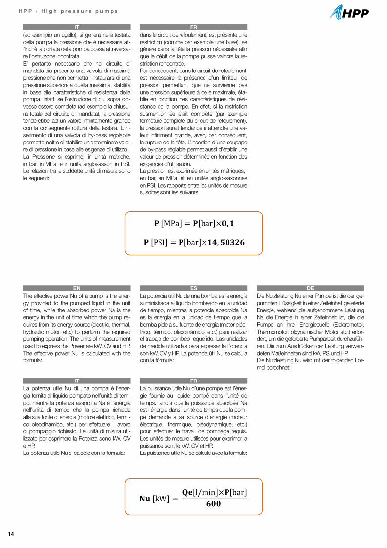
(ad esempio un ugello), si genera nella testata della pompa la pressione che è necessaria af-finchè la portata della pompa possa attraversa-re l’ostruzione incontrata. E’ pertanto necessario che nel circuito di mandata sia presente una valvola di massima pressione che non permetta l’instaurarsi di una pressione superiore a quella massima, stabilita in base alle caratteristiche di resistenza della pompa. Infatti se l’ostruzione di cui sopra do-vesse essere completa (ad esempio la chiusu-ra totale del circuito di mandata), la pressione tenderebbe ad un valore infinitamente grande con la conseguente rottura della testata. L’in-serimento di una valvola di by-pass regolabile permette inoltre di stabilire un determinato valo-re di pressione in base alle esigenze di utilizzo.La Pressione si esprime, in unità metriche, in bar, in MPa, e in unità anglosassoni in PSI. Le relazioni tra le suddette unità di misura sono le seguenti:
dans le circuit de refoulement, est présente une restriction (comme par exemple une buse), se génère dans la tête la pression nécessaire afin que le débit de la pompe puisse vaincre la re-striction rencontrée.Par conséquent, dans le circuit de refoulementest nécessaire la présence d’un limiteur de pression permettant que ne survienne pas une pression supérieure à celle maximale, éta-blie en fonction des caractéristiques de rési-stance de la pompe. En effet, si la restriction susmentionnée était complète (par exemple fermeture complète du circuit de refoulement), la pression aurait tendance à atteindre une va-leur infiniment grande, avec, par conséquent, la rupture de la tête. L’insertion d’une soupape de by-pass réglable permet aussi d’établir une valeur de pression déterminée en fonction des exigences d’utilisation.La pression est exprimée en unités métriques,en bar, en MPa, et en unités anglo-saxonnes en PSI. Les rapports entre les unités de mesure susdites sont les suivants:
IT FR
La potenza utile Nu di una pompa è l’ener-gia fornita al liquido pompato nell’unità di tem-po, mentre la potenza assorbita Na è l’energia nell’unità di tempo che la pompa richiede alla sua fonte di energia (motore elettrico, termi-co, oleodinamico, etc.) per effettuare il lavoro di pompaggio richiesto. Le unità di misura uti-lizzate per esprimere la Potenza sono kW, CV e HP.La potenza utile Nu si calcole con la formula:
La puissance utile Nu d’une pompe est l’éner-gie fournie au liquide pompé dans l’unité de temps, tandis que la puissance absorbée Na est l’énergie dans l’unité de temps que la pom-pe demande à sa source d’énergie (moteur électrique, thermique, oléodynamique, etc.) pour effectuer le travail de pompage requis. Les unités de mesure utilisées pour exprimer la puissance sont le kW, CV et HP.La puissance utile Nu se calcule avec la formule:
IT FR
The effective power Nu of a pump is the ener-gy provided to the pumped liquid in the unit of time, while the absorbed power Na is the energy in the unit of time which the pump re-quires from its energy source (electric, thermal, hydraulic motor, etc.) to perform the required pumping operation. The units of measurement used to express the Power are kW, CV and HP.The effective power Nu is calculated with the formula:
La potencia útil Nu de una bomba es la energía suministrada al líquido bombeado en la unidad de tiempo, mientras la potencia absorbida Na es la energía en la unidad de tiempo que la bomba pide a su fuente de energía (motor eléc-trico, térmico, oleodinámico, etc.) para realizar el trabajo de bombeo requerido. Las unidades de medida utilizadas para expresar la Potencia son kW, CV y HP. La potencia útil Nu se calcula con la fórmula:
Die Nutzleistung Nu einer Pumpe ist die der ge-pumpten Flüssigkeit in einer Zeiteinheit gelieferte Energie, während die aufgenommene Leistung Na die Energie in einer Zeiteinheit ist, die die Pumpe an ihrer Energiequelle (Elektromotor, Thermomotor, öldynamischer Motor etc.) erfor-dert, um die geforderte Pumparbeit durchzufüh-ren. Die zum Ausdrücken der Leistung verwen-deten Maßeinheiten sind kW, PS und HP.Die Nutzleistung Nu wird mit der folgenden For-mel berechnet:
EN ES DE
6
Dai suddetti valori in unità metriche, si ricava la portata in unità anglosassoni con la formula:
𝐐𝐐𝐐𝐐 gpm = 𝐐𝐐𝐐𝐐 [l/min]𝟑𝟑,𝟕𝟕𝟕𝟕𝟕𝟕𝟕𝟕𝟕𝟕𝟕𝟕
Il rapporto tra le due portate, teorica ed effettiva, definisce il rendimento volumetrico ηv della pompa:
η v = 𝐐𝐐𝐞𝐞
𝐐𝐐𝐭𝐭
I valori di portata che compaiono nelle prestazioni a catalogo sono quelli della portata effettiva Qe. La portata delle pompe volumetriche a pistoni è proporzionale alla velocità di rotazione ed è tendenzialmente indipendente dalla pressione di mandata, tendendo però a diminuire all’aumentare di quest’ultima.
La pressione è il valore massimo che si può avere nella testata della pompa in condizioni di lavoro. Qui occorre precisare che le pompe volumetriche a pistoni non sviluppano intrinsecamente pressione nel loro movimento, ma spostano liquido in virtù delle loro caratteristiche costruttive come descritto nel capitolo precedente. Se però a valle della pompa, nel circuito di mandata, è presente un’ostruzione (ad esempio un ugello), si genera nella testata della pompa la pressione che è necessaria affinchè la portata della pompa possa attraversare l’ostruzione incontrata. E’ pertanto necessario che nel circuito di mandata sia presente una valvola di massima pressione che non permetta l’instaurarsi di una pressione superiore a quella massima, stabilita in base alle caratteristiche di resistenza della pompa. Infatti se l’ostruzione di cui sopra dovesse essere completa (ad esempio la chiusura totale del circuito di mandata), la pressione tenderebbe ad un valore infinitamente grande con la conseguente rottura della testata. L’inserimento di una valvola di by-pass regolabile permette inoltre di stabilire un determinato valore di pressione in base alle esigenze di utilizzo. La Pressione si esprime, in unità metriche, in bar, in MPa, e in unità anglosassoni in PSI. Le relazioni tra le suddette unità di misura sono le seguenti:
𝐏𝐏 MPa = 𝐏𝐏 bar ×𝟎𝟎,𝟏𝟏
𝐏𝐏 PSI = 𝐏𝐏 bar ×𝟏𝟏𝟏𝟏,𝟓𝟓𝟓𝟓𝟓𝟓𝟓𝟓𝟓𝟓 La potenza utile Nu di una pompa è l’energia fornita al liquido pompato nell’unità di tempo, mentre la potenza assorbita Na è l’energia nell’unità di tempo che la pompa richiede alla sua fonte di energia (motore elettrico, termico, oleodinamico, etc.) per effettuare il lavoro di pompaggio richiesto. Le unità di misura utilizzate per esprimere la Potenza sono kW, CV e HP. La potenza utile Nu si calcole con la formula:
𝐍𝐍𝐮𝐮 [kW] = 𝐐𝐐𝐐𝐐 l/min ×𝐏𝐏 bar
𝟔𝟔𝟔𝟔𝟔𝟔 Le relazioni tra le altre unità di misura della potenza sono le seguenti:
15
H P P › H i g h p r e s s u r e p u m p s
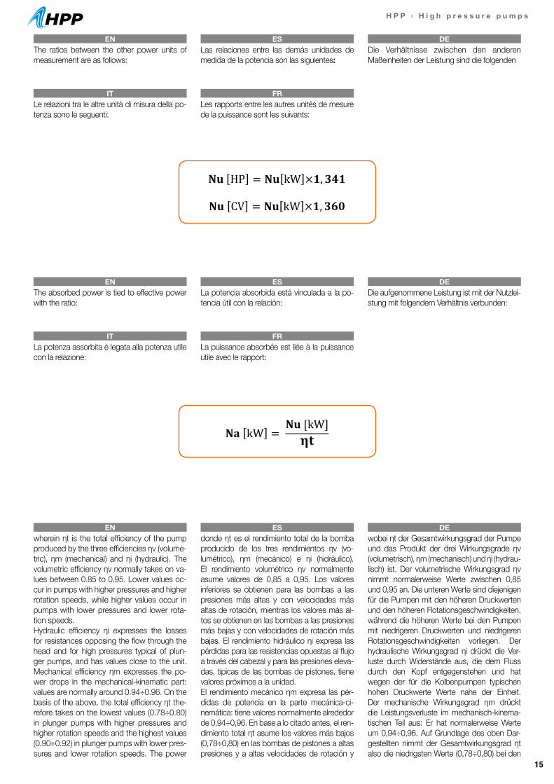
Le relazioni tra le altre unità di misura della po-tenza sono le seguenti:
La potenza assorbita è legata alla potenza utile con la relazione:
Les rapports entre les autres unités de mesure de la puissance sont les suivants:
La puissance absorbée est liée à la puissance utile avec le rapport:
IT
IT
FR
FR
The ratios between the other power units of measurement are as follows:
wherein ηt is the total efficiency of the pump produced by the three efficiencies ηv (volume-tric), ηm (mechanical) and ηi (hydraulic). The volumetric efficiency ηv normally takes on va-lues between 0.85 to 0.95. Lower values oc-cur in pumps with higher pressures and higher rotation speeds, while higher values occur in pumps with lower pressures and lower rota-tion speeds.Hydraulic efficiency ηi expresses the losses for resistances opposing the flow through the head and for high pressures typical of plun-ger pumps, and has values close to the unit. Mechanical efficiency ηm expresses the po-wer drops in the mechanical-kinematic part: values are normally around 0.94÷0.96. On the basis of the above, the total efficiency ηt the-refore takes on the lowest values (0.78÷0.80) in plunger pumps with higher pressures and higher rotation speeds and the highest values (0.90÷0.92) in plunger pumps with lower pres-sures and lower rotation speeds. The power
The absorbed power is tied to effective power with the ratio:
Las relaciones entre las demás unidades de medida de la potencia son las siguientes:
donde ηt es el rendimiento total de la bomba producido de los tres rendimientos ηv (vo-lumétrico), ηm (mecánico) e ηi (hidráulico). El rendimiento volumétrico ηv normalmente asume valores de 0,85 a 0,95. Los valores inferiores se obtienen para las bombas a las presiones más altas y con velocidades más altas de rotación, mientras los valores más al-tos se obtienen en las bombas a las presiones más bajas y con velocidades de rotación más bajas. El rendimiento hidráulico ηi expresa las pérdidas para las resistencias opuestas al flujo a través del cabezal y para las presiones eleva-das, típicas de las bombas de pistones, tiene valores próximos a la unidad.El rendimiento mecánico ηm expresa las pér-didas de potencia en la parte mecánica-ci-nemática: tiene valores normalmente alrededor de 0,94÷0,96. En base a lo citado antes, el ren-dimiento total ηt asume los valores más bajos (0,78÷0,80) en las bombas de pistones a altas presiones y a altas velocidades de rotación y
La potencia absorbida está vinculada a la po-tencia útil con la relación:
Die Verhältnisse zwischen den anderen Maßeinheiten der Leistung sind die folgenden
wobei ηt der Gesamtwirkungsgrad der Pumpe und das Produkt der drei Wirkungsgrade ηv (volumetrisch), ηm (mechanisch) und ηi (hydrau-lisch) ist. Der volumetrische Wirkungsgrad ηv nimmt normalerweise Werte zwischen 0,85 und 0,95 an. Die unteren Werte sind diejenigen für die Pumpen mit den höheren Druckwerten und den höheren Rotationsgeschwindigkeiten, während die höheren Werte bei den Pumpen mit niedrigeren Druckwerten und niedrigeren Rotationsgeschwindigkeiten vorliegen. Der hydraulische Wirkungsgrad ηi drückt die Ver-luste durch Widerstände aus, die dem Fluss durch den Kopf entgegenstehen und hat wegen der für die Kolbenpumpen typischen hohen Druckwerte Werte nahe der Einheit. Der mechanische Wirkungsgrad ηm drückt die Leistungsverluste im mechanisch-kinema-tischen Teil aus: Er hat normalerweise Werte um 0,94÷0,96. Auf Grundlage des oben Dar-gestellten nimmt der Gesamtwirkungsgrad ηt also die niedrigsten Werte (0,78÷0,80) bei den
Die aufgenommene Leistung ist mit der Nutzlei-stung mit folgendem Verhältnis verbunden:
EN
EN
EN
ES
ES
ES
DE
DE
DE
7
𝐍𝐍𝐍𝐍 HP = 𝐍𝐍𝐍𝐍 kW ×𝟏𝟏,𝟑𝟑𝟑𝟑𝟑𝟑
𝐍𝐍𝐍𝐍 CV = 𝐍𝐍𝐍𝐍 kW ×𝟏𝟏,𝟑𝟑𝟑𝟑𝟑𝟑
La potenza assorbita è legata alla potenza utile con la relazione:
𝐍𝐍𝐍𝐍 kW = 𝐍𝐍𝐍𝐍 [kW]𝛈𝛈𝐭𝐭
in cui 𝛈𝛈t è il rendimento totale della pompa prodotto dei tre rendimenti 𝛈𝛈v (volumetrico), 𝛈𝛈m (meccanico) e 𝛈𝛈i (idraulico). Il rendimento volumetrico 𝛈𝛈v assume normalmente valori da 0,85 a 0,95. I valori inferiori si hanno per le pompe a pistoni assiali e con l’aumento della velocità di rotazione, mentre i valori più alti si hanno nelle pompe a pistoni in linea e con basse velocità di rotazione. Il rendimento idraulico 𝛈𝛈i esprime le perdite per le resistenze opposte al flusso attraverso la testata e per le pressioni elevate, tipiche delle pompe a pistoni, ha valori prossimi all’unità. Il rendimento meccanico 𝛈𝛈m esprime le perdite di potenza nella parte meccanica-cinematica: ha valori superiori nelle pompe a pistoni in linea (0,94÷0,96) e valori inferiori nelle pompe a pistoni assiali (0,90÷0,92). In base a quanto sopra, il rendimento totale 𝛈𝛈t assume quindi i valori più bassi (0,78÷0,80) nelle pompe a pistoni assiali ad alta velocità di rotazione (3400 giri/min) e i valori più alti (0,90÷0,92) nelle pompe a pistoni in linea a bassa velocità di rotazione (1000÷1400 giri/min).
I valori di potenza che compaiono nelle prestazioni a catalogo sono quelli della potenza assorbita Nu. La potenza assorbita nelle pompe volumetriche a pistoni, con velocità di rotazione costante (e quindi a portata costante) è proporzionale alla pressione.
16
H P P › H i g h p r e s s u r e p u m p s
values shown in the catalogue efficiencies are those of the absorbed power Na. The absor-bed power in positive-displacement plunger pumps, with constant rotation speed (and the-refore with constant flow rate) is proportionate to pressure.
Kolbenpumpen mit den höchsten Druckwerten und der höchsten Rotationsgeschwindigkei-ten an und die höchsten Werte (0,90÷0,92) bei den Kolbenpumpen mit den niedrigsten Druckwerten und der niedrigsten Rotationsge-schwindigkeiten. Die Leistungswerte, die bei den Leistungen im Katalog erscheinen, sind die der aufgenommenen Leistung Na. Die aufge-nommene Leistung ist bei den volumetrischen Kolbenpumpen mit konstanter Rotationsge-schwindigkeit (und folglich konstanter Förder-menge) proportional zum Druck.
in cui ηt è il rendimento totale della pompa pro-dotto dei tre rendimenti ηv (volumetrico), ηm(meccanico) e ηi (idraulico). Il rendimento volumetrico ηv assume normal-mente valori da 0,85 a 0,95. I valori inferiori si hanno per le pompe a più alte pressioni e a più alte velocità di rotazione, mentre i valori più alti si hanno nelle pompe a pressioni più basse e a più basse velocità di rotazione. Il rendimento idraulico ηi esprime le perdite per le resistenze opposte al flusso attraverso la testata e per le pressioni elevate, tipiche delle pompe a pistoni, ha valori prossimi all’unità.Il rendimento meccanico ηm esprime le perdite di potenza nella parte meccanica-cinematica: ha valori normalmente intorno a 0,94÷0,96.In base a quanto sopra, il rendimento totale ηt assume quindi i valori più bassi (0,78÷0,80) nelle pompe a pistoni a più alte pressioni e a più alte velocità di rotazione e i valori più alti (0,90÷0,92) nelle pompe a pistoni a pressioni più basse e a più basse velocità di rotazione.I valori di potenza che compaiono nelle presta-zioni a catalogo sono quelli della potenza assorbita Na. La potenza assorbita nelle pom-pe volumetriche a pistoni, con velocità di rota-zione costante (e quindi a portata costante) è proporzionale alla pressione.
où ηt est le rendement total de la pompe produ-it par les trois rendements ηv (volumétrique), ηm (mécanique) et ηi (hydraulique). Le rendement volumétrique ηv présente normalement des valeurs allant de 0,85 à 0,95. On a des valeursinférieures pour les pompes à des pressions plus hautes et à des vitesses de rotation plus hautes, tandis que l’on a des valeurs supérieu-res dans les pompes à des pressions plus bas-ses et des vitesses de rotation plus basses.Le rendement hydraulique ηi exprime les pertes pour les résistances opposées au flux à travers la tête et pour les pressions élevées,typiques des pompes à pistons, on a des va-leurs proches de l’unité. Le rendement mécani-que ηm exprime les pertes de puissance dansla partie mécanique-cinématique: sa valeur s’élève normalement à 0,94÷0,96.Sur la base de ceci, le rendement total ηt présente des valeurs inférieures (0,78÷0,80) dans les pompes à pistons aux pressions plus élevées et aux vitesses de rotation plus élevées et des valeurs supérieures (0,90÷0,92) dans les pompes à pistons aux pressions plus basses et aux vitesses de rotation plus basses.Les valeurs de puissance qui sont indiquées pour les performances du catalogue sont cel-les de la puissance absorbée Na. La puissance absorbée dans les pompes volumétriques à pistons, avec vitesse de rotation constante (et donc à débit constant) est proportionnelle à la pression.
IT FR
los valores más altos (0,90÷0,92) en las bom-bas de pistones a bajas presiones y a bajas ve-locidades de rotación. Los valores de potencia que aparecen en las prestaciones del catálogo son los de la potencia absorbida Na. La poten-cia absorbida en las bombas volumétricas de pistones, con velocidad de rotación constante (y por tanto con caudal constante) es propor-cional a la presión.
17
H P P › H i g h p r e s s u r e p u m p s
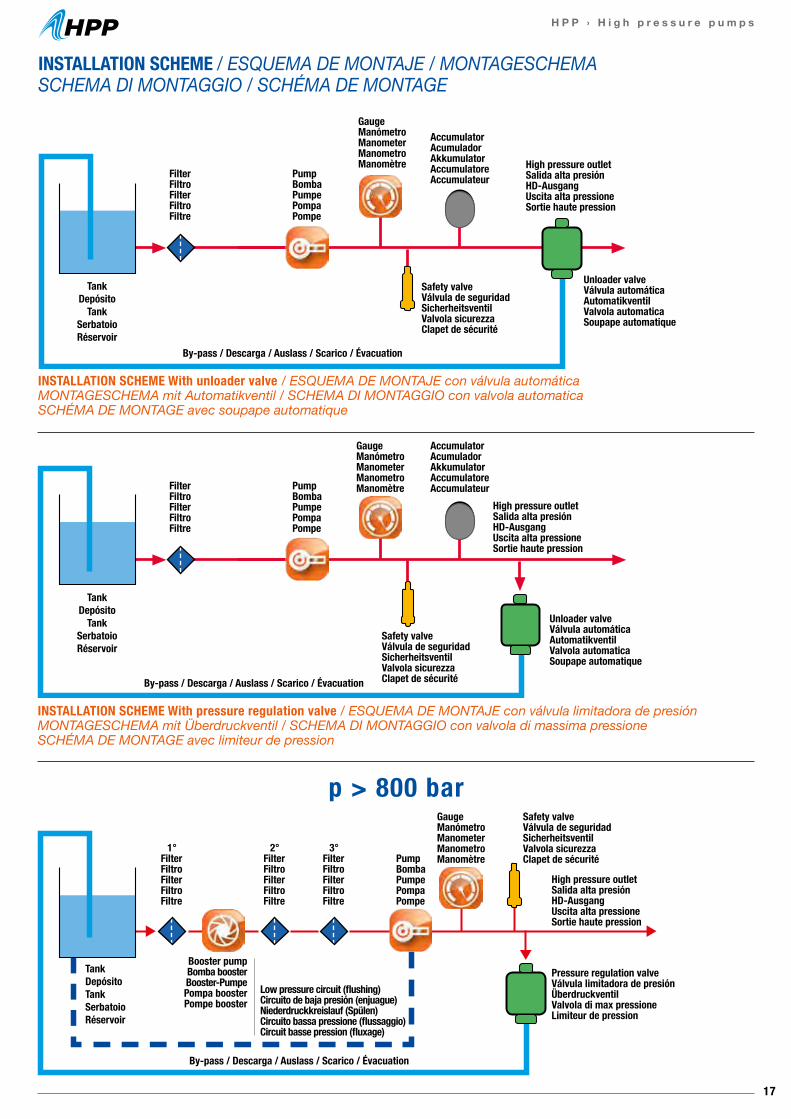
INSTALLATION SCHEME With unloader valve / ESQUEMA DE MONTAJE con válvula automáticaMONTAGESCHEMA mit Automatikventil / SCHEMA DI MONTAGGIO con valvola automaticaSCHÉMA DE MONTAGE avec soupape automatique
By-pass / Descarga / Auslass / Scarico / Évacuation
TankDepósito
TankSerbatoioRéservoir
FilterFiltroFilterFiltroFiltre
PumpBombaPumpePompaPompe
PumpBombaPumpePompaPompe
PumpBombaPumpePompaPompe
GaugeManómetroManometerManometroManomètre
AccumulatorAcumuladorAkkumulatorAccumulatoreAccumulateur
AccumulatorAcumuladorAkkumulatorAccumulatoreAccumulateur
High pressure outletSalida alta presiónHD-AusgangUscita alta pressioneSortie haute pression
Unloader valveVálvula automáticaAutomatikventilValvola automaticaSoupape automatique
Safety valveVálvula de seguridadSicherheitsventilValvola sicurezzaClapet de sécurité
INSTALLATION SCHEME With pressure regulation valve / ESQUEMA DE MONTAJE con válvula limitadora de presiónMONTAGESCHEMA mit Überdruckventil / SCHEMA DI MONTAGGIO con valvola di massima pressioneSCHÉMA DE MONTAGE avec limiteur de pression
TankDepósito
TankSerbatoioRéservoir
Safety valveVálvula de seguridadSicherheitsventilValvola sicurezzaClapet de sécurité
High pressure outletSalida alta presiónHD-AusgangUscita alta pressioneSortie haute pression
Unloader valveVálvula automáticaAutomatikventilValvola automaticaSoupape automatique
GaugeManómetroManometerManometroManomètre
INSTALLATION SCHEME / ESQUEMA DE MONTAJE / MONTAGESCHEMA SCHEMA DI MONTAGGIO / SCHÉMA DE MONTAGE
p > 800 barGaugeManómetroManometerManometroManomètre
Safety valveVálvula de seguridadSicherheitsventilValvola sicurezzaClapet de sécurité
Low pressure circuit (flushing)Circuito de baja presión (enjuague)Niederdruckkreislauf (Spülen)Circuito bassa pressione (flussaggio)Circuit basse pression (fluxage)
Booster pumpBomba boosterBooster-PumpePompa boosterPompe booster
TankDepósito TankSerbatoioRéservoir
Pressure regulation valveVálvula limitadora de presiónÜberdruckventilValvola di max pressioneLimiteur de pression
High pressure outletSalida alta presiónHD-AusgangUscita alta pressioneSortie haute pression
FilterFiltroFilterFiltroFiltre
1°FilterFiltroFilterFiltroFiltre
2°FilterFiltroFilterFiltroFiltre
3°FilterFiltroFilterFiltroFiltre
By-pass / Descarga / Auslass / Scarico / Évacuation
By-pass / Descarga / Auslass / Scarico / Évacuation
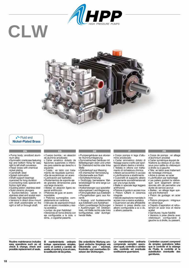
18
CLW
Corpo pompa in lega d’allu-minio anodizzato Carter simmetrico dotato di fissaggi sopra e sotto per spor-genza albero destra o sinistra Testata in ottone con tratta-mento di nichelatura chimica Albero ad eccentrici in acciaio Lubrificazione a sbattimento Cuscinetti di supporto albero ampiamente sovradimensionati per una lunga durata Bielle in speciale lega leggera antifrizione Pistone di guida in acciaio inox Pistoni tuffanti in ceramica integrale Valvole aspirazione mandata in acciaio inox e resina acetalica Guarnizioni ad alta affidabilità Versioni in presa diretta con albero configurabile a sx o dx, o albero passante.
La manutenzione ordinaria comprende semplici opera-zioni quali, controllo e cambio olio, controllo ed eventuale sostituzione guarnizioni.
Pumpengehäuse aus eloxier-ter Aluminiumlegierung Symmetrisches Gehäuse mitBefestigungen oben und unten für Überstand rechte oder linke Welle Zylinderkopf aus Messing mit chemischer Vernickelung Nockenwelle aus Stahl Schüttelschmierung Großzügig bemessene Wel-lenstützlager für eine lange Le-bensdauer Kolbenstangen aus spezieller reibungsloser Leichtlegierung Führungskolben aus Edelstahl Plungerkolben ganz aus Ke-ramik Ansaug- und Auslassventile aus Edelstahl und Azetalharz Sehr zuverlässige Dichtungen Ausführungen mit Direktan-trieb, mit Welle rechts oder links konfigurierbar, oder durchge-hende Welle.
Die ordentliche Wartung um-fasst einfache Vorgänge wie Ölkontrolle und - wechsel, Kontrolle und eventuelles Er-setzen der Dichtungen.
Pump body: anodized alumi-nium alloy Symmetric crankcase featuring top and bottom fixing for easy right to left shaft conversion Head: brass with chemical nickel plating Camshaft: steel Splash lubrication Shaft support bearings oversized for long duration Connecting rods: special anti-friction light alloy Guiding piston: stainless steel Solid ceramic plungers Suction/delivery valves in stainless steel and acetal resin Seals: high dependability Versions in direct drive mount with shaft positionable on the right or left or through shaft.
Routine maintenance includes easy operations such as: oil check & change, check and possible replacement of seals.
EN ES DE IT FR Cuerpo bomba : en aleación de aluminio anodizado Cárter simétrico dotado de fijaciones superiores e inferio-res para saliente eje derecho o izquierdo Culata : en latón con trata-miento de niquelado químico Eje de excéntricas: en acero Lubricación por barboteo Rodamientos de soporte eje de grandes dimensiones para una larga duración Bielas: en aleación ligera es-pecial antifricción Pistones de guía: en aceroinoxidable Pistones sumergidos: com-pletamente en cerámica Válvulas de aspiración/impul-sión en acero inoxidable y resi-na acetálica Juntas: de gran fiabilidad Versiones en toma directa coneje configurable a la izda. o dcha., o cigüeñal pasante.
El mantenimiento ordinario incluye operaciones simples, como el control y cambio de aceite, el control y, si es el caso, la sustitución de las juntas.
Corps de pompe : en alliage d’aluminium anodisé Carter symétrique équipé defixations au-dessus et au-des-sous pour saillie du vilebrequin à droite ou à gauche Tête : en laiton avec traitement de nickelage chimique. Arbre à cames: en acier Lubrification par barbotage Les paliers guidant le vilebre-quin sont largement dimen-sionnés afin de permettre une durée de service accrue Bielles : en alliage léger spé-cial anti-frottement Piston de guidage: en acier inox Pistons plongeurs : intégraux en céramique Clapets d’aspiration et refou-lement en acier inox et résine acétal Garnitures: haute fiabilité Versions à prise directe avec vilebrequin configurable à gauche ou à droite, ou passant.
L’entretien courant comprend de simples opérations telles que le contrôle et la vidange de l’huile, le contrôle et la substitution éventuelle des garnitures.
Fluid endNickel-Plated Brass
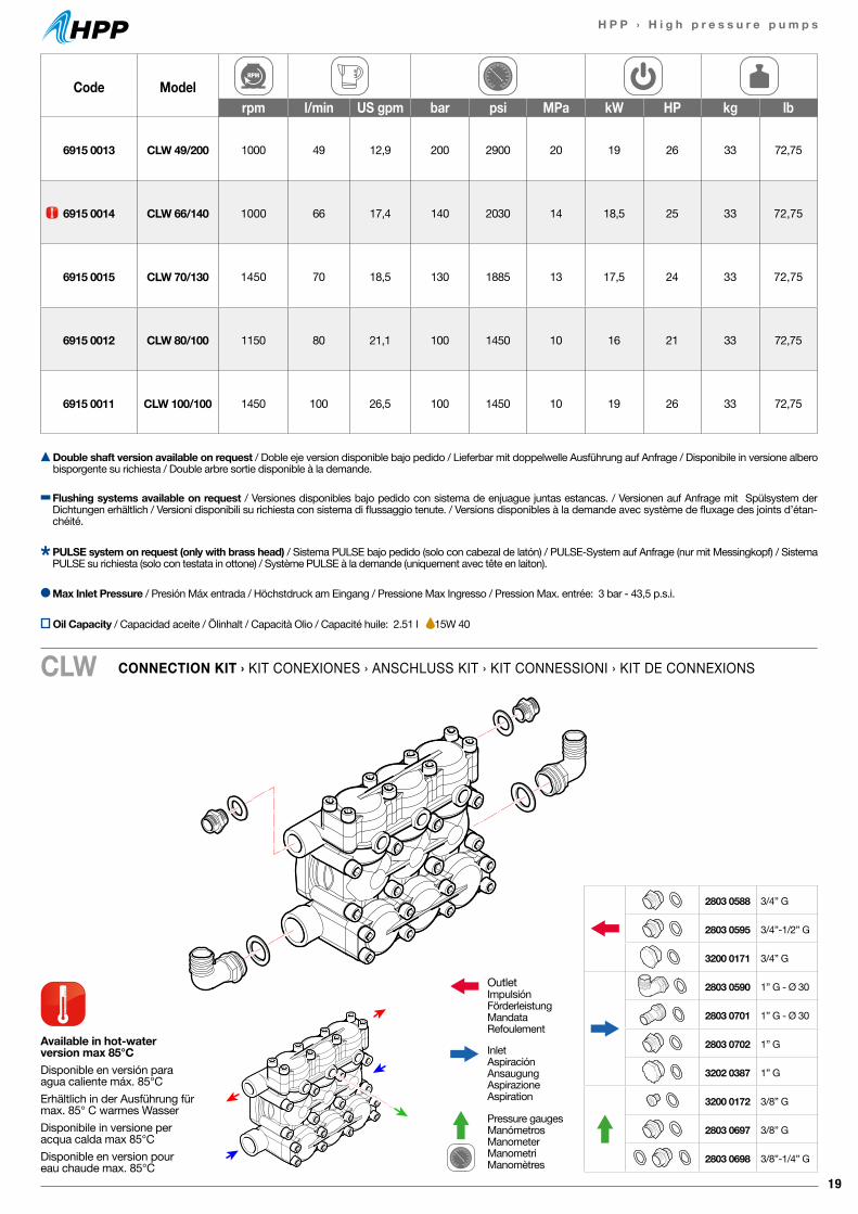
19
H P P › H i g h p r e s s u r e p u m p s
Code Modelrpm l/min US gpm bar psi MPa kW HP kg lb
6915 0013 CLW 49/200 1000 49 12,9 200 2900 20 19 26 33 72,75
6915 0014 CLW 66/140 1000 66 17,4 140 2030 14 18,5 25 33 72,75
6915 0015 CLW 70/130 1450 70 18,5 130 1885 13 17,5 24 33 72,75
6915 0012 CLW 80/100 1150 80 21,1 100 1450 10 16 21 33 72,75
6915 0011 CLW 100/100 1450 100 26,5 100 1450 10 19 26 33 72,75
CONNECTION KIT › KIT CONEXIONES › ANSCHLUSS KIT › KIT CONNESSIONI › KIT DE CONNEXIONSCLW
Available in hot-waterversion max 85°CDisponible en versión paraagua caliente máx. 85°CErhältlich in der Ausführung für max. 85° C warmes WasserDisponibile in versione per acqua calda max 85°CDisponible en version pour eau chaude max. 85°C
Double shaft version available on request / Doble eje version disponible bajo pedido / Lieferbar mit doppelwelle Ausführung auf Anfrage / Disponibile in versione albero bisporgente su richiesta / Double arbre sortie disponible à la demande.
Max Inlet Pressure / Presión Máx entrada / Höchstdruck am Eingang / Pressione Max Ingresso / Pression Max. entrée: 3 bar - 43,5 p.s.i.
Flushing systems available on request / Versiones disponibles bajo pedido con sistema de enjuague juntas estancas. / Versionen auf Anfrage mit Spülsystem der Dichtungen erhältlich / Versioni disponibili su richiesta con sistema di flussaggio tenute. / Versions disponibles à la demande avec système de fluxage des joints d’étan-chéité.
PULSE system on request (only with brass head) / Sistema PULSE bajo pedido (solo con cabezal de latón) / PULSE-System auf Anfrage (nur mit Messingkopf) / Sistema PULSE su richiesta (solo con testata in ottone) / Système PULSE à la demande (uniquement avec tête en laiton).
OutletImpulsiónFörderleistungMandataRefoulement
InletAspiraciónAnsaugungAspirazioneAspiration
Pressure gaugesManómetrosManometerManometriManomètres
2803 0588 3/4” G
2803 0595 3/4”-1/2” G
3200 0171 3/4” G
2803 0590 1” G - Ø 30
2803 0701 1” G - Ø 30
2803 0702 1” G
3202 0387 1” G
3200 0172 3/8” G
2803 0697 3/8” G
2803 0698 3/8”-1/4” G
Oil Capacity / Capacidad aceite / Ölinhalt / Capacità Olio / Capacité huile: 2.51 l 15W 40
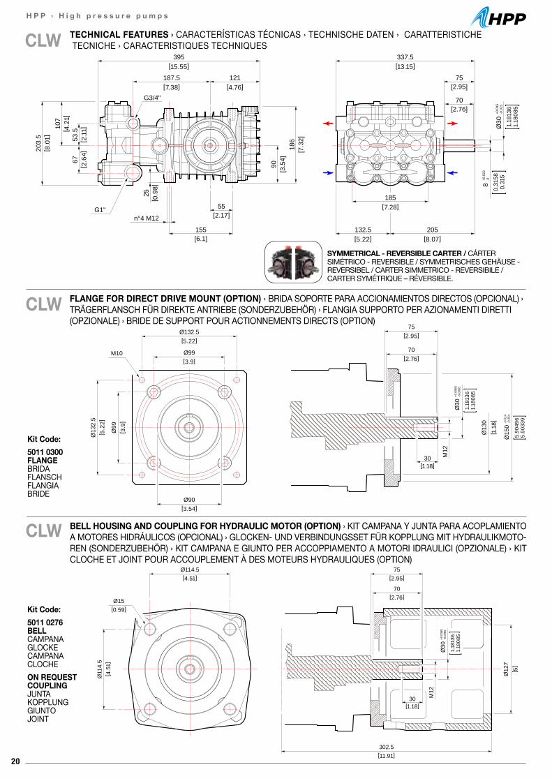
20
H P P › H i g h p r e s s u r e p u m p s
75[2.95]
Ø114.5[4.51]
302.5 [11.91]
Ø11
4.5
[ 4.5
1]
Ø15[0.59]
70[2.76]
30[1.18]
M12
Ø30
+0.0
065
-0.0
065
1.18
136
1.18
085
[ 5]
Ø12
7
75[2.95]Ø132.5
[5.22]
Ø99[3.9]
Ø90[3.54]
[ 1.1
8]
Ø13
2.5
[ 5.2
2]
Ø99
[ 3.9
]
70[2.76]
30[1.18]
M12
M10
Ø30
+0.0
065
-0.0
065
1.18
136
1.18
085
Ø15
0-0
.014
-0.0
54
5.90
496
5.90
339
Ø13
0
[2.95]75
[2.76]70
[2.17]55
[6.1]155
n°4 M12
[3.5
4]90
[7.3
2]18
6
[ 8.0
1]20
3.5
395[15.55]
337.5[13.15]
132.5[5.22]
205[8.07]
185[7.28]
187.5[7.38]
121[4.76]
[ 2.6
4]67
[ 2.1
1]53
.5[ 4.2
1]10
7
8+0
.022
-0
0.31
580.
315
Ø30
+0.0
15-0
.015
1.18
136
1.18
085
G3/4"
G1"
[ 0.9
8]25
CLW
SYMMETRICAL - REVERSIBLE CARTER / CÁRTER SIMÉTRICO - REVERSIBLE / SYMMETRISCHES GEHÄUSE - REVERSIBEL / CARTER SIMMETRICO - REVERSIBILE / CARTER SYMÉTRIQUE – RÉVERSIBLE.
CLW
BELL HOUSING AND COUPLING FOR HYDRAULIC MOTOR (OPTION) › KIT CAMPANA Y JUNTA PARA ACOPLAMIENTO A MOTORES HIDRÁULICOS (OPCIONAL) › GLOCKEN- UND VERBINDUNGSSET FÜR KOPPLUNG MIT HYDRAULIKMOTO-REN (SONDERZUBEHÖR) › KIT CAMPANA E GIUNTO PER ACCOPPIAMENTO A MOTORI IDRAULICI (OPZIONALE) › KIT CLOCHE ET JOINT POUR ACCOUPLEMENT À DES MOTEURS HYDRAULIQUES (OPTION)
CLW
FLANGE FOR DIRECT DRIVE MOUNT (OPTION) › BRIDA SOPORTE PARA ACCIONAMIENTOS DIRECTOS (OPCIONAL) › TRÄGERFLANSCH FÜR DIREKTE ANTRIEBE (SONDERZUBEHÖR) › FLANGIA SUPPORTO PER AZIONAMENTI DIRETTI (OPZIONALE) › BRIDE DE SUPPORT POUR ACTIONNEMENTS DIRECTS (OPTION)
Kit Code:5011 0276 BELLCAMPANAGLOCKECAMPANACLOCHEON REQUEST COUPLINGJUNTAKOPPLUNG GIUNTOJOINT
Kit Code:5011 0300 FLANGEBRIDAFLANSCH FLANGIABRIDE
TECHNICAL FEATURES › CARACTERÍSTICAS TÉCNICAS › TECHNISCHE DATEN › CARATTERISTICHE TECNICHE › CARACTERISTIQUES TECHNIQUES
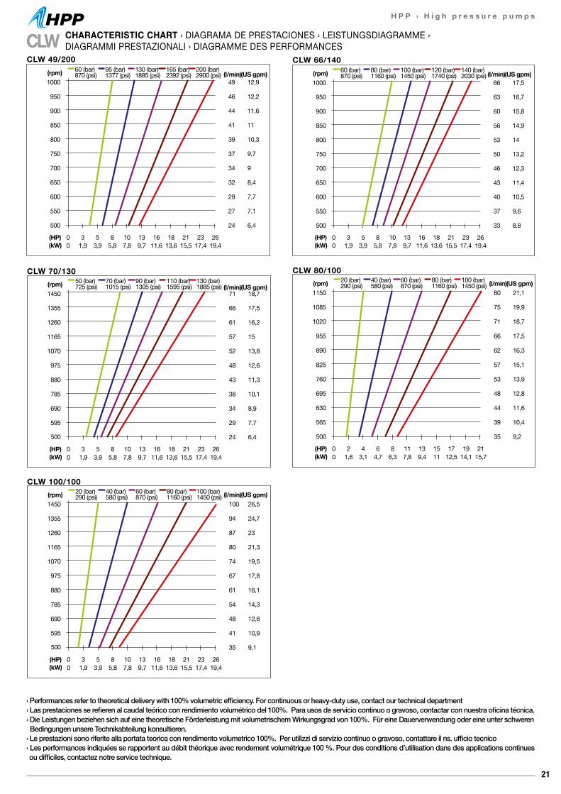
21
H P P › H i g h p r e s s u r e p u m p s
1450
1355
1260
1165
1070
975
880
785
690
595
500
100
94
87
80
74
67
61
54
48
41
35
(l/min)26,5
24,7
23
21,3
19,5
17,8
16,1
14,3
12,6
10,9
9,1
0 3 5 8 10 13 16 18 21 23 260 1,9 3,9 5,8 7,8 9,7 11,6 13,6 15,5 17,4 19,4
(HP)(kW)
(rpm) 20 (bar)290 (psi)
40 (bar)580 (psi)
60 (bar)870 (psi)
80 (bar)1160 (psi)
100 (bar)1450 (psi) (US gpm)
CLW 100/100
(l/min)(US gpm)
0 3 5 8 10 13 16 18 21 23 260 1,9 3,9 5,8 7,8 9,7 11,6 13,6 15,5 17,4 19,4
(HP)(kW)
1450
1355
1260
1165
1070
975
880
785
690
595
500
71
66
61
57
52
48
43
38
34
29
24
18,7
17,5
16,2
15
13,8
12,6
11,3
10,1
8,9
7,7
6,4
(rpm) 50 (bar)725 (psi)
70 (bar)1015 (psi)
90 (bar)1305 (psi)
110 (bar)1595 (psi)
130 (bar)1885 (psi)
CLW 70/130(l/min)(US gpm)
1150
1085
1020
955
890
825
760
695
630
565
500
80
75
71
66
62
57
53
48
44
39
35
21,1
19,9
18,7
17,5
16,3
15,1
13,9
12,8
11,6
10,4
9,2
0 2 4 6 8 11 13 15 17 19 210 1,6 3,1 4,7 6,3 7,8 9,4 11 12,5 14,1 15,7
(HP)(kW)
(rpm) 20 (bar)290 (psi)
40 (bar)580 (psi)
60 (bar)870 (psi)
80 (bar)1160 (psi)
100 (bar)1450 (psi)
CLW 80/100
(l/min)(US gpm)1000
950
900
850
800
750
700
650
600
550
500
49
46
44
41
39
37
34
32
29
27
24
12,9
12,2
11,6
11
10,3
9,7
9
8,4
7,7
7,1
6,4
0 3 5 8 10 13 16 18 21 23 260 1,9 3,9 5,8 7,8 9,7 11,6 13,6 15,5 17,4 19,4
(HP)(kW)
(rpm) 60 (bar)870 (psi)
95 (bar)1377 (psi)
130 (bar)1885 (psi)
165 (bar)2392 (psi)
200 (bar)2900 (psi)
CLW 49/200
(l/min)(US gpm)1000
950
900
850
800
750
700
650
600
550
500
66
63
60
56
53
50
46
43
40
37
33
17,5
16,7
15,8
14,9
14
13,2
12,3
11,4
10,5
9,6
8,8
0 3 5 8 10 13 16 18 21 23 260 1,9 3,9 5,8 7,8 9,7 11,6 13,6 15,5 17,4 19,4
(HP)(kW)
(rpm) 60 (bar)870 (psi)
80 (bar)1160 (psi)
100 (bar)1450 (psi)
120 (bar)1740 (psi)
140 (bar)2030 (psi)
CLW 66/140
› Performances refer to theoretical delivery with 100% volumetric efficiency. For continuous or heavy-duty use, contact our technical department› Las prestaciones se refieren al caudal teórico con rendimiento volumétrico del 100%. Para usos de servicio continuo o gravoso, contactar con nuestra oficina técnica.› Die Leistungen beziehen sich auf eine theoretische Förderleistung mit volumetrischem Wirkungsgrad von 100%. Für eine Dauerverwendung oder eine unter schweren Bedingungen unsere Technikabteilung konsultieren.› Le prestazioni sono riferite alla portata teorica con rendimento volumetrico 100%. Per utilizzi di servizio continuo o gravoso, contattare il ns. ufficio tecnico› Les performances indiquées se rapportent au débit théorique avec rendement volumétrique 100 %. Pour des conditions d’utilisation dans des applications continues ou difficiles, contactez notre service technique.
CLW CHARACTERISTIC CHART › DIAGRAMA DE PRESTACIONES › LEISTUNGSDIAGRAMME ›DIAGRAMMI PRESTAZIONALI › DIAGRAMME DES PERFORMANCES
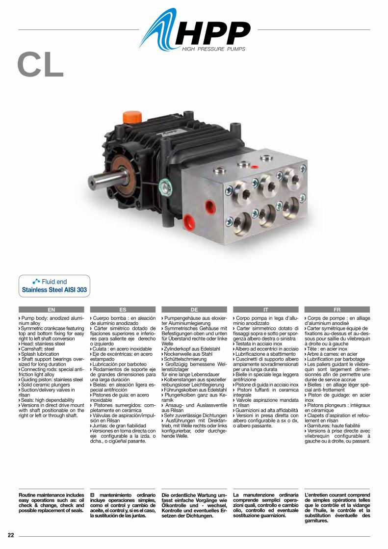
22
CL
EN ES DE IT FR Corpo pompa in lega d’allu-minio anodizzato Carter simmetrico dotato di fissaggi sopra e sotto per spor-genza albero destra o sinistra Testata in acciaio inox Albero ad eccentrici in acciaio Lubrificazione a sbattimento Cuscinetti di supporto albero ampiamente sovradimensionati per una lunga durata Bielle in speciale lega leggera antifrizione Pistone di guida in acciaio inox Pistoni tuffanti in ceramica integrale Valvole aspirazione mandata in rilsan Guarnizioni ad alta affidabilità Versioni in presa diretta con albero configurabile a sx o dx, o albero passante.
La manutenzione ordinaria comprende semplici opera-zioni quali, controllo e cambio olio, controllo ed eventuale sostituzione guarnizioni.
Pump body: anodized alumi-nium alloy Symmetric crankcase featuring top and bottom fixing for easy right to left shaft conversion Head: stainless steel Camshaft: steel Splash lubrication Shaft support bearings over-sized for long duration Connecting rods: special anti-friction light alloy Guiding piston: stainless steel Solid ceramic plungers Suction/delivery valves inrilsan Seals: high dependability Versions in direct drive mount with shaft positionable on the right or left or through shaft.
Routine maintenance includes easy operations such as: oil check & change, check and possible replacement of seals.
Cuerpo bomba : en aleación de aluminio anodizado Cárter simétrico dotado de fijaciones superiores e inferio-res para saliente eje derecho o izquierdo Culata : en acero inoxidable Eje de excéntricas: en aceroestampado Lubricación por barboteo Rodamientos de soporte eje de grandes dimensiones para una larga duración Bielas: en aleación ligera es-pecial antifricción Pistones de guía: en aceroinoxidable Pistones sumergidos: com-pletamente en cerámica Válvulas de aspiración/impul-sión en Rilsan Juntas: de gran fiabilidad Versiones en toma directa coneje configurable a la izda. o dcha., o cigüeñal pasante.
El mantenimiento ordinario incluye operaciones simples, como el control y cambio de aceite, el control y, si es el caso, la sustitución de las juntas.
Pumpengehäuse aus eloxier-ter Aluminiumlegierung Symmetrisches Gehäuse mit Befestigungen oben und unten für Überstand rechte oder linke Welle Zylinderkopf aus Edelstahl Nockenwelle aus Stahl Schüttelschmierung Großzügig bemessene Wel-lenstützlagerfür eine lange Lebensdauer Kolbenstangen aus spezieller reibungsloser Leichtlegierung Führungskolben aus Edelstahl Plungerkolben ganz aus Ke-ramik Ansaug- und Auslassventile aus Rilsan Sehr zuverlässige Dichtungen Ausführungen mit Direktan-trieb, mit Welle rechts oder links konfigurierbar, oder durchge-hende Welle.
Die ordentliche Wartung um-fasst einfache Vorgänge wie Ölkontrolle und - wechsel, Kontrolle und eventuelles Er-setzen der Dichtungen.
Corps de pompe : en alliage d’aluminium anodisé Carter symétrique équipé defixations au-dessus et au-des-sous pour saillie du vilebrequin à droite ou à gauche Tête : en acier inox Arbre à cames: en acier Lubrification par barbotage Les paliers guidant le vilebre-quin sont largement dimen-sionnés afin de permettre une durée de service accrue Bielles : en alliage léger spé-cial anti-frottement Piston de guidage: en acier inox Pistons plongeurs : intégraux en céramique Clapets d’aspiration et refou-lement en rilsan Garnitures: haute fiabilité Versions à prise directe avec vilebrequin configurable à gauche ou à droite, ou passant.
L’entretien courant comprend de simples opérations telles que le contrôle et la vidange de l’huile, le contrôle et la substitution éventuelle des garnitures.
Fluid endStainless Steel AISI 303
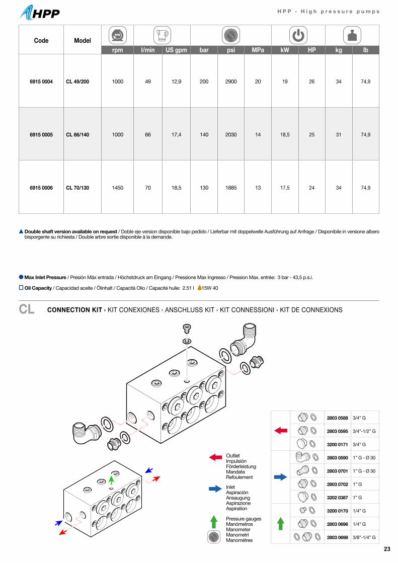
23
H P P › H i g h p r e s s u r e p u m p s
Code Modelrpm l/min US gpm bar psi MPa kW HP kg lb
6915 0004 CL 49/200 1000 49 12,9 200 2900 20 19 26 34 74,9
6915 0005 CL 66/140 1000 66 17,4 140 2030 14 18,5 25 31 74,9
6915 0006 CL 70/130 1450 70 18,5 130 1885 13 17,5 24 34 74,9
CONNECTION KIT › KIT CONEXIONES › ANSCHLUSS KIT › KIT CONNESSIONI › KIT DE CONNEXIONSCL
Double shaft version available on request / Doble eje version disponible bajo pedido / Lieferbar mit doppelwelle Ausführung auf Anfrage / Disponibile in versione albero bisporgente su richiesta / Double arbre sortie disponible à la demande.
Max Inlet Pressure / Presión Máx entrada / Höchstdruck am Eingang / Pressione Max Ingresso / Pression Max. entrée: 3 bar - 43,5 p.s.i.
OutletImpulsiónFörderleistungMandataRefoulement
InletAspiraciónAnsaugungAspirazioneAspiration
Pressure gaugesManómetrosManometerManometriManomètres
2803 0588 3/4” G
2803 0595 3/4”-1/2” G
3200 0171 3/4” G
2803 0590 1” G - Ø 30
2803 0701 1” G - Ø 30
2803 0702 1” G
3202 0387 1” G
3200 0170 1/4” G
2803 0696 1/4” G
2803 0698 3/8”-1/4” G
Oil Capacity / Capacidad aceite / Ölinhalt / Capacità Olio / Capacité huile: 2.51 l 15W 40
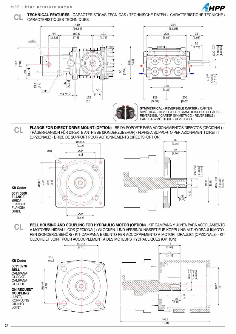
24
H P P › H i g h p r e s s u r e p u m p s
75[2.95]
Ø114.5[4.51]
302.5 [11.91]
Ø11
4.5
[ 4.5
1]
Ø15[0.59]
70[2.76]
30[1.18]
M12
Ø30
+0.0
065
-0.0
065
1.18
136
1.18
085
[ 5]
Ø12
7
75[2.95]Ø132.5
[5.22]
Ø99[3.9]
Ø90[3.54]
[ 1.1
8]
Ø13
2.5
[ 5.2
2]
Ø99
[ 3.9
]
70[2.76]
30[1.18]
M12
M10
Ø30
+0.0
065
-0.0
065
1.18
136
1.18
085
Ø15
0-0
.014
-0.0
54
5.90
496
5.90
339
Ø13
0
BELL HOUSING AND COUPLING FOR HYDRAULIC MOTOR (OPTION) › KIT CAMPANA Y JUNTA PARA ACOPLAMIENTO A MOTORES HIDRÁULICOS (OPCIONAL) › GLOCKEN- UND VERBINDUNGSSET FÜR KOPPLUNG MIT HYDRAULIKMOTO-REN (SONDERZUBEHÖR) › KIT CAMPANA E GIUNTO PER ACCOPPIAMENTO A MOTORI IDRAULICI (OPZIONALE) › KIT CLOCHE ET JOINT POUR ACCOUPLEMENT À DES MOTEURS HYDRAULIQUES (OPTION)
CL
[2.95]75
[2.76]70
[8.07]205
[5.08]129
[7.28]185
[16.14]410
[13.15]334
[7.5]190.5
[2.52]64
[8.86]225
[4.76]121
[2.17]55
[6.1]155
n°4 M12
[3.5
4]90
[7.3
2]18
6
[ 7.0
9]18
0
[ 3.2
7]83
[ 1.4
]35
.5
8+0
.022
-0
0.31
580.
315
Ø30
+0.0
15-0
.015
1.18
136
1.18
085
G3/4"
G1"
[ 0.9
8]25
CL
SYMMETRICAL - REVERSIBLE CARTER / CÁRTER SIMÉTRICO - REVERSIBLE / SYMMETRISCHES GEHÄUSE - REVERSIBEL / CARTER SIMMETRICO - REVERSIBILE / CARTER SYMÉTRIQUE – RÉVERSIBLE.
CL FLANGE FOR DIRECT DRIVE MOUNT (OPTION) › BRIDA SOPORTE PARA ACCIONAMIENTOS DIRECTOS (OPCIONAL) › TRÄGERFLANSCH FÜR DIREKTE ANTRIEBE (SONDERZUBEHÖR) › FLANGIA SUPPORTO PER AZIONAMENTI DIRETTI (OPZIONALE) › BRIDE DE SUPPORT POUR ACTIONNEMENTS DIRECTS (OPTION)
Kit Code:5011 0276 BELL CAMPANAGLOCKE CAMPANACLOCHEON REQUEST COUPLING JUNTAKOPPLUNG GIUNTOJOINT
Kit Code:5011 0300 FLANGE BRIDAFLANSCHFLANGIABRIDE
TECHNICAL FEATURES › CARACTERÍSTICAS TÉCNICAS › TECHNISCHE DATEN › CARATTERISTICHE TECNICHE ›CARACTERISTIQUES TECHNIQUES
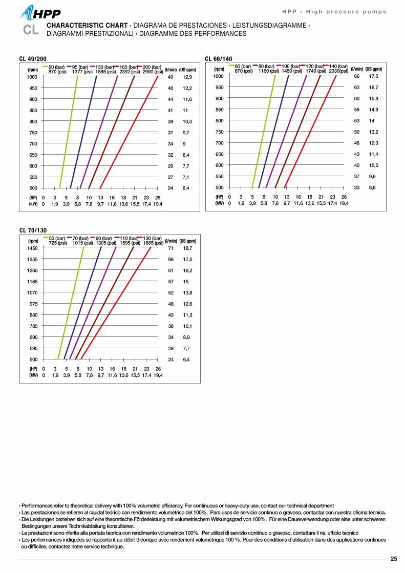
25
H P P › H i g h p r e s s u r e p u m p s
CHARACTERISTIC CHART › DIAGRAMA DE PRESTACIONES › LEISTUNGSDIAGRAMME ›DIAGRAMMI PRESTAZIONALI › DIAGRAMME DES PERFORMANCESCL
1000
950
900
850
800
750
700
650
600
550
500
49
46
44
41
39
37
34
32
29
27
24
(l/min)12,9
12,2
11,6
11
10,3
9,7
9
8,4
7,7
7,1
6,4
0 3 5 8 10 13 16 18 21 23 260 1,9 3,9 5,8 7,8 9,7 11,6 13,6 15,5 17,4 19,4
(HP)(kW)
(rpm) 60 (bar)870 (psi)
95 (bar)1377 (psi)
130 (bar)1885 (psi)
165 (bar)2392 (psi)
200 (bar)2900 (psi) (US gpm)
CL 49/200
1000
950
900
850
800
750
700
650
600
550
500
66
63
60
56
53
50
46
43
40
37
33
(l/min)17,5
16,7
15,8
14,9
14
13,2
12,3
11,4
10,5
9,6
8,8
0 3 5 8 10 13 16 18 21 23 260 1,9 3,9 5,8 7,8 9,7 11,6 13,6 15,5 17,4 19,4
(HP)(kW)
(rpm) 60 (bar)870 (psi)
80 (bar)1160 (psi)
100 (bar)1450 (psi)
120 (bar)1740 (psi)
140 (bar)2030(psi) (US gpm)
CL 66/140
1450
1355
1260
1165
1070
975
880
785
690
595
500
71
66
61
57
52
48
43
38
34
29
24
(l/min)18,7
17,5
16,2
15
13,8
12,6
11,3
10,1
8,9
7,7
6,4
0 3 5 8 10 13 16 18 21 23 260 1,9 3,9 5,8 7,8 9,7 11,6 13,6 15,5 17,4 19,4
(HP)(kW)
(rpm) 50 (bar)725 (psi)
70 (bar)1015 (psi)
90 (bar)1305 (psi)
110 (bar)1595 (psi)
130 (bar)1885 (psi) (US gpm)
CL 70/130
› Performances refer to theoretical delivery with 100% volumetric efficiency. For continuous or heavy-duty use, contact our technical department› Las prestaciones se refieren al caudal teórico con rendimiento volumétrico del 100%. Para usos de servicio continuo o gravoso, contactar con nuestra oficina técnica.› Die Leistungen beziehen sich auf eine theoretische Förderleistung mit volumetrischem Wirkungsgrad von 100%. Für eine Dauerverwendung oder eine unter schweren Bedingungen unsere Technikabteilung konsultieren.› Le prestazioni sono riferite alla portata teorica con rendimento volumetrico 100%. Per utilizzi di servizio continuo o gravoso, contattare il ns. ufficio tecnico› Les performances indiquées se rapportent au débit théorique avec rendement volumétrique 100 %. Pour des conditions d’utilisation dans des applications continues ou difficiles, contactez notre service technique.
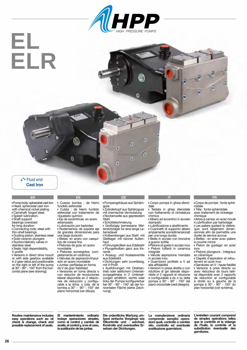
26
ELELR
EN ES DE IT FR Corpo pompa in ghisa sferoi-dale Testata in ghisa sferoidale con trattamento di nichelatura chimica Albero ad eccentrici in acciaio stampato Lubrificazione a sbattimento Cuscinetti di supporto albero ampiamente sovradimensionati per una lunga durata Bielle in acciaio con bronzine a guscio sottile Pistone di guida in acciaio inox Pistoni tuffanti in ceramica integrale Valvole aspirazione mandata in acciaio inox Guarnizioni profilate a V ad alta affidabilità Versioni in presa diretta o con riduttore di giri laterale dispo-nibile in 2 rapporti di riduzione e configurabile a dx o sx della pompa a 30° - 90° - 150° dal piano orizzontale (vedi disegno).
La manutenzione ordinaria comprende semplici opera-zioni quali, controllo e cambio olio, controllo ed eventuale sostituzione guarnizioni.
Pump body: spheroidal cast iron Head: spheroidal cast ironwith chemical nickel plating Camshaft: forged steel. Splash lubrication. Shaft support bearings oversizedfor long duration Connecting rods: steel withthin-shell bearings Guiding piston: stainless steel Solid ceramic plungers Suction/delivery valves instainless steel Seals: high dependability, V profile Versions in direct drive mount or with side gearbox available in 2 gear ratios and positionable on the right or left of the pump at 30° - 90° - 150° from the hori-zontal plane (see drawing).
Routine maintenance includes easy operations such as: oil check & change, check and possible replacement of seals.
Cuerpo bomba : de hierro fundido esferoidal Culata : de hierro fundido esferoidal con tratamiento de niquelado químico Eje de excéntricas: en aceroestampado Lubricación por barboteo Rodamientos de soporte eje de grandes dimensiones para una larga duración Bielas: en acero con casqui-llos de coraza fina Pistones de guía: en aceroinoxidable Pistones sumergidos: com-pletamente en cerámica Válvulas de aspiración/impul-sión en acero inoxidable Juntas: perfiladas en forma de V de gran fiabilidad Versiones en toma directa o con reductor de revoluciones lateral disponible en 2 relacio-nes de reducción y configu-rable a la dcha. o izda. de la bomba a 30° - 90° - 150° del plano horizontal (ver dibujo).
El mantenimiento ordinario incluye operaciones simples, como el control y cambio de aceite, el control y, si es el caso, la sustitución de las juntas.
Pumpengehäuse aus Sphäro-guss Zylinderkopf aus Sphärogussmit chemischer Vernickelung Nockenwelle aus gepresstem Stahl Schüttelschmierung Großzügig bemessene Wel-lenstützlager für eine lange Le-bensdauer Kolbenstangen aus Stahl mit Gleitlager mit dünner Außen-haut Führungskolben aus Edelstahl Plungerkolben ganz aus Ke-ramik Ansaug- und Auslassventile aus Edelstahl Dichtungen: sehr zuverlässig, mit V-Profil Ausführungen mit Direktan-trieb oder seitlichem Unterset-zungsgetriebe in 2 Unterset-zungen erhältlich, rechts oder links der Pumpe konfigurierbarbei 30° - 90° - 150° ab der ho-rizontalen Fläche (siehe Zeich-nung).
Die ordentliche Wartung um-fasst einfache Vorgänge wie Ölkontrolle und - wechsel, Kontrolle und eventuelles Er-setzen der Dichtungen.
Corps de pompe : fonte sphé-roïdale Tête : fonte sphéroïdaleavec traitement de nickelagechimique Arbre à cames: en acier moulé Lubrification par barbotage Les paliers guidant le vilebre-quin sont largement dimen-sionnés afin de permettre une durée de service accrue Bielles : en acier avec paliers à couche mince Piston de guidage: en acier inox Pistons plongeurs : intégraux en céramique Clapets d’aspiration et refou-lement en acier inox Garnitures: en V - haute fiabilité Versions à prise directe ou avec réducteur de tours laté-ral disponible avec 2 rapports de réduction et configurable à droite ou à gauche de la pompe à 30° - 90° - 150° du plan horizontal (voir schéma).
L’entretien courant comprend de simples opérations telles que le contrôle et la vidange de l’huile, le contrôle et la substitution éventuelle des garnitures.
Fluid endCast Iron

27
H P P › H i g h p r e s s u r e p u m p s
CONNECTION KIT › KIT CONEXIONES › ANSCHLUSS KIT › KIT CONNESSIONI › KIT DE CONNEXIONSEL / ELR
0608 0053 Valve release kitKit desbloqueo valvulaKit zur entsperrung der ventilKit sblocco valvolaKit de deblocage de soupape
Code Modelrpm l/min US gpm bar psi MPa kW HP kg lb
6905 0006 EL 84/190 1000 84 22,2 190 2755 19 31,6 43 88 1946908 0006 ELR 84/190 1500 84 22,2 190 2755 19 31,6 43 105 231,46908 0012 ELR 84/190 1900 84 22,2 190 2755 19 31,6 43 105 231,4
6905 0001 EL 102/160 1000 102 27 160 2320 16 31,6 43 88 1946908 0001 ELR 102/160 1500 102 27 160 2320 16 31,6 43 105 231,46908 0007 ELR 102/160 1900 102 27 160 2320 16 31,6 43 105 231,4
6905 0002 EL 122/130 1000 122 32,2 130 1885 13 31,6 43 88 1946908 0002 ELR 122/130 1500 122 32,2 130 1885 13 31,6 43 105 231,46908 0008 ELR 122/130 1900 122 32,2 130 1885 13 31,6 43 105 231,4
6905 0003 EL 128/120 850 128 33,8 120 1740 12 29,4 40 88 1946908 0003 ELR 128/120 1275 128 33,8 120 1740 12 29,4 40 105 231,46908 0009 ELR 128/120 1615 128 33,8 120 1740 12 29,4 40 105 231,4
6905 0004 EL 152/100 800 152 40,1 100 1450 10 29,4 40 88 1946908 0004 ELR 152/100 1200 152 40,1 100 1450 10 29,4 40 105 231,46908 0010 ELR 152/100 1520 152 40,1 100 1450 10 29,4 40 105 231,4
6905 0005 EL 164/90 700 164 43,3 90 1305 9 29,4 40 88 1946908 0005 ELR 164/90 1050 164 43,3 90 1305 9 29,4 40 105 231,46908 0011 ELR 164/90 1330 164 43,3 90 1305 9 29,4 40 105 231,4
Max Inlet Pressure / Presión Máx entrada / Höchstdruck am Eingang / Pressione Max Ingresso / Pression Max. entrée: 3 bar - 43,5 p.s.i.
PULSE system on request / Sistema PULSE bajo pedido / PULSE-System auf Anfrage / Sistema PULSE su richiesta / Système PULSE à la demande.
OutletImpulsiónFörderleistungMandataRefoulement
InletAspiraciónAnsaugungAspirazioneAspiration
Pressure gaugesManómetrosManometerManometriManomètres
2803 0591 1” G
2803 0597 1” - 3/4” G
2803 0598 1” - 1/2” G
3202 0387 1” G
2803 0594 1”1/2 G - Ø 40
2803 0601 1”1/2 G - Ø 50
2803 0703 1”1/2 G
3200 0174 1”1/2 G
3200 0170 1/4” G
2803 0696 1/4” G
2803 0698 3/8”-1/4” G
Oil Capacity / Capacidad aceite / Ölinhalt / Capacità Olio / Capacité huile: 4.00 l 15W 40Oil Capacity with Gearbox / Capacidad aceite con Reductor / Ölinhalt mit Untersetzungsgetriebe / Capacità Olio con Riduttore / Capacité huile avec Réducteur: 4.53 l 15W 40
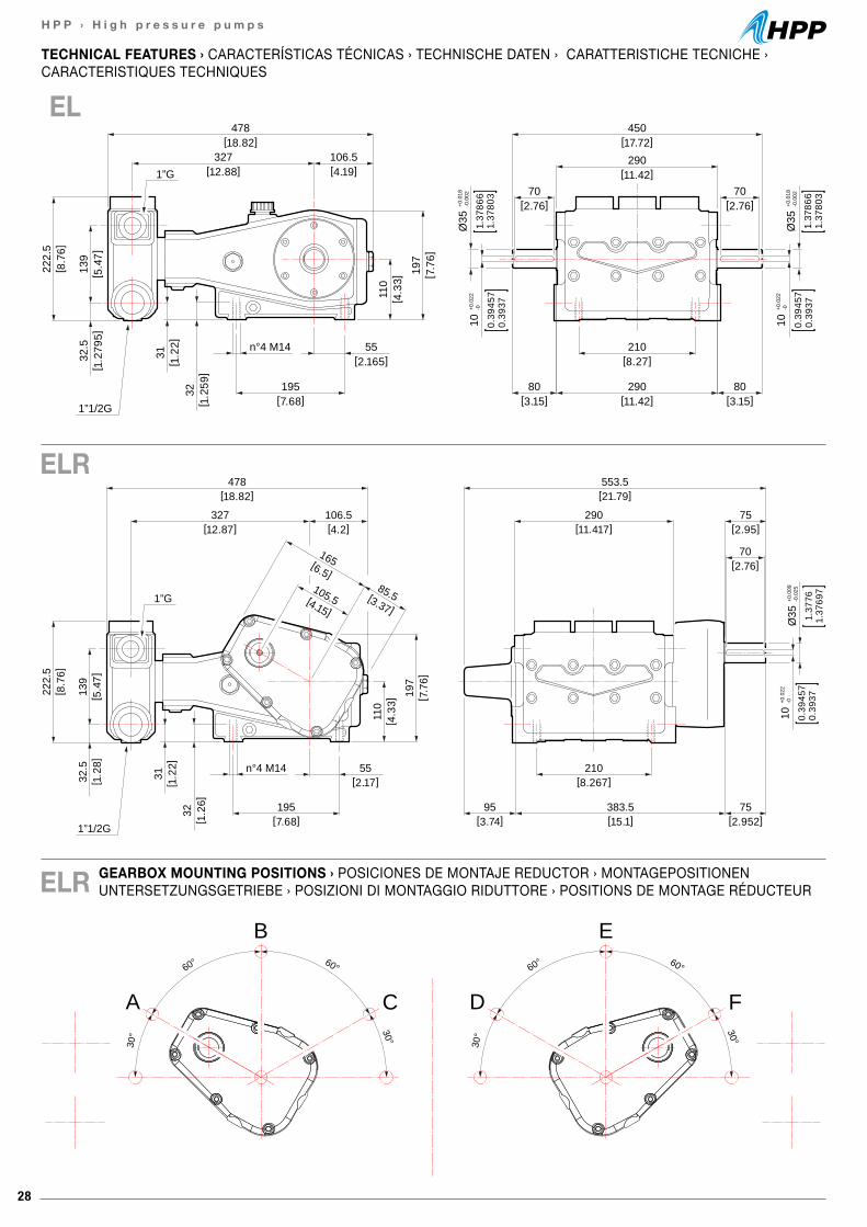
28
H P P › H i g h p r e s s u r e p u m p s
110
[ 4.3
3]
32[ 1
.26]
31[ 1
.22]
139
[ 5.4
7]32
.5[ 1
.28]
222.
5[ 8
.76]
197
[ 7.7
6]
[18.82]478
[12.87]327
[7.68]195
1”1/2G
1”G
[2.17]55n°4 M14
[2.952]75
[15.1]383.5
[3.74]95
[11.417]290
[21.79]553.5
[8.267]210
10+0
.022
-0
0.39
457
0.39
371.
3776
1.37
697
Ø35
+0.0
09-0
.025
[4.2]106.5
[6.5]
165
[4.15]
105.5 [3.37]
85.5
[2.95]75
[2.76]70
110
[ 4.3
3]
32[ 1
.259
]
31[ 1
.22]
139
[ 5.4
7]32
.5[ 1
.279
5]
222.
5[ 8
.76]
197
[ 7.7
6]
[18.82]478
[12.88]327
[4.19]106.5
[7.68]195
1”1/2G
1”G
[2.165]55n°4 M14
[3.15]80
[3.15]80
[2.76]70
[2.76]70
[11.42]290
[11.42]290
[17.72]450
[8.27]210
10+0
.022
-0
0.39
457
0.39
371.
3786
61.
3780
3
Ø35
+0.0
18-0
.002
10+0
.022
-0
0.39
457
0.39
37
1.37
866
1.37
803
Ø35
+0.0
18-0
.002
GEARBOX MOUNTING POSITIONS › POSICIONES DE MONTAJE REDUCTOR › MONTAGEPOSITIONEN UNTERSETZUNGSGETRIEBE › POSIZIONI DI MONTAGGIO RIDUTTORE › POSITIONS DE MONTAGE RÉDUCTEUR
TECHNICAL FEATURES › CARACTERÍSTICAS TÉCNICAS › TECHNISCHE DATEN › CARATTERISTICHE TECNICHE ›CARACTERISTIQUES TECHNIQUES
EL
ELR
ELR
60° 60°
30° 30°
A
B
C
60° 60°
30° 30°
D
E
F
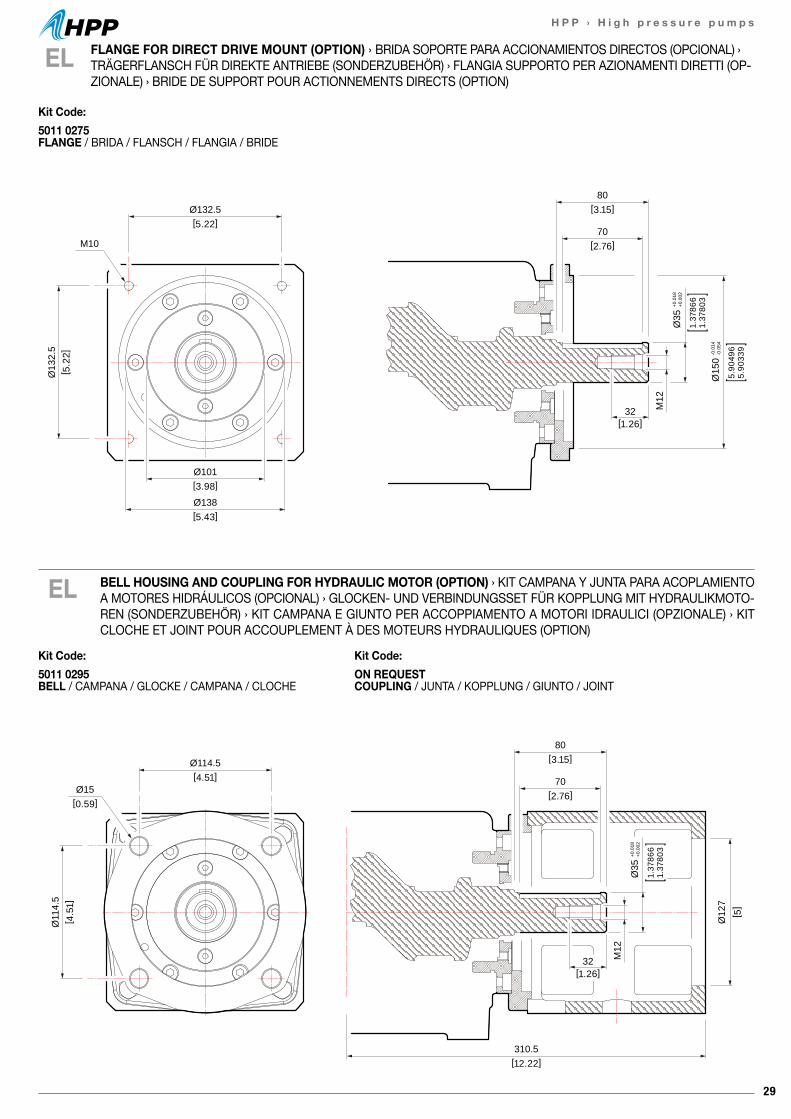
29
H P P › H i g h p r e s s u r e p u m p s
80[3.15]Ø132.5
[5.22]
Ø101[3.98]
Ø138[5.43]
Ø13
2.5
[ 5.2
2]
70[2.76]
32[1.26]
M12
M10
Ø35
+0.0
18+0
.002
1.37
866
1.37
803
Ø15
0-0
.014
-0.0
54
5.90
496
5.90
339
EL
EL FLANGE FOR DIRECT DRIVE MOUNT (OPTION) › BRIDA SOPORTE PARA ACCIONAMIENTOS DIRECTOS (OPCIONAL) › TRÄGERFLANSCH FÜR DIREKTE ANTRIEBE (SONDERZUBEHÖR) › FLANGIA SUPPORTO PER AZIONAMENTI DIRETTI (OP-ZIONALE) › BRIDE DE SUPPORT POUR ACTIONNEMENTS DIRECTS (OPTION)
80[3.15]Ø114.5
[4.51]
Ø11
4.5
[ 4.5
1]
70[2.76]
32[1.26]
M12
Ø15
Ø35
+0.0
18+0
.002
1.37
866
1.37
803
[ 5]
Ø12
7
[0.59]
310.5 [12.22]
Kit Code:5011 0295 BELL / CAMPANA / GLOCKE / CAMPANA / CLOCHE
Kit Code:ON REQUEST COUPLING / JUNTA / KOPPLUNG / GIUNTO / JOINT
Kit Code:5011 0275 FLANGE / BRIDA / FLANSCH / FLANGIA / BRIDE
BELL HOUSING AND COUPLING FOR HYDRAULIC MOTOR (OPTION) › KIT CAMPANA Y JUNTA PARA ACOPLAMIENTO A MOTORES HIDRÁULICOS (OPCIONAL) › GLOCKEN- UND VERBINDUNGSSET FÜR KOPPLUNG MIT HYDRAULIKMOTO-REN (SONDERZUBEHÖR) › KIT CAMPANA E GIUNTO PER ACCOPPIAMENTO A MOTORI IDRAULICI (OPZIONALE) › KIT CLOCHE ET JOINT POUR ACCOUPLEMENT À DES MOTEURS HYDRAULIQUES (OPTION)
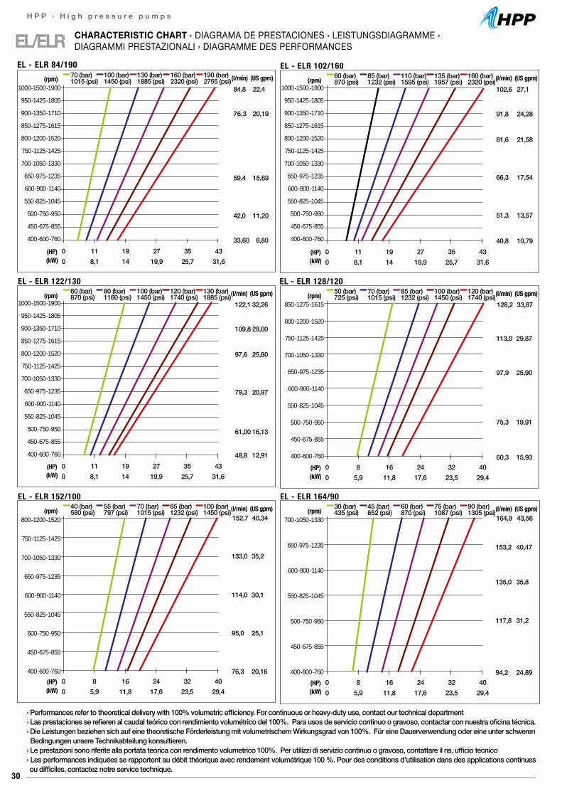
30
H P P › H i g h p r e s s u r e p u m p s
EL/ELR CHARACTERISTIC CHART › DIAGRAMA DE PRESTACIONES › LEISTUNGSDIAGRAMME ›DIAGRAMMI PRESTAZIONALI › DIAGRAMME DES PERFORMANCES
84,8
76,3
59,4
42,0
33,60
22,4
20,19
15,69
11,20
8,800 11 19 27 35 430 8,1 14 19,9 25,7 31,6
(HP)(kW)
70 (bar)1015 (psi)
100 (bar)1450 (psi)
130 (bar)1885 (psi)
160 (bar)2320 (psi)
190 (bar)2755 (psi)(l/min) (US gpm)
1000 -1500 -1900
950 -1425 -1805
900 -1350 -1710
850 -1275 -1615
800 -1200 -1520
750 -1125 -1425
700 -1050 -1330
650 -975 -1235
600 -900 -1140
550 -825 -1045
500 -750 -950
450 -675 -855
400 -600 -760
1000 -1500 -1900
950 -1425 -1805
900 -1350 -1710
850 -1275 -1615
800 -1200 -1520
750 -1125 -1425
700 -1050 -1330
650 -975 -1235
600 -900 -1140
550 -825 -1045
500 -750 -950
450 -675 -855
400 -600 -760
(rpm)
EL - ELR 84/190
102,6
91,8
81,6
66,3
51,3
40,8
27,1
24,28
21,58
17,54
13,57
10,790 11 19 27 35 430 8,1 14 19,9 25,7 31,6
(HP)(kW)
60 (bar)870 (psi)
85 (bar)1232 (psi)
110 (bar)1595 (psi)
135 (bar)1957 (psi)
160 (bar)2320 (psi)(l/min) (US gpm)(rpm)
EL - ELR 102/160
128,2 33,87
0 8 16 24 32 400 5,9 11,8 17,6 23,5 29,4
(HP)(kW)
50 (bar)725 (psi)
70 (bar)1015 (psi)
85 (bar)1232 (psi)
100 (bar)1450 (psi)
120 (bar)1740 (psi)(l/min) (US gpm)(rpm)
EL - ELR 128/120
113,0 29,87
97,9 25,90
75,3 19,91
60,3 15,93
122,1
109,8
97,6
79,3
61,00
48,8
32,26
29,00
25,80
20,97
16,13
12,910 11 19 27 35 430 8,1 14 19,9 25,7 31,6
(HP)(kW)
60 (bar)870 (psi)
80 (bar)1160 (psi)
100 (bar)1450 (psi)
120 (bar)1740 (psi)
130 (bar)1885 (psi)(l/min) (US gpm)(rpm)
EL - ELR 122/130
152,7 40,34
0 8 16 24 32 400 5,9 11,8 17,6 23,5 29,4
(HP)(kW)
40 (bar)580 (psi)
55 (bar)797 (psi)
70 (bar)1015 (psi)
85 (bar)1232 (psi)
100 (bar)1450 (psi)(l/min) (US gpm)(rpm)
EL - ELR 152/100
133,0 35,2
114,0 30,1
95,0 25,1
76,3 20,16
164,9 43,56
0 8 16 24 32 400 5,9 11,8 17,6 23,5 29,4
(HP)(kW)
30 (bar)435 (psi)
45 (bar)652 (psi)
60 (bar)870 (psi)
75 (bar)1087 (psi)
90 (bar)1305 (psi)(l/min) (US gpm)(rpm)
EL - ELR 164/90
153,2 40,47
135,0 35,8
117,8 31,2
94,2 24,89
1000 -1500 -1900
950 -1425 -1805
900 -1350 -1710
850 -1275 -1615
800 -1200 -1520
750 -1125 -1425
700 -1050 -1330
650 -975 -1235
600 -900 -1140
550 -825 -1045
500 -750 -950
450 -675 -855
400 -600 -760
850 -1275 -1615
800 -1200 -1520
750 -1125 -1425
700 -1050 -1330
650 -975 -1235
600 -900 -1140
550 -825 -1045
500 -750 -950
450 -675 -855
400 -600 -760
800 -1200 -1520
750 -1125 -1425
700 -1050 -1330
650 -975 -1235
600 -900 -1140
550 -825 -1045
500 -750 -950
450 -675 -855
400 -600 -760
700 -1050 -1330
650 -975 -1235
600 -900 -1140
550 -825 -1045
500 -750 -950
450 -675 -855
400 -600 -760
› Performances refer to theoretical delivery with 100% volumetric efficiency. For continuous or heavy-duty use, contact our technical department› Las prestaciones se refieren al caudal teórico con rendimiento volumétrico del 100%. Para usos de servicio continuo o gravoso, contactar con nuestra oficina técnica.› Die Leistungen beziehen sich auf eine theoretische Förderleistung mit volumetrischem Wirkungsgrad von 100%. Für eine Dauerverwendung oder eine unter schweren Bedingungen unsere Technikabteilung konsultieren.› Le prestazioni sono riferite alla portata teorica con rendimento volumetrico 100%. Per utilizzi di servizio continuo o gravoso, contattare il ns. ufficio tecnico› Les performances indiquées se rapportent au débit théorique avec rendement volumétrique 100 %. Pour des conditions d’utilisation dans des applications continues ou difficiles, contactez notre service technique.
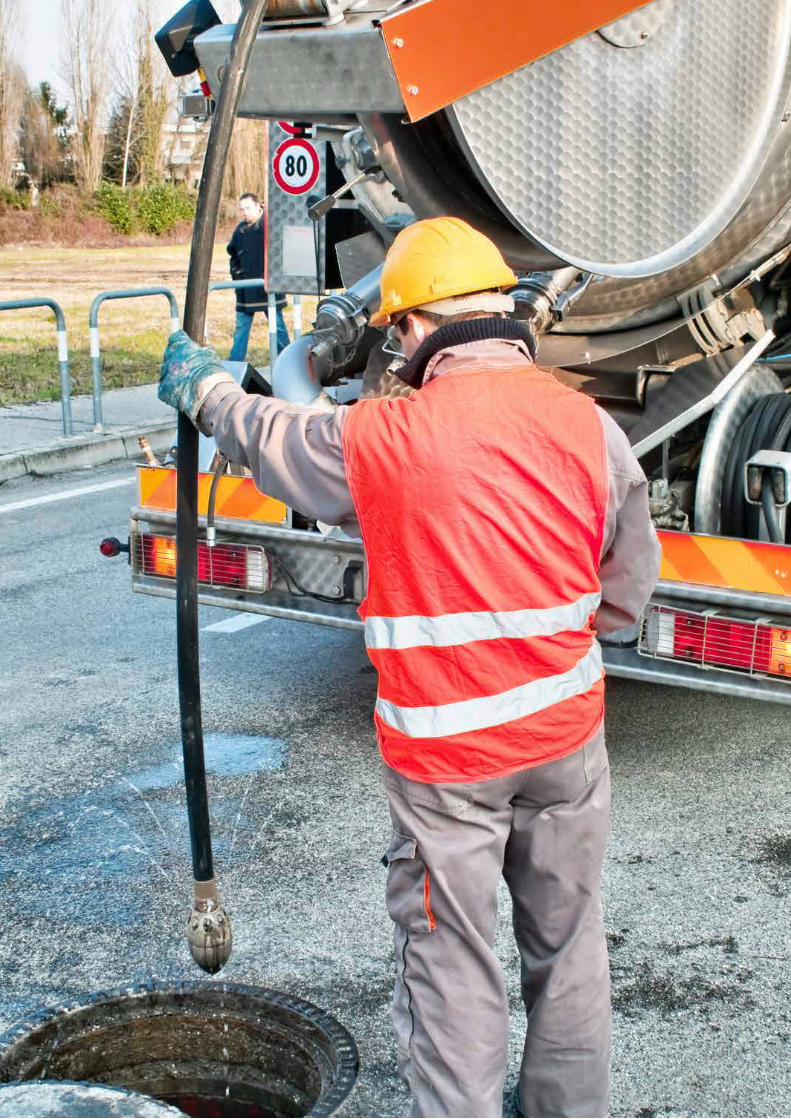
31
H P P › H i g h p r e s s u r e p u m p s
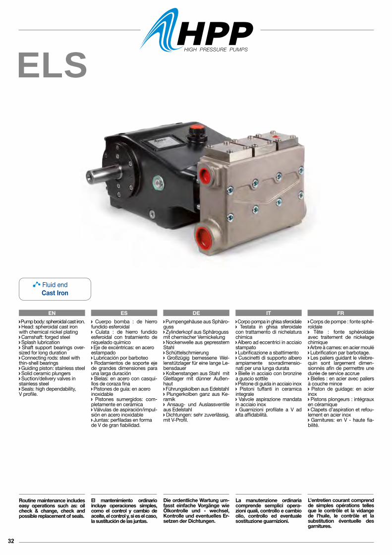
32
ELS
EN ES DE IT FR Corpo pompa in ghisa sferoidale Testata in ghisa sferoidale con trattamento di nichelatura chimica Albero ad eccentrici in acciaio stampato Lubrificazione a sbattimento Cuscinetti di supporto albero ampiamente sovradimensio-nati per una lunga durata Bielle in acciaio con bronzine a guscio sottile Pistone di guida in acciaio inox Pistoni tuffanti in ceramica integrale Valvole aspirazione mandata in acciaio inox Guarnizioni profilate a V ad alta affidabilità.
La manutenzione ordinaria comprende semplici opera-zioni quali, controllo e cambio olio, controllo ed eventuale sostituzione guarnizioni.
Pump body: spheroidal cast iron. Head: spheroidal cast ironwith chemical nickel plating Camshaft: forged steel Splash lubrication Shaft support bearings over-sized for long duration Connecting rods: steel withthin-shell bearings Guiding piston: stainless steel Solid ceramic plungers Suction/delivery valves instainless steel Seals: high dependability, V profile.
Routine maintenance includes easy operations such as: oil check & change, check and possible replacement of seals.
Cuerpo bomba : de hierro fundido esferoidal Culata : de hierro fundido esferoidal con tratamiento de niquelado químico Eje de excéntricas: en aceroestampado Lubricación por barboteo Rodamientos de soporte eje de grandes dimensiones para una larga duración Bielas: en acero con casqui-llos de coraza fina Pistones de guía: en aceroinoxidable Pistones sumergidos: com-pletamente en cerámica Válvulas de aspiración/impul-sión en acero inoxidable Juntas: perfiladas en forma de V de gran fiabilidad.
El mantenimiento ordinario incluye operaciones simples, como el control y cambio de aceite, el control y, si es el caso, la sustitución de las juntas.
Pumpengehäuse aus Sphäro-guss Zylinderkopf aus Sphärogussmit chemischer Vernickelung Nockenwelle aus gepresstem Stahl Schüttelschmierung Großzügig bemessene Wel-lenstützlager für eine lange Le-bensdauer Kolbenstangen aus Stahl mit Gleitlager mit dünner Außen-haut Führungskolben aus Edelstahl Plungerkolben ganz aus Ke-ramik Ansaug- und Auslassventile aus Edelstahl Dichtungen: sehr zuverlässig, mit V-Profil.
Die ordentliche Wartung um-fasst einfache Vorgänge wie Ölkontrolle und - wechsel, Kontrolle und eventuelles Er-setzen der Dichtungen.
Corps de pompe : fonte sphé-roïdale Tête : fonte sphéroïdale avec traitement de nickelage chimique Arbre à cames: en acier moulé Lubrification par barbotage. Les paliers guidant le vilebre-quin sont largement dimen-sionnés afin de permettre une durée de service accrue Bielles : en acier avec paliers à couche mince Piston de guidage: en acier inox Pistons plongeurs : intégraux en céramique Clapets d’aspiration et refou-lement en acier inox Garnitures: en V - haute fia-bilité.
L’entretien courant comprend de simples opérations telles que le contrôle et la vidange de l’huile, le contrôle et la substitution éventuelle des garnitures.
Fluid endCast Iron
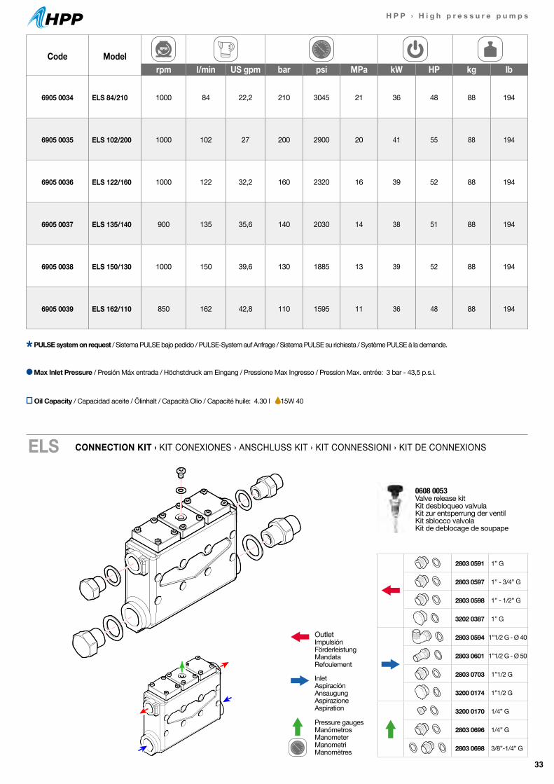
33
H P P › H i g h p r e s s u r e p u m p s
Code Modelrpm l/min US gpm bar psi MPa kW HP kg lb
6905 0034 ELS 84/210 1000 84 22,2 210 3045 21 36 48 88 194
6905 0035 ELS 102/200 1000 102 27 200 2900 20 41 55 88 194
6905 0036 ELS 122/160 1000 122 32,2 160 2320 16 39 52 88 194
6905 0037 ELS 135/140 900 135 35,6 140 2030 14 38 51 88 194
6905 0038 ELS 150/130 1000 150 39,6 130 1885 13 39 52 88 194
6905 0039 ELS 162/110 850 162 42,8 110 1595 11 36 48 88 194
CONNECTION KIT › KIT CONEXIONES › ANSCHLUSS KIT › KIT CONNESSIONI › KIT DE CONNEXIONSELS
0608 0053 Valve release kitKit desbloqueo valvulaKit zur entsperrung der ventilKit sblocco valvolaKit de deblocage de soupape
Max Inlet Pressure / Presión Máx entrada / Höchstdruck am Eingang / Pressione Max Ingresso / Pression Max. entrée: 3 bar - 43,5 p.s.i.
PULSE system on request / Sistema PULSE bajo pedido / PULSE-System auf Anfrage / Sistema PULSE su richiesta / Système PULSE à la demande.
OutletImpulsiónFörderleistungMandataRefoulement
InletAspiraciónAnsaugungAspirazioneAspiration
Pressure gaugesManómetrosManometerManometriManomètres
2803 0591 1” G
2803 0597 1” - 3/4” G
2803 0598 1” - 1/2” G
3202 0387 1” G
2803 0594 1”1/2 G - Ø 40
2803 0601 1”1/2 G - Ø 50
2803 0703 1”1/2 G
3200 0174 1”1/2 G
3200 0170 1/4” G
2803 0696 1/4” G
2803 0698 3/8”-1/4” G
Oil Capacity / Capacidad aceite / Ölinhalt / Capacità Olio / Capacité huile: 4.30 l 15W 40
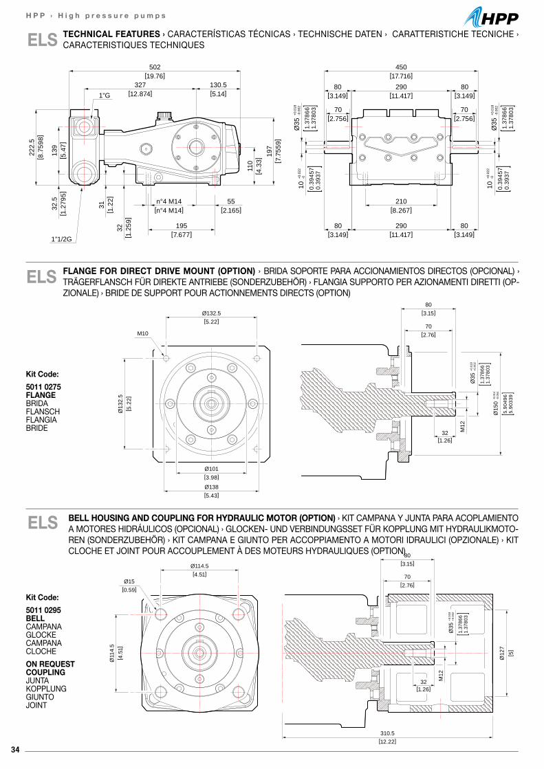
34
H P P › H i g h p r e s s u r e p u m p s
110
[ 4.3
3]
32[ 1
.259
]
31[ 1
.22]
139
[ 5.4
7]32
.5[ 1
.279
5]
222.
5[ 8
.759
8]
197
[ 7.7
559]
[12.874]327
[7.677]195
1”1/2G
1”G
[2.165]55
[n°4 M14]n°4 M14
[3.149]80
[3.149]80
[3.149]80
[2.756]70
[3.149]80
[2.756]70
[11.417]290
[11.417]290
[17.716]450
[8.267]210
10+0
.022
-0
0.39
457
0.39
371.
3786
61.
3780
3
Ø35
+0.0
18-0
.002
10+0
.022
-0
0.39
457
0.39
37
1.37
866
1.37
803
Ø35
+0.0
18-0
.002
[19.76]502
[5.14]130.5
ELS
80[3.15]Ø132.5
[5.22]
Ø101[3.98]
Ø138[5.43]
Ø13
2.5
[ 5.2
2]
70[2.76]
32[1.26]
M12
M10
Ø35
+0.0
18+0
.002
1.37
866
1.37
803
Ø15
0-0
.014
-0.0
54
5.90
496
5.90
339
ELS FLANGE FOR DIRECT DRIVE MOUNT (OPTION) › BRIDA SOPORTE PARA ACCIONAMIENTOS DIRECTOS (OPCIONAL) › TRÄGERFLANSCH FÜR DIREKTE ANTRIEBE (SONDERZUBEHÖR) › FLANGIA SUPPORTO PER AZIONAMENTI DIRETTI (OP-ZIONALE) › BRIDE DE SUPPORT POUR ACTIONNEMENTS DIRECTS (OPTION)
80[3.15]Ø114.5
[4.51]
Ø11
4.5
[ 4.5
1]
70[2.76]
32[1.26]
M12
Ø15
Ø35
+0.0
18+0
.002
1.37
866
1.37
803
[ 5]
Ø12
7
[0.59]
310.5 [12.22]
Kit Code:5011 0295 BELL CAMPANAGLOCKE CAMPANACLOCHEON REQUEST COUPLING JUNTAKOPPLUNG GIUNTOJOINT
Kit Code:5011 0275 FLANGE BRIDAFLANSCH FLANGIABRIDE
ELS
80[3.15]Ø132.5
[5.22]
Ø101[3.98]
Ø138[5.43]
Ø13
2.5
[ 5.2
2]
70[2.76]
32[1.26]
M12
M10
Ø35
+0.0
18+0
.002
1.37
866
1.37
803
Ø15
0-0
.014
-0.0
54
5.90
496
5.90
339
TECHNICAL FEATURES › CARACTERÍSTICAS TÉCNICAS › TECHNISCHE DATEN › CARATTERISTICHE TECNICHE ›CARACTERISTIQUES TECHNIQUES
BELL HOUSING AND COUPLING FOR HYDRAULIC MOTOR (OPTION) › KIT CAMPANA Y JUNTA PARA ACOPLAMIENTO A MOTORES HIDRÁULICOS (OPCIONAL) › GLOCKEN- UND VERBINDUNGSSET FÜR KOPPLUNG MIT HYDRAULIKMOTO-REN (SONDERZUBEHÖR) › KIT CAMPANA E GIUNTO PER ACCOPPIAMENTO A MOTORI IDRAULICI (OPZIONALE) › KIT CLOCHE ET JOINT POUR ACCOUPLEMENT À DES MOTEURS HYDRAULIQUES (OPTION)
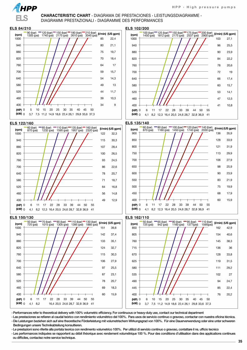
35
H P P › H i g h p r e s s u r e p u m p s
ELS 84/210
85
80
75
70
64
59
54
49
44
39
34
22,4
21,1
19,7
18,4
17
15,7
14,3
13
11,7
10,3
90 10 20 30 40 500 7,5 14,9 22,4 29,8 37,3
(HP)(kW)
90 (bar)1305 (psi)
120 (bar)1740 (psi)
150 (bar)2175 (psi)
180 (bar)2610 (psi)
210 (bar)3045 (psi) (l/min) (US gpm)
1000
940
880
820
760
700
640
580
520
460
400
(rpm)
53,7
1511,2
2518,6
3526,1
4533,6
ELS 102/200
103
96
90
84
78
72
66
60
53
47
41
27,1
25,5
23,9
22,2
20,6
19
17,4
15,7
14,1
12,5
10,80 11 22 33 44 550 8,2 16,4 24,6 32,8 41
(HP)(kW)
100 (bar)1450 (psi)
125 (bar)1812 (psi)
150 (bar)2175 (psi)
175 (bar)2537 (psi)
200 (bar)2900 (psi) (l/min) (US gpm)
1000
940
880
820
760
700
640
580
520
460
400
(rpm)
64,1
1712,3
2820,5
3928,7
5036,9
ELS 135/140
136
128
121
113
106
98
90
83
75
68
60
35,9
33,9
31,9
29,9
27,9
25,9
23,9
21,9
19,9
17,9
15,90 11 22 33 44 550 8,2 16,4 24,6 32,8 41
(HP)(kW)
60 (bar)870 (psi)
80 (bar)1160 (psi)
100 (bar)1450 (psi)
120 (bar)1740 (psi)
140 (bar)2030 (psi) (l/min) (US gpm)
900
850
800
750
700
650
600
550
500
450
400
(rpm)
64,1
1712,3
2820,5
3928,7
5036,9
ELS 122/160
122
115
107
100
93
86
78
71
64
56
49
32,3
30,3
28,4
26,5
24,5
22,6
20,7
18,7
16,8
14,8
12,90 11 22 33 44 550 8,2 16,4 24,6 32,8 41
(HP)(kW)
60 (bar)870 (psi)
85 (bar)1232 (psi)
110 (bar)1595 (psi)
135 (bar)1957 (psi)
160 (bar)2320 (psi) (l/min) (US gpm)
1000
940
880
820
760
700
640
580
520
460
400
(rpm)
64,1
1712,3
2820,5
3928,7
5036,9
ELS 150/130
151
142
133
124
115
106
97
87
78
69
60
39,8
37,4
35,1
32,7
30,3
27,9
25,5
23,1
20,7
18,3
15,90 11 22 33 44 550 8,2 16,4 24,6 32,8 41
(HP)(kW)
50 (bar)725 (psi)
70 (bar)1015 (psi)
90 (bar)1305 (psi)
110 (bar)1395 (psi)
130 (bar)1885 (psi) (l/min) (US gpm)
1000
940
880
820
760
700
640
580
520
460
400
(rpm)
64,1
17 2820,5
3928,7
5036,9
ELS 162/110
162
154
145
136
128
119
111
102
94
85
76
42,9
40,6
38,3
36
33,8
31,5
29,2
27
24,7
22,4
20,20 10 20 30 40 500 7,5 14,9 22,4 29,8 37,3
(HP)(kW)
50 (bar)725 (psi)
65 (bar)942 (psi)
80 (bar)1160 (psi)
95 (bar)1377(psi)
110 (bar)1595(psi) (l/min) (US gpm)
850
805
760
715
670
625
580
535
490
445
400
(rpm)
63,7
1511,2
2518,6
3526,1
4533,6
ELS CHARACTERISTIC CHART › DIAGRAMA DE PRESTACIONES › LEISTUNGSDIAGRAMME ›DIAGRAMMI PRESTAZIONALI › DIAGRAMME DES PERFORMANCES
› Performances refer to theoretical delivery with 100% volumetric efficiency. For continuous or heavy-duty use, contact our technical department› Las prestaciones se refieren al caudal teórico con rendimiento volumétrico del 100%. Para usos de servicio continuo o gravoso, contactar con nuestra oficina técnica.› Die Leistungen beziehen sich auf eine theoretische Förderleistung mit volumetrischem Wirkungsgrad von 100%. Für eine Dauerverwendung oder eine unter schweren Bedingungen unsere Technikabteilung konsultieren.› Le prestazioni sono riferite alla portata teorica con rendimento volumetrico 100%. Per utilizzi di servizio continuo o gravoso, contattare il ns. ufficio tecnico› Les performances indiquées se rapportent au débit théorique avec rendement volumétrique 100 %. Pour des conditions d’utilisation dans des applications continues ou difficiles, contactez notre service technique.
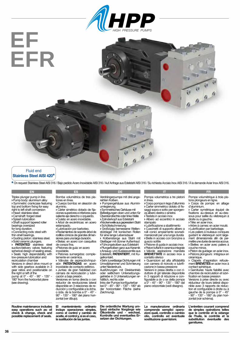
36
EFEFR
Pompa volumetrica a tre pistoni in linea.› Corpo pompa in lega d’alluminio› Carter simmetrico dotato di fis-saggi sopra e sotto per sporgen-za albero destra o sinistra› Testata in acciaio inox› Albero ad eccentrici in acciaio stampato› Lubrificazione a sbattimento› Cuscinetti di supporto albero a rulli conici ampiamente sovradi-mensionati per una lunga durata› Bielle in acciaio con bronzine a guscio sottile› Pistone di guida in acciaio inox› Pistoni tuffanti in ceramica integrale› Valvole aspirazione mandata BREVETTATE in acciaio inox a contatto sferico› Guarnizioni ad alta affidabilità con camera di ricircolo e lubrifi-cazione in bassa pressioneVersioni in presa diretta o con ri-duttore di giri laterale disponibile in 3 rapporti di riduzione e con-figurabile a dx o sx della pompa a 0° - 45° - 90° - 135° - 180° dal piano orizzontale (vedi disegno).
La manutenzione ordinaria comprende semplici opera-zioni quali, controllo e cambio olio, controllo ed eventuale sostituzione guarnizioni.
Pompe volumétrique à trois pis-tons plongeurs en ligne.› Corps de pompe: en alliage d’aluminium.› Carter symétrique équipé de fixations au-dessus et au-des-sous pour saillie du vilebrequin à droite ou à gauche.› Tête: en acier inox.› Arbre à cames: en acier moulé.› Lubrification par barbotage.› Les paliers à rouleaux coniques guidant le vilebrequin sont large-ment dimensionnés afin de per-mettre une durée de service accrue.› Bielles: en acier avec paliers à couche mince.› Piston de guidage: en acier inox.› Pistons plongeurs : intégraux en céramique.› Clapets d’aspiration refoule-ment BREVETÉS en acier inox à contact sphérique.› Garnitures: haute fiabilité avec chambre de recirculation et lubri-fication en basse pressionVersions à prise directe ou avec réducteur de tours latéral dispo-nible avec 3 rapports de réduc-tion et configurable à droite ou à gauche de la pompe à 0° - 45° - 90° - 135° - 180° du plan hori-zontal (voir schéma).
L’entretien courant comprend de simples opérations telles que le contrôle et la vidange de l’huile, le contrôle et la substitution éventuelle des garnitures.
Verdrängerpumpe mit drei ange-reihten Kolben.› Pumpengehäuse aus Alumini-umlegierung.› Symmetrisches Gehäuse mit Befestigungen oben und unten für Überstandrechte oder linke Welle › Zylinderkopf aus Edelstahl› Nockenwelle aus gepresstem Stahl› Schüttelschmierung› Großzügig bemessene Wellen-stützlager mit konischen Rollen für eine lange Lebensdauer› Kolbenstange aus Stahl mit Gleitlager mit dünner Außenhaut › Führungskolben aus Edelstahl› Plungerkolben ganz aus Keramik› Ansaug- und Auslassventile aus Edelstahl, PATENTIERT, mit Ku-gelkontakt.› Sehr zuverlässige Dichtungen mit Umwälzkammer und Schmierung unter Niederdruck.Ausführungen mit Direktantrieb oder seitlichem Untersetzungs-getriebe in 3 Untersetzungen er-hältlich, rechts oderlinks der Pumpe konfigurierbar bei 0° - 45° - 90° - 135° - 180° abder horizontalen Fläche (siehe Zeichnung).
Die ordentliche Wartung um-fasst einfache Vorgänge wie Ölkontrolle und - wechsel, Kontrolle und eventuelles Er-setzen der Dichtungen.
Bomba volumétrica de tres pis-tones en línea.› Cuerpo bomba: en aleación de aluminio.› Cárter simétrico dotado de fija-ciones superiores e inferiores para saliente eje derecho o izquierdo.› Culata: en acero inoxidable.› Árbol de excéntricas: en acero estampado.› Lubricación por barboteo.› Rodamientos de soporte árbol de rodillos cónicos de grandes dimen-siones para una larga duración.› Bielas: en acero con casquillos de coraza fina.› Pistones de guía: en aceroinoxidable.› Pistones sumergidos: comple-tamente en cerámica.› Válvulas de aspiración/impul-sión PATENTADAS en acero inoxidable de contacto esférico.› Juntas: de gran fiabilidad con cámara de recirculación y lubri-cación a baja presión.Versiones en toma directa o con reductor de revoluciones lateral disponible en 3 relaciones de re-ducción y configurable a la dcha. o izda. de la bomba a 0° - 45° - 90° - 135° - 180° del plano hori-zontal (ver dibujo).
El mantenimiento ordinario incluye operaciones simples, como el control y cambio de aceite, el control y, si es el caso, la sustitución de las juntas.
Triplex plunger pump in line.› Pump body: aluminium alloy › Symmetric crankcase featuring top and bottom fixing for easy right to left shaft conversion› Head: stainless steel.› Camshaft: forged steel› Splash lubrication› Shaft support tapered roller bearings oversizedfor long duration.› Connecting rods: steel with thin-shell bearings.› Guiding piston: stainless steel.› Solid ceramic plungers. › PATENTED stainless steel suction/delivery valves featuring spherical design of sealing areas.› Seals: high dependability with low-pressure lubrication and recirculation chamber Versions in direct drive mount or with side gearbox available in 3 gear ratios and positionable on the right or left of the pump at 0° - 45° - 90° - 135° - 180° from the horizontal plane (see drawing).
Routine maintenance includes easy operations such as: oil check & change, check and possible replacement of seals.
EN ES DE IT FR
Fluid endStainless Steel AISI 420 On request Stainless Steel AISI 316 / Bajo pedido Acero Inoxidable AISI 316 / Auf Anfrage aus Edelstahl AISI 316 / Su richiesta Acciaio Inox AISI 316 / À la demande Acier Inox AISI 316.

37
H P P › H i g h p r e s s u r e p u m p s
CONNECTION KIT › KIT CONEXIONES › ANSCHLUSS KIT › KIT CONNESSIONI › KIT DE CONNEXIONSEF / EFR
Available in hot-waterversion max 85°CDisponible en versión paraagua caliente máx. 85°CErhältlich in der Ausführung für max. 85° C warmes WasserDisponibile in versione per acqua calda max 85°CDisponible en version pour eau chaude max. 85°C
Available with AISI 316 head and components in contact with waterDisponible con cabeza y componentesa contacto con el agua en AISI 316Erhältlich mit Kopfteil und Bestandteilen in Berührung mit Wasser in AISI 316Disponibile con testata e componenti a contatto con l’acqua in AISI 316Disponible avec tête et composants au contact de l’eau en AISI 316
Code Modelrpm l/min US gpm bar psi MPa kW HP kg lb
6919 0025 EF 75/280 850 75 19,8 280 4060 28 41 56 90 1986919 0006 EF 88/250 1000 88 23 250 3625 25 43 59 90 1986919 0020 EFR 88/250 1500 88 23 250 3625 25 43 59 105 2316919 0021 EFR 88/250 1800 88 23 250 3625 25 43 59 105 2316919 0022 EFR 88/250 2200 88 23 250 3625 25 43 59 105 2316919 0002 EF 111/210 1000 111 29 210 3045 21 46 62 90 1986919 0014 EFR 111/210 1500 111 29 210 3045 21 46 62 105 2316919 0015 EFR 111/210 1800 111 29 210 3045 21 46 62 105 2316919 0016 EFR 111/210 2200 111 29 210 3045 21 46 62 105 2316919 0007 EF 123/150 800 123 33 150 2175 15 36 49 90 1986919 0023 EFR 123/150 1500 123 33 150 2175 15 36 49 105 2316919 0024 EFR 123/150 1800 123 33 150 2175 15 36 49 105 2316919 0010 EF 127/180 1000 127 34 180 2610 18 45 61 90 1986919 0032 EFR 127/180 1500 127 34 180 2610 18 45 61 105 2316919 0033 EFR 127/180 1800 127 34 180 2610 18 45 61 105 2316919 0034 EFR 127/180 2200 127 34 180 2610 18 45 61 105 2316919 0008 EF 139/150 900 139 37 150 2175 15 41 55 90 1986919 0003 EF 154/150 1000 154 41 150 2175 15 45 62 90 1986919 0017 EFR 154/150 1500 154 41 150 2175 15 45 62 105 2316919 0018 EFR 154/150 1800 154 41 150 2175 15 45 62 105 2316919 0019 EFR 154/150 2200 154 41 150 2175 15 45 62 105 2316919 0009 EF 165/120 900 165 44 120 1740 12 39 53 90 1986919 0001 EF 183/120 1000 183 48 120 1740 12 43 59 90 1986919 0011 EFR 183/120 1500 183 48 120 1740 12 43 59 105 2316919 0012 EFR 183/120 1800 183 48 120 1740 12 43 59 105 2316919 0013 EFR 183/120 2200 183 48 120 1740 12 43 59 105 231
Max Inlet Pressure / Presión Máx entrada / Höchstdruck am Eingang / Pressione Max Ingresso / Pression Max. entrée: 3 bar - 43,5 p.s.i.
Flushing systems available on request on selected versions. / Versiones disponibles bajo pedido con sistema de enjuague (flushing) juntas estancas. / Spülsystem der Dichtungen erhältlich auf Anfrage auf ausgewählte Pumpenversionen. / Versioni disponibili su richiesta con sistema di flussaggio tenute. / Versions disponibles sur demande avec système de rinçage par flushing des joints d’étanchéité.
OutletImpulsiónFörderleistungMandataRefoulement
InletAspiraciónAnsaugungAspirazioneAspiration
Pressure gaugesManómetrosManometerManometriManomètres
2803 0591 1” G
2803 0597 1” - 3/4” G
2803 0598 1” - 1/2” G
3202 0387 1” G
2803 0594 1”1/2 G - Ø 40
2803 0601 1”1/2 G - Ø 50
2803 0703 1”1/2 G
3200 0174 1”1/2 G
2803 0599 2” G - Ø 50
2803 0592 2” G - Ø 50
2803 0704 2” G
3200 0175 2” G
3200 0212 1/2” G
2803 0699 1/2” G
2803 0700 1/2” - 3/8” G
Oil Capacity / Capacidad aceite / Ölinhalt / Capacità Olio / Capacité huile: 4.43 l 80W 90Oil Capacity with Gearbox / Capacidad aceite con Reductor / Ölinhalt mit Untersetzungsgetriebe / Capacità Olio con Riduttore / Capacité huile avec Réducteur: 5.88 l 80W 90
PULSE system on request / Sistema PULSE bajo pedido / PULSE-System auf Anfrage / Sistema PULSE su richiesta / Système PULSE à la demande.
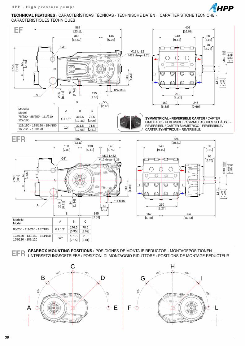
38
H P P › H i g h p r e s s u r e p u m p s
587[23.11]
180[7.09]
138[5.43]
146[5.75]
65[ 2
.56]
[7.68]B 195
55[2.17]
110
20.5
[ 0.8
1]
526[20.71]
240[9.45]
80[3.15]
70[2.76]
210[8.27]
364[14.33]
162[6.38]
[ 4.3
3]
A
G1"M12 L=32
M12 deep=1.26
Ø40
+0.0
15+0
.002
1.57
541.
5749
12-0 -0
.052
0.47
20.
470
34[ 1
.34] n°4 M16
ModelloModel A
G1 1/2"
G2"
176.5 78.5
B C
88/250 - 111/210 - 127/180
181.5 71.5123/150 - 139/150 - 154/150165/120 - 183/120
[6.95] [3.09]
[7.15] [2.81]
C
276.
5[ 1
0.9]
587[23.11]318
[12.52]146
[5.75]
276.
5[ 1
0.9] 65
[ 2.5
6]
34[ 1
.34]
195[7.68]
A
B
C
G1"M12 L=32
M12 deep=1.26
55[2.17]
n°4 M16
20.5
[ 0.8
1]
408[16.06]
240[9.45]
80[3.15]
70[2.76]
210[8.27]
246[9.69]
162[6.38]
110
[ 4.3
3]
12-0 -0
.052
0.47
20.
470
Ø40
+0.0
15+0
.002
1.57
541.
5749
ModelloModel A
G1 1/2"
G2"
316.5 78.5
B C
75/280 - 88/250 - 111/210127/180
321.5 71.5123/150 - 139/150 - 154/150165/120 - 183/120
[12.46] [3.09]
[12.66] [2.81]
GEARBOX MOUNTING POSITIONS › POSICIONES DE MONTAJE REDUCTOR › MONTAGEPOSITIONEN UNTERSETZUNGSGETRIEBE › POSIZIONI DI MONTAGGIO RIDUTTORE › POSITIONS DE MONTAGE RÉDUCTEUR
EF
EFR
SYMMETRICAL - REVERSIBLE CARTER / CÁRTER SIMÉTRICO - REVERSIBLE / SYMMETRISCHES GEHÄUSE - REVERSIBEL / CARTER SIMMETRICO - REVERSIBILE / CARTER SYMÉTRIQUE – RÉVERSIBLE.
45° 45°
45° 45°
45° 45°
45° 45°
A
B
C
D
E L
I
H
G
F
EFR
TECHNICAL FEATURES › CARACTERÍSTICAS TÉCNICAS › TECHNISCHE DATEN › CARATTERISTICHE TECNICHE ›CARACTERISTIQUES TECHNIQUES
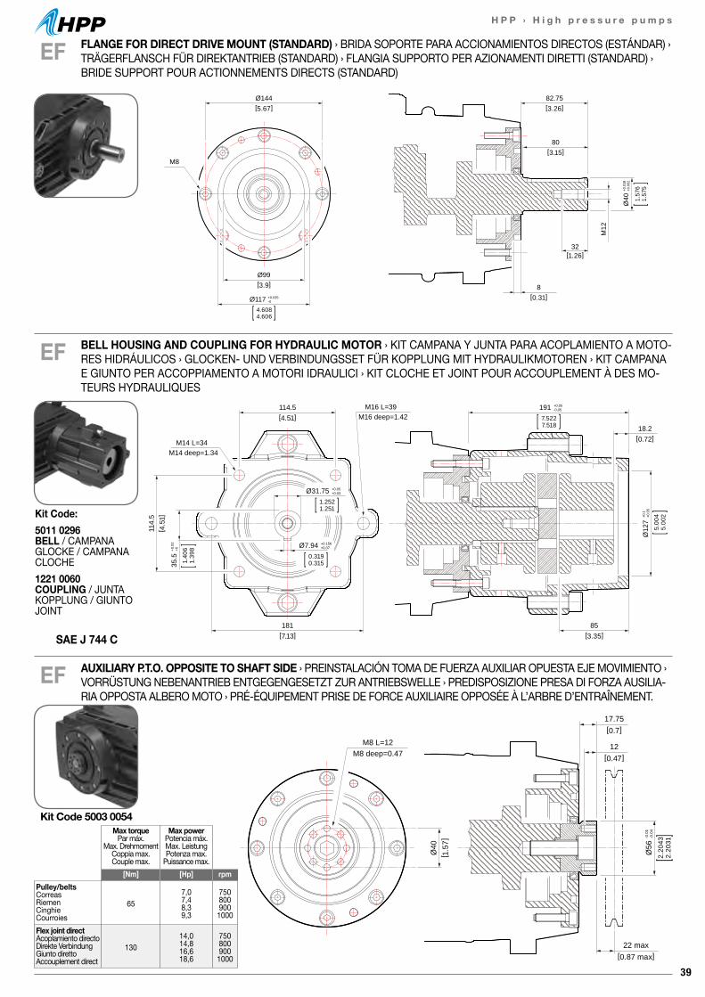
39
H P P › H i g h p r e s s u r e p u m p s
17.75[0.7]
22 max[0.87 max]
12[0.47]
Ø56
-0.0
1-0
.04
2.20
432.
2031
Ø40
[ 1.5
7]
M8 L=12M8 deep=0.47
17.75[0.7]
22 max[0.87 max]
12[0.47]
Ø56
-0.0
1-0
.04
2.20
432.
2031
Ø40
[ 1.5
7]
M8 L=12M8 deep=0.47
EF
EF
82.75[3.26]
Ø144[5.67]
Ø99[3.9]
80[3.15]
32[1.26]
8[0.31]
M12
M8
Ø117 +0.035-0
4.6084.606
Ø40
+0.0
18+0
.002
1.57
61.
575
FLANGE FOR DIRECT DRIVE MOUNT (STANDARD) › BRIDA SOPORTE PARA ACCIONAMIENTOS DIRECTOS (ESTÁNDAR) › TRÄGERFLANSCH FÜR DIREKTANTRIEB (STANDARD) › FLANGIA SUPPORTO PER AZIONAMENTI DIRETTI (STANDARD) › BRIDE SUPPORT POUR ACTIONNEMENTS DIRECTS (STANDARD)
BELL HOUSING AND COUPLING FOR HYDRAULIC MOTOR › KIT CAMPANA Y JUNTA PARA ACOPLAMIENTO A MOTO-RES HIDRÁULICOS › GLOCKEN- UND VERBINDUNGSSET FÜR KOPPLUNG MIT HYDRAULIKMOTOREN › KIT CAMPANA E GIUNTO PER ACCOPPIAMENTO A MOTORI IDRAULICI › KIT CLOCHE ET JOINT POUR ACCOUPLEMENT À DES MO-TEURS HYDRAULIQUES
114.5[4.51]
18.2[0.72]
114.
5[ 4
.51]
181[7.13]
85[3.35]
M14 L=34M14 deep=1.34
M16 L=39M16 deep=1.42
191 +0.05-0.05
7.5227.518
Ø31.75 +0.05+0.03
1.2521.251
Ø7.94 +0.156+0.07
0.3190.315
Ø12
7+0
.1+0
.05
5.00
45.
002
35.5
+0.0
2+0
1.40
61.
398
EF AUXILIARY P.T.O. OPPOSITE TO SHAFT SIDE › PREINSTALACIÓN TOMA DE FUERZA AUXILIAR OPUESTA EJE MOVIMIENTO › VORRÜSTUNG NEBENANTRIEB ENTGEGENGESETZT ZUR ANTRIEBSWELLE › PREDISPOSIZIONE PRESA DI FORZA AUSILIA-RIA OPPOSTA ALBERO MOTO › PRÉ-ÉQUIPEMENT PRISE DE FORCE AUXILIAIRE OPPOSÉE À L’ARBRE D’ENTRAÎNEMENT.
Max torquePar máx.
Max. DrehmomentCoppia max.Couple max.
Max powerPotencia máx.Max. LeistungPotenza max.
Puissance max.[Nm] [Hp] rpm
Pulley/beltsCorreasRiemenCinghieCourroies
657,07,48,39,3
7508009001000
Flex joint directAcoplamiento directoDirekte VerbindungGiunto direttoAccouplement direct
13014,014,816,618,6
7508009001000
Kit Code 5003 0054
SAE J 744 C
Kit Code:5011 0296 BELL / CAMPANAGLOCKE / CAMPANACLOCHE1221 0060 COUPLING / JUNTAKOPPLUNG / GIUNTOJOINT
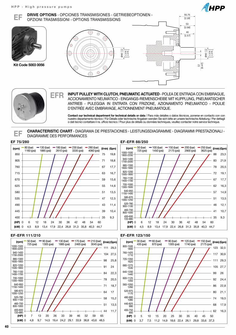
40
H P P › H i g h p r e s s u r e p u m p s
DRIVE OPTIONS › OPCIONES TRANSMISIONES › GETRIEBEOPTIONEN › OPZIONI TRASMISSIONI › OPTIONS TRANSMISSIONSEF
CHARACTERISTIC CHART › DIAGRAMA DE PRESTACIONES › LEISTUNGSDIAGRAMME › DIAGRAMMI PRESTAZIONALI › DIAGRAMME DES PERFORMANCESEF
EFR
EF-EFR 88/250(rpm)
1000-15001800-2200940-1400
1700-2000880-1300
1600-1900820-1200
1500-1800760-1100
1400-1700700-1000
1300-1600640-950
1150-1400580-870
1000-1250520-780
900-1100460-700
800-1000400-600720-880
(l/min)
88
83
78
72
67
62
57
51
46
41
35
(Gpm)
23,3
21,9
20,5
19,1
17,7
16,3
14,9
13,5
12,1
10,7
9,3
50 (bar) 100 (bar) 150 (bar) 200 (bar) 250 (bar)725 (psi) 1450 (psi) 2175 (psi) 2900 (psi) 3625 (psi)
(HP) 0 6 12 18 24 30 36 42 48 54 60(kW) 0 4,5 8,9 13,4 17,9 22,4 26,8 31,3 35,8 40,3 44,7
EF-EFR 123/150(l/min)
123
117
111
105
99
92
86
80
74
68
62
(Gpm)
32,5
30,9
29,3
27,7
26
24,4
22,8
21,1
19,5
17,9
16,3
30 (bar) 60 (bar) 90 (bar) 120 (bar) 150 (bar)435 (psi) 870 (psi) 1305 (psi) 1740 (psi) 2175 (psi)
(HP) 0 5 10 15 20 25 30 35 40 45 50(kW) 0 3,7 7,5 11,2 14,9 18,6 22,4 26,1 29,8 33,6 37,3
EF-EFR 111/210(rpm)
1000-15001800-2200940-1400
1700-2000880-1300
1600-1900820-1200
1500-1800760-1100
1400-1700700-1000
1300-1600640-950
1150-1400580-870
1000-1250520-780
900-1100460-700
800-1000400-600720-880
(l/min)
111
104
98
91
84
78
71
64
58
51
44
(Gpm)
29,3
27,5
25,8
24
22,3
20,5
18,7
17
15,2
13,5
11,7
50 (bar) 90 (bar) 130 (bar) 170 (bar) 210 (bar)725 (psi) 1305 (psi) 1885 (psi) 2465 (psi) 3045 (psi)
(HP) 0 7 13 20 26 33 39 46 52 59 65(kW) 0 4,8 9,7 14,5 19,4 24,2 29,1 33,9 38,8 43,6 48,5
55.75[2.19]
12[ 0
.47]
53[2.08]
40[1.57]
Ø40
+0.0
18+0
.002
1.57
61.
575
Ø40
+0.0
18+0
.002
1.57
61.
575
Kit Code 5003 0056
(rpm)800-1500
1800760-1425
1710720-1350
1620680-1275
1530640-1200
1440600-1125
1350560-1050
1260520-975
1170480-900
1080440-825
990400-750
900
EF 75/280(rpm)
850
805
760
715
670
625
580
535
490
445
400
(l/min)
75
71
67
63
59
55
51
47
43
39
35
(Gpm)
19,8
18,8
17,7
16,7
15,6
14,6
13,5
12,5
11,4
10,4
9,3
80 (bar) 130 (bar) 180 (bar) 230 (bar) 280 (bar)1160 (psi) 1885 (psi) 2610 (psi) 3335 (psi) 4060 (psi)
(HP) 0 6 12 18 24 30 36 42 48 54 60(kW) 0 4,5 8,9 13,4 17,9 22,4 26,8 31,3 35,8 40,3 44,7
INPUT PULLEY WITH CLUTCH, PNEUMATIC ACTUATED › POLEA DE ENTRADA CON EMBRAGUE, ACCIONAMIENTO NEUMÁTICO › EINGANGS-RIEMENSCHEIBE MIT KUPPLUNG, PNEUMATISCHER ANTRIEB › PULEGGIA IN ENTRATA CON FRIZIONE, AZIONAMENTO PNEUMATICO › POULIE D'ENTRÉE AVEC EMBRAYAGE, ACTIONNEMENT PNEUMATIQUE.Contact our technical department for technical details or data / Para más detalles o datos técnicos, ponerse en contacto con con nuestro departamento técnico / Für Details oder technische Angaben wenden Sie sich bitte an unsere technische Abteilung / Per dettagli o dati tecnici contattare il ns. ufficio tecnico / Pour plus de détails ou données techniques, veuillez contacter notre service technique.
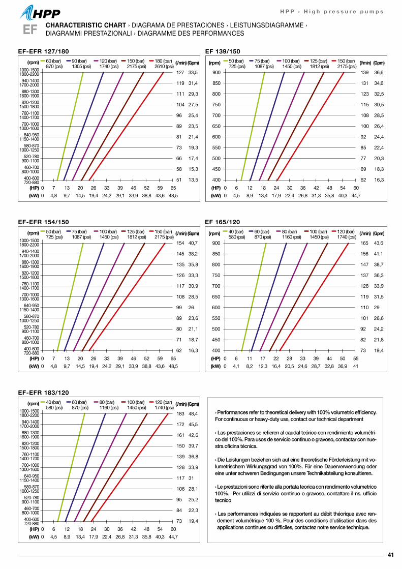
41
H P P › H i g h p r e s s u r e p u m p s
EF-EFR 127/180(rpm)
1000-15001800-2200940-1400
1700-2000880-1300
1600-1900820-1200
1500-1800760-1100
1400-1700700-1000
1300-1600640-950
1150-1400580-870
1000-1250520-780
900-1100460-700
800-1000400-600720-880
(l/min)
127
119
111
104
96
89
81
73
66
58
51
(Gpm)
33,5
31,4
29,3
27,5
25,4
23,5
21,4
19,3
17,4
15,3
13,5
60 (bar) 90 (bar) 120 (bar) 150 (bar) 180 (bar)870 (psi) 1305 (psi) 1740 (psi) 2175 (psi) 2610 (psi)
(HP) 0 7 13 20 26 33 39 46 52 59 65(kW) 0 4,8 9,7 14,5 19,4 24,2 29,1 33,9 38,8 43,6 48,5
CHARACTERISTIC CHART › DIAGRAMA DE PRESTACIONES › LEISTUNGSDIAGRAMME ›DIAGRAMMI PRESTAZIONALI › DIAGRAMME DES PERFORMANCESEF
EF 165/120(rpm)
900
850
800
750
700
650
600
550
500
450
400
(l/min)
165
156
147
137
128
119
110
101
92
82
73
(Gpm)
43,6
41,1
38,7
36,3
33,9
31,5
29
26,6
24,2
21,8
19,4
40 (bar) 60 (bar) 80 (bar) 100 (bar) 120 (bar)580 (psi) 870 (psi) 1160 (psi) 1450 (psi) 1740 (psi)
(HP) 0 6 11 17 22 28 33 39 44 50 55(kW) 0 4,1 8,2 12,3 16,4 20,5 24,6 28,7 32,8 36,9 41
EF-EFR 183/120(l/min)
183
172
161
150
139
128
117
106
95
84
73
(Gpm)
48,4
45,5
42,6
39,7
36,8
33,9
31
28,1
25,2
22,3
19,4
40 (bar) 60 (bar) 80 (bar) 100 (bar) 120 (bar)580 (psi) 870 (psi) 1160 (psi) 1450 (psi) 1740 (psi)
(HP) 0 6 12 18 24 30 36 42 48 54 60(kW) 0 4,5 8,9 13,4 17,9 22,4 26,8 31,3 35,8 40,3 44,7
(rpm)1000-15001800-2200940-1400
1700-2000880-1300
1600-1900820-1200
1500-1800760-1100
1400-1700700-1000
1300-1600640-950
1150-1400580-870
1000-1250520-780
900-1100460-700
800-1000400-600720-880
EF 139/150(rpm)
900
850
800
750
700
650
600
550
500
450
400
(l/min)
139
131
123
115
108
100
92
85
77
69
62
(Gpm)
36,6
34,6
32,5
30,5
28,5
26,4
24,4
22,4
20,3
18,3
16,3
50 (bar) 75 (bar) 100 (bar) 125 (bar) 150 (bar)725 (psi) 1087 (psi) 1450 (psi) 1812 (psi) 2175 (psi)
(HP) 0 6 12 18 24 30 36 42 48 54 60(kW) 0 4,5 8,9 13,4 17,9 22,4 26,8 31,3 35,8 40,3 44,7
EF-EFR 154/150(rpm)
1000-15001800-2200940-1400
1700-2000880-1300
1600-1900820-1200
1500-1800760-1100
1400-1700700-1000
1300-1600640-950
1150-1400580-870
1000-1250520-780
900-1100460-700
800-1000400-600720-880
(l/min)
154
145
135
126
117
108
99
89
80
71
62
(Gpm)
40,7
38,2
35,8
33,3
30,9
28,5
26
23,6
21,1
18,7
16,3
50 (bar) 75 (bar) 100 (bar) 125 (bar) 150 (bar)725 (psi) 1087 (psi) 1450 (psi) 1812 (psi) 2175 (psi)
(HP) 0 7 13 20 26 33 39 46 52 59 65(kW) 0 4,8 9,7 14,5 19,4 24,2 29,1 33,9 38,8 43,6 48,5
› Performances refer to theoretical delivery with 100% volumetric efficiency. For continuous or heavy-duty use, contact our technical department
› Las prestaciones se refieren al caudal teórico con rendimiento volumétri-co del 100%. Para usos de servicio continuo o gravoso, contactar con nue-stra oficina técnica.
› Die Leistungen beziehen sich auf eine theoretische Förderleistung mit vo-lumetrischem Wirkungsgrad von 100%. Für eine Dauerverwendung oder eine unter schweren Bedingungen unsere Technikabteilung konsultieren.
› Le prestazioni sono riferite alla portata teorica con rendimento volumetrico 100%. Per utilizzi di servizio continuo o gravoso, contattare il ns. ufficio tecnico
› Les performances indiquées se rapportent au débit théorique avec ren-dement volumétrique 100 %. Pour des conditions d’utilisation dans des applications continues ou difficiles, contactez notre service technique.
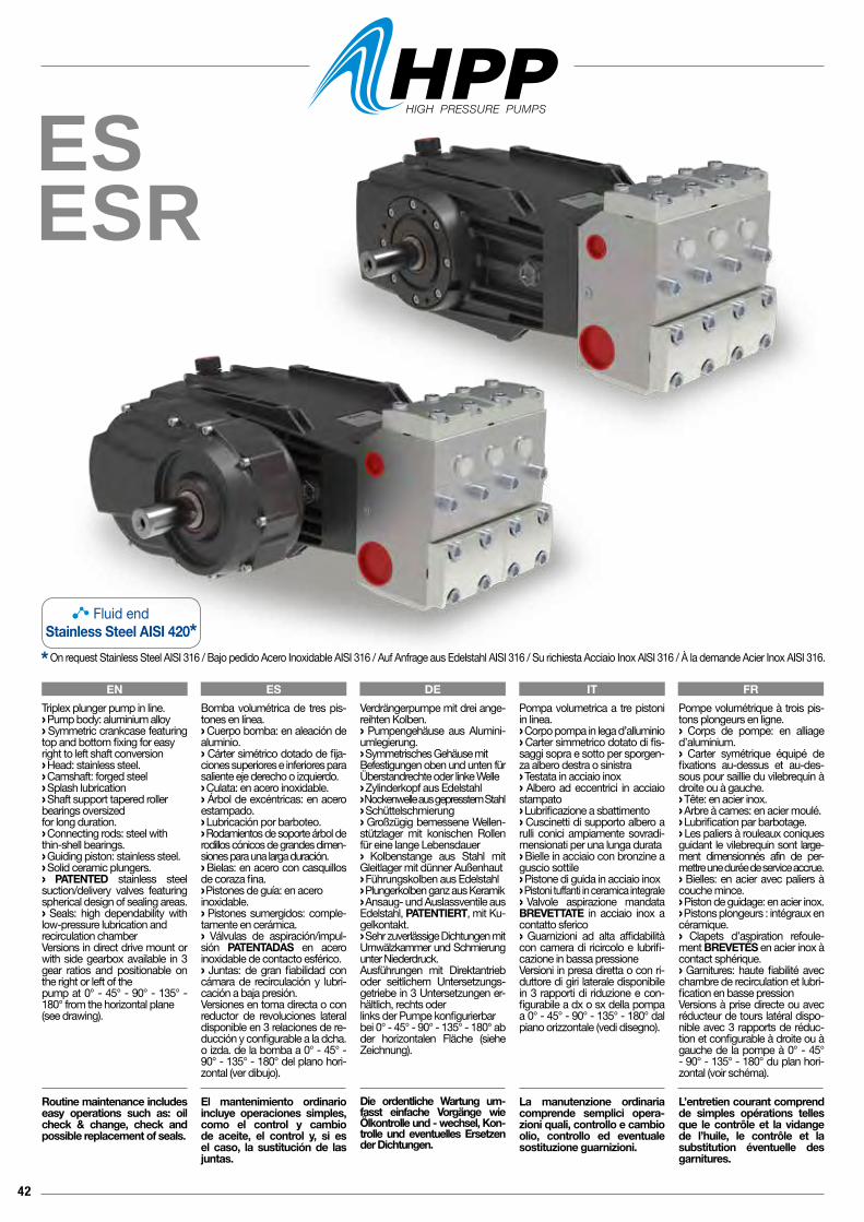
42
ESESR
Pompa volumetrica a tre pistoni in linea.› Corpo pompa in lega d’alluminio› Carter simmetrico dotato di fis-saggi sopra e sotto per sporgen-za albero destra o sinistra› Testata in acciaio inox› Albero ad eccentrici in acciaio stampato› Lubrificazione a sbattimento› Cuscinetti di supporto albero a rulli conici ampiamente sovradi-mensionati per una lunga durata› Bielle in acciaio con bronzine a guscio sottile› Pistone di guida in acciaio inox› Pistoni tuffanti in ceramica integrale› Valvole aspirazione mandata BREVETTATE in acciaio inox a contatto sferico› Guarnizioni ad alta affidabilità con camera di ricircolo e lubrifi-cazione in bassa pressioneVersioni in presa diretta o con ri-duttore di giri laterale disponibile in 3 rapporti di riduzione e con-figurabile a dx o sx della pompa a 0° - 45° - 90° - 135° - 180° dal piano orizzontale (vedi disegno).
La manutenzione ordinaria comprende semplici opera-zioni quali, controllo e cambio olio, controllo ed eventuale sostituzione guarnizioni.
Pompe volumétrique à trois pis-tons plongeurs en ligne.› Corps de pompe: en alliage d’aluminium.› Carter symétrique équipé de fixations au-dessus et au-des-sous pour saillie du vilebrequin à droite ou à gauche.› Tête: en acier inox.› Arbre à cames: en acier moulé.› Lubrification par barbotage.› Les paliers à rouleaux coniques guidant le vilebrequin sont large-ment dimensionnés afin de per-mettre une durée de service accrue.› Bielles: en acier avec paliers à couche mince.› Piston de guidage: en acier inox.› Pistons plongeurs : intégraux en céramique.› Clapets d’aspiration refoule-ment BREVETÉS en acier inox à contact sphérique.› Garnitures: haute fiabilité avec chambre de recirculation et lubri-fication en basse pressionVersions à prise directe ou avec réducteur de tours latéral dispo-nible avec 3 rapports de réduc-tion et configurable à droite ou à gauche de la pompe à 0° - 45° - 90° - 135° - 180° du plan hori-zontal (voir schéma).
L’entretien courant comprend de simples opérations telles que le contrôle et la vidange de l’huile, le contrôle et la substitution éventuelle des garnitures.
Verdrängerpumpe mit drei ange-reihten Kolben.› Pumpengehäuse aus Alumini-umlegierung.› Symmetrisches Gehäuse mit Befestigungen oben und unten für Überstandrechte oder linke Welle › Zylinderkopf aus Edelstahl› Nockenwelle aus gepresstem Stahl› Schüttelschmierung› Großzügig bemessene Wellen-stützlager mit konischen Rollen für eine lange Lebensdauer› Kolbenstange aus Stahl mit Gleitlager mit dünner Außenhaut › Führungskolben aus Edelstahl› Plungerkolben ganz aus Keramik› Ansaug- und Auslassventile aus Edelstahl, PATENTIERT, mit Ku-gelkontakt.› Sehr zuverlässige Dichtungen mit Umwälzkammer und Schmierung unter Niederdruck.Ausführungen mit Direktantrieb oder seitlichem Untersetzungs-getriebe in 3 Untersetzungen er-hältlich, rechts oderlinks der Pumpe konfigurierbar bei 0° - 45° - 90° - 135° - 180° abder horizontalen Fläche (siehe Zeichnung).
Die ordentliche Wartung um-fasst einfache Vorgänge wie Ölkontrolle und - wechsel, Kon-trolle und eventuelles Ersetzen der Dichtungen.
Bomba volumétrica de tres pis-tones en línea.› Cuerpo bomba: en aleación de aluminio.› Cárter simétrico dotado de fija-ciones superiores e inferiores para saliente eje derecho o izquierdo.› Culata: en acero inoxidable.› Árbol de excéntricas: en acero estampado.› Lubricación por barboteo.› Rodamientos de soporte árbol de rodillos cónicos de grandes dimen-siones para una larga duración.› Bielas: en acero con casquillos de coraza fina.› Pistones de guía: en aceroinoxidable.› Pistones sumergidos: comple-tamente en cerámica.› Válvulas de aspiración/impul-sión PATENTADAS en acero inoxidable de contacto esférico.› Juntas: de gran fiabilidad con cámara de recirculación y lubri-cación a baja presión.Versiones en toma directa o con reductor de revoluciones lateral disponible en 3 relaciones de re-ducción y configurable a la dcha. o izda. de la bomba a 0° - 45° - 90° - 135° - 180° del plano hori-zontal (ver dibujo).
El mantenimiento ordinario incluye operaciones simples, como el control y cambio de aceite, el control y, si es el caso, la sustitución de las juntas.
Triplex plunger pump in line.› Pump body: aluminium alloy › Symmetric crankcase featuring top and bottom fixing for easy right to left shaft conversion› Head: stainless steel.› Camshaft: forged steel› Splash lubrication› Shaft support tapered roller bearings oversizedfor long duration.› Connecting rods: steel with thin-shell bearings.› Guiding piston: stainless steel.› Solid ceramic plungers. › PATENTED stainless steel suction/delivery valves featuring spherical design of sealing areas.› Seals: high dependability with low-pressure lubrication and recirculation chamber Versions in direct drive mount or with side gearbox available in 3 gear ratios and positionable on the right or left of the pump at 0° - 45° - 90° - 135° - 180° from the horizontal plane (see drawing).
Routine maintenance includes easy operations such as: oil check & change, check and possible replacement of seals.
EN ES DE IT FR
Fluid endStainless Steel AISI 420 On request Stainless Steel AISI 316 / Bajo pedido Acero Inoxidable AISI 316 / Auf Anfrage aus Edelstahl AISI 316 / Su richiesta Acciaio Inox AISI 316 / À la demande Acier Inox AISI 316.
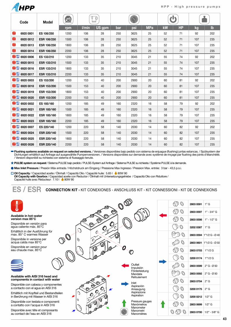
43
H P P › H i g h p r e s s u r e p u m p s
Code Modelrpm l/min US gpm bar psi MPa kW HP kg lb
6920 0001 ES 106/250 1200 106 28 250 3625 25 52 71 92 202
6920 0012 ESR 106/250 1500 106 28 250 3625 25 52 71 107 235
6920 0013 ESR 106/250 1800 106 28 250 3625 25 52 71 107 235
6920 0014 ESR 106/250 2200 106 28 250 3625 25 52 71 107 235
6920 0006 ES 133/210 1200 133 35 210 3045 21 55 74 92 202
6920 0015 ESR 133/210 1500 133 35 210 3045 21 55 74 107 235
6920 0016 ESR 133/210 1800 133 35 210 3045 21 55 74 107 235
6920 0017 ESR 133/210 2200 133 35 210 3045 21 55 74 107 235
6920 0003 ES 153/200 1200 153 40 200 2900 20 60 81 92 202
6920 0018 ESR 153/200 1500 153 40 200 2900 20 60 81 107 235
6920 0019 ESR 153/200 1800 153 40 200 2900 20 60 81 107 235
6920 0020 ESR 153/200 2200 153 40 200 2900 20 60 81 107 235
6920 0002 ES 185/160 1200 185 49 160 2320 16 58 79 92 202
6920 0021 ESR 185/160 1500 185 49 160 2320 16 58 79 107 235
6920 0022 ESR 185/160 1800 185 49 160 2320 16 58 79 107 235
6920 0023 ESR 185/160 2200 185 49 160 2320 16 58 79 107 235
6920 0007 ES 220/140 1200 220 58 140 2030 14 60 82 92 202
6920 0024 ESR 220/140 1500 220 58 140 2030 14 60 82 107 235
6920 0025 ESR 220/140 1800 220 58 140 2030 14 60 82 107 235
6920 0026 ESR 220/140 2200 220 58 140 2030 14 60 82 107 235
CONNECTION KIT › KIT CONEXIONES › ANSCHLUSS KIT › KIT CONNESSIONI › KIT DE CONNEXIONSES / ESR
Max Inlet Pressure / Presión Máx entrada / Höchstdruck am Eingang / Pressione Max Ingresso / Pression Max. entrée: 3 bar - 43,5 p.s.i.
Flushing systems available on request on selected versions. / Versiones disponibles bajo pedido con sistema de enjuague (flushing) juntas estancas. / Spülsystem der Dichtungen erhältlich auf Anfrage auf ausgewählte Pumpenversionen. / Versions disponibles sur demande avec système de rinçage par flushing des joints d’étanchéité. / Versioni disponibili su richiesta con sistema di flussaggio tenute.
Available in hot-waterversion max 85°CDisponible en versión paraagua caliente máx. 85°CErhältlich in der Ausführung für max. 85° C warmes WasserDisponibile in versione per acqua calda max 85°CDisponible en version pour eau chaude max. 85°C
Available with AISI 316 head and components in contact with waterDisponible con cabeza y componentesa contacto con el agua en AISI 316Erhältlich mit Kopfteil und Bestandteilen in Berührung mit Wasser in AISI 316Disponibile con testata e componenti a contatto con l’acqua in AISI 316Disponible avec tête et composants au contact de l’eau en AISI 316
OutletImpulsiónFörderleistungMandataRefoulement
InletAspiraciónAnsaugungAspirazioneAspiration
Pressure gaugesManómetrosManometerManometriManomètres
2803 0591 1” G
2803 0597 1” - 3/4” G
2803 0598 1” - 1/2” G
3202 0387 1” G
2803 0594 1”1/2 G - Ø 40
2803 0601 1”1/2 G - Ø 50
2803 0703 1”1/2 G
3200 0174 1”1/2 G
2803 0599 2” G - Ø 50
2803 0592 2” G - Ø 50
2803 0704 2” G
3200 0175 2” G
3200 0212 1/2” G
2803 0699 1/2” G
2803 0700 1/2” - 3/8” G
Oil Capacity / Capacidad aceite / Ölinhalt / Capacità Olio / Capacité huile: 5.65 l 80W 90Oil Capacity with Gearbox / Capacidad aceite con Reductor / Ölinhalt mit Untersetzungsgetriebe / Capacità Olio con Riduttore / Capacité huile avec Réducteur: 7.10 l 80W 90
PULSE system on request / Sistema PULSE bajo pedido / PULSE-System auf Anfrage / Sistema PULSE su richiesta / Système PULSE à la demande.
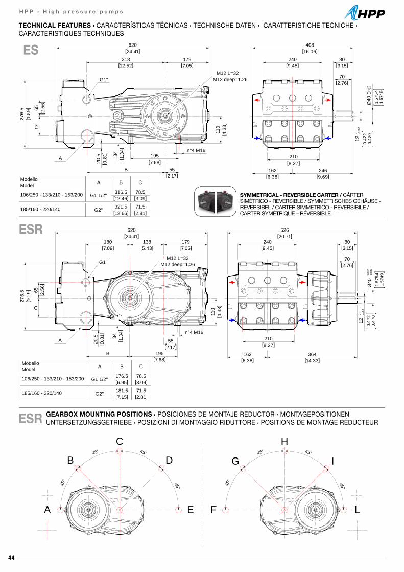
44
H P P › H i g h p r e s s u r e p u m p s
620[24.41]
180[7.09]
138[5.43]
179[7.05]
276.
5[ 1
0.9] 65
[ 2.5
6]
[7.68]B
C
195
55[2.17]
n°4 M16
110
20.5
[ 0.8
1]
526[20.71]
240[9.45]
80[3.15]
70[2.76]
210[8.27]
364[14.33]
162[6.38]
[ 4.3
3]
A
G1"M12 L=32
M12 deep=1.26
Ø40
+0.0
15+0
.002
1.57
541.
5749
12-0 -0
.052
0.47
20.
470
34[ 1
.34]
ModelloModel A
G1 1/2"
G2"
176.5 78.5
B C
106/250 - 133/210 - 153/200
181.5 71.5185/160 - 220/140
[6.95] [3.09]
[7.15] [2.81]
620[24.41]
318[12.52]
179[7.05]
276.
5[ 1
0.9] 65
[ 2.5
6]
195[7.68]
B 55[2.17]
n°4 M16
20.5
[ 0.8
1]
408[16.06]
240[9.45]
80[3.15]
70[2.76]
210[8.27]
246[9.69]
162[6.38]
110
[ 4.3
3]
A
G1"M12 L=32
M12 deep=1.26
Ø40
+0.0
15+0
.002
1.57
541.
5749
12-0 -0
.052
0.47
20.
470
34[ 1
.34]
C
ModelloModel A
G1 1/2"
G2"
316.5 78.5
B C
106/250 - 133/210 - 153/200
321.5 71.5185/160 - 220/140
[12.46] [3.09]
[12.66] [2.81]
GEARBOX MOUNTING POSITIONS › POSICIONES DE MONTAJE REDUCTOR › MONTAGEPOSITIONEN UNTERSETZUNGSGETRIEBE › POSIZIONI DI MONTAGGIO RIDUTTORE › POSITIONS DE MONTAGE RÉDUCTEUR
TECHNICAL FEATURES › CARACTERÍSTICAS TÉCNICAS › TECHNISCHE DATEN › CARATTERISTICHE TECNICHE ›CARACTERISTIQUES TECHNIQUES
ESR
SYMMETRICAL - REVERSIBLE CARTER / CÁRTER SIMÉTRICO - REVERSIBLE / SYMMETRISCHES GEHÄUSE - REVERSIBEL / CARTER SIMMETRICO - REVERSIBILE / CARTER SYMÉTRIQUE – RÉVERSIBLE.
ESR
ES
45° 45°
45° 45°
45° 45°
45° 45°
A
B
C
D
E L
I
H
G
F
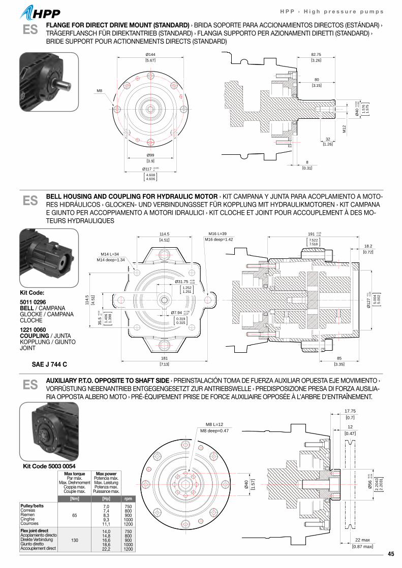
45
H P P › H i g h p r e s s u r e p u m p s
17.75[0.7]
22 max[0.87 max]
12[0.47]
Ø56
-0.0
1-0
.04
2.20
432.
2031
Ø40
[ 1.5
7]
M8 L=12M8 deep=0.47
17.75[0.7]
22 max[0.87 max]
12[0.47]
Ø56
-0.0
1-0
.04
2.20
432.
2031
Ø40
[ 1.5
7]
M8 L=12M8 deep=0.47
ES
ES
ES
Kit Code 5003 0054Max torque
Par máx.Max. Drehmoment
Coppia max.Couple max.
Max powerPotencia máx.Max. LeistungPotenza max.
Puissance max.[Nm] [Hp] rpm
Pulley/beltsCorreasRiemenCinghieCourroies
65
7,07,48,39,311,1
75080090010001200
Flex joint directAcoplamiento directoDirekte VerbindungGiunto direttoAccouplement direct
130
14,014,816,618,622,2
75080090010001200
82.75[3.26]
Ø144[5.67]
Ø99[3.9]
80[3.15]
32[1.26]
8[0.31]
M12
M8
Ø117 +0.035-0
4.6084.606
Ø40
+0.0
18+0
.002
1.57
61.
575
114.5[4.51]
18.2[0.72]
114.
5[ 4
.51]
181[7.13]
85[3.35]
M14 L=34M14 deep=1.34
M16 L=39M16 deep=1.42
191 +0.05-0.05
7.5227.518
Ø31.75 +0.05+0.03
1.2521.251
Ø7.94 +0.156+0.07
0.3190.315
Ø12
7+0
.1+0
.05
5.00
45.
002
35.5
+0.0
2+0
1.40
61.
398
BELL HOUSING AND COUPLING FOR HYDRAULIC MOTOR › KIT CAMPANA Y JUNTA PARA ACOPLAMIENTO A MOTO-RES HIDRÁULICOS › GLOCKEN- UND VERBINDUNGSSET FÜR KOPPLUNG MIT HYDRAULIKMOTOREN › KIT CAMPANA E GIUNTO PER ACCOPPIAMENTO A MOTORI IDRAULICI › KIT CLOCHE ET JOINT POUR ACCOUPLEMENT À DES MO-TEURS HYDRAULIQUES
AUXILIARY P.T.O. OPPOSITE TO SHAFT SIDE › PREINSTALACIÓN TOMA DE FUERZA AUXILIAR OPUESTA EJE MOVIMIENTO › VORRÜSTUNG NEBENANTRIEB ENTGEGENGESETZT ZUR ANTRIEBSWELLE › PREDISPOSIZIONE PRESA DI FORZA AUSILIA-RIA OPPOSTA ALBERO MOTO › PRÉ-ÉQUIPEMENT PRISE DE FORCE AUXILIAIRE OPPOSÉE À L’ARBRE D’ENTRAÎNEMENT.
FLANGE FOR DIRECT DRIVE MOUNT (STANDARD) › BRIDA SOPORTE PARA ACCIONAMIENTOS DIRECTOS (ESTÁNDAR) › TRÄGERFLANSCH FÜR DIREKTANTRIEB (STANDARD) › FLANGIA SUPPORTO PER AZIONAMENTI DIRETTI (STANDARD) › BRIDE SUPPORT POUR ACTIONNEMENTS DIRECTS (STANDARD)
SAE J 744 C
Kit Code:5011 0296 BELL / CAMPANAGLOCKE / CAMPANACLOCHE1221 0060 COUPLING / JUNTAKOPPLUNG / GIUNTOJOINT
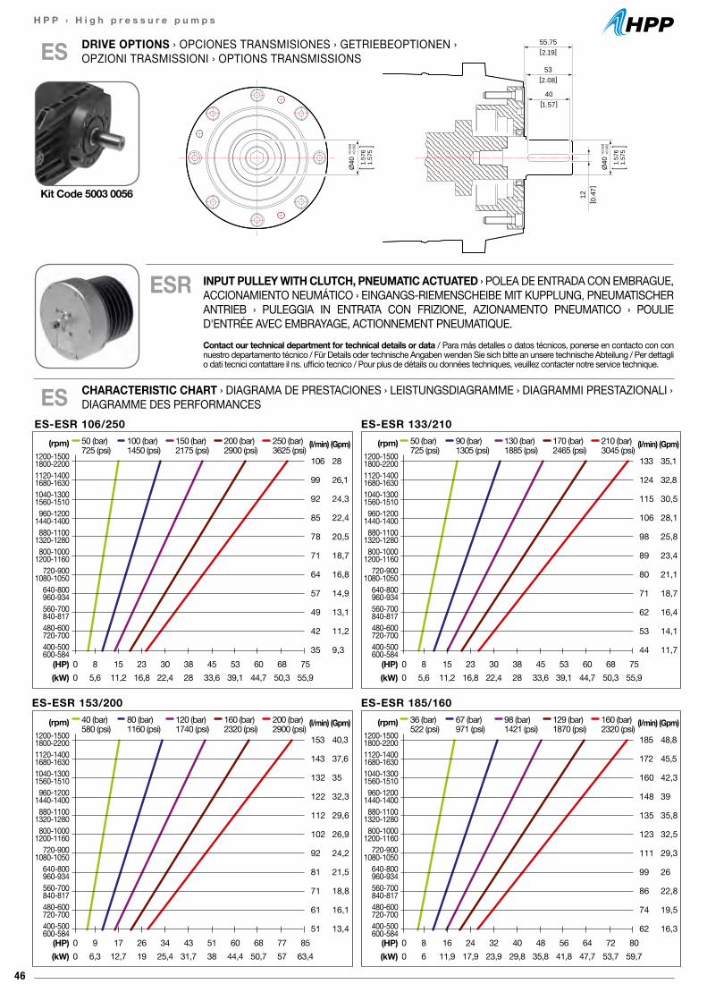
46
H P P › H i g h p r e s s u r e p u m p s
ES-ESR 106/250(l/min)
106
99
92
85
78
71
64
57
49
42
35
(Gpm)
28
26,1
24,3
22,4
20,5
18,7
16,8
14,9
13,1
11,2
9,3
50 (bar) 100 (bar) 150 (bar) 200 (bar) 250 (bar)725 (psi) 1450 (psi) 2175 (psi) 2900 (psi) 3625 (psi)
(HP) 0 8 15 23 30 38 45 53 60 68 75(kW) 0 5,6 11,2 16,8 22,4 28 33,6 39,1 44,7 50,3 55,9
(rpm)1200-15001800-22001120-14001680-16301040-13001560-1510960-1200
1440-1400880-1100
1320-1280800-1000
1200-1160720-900
1080-1050640-800960-934560-700840-817480-600720-700400-500600-584
ES-ESR 133/210(l/min)
133
124
115
106
98
89
80
71
62
53
44
(Gpm)
35,1
32,8
30,5
28,1
25,8
23,4
21,1
18,7
16,4
14,1
11,7
50 (bar) 90 (bar) 130 (bar) 170 (bar) 210 (bar)725 (psi) 1305 (psi) 1885 (psi) 2465 (psi) 3045 (psi)
(HP) 0 8 15 23 30 38 45 53 60 68 75(kW) 0 5,6 11,2 16,8 22,4 28 33,6 39,1 44,7 50,3 55,9
(rpm)1200-15001800-22001120-14001680-16301040-13001560-1510960-1200
1440-1400880-1100
1320-1280800-1000
1200-1160720-900
1080-1050640-800960-934560-700840-817480-600720-700400-500600-584
ES-ESR 153/200(l/min)
153
143
132
122
112
102
92
81
71
61
51
(Gpm)
40,3
37,6
35
32,3
29,6
26,9
24,2
21,5
18,8
16,1
13,4
40 (bar) 80 (bar) 120 (bar) 160 (bar) 200 (bar)580 (psi) 1160 (psi) 1740 (psi) 2320 (psi) 2900 (psi)
(HP) 0 9 17 26 34 43 51 60 68 77 85(kW) 0 6,3 12,7 19 25,4 31,7 38 44,4 50,7 57 63,4
(rpm)1200-15001800-22001120-14001680-16301040-13001560-1510960-1200
1440-1400880-1100
1320-1280800-1000
1200-1160720-900
1080-1050640-800960-934560-700840-817480-600720-700400-500600-584
ES-ESR 185/160(l/min)
185
172
160
148
135
123
111
99
86
74
62
(Gpm)
48,8
45,5
42,3
39
35,8
32,5
29,3
26
22,8
19,5
16,3
36 (bar) 67 (bar) 98 (bar) 129 (bar) 160 (bar)522 (psi) 971 (psi) 1421 (psi) 1870 (psi) 2320 (psi)
(HP) 0 8 16 24 32 40 48 56 64 72 80(kW) 0 6 11,9 17,9 23,9 29,8 35,8 41,8 47,7 53,7 59,7
(rpm)1200-15001800-22001120-14001680-16301040-13001560-1510960-1200
1440-1400880-1100
1320-1280800-1000
1200-1160720-900
1080-1050640-800960-934560-700840-817480-600720-700400-500600-584
DRIVE OPTIONS › OPCIONES TRANSMISIONES › GETRIEBEOPTIONEN › OPZIONI TRASMISSIONI › OPTIONS TRANSMISSIONSES 55.75
[2.19]
12[ 0
.47]
53[2.08]
40[1.57]
Ø40
+0.0
18+0
.002
1.57
61.
575
Ø40
+0.0
18+0
.002
1.57
61.
575
CHARACTERISTIC CHART › DIAGRAMA DE PRESTACIONES › LEISTUNGSDIAGRAMME › DIAGRAMMI PRESTAZIONALI › DIAGRAMME DES PERFORMANCESES
Kit Code 5003 0056
ESR INPUT PULLEY WITH CLUTCH, PNEUMATIC ACTUATED › POLEA DE ENTRADA CON EMBRAGUE, ACCIONAMIENTO NEUMÁTICO › EINGANGS-RIEMENSCHEIBE MIT KUPPLUNG, PNEUMATISCHER ANTRIEB › PULEGGIA IN ENTRATA CON FRIZIONE, AZIONAMENTO PNEUMATICO › POULIE D'ENTRÉE AVEC EMBRAYAGE, ACTIONNEMENT PNEUMATIQUE.Contact our technical department for technical details or data / Para más detalles o datos técnicos, ponerse en contacto con con nuestro departamento técnico / Für Details oder technische Angaben wenden Sie sich bitte an unsere technische Abteilung / Per dettagli o dati tecnici contattare il ns. ufficio tecnico / Pour plus de détails ou données techniques, veuillez contacter notre service technique.
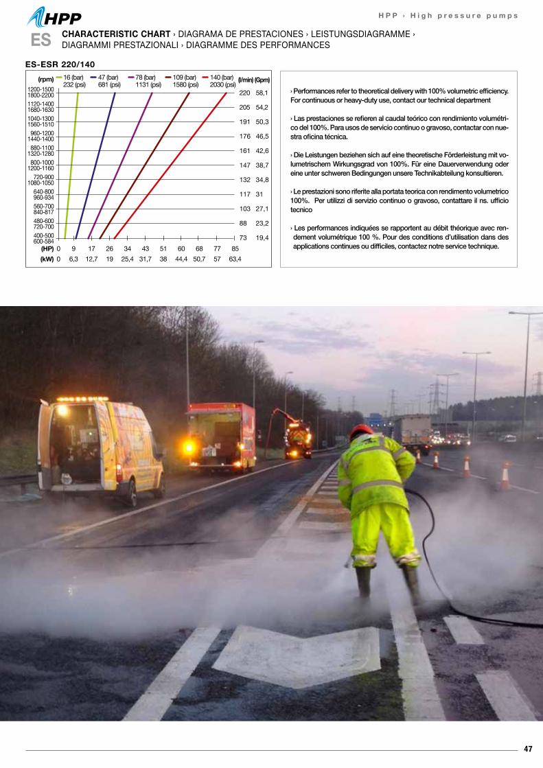
47
H P P › H i g h p r e s s u r e p u m p s
CHARACTERISTIC CHART › DIAGRAMA DE PRESTACIONES › LEISTUNGSDIAGRAMME ›DIAGRAMMI PRESTAZIONALI › DIAGRAMME DES PERFORMANCESES
› Performances refer to theoretical delivery with 100% volumetric efficiency. For continuous or heavy-duty use, contact our technical department
› Las prestaciones se refieren al caudal teórico con rendimiento volumétri-co del 100%. Para usos de servicio continuo o gravoso, contactar con nue-stra oficina técnica.
› Die Leistungen beziehen sich auf eine theoretische Förderleistung mit vo-lumetrischem Wirkungsgrad von 100%. Für eine Dauerverwendung oder eine unter schweren Bedingungen unsere Technikabteilung konsultieren.
› Le prestazioni sono riferite alla portata teorica con rendimento volumetrico 100%. Per utilizzi di servizio continuo o gravoso, contattare il ns. ufficio tecnico
› Les performances indiquées se rapportent au débit théorique avec ren-dement volumétrique 100 %. Pour des conditions d’utilisation dans des applications continues ou difficiles, contactez notre service technique.
ES-ESR 220/140(l/min)
220
205
191
176
161
147
132
117
103
88
73
(Gpm)
58,1
54,2
50,3
46,5
42,6
38,7
34,8
31
27,1
23,2
19,4
16 (bar) 47 (bar) 78 (bar) 109 (bar) 140 (bar)232 (psi) 681 (psi) 1131 (psi) 1580 (psi) 2030 (psi)
(HP) 0 9 17 26 34 43 51 60 68 77 85(kW) 0 6,3 12,7 19 25,4 31,7 38 44,4 50,7 57 63,4
(rpm)1200-15001800-22001120-14001680-16301040-13001560-1510960-1200
1440-1400880-1100
1320-1280800-1000
1200-1160720-900
1080-1050640-800960-934560-700840-817480-600720-700400-500600-584
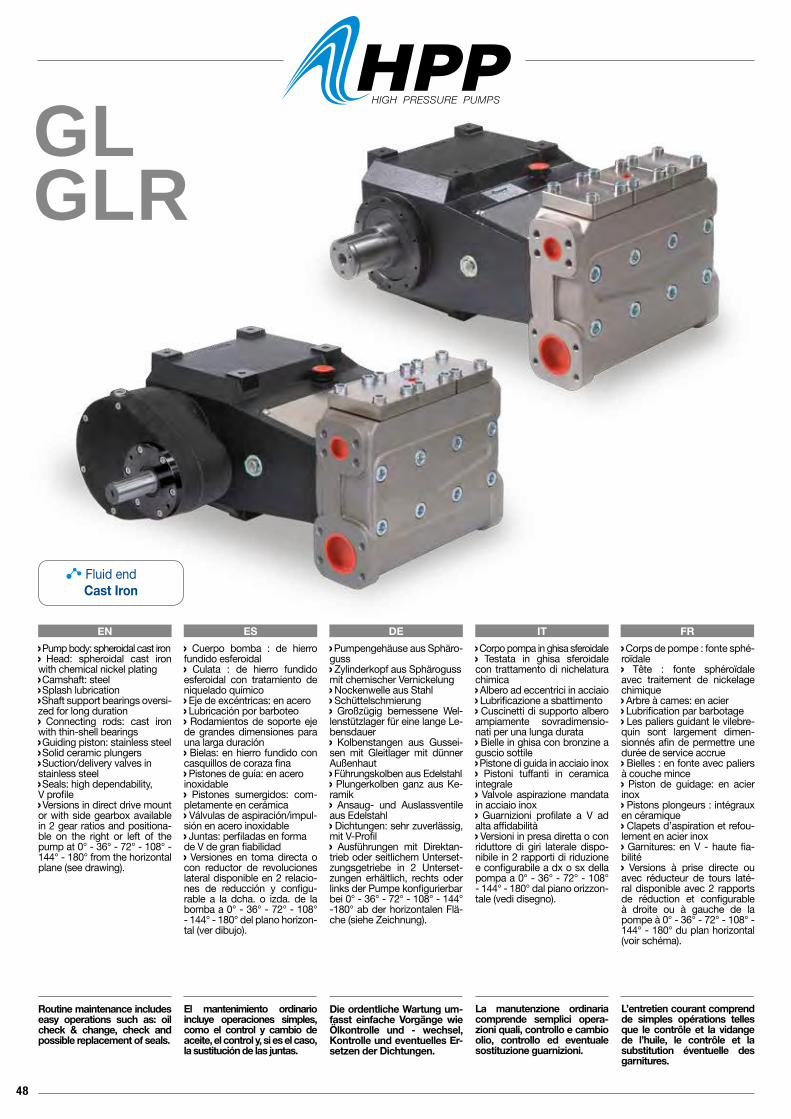
48
GLGLR
EN ES DE IT FR Corpo pompa in ghisa sferoidale Testata in ghisa sferoidale con trattamento di nichelatura chimica Albero ad eccentrici in acciaio Lubrificazione a sbattimento Cuscinetti di supporto albero ampiamente sovradimensio-nati per una lunga durata Bielle in ghisa con bronzine a guscio sottile Pistone di guida in acciaio inox Pistoni tuffanti in ceramica integrale Valvole aspirazione mandata in acciaio inox Guarnizioni profilate a V ad alta affidabilità Versioni in presa diretta o con riduttore di giri laterale dispo-nibile in 2 rapporti di riduzione e configurabile a dx o sx della pompa a 0° - 36° - 72° - 108° - 144° - 180° dal piano orizzon-tale (vedi disegno).
La manutenzione ordinaria comprende semplici opera-zioni quali, controllo e cambio olio, controllo ed eventuale sostituzione guarnizioni.
Pump body: spheroidal cast iron Head: spheroidal cast iron with chemical nickel plating Camshaft: steel Splash lubrication Shaft support bearings oversi-zed for long duration Connecting rods: cast iron with thin-shell bearings Guiding piston: stainless steel Solid ceramic plungers Suction/delivery valves instainless steel Seals: high dependability, V profile Versions in direct drive mount or with side gearbox available in 2 gear ratios and positiona-ble on the right or left of the pump at 0° - 36° - 72° - 108° - 144° - 180° from the horizontal plane (see drawing).
Routine maintenance includes easy operations such as: oil check & change, check and possible replacement of seals.
Cuerpo bomba : de hierro fundido esferoidal Culata : de hierro fundido esferoidal con tratamiento de niquelado químico Eje de excéntricas: en acero Lubricación por barboteo Rodamientos de soporte eje de grandes dimensiones para una larga duración Bielas: en hierro fundido con casquillos de coraza fina Pistones de guía: en aceroinoxidable Pistones sumergidos: com-pletamente en cerámica Válvulas de aspiración/impul-sión en acero inoxidable Juntas: perfiladas en forma de V de gran fiabilidad Versiones en toma directa o con reductor de revoluciones lateral disponible en 2 relacio-nes de reducción y configu-rable a la dcha. o izda. de la bomba a 0° - 36° - 72° - 108° - 144° - 180° del plano horizon-tal (ver dibujo).
El mantenimiento ordinario incluye operaciones simples, como el control y cambio de aceite, el control y, si es el caso, la sustitución de las juntas.
Pumpengehäuse aus Sphäro-guss Zylinderkopf aus Sphärogussmit chemischer Vernickelung Nockenwelle aus Stahl Schüttelschmierung Großzügig bemessene Wel-lenstützlager für eine lange Le-bensdauer Kolbenstangen aus Gussei-sen mit Gleitlager mit dünner Außenhaut Führungskolben aus Edelstahl Plungerkolben ganz aus Ke-ramik Ansaug- und Auslassventile aus Edelstahl Dichtungen: sehr zuverlässig, mit V-Profil Ausführungen mit Direktan-trieb oder seitlichem Unterset-zungsgetriebe in 2 Unterset-zungen erhältlich, rechts oder links der Pumpe konfigurierbarbei 0° - 36° - 72° - 108° - 144° -180° ab der horizontalen Flä-che (siehe Zeichnung).
Die ordentliche Wartung um-fasst einfache Vorgänge wie Ölkontrolle und - wechsel, Kontrolle und eventuelles Er-setzen der Dichtungen.
Corps de pompe : fonte sphé-roïdale Tête : fonte sphéroïdale avec traitement de nickelage chimique Arbre à cames: en acier Lubrification par barbotage Les paliers guidant le vilebre-quin sont largement dimen-sionnés afin de permettre une durée de service accrue Bielles : en fonte avec paliers à couche mince Piston de guidage: en acier inox Pistons plongeurs : intégraux en céramique Clapets d’aspiration et refou-lement en acier inox Garnitures: en V - haute fia-bilité Versions à prise directe ou avec réducteur de tours laté-ral disponible avec 2 rapports de réduction et configurable à droite ou à gauche de la pompe à 0° - 36° - 72° - 108° - 144° - 180° du plan horizontal (voir schéma).
L’entretien courant comprend de simples opérations telles que le contrôle et la vidange de l’huile, le contrôle et la substitution éventuelle des garnitures.
Fluid endCast Iron
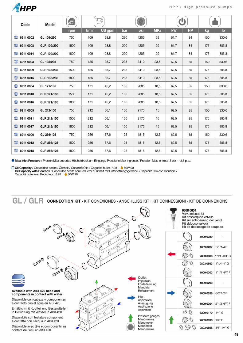
49
H P P › H i g h p r e s s u r e p u m p s
Code Modelrpm l/min US gpm bar psi MPa kW HP kg lb
6911 0002 GL 109/290 750 109 28,8 290 4205 29 61,7 84 150 330,6
6911 0008 GLR 109/290 1500 109 28,8 290 4205 29 61,7 84 175 385,8
6911 0014 GLR 109/290 1800 109 28,8 290 4205 29 61,7 84 175 385,8
6911 0003 GL 135/235 750 135 35,7 235 3410 23,5 62,5 85 150 330,6
6911 0009 GLR 135/235 1500 135 35,7 235 3410 23,5 62,5 85 175 385,8
6911 0015 GLR 135/235 1800 135 35,7 235 3410 23,5 62,5 85 175 385,8
6911 0004 GL 171/185 750 171 45,2 185 2685 18,5 62,5 85 150 330,6
6911 0010 GLR 171/185 1500 171 45,2 185 2685 18,5 62,5 85 175 385,8
6911 0016 GLR 171/185 1800 171 45,2 185 2685 18,5 62,5 85 175 385,8
6911 0005 GL 212/150 750 212 56,1 150 2175 15 62,5 85 150 330,6
6911 0011 GLR 212/150 1500 212 56,1 150 2175 15 62,5 85 175 385,8
6911 0017 GLR 212/150 1800 212 56,1 150 2175 15 62,5 85 175 385,8
6911 0006 GL 256/125 750 256 67,6 125 1815 12,5 62,5 85 150 330,6
6911 0012 GLR 256/125 1500 256 67,6 125 1815 12,5 62,5 85 175 385,8
6911 0018 GLR 256/125 1800 256 67,6 125 1815 12,5 62,5 85 175 385,8
CONNECTION KIT › KIT CONEXIONES › ANSCHLUSS KIT › KIT CONNESSIONI › KIT DE CONNEXIONSGL / GLR
Max Inlet Pressure / Presión Máx entrada / Höchstdruck am Eingang / Pressione Max Ingresso / Pression Max. entrée: 3 bar - 43,5 p.s.i.
Available with AISI 420 head and components in contact with waterDisponible con cabeza y componentes a contacto con el agua en AISI 420Erhältlich mit Kopfteil und Bestandteilen in Berührung mit Wasser in AISI 420Disponibile con testata e componenti a contatto con l’acqua in AISI 420Disponible avec tête et composants au contact de l’eau en AISI 420
0608 0054 Valve release kitKit desbloqueo valvulaKit zur entsperrung der ventilKit sblocco valvolaKit de deblocage de soupape
OutletImpulsiónFörderleistungMandataRefoulement
InletAspiraciónAnsaugungAspirazioneAspiration
Pressure gaugesManómetrosManometerManometriManomètres
1009 0289 -
1009 0287 G 1”1/4 F
2803 0600 1”1/4 - 3/4” G
2803 0593 1”1/4 - 1” G
1009 0303 1”1/4 NPT F
1009 0290 -
1009 0288 G 2”1/2 F
1009 0304 2”1/2 NPT F
3200 0170 1/4” G
2803 0696 1/4” G
2803 0698 3/8”-1/4” G
Oil Capacity / Capacidad aceite / Ölinhalt / Capacità Olio / Capacité huile: 7.98 l 80W 90Oil Capacity with Gearbox / Capacidad aceite con Reductor / Ölinhalt mit Untersetzungsgetriebe / Capacità Olio con Riduttore / Capacité huile avec Réducteur: 8.98 l 80W 90
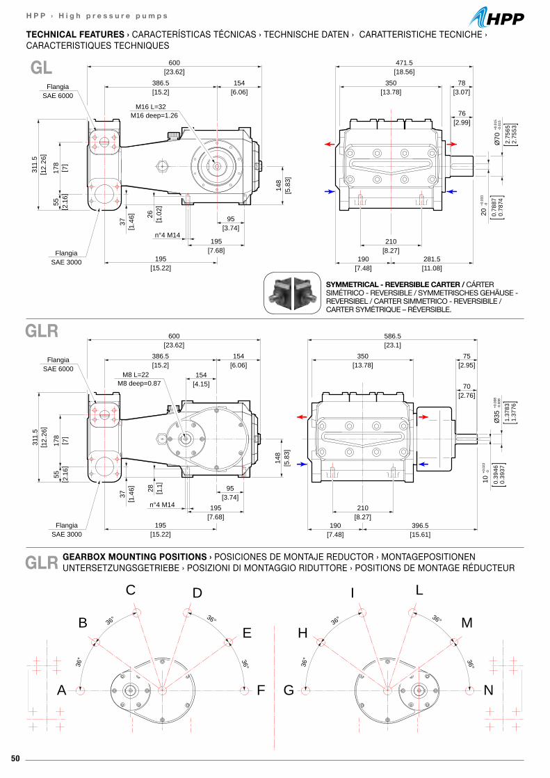
50
H P P › H i g h p r e s s u r e p u m p s
36° 36°
36° 36°
A
B
C D
F
E
N
M
LI
G
H36° 36°
36° 36°
[3.74]95
[2.95]75
[2.76]70
[7.68]195
[15.22]195
[23.62]600
[15.2]386.5
[13.78]350
[23.1]586.5
[15.61]396.5
[7.48]190
[8.27]210
[6.06]154
[4.15]154
n°4 M14
[5.8
3]14
8
SAE 3000Flangia
SAE 6000Flangia
[ 12.
26]
311.
5
[ 7]
178
[ 2.1
6]55
[ 1.4
6]37 [ 1
.1]
28
10+0
.022
-0
0.39
460.
3937
Ø35
+0.0
08-0
.008
1.37
831.
3776
M8 L=22M8 deep=0.87
[3.74]95
[3.07]78
[2.99]76
[7.68]195
[15.22]195
[23.62]600
[15.2]386.5
[13.78]350
[18.56]471.5
[11.08]281.5
[7.48]190
[8.27]210
[6.06]154
n°4 M14
[5.8
3]14
8
SAE 3000Flangia
SAE 6000Flangia
[ 12.
26]
311.
5
[ 7]
178
[ 2.1
6]55
[ 1.4
6]37
20+0
.033
-0
0.78
870.
7874
Ø70
+0.0
15-0
.015
2.75
652.
7553
M16 L=32M16 deep=1.26
[ 1.0
2]26
GEARBOX MOUNTING POSITIONS › POSICIONES DE MONTAJE REDUCTOR › MONTAGEPOSITIONEN UNTERSETZUNGSGETRIEBE › POSIZIONI DI MONTAGGIO RIDUTTORE › POSITIONS DE MONTAGE RÉDUCTEUR
TECHNICAL FEATURES › CARACTERÍSTICAS TÉCNICAS › TECHNISCHE DATEN › CARATTERISTICHE TECNICHE ›CARACTERISTIQUES TECHNIQUES
GL
GLR
GLR
SYMMETRICAL - REVERSIBLE CARTER / CÁRTER SIMÉTRICO - REVERSIBLE / SYMMETRISCHES GEHÄUSE - REVERSIBEL / CARTER SIMMETRICO - REVERSIBILE / CARTER SYMÉTRIQUE – RÉVERSIBLE.
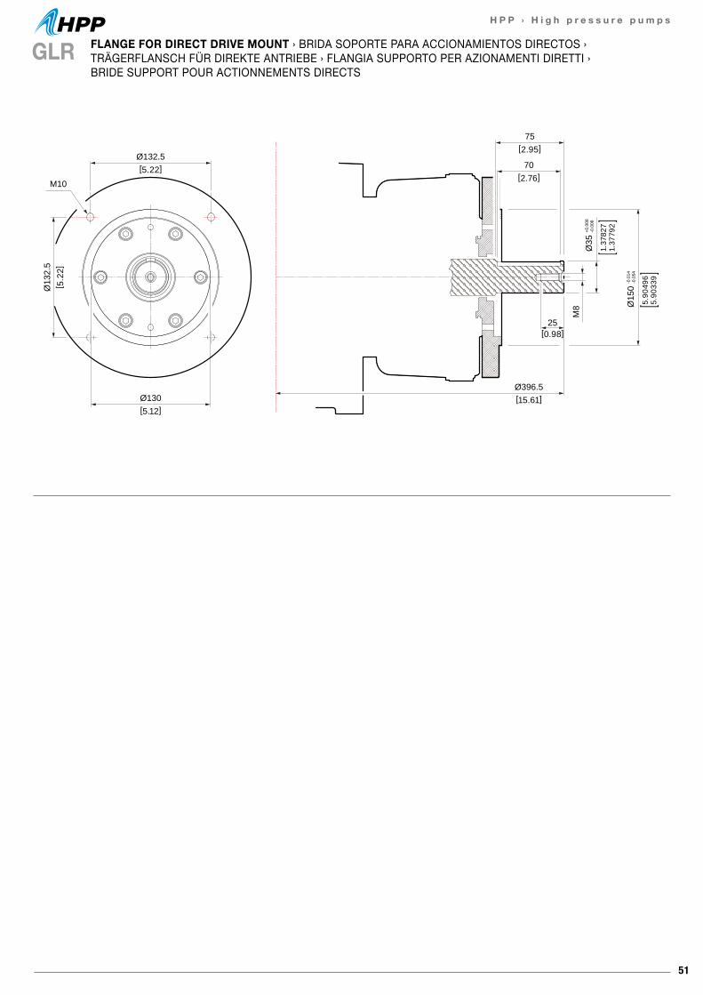
51
H P P › H i g h p r e s s u r e p u m p s
Ø132.5[5.22]
Ø130[5.12]
Ø13
2.5
[ 5.2
2]
M10
75[2.95]
Ø396.5[15.61]
70[2.76]
25[0.98]
M8
Ø35
+0.0
08-0
.008
1.37
827
1.37
792
Ø15
0-0
.014
-0.0
54
5.90
496
5.90
339
GLR FLANGE FOR DIRECT DRIVE MOUNT › BRIDA SOPORTE PARA ACCIONAMIENTOS DIRECTOS › TRÄGERFLANSCH FÜR DIREKTE ANTRIEBE › FLANGIA SUPPORTO PER AZIONAMENTI DIRETTI › BRIDE SUPPORT POUR ACTIONNEMENTS DIRECTS
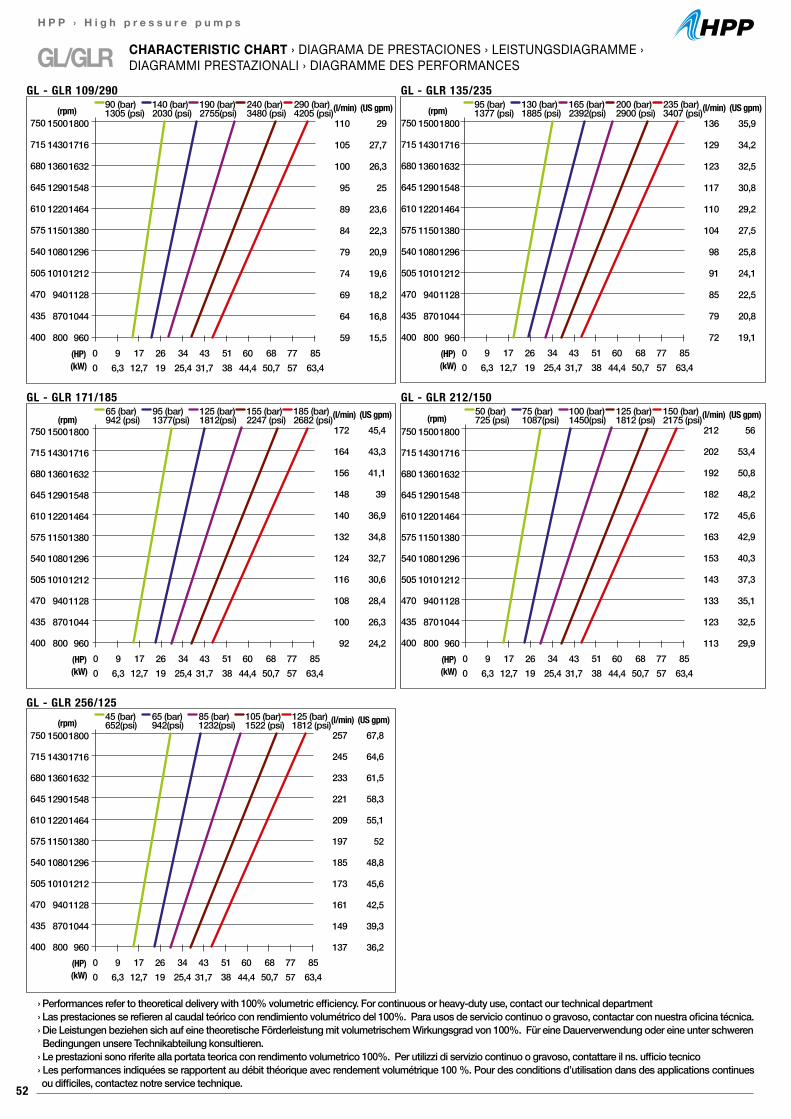
52
H P P › H i g h p r e s s u r e p u m p s
GL/GLR CHARACTERISTIC CHART › DIAGRAMA DE PRESTACIONES › LEISTUNGSDIAGRAMME ›DIAGRAMMI PRESTAZIONALI › DIAGRAMME DES PERFORMANCES
110
105
100
95
89
84
79
74
69
64
59
29
27,7
26,3
25
23,6
22,3
20,9
19,6
18,2
16,8
15,50 17 34 51 68 850 12,7 25,4 38 50,7 63,4
(HP)(kW)
90 (bar)1305 (psi)
140 (bar)2030 (psi)
190 (bar)2755(psi)
240 (bar)3480 (psi)
290 (bar)4205 (psi)(l/min) (US gpm)
GL - GLR 109/290
96,3
2619
4331,7
6044,4
7757
(rpm)750
715
680
645
610
575
540
505
470
435
400
1800
1716
1632
1548
1464
1380
1296
1212
1128
1044
960
1500
1430
1360
1290
1220
1150
1080
1010
940
870
800
750
715
680
645
610
575
540
505
470
435
400
1800
1716
1632
1548
1464
1380
1296
1212
1128
1044
960
1500
1430
1360
1290
1220
1150
1080
1010
940
870
800
136
129
123
117
110
104
98
91
85
79
72
35,9
34,2
32,5
30,8
29,2
27,5
25,8
24,1
22,5
20,8
19,10 17 34 51 68 850 12,7 25,4 38 50,7 63,4
(HP)(kW)
95 (bar)1377 (psi)
130 (bar)1885 (psi)
165 (bar)2392(psi)
200 (bar)2900 (psi)
235 (bar)3407 (psi)(l/min) (US gpm)
GL - GLR 135/235
96,3
2619
4331,7
6044,4
7757
(rpm)
172
164
156
148
140
132
124
116
108
100
92
45,4
43,3
41,1
39
36,9
34,8
32,7
30,6
28,4
26,3
24,20 17 34 51 68 850 12,7 25,4 38 50,7 63,4
(HP)(kW)
65 (bar)942 (psi)
95 (bar)1377(psi)
125 (bar)1812(psi)
155 (bar)2247 (psi)
185 (bar)2682 (psi)(l/min) (US gpm)
GL - GLR 171/185
96,3
2619
4331,7
6044,4
7757
(rpm)750
715
680
645
610
575
540
505
470
435
400
1800
1716
1632
1548
1464
1380
1296
1212
1128
1044
960
1500
1430
1360
1290
1220
1150
1080
1010
940
870
800
257
245
233
221
209
197
185
173
161
149
137
67,8
64,6
61,5
58,3
55,1
52
48,8
45,6
42,5
39,3
36,20 17 34 51 68 850 12,7 25,4 38 50,7 63,4
(HP)(kW)
45 (bar)652(psi)
65 (bar)942(psi)
85 (bar)1232(psi)
105 (bar)1522 (psi)
125 (bar)1812 (psi)(l/min) (US gpm)
GL - GLR 256/125
96,3
2619
4331,7
6044,4
7757
(rpm)750
715
680
645
610
575
540
505
470
435
400
1800
1716
1632
1548
1464
1380
1296
1212
1128
1044
960
1500
1430
1360
1290
1220
1150
1080
1010
940
870
800
212
202
192
182
172
163
153
143
133
123
113
56
53,4
50,8
48,2
45,6
42,9
40,3
37,3
35,1
32,5
29,90 17 34 51 68 850 12,7 25,4 38 50,7 63,4
(HP)(kW)
50 (bar)725 (psi)
75 (bar)1087(psi)
100 (bar)1450(psi)
125 (bar)1812 (psi)
150 (bar)2175 (psi)(l/min) (US gpm)
GL - GLR 212/150
96,3
2619
4331,7
6044,4
7757
(rpm)750
715
680
645
610
575
540
505
470
435
400
1800
1716
1632
1548
1464
1380
1296
1212
1128
1044
960
1500
1430
1360
1290
1220
1150
1080
1010
940
870
800
› Performances refer to theoretical delivery with 100% volumetric efficiency. For continuous or heavy-duty use, contact our technical department› Las prestaciones se refieren al caudal teórico con rendimiento volumétrico del 100%. Para usos de servicio continuo o gravoso, contactar con nuestra oficina técnica.› Die Leistungen beziehen sich auf eine theoretische Förderleistung mit volumetrischem Wirkungsgrad von 100%. Für eine Dauerverwendung oder eine unter schweren Bedingungen unsere Technikabteilung konsultieren.› Le prestazioni sono riferite alla portata teorica con rendimento volumetrico 100%. Per utilizzi di servizio continuo o gravoso, contattare il ns. ufficio tecnico› Les performances indiquées se rapportent au débit théorique avec rendement volumétrique 100 %. Pour des conditions d’utilisation dans des applications continues ou difficiles, contactez notre service technique.
53
H P P › H i g h p r e s s u r e p u m p s
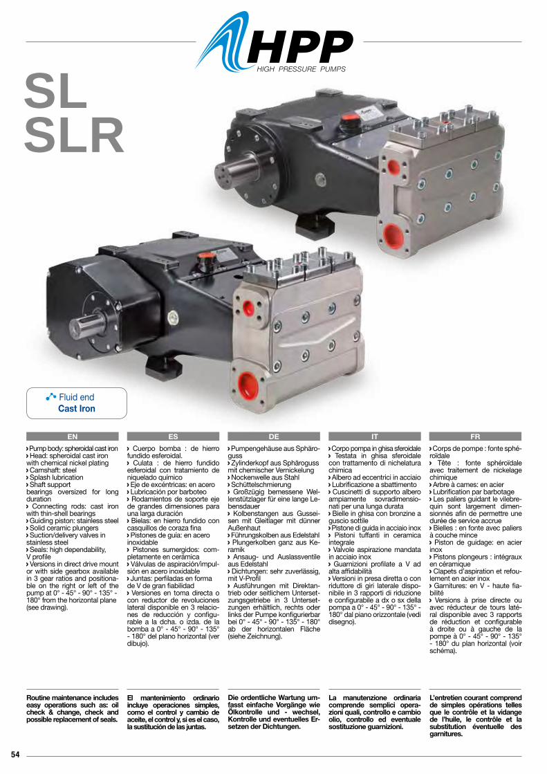
54
SLSLR
EN ES DE IT FR Corpo pompa in ghisa sferoidale Testata in ghisa sferoidale con trattamento di nichelatura chimica Albero ad eccentrici in acciaio Lubrificazione a sbattimento Cuscinetti di supporto albero ampiamente sovradimensio-nati per una lunga durata Bielle in ghisa con bronzine a guscio sottile Pistone di guida in acciaio inox Pistoni tuffanti in ceramica integrale Valvole aspirazione mandata in acciaio inox Guarnizioni profilate a V ad alta affidabilità Versioni in presa diretta o con riduttore di giri laterale dispo-nibile in 3 rapporti di riduzione e configurabile a dx o sx della pompa a 0° - 45° - 90° - 135° - 180° dal piano orizzontale (vedi disegno).
La manutenzione ordinaria comprende semplici opera-zioni quali, controllo e cambio olio, controllo ed eventuale sostituzione guarnizioni.
Pump body: spheroidal cast iron Head: spheroidal cast ironwith chemical nickel plating Camshaft: steel Splash lubrication Shaft support bearings oversized for long duration Connecting rods: cast iron with thin-shell bearings Guiding piston: stainless steel Solid ceramic plungers Suction/delivery valves instainless steel Seals: high dependability, V profile Versions in direct drive mount or with side gearbox available in 3 gear ratios and positiona-ble on the right or left of the pump at 0° - 45° - 90° - 135° -180° from the horizontal plane(see drawing).
Routine maintenance includes easy operations such as: oil check & change, check and possible replacement of seals.
Cuerpo bomba : de hierro fundido esferoidal. Culata : de hierro fundido esferoidal con tratamiento de niquelado químico Eje de excéntricas: en acero Lubricación por barboteo Rodamientos de soporte eje de grandes dimensiones para una larga duración Bielas: en hierro fundido con casquillos de coraza fina Pistones de guía: en aceroinoxidable Pistones sumergidos: com-pletamente en cerámica Válvulas de aspiración/impul-sión en acero inoxidable Juntas: perfiladas en forma de V de gran fiabilidad Versiones en toma directa o con reductor de revoluciones lateral disponible en 3 relacio-nes de reducción y configu-rable a la dcha. o izda. de la bomba a 0° - 45° - 90° - 135° - 180° del plano horizontal (ver dibujo).
El mantenimiento ordinario incluye operaciones simples, como el control y cambio de aceite, el control y, si es el caso, la sustitución de las juntas.
Pumpengehäuse aus Sphäro-guss Zylinderkopf aus Sphärogussmit chemischer Vernickelung Nockenwelle aus Stahl Schüttelschmierung Großzügig bemessene Wel-lenstützlager für eine lange Le-bensdauer Kolbenstangen aus Gussei-sen mit Gleitlager mit dünner Außenhaut Führungskolben aus Edelstahl Plungerkolben ganz aus Ke-ramik Ansaug- und Auslassventile aus Edelstahl Dichtungen: sehr zuverlässig, mit V-Profil Ausführungen mit Direktan-trieb oder seitlichem Unterset-zungsgetriebe in 3 Unterset-zungen erhältlich, rechts oder links der Pumpe konfigurierbar bei 0° - 45° - 90° - 135° - 180° ab der horizontalen Fläche (siehe Zeichnung).
Die ordentliche Wartung um-fasst einfache Vorgänge wie Ölkontrolle und - wechsel, Kontrolle und eventuelles Er-setzen der Dichtungen.
Corps de pompe : fonte sphé-roïdale Tête : fonte sphéroïdale avec traitement de nickelage chimique Arbre à cames: en acier Lubrification par barbotage Les paliers guidant le vilebre-quin sont largement dimen-sionnés afin de permettre une durée de service accrue Bielles : en fonte avec paliers à couche mince Piston de guidage: en acier inox Pistons plongeurs : intégraux en céramique Clapets d’aspiration et refou-lement en acier inox Garnitures: en V - haute fia-bilité Versions à prise directe ou avec réducteur de tours laté-ral disponible avec 3 rapports de réduction et configurable à droite ou à gauche de la pompe à 0° - 45° - 90° - 135° - 180° du plan horizontal (voir schéma).
L’entretien courant comprend de simples opérations telles que le contrôle et la vidange de l’huile, le contrôle et la substitution éventuelle des garnitures.
Fluid endCast Iron
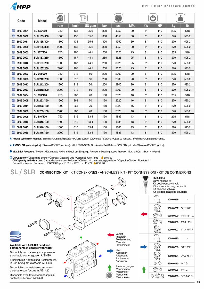
55
H P P › H i g h p r e s s u r e p u m p s
Available with AISI 420 head and components in contact with waterDisponible con cabeza y componentes a contacto con el agua en AISI 420Erhältlich mit Kopfteil und Bestandteilen in Berührung mit Wasser in AISI 420Disponibile con testata e componenti a contatto con l’acqua in AISI 420Disponible avec tête et composants au contact de l’eau en AISI 420
0608 0054 Valve release kitKit desbloqueo valvulaKit zur entsperrung der ventilKit sblocco valvolaKit de deblocage de soupape
OutletImpulsiónFörderleistungMandataRefoulement
InletAspiraciónAnsaugungAspirazioneAspiration
Pressure gaugesManómetrosManometerManometriManomètres
1009 0289 -
1009 0287 G 1”1/4 F
2803 0600 1”1/4 - 3/4” G
2803 0593 1”1/4 - 1” G
1009 0303 1”1/4 NPT F
1009 0290 -
1009 0288 G 2”1/2 F
1009 0304 2”1/2 NPT F
3200 0170 1/4” G
2803 0696 1/4” G
2803 0698 3/8”-1/4” G
Code Modelrpm l/min US gpm bar psi MPa kW HP kg lb
6909 0001 SL 135/300 750 135 35,6 300 4350 30 81 110 235 518
6909 0006 SLR 135/300 1500 135 35,6 300 4350 30 81 110 270 595,2
6909 0011 SLR 135/300 1800 135 35,6 300 4350 30 81 110 270 595,2
6909 0035 SLR 135/300 2200 135 35,6 300 4350 30 81 110 270 595,2
6909 0002 SL 167/250 750 167 44,1 250 3625 25 81 110 235 518
6909 0007 SLR 167/250 1500 167 44,1 250 3625 25 81 110 270 595,2
6909 0012 SLR 167/250 1800 167 44,1 250 3625 25 81 110 270 595,2
6909 0036 SLR 167/250 2200 167 44,1 250 3625 25 81 110 270 595,2
6909 0003 SL 212/200 750 212 56 200 2900 20 81 110 235 518
6909 0008 SLR 212/200 1500 212 56 200 2900 20 81 110 270 595,2
6909 0013 SLR 212/200 1800 212 56 200 2900 20 81 110 270 595,2
6909 0037 SLR 212/200 2200 212 56 200 2900 20 81 110 270 595,2
6909 0004 SL 263/160 750 263 70 160 2320 16 81 110 235 518
6909 0009 SLR 263/160 1500 263 70 160 2320 16 81 110 270 595,2
6909 0014 SLR 263/160 1800 263 70 160 2320 16 81 110 270 595,2
6909 0038 SLR 263/160 2200 263 70 160 2320 16 81 110 270 595,2
6909 0005 SL 316/130 750 316 83,4 130 1885 13 81 110 235 518
6909 0010 SLR 316/130 1500 316 83,4 130 1885 13 81 110 270 595,2
6909 0015 SLR 316/130 1800 316 83,4 130 1885 13 81 110 270 595,2
6909 0039 SLR 316/130 2200 316 83,4 130 1885 13 81 110 270 595,2
Max Inlet Pressure / Presión Máx entrada / Höchstdruck am Eingang / Pressione Max Ingresso / Pression Max. entrée: 3 bar - 43,5 p.s.i.
COOLER system (option) / Sistema COOLER (opcional) / KÜHLER-SYSTEM (Sonderzubehör) / Sistema COOLER (opzionale) / Système COOLER (option).
PULSE system on request / Sistema PULSE bajo pedido / PULSE-System auf Anfrage / Sistema PULSE su richiesta / Système PULSE à la demande.
CONNECTION KIT › KIT CONEXIONES › ANSCHLUSS KIT › KIT CONNESSIONI › KIT DE CONNEXIONSSL / SLR
Oil Capacity / Capacidad aceite / Ölinhalt / Capacità Olio / Capacité huile: 8.98 l 80W 90Oil Capacity with Gearbox / Capacidad aceite con Reductor / Ölinhalt mit Untersetzungsgetriebe / Capacità Olio con Riduttore / Capacité huile avec Réducteur: 1500/1800 rpm 10.50 l - 2200 rpm 11.47 l 80W 90
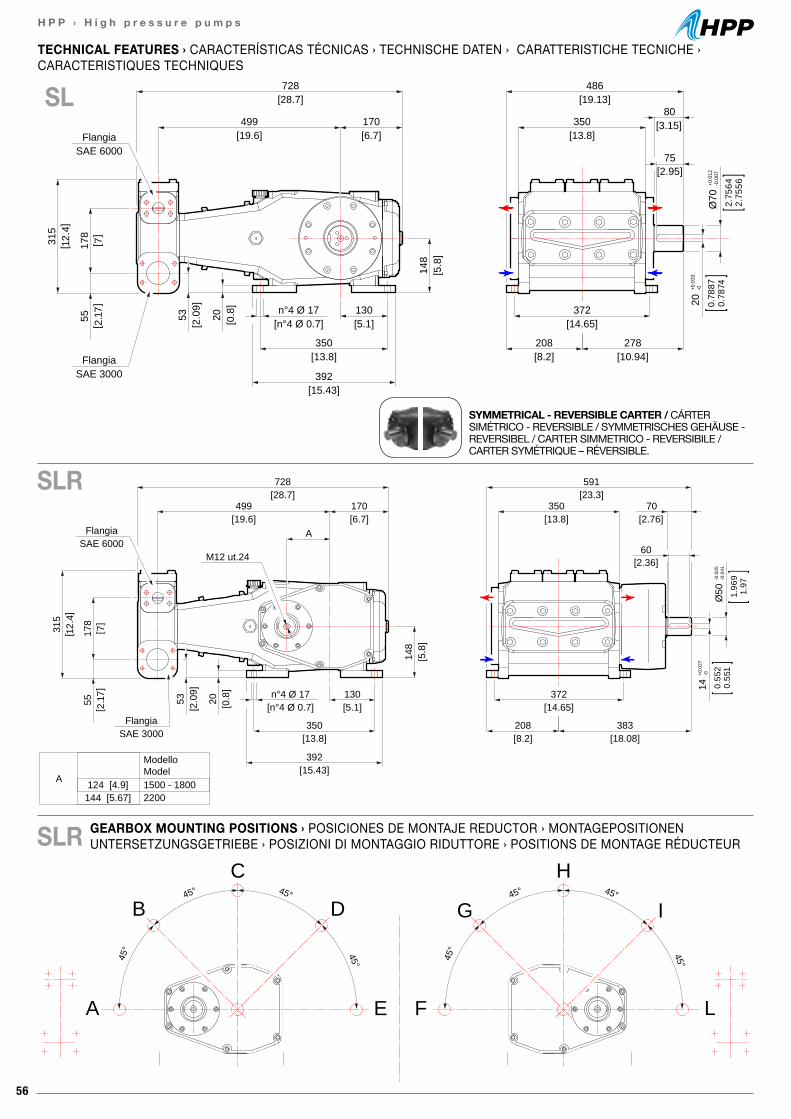
56
H P P › H i g h p r e s s u r e p u m p s
60[2.36]
[23.3]591
[13.8]350
[13.8]350
[15.43]392
[8.2]208
[18.08]383
[5.1]130
[14.65]372
[2.76]70
[28.7]728
[19.6]499
[6.7]170
A
SAE 3000Flangia
[0.8
]20
[2.0
9]53 [n°4 Ø 0.7]
n°4 Ø 17
[5.8
]14
8
M12 ut.24SAE 6000
Flangia
[ 2.1
7]55
[ 12.
4]31
5
[ 7]
178
14+0
.027
-0
0.55
20.
551
Ø50
-0.0
25-0
.041
1.96
91.
97
ModelloModel
A 124 [4.9] 1500 - 1800144 [5.67] 2200
45° 45°
45° 45°
45° 45°
45° 45°
A
B
C
D
E L
I
H
G
F
75[2.95]
[19.13]486
[13.8]350
[13.8]350
[15.43]392
[8.2]208
[10.94]278
[5.1]130
[14.65]372
[3.15]80
[28.7]728
[19.6]499
[6.7]170
SAE 3000Flangia
[0.8
]20
[2.0
9]53 [n°4 Ø 0.7]
n°4 Ø 17
[5.8
]14
8
SAE 6000Flangia
[ 2.1
7]55
[ 12.
4]31
5
[ 7]
178
Ø70
+0.0
12-0
.007
2.75
642.
7556
20+0
.033
-0
0.78
870.
7874
GEARBOX MOUNTING POSITIONS › POSICIONES DE MONTAJE REDUCTOR › MONTAGEPOSITIONEN UNTERSETZUNGSGETRIEBE › POSIZIONI DI MONTAGGIO RIDUTTORE › POSITIONS DE MONTAGE RÉDUCTEUR
TECHNICAL FEATURES › CARACTERÍSTICAS TÉCNICAS › TECHNISCHE DATEN › CARATTERISTICHE TECNICHE ›CARACTERISTIQUES TECHNIQUES
SL
SLR
SLR
SYMMETRICAL - REVERSIBLE CARTER / CÁRTER SIMÉTRICO - REVERSIBLE / SYMMETRISCHES GEHÄUSE - REVERSIBEL / CARTER SIMMETRICO - REVERSIBILE / CARTER SYMÉTRIQUE – RÉVERSIBLE.
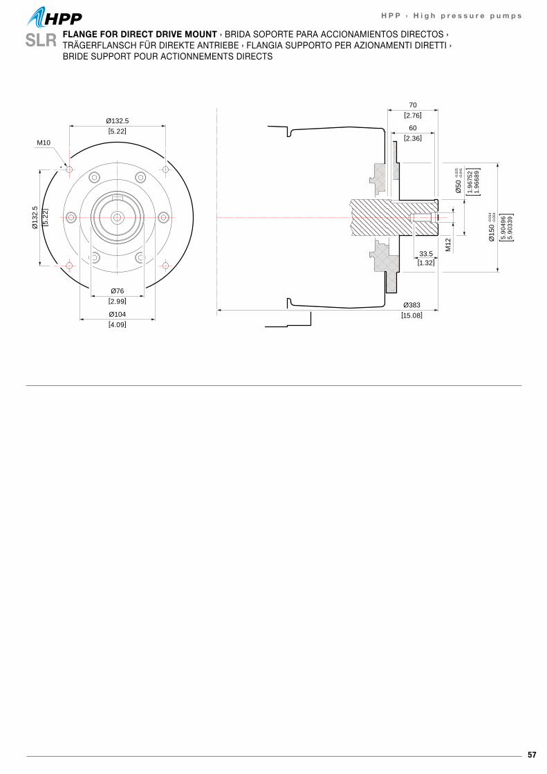
57
H P P › H i g h p r e s s u r e p u m p s
70[2.76]
Ø132.5[5.22]
Ø104[4.09]
Ø383[15.08]
Ø76[2.99]
Ø13
2.5
[ 5.2
2]
60[2.36]
33.5[1.32]
M12
M10
Ø50
-0.0
25-0
.041
1.96
752
1.96
689
Ø15
0-0
.014
-0.0
54
5.90
496
5.90
339
SLR FLANGE FOR DIRECT DRIVE MOUNT › BRIDA SOPORTE PARA ACCIONAMIENTOS DIRECTOS › TRÄGERFLANSCH FÜR DIREKTE ANTRIEBE › FLANGIA SUPPORTO PER AZIONAMENTI DIRETTI › BRIDE SUPPORT POUR ACTIONNEMENTS DIRECTS
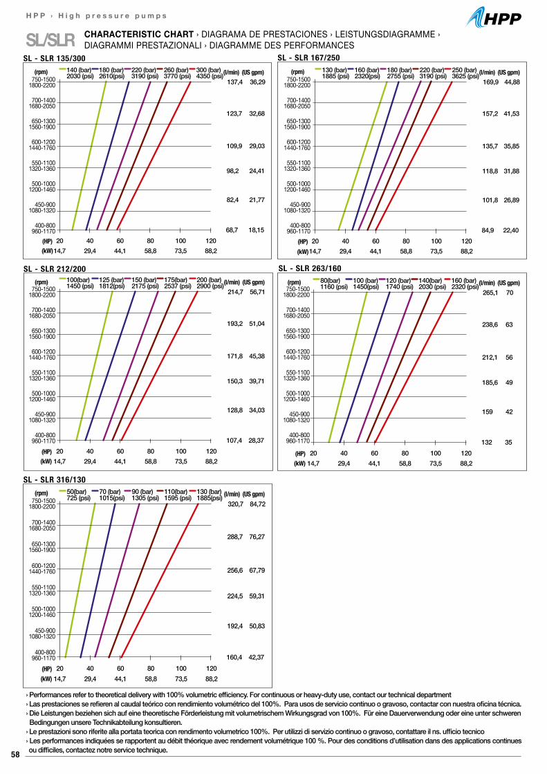
58
H P P › H i g h p r e s s u r e p u m p s
SL/SLR CHARACTERISTIC CHART › DIAGRAMA DE PRESTACIONES › LEISTUNGSDIAGRAMME ›DIAGRAMMI PRESTAZIONALI › DIAGRAMME DES PERFORMANCES
SL - SLR 135/300 SL - SLR 167/250
SL - SLR 212/200
214,7 56,71
20 40 60 80 100 12014,7 29,4 44,1 58,8 73,5 88,2
(HP)(kW)
100(bar)1450 (psi)
125 (bar)1812(psi)
150 (bar)2175 (psi)
175(bar)2537 (psi)
200 (bar)2900 (psi)(l/min) (US gpm)
193,2 51,04
171,8 45,38
150,3 39,71
128,8 34,03
107,4 28,37
(rpm)
SL - SLR 263/160
265,1 70
20 40 60 80 100 12014,7 29,4 44,1 58,8 73,5 88,2
(HP)(kW)
80(bar)1160 (psi)
100 (bar)1450(psi)
120 (bar)1740 (psi)
140(bar)2030 (psi)
160 (bar)2320 (psi)(l/min) (US gpm)
238,6 63
212,1 56
185,6 49
159 42
132 35
(rpm)
SL - SLR 316/130
320,7 84,72
20 40 60 80 100 12014,7 29,4 44,1 58,8 73,5 88,2
(HP)(kW)
50(bar)725 (psi)
70 (bar)1015(psi)
90 (bar)1305 (psi)
110(bar)1595 (psi)
130 (bar)1885(psi) (l/min) (US gpm)
288,7 76,27
256,6 67,79
224,5 59,31
192,4 50,83
160,4 42,37
(rpm)
137,4 36,29
20 40 60 80 100 12014,7 29,4 44,1 58,8 73,5 88,2
(HP)(kW)
140 (bar)2030 (psi)
180 (bar)2610(psi)
220 (bar)3190 (psi)
260 (bar)3770 (psi)
300 (bar)4350 (psi)(l/min) (US gpm)
123,7 32,68
109,9 29,03
98,2 24,41
82,4 21,77
68,7 18,15
(rpm)750-1500
1800-2200
700-14001680-2050
650-13001560-1900
600-12001440-1760
550-11001320-1360
500-10001200-1460
450-9001080-1320
400-800960-1170
169,9 44,88
20 40 60 80 100 12014,7 29,4 44,1 58,8 73,5 88,2
(HP)(kW)
130 (bar)1885 (psi)
160 (bar)2320(psi)
180 (bar)2755 (psi)
220 (bar)3190 (psi)
250 (bar)3625 (psi)(l/min) (US gpm)
157,2 41,53
135,7 35,85
118,8 31,88
101,8 26,89
84,9 22,40
(rpm)750-1500
1800-2200
700-14001680-2050
650-13001560-1900
600-12001440-1760
550-11001320-1360
500-10001200-1460
450-9001080-1320
400-800960-1170
750-15001800-2200
700-14001680-2050
650-13001560-1900
600-12001440-1760
550-11001320-1360
500-10001200-1460
450-9001080-1320
400-800960-1170
750-15001800-2200
700-14001680-2050
650-13001560-1900
600-12001440-1760
550-11001320-1360
500-10001200-1460
450-9001080-1320
400-800960-1170
750-15001800-2200
700-14001680-2050
650-13001560-1900
600-12001440-1760
550-11001320-1360
500-10001200-1460
450-9001080-1320
400-800960-1170
› Performances refer to theoretical delivery with 100% volumetric efficiency. For continuous or heavy-duty use, contact our technical department› Las prestaciones se refieren al caudal teórico con rendimiento volumétrico del 100%. Para usos de servicio continuo o gravoso, contactar con nuestra oficina técnica.› Die Leistungen beziehen sich auf eine theoretische Förderleistung mit volumetrischem Wirkungsgrad von 100%. Für eine Dauerverwendung oder eine unter schweren Bedingungen unsere Technikabteilung konsultieren.› Le prestazioni sono riferite alla portata teorica con rendimento volumetrico 100%. Per utilizzi di servizio continuo o gravoso, contattare il ns. ufficio tecnico› Les performances indiquées se rapportent au débit théorique avec rendement volumétrique 100 %. Pour des conditions d’utilisation dans des applications continues ou difficiles, contactez notre service technique.
59
H P P › H i g h p r e s s u r e p u m p s
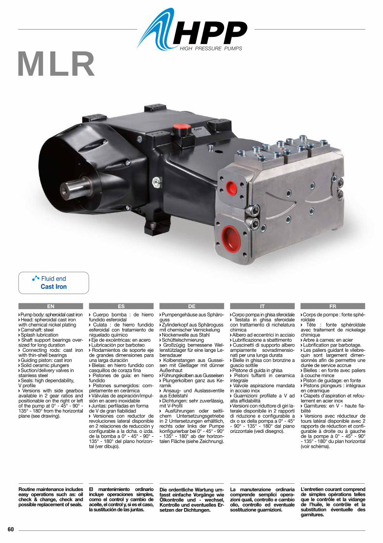
60
MLR
EN ES DE IT FR Corpo pompa in ghisa sferoidale Testata in ghisa sferoidale con trattamento di nichelatura chimica Albero ad eccentrici in acciaio Lubrificazione a sbattimento Cuscinetti di supporto albero ampiamente sovradimensio-nati per una lunga durata Bielle in ghisa con bronzine a guscio sottile Pistone di guida in ghisa Pistoni tuffanti in ceramica integrale Valvole aspirazione mandata in acciaio inox Guarnizioni profilate a V ad alta affidabilità Versioni con riduttore di giri la-terale disponibile in 2 rapporti di riduzione e configurabile a dx o sx della pompa a 0° - 45° - 90° - 135° - 180° dal piano orizzontale (vedi disegno).
La manutenzione ordinaria comprende semplici opera-zioni quali, controllo e cambio olio, controllo ed eventuale sostituzione guarnizioni.
Pump body: spheroidal cast iron Head: spheroidal cast ironwith chemical nickel plating Camshaft: steel Splash lubrication Shaft support bearings over-sized for long duration Connecting rods: cast iron with thin-shell bearings Guiding piston: cast iron Solid ceramic plungers Suction/delivery valves instainless steel Seals: high dependability, V profile Versions with side gearbox available in 2 gear ratios and positionable on the right or left of the pump at 0° - 45° - 90° - 135° - 180° from the horizontal plane (see drawing).
Routine maintenance includes easy operations such as: oil check & change, check and possible replacement of seals.
Cuerpo bomba : de hierro fundido esferoidal Culata : de hierro fundido esferoidal con tratamiento de niquelado químico Eje de excéntricas: en acero Lubricación por barboteo Rodamientos de soporte eje de grandes dimensiones para una larga duración Bielas: en hierro fundido con casquillos de coraza fina Pistones de guía: en hierro fundido Pistones sumergidos: com-pletamente en cerámica Válvulas de aspiración/impul-sión en acero inoxidable Juntas: perfiladas en forma de V de gran fiabilidad Versiones con reductor de revoluciones lateral disponible en 2 relaciones de reducción y configurable a la dcha. o izda. de la bomba a 0° - 45° - 90° - 135° - 180° del plano horizon-tal (ver dibujo).
El mantenimiento ordinario incluye operaciones simples, como el control y cambio de aceite, el control y, si es el caso, la sustitución de las juntas.
Pumpengehäuse aus Sphäro-guss Zylinderkopf aus Sphärogussmit chemischer Vernickelung Nockenwelle aus Stahl Schüttelschmierung Großzügig bemessene Wel-lenstützlager für eine lange Le-bensdauer Kolbenstangen aus Gussei-sen mit Gleitlager mit dünner Außenhaut Führungskolben aus Gusseisen Plungerkolben ganz aus Ke-ramik Ansaug- und Auslassventile aus Edelstahl Dichtungen: sehr zuverlässig, mit V-Profil Ausführungen oder seitli-chem Untersetzungsgetriebe in 2 Untersetzungen erhältlich, rechts oder links der Pumpe konfigurierbar bei 0° - 45° - 90° - 135° - 180° ab der horizon-talen Fläche (siehe Zeichnung).
Die ordentliche Wartung um-fasst einfache Vorgänge wie Ölkontrolle und - wechsel, Kontrolle und eventuelles Er-setzen der Dichtungen.
Corps de pompe : fonte sphé-roïdale Tête : fonte sphéroïdale avec traitement de nickelage chimique Arbre à cames: en acier Lubrification par barbotage. Les paliers guidant le vilebre-quin sont largement dimen-sionnés afin de permettre une durée de service accrue Bielles : en fonte avec paliers à couche mince Piston de guidage: en fonte Pistons plongeurs : intégraux en céramique Clapets d’aspiration et refou-lement en acier inox Garnitures: en V - haute fia-bilité Versions avec réducteur de tours latéral disponible avec 2 rapports de réduction et confi-gurable à droite ou à gauche de la pompe à 0° - 45° - 90° - 135° - 180° du plan horizontal (voir schéma).
L’entretien courant comprend de simples opérations telles que le contrôle et la vidange de l’huile, le contrôle et la substitution éventuelle des garnitures.
Fluid endCast Iron
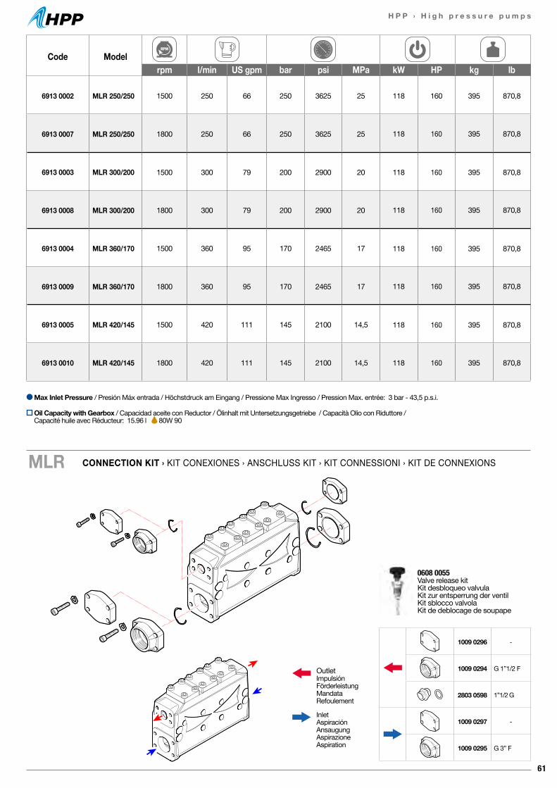
61
H P P › H i g h p r e s s u r e p u m p s
Code Modelrpm l/min US gpm bar psi MPa kW HP kg lb
6913 0002 MLR 250/250 1500 250 66 250 3625 25 118 160 395 870,8
6913 0007 MLR 250/250 1800 250 66 250 3625 25 118 160 395 870,8
6913 0003 MLR 300/200 1500 300 79 200 2900 20 118 160 395 870,8
6913 0008 MLR 300/200 1800 300 79 200 2900 20 118 160 395 870,8
6913 0004 MLR 360/170 1500 360 95 170 2465 17 118 160 395 870,8
6913 0009 MLR 360/170 1800 360 95 170 2465 17 118 160 395 870,8
6913 0005 MLR 420/145 1500 420 111 145 2100 14,5 118 160 395 870,8
6913 0010 MLR 420/145 1800 420 111 145 2100 14,5 118 160 395 870,8
CONNECTION KIT › KIT CONEXIONES › ANSCHLUSS KIT › KIT CONNESSIONI › KIT DE CONNEXIONSMLR
Max Inlet Pressure / Presión Máx entrada / Höchstdruck am Eingang / Pressione Max Ingresso / Pression Max. entrée: 3 bar - 43,5 p.s.i.
0608 0055 Valve release kitKit desbloqueo valvulaKit zur entsperrung der ventilKit sblocco valvolaKit de deblocage de soupape
OutletImpulsiónFörderleistungMandataRefoulement
InletAspiraciónAnsaugungAspirazioneAspiration
1009 0296 -
1009 0294 G 1”1/2 F
2803 0598 1”1/2 G
1009 0297 -
1009 0295 G 3” F
Oil Capacity with Gearbox / Capacidad aceite con Reductor / Ölinhalt mit Untersetzungsgetriebe / Capacità Olio con Riduttore / Capacité huile avec Réducteur: 15.96 l 80W 90
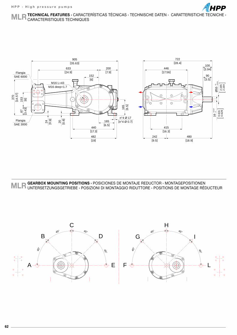
62
H P P › H i g h p r e s s u r e p u m p s
TECHNICAL FEATURES › CARACTERÍSTICAS TÉCNICAS › TECHNISCHE DATEN › CARATTERISTICHE TECNICHE ›CARACTERISTIQUES TECHNIQUESMLR
GEARBOX MOUNTING POSITIONS › POSICIONES DE MONTAJE REDUCTOR › MONTAGEPOSITIONEN UNTERSETZUNGSGETRIEBE › POSIZIONI DI MONTAGGIO RIDUTTORE › POSITIONS DE MONTAGE RÉDUCTEURMLR
100[3.94]
90[3.5]
[28.4]722
[35.63]905
M16 deep=1.7M16 L=43
SAE 6000Flangia
SAE 3000Flangia
[0.9
]24
[ 3.4
3]87
[ 0.8
]20
[ 14.
57]
370
[ 6]
153
[19]482
[17.3]440
[6.5]165 [n°4 Ø 0.7]
n°4 Ø 17
[24.9]633
[7.9]200
[ 6.5
]16
5
[6]152
[17.56]446
[16.3]415
[18.9]480
[9.5]242
16+0
.027
-0
0.63
10.
629
Ø55
+0 -0.0
19
2.16
52.
164
45° 45°
45° 45°
45° 45°
45° 45°
A
B
C
D
E L
I
H
G
F
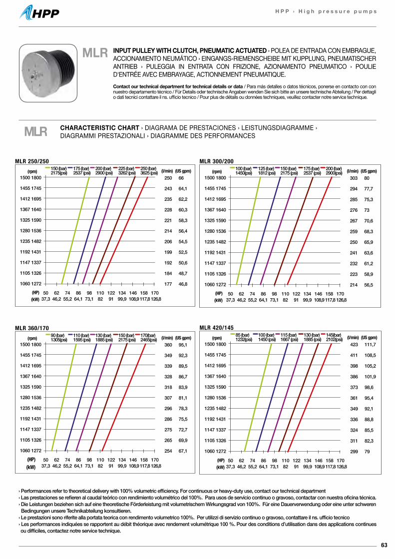
63
H P P › H i g h p r e s s u r e p u m p s
250
243
235
228
221
214
206
199
192
184
177
(l/min)66
64,1
62,2
60,3
58,3
56,4
54,5
52,5
50,6
48,7
46,8
50 62 74 86 98 110 122 134 146 158 17037,3 46,2 55,2 64,1 73,1 82 91 99,9 108,9 117,8 126,8
150 (bar)2175(psi)
175 (bar)2537 (psi)
200 (bar)2900 (psi)
225 (bar)3262 (psi)
250 (bar)3625 (psi) (US gpm)
MLR 250/250
1800
1745
1695
1640
1590
1536
1482
1431
1337
1326
1272
(rpm)1500
1455
1412
1367
1325
1280
1235
1192
1147
1105
1060
(HP)(kW)
303
294
285
276
267
259
250
241
232
223
214
(l/min)80
77,7
75,3
73
70,6
68,3
65,9
63,6
61,2
58,9
56,5
50 62 74 86 98 110 122 134 146 158 17037,3 46,2 55,2 64,1 73,1 82 91 99,9 108,9 117,8 126,8
100 (bar)1450(psi)
125 (bar)1812 (psi)
150 (bar)2175 (psi)
175 (bar)2537 (psi)
200 (bar)2900(psi) (US gpm)
MLR 300/200
1800
1745
1695
1640
1590
1536
1482
1431
1337
1326
1272
(rpm)1500
1455
1412
1367
1325
1280
1235
1192
1147
1105
1060
(HP)(kW)
423
411
398
386
373
361
349
336
324
311
299
(l/min)111,7
108,5
105,2
101,9
98,6
95,4
92,1
88,8
85,5
82,3
79
50 62 74 86 98 110 122 134 146 158 17037,3 46,2 55,2 64,1 73,1 82 91 99,9 108,9 117,8 126,8
85 (bar)1232(psi)
100 (bar)1450 (psi)
115 (bar)1667 (psi)
130 (bar)1885 (psi)
145(bar)2102(psi) (US gpm)
MLR 420/145
1800
1745
1695
1640
1590
1536
1482
1431
1337
1326
1272
(rpm)1500
1455
1412
1367
1325
1280
1235
1192
1147
1105
1060
(HP)(kW)
360
349
339
328
318
307
296
286
275
265
254
(l/min)95,1
92,3
89,5
86,7
83,9
81,1
78,3
75,5
72,7
69,9
67,1
50 62 74 86 98 110 122 134 146 158 17037,3 46,2 55,2 64,1 73,1 82 91 99,9 108,9 117,8 126,8
90 (bar)1305(psi)
110 (bar)1595 (psi)
130 (bar)1885 (psi)
150 (bar)2175 (psi)
170(bar)2465(psi) (US gpm)
MLR 360/170
1800
1745
1695
1640
1590
1536
1482
1431
1337
1326
1272
(rpm)1500
1455
1412
1367
1325
1280
1235
1192
1147
1105
1060
(HP)(kW)
MLR CHARACTERISTIC CHART › DIAGRAMA DE PRESTACIONES › LEISTUNGSDIAGRAMME ›DIAGRAMMI PRESTAZIONALI › DIAGRAMME DES PERFORMANCES
› Performances refer to theoretical delivery with 100% volumetric efficiency. For continuous or heavy-duty use, contact our technical department› Las prestaciones se refieren al caudal teórico con rendimiento volumétrico del 100%. Para usos de servicio continuo o gravoso, contactar con nuestra oficina técnica.› Die Leistungen beziehen sich auf eine theoretische Förderleistung mit volumetrischem Wirkungsgrad von 100%. Für eine Dauerverwendung oder eine unter schweren Bedingungen unsere Technikabteilung konsultieren.› Le prestazioni sono riferite alla portata teorica con rendimento volumetrico 100%. Per utilizzi di servizio continuo o gravoso, contattare il ns. ufficio tecnico› Les performances indiquées se rapportent au débit théorique avec rendement volumétrique 100 %. Pour des conditions d’utilisation dans des applications continues ou difficiles, contactez notre service technique.
MLR INPUT PULLEY WITH CLUTCH, PNEUMATIC ACTUATED › POLEA DE ENTRADA CON EMBRAGUE, ACCIONAMIENTO NEUMÁTICO › EINGANGS-RIEMENSCHEIBE MIT KUPPLUNG, PNEUMATISCHER ANTRIEB › PULEGGIA IN ENTRATA CON FRIZIONE, AZIONAMENTO PNEUMATICO › POULIE D'ENTRÉE AVEC EMBRAYAGE, ACTIONNEMENT PNEUMATIQUE.Contact our technical department for technical details or data / Para más detalles o datos técnicos, ponerse en contacto con con nuestro departamento técnico / Für Details oder technische Angaben wenden Sie sich bitte an unsere technische Abteilung / Per dettagli o dati tecnici contattare il ns. ufficio tecnico / Pour plus de détails ou données techniques, veuillez contacter notre service technique.
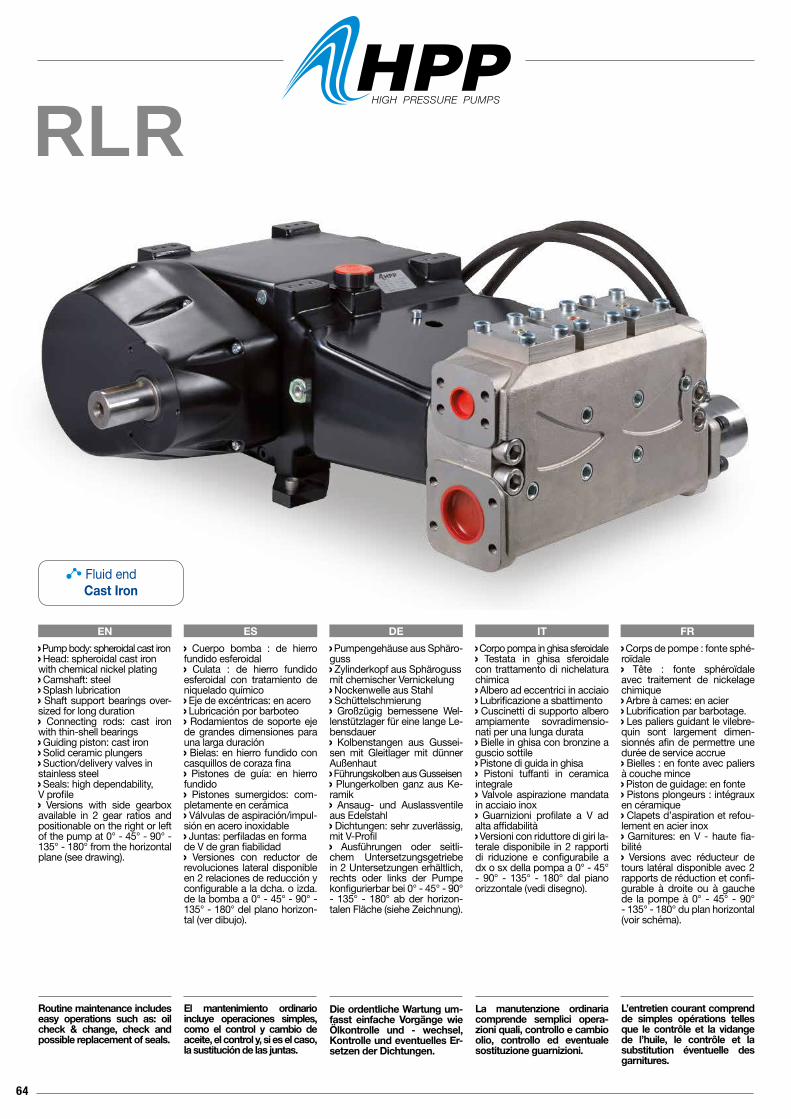
64
RLR
EN ES DE IT FR Corpo pompa in ghisa sferoidale Testata in ghisa sferoidale con trattamento di nichelatura chimica Albero ad eccentrici in acciaio Lubrificazione a sbattimento Cuscinetti di supporto albero ampiamente sovradimensio-nati per una lunga durata Bielle in ghisa con bronzine a guscio sottile Pistone di guida in ghisa Pistoni tuffanti in ceramica integrale Valvole aspirazione mandata in acciaio inox Guarnizioni profilate a V ad alta affidabilità Versioni con riduttore di giri la-terale disponibile in 2 rapporti di riduzione e configurabile a dx o sx della pompa a 0° - 45° - 90° - 135° - 180° dal piano orizzontale (vedi disegno).
La manutenzione ordinaria comprende semplici opera-zioni quali, controllo e cambio olio, controllo ed eventuale sostituzione guarnizioni.
Pump body: spheroidal cast iron Head: spheroidal cast ironwith chemical nickel plating Camshaft: steel Splash lubrication Shaft support bearings over-sized for long duration Connecting rods: cast iron with thin-shell bearings Guiding piston: cast iron Solid ceramic plungers Suction/delivery valves instainless steel Seals: high dependability, V profile Versions with side gearbox available in 2 gear ratios and positionable on the right or left of the pump at 0° - 45° - 90° - 135° - 180° from the horizontal plane (see drawing).
Routine maintenance includes easy operations such as: oil check & change, check and possible replacement of seals.
Cuerpo bomba : de hierro fundido esferoidal Culata : de hierro fundido esferoidal con tratamiento de niquelado químico Eje de excéntricas: en acero Lubricación por barboteo Rodamientos de soporte eje de grandes dimensiones para una larga duración Bielas: en hierro fundido con casquillos de coraza fina Pistones de guía: en hierro fundido Pistones sumergidos: com-pletamente en cerámica Válvulas de aspiración/impul-sión en acero inoxidable Juntas: perfiladas en forma de V de gran fiabilidad Versiones con reductor de revoluciones lateral disponible en 2 relaciones de reducción y configurable a la dcha. o izda. de la bomba a 0° - 45° - 90° - 135° - 180° del plano horizon-tal (ver dibujo).
El mantenimiento ordinario incluye operaciones simples, como el control y cambio de aceite, el control y, si es el caso, la sustitución de las juntas.
Pumpengehäuse aus Sphäro-guss Zylinderkopf aus Sphärogussmit chemischer Vernickelung Nockenwelle aus Stahl Schüttelschmierung Großzügig bemessene Wel-lenstützlager für eine lange Le-bensdauer Kolbenstangen aus Gussei-sen mit Gleitlager mit dünner Außenhaut Führungskolben aus Gusseisen Plungerkolben ganz aus Ke-ramik Ansaug- und Auslassventile aus Edelstahl Dichtungen: sehr zuverlässig, mit V-Profil Ausführungen oder seitli-chem Untersetzungsgetriebe in 2 Untersetzungen erhältlich, rechts oder links der Pumpe konfigurierbar bei 0° - 45° - 90° - 135° - 180° ab der horizon-talen Fläche (siehe Zeichnung).
Die ordentliche Wartung um-fasst einfache Vorgänge wie Ölkontrolle und - wechsel, Kontrolle und eventuelles Er-setzen der Dichtungen.
Corps de pompe : fonte sphé-roïdale Tête : fonte sphéroïdale avec traitement de nickelage chimique Arbre à cames: en acier Lubrification par barbotage. Les paliers guidant le vilebre-quin sont largement dimen-sionnés afin de permettre une durée de service accrue Bielles : en fonte avec paliers à couche mince Piston de guidage: en fonte Pistons plongeurs : intégraux en céramique Clapets d’aspiration et refou-lement en acier inox Garnitures: en V - haute fia-bilité Versions avec réducteur de tours latéral disponible avec 2 rapports de réduction et confi-gurable à droite ou à gauche de la pompe à 0° - 45° - 90° - 135° - 180° du plan horizontal (voir schéma).
L’entretien courant comprend de simples opérations telles que le contrôle et la vidange de l’huile, le contrôle et la substitution éventuelle des garnitures.
Fluid endCast Iron
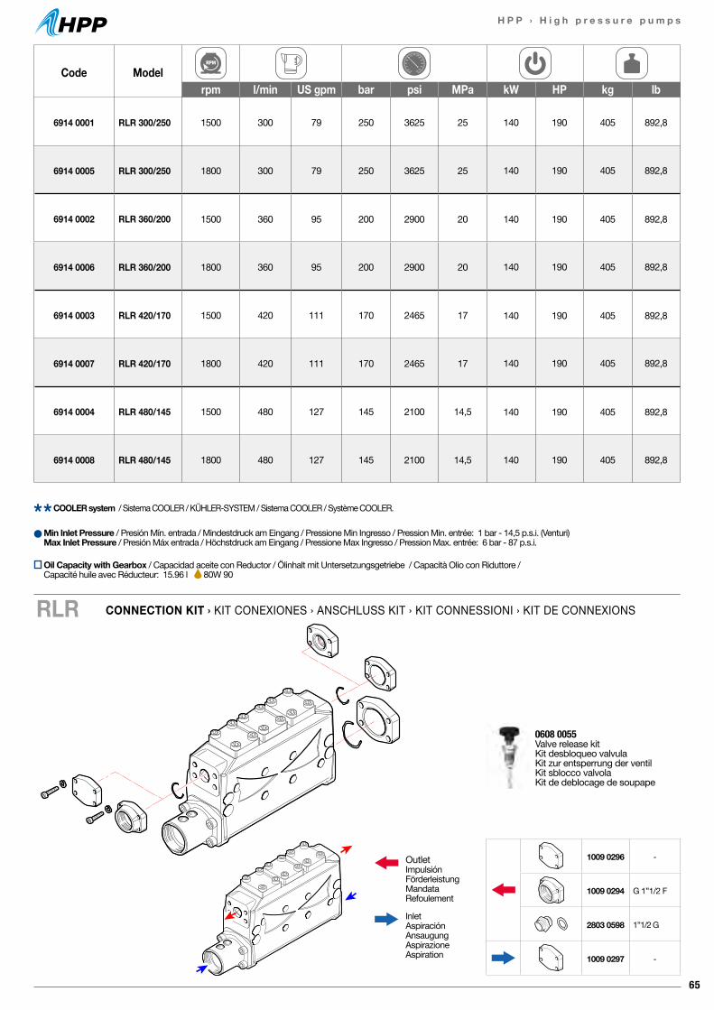
65
H P P › H i g h p r e s s u r e p u m p s
Code Modelrpm l/min US gpm bar psi MPa kW HP kg lb
6914 0001 RLR 300/250 1500 300 79 250 3625 25 140 190 405 892,8
6914 0005 RLR 300/250 1800 300 79 250 3625 25 140 190 405 892,8
6914 0002 RLR 360/200 1500 360 95 200 2900 20 140 190 405 892,8
6914 0006 RLR 360/200 1800 360 95 200 2900 20 140 190 405 892,8
6914 0003 RLR 420/170 1500 420 111 170 2465 17 140 190 405 892,8
6914 0007 RLR 420/170 1800 420 111 170 2465 17 140 190 405 892,8
6914 0004 RLR 480/145 1500 480 127 145 2100 14,5 140 190 405 892,8
6914 0008 RLR 480/145 1800 480 127 145 2100 14,5 140 190 405 892,8
CONNECTION KIT › KIT CONEXIONES › ANSCHLUSS KIT › KIT CONNESSIONI › KIT DE CONNEXIONSRLR
Min Inlet Pressure / Presión Mín. entrada / Mindestdruck am Eingang / Pressione Min Ingresso / Pression Min. entrée: 1 bar - 14,5 p.s.i. (Venturi)Max Inlet Pressure / Presión Máx entrada / Höchstdruck am Eingang / Pressione Max Ingresso / Pression Max. entrée: 6 bar - 87 p.s.i.
COOLER system / Sistema COOLER / KÜHLER-SYSTEM / Sistema COOLER / Système COOLER.
0608 0055 Valve release kitKit desbloqueo valvulaKit zur entsperrung der ventilKit sblocco valvolaKit de deblocage de soupape
OutletImpulsiónFörderleistungMandataRefoulement
InletAspiraciónAnsaugungAspirazioneAspiration
1009 0296 -
1009 0294 G 1”1/2 F
2803 0598 1”1/2 G
1009 0297 -
Oil Capacity with Gearbox / Capacidad aceite con Reductor / Ölinhalt mit Untersetzungsgetriebe / Capacità Olio con Riduttore / Capacité huile avec Réducteur: 15.96 l 80W 90
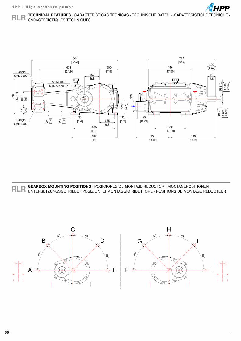
66
H P P › H i g h p r e s s u r e p u m p s
TECHNICAL FEATURES › CARACTERÍSTICAS TÉCNICAS › TECHNISCHE DATEN › CARATTERISTICHE TECNICHE ›CARACTERISTIQUES TECHNIQUESRLR
GEARBOX MOUNTING POSITIONS › POSICIONES DE MONTAJE REDUCTOR › MONTAGEPOSITIONEN UNTERSETZUNGSGETRIEBE › POSIZIONI DI MONTAGGIO RIDUTTORE › POSITIONS DE MONTAGE RÉDUCTEURRLR
100[3.94]
90[3.5]
[28.4]722
[35.6]904
M16 deep=1.7M16 L=43
SAE 6000Flangia
SAE 3000Flangia
[0.9
]24
[ 3.4
3]87
[ 0.8
]20
[ 14.
57]
370
[ 6]
153
[19]482
[17.1]435
[6.5]165[1.4]
36[1.2]31
[24.9]633
[7.9]200
[ 6.5
]16
5
[6]152
[17.56]446
[12.99]330
[18.9]480
[14.09]358
[0.79]20
3"G
16+0
.027
-0
0.63
10.
629
Ø55
+0 -0.0
19
2.16
52.
164
45° 45°
45° 45°
45° 45°
45° 45°
A
B
C
D
E L
I
H
G
F
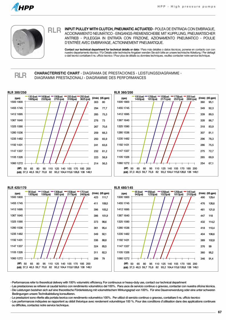
67
H P P › H i g h p r e s s u r e p u m p s
303
294
285
276
267
259
250
241
232
223
214
(l/min)80
77,7
75,3
73
70,6
68,3
65,9
63,6
61,2
58,9
56,5
50 65 80 95 110 125 140 155 170 185 20037,3 48,5 59,7 70,8 82 93,2 104,4115,6 126,8 138 149,1
130 (bar)1885(psi)
160(bar)2320(psi)
190(bar)2755 (psi)
220 (bar)3190(psi)
250 (bar)3625 (psi) (US gpm)
RLR 300/250
1800
1745
1695
1640
1590
1536
1482
1431
1337
1326
1272
(rpm)1500
1455
1412
1367
1325
1280
1235
1192
1147
1105
1060
(HP)(kW)
360
349
339
328
318
307
296
286
275
265
254
(l/min)95,1
92,3
89,5
86,7
83,9
81,1
78,3
75,5
72,7
69,9
67,1
50 65 80 95 110 125 140 155 170 185 20037,3 48,5 59,7 70,8 82 93,2 104,4 115,6 126,8 138 149,1
100 (bar)1450(psi)
125(bar)1812(psi)
150(bar)2175 (psi)
175(bar)2537(psi)
200 bar)2900 (psi) (US gpm)
RLR 360/200
1800
1745
1695
1640
1590
1536
1482
1431
1337
1326
1272
(rpm)1500
1455
1412
1367
1325
1280
1235
1192
1147
1105
1060
(HP)(kW)
423
411
396
386
373
361
349
336
324
311
299
(l/min)111,7
108,5
105,2
101,9
98,6
95,4
92,1
88,8
85,5
82,3
79
50 65 80 95 110 125 140 155 170 185 20037,3 48,5 59,7 70,8 82 93,2 104,4 115,6 126,8 138 149,1
90 (bar)1305(psi)
110bar)1595(psi)
130(bar)1885 (psi)
150(bar)2175(psi)
170 bar)2465(psi) (US gpm)
RLR 420/170
1800
1745
1695
1640
1590
1536
1482
1431
1337
1326
1272
(rpm)1500
1455
1412
1367
1325
1280
1235
1192
1147
1105
1060
(HP)(kW)
490
476
461
447
432
418
404
389
376
360
346
(l/min)129,4
126,6
121,8
118
114,2
110,4
106,6
102,8
99
95,2
91,4
50 65 80 95 110 125 140 155 170 185 20037,3 48,5 59,7 70,8 82 93,2 104,4115,6 126,8 138 149,1
65 (bar)942(psi)
85(bar)1232(psi)
105(bar)1522(psi)
125(bar)1812(psi)
145 bar)2102(psi) (US gpm)
RLR 480/145
1800
1745
1695
1640
1590
1536
1482
1431
1337
1326
1272
(rpm)1500
1455
1412
1367
1325
1280
1235
1192
1147
1105
1060
(HP)(kW)
› Performances refer to theoretical delivery with 100% volumetric efficiency. For continuous or heavy-duty use, contact our technical department› Las prestaciones se refieren al caudal teórico con rendimiento volumétrico del 100%. Para usos de servicio continuo o gravoso, contactar con nuestra oficina técnica.› Die Leistungen beziehen sich auf eine theoretische Förderleistung mit volumetrischem Wirkungsgrad von 100%. Für eine Dauerverwendung oder eine unter schweren Bedingungen unsere Technikabteilung konsultieren.› Le prestazioni sono riferite alla portata teorica con rendimento volumetrico 100%. Per utilizzi di servizio continuo o gravoso, contattare il ns. ufficio tecnico› Les performances indiquées se rapportent au débit théorique avec rendement volumétrique 100 %. Pour des conditions d’utilisation dans des applications continues ou difficiles, contactez notre service technique.
RLR CHARACTERISTIC CHART › DIAGRAMA DE PRESTACIONES › LEISTUNGSDIAGRAMME ›DIAGRAMMI PRESTAZIONALI › DIAGRAMME DES PERFORMANCES
RLR INPUT PULLEY WITH CLUTCH, PNEUMATIC ACTUATED › POLEA DE ENTRADA CON EMBRAGUE, ACCIONAMIENTO NEUMÁTICO › EINGANGS-RIEMENSCHEIBE MIT KUPPLUNG, PNEUMATISCHER ANTRIEB › PULEGGIA IN ENTRATA CON FRIZIONE, AZIONAMENTO PNEUMATICO › POULIE D'ENTRÉE AVEC EMBRAYAGE, ACTIONNEMENT PNEUMATIQUE.Contact our technical department for technical details or data / Para más detalles o datos técnicos, ponerse en contacto con con nuestro departamento técnico / Für Details oder technische Angaben wenden Sie sich bitte an unsere technische Abteilung / Per dettagli o dati tecnici contattare il ns. ufficio tecnico / Pour plus de détails ou données techniques, veuillez contacter notre service technique.

68
69
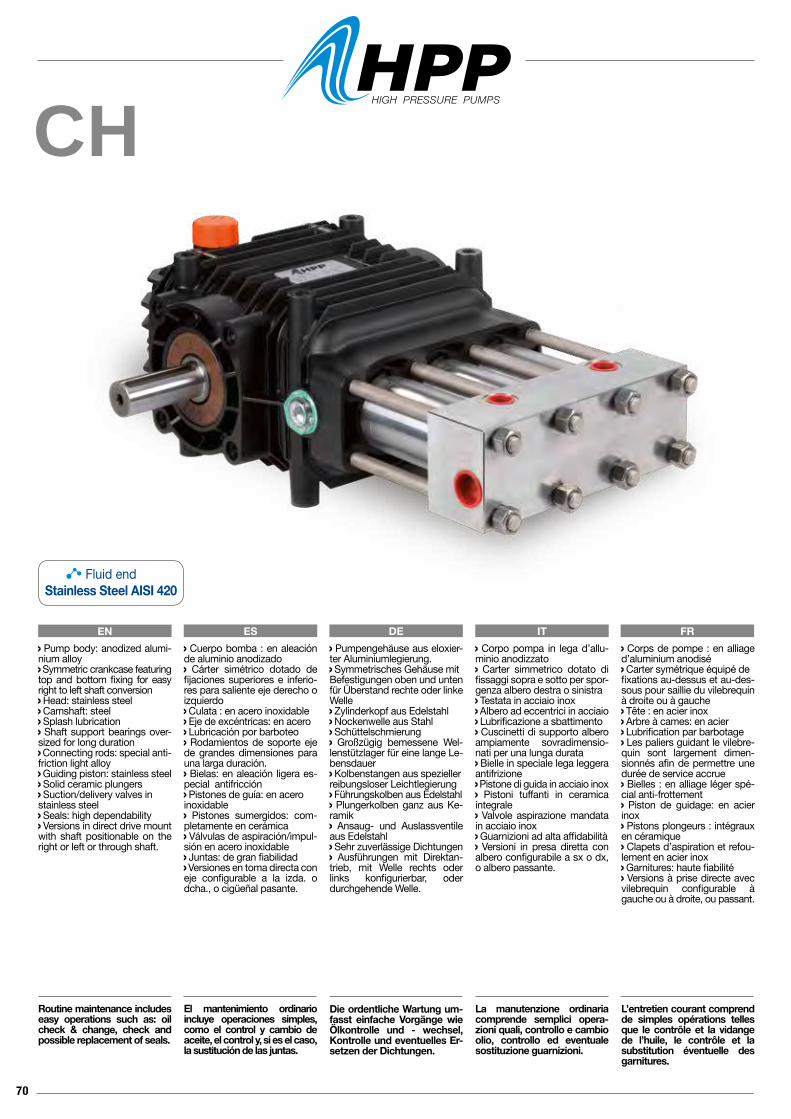
70
CH
EN ES DE IT FR Corpo pompa in lega d’allu-minio anodizzato Carter simmetrico dotato di fissaggi sopra e sotto per spor-genza albero destra o sinistra Testata in acciaio inox Albero ad eccentrici in acciaio Lubrificazione a sbattimento Cuscinetti di supporto albero ampiamente sovradimensio-nati per una lunga durata Bielle in speciale lega leggera antifrizione Pistone di guida in acciaio inox Pistoni tuffanti in ceramica integrale Valvole aspirazione mandata in acciaio inox Guarnizioni ad alta affidabilità Versioni in presa diretta con albero configurabile a sx o dx, o albero passante.
La manutenzione ordinaria comprende semplici opera-zioni quali, controllo e cambio olio, controllo ed eventuale sostituzione guarnizioni.
Pump body: anodized alumi-nium alloy Symmetric crankcase featuring top and bottom fixing for easy right to left shaft conversion Head: stainless steel Camshaft: steel Splash lubrication Shaft support bearings over-sized for long duration Connecting rods: special anti-friction light alloy Guiding piston: stainless steel Solid ceramic plungers Suction/delivery valves instainless steel Seals: high dependability Versions in direct drive mount with shaft positionable on the right or left or through shaft.
Routine maintenance includes easy operations such as: oil check & change, check and possible replacement of seals.
Cuerpo bomba : en aleación de aluminio anodizado Cárter simétrico dotado de fijaciones superiores e inferio-res para saliente eje derecho o izquierdo Culata : en acero inoxidable Eje de excéntricas: en acero Lubricación por barboteo Rodamientos de soporte eje de grandes dimensiones para una larga duración. Bielas: en aleación ligera es-pecial antifricción Pistones de guía: en aceroinoxidable Pistones sumergidos: com-pletamente en cerámica Válvulas de aspiración/impul-sión en acero inoxidable Juntas: de gran fiabilidad Versiones en toma directa coneje configurable a la izda. o dcha., o cigüeñal pasante.
El mantenimiento ordinario incluye operaciones simples, como el control y cambio de aceite, el control y, si es el caso, la sustitución de las juntas.
Pumpengehäuse aus eloxier-ter Aluminiumlegierung. Symmetrisches Gehäuse mitBefestigungen oben und unten für Überstand rechte oder linke Welle Zylinderkopf aus Edelstahl Nockenwelle aus Stahl Schüttelschmierung Großzügig bemessene Wel-lenstützlager für eine lange Le-bensdauer Kolbenstangen aus spezieller reibungsloser Leichtlegierung Führungskolben aus Edelstahl Plungerkolben ganz aus Ke-ramik Ansaug- und Auslassventile aus Edelstahl Sehr zuverlässige Dichtungen Ausführungen mit Direktan-trieb, mit Welle rechts oder links konfigurierbar, oder durchgehende Welle.
Die ordentliche Wartung um-fasst einfache Vorgänge wie Ölkontrolle und - wechsel, Kontrolle und eventuelles Er-setzen der Dichtungen.
Corps de pompe : en alliage d’aluminium anodisé Carter symétrique équipé defixations au-dessus et au-des-sous pour saillie du vilebrequin à droite ou à gauche Tête : en acier inox Arbre à cames: en acier Lubrification par barbotage Les paliers guidant le vilebre-quin sont largement dimen-sionnés afin de permettre une durée de service accrue Bielles : en alliage léger spé-cial anti-frottement Piston de guidage: en acier inox Pistons plongeurs : intégraux en céramique Clapets d’aspiration et refou-lement en acier inox Garnitures: haute fiabilité Versions à prise directe avec vilebrequin configurable à gauche ou à droite, ou passant.
L’entretien courant comprend de simples opérations telles que le contrôle et la vidange de l’huile, le contrôle et la substitution éventuelle des garnitures.
Fluid endStainless Steel AISI 420
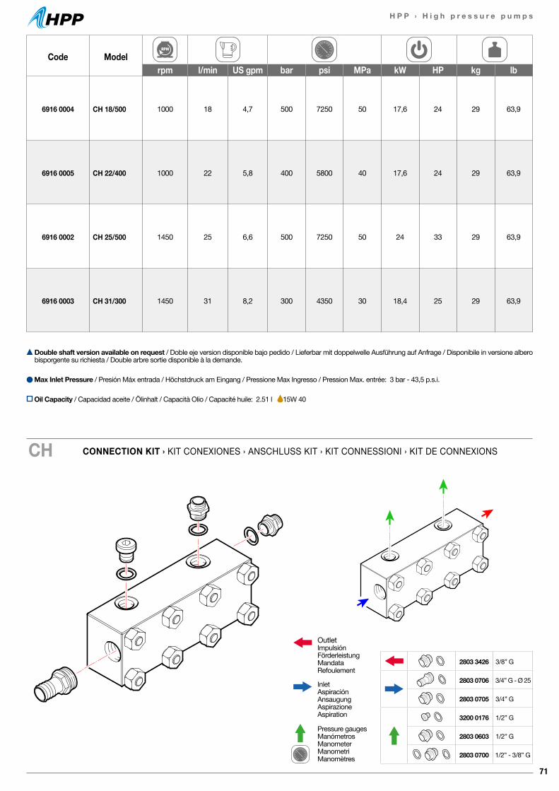
71
H P P › H i g h p r e s s u r e p u m p s
Code Modelrpm l/min US gpm bar psi MPa kW HP kg lb
6916 0004 CH 18/500 1000 18 4,7 500 7250 50 17,6 24 29 63,9
6916 0005 CH 22/400 1000 22 5,8 400 5800 40 17,6 24 29 63,9
6916 0002 CH 25/500 1450 25 6,6 500 7250 50 24 33 29 63,9
6916 0003 CH 31/300 1450 31 8,2 300 4350 30 18,4 25 29 63,9
CONNECTION KIT › KIT CONEXIONES › ANSCHLUSS KIT › KIT CONNESSIONI › KIT DE CONNEXIONSCH
Double shaft version available on request / Doble eje version disponible bajo pedido / Lieferbar mit doppelwelle Ausführung auf Anfrage / Disponibile in versione albero bisporgente su richiesta / Double arbre sortie disponible à la demande.
Max Inlet Pressure / Presión Máx entrada / Höchstdruck am Eingang / Pressione Max Ingresso / Pression Max. entrée: 3 bar - 43,5 p.s.i.
OutletImpulsiónFörderleistungMandataRefoulement
InletAspiraciónAnsaugungAspirazioneAspiration
Pressure gaugesManómetrosManometerManometriManomètres
2803 3426 3/8” G
2803 0706 3/4” G - Ø 25
2803 0705 3/4” G
3200 0176 1/2” G
2803 0603 1/2” G
2803 0700 1/2” - 3/8” G
Oil Capacity / Capacidad aceite / Ölinhalt / Capacità Olio / Capacité huile: 2.51 l 15W 40
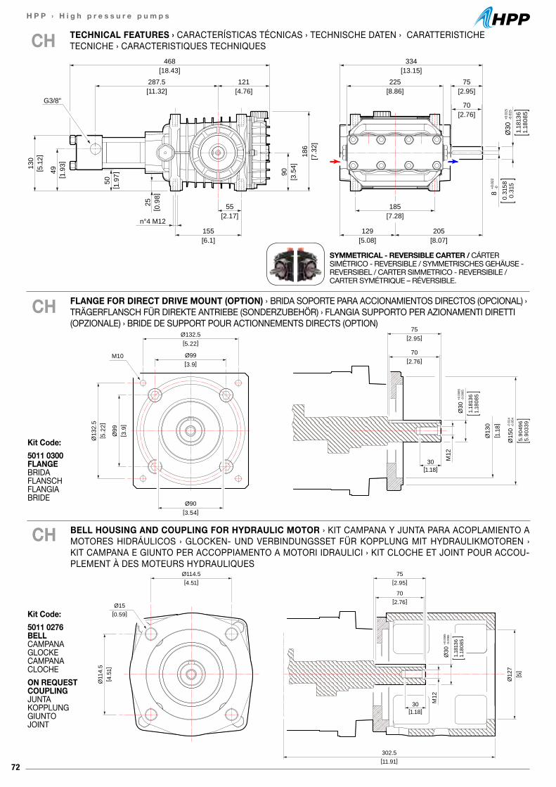
72
H P P › H i g h p r e s s u r e p u m p s
[2.95]75
[2.76]70
[8.07]205
[5.08]129
[7.28]185
[18.43]468
[13.15]334
[11.32]287.5
[8.86]225
[4.76]121
[2.17]55
[6.1]155
n°4 M12
[3.5
4]90
[7.3
2]18
6
[ 5.1
2]13
0
[ 1.9
3]49
[ 1.9
7]50
[ 0.9
8]25
8+0
.022
-0
0.31
580.
315
Ø30
+0.0
15-0
.015
1.18
136
1.18
085
G3/8"
TECHNICAL FEATURES › CARACTERÍSTICAS TÉCNICAS › TECHNISCHE DATEN › CARATTERISTICHE TECNICHE › CARACTERISTIQUES TECHNIQUESCH
SYMMETRICAL - REVERSIBLE CARTER / CÁRTER SIMÉTRICO - REVERSIBLE / SYMMETRISCHES GEHÄUSE - REVERSIBEL / CARTER SIMMETRICO - REVERSIBILE / CARTER SYMÉTRIQUE – RÉVERSIBLE.
75[2.95]
Ø114.5[4.51]
302.5 [11.91]
Ø11
4.5
[ 4.5
1]
Ø15[0.59]
70[2.76]
30[1.18]
M12
Ø30
+0.0
065
-0.0
065
1.18
136
1.18
085
[ 5]
Ø12
7
75[2.95]Ø132.5
[5.22]
Ø99[3.9]
Ø90[3.54]
[ 1.1
8]
Ø13
2.5
[ 5.2
2]
Ø99
[ 3.9
]
70[2.76]
30[1.18]
M12
M10
Ø30
+0.0
065
-0.0
065
1.18
136
1.18
085
Ø15
0-0
.014
-0.0
54
5.90
496
5.90
339
Ø13
0
BELL HOUSING AND COUPLING FOR HYDRAULIC MOTOR › KIT CAMPANA Y JUNTA PARA ACOPLAMIENTO A MOTORES HIDRÁULICOS › GLOCKEN- UND VERBINDUNGSSET FÜR KOPPLUNG MIT HYDRAULIKMOTOREN › KIT CAMPANA E GIUNTO PER ACCOPPIAMENTO A MOTORI IDRAULICI › KIT CLOCHE ET JOINT POUR ACCOU-PLEMENT À DES MOTEURS HYDRAULIQUES
CH
CH FLANGE FOR DIRECT DRIVE MOUNT (OPTION) › BRIDA SOPORTE PARA ACCIONAMIENTOS DIRECTOS (OPCIONAL) › TRÄGERFLANSCH FÜR DIREKTE ANTRIEBE (SONDERZUBEHÖR) › FLANGIA SUPPORTO PER AZIONAMENTI DIRETTI (OPZIONALE) › BRIDE DE SUPPORT POUR ACTIONNEMENTS DIRECTS (OPTION)
Kit Code:5011 0276 BELLCAMPANAGLOCKECAMPANACLOCHEON REQUEST COUPLINGJUNTAKOPPLUNG GIUNTOJOINT
Kit Code:5011 0300 FLANGE BRIDAFLANSCHFLANGIABRIDE
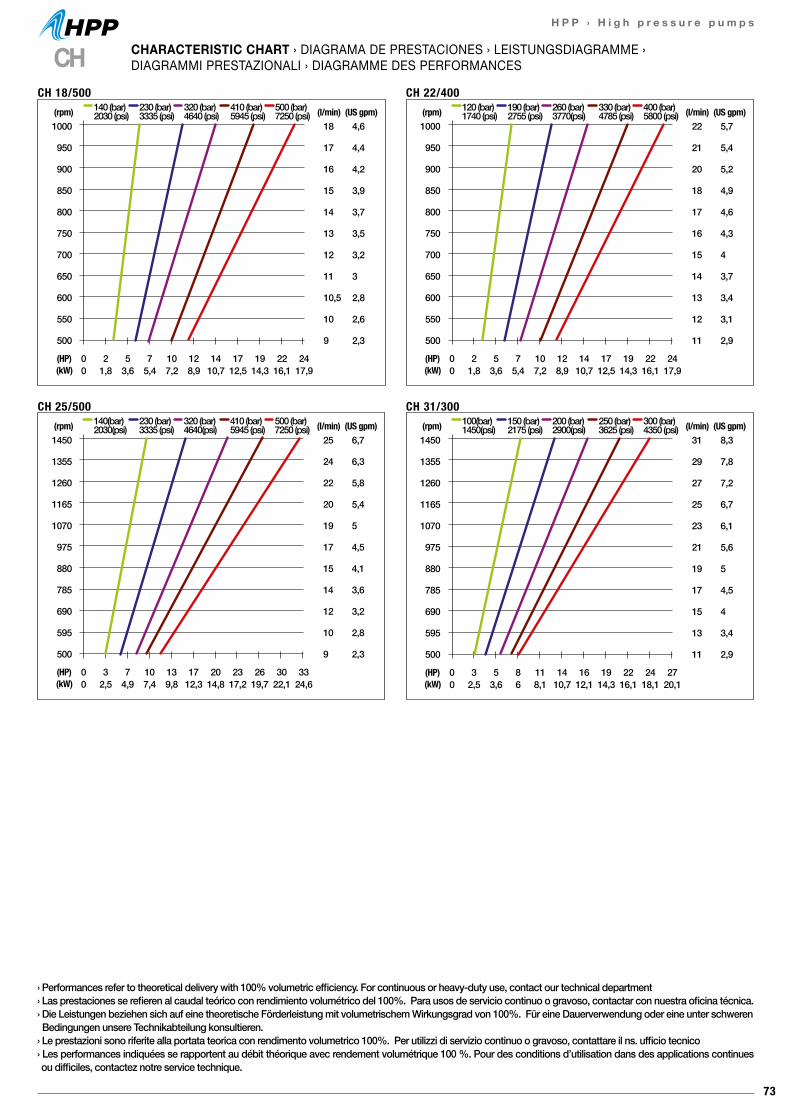
73
H P P › H i g h p r e s s u r e p u m p s
1000
950
900
850
800
750
700
650
600
550
500
18
17
16
15
14
13
12
11
10,5
10
9
(l/min)4,6
4,4
4,2
3,9
3,7
3,5
3,2
3
2,8
2,6
2,3
0 2 5 7 10 12 14 17 19 22 240 1,8 3,6 5,4 7,2 8,9 10,7 12,5 14,3 16,1 17,9
(HP)(kW)
(rpm) 140 (bar)2030 (psi)
230 (bar)3335 (psi)
320 (bar)4640 (psi)
410 (bar)5945 (psi)
500 (bar)7250 (psi) (US gpm)
CH 18/500
1000
950
900
850
800
750
700
650
600
550
500
22
21
20
18
17
16
15
14
13
12
11
(l/min)5,7
5,4
5,2
4,9
4,6
4,3
4
3,7
3,4
3,1
2,9
0 2 5 7 10 12 14 17 19 22 240 1,8 3,6 5,4 7,2 8,9 10,7 12,5 14,3 16,1 17,9
(HP)(kW)
(rpm) 120 (bar)1740 (psi)
190 (bar)2755 (psi)
260 (bar)3770(psi)
330 (bar)4785 (psi)
400 (bar)5800 (psi) (US gpm)
CH 22/400
1450
1355
1260
1165
1070
975
880
785
690
595
500
25
24
22
20
19
17
15
14
12
10
9
(l/min)6,7
6,3
5,8
5,4
5
4,5
4,1
3,6
3,2
2,8
2,3
0 3 7 10 13 17 20 23 26 30 330 2,5 4,9 7,4 9,8 12,3 14,8 17,2 19,7 22,1 24,6
(HP)(kW)
(rpm) 140(bar)2030(psi)
230 (bar)3335 (psi)
320 (bar)4640(psi)
410 (bar)5945 (psi)
500 (bar)7250 (psi) (US gpm)
CH 25/500
1450
1355
1260
1165
1070
975
880
785
690
595
500
31
29
27
25
23
21
19
17
15
13
11
(l/min)8,3
7,8
7,2
6,7
6,1
5,6
5
4,5
4
3,4
2,9
0 3 5 8 11 14 16 19 22 24 270 2,5 3,6 6 8,1 10,7 12,1 14,3 16,1 18,1 20,1
(HP)(kW)
(rpm) 100(bar)1450(psi)
150 (bar)2175 (psi)
200 (bar)2900(psi)
250 (bar)3625 (psi)
300 (bar)4350 (psi) (US gpm)
CH 31/300
CH CHARACTERISTIC CHART › DIAGRAMA DE PRESTACIONES › LEISTUNGSDIAGRAMME ›DIAGRAMMI PRESTAZIONALI › DIAGRAMME DES PERFORMANCES
› Performances refer to theoretical delivery with 100% volumetric efficiency. For continuous or heavy-duty use, contact our technical department› Las prestaciones se refieren al caudal teórico con rendimiento volumétrico del 100%. Para usos de servicio continuo o gravoso, contactar con nuestra oficina técnica.› Die Leistungen beziehen sich auf eine theoretische Förderleistung mit volumetrischem Wirkungsgrad von 100%. Für eine Dauerverwendung oder eine unter schweren Bedingungen unsere Technikabteilung konsultieren.› Le prestazioni sono riferite alla portata teorica con rendimento volumetrico 100%. Per utilizzi di servizio continuo o gravoso, contattare il ns. ufficio tecnico› Les performances indiquées se rapportent au débit théorique avec rendement volumétrique 100 %. Pour des conditions d’utilisation dans des applications continues ou difficiles, contactez notre service technique.
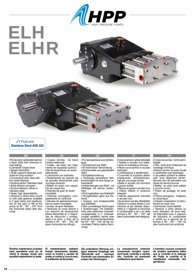
74
ELHELHR
EN ES DE IT FR Corpo pompa in ghisa sferoidale Testata in acciaio con tratta-mento di nichelatura chimica Albero ad eccentrici in acciaio stampato Lubrificazione a sbattimento Cuscinetti di supporto albero ampiamente sovradimensio-nati per una lunga durata Bielle in acciaio con bronzine a guscio sottile Pistone di guida in acciaio inox Pistoni tuffanti in ceramica integrale Valvole aspirazione mandata in acciaio inox Guarnizioni ad alta affidabilità Versioni in presa diretta o con riduttore di giri laterale dispo-nibile in 2 rapporti di riduzione e configurabile a dx o sx della pompa a 30° - 90° - 150° dal piano orizzontale (vedi disegno).
La manutenzione ordinaria comprende semplici opera-zioni quali, controllo e cambio olio, controllo ed eventuale sostituzione guarnizioni.
Pump body: spheroidal cast iron Head: steel with chemical ni-ckel plating Camshaft: forged steel Splash lubrication Shaft support bearings over-sized for long duration Connecting rods: steel withthin-shell bearings Guiding piston: stainless steel Solid ceramic plungers Suction/delivery valves instainless steel Seals: high dependability Versions in direct drive mount or with side gearbox available in 2 gear ratios and positiona-ble on the right or left of the pump at 30° - 90° - 150° from the horizontal plane (see dra-wing).
Routine maintenance includes easy operations such as: oil check & change, check and possible replacement of seals.
Cuerpo bomba : de hierro fundido esferoidal Culata : de acero con trata-miento de niquelado químico Eje de excéntricas: en aceroestampado Lubricación por barboteo Rodamientos de soporte eje de grandes dimensiones para una larga duración Bielas: en acero con casqui-llos de coraza fina Pistones de guía: en aceroinoxidable Pistones sumergidos: com-pletamente en cerámica Válvulas de aspiración/impul-sión en acero inoxidable Juntas: de gran fiabilidad Versiones en toma directa o con reductor de revoluciones lateral disponible en 2 relacio-nes de reducción y configu-rable a la dcha. o izda. de la bomba a 30° - 90° - 150° del plano horizontal (ver dibujo).
El mantenimiento ordinario incluye operaciones simples, como el control y cambio de aceite, el control y, si es el caso, la sustitución de las juntas.
Pumpengehäuse aus Sphäro-guss Zylinderkopf aus Stahlmit chemischer Vernickelung Nockenwelle aus gepresstem Stahl Schüttelschmierung Großzügig bemessene Wel-lenstützlager für eine lange Le-bensdauer Kolbenstangen aus Stahl mit Gleitlager mit dünner Außen-haut Führungskolben aus Edelstahl Plungerkolben ganz aus Ke-ramik Ansaug- und Auslassventile aus Edelstahl Sehr zuverlässige Dichtungen Ausführungen mit Direktan-trieb oder seitlichem Unterset-zungsgetriebe in 2 Unterset-zungen erhältlich, rechts oder links der Pumpe konfigurierbarbei 30° - 90° - 150° ab der ho-rizontalen Fläche (siehe Zeich-nung).
Die ordentliche Wartung um-fasst einfache Vorgänge wie Ölkontrolle und - wechsel, Kontrolle und eventuelles Er-setzen der Dichtungen.
Corps de pompe : fonte sphé-roïdale Tête : acier avec traitement de nickelage chimique Arbre à cames: en acier moulé Lubrification par barbotage Les paliers guidant le vilebre-quin sont largement dimen-sionnés afin de permettre une durée de service accrue Bielles : en acier avec paliers à couche mince Piston de guidage: en acier inox Pistons plongeurs : intégraux en céramique Clapets d’aspiration et refou-lement en acier inox Garnitures: haute fiabilité Versions à prise directe ou avec réducteur de tours laté-ral disponible avec 2 rapports de réduction et configurable à droite ou à gauche de la pompe à 30° - 90° - 150° du plan horizontal (voir schéma).
L’entretien courant comprend de simples opérations telles que le contrôle et la vidange de l’huile, le contrôle et la substitution éventuelle des garnitures.
Fluid endStainless Steel AISI 420
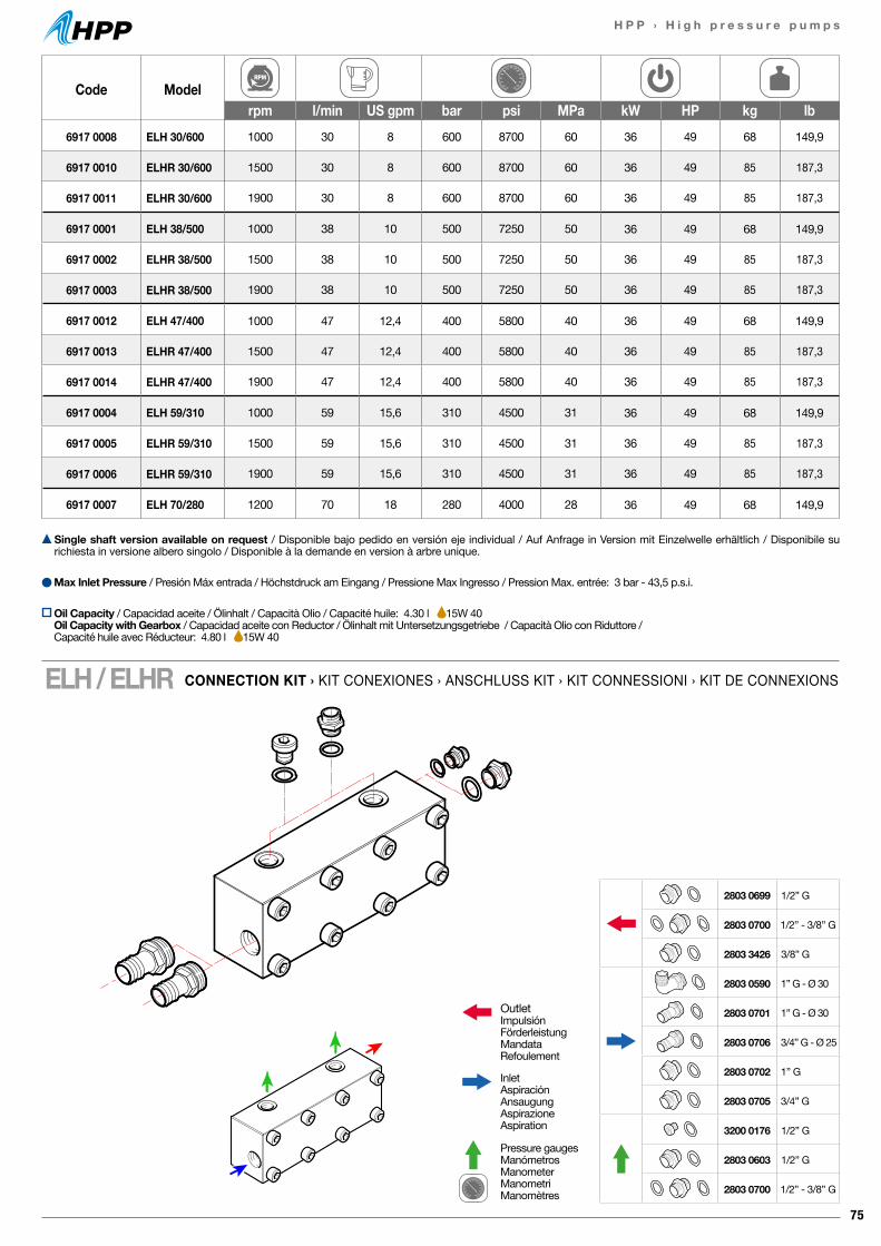
75
H P P › H i g h p r e s s u r e p u m p s
Code Modelrpm l/min US gpm bar psi MPa kW HP kg lb
6917 0008 ELH 30/600 1000 30 8 600 8700 60 36 49 68 149,9
6917 0010 ELHR 30/600 1500 30 8 600 8700 60 36 49 85 187,3
6917 0011 ELHR 30/600 1900 30 8 600 8700 60 36 49 85 187,3
6917 0001 ELH 38/500 1000 38 10 500 7250 50 36 49 68 149,9
6917 0002 ELHR 38/500 1500 38 10 500 7250 50 36 49 85 187,3
6917 0003 ELHR 38/500 1900 38 10 500 7250 50 36 49 85 187,3
6917 0012 ELH 47/400 1000 47 12,4 400 5800 40 36 49 68 149,9
6917 0013 ELHR 47/400 1500 47 12,4 400 5800 40 36 49 85 187,3
6917 0014 ELHR 47/400 1900 47 12,4 400 5800 40 36 49 85 187,3
6917 0004 ELH 59/310 1000 59 15,6 310 4500 31 36 49 68 149,9
6917 0005 ELHR 59/310 1500 59 15,6 310 4500 31 36 49 85 187,3
6917 0006 ELHR 59/310 1900 59 15,6 310 4500 31 36 49 85 187,3
6917 0007 ELH 70/280 1200 70 18 280 4000 28 36 49 68 149,9
CONNECTION KIT › KIT CONEXIONES › ANSCHLUSS KIT › KIT CONNESSIONI › KIT DE CONNEXIONSELH / ELHR
Max Inlet Pressure / Presión Máx entrada / Höchstdruck am Eingang / Pressione Max Ingresso / Pression Max. entrée: 3 bar - 43,5 p.s.i.
Single shaft version available on request / Disponible bajo pedido en versión eje individual / Auf Anfrage in Version mit Einzelwelle erhältlich / Disponibile su richiesta in versione albero singolo / Disponible à la demande en version à arbre unique.
OutletImpulsiónFörderleistungMandataRefoulement
InletAspiraciónAnsaugungAspirazioneAspiration
Pressure gaugesManómetrosManometerManometriManomètres
2803 0699 1/2” G
2803 0700 1/2” - 3/8” G
2803 3426 3/8” G
2803 0590 1” G - Ø 30
2803 0701 1” G - Ø 30
2803 0706 3/4” G - Ø 25
2803 0702 1” G
2803 0705 3/4” G
3200 0176 1/2” G
2803 0603 1/2” G
2803 0700 1/2” - 3/8” G
Oil Capacity / Capacidad aceite / Ölinhalt / Capacità Olio / Capacité huile: 4.30 l 15W 40Oil Capacity with Gearbox / Capacidad aceite con Reductor / Ölinhalt mit Untersetzungsgetriebe / Capacità Olio con Riduttore / Capacité huile avec Réducteur: 4.80 l 15W 40
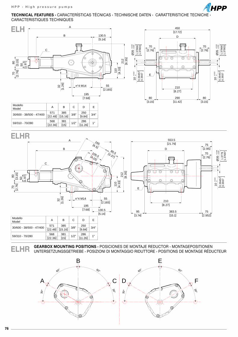
76
H P P › H i g h p r e s s u r e p u m p s
[21.79]553.5
D
[ 2.7
6]70
[ 3.1
5]80
[ 1.9
7]50
[8.27]210
[3.74]95
[15.1]383.5
[7.68]195
C
E
[2.165]55n°4 M14
[5.14]130.5
A
B
32[ 1
.26]
110
[ 4.3
3]21
2[ 8
.35]
ModelloModel A
571 385 3/8” 250 3/4”
B C D E
30/600 - 38/500 - 47/400
568 381 1/2” 286 1”59/310 - 70/280
[22.48] [15.16] [9.84]
[22.36] [15] [11.26]
[2.952]75
10+0
.022
-0
0.39
457
0.39
371.
3776
1.37
697
Ø35
+0.0
09-0
.025
[6.5]
165
[4.15]
105.5[3.37]
85.5[2.95]
75
[2.76]70
[17.72]450
D
[2.76]70
[2.76]70
[ 2.7
6]70
[ 3.1
5]80
[ 1.9
7]50
10+0
.022
-0
0.39
457
0.39
37
10+0
.022
-0
0.39
457
0.39
37
1.37
866
1.37
803
Ø35
+0.0
18-0
.002
1.37
866
1.37
803
Ø35
+0.0
18-0
.002
[8.27]210
[3.15]80
[3.15]80
[11.42]290[7.68]
195
C
E
[2.165]55n°4 M14
[5.14]130.5
A
B
32[ 1
.26]
110
[ 4.3
3]21
2[ 8
.35]
ModelloModel A
571 385 3/8” 250 3/4”
B C D E
30/600 - 38/500 - 47/400
568 381 1/2” 286 1”59/310 - 70/280
[22.48] [15.16] [9.84]
[22.36] [15] [11.26]
60° 60°
30° 30°
A
B
C
60° 60°
30° 30°
D
E
F
GEARBOX MOUNTING POSITIONS › POSICIONES DE MONTAJE REDUCTOR › MONTAGEPOSITIONEN UNTERSETZUNGSGETRIEBE › POSIZIONI DI MONTAGGIO RIDUTTORE › POSITIONS DE MONTAGE RÉDUCTEUR
TECHNICAL FEATURES › CARACTERÍSTICAS TÉCNICAS › TECHNISCHE DATEN › CARATTERISTICHE TECNICHE ›CARACTERISTIQUES TECHNIQUES
ELH
ELHR
ELHR
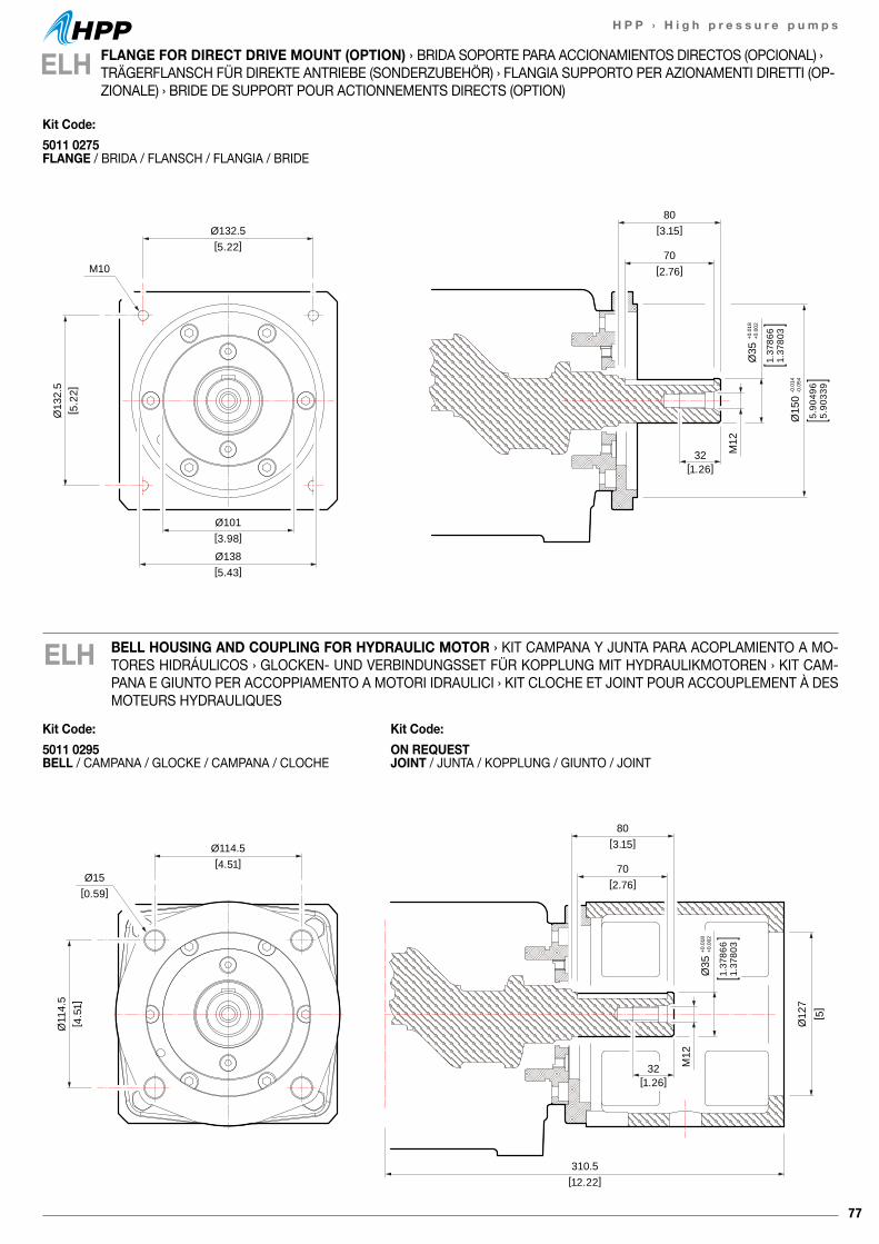
77
H P P › H i g h p r e s s u r e p u m p s
80[3.15]Ø132.5
[5.22]
Ø101[3.98]
Ø138[5.43]
Ø13
2.5
[ 5.2
2]
70[2.76]
32[1.26]
M12
M10
Ø35
+0.0
18+0
.002
1.37
866
1.37
803
Ø15
0-0
.014
-0.0
54
5.90
496
5.90
339
BELL HOUSING AND COUPLING FOR HYDRAULIC MOTOR › KIT CAMPANA Y JUNTA PARA ACOPLAMIENTO A MO-TORES HIDRÁULICOS › GLOCKEN- UND VERBINDUNGSSET FÜR KOPPLUNG MIT HYDRAULIKMOTOREN › KIT CAM-PANA E GIUNTO PER ACCOPPIAMENTO A MOTORI IDRAULICI › KIT CLOCHE ET JOINT POUR ACCOUPLEMENT À DES MOTEURS HYDRAULIQUES
ELH
ELH FLANGE FOR DIRECT DRIVE MOUNT (OPTION) › BRIDA SOPORTE PARA ACCIONAMIENTOS DIRECTOS (OPCIONAL) › TRÄGERFLANSCH FÜR DIREKTE ANTRIEBE (SONDERZUBEHÖR) › FLANGIA SUPPORTO PER AZIONAMENTI DIRETTI (OP-ZIONALE) › BRIDE DE SUPPORT POUR ACTIONNEMENTS DIRECTS (OPTION)
80[3.15]Ø114.5
[4.51]
Ø11
4.5
[ 4.5
1]
70[2.76]
32[1.26]
M12
Ø15
Ø35
+0.0
18+0
.002
1.37
866
1.37
803
[ 5]
Ø12
7
[0.59]
310.5 [12.22]
Kit Code:5011 0295 BELL / CAMPANA / GLOCKE / CAMPANA / CLOCHE
Kit Code:ON REQUEST JOINT / JUNTA / KOPPLUNG / GIUNTO / JOINT
Kit Code:5011 0275 FLANGE / BRIDA / FLANSCH / FLANGIA / BRIDE
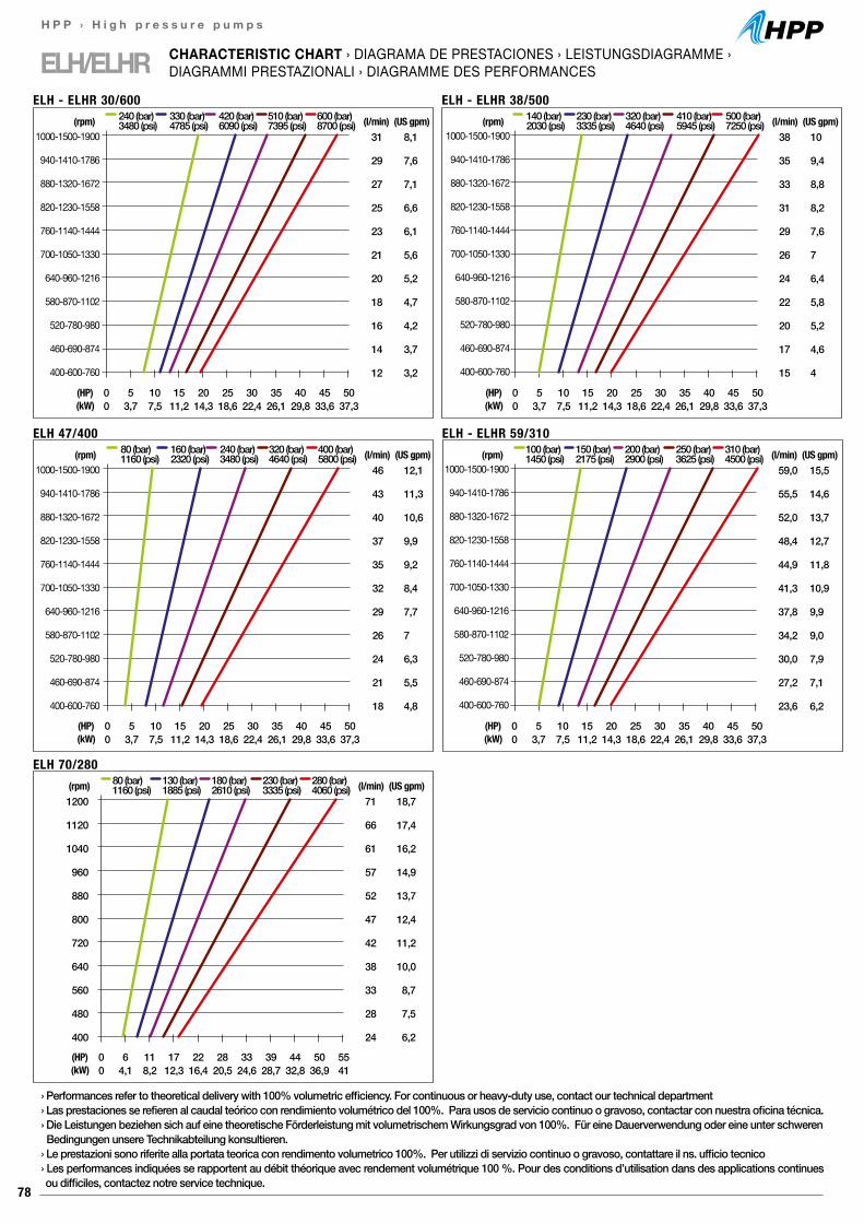
78
H P P › H i g h p r e s s u r e p u m p s
ELH/ELHR CHARACTERISTIC CHART › DIAGRAMA DE PRESTACIONES › LEISTUNGSDIAGRAMME ›DIAGRAMMI PRESTAZIONALI › DIAGRAMME DES PERFORMANCES
1000-1500-1900
940-1410-1786
880-1320-1672
820-1230-1558
760-1140-1444
700-1050-1330
640-960-1216
580-870-1102
520-780-980
460-690-874
400-600-760
38
35
33
31
29
26
24
22
20
17
15
(l/min)10
9,4
8,8
8,2
7,6
7
6,4
5,8
5,2
4,6
4
0 5 10 15 20 25 30 35 40 45 500 3,7 7,5 11,2 14,3 18,6 22,4 26,1 29,8 33,6 37,3
(HP)(kW)
(rpm) 140 (bar)2030 (psi)
230 (bar)3335 (psi)
320 (bar)4640 (psi)
410 (bar)5945 (psi)
500 (bar)7250 (psi) (US gpm)
ELH - ELHR 38/500
1200
1120
1040
960
880
800
720
640
560
480
400
71
66
61
57
52
47
42
38
33
28
24
(l/min)18,7
17,4
16,2
14,9
13,7
12,4
11,2
10,0
8,7
7,5
6,2
0 6 11 17 22 28 33 39 44 50 550 4,1 8,2 12,3 16,4 20,5 24,6 28,7 32,8 36,9 41
(HP)(kW)
(rpm) 80 (bar)1160 (psi)
130 (bar)1885 (psi)
180 (bar)2610 (psi)
230 (bar)3335 (psi)
280 (bar)4060 (psi) (US gpm)
ELH 70/280
1000-1500-1900
940-1410-1786
880-1320-1672
820-1230-1558
760-1140-1444
700-1050-1330
640-960-1216
580-870-1102
520-780-980
460-690-874
400-600-760
31
29
27
25
23
21
20
18
16
14
12
(l/min)8,1
7,6
7,1
6,6
6,1
5,6
5,2
4,7
4,2
3,7
3,2
0 5 10 15 20 25 30 35 40 45 500 3,7 7,5 11,2 14,3 18,6 22,4 26,1 29,8 33,6 37,3
(HP)(kW)
(rpm) 240 (bar)3480 (psi)
330 (bar)4785 (psi)
420 (bar)6090 (psi)
510 (bar)7395 (psi)
600 (bar)8700 (psi) (US gpm)
ELH - ELHR 30/600
1000-1500-1900
940-1410-1786
880-1320-1672
820-1230-1558
760-1140-1444
700-1050-1330
640-960-1216
580-870-1102
520-780-980
460-690-874
400-600-760
46
43
40
37
35
32
29
26
24
21
18
(l/min)12,1
11,3
10,6
9,9
9,2
8,4
7,7
7
6,3
5,5
4,8
0 5 10 15 20 25 30 35 40 45 500 3,7 7,5 11,2 14,3 18,6 22,4 26,1 29,8 33,6 37,3
(HP)(kW)
(rpm) 80 (bar)1160 (psi)
160 (bar)2320 (psi)
240 (bar)3480 (psi)
320 (bar)4640 (psi)
400 (bar)5800 (psi) (US gpm)
ELH 47/400
1000-1500-1900
940-1410-1786
880-1320-1672
820-1230-1558
760-1140-1444
700-1050-1330
640-960-1216
580-870-1102
520-780-980
460-690-874
400-600-760
59,0
55,5
52,0
48,4
44,9
41,3
37,8
34,2
30,0
27,2
23,6
(l/min)15,5
14,6
13,7
12,7
11,8
10,9
9,9
9,0
7,9
7,1
6,2
0 5 10 15 20 25 30 35 40 45 500 3,7 7,5 11,2 14,3 18,6 22,4 26,1 29,8 33,6 37,3
(HP)(kW)
(rpm) 100 (bar)1450 (psi)
150 (bar)2175 (psi)
200 (bar)2900 (psi)
250 (bar)3625 (psi)
310 (bar)4500 (psi) (US gpm)
ELH - ELHR 59/310
› Performances refer to theoretical delivery with 100% volumetric efficiency. For continuous or heavy-duty use, contact our technical department› Las prestaciones se refieren al caudal teórico con rendimiento volumétrico del 100%. Para usos de servicio continuo o gravoso, contactar con nuestra oficina técnica.› Die Leistungen beziehen sich auf eine theoretische Förderleistung mit volumetrischem Wirkungsgrad von 100%. Für eine Dauerverwendung oder eine unter schweren Bedingungen unsere Technikabteilung konsultieren.› Le prestazioni sono riferite alla portata teorica con rendimento volumetrico 100%. Per utilizzi di servizio continuo o gravoso, contattare il ns. ufficio tecnico› Les performances indiquées se rapportent au débit théorique avec rendement volumétrique 100 %. Pour des conditions d’utilisation dans des applications continues ou difficiles, contactez notre service technique.

79
H P P › H i g h p r e s s u r e p u m p s
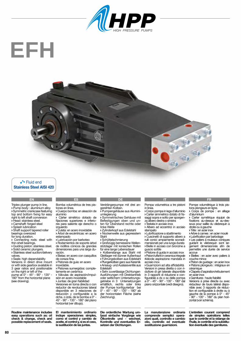
80
EFH
Pompa volumetrica a tre pistoni in linea.› Corpo pompa in lega d’alluminio› Carter simmetrico dotato di fis-saggi sopra e sotto per sporgen-za albero destra o sinistra› Testata in acciaio inox› Albero ad eccentrici in acciaio stampato› Lubrificazione a sbattimento› Cuscinetti di supporto albero a rulli conici ampiamente sovradi-mensionati per una lunga durata› Bielle in acciaio con bronzine a guscio sottile› Pistone di guida in acciaio inox› Pistoni tuffanti in ceramica integrale› Valvole aspirazione mandata in acciaio inox› Guarnizioni ad alta affidabilitàVersioni in presa diretta o con ri-duttore di giri laterale disponibile in 3 rapporti di riduzione e con-figurabile a dx o sx della pompa a 0° - 45° - 90° - 135° - 180° dal piano orizzontale (vedi disegno).
La manutenzione ordinaria comprende semplici opera-zioni quali, controllo e cambio olio, controllo ed eventuale sostituzione guarnizioni.
Pompe volumétrique à trois pis-tons plongeurs en ligne.› Corps de pompe : en alliage d’aluminium› Carter symétrique équipé de fixations au-dessus et au-des-sous pour saillie du vilebrequin à droite ou à gauche› Tête : en acier inox› Arbre à cames : en acier moulé› Lubrification par barbotage› Les paliers à rouleaux coniques guidant le vilebrequin sont lar-gement dimensionnés afin de permettre une durée de service accrue› Bielles : en acier avec paliers à couche mince› Piston de guidage : en acier inox› Pistons plongeurs : intégraux en céramique› Clapets d’aspiration/refoulement en acier inox › Garnitures : haute fiabilitéVersions à prise directe ou avec réducteur de tours latéral dispo-nible avec 3 rapports de réduc-tion et configurable à droite ou à gauche de la pompe à 0° - 45° - 90° - 135° - 180° du plan hori-zontal (voir schéma).
L’entretien courant comprend de simples opérations telles que le contrôle et la vidange de l’huile, le contrôle et la substitu-tion éventuelle des garnitures.
Verdrängerpumpe mit drei an-gereihten Kolben.› Pumpengehäuse aus Alumini-umlegierung› Symmetrisches Gehäuse mit Befestigungen oben und un-ten für Überstand rechte oder linke Welle › Zylinderkopf aus Edelstahl› Nockenwelle aus gepresstem Stahl› Schüttelschmierung› Großzügig bemessene Wellen-stützlager mit konischen Rollen für eine lange Lebensdauer› Kolbenstange aus Stahl mit Gleitlager mit dünner Außenhaut › Führungskolben aus Edelstahl› Plungerkolben ganz aus Keramik› Ansaug- und Auslassventile aus Edelstahl› Sehr zuverlässige DichtungenAusführungen mit Direktantrieb oder seitlichem Untersetzungs-getriebe in 3 Untersetzungen erhältlich, rechts oder links der Pumpe konfigurierbar bei 0° - 45° - 90° - 135° - 180° ab der horizontalen Fläche (siehe Zeichnung).
Die ordentliche Wartung um-fasst einfache Vorgänge wie Ölkontrolle und - wechsel, Kontrolle und eventuelles Er-setzen der Dichtungen.
Bomba volumétrica de tres pis-tones en línea.› Cuerpo bomba: en aleación de aluminio› Cárter simétrico dotado de fijaciones superiores e inferio-res para saliente eje derecho o izquierdo› Culata: en acero inoxidable› Árbol de excéntricas: en acero estampado› Lubricación por barboteo› Rodamientos de soporte árbol de rodillos cónicos de grandes dimensiones para una larga du-ración.› Bielas: en acero con casquillos de coraza fina.› Pistones de guía: en aceroinoxidable.› Pistones sumergidos: comple-tamente en cerámica› Válvulas de aspiración/impul-sión en acero inoxidable› Juntas: de gran fiabilidadVersiones en toma directa o con reductor de revoluciones lateral disponible en 3 relaciones de reducción y configurable a la dcha. o izda. de la bomba a 0° - 45° - 90° - 135° - 180° del plano horizontal (ver dibujo).
El mantenimiento ordinario incluye operaciones simples, como el control y cambio de aceite, el control y, si es el caso, la sustitución de las juntas.
Triplex plunger pump in line.› Pump body : aluminium alloy › Symmetric crankcase featuring top and bottom fixing for easy right to left shaft conversion› Head: stainless steel.› Camshaft: forged steel› Splash lubrication› Shaft support tapered roller bearings oversizedfor long duration.› Connecting rods: steel with thin-shell bearings.› Guiding piston: stainless steel.› Solid ceramic plungers. › Stainless steel suction/delivery valves.› Seals: high dependability Versions in direct drive mount or with side gearbox available in3 gear ratios and positionable on the right or left of the pump at 0° - 45° - 90° - 135° - 180° from the horizontal plane (see drawing).
Routine maintenance includes easy operations such as: oil check & change, check and possible replacement of seals.
EN ES DE IT FR
Fluid endStainless Steel AISI 420
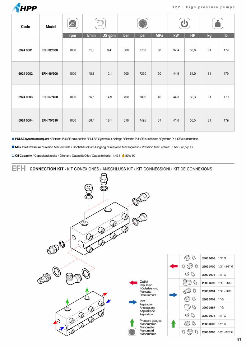
81
H P P › H i g h p r e s s u r e p u m p s
CONNECTION KIT › KIT CONEXIONES › ANSCHLUSS KIT › KIT CONNESSIONI › KIT DE CONNEXIONSEFH
Code Model
rpm l/min US gpm bar psi MPa kW HP kg lb
6924 0001 EFH 32/600 1000 31,8 8,4 600 8700 60 37,4 50,8 81 179
6924 0002 EFH 46/500 1000 45,8 12,1 500 7250 50 44,9 61,0 81 179
6924 0003 EFH 57/400 1000 56,5 14,9 400 5800 40 44,3 60,3 81 179
6924 0004 EFH 70/310 1000 68,4 18,1 310 4495 31 41,6 56,5 81 179
Max Inlet Pressure / Presión Máx entrada / Höchstdruck am Eingang / Pressione Max Ingresso / Pression Max. entrée: 3 bar - 43,5 p.s.i.
PULSE system on request / Sistema PULSE bajo pedido / PULSE-System auf Anfrage / Sistema PULSE su richiesta / Système PULSE à la demande.
OutletImpulsiónFörderleistungMandataRefoulement
InletAspiraciónAnsaugungAspirazioneAspiration
Pressure gaugesManómetrosManometerManometriManomètres
2803 0603 1/2” G
2803 0700 1/2” - 3/8” G
3200 0176 1/2” G
2803 0590 1” G - Ø 30
2803 0701 1” G - Ø 30
2803 0702 1” G
3202 0387 1” G
3200 0176 1/2” G
2803 0603 1/2” G
2803 0700 1/2” - 3/8” G
Oil Capacity / Capacidad aceite / Ölinhalt / Capacità Olio / Capacité huile: 4.43 l 80W 90
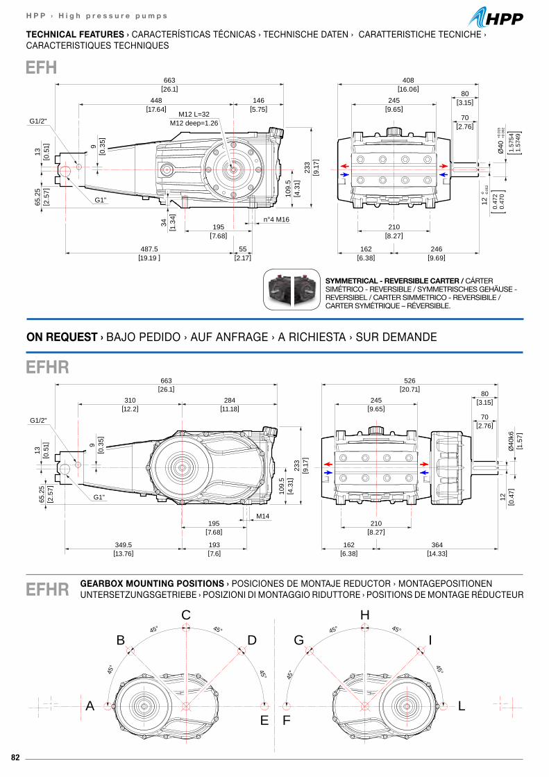
82
H P P › H i g h p r e s s u r e p u m p s
TECHNICAL FEATURES › CARACTERÍSTICAS TÉCNICAS › TECHNISCHE DATEN › CARATTERISTICHE TECNICHE ›CARACTERISTIQUES TECHNIQUES
EFH
SYMMETRICAL - REVERSIBLE CARTER / CÁRTER SIMÉTRICO - REVERSIBLE / SYMMETRISCHES GEHÄUSE - REVERSIBEL / CARTER SIMMETRICO - REVERSIBILE / CARTER SYMÉTRIQUE – RÉVERSIBLE.
663[26.1]
526[20.71]
310[12.2]
284[11.18]
233
[ 9.1
7]
109.
5[ 4
.31]
195[7.68]
349.5[13.76]
193[7.6]
M14
65.2
5[ 2
.57]
13[ 0
.51] 9
[ 0.3
5]
245[9.65]
80[3.15]
70[2.76]
210[8.27]
364[14.33]
162[6.38]
12[ 0
.47]
Ø40
k6[ 1
.57]
G1”
G1/2"
GEARBOX MOUNTING POSITIONS › POSICIONES DE MONTAJE REDUCTOR › MONTAGEPOSITIONEN UNTERSETZUNGSGETRIEBE › POSIZIONI DI MONTAGGIO RIDUTTORE › POSITIONS DE MONTAGE RÉDUCTEUR
ON REQUEST › BAJO PEDIDO › AUF ANFRAGE › A RICHIESTA › SUR DEMANDE
EFHR
EFHR
45° 45°
45° 45°
A
B
C
D
E
45°45°
45°
45°
L
I
H
G
F
663[26.1]
408[16.06]
448[17.64]
146[5.75]
233
[ 9.1
7]
109.
5[ 4
.31]
195[7.68]
487.5[19.19 ]
55[2.17]
n°4 M16
65.2
5[ 2
.57]
13[ 0
.51] 9
[ 0.3
5]245
[9.65]
80[3.15]
70[2.76]
210[8.27]
246[9.69]
162[6.38]
G1”
G1/2"M12 L=32
M12 deep=1.26
Ø40
+0.0
15+0
.002
1.57
541.
5749
0.47
20.
470
12-0 -0
.052
34[ 1
.34]
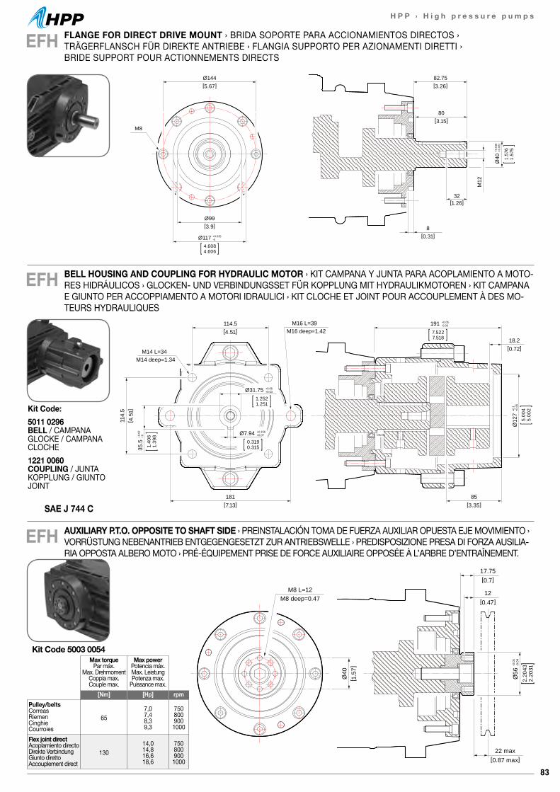
83
H P P › H i g h p r e s s u r e p u m p s
17.75[0.7]
22 max[0.87 max]
12[0.47]
Ø56
-0.0
1-0
.04
2.20
432.
2031
Ø40
[ 1.5
7]
M8 L=12M8 deep=0.47
17.75[0.7]
22 max[0.87 max]
12[0.47]
Ø56
-0.0
1-0
.04
2.20
432.
2031
Ø40
[ 1.5
7]
M8 L=12M8 deep=0.47
EFH
EFH
82.75[3.26]
Ø144[5.67]
Ø99[3.9]
80[3.15]
32[1.26]
8[0.31]
M12
M8
Ø117 +0.035-0
4.6084.606
Ø40
+0.0
18+0
.002
1.57
61.
575
FLANGE FOR DIRECT DRIVE MOUNT › BRIDA SOPORTE PARA ACCIONAMIENTOS DIRECTOS › TRÄGERFLANSCH FÜR DIREKTE ANTRIEBE › FLANGIA SUPPORTO PER AZIONAMENTI DIRETTI › BRIDE SUPPORT POUR ACTIONNEMENTS DIRECTS
BELL HOUSING AND COUPLING FOR HYDRAULIC MOTOR › KIT CAMPANA Y JUNTA PARA ACOPLAMIENTO A MOTO-RES HIDRÁULICOS › GLOCKEN- UND VERBINDUNGSSET FÜR KOPPLUNG MIT HYDRAULIKMOTOREN › KIT CAMPANA E GIUNTO PER ACCOPPIAMENTO A MOTORI IDRAULICI › KIT CLOCHE ET JOINT POUR ACCOUPLEMENT À DES MO-TEURS HYDRAULIQUES
114.5[4.51]
18.2[0.72]
114.
5[ 4
.51]
181[7.13]
85[3.35]
M14 L=34M14 deep=1.34
M16 L=39M16 deep=1.42
191 +0.05-0.05
7.5227.518
Ø31.75 +0.05+0.03
1.2521.251
Ø7.94 +0.156+0.07
0.3190.315
Ø12
7+0
.1+0
.05
5.00
45.
002
35.5
+0.0
2+0
1.40
61.
398
EFH AUXILIARY P.T.O. OPPOSITE TO SHAFT SIDE › PREINSTALACIÓN TOMA DE FUERZA AUXILIAR OPUESTA EJE MOVIMIENTO › VORRÜSTUNG NEBENANTRIEB ENTGEGENGESETZT ZUR ANTRIEBSWELLE › PREDISPOSIZIONE PRESA DI FORZA AUSILIA-RIA OPPOSTA ALBERO MOTO › PRÉ-ÉQUIPEMENT PRISE DE FORCE AUXILIAIRE OPPOSÉE À L’ARBRE D’ENTRAÎNEMENT.
Max torquePar máx.
Max. DrehmomentCoppia max.Couple max.
Max powerPotencia máx.Max. LeistungPotenza max.
Puissance max.[Nm] [Hp] rpm
Pulley/beltsCorreasRiemenCinghieCourroies
657,07,48,39,3
7508009001000
Flex joint directAcoplamiento directoDirekte VerbindungGiunto direttoAccouplement direct
13014,014,816,618,6
7508009001000
Kit Code 5003 0054
SAE J 744 C
Kit Code:5011 0296 BELL / CAMPANAGLOCKE / CAMPANACLOCHE1221 0060 COUPLING / JUNTAKOPPLUNG / GIUNTOJOINT
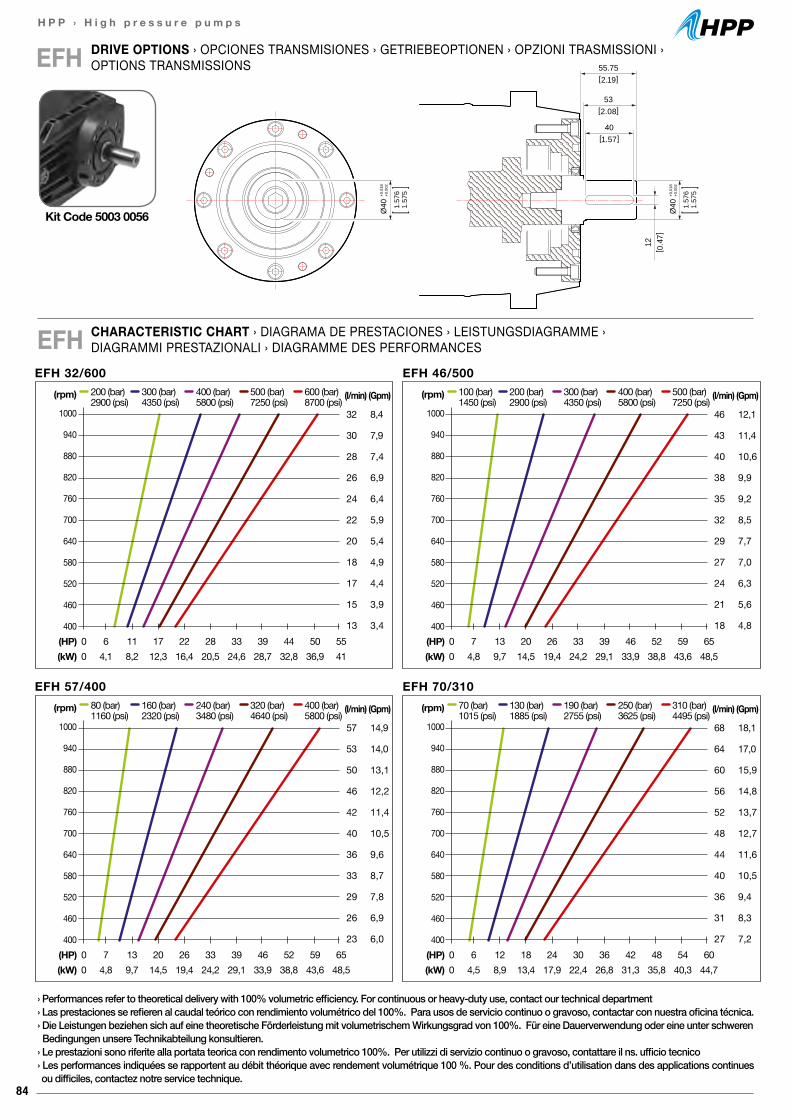
84
H P P › H i g h p r e s s u r e p u m p s
55.75[2.19]
12[ 0
.47]
53[2.08]
40[1.57]
Ø40
+0.0
18+0
.002
1.57
61.
575
Ø40
+0.0
18+0
.002
1.57
61.
575
CHARACTERISTIC CHART › DIAGRAMA DE PRESTACIONES › LEISTUNGSDIAGRAMME ›DIAGRAMMI PRESTAZIONALI › DIAGRAMME DES PERFORMANCESEFH
EFH 32/600(rpm)
1000
940
880
820
760
700
640
580
520
460
400
(l/min)
32
30
28
26
24
22
20
18
17
15
13
(Gpm)
8,4
7,9
7,4
6,9
6,4
5,9
5,4
4,9
4,4
3,9
3,4
200 (bar) 300 (bar) 400 (bar) 500 (bar) 600 (bar)2900 (psi) 4350 (psi) 5800 (psi) 7250 (psi) 8700 (psi)
(HP) 0 6 11 17 22 28 33 39 44 50 55(kW) 0 4,1 8,2 12,3 16,4 20,5 24,6 28,7 32,8 36,9 41
EFH 46/500(rpm)
1000
940
880
820
760
700
640
580
520
460
400
(l/min)
46
43
40
38
35
32
29
27
24
21
18
(Gpm)
12,1
11,4
10,6
9,9
9,2
8,5
7,7
7,0
6,3
5,6
4,8
100 (bar) 200 (bar) 300 (bar) 400 (bar) 500 (bar)1450 (psi) 2900 (psi) 4350 (psi) 5800 (psi) 7250 (psi)
(HP) 0 7 13 20 26 33 39 46 52 59 65(kW) 0 4,8 9,7 14,5 19,4 24,2 29,1 33,9 38,8 43,6 48,5
EFH 57/400(rpm)
1000
940
880
820
760
700
640
580
520
460
400
(l/min)
57
53
50
46
42
40
36
33
29
26
23
(Gpm)
14,9
14,0
13,1
12,2
11,4
10,5
9,6
8,7
7,8
6,9
6,0
80 (bar) 160 (bar) 240 (bar) 320 (bar) 400 (bar)1160 (psi) 2320 (psi) 3480 (psi) 4640 (psi) 5800 (psi)
(HP) 0 7 13 20 26 33 39 46 52 59 65(kW) 0 4,8 9,7 14,5 19,4 24,2 29,1 33,9 38,8 43,6 48,5
EFH 70/310(rpm)
1000
940
880
820
760
700
640
580
520
460
400
(l/min)
68
64
60
56
52
48
44
40
36
31
27
(Gpm)
18,1
17,0
15,9
14,8
13,7
12,7
11,6
10,5
9,4
8,3
7,2
70 (bar) 130 (bar) 190 (bar) 250 (bar) 310 (bar)1015 (psi) 1885 (psi) 2755 (psi) 3625 (psi) 4495 (psi)
(HP) 0 6 12 18 24 30 36 42 48 54 60(kW) 0 4,5 8,9 13,4 17,9 22,4 26,8 31,3 35,8 40,3 44,7
DRIVE OPTIONS › OPCIONES TRANSMISIONES › GETRIEBEOPTIONEN › OPZIONI TRASMISSIONI › OPTIONS TRANSMISSIONSEFH
Kit Code 5003 0056
› Performances refer to theoretical delivery with 100% volumetric efficiency. For continuous or heavy-duty use, contact our technical department› Las prestaciones se refieren al caudal teórico con rendimiento volumétrico del 100%. Para usos de servicio continuo o gravoso, contactar con nuestra oficina técnica.› Die Leistungen beziehen sich auf eine theoretische Förderleistung mit volumetrischem Wirkungsgrad von 100%. Für eine Dauerverwendung oder eine unter schweren Bedingungen unsere Technikabteilung konsultieren.› Le prestazioni sono riferite alla portata teorica con rendimento volumetrico 100%. Per utilizzi di servizio continuo o gravoso, contattare il ns. ufficio tecnico› Les performances indiquées se rapportent au débit théorique avec rendement volumétrique 100 %. Pour des conditions d’utilisation dans des applications continues ou difficiles, contactez notre service technique.
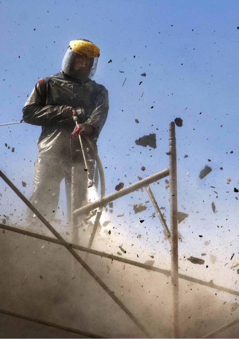
85
H P P › H i g h p r e s s u r e p u m p s
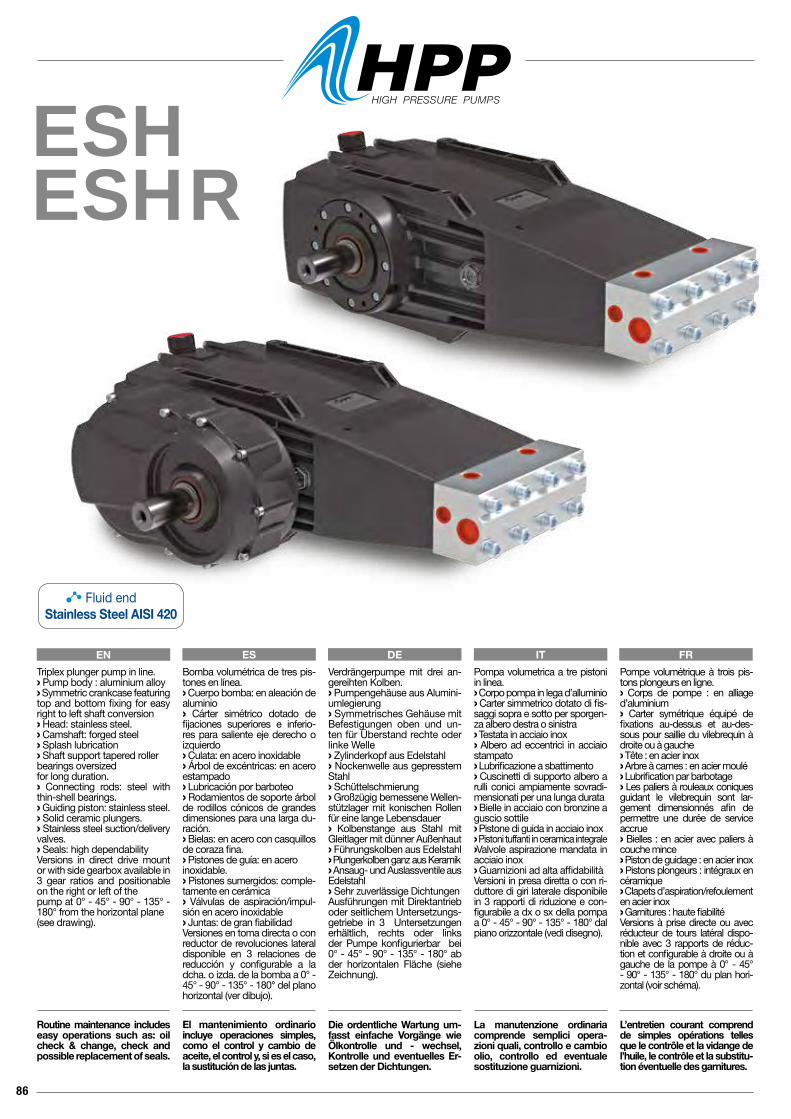
86
ESHESHR
Pompa volumetrica a tre pistoni in linea.› Corpo pompa in lega d’alluminio› Carter simmetrico dotato di fis-saggi sopra e sotto per sporgen-za albero destra o sinistra› Testata in acciaio inox› Albero ad eccentrici in acciaio stampato› Lubrificazione a sbattimento› Cuscinetti di supporto albero a rulli conici ampiamente sovradi-mensionati per una lunga durata› Bielle in acciaio con bronzine a guscio sottile› Pistone di guida in acciaio inox› Pistoni tuffanti in ceramica integrale› Valvole aspirazione mandata in acciaio inox› Guarnizioni ad alta affidabilitàVersioni in presa diretta o con ri-duttore di giri laterale disponibile in 3 rapporti di riduzione e con-figurabile a dx o sx della pompa a 0° - 45° - 90° - 135° - 180° dal piano orizzontale (vedi disegno).
La manutenzione ordinaria comprende semplici opera-zioni quali, controllo e cambio olio, controllo ed eventuale sostituzione guarnizioni.
Pompe volumétrique à trois pis-tons plongeurs en ligne.› Corps de pompe : en alliage d’aluminium› Carter symétrique équipé de fixations au-dessus et au-des-sous pour saillie du vilebrequin à droite ou à gauche› Tête : en acier inox› Arbre à cames : en acier moulé› Lubrification par barbotage› Les paliers à rouleaux coniques guidant le vilebrequin sont lar-gement dimensionnés afin de permettre une durée de service accrue› Bielles : en acier avec paliers à couche mince› Piston de guidage : en acier inox› Pistons plongeurs : intégraux en céramique› Clapets d’aspiration/refoulement en acier inox › Garnitures : haute fiabilitéVersions à prise directe ou avec réducteur de tours latéral dispo-nible avec 3 rapports de réduc-tion et configurable à droite ou à gauche de la pompe à 0° - 45° - 90° - 135° - 180° du plan hori-zontal (voir schéma).
L’entretien courant comprend de simples opérations telles que le contrôle et la vidange de l’huile, le contrôle et la substitu-tion éventuelle des garnitures.
Verdrängerpumpe mit drei an-gereihten Kolben.› Pumpengehäuse aus Alumini-umlegierung› Symmetrisches Gehäuse mit Befestigungen oben und un-ten für Überstand rechte oder linke Welle › Zylinderkopf aus Edelstahl› Nockenwelle aus gepresstem Stahl› Schüttelschmierung› Großzügig bemessene Wellen-stützlager mit konischen Rollen für eine lange Lebensdauer› Kolbenstange aus Stahl mit Gleitlager mit dünner Außenhaut › Führungskolben aus Edelstahl› Plungerkolben ganz aus Keramik› Ansaug- und Auslassventile aus Edelstahl› Sehr zuverlässige DichtungenAusführungen mit Direktantrieb oder seitlichem Untersetzungs-getriebe in 3 Untersetzungen erhältlich, rechts oder links der Pumpe konfigurierbar bei 0° - 45° - 90° - 135° - 180° ab der horizontalen Fläche (siehe Zeichnung).
Die ordentliche Wartung um-fasst einfache Vorgänge wie Ölkontrolle und - wechsel, Kontrolle und eventuelles Er-setzen der Dichtungen.
Bomba volumétrica de tres pis-tones en línea.› Cuerpo bomba: en aleación de aluminio› Cárter simétrico dotado de fijaciones superiores e inferio-res para saliente eje derecho o izquierdo› Culata: en acero inoxidable› Árbol de excéntricas: en acero estampado› Lubricación por barboteo› Rodamientos de soporte árbol de rodillos cónicos de grandes dimensiones para una larga du-ración.› Bielas: en acero con casquillos de coraza fina.› Pistones de guía: en aceroinoxidable.› Pistones sumergidos: comple-tamente en cerámica› Válvulas de aspiración/impul-sión en acero inoxidable› Juntas: de gran fiabilidadVersiones en toma directa o con reductor de revoluciones lateral disponible en 3 relaciones de reducción y configurable a la dcha. o izda. de la bomba a 0° - 45° - 90° - 135° - 180° del plano horizontal (ver dibujo).
El mantenimiento ordinario incluye operaciones simples, como el control y cambio de aceite, el control y, si es el caso, la sustitución de las juntas.
Triplex plunger pump in line.› Pump body : aluminium alloy › Symmetric crankcase featuring top and bottom fixing for easy right to left shaft conversion› Head: stainless steel.› Camshaft: forged steel› Splash lubrication› Shaft support tapered roller bearings oversizedfor long duration.› Connecting rods: steel with thin-shell bearings.› Guiding piston: stainless steel.› Solid ceramic plungers. › Stainless steel suction/delivery valves.› Seals: high dependability Versions in direct drive mount or with side gearbox available in3 gear ratios and positionable on the right or left of the pump at 0° - 45° - 90° - 135° - 180° from the horizontal plane (see drawing).
Routine maintenance includes easy operations such as: oil check & change, check and possible replacement of seals.
EN ES DE IT FR
Fluid endStainless Steel AISI 420
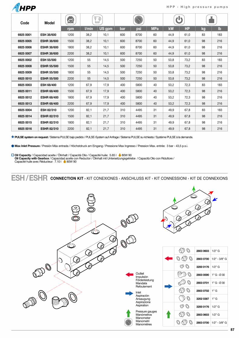
87
H P P › H i g h p r e s s u r e p u m p s
Code Modelrpm l/min US gpm bar psi MPa kW HP kg lb
6925 0001 ESH 38/600 1200 38,2 10,1 600 8700 60 44,9 61,0 83 183
6925 0005 ESHR 38/600 1500 38,2 10,1 600 8700 60 44,9 61,0 98 216
6925 0006 ESHR 38/600 1800 38,2 10,1 600 8700 60 44,9 61,0 98 216
6925 0007 ESHR 38/600 2200 38,2 10,1 600 8700 60 44,9 61,0 98 216
6925 0002 ESH 55/500 1200 55 14,5 500 7250 50 53,8 73,2 83 183
6925 0008 ESHR 55/500 1500 55 14,5 500 7250 50 53,8 73,2 98 216
6925 0009 ESHR 55/500 1800 55 14,5 500 7250 50 53,8 73,2 98 216
6925 0010 ESHR 55/500 2200 55 14,5 500 7250 50 53,8 73,2 98 216
6925 0003 ESH 68/400 1200 67,9 17,9 400 5800 40 53,2 72,3 83 183
6925 0011 ESHR 68/400 1500 67,9 17,9 400 5800 40 53,2 72,3 98 216
6925 0012 ESHR 68/400 1800 67,9 17,9 400 5800 40 53,2 72,3 98 216
6925 0013 ESHR 68/400 2200 67,9 17,9 400 5800 40 53,2 72,3 98 216
6925 0004 ESH 82/310 1200 82,1 21,7 310 4495 31 49,9 67,8 83 183
6925 0014 ESHR 82/310 1500 82,1 21,7 310 4495 31 49,9 67,8 98 216
6925 0015 ESHR 82/310 1800 82,1 21,7 310 4495 31 49,9 67,8 98 216
6925 0016 ESHR 82/310 2200 82,1 21,7 310 4495 31 49,9 67,8 98 216
OutletImpulsiónFörderleistungMandataRefoulement
InletAspiraciónAnsaugungAspirazioneAspiration
Pressure gaugesManómetrosManometerManometriManomètres
2803 0603 1/2” G
2803 0700 1/2” - 3/8” G
3200 0176 1/2” G
2803 0590 1” G - Ø 30
2803 0701 1” G - Ø 30
2803 0702 1” G
3202 0387 1” G
3200 0176 1/2” G
2803 0603 1/2” G
2803 0700 1/2” - 3/8” G
CONNECTION KIT › KIT CONEXIONES › ANSCHLUSS KIT › KIT CONNESSIONI › KIT DE CONNEXIONSESH / ESHR
PULSE system on request / Sistema PULSE bajo pedido / PULSE-System auf Anfrage / Sistema PULSE su richiesta / Système PULSE à la demande.
Max Inlet Pressure / Presión Máx entrada / Höchstdruck am Eingang / Pressione Max Ingresso / Pression Max. entrée: 3 bar - 43,5 p.s.i.
Oil Capacity / Capacidad aceite / Ölinhalt / Capacità Olio / Capacité huile: 5.65 l 80W 90Oil Capacity with Gearbox / Capacidad aceite con Reductor / Ölinhalt mit Untersetzungsgetriebe / Capacità Olio con Riduttore / Capacité huile avec Réducteur: 7.10 l 80W 90
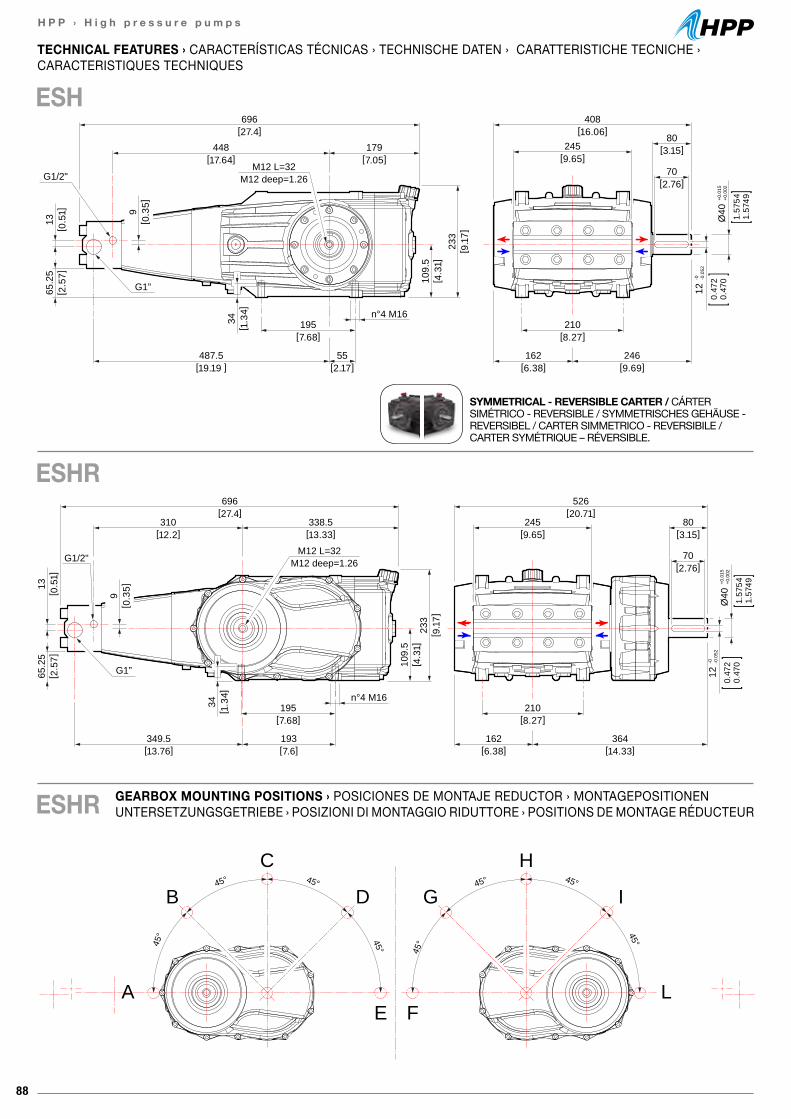
88
H P P › H i g h p r e s s u r e p u m p s
45° 45°
45° 45°
A
B
C
D
E
45°45°
45°
45°
L
I
H
G
F
696[27.4]
526[20.71]
310[12.2]
338.5[13.33]
233
[ 9.1
7]
109.
5[ 4
.31]
195[7.68]
349.5[13.76]
193[7.6]
n°4 M16
65.2
5[ 2
.57]
13[ 0
.51]
9[ 0
.35]
245[9.65]
80[3.15]
70[2.76]
210[8.27]
364[14.33]
162[6.38]
G1”
G1/2"
12-0 -0
.052
0.47
20.
470
Ø40
+0.0
15+0
.002
1.57
541.
5749
M12 L=32M12 deep=1.26
34[ 1
.34]
696[27.4]
408[16.06]
448[17.64]
179[7.05]
233
[ 9.1
7]
109.
5[ 4
.31]
195[7.68]
487.5[19.19 ]
55[2.17]
n°4 M16
65.2
5[ 2
.57]
13[ 0
.51] 9
[ 0.3
5]245
[9.65]
80[3.15]
70[2.76]
210[8.27]
246[9.69]
162[6.38]
G1”
G1/2"M12 L=32
M12 deep=1.26
Ø40
+0.0
15+0
.002
1.57
541.
5749
0.47
20.
470
12-0 -0
.052
34[ 1
.34]
GEARBOX MOUNTING POSITIONS › POSICIONES DE MONTAJE REDUCTOR › MONTAGEPOSITIONEN UNTERSETZUNGSGETRIEBE › POSIZIONI DI MONTAGGIO RIDUTTORE › POSITIONS DE MONTAGE RÉDUCTEUR
TECHNICAL FEATURES › CARACTERÍSTICAS TÉCNICAS › TECHNISCHE DATEN › CARATTERISTICHE TECNICHE ›CARACTERISTIQUES TECHNIQUES
ESH
ESHR
SYMMETRICAL - REVERSIBLE CARTER / CÁRTER SIMÉTRICO - REVERSIBLE / SYMMETRISCHES GEHÄUSE - REVERSIBEL / CARTER SIMMETRICO - REVERSIBILE / CARTER SYMÉTRIQUE – RÉVERSIBLE.
ESHR

89
H P P › H i g h p r e s s u r e p u m p s
17.75[0.7]
22 max[0.87 max]
12[0.47]
Ø56
-0.0
1-0
.04
2.20
432.
2031
Ø40
[ 1.5
7]
M8 L=12M8 deep=0.47
17.75[0.7]
22 max[0.87 max]
12[0.47]
Ø56
-0.0
1-0
.04
2.20
432.
2031
Ø40
[ 1.5
7]
M8 L=12M8 deep=0.47
ESH
ESH
ESH
Kit Code 5003 0054Max torque
Par máx.Max. Drehmoment
Coppia max.Couple max.
Max powerPotencia máx.Max. LeistungPotenza max.
Puissance max.[Nm] [Hp] rpm
Pulley/beltsCorreasRiemenCinghieCourroies
65
7,07,48,39,311,1
75080090010001200
Flex joint directAcoplamiento directoDirekte VerbindungGiunto direttoAccouplement direct
130
14,014,816,618,622,2
75080090010001200
82.75[3.26]
Ø144[5.67]
Ø99[3.9]
80[3.15]
32[1.26]
8[0.31]
M12
M8
Ø117 +0.035-0
4.6084.606
Ø40
+0.0
18+0
.002
1.57
61.
575
114.5[4.51]
18.2[0.72]
114.
5[ 4
.51]
181[7.13]
85[3.35]
M14 L=34M14 deep=1.34
M16 L=39M16 deep=1.42
191 +0.05-0.05
7.5227.518
Ø31.75 +0.05+0.03
1.2521.251
Ø7.94 +0.156+0.07
0.3190.315
Ø12
7+0
.1+0
.05
5.00
45.
002
35.5
+0.0
2+0
1.40
61.
398
FLANGE FOR DIRECT DRIVE MOUNT › BRIDA SOPORTE PARA ACCIONAMIENTOS DIRECTOS › TRÄGERFLANSCH FÜR DIREKTE ANTRIEBE › FLANGIA SUPPORTO PER AZIONAMENTI DIRETTI › BRIDE SUPPORT POUR ACTIONNEMENTS DIRECTS
BELL HOUSING AND COUPLING FOR HYDRAULIC MOTOR › KIT CAMPANA Y JUNTA PARA ACOPLAMIENTO A MOTO-RES HIDRÁULICOS › GLOCKEN- UND VERBINDUNGSSET FÜR KOPPLUNG MIT HYDRAULIKMOTOREN › KIT CAMPANA E GIUNTO PER ACCOPPIAMENTO A MOTORI IDRAULICI › KIT CLOCHE ET JOINT POUR ACCOUPLEMENT À DES MO-TEURS HYDRAULIQUES
AUXILIARY P.T.O. OPPOSITE TO SHAFT SIDE › PREINSTALACIÓN TOMA DE FUERZA AUXILIAR OPUESTA EJE MOVIMIENTO › VORRÜSTUNG NEBENANTRIEB ENTGEGENGESETZT ZUR ANTRIEBSWELLE › PREDISPOSIZIONE PRESA DI FORZA AUSILIA-RIA OPPOSTA ALBERO MOTO › PRÉ-ÉQUIPEMENT PRISE DE FORCE AUXILIAIRE OPPOSÉE À L’ARBRE D’ENTRAÎNEMENT.
SAE J 744 C
Kit Code:5011 0296 BELL / CAMPANAGLOCKE / CAMPANACLOCHE1221 0060 COUPLING / JUNTAKOPPLUNG / GIUNTOJOINT
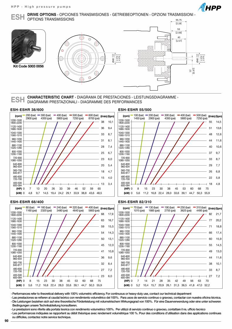
90
H P P › H i g h p r e s s u r e p u m p s
ESH-ESHR 38/600(l/min)
38
36
33
31
28
25
23
20
18
15
13
(Gpm)
10,1
9,4
8,7
8,1
7,4
6,7
6,0
5,4
4,7
4,0
3,4
200 (bar) 300 (bar) 400 (bar) 500 (bar) 600 (bar)2900 (psi) 4350 (psi) 5800 (psi) 7250 (psi) 8700 (psi)
(HP) 0 7 13 20 26 33 39 46 52 59 65(kW) 0 4,8 9,7 14,5 19,4 24,2 29,1 33,9 38,8 43,6 48,5
(rpm)1200-15001800-22001120-14001680-16301040-13001560-1510960-1200
1440-1400880-1100
1320-1280800-1000
1200-1160720-900
1080-1050640-800960-934560-700840-817480-600720-700400-500600-584
ESH-ESHR 68/400(l/min)
68
63
59
54
50
45
41
36
32
27
23
(Gpm)
17,9
16,7
15,5
14,3
13,1
12,0
10,8
9,6
8,4
7,2
6,0
80 (bar) 160 (bar) 240 (bar) 320 (bar) 400 (bar)1160 (psi) 2320 (psi) 3480 (psi) 4640 (psi) 5800 (psi)
(HP) 0 8 15 23 30 38 45 53 60 68 75(kW) 0 5,6 11,2 16,8 22,4 28,0 33,6 39,1 44,7 50,3 55,9
(rpm)1200-15001800-22001120-14001680-16301040-13001560-1510960-1200
1440-1400880-1100
1320-1280800-1000
1200-1160720-900
1080-1050640-800960-934560-700840-817480-600720-700400-500600-584
ESH-ESHR 82/310(l/min)
82
77
71
66
60
55
49
44
38
33
27
(Gpm)
21,7
20,2
18,8
17,4
15,9
14,5
13,0
11,6
10,1
8,7
7,2
70 (bar) 130 (bar) 190 (bar) 250 (bar) 310 (bar)1015 (psi) 1885 (psi) 2755 (psi) 3625 (psi) 4495 (psi)
(HP) 0 7 14 21 28 35 42 49 56 63 70(kW) 0 5,2 10,4 15,7 20,9 26,1 31,3 36,5 41,8 47,0 52,2
(rpm)1200-15001800-22001120-14001680-16301040-13001560-1510960-1200
1440-1400880-1100
1320-1280800-1000
1200-1160720-900
1080-1050640-800960-934560-700840-817480-600720-700400-500600-584
ESH-ESHR 55/500(l/min)
55
51
48
44
40
37
33
29
26
22
18
(Gpm)
14,5
13,6
12,6
11,6
10,6
9,7
8,7
7,7
6,8
5,8
4,8
100 (bar) 200 (bar) 300 (bar) 400 (bar) 500 (bar)1450 (psi) 2900 (psi) 4350 (psi) 5800 (psi) 7250 (psi)
(HP) 0 8 15 23 30 38 45 53 60 68 75(kW) 0 5,6 11,2 16,8 22,4 28,0 33,6 39,1 44,7 50,3 55,9
(rpm)1200-15001800-22001120-14001680-16301040-13001560-1510960-1200
1440-1400880-1100
1320-1280800-1000
1200-1160720-900
1080-1050640-800960-934560-700840-817480-600720-700400-500600-584
DRIVE OPTIONS › OPCIONES TRANSMISIONES › GETRIEBEOPTIONEN › OPZIONI TRASMISSIONI › OPTIONS TRANSMISSIONSESH 55.75
[2.19]
12[ 0
.47]
53[2.08]
40[1.57]
Ø40
+0.0
18+0
.002
1.57
61.
575
Ø40
+0.0
18+0
.002
1.57
61.
575
CHARACTERISTIC CHART › DIAGRAMA DE PRESTACIONES › LEISTUNGSDIAGRAMME ›DIAGRAMMI PRESTAZIONALI › DIAGRAMME DES PERFORMANCESESH
Kit Code 5003 0056
› Performances refer to theoretical delivery with 100% volumetric efficiency. For continuous or heavy-duty use, contact our technical department› Las prestaciones se refieren al caudal teórico con rendimiento volumétrico del 100%. Para usos de servicio continuo o gravoso, contactar con nuestra oficina técnica.› Die Leistungen beziehen sich auf eine theoretische Förderleistung mit volumetrischem Wirkungsgrad von 100%. Für eine Dauerverwendung oder eine unter schweren Bedingungen unsere Technikabteilung konsultieren.› Le prestazioni sono riferite alla portata teorica con rendimento volumetrico 100%. Per utilizzi di servizio continuo o gravoso, contattare il ns. ufficio tecnico› Les performances indiquées se rapportent au débit théorique avec rendement volumétrique 100 %. Pour des conditions d’utilisation dans des applications continues ou difficiles, contactez notre service technique.
91
H P P › H i g h p r e s s u r e p u m p s
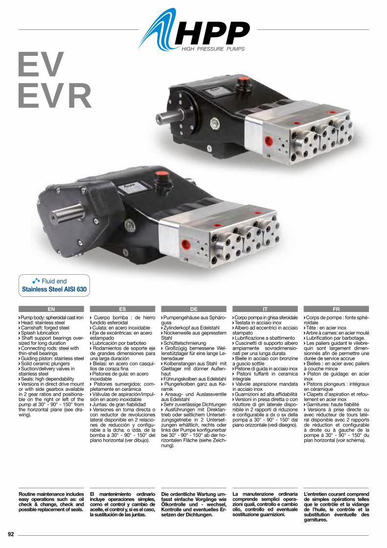
92
EVEVR
EN ES DE IT FR Corpo pompa in ghisa sferoidale Testata in acciaio inox Albero ad eccentrici in acciaio stampato Lubrificazione a sbattimento Cuscinetti di supporto albero ampiamente sovradimensio-nati per una lunga durata Bielle in acciaio con bronzine a guscio sottile Pistone di guida in acciaio inox Pistoni tuffanti in ceramica integrale Valvole aspirazione mandata in acciaio inox Guarnizioni ad alta affidabilità Versioni in presa diretta o con riduttore di giri laterale dispo-nibile in 2 rapporti di riduzione e configurabile a dx o sx della pompa a 30° - 90° - 150° dal piano orizzontale (vedi disegno).
La manutenzione ordinaria comprende semplici opera-zioni quali, controllo e cambio olio, controllo ed eventuale sostituzione guarnizioni.
Pump body: spheroidal cast iron Head: stainless steel Camshaft: forged steel Splash lubrication Shaft support bearings over-sized for long duration Connecting rods: steel withthin-shell bearings Guiding piston: stainless steel Solid ceramic plungers Suction/delivery valves instainless steel Seals: high dependability Versions in direct drive mount or with side gearbox available in 2 gear ratios and positiona-ble on the right or left of the pump at 30° - 90° - 150° from the horizontal plane (see dra-wing).
Routine maintenance includes easy operations such as: oil check & change, check and possible replacement of seals.
Cuerpo bomba : de hierro fundido esferoidal Culata: en acero inoxidable Eje de excéntricas: en aceroestampado Lubricación por barboteo Rodamientos de soporte eje de grandes dimensiones para una larga duración Bielas: en acero con casqui-llos de coraza fina Pistones de guía: en aceroinoxidable Pistones sumergidos: com-pletamente en cerámica Válvulas de aspiración/impul-sión en acero inoxidable Juntas: de gran fiabilidad Versiones en toma directa o con reductor de revoluciones lateral disponible en 2 relacio-nes de reducción y configu-rable a la dcha. o izda. de la bomba a 30° - 90° - 150° del plano horizontal (ver dibujo).
El mantenimiento ordinario incluye operaciones simples, como el control y cambio de aceite, el control y, si es el caso, la sustitución de las juntas.
Pumpengehäuse aus Sphäro-guss Zylinderkopf aus Edelstahl Nockenwelle aus gepresstem Stahl Schüttelschmierung Großzügig bemessene Wel-lenstützlager für eine lange Le-bensdauer Kolbenstangen aus Stahl mit Gleitlager mit dünner Außen-haut Führungskolben aus Edelstahl Plungerkolben ganz aus Ke-ramik Ansaug- und Auslassventile aus Edelstahl Sehr zuverlässige Dichtungen Ausführungen mit Direktan-trieb oder seitlichem Unterset-zungsgetriebe in 2 Unterset-zungen erhältlich, rechts oder links der Pumpe konfigurierbarbei 30° - 90° - 150° ab der ho-rizontalen Fläche (siehe Zeich-nung).
Die ordentliche Wartung um-fasst einfache Vorgänge wie Ölkontrolle und - wechsel, Kontrolle und eventuelles Er-setzen der Dichtungen.
Corps de pompe : fonte sphé-roïdale Tête : en acier inox Arbre à cames: en acier moulé Lubrification par barbotage. Les paliers guidant le vilebre-quin sont largement dimen-sionnés afin de permettre une durée de service accrue Bielles : en acier avec paliers à couche mince Piston de guidage: en acier inox Pistons plongeurs : intégraux en céramique Clapets d’aspiration et refou-lement en acier inox Garnitures: haute fiabilité Versions à prise directe ou avec réducteur de tours laté-ral disponible avec 2 rapports de réduction et configurable à droite ou à gauche de la pompe à 30° - 90° - 150° du plan horizontal (voir schéma).
L’entretien courant comprend de simples opérations telles que le contrôle et la vidange de l’huile, le contrôle et la substitution éventuelle des garnitures.
Fluid endStainless Steel AISI 630
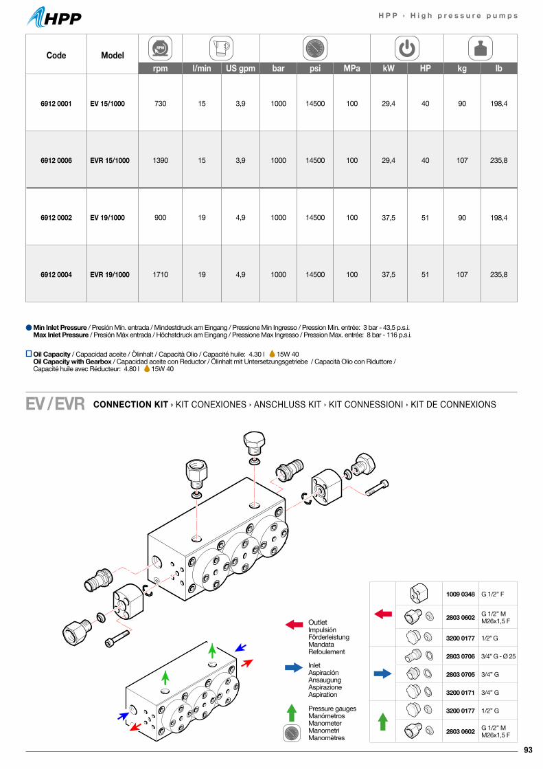
93
H P P › H i g h p r e s s u r e p u m p s
Code Modelrpm l/min US gpm bar psi MPa kW HP kg lb
6912 0001 EV 15/1000 730 15 3,9 1000 14500 100 29,4 40 90 198,4
6912 0006 EVR 15/1000 1390 15 3,9 1000 14500 100 29,4 40 107 235,8
6912 0002 EV 19/1000 900 19 4,9 1000 14500 100 37,5 51 90 198,4
6912 0004 EVR 19/1000 1710 19 4,9 1000 14500 100 37,5 51 107 235,8
CONNECTION KIT › KIT CONEXIONES › ANSCHLUSS KIT › KIT CONNESSIONI › KIT DE CONNEXIONSEV / EVR
Min Inlet Pressure / Presión Mín. entrada / Mindestdruck am Eingang / Pressione Min Ingresso / Pression Min. entrée: 3 bar - 43,5 p.s.i.Max Inlet Pressure / Presión Máx entrada / Höchstdruck am Eingang / Pressione Max Ingresso / Pression Max. entrée: 8 bar - 116 p.s.i.
OutletImpulsiónFörderleistungMandataRefoulement
InletAspiraciónAnsaugungAspirazioneAspiration
Pressure gaugesManómetrosManometerManometriManomètres
1009 0348 G 1/2” F
2803 0602 G 1/2” M M26x1,5 F
3200 0177 1/2” G
2803 0706 3/4” G - Ø 25
2803 0705 3/4” G
3200 0171 3/4” G
3200 0177 1/2” G
2803 0602 G 1/2” M M26x1,5 F
Oil Capacity / Capacidad aceite / Ölinhalt / Capacità Olio / Capacité huile: 4.30 l 15W 40Oil Capacity with Gearbox / Capacidad aceite con Reductor / Ölinhalt mit Untersetzungsgetriebe / Capacità Olio con Riduttore / Capacité huile avec Réducteur: 4.80 l 15W 40
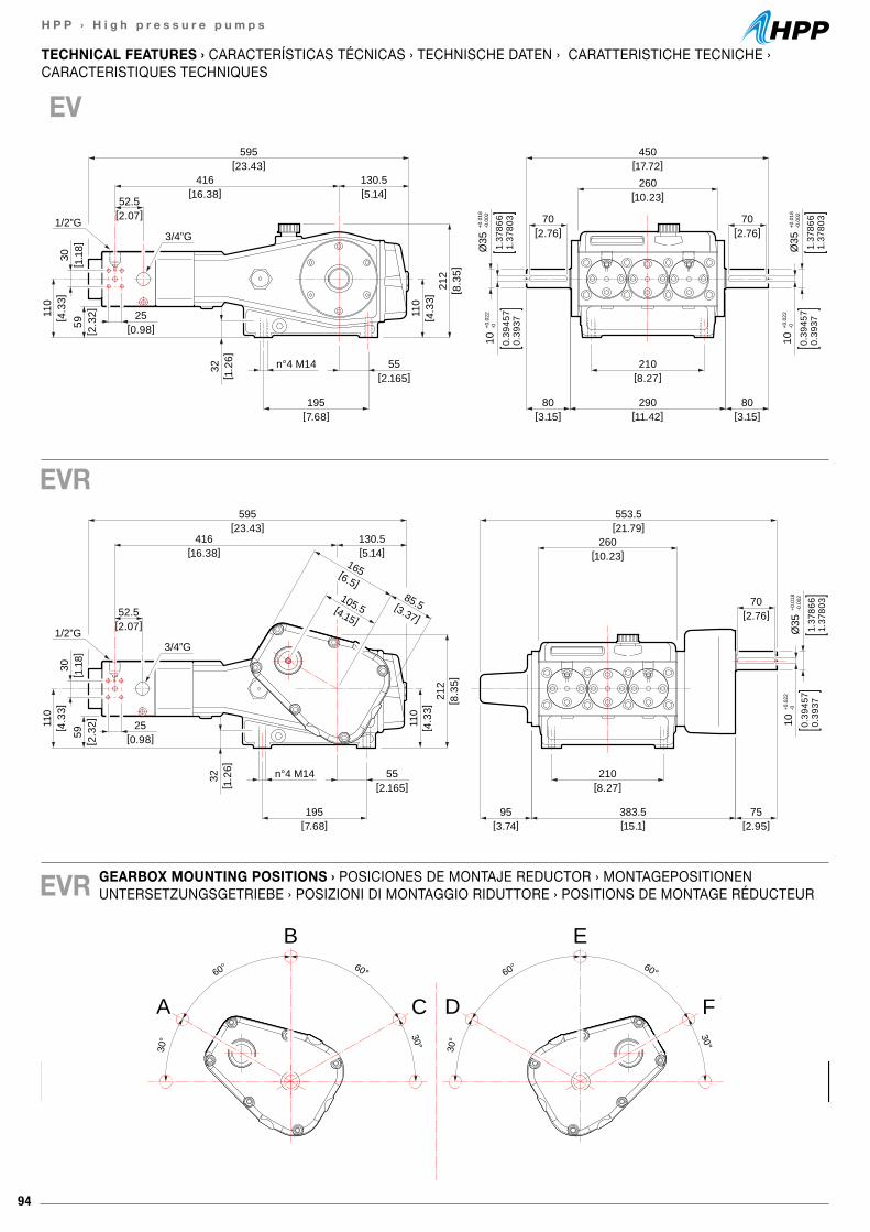
94
H P P › H i g h p r e s s u r e p u m p s
[21.79]553.5
[10.23]260
[2.07]52.5
[ 2.3
2]59
[ 1.1
8]30
[ 4.3
3]11
0
[2.76]70
10+0
.022
-0
0.39
457
0.39
371.
3786
61.
3780
3
Ø35
+0.0
18-0
.002
[8.27]210
[0.98]25
[3.74]95
[2.95]75
[15.1]383.5
110
[ 4.3
3]21
2[ 8
.35]
[7.68]195
3/4”G1/2”G
[2.165]55n°4 M14
[5.14]130.5
[23.43]595
[16.38]416
32[ 1
.26]
[6.5]
165
[4.15]
105.5 [3.37]
85.5
[17.72]450
[10.23]260
[2.76]70
[2.76]70[2.07]
52.5
[ 2.3
2]59
[ 1.1
8]30
[ 4.3
3]11
0
10+0
.022
-0
0.39
457
0.39
37
10+0
.022
-0
0.39
457
0.39
37
1.37
866
1.37
803
Ø35
+0.0
18-0
.002
1.37
866
1.37
803
Ø35
+0.0
18-0
.002
[8.27]210
[0.98]25
[3.15]80
[3.15]80
[11.42]290
110
[ 4.3
3]21
2[ 8
.35]
[7.68]195
3/4”G1/2”G
[2.165]55n°4 M14
[5.14]130.5
[23.43]595
[16.38]416
32[ 1
.26]
GEARBOX MOUNTING POSITIONS › POSICIONES DE MONTAJE REDUCTOR › MONTAGEPOSITIONEN UNTERSETZUNGSGETRIEBE › POSIZIONI DI MONTAGGIO RIDUTTORE › POSITIONS DE MONTAGE RÉDUCTEUR
TECHNICAL FEATURES › CARACTERÍSTICAS TÉCNICAS › TECHNISCHE DATEN › CARATTERISTICHE TECNICHE ›CARACTERISTIQUES TECHNIQUES
EV
EVR
EVR
60° 60°
30° 30°
A
B
C
60° 60°
30° 30°
D
E
F
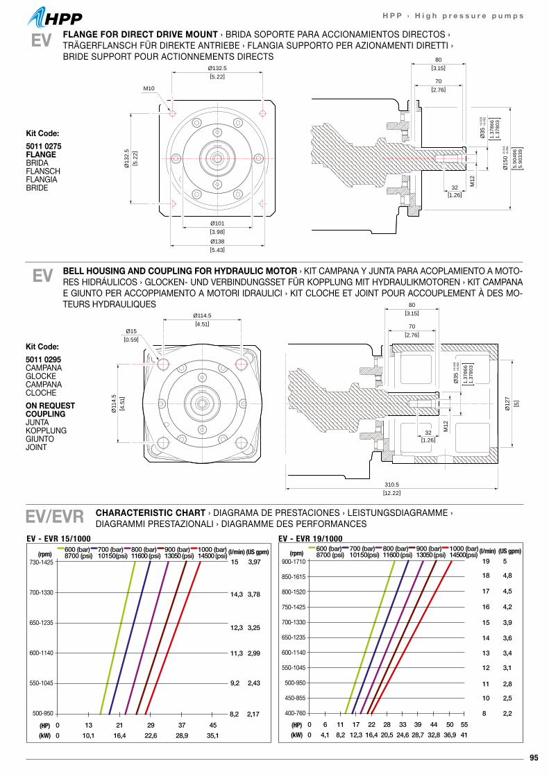
95
H P P › H i g h p r e s s u r e p u m p s
80[3.15]Ø114.5
[4.51]
Ø11
4.5
[ 4.5
1]
70[2.76]
32[1.26]
M12
Ø15
Ø35
+0.0
18+0
.002
1.37
866
1.37
803
[ 5]
Ø12
7
[0.59]
310.5 [12.22]
Kit Code:5011 0295 CAMPANAGLOCKECAMPANACLOCHEON REQUEST COUPLINGJUNTAKOPPLUNGGIUNTOJOINT
BELL HOUSING AND COUPLING FOR HYDRAULIC MOTOR › KIT CAMPANA Y JUNTA PARA ACOPLAMIENTO A MOTO-RES HIDRÁULICOS › GLOCKEN- UND VERBINDUNGSSET FÜR KOPPLUNG MIT HYDRAULIKMOTOREN › KIT CAMPANA E GIUNTO PER ACCOPPIAMENTO A MOTORI IDRAULICI › KIT CLOCHE ET JOINT POUR ACCOUPLEMENT À DES MO-TEURS HYDRAULIQUES
EV
80[3.15]Ø132.5
[5.22]
Ø101[3.98]
Ø138[5.43]
Ø13
2.5
[ 5.2
2]
70[2.76]
32[1.26]
M12
M10
Ø35
+0.0
18+0
.002
1.37
866
1.37
803
Ø15
0-0
.014
-0.0
54
5.90
496
5.90
339
80[3.15]Ø132.5
[5.22]
Ø101[3.98]
Ø138[5.43]
Ø13
2.5
[ 5.2
2]
70[2.76]
32[1.26]
M12
M10
Ø35
+0.0
18+0
.002
1.37
866
1.37
803
Ø15
0-0
.014
-0.0
54
5.90
496
5.90
339
EV/EVR
EV FLANGE FOR DIRECT DRIVE MOUNT › BRIDA SOPORTE PARA ACCIONAMIENTOS DIRECTOS › TRÄGERFLANSCH FÜR DIREKTE ANTRIEBE › FLANGIA SUPPORTO PER AZIONAMENTI DIRETTI › BRIDE SUPPORT POUR ACTIONNEMENTS DIRECTS
EV - EVR 15/1000
15 3,97
0 13 21 29 37 450 10,1 16,4 22,6 28,9 35,1
(HP)(kW)
600 (bar)8700 (psi)
700 (bar)10150(psi)
800 (bar)11600 (psi)
900 (bar)13050 (psi)
1000 (bar)14500 (psi) (l/min) (US gpm)
730-1425
700-1330
650-1235
600-1140
550-1045
500-950
(rpm)
14,3 3,78
12,3 3,25
11,3 2,99
9,2 2,43
8,2 2,17
900-1710
850-1615
800-1520
750-1425
700-1330
650-1235
600-1140
550-1045
500-950
450-855
400-760
19 5
18 4,8
0 11 176 22 28 33 39 44 50 550 8,2 12,34,1 16,4 20,5 24,6 28,7 32,8 36,9 41
(HP)(kW)
17 4,5
16 4,2
15 3,9
14 3,6
13 3,4
12 3,1
11 2,8
10 2,5
8 2,2
600 (bar)8700 (psi)
700 (bar)10150(psi)
800 (bar)11600 (psi)
900 (bar)13050 (psi)
1000 (bar)14500(psi) (l/min) (US gpm)(rpm)
EV - EVR 19/1000
CHARACTERISTIC CHART › DIAGRAMA DE PRESTACIONES › LEISTUNGSDIAGRAMME ›DIAGRAMMI PRESTAZIONALI › DIAGRAMME DES PERFORMANCES
Kit Code:5011 0275 FLANGEBRIDAFLANSCHFLANGIABRIDE
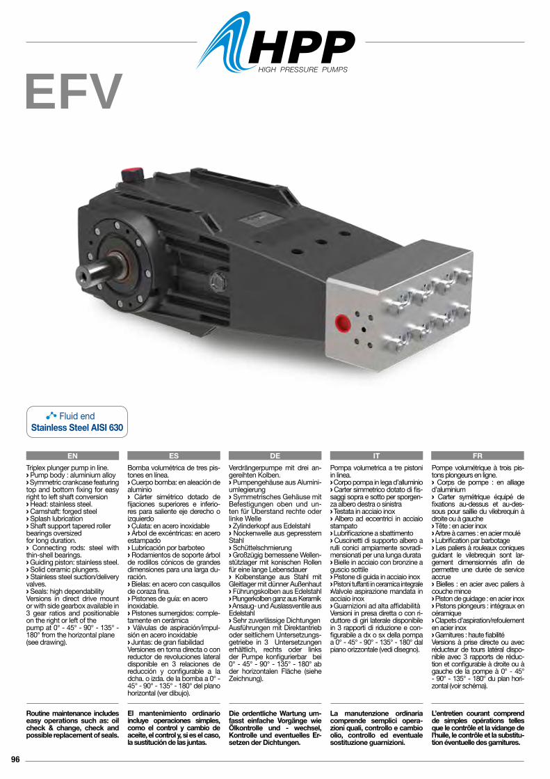
96
EFV
Pompa volumetrica a tre pistoni in linea.› Corpo pompa in lega d’alluminio› Carter simmetrico dotato di fis-saggi sopra e sotto per sporgen-za albero destra o sinistra› Testata in acciaio inox› Albero ad eccentrici in acciaio stampato› Lubrificazione a sbattimento› Cuscinetti di supporto albero a rulli conici ampiamente sovradi-mensionati per una lunga durata› Bielle in acciaio con bronzine a guscio sottile› Pistone di guida in acciaio inox› Pistoni tuffanti in ceramica integrale› Valvole aspirazione mandata in acciaio inox› Guarnizioni ad alta affidabilitàVersioni in presa diretta o con ri-duttore di giri laterale disponibile in 3 rapporti di riduzione e con-figurabile a dx o sx della pompa a 0° - 45° - 90° - 135° - 180° dal piano orizzontale (vedi disegno).
La manutenzione ordinaria comprende semplici opera-zioni quali, controllo e cambio olio, controllo ed eventuale sostituzione guarnizioni.
Pompe volumétrique à trois pis-tons plongeurs en ligne.› Corps de pompe : en alliage d’aluminium› Carter symétrique équipé de fixations au-dessus et au-des-sous pour saillie du vilebrequin à droite ou à gauche› Tête : en acier inox› Arbre à cames : en acier moulé› Lubrification par barbotage› Les paliers à rouleaux coniques guidant le vilebrequin sont lar-gement dimensionnés afin de permettre une durée de service accrue› Bielles : en acier avec paliers à couche mince› Piston de guidage : en acier inox› Pistons plongeurs : intégraux en céramique› Clapets d’aspiration/refoulement en acier inox › Garnitures : haute fiabilitéVersions à prise directe ou avec réducteur de tours latéral dispo-nible avec 3 rapports de réduc-tion et configurable à droite ou à gauche de la pompe à 0° - 45° - 90° - 135° - 180° du plan hori-zontal (voir schéma).
L’entretien courant comprend de simples opérations telles que le contrôle et la vidange de l’huile, le contrôle et la substitu-tion éventuelle des garnitures.
Verdrängerpumpe mit drei an-gereihten Kolben.› Pumpengehäuse aus Alumini-umlegierung› Symmetrisches Gehäuse mit Befestigungen oben und un-ten für Überstand rechte oder linke Welle › Zylinderkopf aus Edelstahl› Nockenwelle aus gepresstem Stahl› Schüttelschmierung› Großzügig bemessene Wellen-stützlager mit konischen Rollen für eine lange Lebensdauer› Kolbenstange aus Stahl mit Gleitlager mit dünner Außenhaut › Führungskolben aus Edelstahl› Plungerkolben ganz aus Keramik› Ansaug- und Auslassventile aus Edelstahl› Sehr zuverlässige DichtungenAusführungen mit Direktantrieb oder seitlichem Untersetzungs-getriebe in 3 Untersetzungen erhältlich, rechts oder links der Pumpe konfigurierbar bei 0° - 45° - 90° - 135° - 180° ab der horizontalen Fläche (siehe Zeichnung).
Die ordentliche Wartung um-fasst einfache Vorgänge wie Ölkontrolle und - wechsel, Kontrolle und eventuelles Er-setzen der Dichtungen.
Bomba volumétrica de tres pis-tones en línea.› Cuerpo bomba: en aleación de aluminio› Cárter simétrico dotado de fijaciones superiores e inferio-res para saliente eje derecho o izquierdo› Culata: en acero inoxidable› Árbol de excéntricas: en acero estampado› Lubricación por barboteo› Rodamientos de soporte árbol de rodillos cónicos de grandes dimensiones para una larga du-ración.› Bielas: en acero con casquillos de coraza fina.› Pistones de guía: en aceroinoxidable.› Pistones sumergidos: comple-tamente en cerámica› Válvulas de aspiración/impul-sión en acero inoxidable› Juntas: de gran fiabilidadVersiones en toma directa o con reductor de revoluciones lateral disponible en 3 relaciones de reducción y configurable a la dcha. o izda. de la bomba a 0° - 45° - 90° - 135° - 180° del plano horizontal (ver dibujo).
El mantenimiento ordinario incluye operaciones simples, como el control y cambio de aceite, el control y, si es el caso, la sustitución de las juntas.
Triplex plunger pump in line.› Pump body : aluminium alloy › Symmetric crankcase featuring top and bottom fixing for easy right to left shaft conversion› Head: stainless steel.› Camshaft: forged steel› Splash lubrication› Shaft support tapered roller bearings oversizedfor long duration.› Connecting rods: steel with thin-shell bearings.› Guiding piston: stainless steel.› Solid ceramic plungers. › Stainless steel suction/delivery valves.› Seals: high dependability Versions in direct drive mount or with side gearbox available in3 gear ratios and positionable on the right or left of the pump at 0° - 45° - 90° - 135° - 180° from the horizontal plane (see drawing).
Routine maintenance includes easy operations such as: oil check & change, check and possible replacement of seals.
EN ES DE IT FR
Fluid endStainless Steel AISI 630
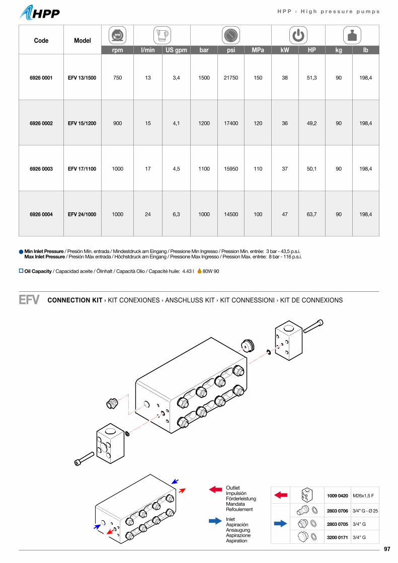
97
H P P › H i g h p r e s s u r e p u m p s
Code Modelrpm l/min US gpm bar psi MPa kW HP kg lb
6926 0001 EFV 13/1500 750 13 3,4 1500 21750 150 38 51,3 90 198,4
6926 0002 EFV 15/1200 900 15 4,1 1200 17400 120 36 49,2 90 198,4
6926 0003 EFV 17/1100 1000 17 4,5 1100 15950 110 37 50,1 90 198,4
6926 0004 EFV 24/1000 1000 24 6,3 1000 14500 100 47 63,7 90 198,4
CONNECTION KIT › KIT CONEXIONES › ANSCHLUSS KIT › KIT CONNESSIONI › KIT DE CONNEXIONSEFV
Min Inlet Pressure / Presión Mín. entrada / Mindestdruck am Eingang / Pressione Min Ingresso / Pression Min. entrée: 3 bar - 43,5 p.s.i.Max Inlet Pressure / Presión Máx entrada / Höchstdruck am Eingang / Pressione Max Ingresso / Pression Max. entrée: 8 bar - 116 p.s.i.
OutletImpulsiónFörderleistungMandataRefoulement
InletAspiraciónAnsaugungAspirazioneAspiration
1009 0420 M26x1,5 F
2803 0706 3/4” G - Ø 25
2803 0705 3/4” G
3200 0171 3/4” G
Oil Capacity / Capacidad aceite / Ölinhalt / Capacità Olio / Capacité huile: 4.43 l 80W 90
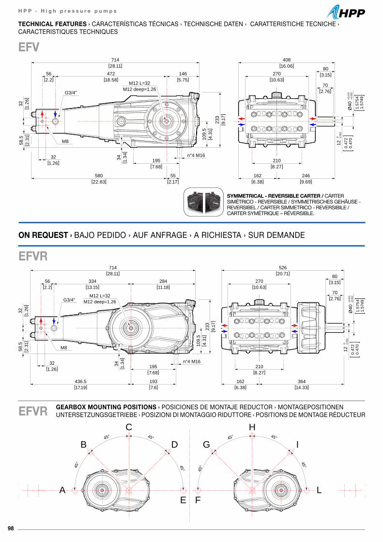
98
H P P › H i g h p r e s s u r e p u m p s
45° 45°
45° 45°
A
B
C
D
E
45°45°
45°
45°
L
I
H
G
F
270[10.63]
80[3.15]
70[2.76]
210[8.27]
162[6.38]
Ø40
+0.0
15+0
.002
1.57
541.
5749
0.47
20.
470
12-0 -0
.052
714[28.11]
334[13.15]
56[2.2]
284[11.18]
233
[ 9.1
7]
109.
5[ 4
.31]
195[7.68]
436.5[17.19]
193[7.6]
32[1.26]
32[ 1
.26]
n°4 M16
58.5
[ 2.3
1]
G3/4"
M8
M12 L=32M12 deep=1.26
526[20.71]
364[14.33]
34[ 1
.34]
408[16.06]
270[10.63]
80[3.15]
70[2.76]
210[8.27]
246[9.69]
162[6.38]
Ø40
+0.0
15+0
.002
1.57
541.
5749
0.47
20.
470
12-0 -0
.052
714[28.11]
472[18.58]
56[2.2]
146[5.75]
233
[ 9.1
7]
109.
5[ 4
.31]
195[7.68]
580[22.83]
55[2.17]
32[1.26]
32[ 1
.26]
n°4 M16
58.5
[ 2.3
1]
G3/4"
M8
M12 L=32M12 deep=1.26
34[ 1
.34]
TECHNICAL FEATURES › CARACTERÍSTICAS TÉCNICAS › TECHNISCHE DATEN › CARATTERISTICHE TECNICHE ›CARACTERISTIQUES TECHNIQUES
EFV
SYMMETRICAL - REVERSIBLE CARTER / CÁRTER SIMÉTRICO - REVERSIBLE / SYMMETRISCHES GEHÄUSE - REVERSIBEL / CARTER SIMMETRICO - REVERSIBILE / CARTER SYMÉTRIQUE – RÉVERSIBLE.
GEARBOX MOUNTING POSITIONS › POSICIONES DE MONTAJE REDUCTOR › MONTAGEPOSITIONEN UNTERSETZUNGSGETRIEBE › POSIZIONI DI MONTAGGIO RIDUTTORE › POSITIONS DE MONTAGE RÉDUCTEUR
ON REQUEST › BAJO PEDIDO › AUF ANFRAGE › A RICHIESTA › SUR DEMANDE
EFVR
EFVR
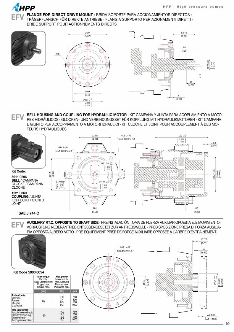
99
H P P › H i g h p r e s s u r e p u m p s
17.75[0.7]
22 max[0.87 max]
12[0.47]
Ø56
-0.0
1-0
.04
2.20
432.
2031
Ø40
[ 1.5
7]
M8 L=12M8 deep=0.47
17.75[0.7]
22 max[0.87 max]
12[0.47]
Ø56
-0.0
1-0
.04
2.20
432.
2031
Ø40
[ 1.5
7]
M8 L=12M8 deep=0.47
EFV
EFV
82.75[3.26]
Ø144[5.67]
Ø99[3.9]
80[3.15]
32[1.26]
8[0.31]
M12
M8
Ø117 +0.035-0
4.6084.606
Ø40
+0.0
18+0
.002
1.57
61.
575
FLANGE FOR DIRECT DRIVE MOUNT › BRIDA SOPORTE PARA ACCIONAMIENTOS DIRECTOS › TRÄGERFLANSCH FÜR DIREKTE ANTRIEBE › FLANGIA SUPPORTO PER AZIONAMENTI DIRETTI › BRIDE SUPPORT POUR ACTIONNEMENTS DIRECTS
BELL HOUSING AND COUPLING FOR HYDRAULIC MOTOR › KIT CAMPANA Y JUNTA PARA ACOPLAMIENTO A MOTO-RES HIDRÁULICOS › GLOCKEN- UND VERBINDUNGSSET FÜR KOPPLUNG MIT HYDRAULIKMOTOREN › KIT CAMPANA E GIUNTO PER ACCOPPIAMENTO A MOTORI IDRAULICI › KIT CLOCHE ET JOINT POUR ACCOUPLEMENT À DES MO-TEURS HYDRAULIQUES
114.5[4.51]
18.2[0.72]
114.
5[ 4
.51]
181[7.13]
85[3.35]
M14 L=34M14 deep=1.34
M16 L=39M16 deep=1.42
191 +0.05-0.05
7.5227.518
Ø31.75 +0.05+0.03
1.2521.251
Ø7.94 +0.156+0.07
0.3190.315
Ø12
7+0
.1+0
.05
5.00
45.
002
35.5
+0.0
2+0
1.40
61.
398
EFV AUXILIARY P.T.O. OPPOSITE TO SHAFT SIDE › PREINSTALACIÓN TOMA DE FUERZA AUXILIAR OPUESTA EJE MOVIMIENTO › VORRÜSTUNG NEBENANTRIEB ENTGEGENGESETZT ZUR ANTRIEBSWELLE › PREDISPOSIZIONE PRESA DI FORZA AUSILIA-RIA OPPOSTA ALBERO MOTO › PRÉ-ÉQUIPEMENT PRISE DE FORCE AUXILIAIRE OPPOSÉE À L’ARBRE D’ENTRAÎNEMENT.
Max torquePar máx.
Max. DrehmomentCoppia max.Couple max.
Max powerPotencia máx.Max. LeistungPotenza max.
Puissance max.[Nm] [Hp] rpm
Pulley/beltsCorreasRiemenCinghieCourroies
657,07,48,39,3
7508009001000
Flex joint directAcoplamiento directoDirekte VerbindungGiunto direttoAccouplement direct
13014,014,816,618,6
7508009001000
Kit Code 5003 0054
SAE J 744 C
Kit Code:5011 0296 BELL / CAMPANAGLOCKE / CAMPANACLOCHE1221 0060 COUPLING / JUNTAKOPPLUNG / GIUNTOJOINT
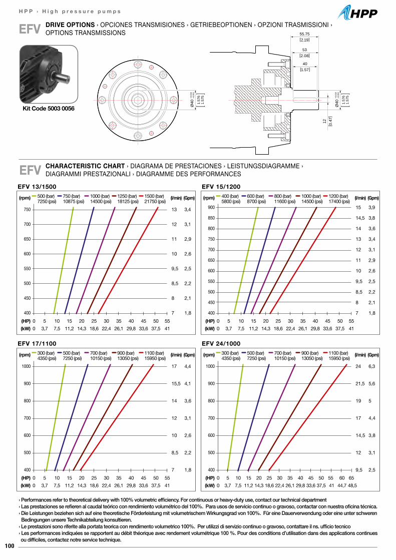
100
H P P › H i g h p r e s s u r e p u m p s
55.75[2.19]
12[ 0
.47]
53[2.08]
40[1.57]
Ø40
+0.0
18+0
.002
1.57
61.
575
Ø40
+0.0
18+0
.002
1.57
61.
575
CHARACTERISTIC CHART › DIAGRAMA DE PRESTACIONES › LEISTUNGSDIAGRAMME ›DIAGRAMMI PRESTAZIONALI › DIAGRAMME DES PERFORMANCESEFV
DRIVE OPTIONS › OPCIONES TRANSMISIONES › GETRIEBEOPTIONEN › OPZIONI TRASMISSIONI › OPTIONS TRANSMISSIONSEFV
Kit Code 5003 0056
› Performances refer to theoretical delivery with 100% volumetric efficiency. For continuous or heavy-duty use, contact our technical department› Las prestaciones se refieren al caudal teórico con rendimiento volumétrico del 100%. Para usos de servicio continuo o gravoso, contactar con nuestra oficina técnica.› Die Leistungen beziehen sich auf eine theoretische Förderleistung mit volumetrischem Wirkungsgrad von 100%. Für eine Dauerverwendung oder eine unter schweren Bedingungen unsere Technikabteilung konsultieren.› Le prestazioni sono riferite alla portata teorica con rendimento volumetrico 100%. Per utilizzi di servizio continuo o gravoso, contattare il ns. ufficio tecnico› Les performances indiquées se rapportent au débit théorique avec rendement volumétrique 100 %. Pour des conditions d’utilisation dans des applications continues ou difficiles, contactez notre service technique.
EFV 13/1500(l/min)
13
12
11
10
9,5
8,5
8
7
(Gpm)
3,4
3,1
2,9
2,6
2,5
2,2
2,1
1,8
500 (bar) 750 (bar) 1000 (bar) 1250 (bar) 1500 (bar)7250 (psi) 10875 (psi) 14500 (psi) 18125 (psi) 21750 (psi)
(HP) 0 5 10 15 20 25 30 35 40 45 50 55(kW) 0 3,7 7,5 11,2 14,3 18,6 22,4 26,1 29,8 33,6 37,5 41
(rpm)
750
700
650
600
550
500
450
400
EFV 17/1100300 (bar) 500 (bar) 700 (bar) 900 (bar) 1100 (bar)4350 (psi) 7250 (psi) 10150 (psi) 13050 (psi) 15950 (psi)
(HP) 0 5 10 15 20 25 30 35 40 45 50 55(kW) 0 3,7 7,5 11,2 14,3 18,6 22,4 26,1 29,8 33,6 37,5 41
(rpm)
1000
900
800
700
600
500
400
EFV 24/1000(l/min)
24
21,5
19
17
14,5
12
9,5
300 (bar) 500 (bar) 700 (bar) 900 (bar) 1100 (bar)4350 (psi) 7250 (psi) 10150 (psi) 13050 (psi) 15950 (psi)
(HP) 0 5 10 15 20 25 30 35 40 45 50 55 60 65(kW) 0 3,7 7,5 11,2 14,3 18,6 22,4 26,1 29,8 33,6 37,5 41 44,7 48,5
(rpm)
1000
900
800
700
600
500
400
EFV 15/1200(l/min)
15
14,5
14
13
12
11
10
9,5
8,5
8
7
(Gpm)
3,9
3,8
3,6
3,4
3,1
2,9
2,6
2,5
2,2
2,1
1,8
400 (bar) 600 (bar) 800 (bar) 1000 (bar) 1200 (bar)5800 (psi) 8700 (psi) 11600 (psi) 14500 (psi) 17400 (psi)
(HP) 0 5 10 15 20 25 30 35 40 45 50 55(kW) 0 3,7 7,5 11,2 14,3 18,6 22,4 26,1 29,8 33,6 37,5 41
(rpm)
900
850
800
750
700
650
600
550
500
450
400
(Gpm)
6,3
5,6
5
4,4
3,8
3,1
2,5
(Gpm)
4,4
4,1
3,6
3,1
2,6
2,2
1,8
(l/min)
17
15,5
14
12
10
8,5
7
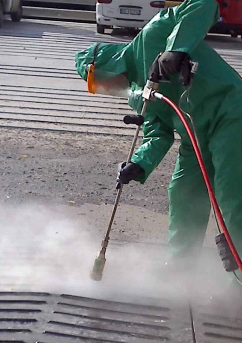
101
H P P › H i g h p r e s s u r e p u m p s
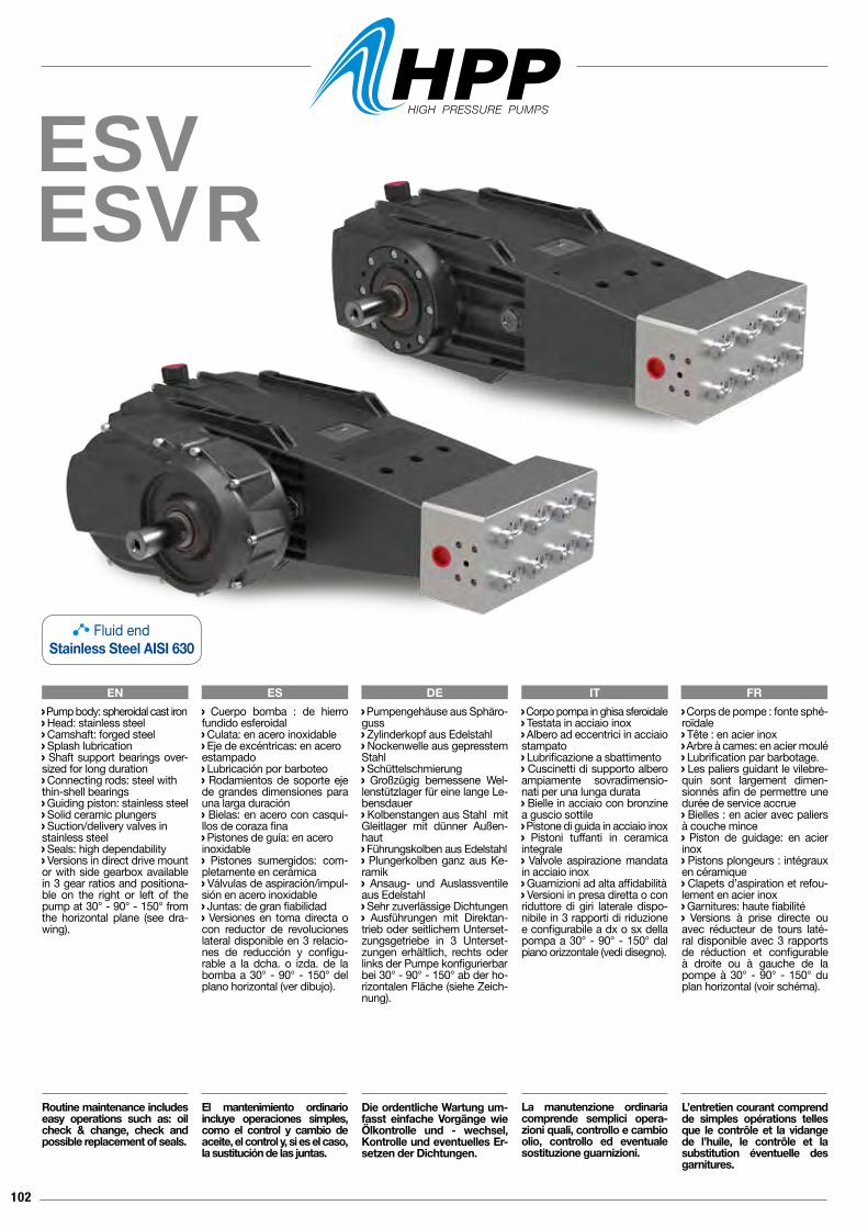
102
ESVESVR
EN ES DE IT FR Corpo pompa in ghisa sferoidale Testata in acciaio inox Albero ad eccentrici in acciaio stampato Lubrificazione a sbattimento Cuscinetti di supporto albero ampiamente sovradimensio-nati per una lunga durata Bielle in acciaio con bronzine a guscio sottile Pistone di guida in acciaio inox Pistoni tuffanti in ceramica integrale Valvole aspirazione mandata in acciaio inox Guarnizioni ad alta affidabilità Versioni in presa diretta o con riduttore di giri laterale dispo-nibile in 3 rapporti di riduzione e configurabile a dx o sx della pompa a 30° - 90° - 150° dal piano orizzontale (vedi disegno).
La manutenzione ordinaria comprende semplici opera-zioni quali, controllo e cambio olio, controllo ed eventuale sostituzione guarnizioni.
Pump body: spheroidal cast iron Head: stainless steel Camshaft: forged steel Splash lubrication Shaft support bearings over-sized for long duration Connecting rods: steel withthin-shell bearings Guiding piston: stainless steel Solid ceramic plungers Suction/delivery valves instainless steel Seals: high dependability Versions in direct drive mount or with side gearbox available in 3 gear ratios and positiona-ble on the right or left of the pump at 30° - 90° - 150° from the horizontal plane (see dra-wing).
Routine maintenance includes easy operations such as: oil check & change, check and possible replacement of seals.
Cuerpo bomba : de hierro fundido esferoidal Culata: en acero inoxidable Eje de excéntricas: en aceroestampado Lubricación por barboteo Rodamientos de soporte eje de grandes dimensiones para una larga duración Bielas: en acero con casqui-llos de coraza fina Pistones de guía: en aceroinoxidable Pistones sumergidos: com-pletamente en cerámica Válvulas de aspiración/impul-sión en acero inoxidable Juntas: de gran fiabilidad Versiones en toma directa o con reductor de revoluciones lateral disponible en 3 relacio-nes de reducción y configu-rable a la dcha. o izda. de la bomba a 30° - 90° - 150° del plano horizontal (ver dibujo).
El mantenimiento ordinario incluye operaciones simples, como el control y cambio de aceite, el control y, si es el caso, la sustitución de las juntas.
Pumpengehäuse aus Sphäro-guss Zylinderkopf aus Edelstahl Nockenwelle aus gepresstem Stahl Schüttelschmierung Großzügig bemessene Wel-lenstützlager für eine lange Le-bensdauer Kolbenstangen aus Stahl mit Gleitlager mit dünner Außen-haut Führungskolben aus Edelstahl Plungerkolben ganz aus Ke-ramik Ansaug- und Auslassventile aus Edelstahl Sehr zuverlässige Dichtungen Ausführungen mit Direktan-trieb oder seitlichem Unterset-zungsgetriebe in 3 Unterset-zungen erhältlich, rechts oder links der Pumpe konfigurierbarbei 30° - 90° - 150° ab der ho-rizontalen Fläche (siehe Zeich-nung).
Die ordentliche Wartung um-fasst einfache Vorgänge wie Ölkontrolle und - wechsel, Kontrolle und eventuelles Er-setzen der Dichtungen.
Corps de pompe : fonte sphé-roïdale Tête : en acier inox Arbre à cames: en acier moulé Lubrification par barbotage. Les paliers guidant le vilebre-quin sont largement dimen-sionnés afin de permettre une durée de service accrue Bielles : en acier avec paliers à couche mince Piston de guidage: en acier inox Pistons plongeurs : intégraux en céramique Clapets d’aspiration et refou-lement en acier inox Garnitures: haute fiabilité Versions à prise directe ou avec réducteur de tours laté-ral disponible avec 3 rapports de réduction et configurable à droite ou à gauche de la pompe à 30° - 90° - 150° du plan horizontal (voir schéma).
L’entretien courant comprend de simples opérations telles que le contrôle et la vidange de l’huile, le contrôle et la substitution éventuelle des garnitures.
Fluid endStainless Steel AISI 630
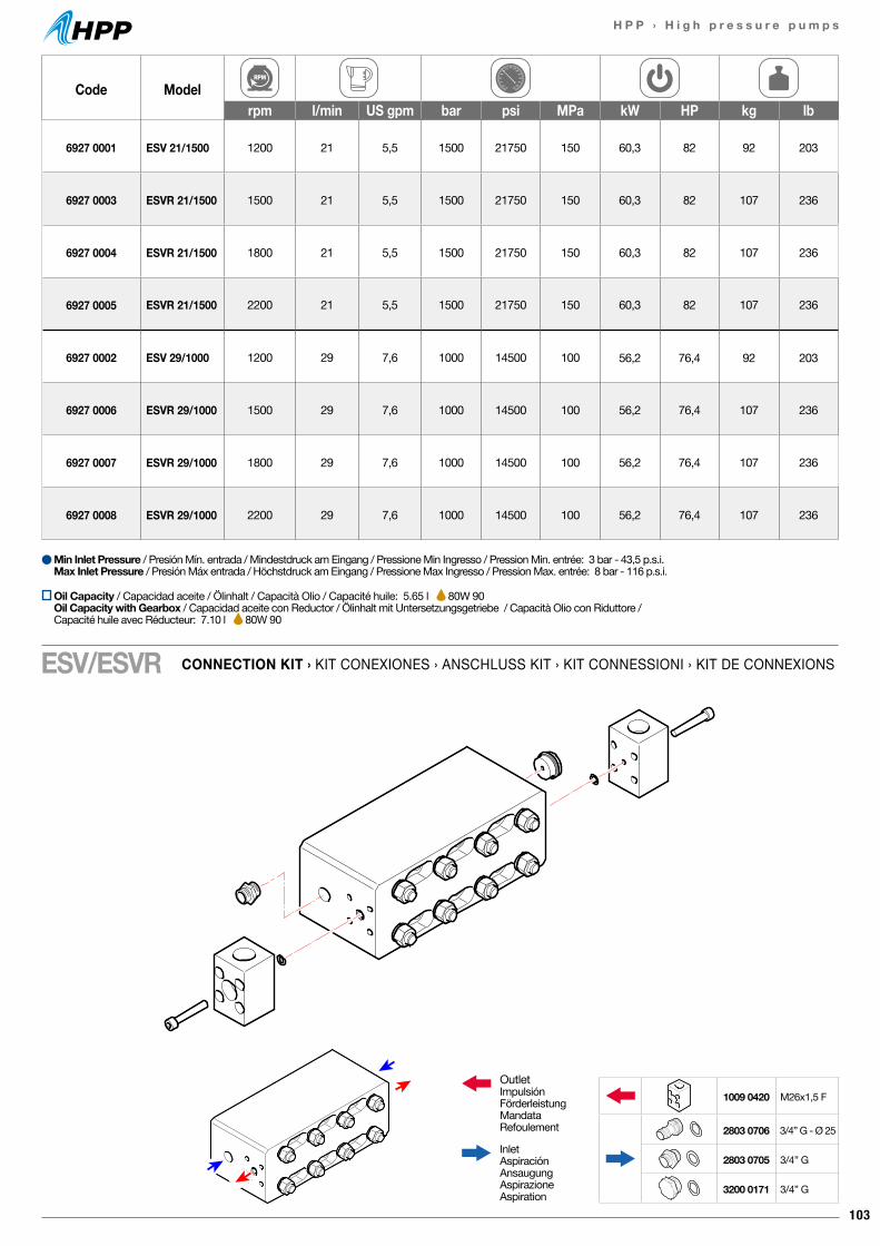
103
H P P › H i g h p r e s s u r e p u m p s
Code Modelrpm l/min US gpm bar psi MPa kW HP kg lb
6927 0001 ESV 21/1500 1200 21 5,5 1500 21750 150 60,3 82 92 203
6927 0003 ESVR 21/1500 1500 21 5,5 1500 21750 150 60,3 82 107 236
6927 0004 ESVR 21/1500 1800 21 5,5 1500 21750 150 60,3 82 107 236
6927 0005 ESVR 21/1500 2200 21 5,5 1500 21750 150 60,3 82 107 236
6927 0002 ESV 29/1000 1200 29 7,6 1000 14500 100 56,2 76,4 92 203
6927 0006 ESVR 29/1000 1500 29 7,6 1000 14500 100 56,2 76,4 107 236
6927 0007 ESVR 29/1000 1800 29 7,6 1000 14500 100 56,2 76,4 107 236
6927 0008 ESVR 29/1000 2200 29 7,6 1000 14500 100 56,2 76,4 107 236
Min Inlet Pressure / Presión Mín. entrada / Mindestdruck am Eingang / Pressione Min Ingresso / Pression Min. entrée: 3 bar - 43,5 p.s.i.Max Inlet Pressure / Presión Máx entrada / Höchstdruck am Eingang / Pressione Max Ingresso / Pression Max. entrée: 8 bar - 116 p.s.i.
CONNECTION KIT › KIT CONEXIONES › ANSCHLUSS KIT › KIT CONNESSIONI › KIT DE CONNEXIONSESV/ESVR
OutletImpulsiónFörderleistungMandataRefoulement
InletAspiraciónAnsaugungAspirazioneAspiration
1009 0420 M26x1,5 F
2803 0706 3/4” G - Ø 25
2803 0705 3/4” G
3200 0171 3/4” G
Oil Capacity / Capacidad aceite / Ölinhalt / Capacità Olio / Capacité huile: 5.65 l 80W 90Oil Capacity with Gearbox / Capacidad aceite con Reductor / Ölinhalt mit Untersetzungsgetriebe / Capacità Olio con Riduttore / Capacité huile avec Réducteur: 7.10 l 80W 90
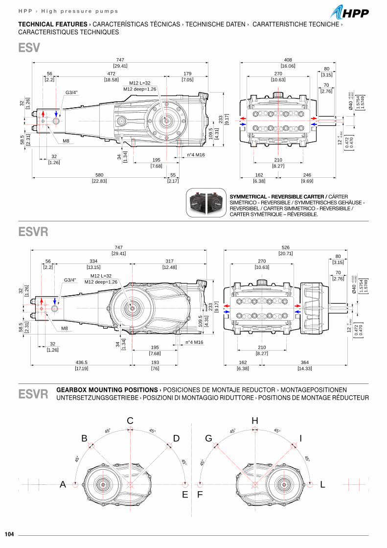
104
H P P › H i g h p r e s s u r e p u m p s
45° 45°
45° 45°
A
B
C
D
E
45°45°
45°
45°
L
I
H
G
F
270[10.63]
80[3.15]
70[2.76]
210[8.27]
162[6.38]
Ø40
+0.0
15+0
.002
1.57
541.
5749
0.47
20.
470
12-0 -0
.052
747[29.41]
56[2.2]
233
[ 9.1
7]
109.
5[ 4
.31]
195[7.68]
32[1.26]
32[ 1
.26]
58.5
[ 2.3
1]
G3/4"
M8
M12 L=32M12 deep=1.26
526[20.71]
364[14.33]
n°4 M16
34[ 1
.34]
317[12.48]
334[13.15]
436.5[17.19]
193[76]
408[16.06]
270[10.63]
80[3.15]
70[2.76]
210[8.27]
246[9.69]
162[6.38]
Ø40
+0.0
15+0
.002
1.57
541.
5749
0.47
20.
470
12-0 -0
.052
747[29.41]
472[18.58]
56[2.2]
179[7.05]
233
[ 9.1
7]
109.
5[ 4
.31]
195[7.68]
580[22.83]
55[2.17]
32[1.26]
32[ 1
.26]
n°4 M16
58.5
[ 2.3
1]
G3/4"
M8
M12 L=32M12 deep=1.26
34[ 1
.34]
GEARBOX MOUNTING POSITIONS › POSICIONES DE MONTAJE REDUCTOR › MONTAGEPOSITIONEN UNTERSETZUNGSGETRIEBE › POSIZIONI DI MONTAGGIO RIDUTTORE › POSITIONS DE MONTAGE RÉDUCTEUR
TECHNICAL FEATURES › CARACTERÍSTICAS TÉCNICAS › TECHNISCHE DATEN › CARATTERISTICHE TECNICHE ›CARACTERISTIQUES TECHNIQUES
ESV
ESVR
SYMMETRICAL - REVERSIBLE CARTER / CÁRTER SIMÉTRICO - REVERSIBLE / SYMMETRISCHES GEHÄUSE - REVERSIBEL / CARTER SIMMETRICO - REVERSIBILE / CARTER SYMÉTRIQUE – RÉVERSIBLE.
ESVR
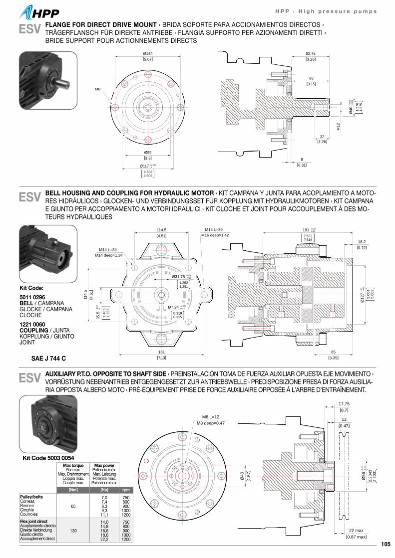
105
H P P › H i g h p r e s s u r e p u m p s
17.75[0.7]
22 max[0.87 max]
12[0.47]
Ø56
-0.0
1-0
.04
2.20
432.
2031
Ø40
[ 1.5
7]
M8 L=12M8 deep=0.47
17.75[0.7]
22 max[0.87 max]
12[0.47]
Ø56
-0.0
1-0
.04
2.20
432.
2031
Ø40
[ 1.5
7]
M8 L=12M8 deep=0.47
ESV
ESV
ESV
Kit Code 5003 0054Max torque
Par máx.Max. Drehmoment
Coppia max.Couple max.
Max powerPotencia máx.Max. LeistungPotenza max.
Puissance max.[Nm] [Hp] rpm
Pulley/beltsCorreasRiemenCinghieCourroies
65
7,07,48,39,311,1
75080090010001200
Flex joint directAcoplamiento directoDirekte VerbindungGiunto direttoAccouplement direct
130
14,014,816,618,622,2
75080090010001200
82.75[3.26]
Ø144[5.67]
Ø99[3.9]
80[3.15]
32[1.26]
8[0.31]
M12
M8
Ø117 +0.035-0
4.6084.606
Ø40
+0.0
18+0
.002
1.57
61.
575
114.5[4.51]
18.2[0.72]
114.
5[ 4
.51]
181[7.13]
85[3.35]
M14 L=34M14 deep=1.34
M16 L=39M16 deep=1.42
191 +0.05-0.05
7.5227.518
Ø31.75 +0.05+0.03
1.2521.251
Ø7.94 +0.156+0.07
0.3190.315
Ø12
7+0
.1+0
.05
5.00
45.
002
35.5
+0.0
2+0
1.40
61.
398
FLANGE FOR DIRECT DRIVE MOUNT › BRIDA SOPORTE PARA ACCIONAMIENTOS DIRECTOS › TRÄGERFLANSCH FÜR DIREKTE ANTRIEBE › FLANGIA SUPPORTO PER AZIONAMENTI DIRETTI › BRIDE SUPPORT POUR ACTIONNEMENTS DIRECTS
BELL HOUSING AND COUPLING FOR HYDRAULIC MOTOR › KIT CAMPANA Y JUNTA PARA ACOPLAMIENTO A MOTO-RES HIDRÁULICOS › GLOCKEN- UND VERBINDUNGSSET FÜR KOPPLUNG MIT HYDRAULIKMOTOREN › KIT CAMPANA E GIUNTO PER ACCOPPIAMENTO A MOTORI IDRAULICI › KIT CLOCHE ET JOINT POUR ACCOUPLEMENT À DES MO-TEURS HYDRAULIQUES
AUXILIARY P.T.O. OPPOSITE TO SHAFT SIDE › PREINSTALACIÓN TOMA DE FUERZA AUXILIAR OPUESTA EJE MOVIMIENTO › VORRÜSTUNG NEBENANTRIEB ENTGEGENGESETZT ZUR ANTRIEBSWELLE › PREDISPOSIZIONE PRESA DI FORZA AUSILIA-RIA OPPOSTA ALBERO MOTO › PRÉ-ÉQUIPEMENT PRISE DE FORCE AUXILIAIRE OPPOSÉE À L’ARBRE D’ENTRAÎNEMENT.
SAE J 744 C
Kit Code:5011 0296 BELL / CAMPANAGLOCKE / CAMPANACLOCHE1221 0060 COUPLING / JUNTAKOPPLUNG / GIUNTOJOINT
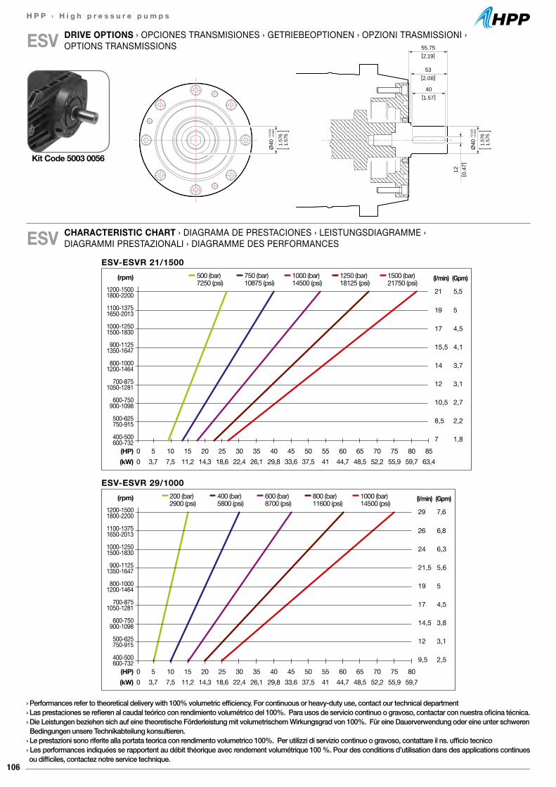
106
H P P › H i g h p r e s s u r e p u m p s
DRIVE OPTIONS › OPCIONES TRANSMISIONES › GETRIEBEOPTIONEN › OPZIONI TRASMISSIONI › OPTIONS TRANSMISSIONSESV 55.75
[2.19]
12[ 0
.47]
53[2.08]
40[1.57]
Ø40
+0.0
18+0
.002
1.57
61.
575
Ø40
+0.0
18+0
.002
1.57
61.
575
CHARACTERISTIC CHART › DIAGRAMA DE PRESTACIONES › LEISTUNGSDIAGRAMME ›DIAGRAMMI PRESTAZIONALI › DIAGRAMME DES PERFORMANCESESV
Kit Code 5003 0056
› Performances refer to theoretical delivery with 100% volumetric efficiency. For continuous or heavy-duty use, contact our technical department› Las prestaciones se refieren al caudal teórico con rendimiento volumétrico del 100%. Para usos de servicio continuo o gravoso, contactar con nuestra oficina técnica.› Die Leistungen beziehen sich auf eine theoretische Förderleistung mit volumetrischem Wirkungsgrad von 100%. Für eine Dauerverwendung oder eine unter schweren Bedingungen unsere Technikabteilung konsultieren.› Le prestazioni sono riferite alla portata teorica con rendimento volumetrico 100%. Per utilizzi di servizio continuo o gravoso, contattare il ns. ufficio tecnico› Les performances indiquées se rapportent au débit théorique avec rendement volumétrique 100 %. Pour des conditions d’utilisation dans des applications continues ou difficiles, contactez notre service technique.
ESV-ESVR 29/1000(l/min)
29
26
24
21,5
19
17
14,5
12
9,5
(Gpm)
7,6
6,8
6,3
5,6
5
4,5
3,8
3,1
2,5
200 (bar) 400 (bar) 600 (bar) 800 (bar) 1000 (bar)2900 (psi) 5800 (psi) 8700 (psi) 11600 (psi) 14500 (psi)
(HP) 0 5 10 15 20 25 30 35 40 45 50 55 60 65 70 75 80(kW) 0 3,7 7,5 11,2 14,3 18,6 22,4 26,1 29,8 33,6 37,5 41 44,7 48,5 52,2 55,9 59,7
(rpm)1200-15001800-2200
1100-13751650-2013
1000-12501500-1830
900-11251350-1647
800-10001200-1464
700-8751050-1281
600-750900-1098
500-625750-915
400-500600-732
ESV-ESVR 21/1500500 (bar) 750 (bar) 1000 (bar) 1250 (bar) 1500 (bar)7250 (psi) 10875 (psi) 14500 (psi) 18125 (psi) 21750 (psi)
(HP) 0 5 10 15 20 25 30 35 40 45 50 55 60 65 70 75 80 85(kW) 0 3,7 7,5 11,2 14,3 18,6 22,4 26,1 29,8 33,6 37,5 41 44,7 48,5 52,2 55,9 59,7 63,4
(l/min)
21
19
17
15,5
14
12
10,5
8,5
7
(Gpm)
5,5
5
4,5
4,1
3,7
3,1
2,7
2,2
1,8
(rpm)1200-15001800-2200
1100-13751650-2013
1000-12501500-1830
900-11251350-1647
800-10001200-1464
700-8751050-1281
600-750900-1098
500-625750-915
400-500600-732
107
H P P › H i g h p r e s s u r e p u m p s
108

109
H P P › H i g h p r e s s u r e p u m p s
AccessoriesAccessoriosZubehörAccessoriAccessoires
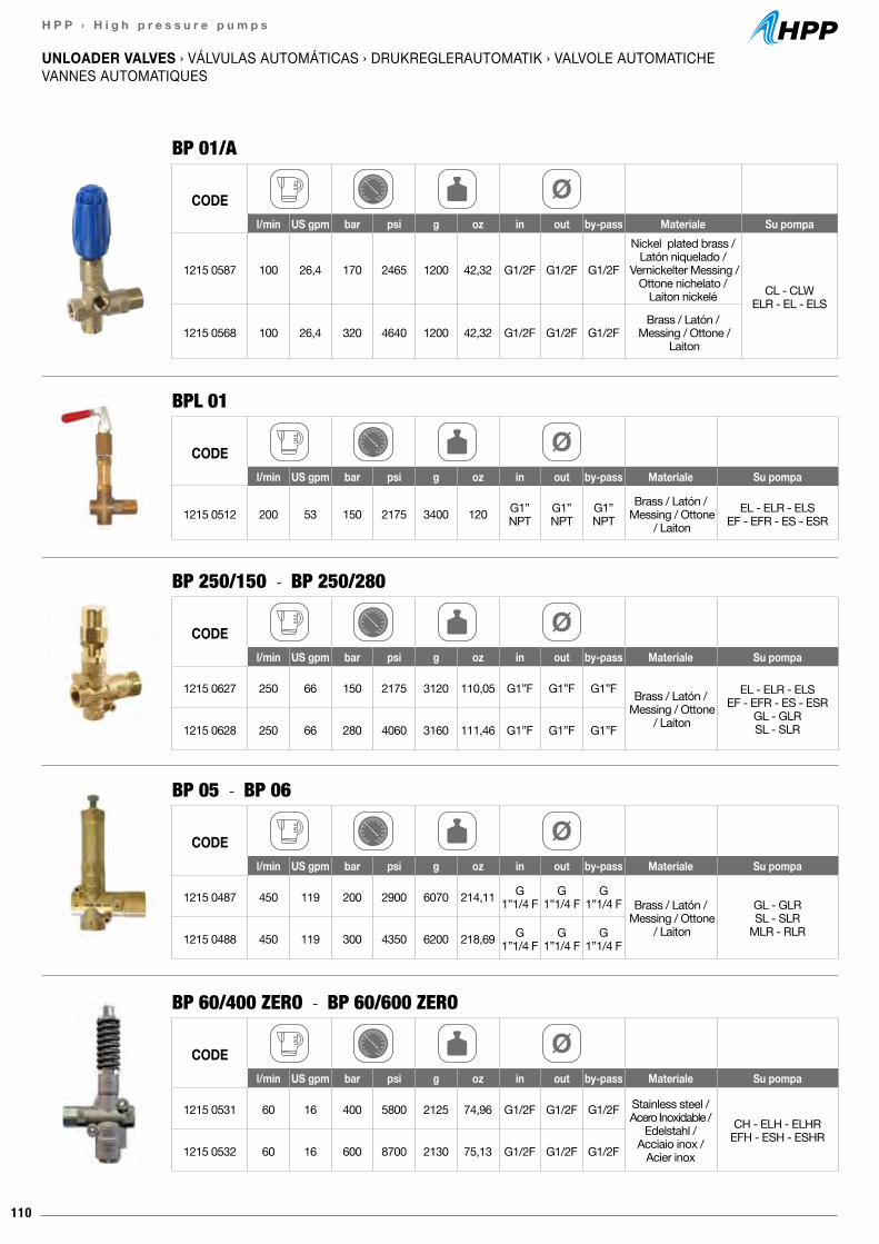
110
H P P › H i g h p r e s s u r e p u m p s
BP 60/400 ZERO - BP 60/600 ZERO
CODEl/min US gpm bar psi g oz in out by-pass Materiale Su pompa
1215 0531 60 16 400 5800 2125 74,96 G1/2F G1/2F G1/2F Stainless steel / Acero Inoxidable /
Edelstahl / Acciaio inox /
Acier inox
CH - ELH - ELHREFH - ESH - ESHR
1215 0532 60 16 600 8700 2130 75,13 G1/2F G1/2F G1/2F
UNLOADER VALVES › VÁLVULAS AUTOMÁTICAS › DRUKREGLERAUTOMATIK › VALVOLE AUTOMATICHEVANNES AUTOMATIQUES
CODEl/min US gpm bar psi g oz in out by-pass Materiale Su pompa
1215 0587 100 26,4 170 2465 1200 42,32 G1/2F G1/2F G1/2F
Nickel plated brass / Latón niquelado /
Vernickelter Messing /Ottone nichelato /
Laiton nickelé CL - CLWELR - EL - ELS
1215 0568 100 26,4 320 4640 1200 42,32 G1/2F G1/2F G1/2FBrass / Latón /
Messing / Ottone / Laiton
BP 01/A
CODEl/min US gpm bar psi g oz in out by-pass Materiale Su pompa
1215 0512 200 53 150 2175 3400 120 G1”NPT
G1”NPT
G1”NPT
Brass / Latón / Messing / Ottone
/ LaitonEL - ELR - ELS
EF - EFR - ES - ESR
BPL 01
BP 250/150 - BP 250/280
BP 05 - BP 06
CODEl/min US gpm bar psi g oz in out by-pass Materiale Su pompa
1215 0627 250 66 150 2175 3120 110,05 G1”F G1”F G1”F Brass / Latón / Messing / Ottone
/ Laiton
EL - ELR - ELSEF - EFR - ES - ESR
GL - GLRSL - SLR1215 0628 250 66 280 4060 3160 111,46 G1”F G1”F G1”F
CODEl/min US gpm bar psi g oz in out by-pass Materiale Su pompa
1215 0487 450 119 200 2900 6070 214,11 G1”1/4 F
G1”1/4 F
G1”1/4 F Brass / Latón /
Messing / Ottone / Laiton
GL - GLRSL - SLR
MLR - RLR1215 0488 450 119 300 4350 6200 218,69 G1”1/4 F
G1”1/4 F
G1”1/4 F
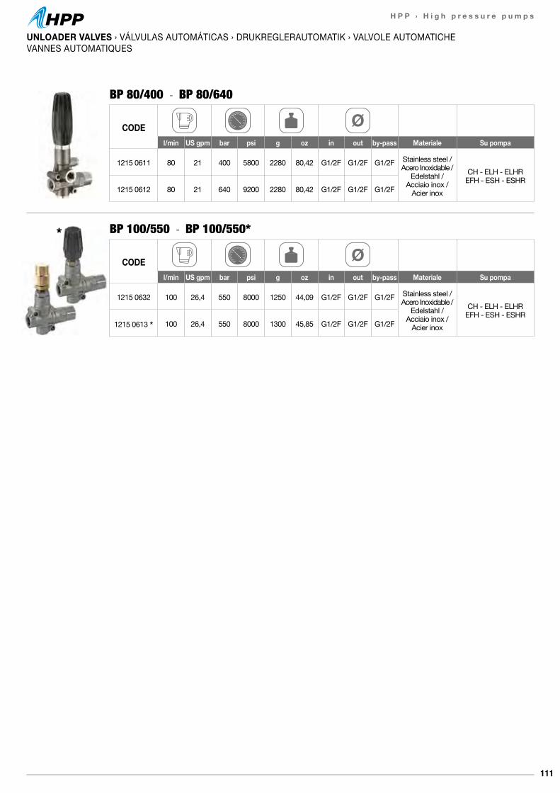
111
H P P › H i g h p r e s s u r e p u m p s
UNLOADER VALVES › VÁLVULAS AUTOMÁTICAS › DRUKREGLERAUTOMATIK › VALVOLE AUTOMATICHEVANNES AUTOMATIQUES
BP 100/550 - BP 100/550*
CODEl/min US gpm bar psi g oz in out by-pass Materiale Su pompa
1215 0632 100 26,4 550 8000 1250 44,09 G1/2F G1/2F G1/2F Stainless steel / Acero Inoxidable /
Edelstahl / Acciaio inox /
Acier inox
CH - ELH - ELHREFH - ESH - ESHR
1215 0613 * 100 26,4 550 8000 1300 45,85 G1/2F G1/2F G1/2F
BP 80/400 - BP 80/640
CODEl/min US gpm bar psi g oz in out by-pass Materiale Su pompa
1215 0611 80 21 400 5800 2280 80,42 G1/2F G1/2F G1/2F Stainless steel / Acero Inoxidable /
Edelstahl / Acciaio inox /
Acier inox
CH - ELH - ELHREFH - ESH - ESHR
1215 0612 80 21 640 9200 2280 80,42 G1/2F G1/2F G1/2F
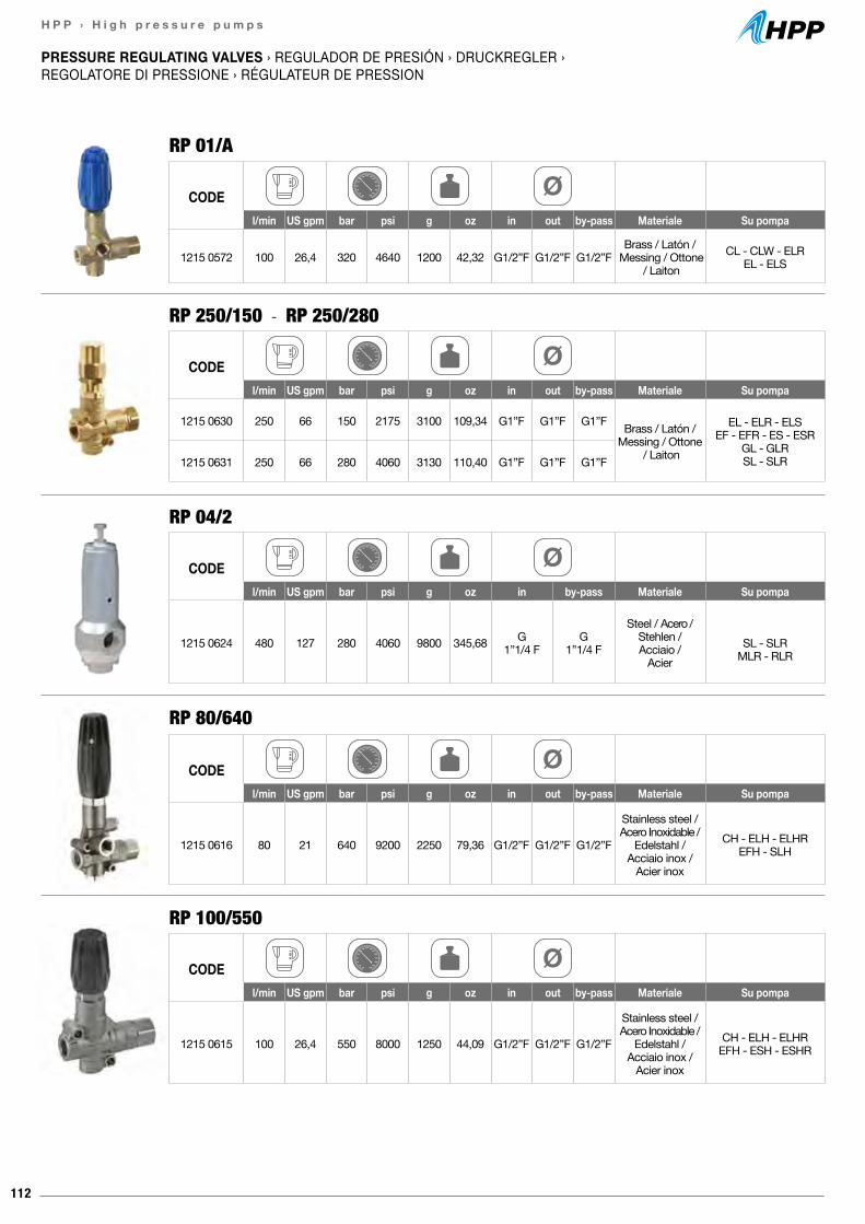
112
H P P › H i g h p r e s s u r e p u m p s
PRESSURE REGULATING VALVES › REGULADOR DE PRESIÓN › DRUCKREGLER › REGOLATORE DI PRESSIONE › RÉGULATEUR DE PRESSION
RP 01/A
RP 80/640
RP 250/150 - RP 250/280
RP 04/2
RP 100/550
CODEl/min US gpm bar psi g oz in out by-pass Materiale Su pompa
1215 0572 100 26,4 320 4640 1200 42,32 G1/2”F G1/2”F G1/2”FBrass / Latón /
Messing / Ottone / Laiton
CL - CLW - ELREL - ELS
CODEl/min US gpm bar psi g oz in out by-pass Materiale Su pompa
1215 0630 250 66 150 2175 3100 109,34 G1”F G1”F G1”F Brass / Latón /Messing / Ottone
/ Laiton
EL - ELR - ELSEF - EFR - ES - ESR
GL - GLRSL - SLR1215 0631 250 66 280 4060 3130 110,40 G1”F G1”F G1”F
CODEl/min US gpm bar psi g oz in by-pass Materiale Su pompa
1215 0624 480 127 280 4060 9800 345,68 G 1”1/4 F
G 1”1/4 F
Steel / Acero / Stehlen / Acciaio /
AcierSL - SLR
MLR - RLR
CODEl/min US gpm bar psi g oz in out by-pass Materiale Su pompa
1215 0615 100 26,4 550 8000 1250 44,09 G1/2”F G1/2”F G1/2”F
Stainless steel / Acero Inoxidable /
Edelstahl / Acciaio inox /
Acier inox
CH - ELH - ELHREFH - ESH - ESHR
CODEl/min US gpm bar psi g oz in out by-pass Materiale Su pompa
1215 0616 80 21 640 9200 2250 79,36 G1/2”F G1/2”F G1/2”F
Stainless steel / Acero Inoxidable /
Edelstahl / Acciaio inox /
Acier inox
CH - ELH - ELHREFH - SLH
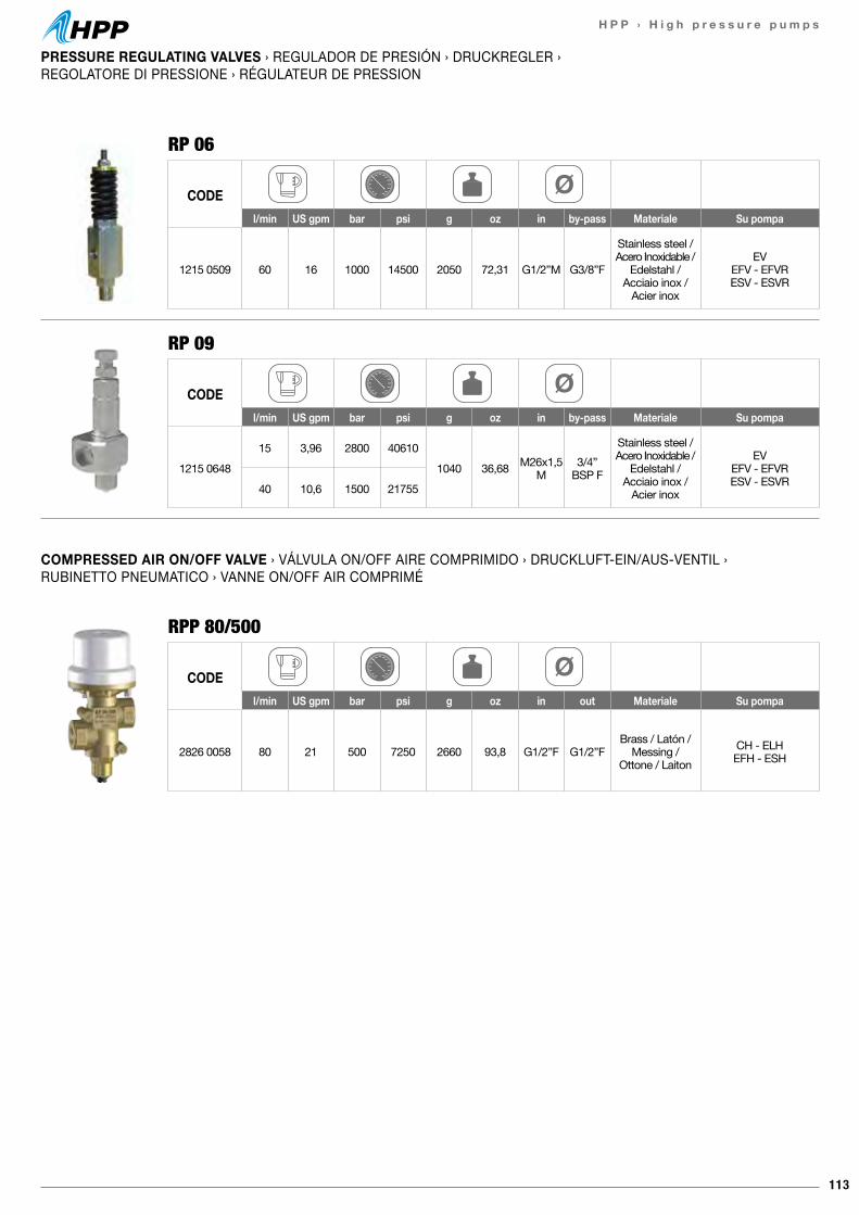
113
H P P › H i g h p r e s s u r e p u m p s
PRESSURE REGULATING VALVES › REGULADOR DE PRESIÓN › DRUCKREGLER › REGOLATORE DI PRESSIONE › RÉGULATEUR DE PRESSION
COMPRESSED AIR ON/OFF VALVE › VÁLVULA ON/OFF AIRE COMPRIMIDO › DRUCKLUFT-EIN/AUS-VENTIL › RUBINETTO PNEUMATICO › VANNE ON/OFF AIR COMPRIMÉ
RP 06
RPP 80/500
RP 09
CODEl/min US gpm bar psi g oz in by-pass Materiale Su pompa
1215 0509 60 16 1000 14500 2050 72,31 G1/2”M G3/8”F
Stainless steel / Acero Inoxidable /
Edelstahl / Acciaio inox /
Acier inox
EVEFV - EFVRESV - ESVR
CODEl/min US gpm bar psi g oz in out Materiale Su pompa
2826 0058 80 21 500 7250 2660 93,8 G1/2”F G1/2”FBrass / Latón /
Messing / Ottone / Laiton
CH - ELHEFH - ESH
CODEl/min US gpm bar psi g oz in by-pass Materiale Su pompa
1215 064815 3,96 2800 40610
1040 36,68 M26x1,5M
3/4” BSP F
Stainless steel / Acero Inoxidable /
Edelstahl / Acciaio inox /
Acier inox
EVEFV - EFVRESV - ESVR40 10,6 1500 21755
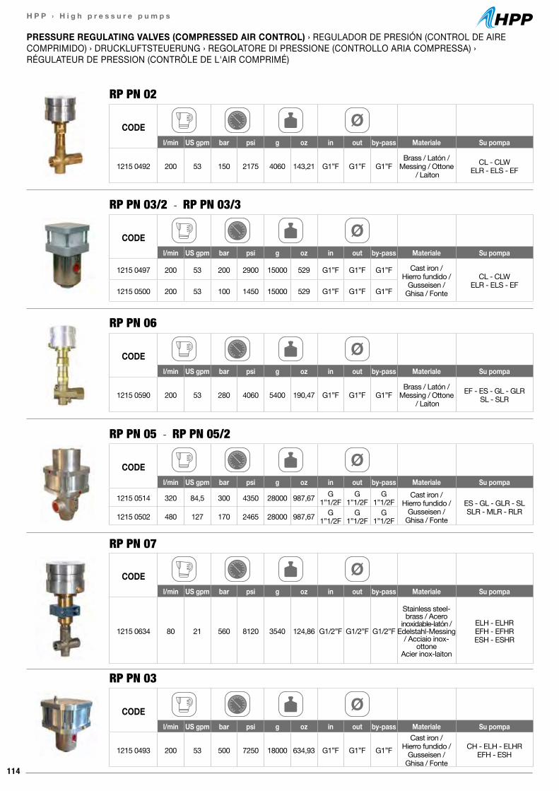
114
H P P › H i g h p r e s s u r e p u m p s
PRESSURE REGULATING VALVES (COMPRESSED AIR CONTROL) › REGULADOR DE PRESIÓN (CONTROL DE AIRE COMPRIMIDO) › DRUCKLUFTSTEUERUNG › REGOLATORE DI PRESSIONE (CONTROLLO ARIA COMPRESSA) ›RÉGULATEUR DE PRESSION (CONTRÔLE DE L'AIR COMPRIMÉ)
RP PN 02
RP PN 03
RP PN 03/2 - RP PN 03/3
RP PN 05 - RP PN 05/2
CODEl/min US gpm bar psi g oz in out by-pass Materiale Su pompa
1215 0492 200 53 150 2175 4060 143,21 G1”F G1”F G1”FBrass / Latón /
Messing / Ottone / Laiton
CL - CLWELR - ELS - EF
CODEl/min US gpm bar psi g oz in out by-pass Materiale Su pompa
1215 0590 200 53 280 4060 5400 190,47 G1”F G1”F G1”FBrass / Latón /
Messing / Ottone / Laiton
EF - ES - GL - GLRSL - SLR
CODEl/min US gpm bar psi g oz in out by-pass Materiale Su pompa
1215 0493 200 53 500 7250 18000 634,93 G1”F G1”F G1”FCast iron /
Hierro fundido / Gusseisen /
Ghisa / Fonte
CH - ELH - ELHREFH - ESH
CODEl/min US gpm bar psi g oz in out by-pass Materiale Su pompa
1215 0497 200 53 200 2900 15000 529 G1”F G1”F G1”F Cast iron / Hierro fundido /
Gusseisen / Ghisa / Fonte
CL - CLWELR - ELS - EF
1215 0500 200 53 100 1450 15000 529 G1”F G1”F G1”F
CODEl/min US gpm bar psi g oz in out by-pass Materiale Su pompa
1215 0514 320 84,5 300 4350 28000 987,67 G1”1/2F
G1”1/2F
G1”1/2F
Cast iron / Hierro fundido /
Gusseisen / Ghisa / Fonte
ES - GL - GLR - SLSLR - MLR - RLR1215 0502 480 127 170 2465 28000 987,67 G
1”1/2FG
1”1/2FG
1”1/2F
RP PN 06
RP PN 07
CODEl/min US gpm bar psi g oz in out by-pass Materiale Su pompa
1215 0634 80 21 560 8120 3540 124,86 G1/2”F G1/2”F G1/2”F
Stainless steel-brass / Acero
inoxidable-latón / Edelstahl-Messing
/ Acciaio inox-ottone
Acier inox-laiton
ELH - ELHREFH - EFHRESH - ESHR
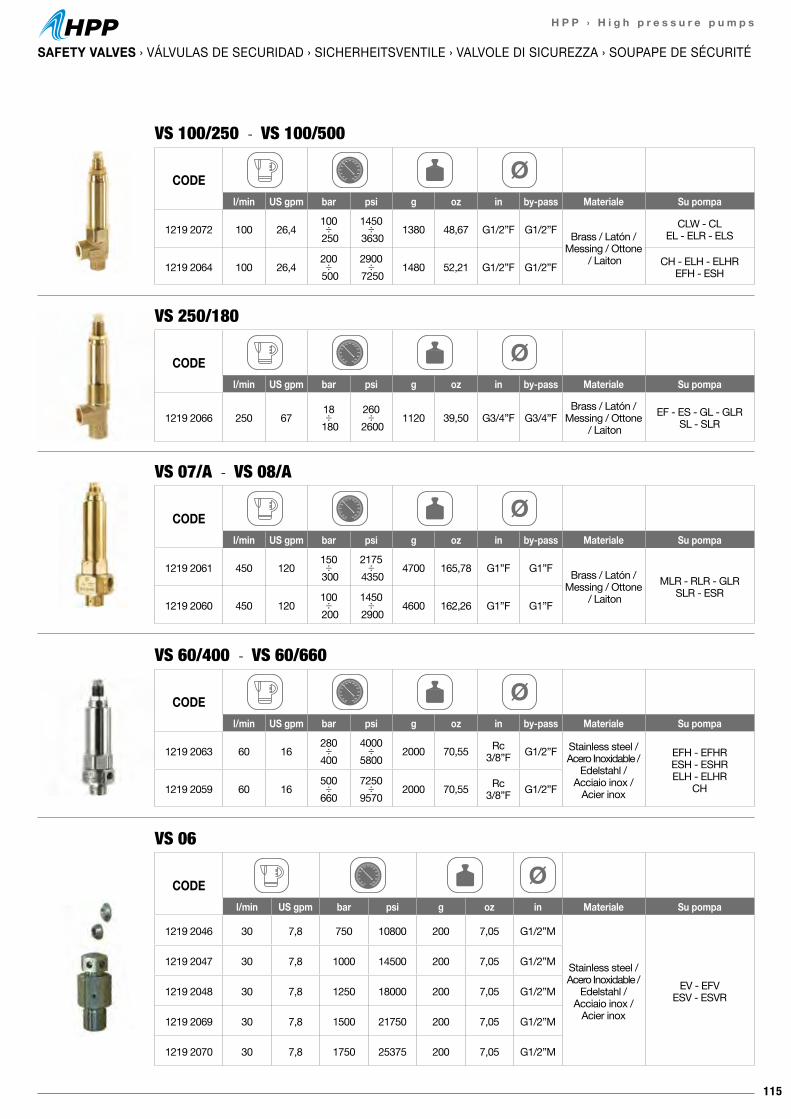
115
H P P › H i g h p r e s s u r e p u m p s
SAFETY VALVES › VÁLVULAS DE SECURIDAD › SICHERHEITSVENTILE › VALVOLE DI SICUREZZA › SOUPAPE DE SÉCURITÉ
VS 250/180
VS 100/250 - VS 100/500
VS 06
CODEl/min US gpm bar psi g oz in by-pass Materiale Su pompa
1219 2066 250 6718 ÷
180260 ÷
26001120 39,50 G3/4”F G3/4”F
Brass / Latón /Messing / Ottone
/ LaitonEF - ES - GL - GLR
SL - SLR
CODEl/min US gpm bar psi g oz in by-pass Materiale Su pompa
1219 2072 100 26,4100 ÷ 250
1450 ÷ 3630
1380 48,67 G1/2”F G1/2”F Brass / Latón /Messing / Ottone
/ Laiton
CLW - CLEL - ELR - ELS
1219 2064 100 26,4200 ÷ 500
2900 ÷ 7250
1480 52,21 G1/2”F G1/2”F CH - ELH - ELHREFH - ESH
VS 60/400 - VS 60/660
CODEl/min US gpm bar psi g oz in by-pass Materiale Su pompa
1219 2063 60 16280 ÷400
4000 ÷5800
2000 70,55 Rc3/8”F G1/2”F Stainless steel /
Acero Inoxidable / Edelstahl /
Acciaio inox /Acier inox
EFH - EFHRESH - ESHRELH - ELHR
CH1219 2059 60 16500 ÷660
7250 ÷9570
2000 70,55 Rc3/8”F G1/2”F
CODEl/min US gpm bar psi g oz in Materiale Su pompa
1219 2046 30 7,8 750 10800 200 7,05 G1/2”M
Stainless steel / Acero Inoxidable /
Edelstahl / Acciaio inox /
Acier inox
EV - EFVESV - ESVR
1219 2047 30 7,8 1000 14500 200 7,05 G1/2”M
1219 2048 30 7,8 1250 18000 200 7,05 G1/2”M
1219 2069 30 7,8 1500 21750 200 7,05 G1/2”M
1219 2070 30 7,8 1750 25375 200 7,05 G1/2”M
VS 07/A - VS 08/A
CODEl/min US gpm bar psi g oz in by-pass Materiale Su pompa
1219 2061 450 120150 ÷ 300
2175 ÷ 4350
4700 165,78 G1”F G1”F Brass / Latón /Messing / Ottone
/ LaitonMLR - RLR - GLR
SLR - ESR1219 2060 450 120
100 ÷ 200
1450 ÷ 2900
4600 162,26 G1”F G1”F

116
H P P › H i g h p r e s s u r e p u m p s
PRESSURE GAUGES › MANÓMETROS › MANOMETER › MANOMETRI › MANOMÈTRES
MA 01 - 02 - 03 - 04 - 05
MA 06 - 07 - 08 - 09 - 10
CODE DN63 Accuracy classClasse di precisione
bar psi g oz connection
1816 0140 0-250 0-3625 210 7,40 G1/4”B 1,6
1816 0141 0-315 0-4570 210 7,40 G1/4”B 1,6
1816 0142 0-400 0-5800 210 7,40 G1/4”B 1,6
1816 0143 0-600 0-8700 210 7,40 G1/4”B 1,6
1816 0144 0-1000 0-14500 210 7,40 G1/4”B 1,6
CODE DN100 Accuracy classClasse di precisione
bar psi g oz connection
1816 0145 0-600 0-8700 830 29,27 G1/2”B 1,0
1816 0146 0-1000 0-14500 830 29,27 G1/2”B 1,0
1816 0147 0-1600 0-23200 830 29,27 G1/2”B 1,0
1816 0161 0-2500 0-36250 830 29,27 G1/2”B 1,0
1816 0162 0-4000 0-58000 1100 38,80 M16x1,5 F 1,0
FOOT VALVE › VALVULA DE PEDAL › FUßVENTIL › VALVOLA A PEDALE › VANNE À PÉDALE
VP 01
CODEl/min US gpm bar psi g oz in out
0608 0056 60 16 1050 15000 5090 179,54 G1/2”M G1/2”M
VP 80/500
CODEl/min US gpm bar psi g oz in out
0608 0106 80 21 500 7250 7350 259,26 G1/2”F G1/2”F
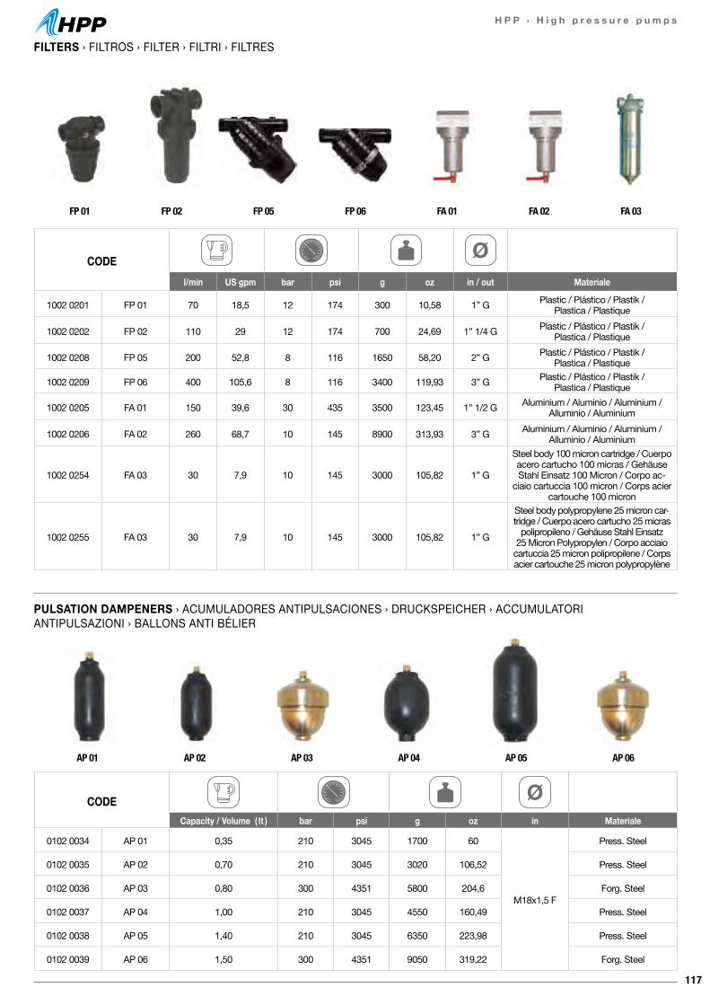
117
H P P › H i g h p r e s s u r e p u m p s
FILTERS › FILTROS › FILTER › FILTRI › FILTRES
PULSATION DAMPENERS › ACUMULADORES ANTIPULSACIONES › DRUCKSPEICHER › ACCUMULATORI ANTIPULSAZIONI › BALLONS ANTI BÉLIER
CODEl/min US gpm bar psi g oz in / out Materiale
1002 0201 FP 01 70 18,5 12 174 300 10,58 1” G Plastic / Plástico / Plastik / Plastica / Plastique
1002 0202 FP 02 110 29 12 174 700 24,69 1” 1/4 G Plastic / Plástico / Plastik / Plastica / Plastique
1002 0208 FP 05 200 52,8 8 116 1650 58,20 2” G Plastic / Plástico / Plastik / Plastica / Plastique
1002 0209 FP 06 400 105,6 8 116 3400 119,93 3” G Plastic / Plástico / Plastik / Plastica / Plastique
1002 0205 FA 01 150 39,6 30 435 3500 123,45 1” 1/2 G Aluminium / Aluminio / Aluminium / Alluminio / Aluminium
1002 0206 FA 02 260 68,7 10 145 8900 313,93 3” G Aluminium / Aluminio / Aluminium / Alluminio / Aluminium
1002 0254 FA 03 30 7,9 10 145 3000 105,82 1” G
Steel body 100 micron cartridge / Cuerpo acero cartucho 100 micras / Gehäuse Stahl Einsatz 100 Micron / Corpo ac-
ciaio cartuccia 100 micron / Corps acier cartouche 100 micron
1002 0255 FA 03 30 7,9 10 145 3000 105,82 1” G
Steel body polypropylene 25 micron car-tridge / Cuerpo acero cartucho 25 micras
polipropileno / Gehäuse Stahl Einsatz 25 Micron Polypropylen / Corpo acciaio
cartuccia 25 micron polipropilene / Corps acier cartouche 25 micron polypropylène
FP 01 FP 02 FP 05 FP 06 FA 01 FA 02 FA 03
CODECapacity / Volume ( lt ) bar psi g oz in Materiale
0102 0034 AP 01 0,35 210 3045 1700 60
M18x1,5 F
Press. Steel
0102 0035 AP 02 0,70 210 3045 3020 106,52 Press. Steel
0102 0036 AP 03 0,80 300 4351 5800 204,6 Forg. Steel
0102 0037 AP 04 1,00 210 3045 4550 160,49 Press. Steel
0102 0038 AP 05 1,40 210 3045 6350 223,98 Press. Steel
0102 0039 AP 06 1,50 300 4351 9050 319,22 Forg. Steel
AP 01 AP 02 AP 03 AP 04 AP 05 AP 06
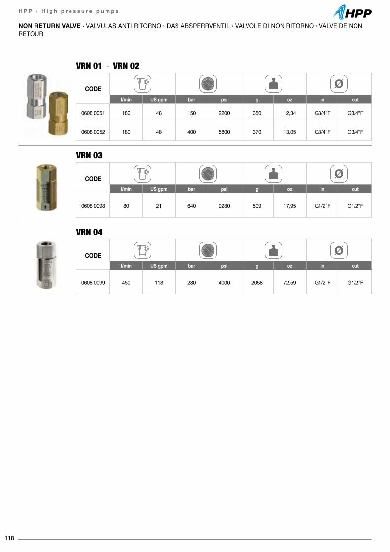
118
H P P › H i g h p r e s s u r e p u m p s
NON RETURN VALVE › VÁLVULAS ANTI RITORNO › DAS ABSPERRVENTIL › VALVOLE DI NON RITORNO › VALVE DE NON RETOUR
VRN 01 - VRN 02
CODEl/min US gpm bar psi g oz in out
0608 0051 180 48 150 2200 350 12,34 G3/4”F G3/4”F
0608 0052 180 48 400 5800 370 13,05 G3/4”F G3/4”F
VRN 04
CODEl/min US gpm bar psi g oz in out
0608 0099 450 118 280 4000 2058 72,59 G1/2”F G1/2”F
VRN 03
CODEl/min US gpm bar psi g oz in out
0608 0098 80 21 640 9280 509 17,95 G1/2”F G1/2”F
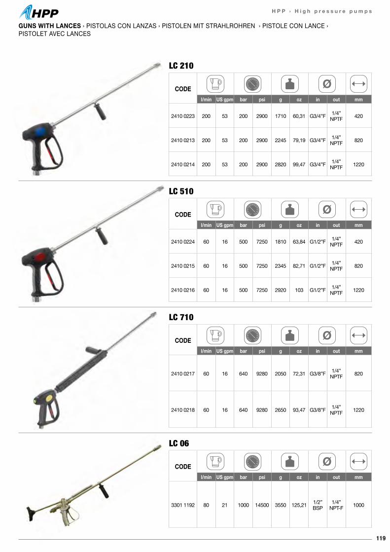
119
H P P › H i g h p r e s s u r e p u m p s
GUNS WITH LANCES › PISTOLAS CON LANZAS › PISTOLEN MIT STRAHLROHREN › PISTOLE CON LANCE › PISTOLET AVEC LANCES
CODEl/min US gpm bar psi g oz in out mm
2410 0223 200 53 200 2900 1710 60,31 G3/4”F 1/4”NPTF 420
2410 0213 200 53 200 2900 2245 79,19 G3/4”F 1/4”NPTF 820
2410 0214 200 53 200 2900 2820 99,47 G3/4”F 1/4”NPTF 1220
CODEl/min US gpm bar psi g oz in out mm
2410 0224 60 16 500 7250 1810 63,84 G1/2”F 1/4”NPTF 420
2410 0215 60 16 500 7250 2345 82,71 G1/2”F 1/4”NPTF 820
2410 0216 60 16 500 7250 2920 103 G1/2”F 1/4”NPTF 1220
CODEl/min US gpm bar psi g oz in out mm
2410 0217 60 16 640 9280 2050 72,31 G3/8”F 1/4”NPTF 820
2410 0218 60 16 640 9280 2650 93,47 G3/8”F 1/4”NPTF 1220
CODEl/min US gpm bar psi g oz in out mm
3301 1192 80 21 1000 14500 3550 125,21 1/2”BSP
1/4”NPT-F 1000
LC 210
LC 510
LC 710
LC 06

120
H P P › H i g h p r e s s u r e p u m p s
NOTE

121
H P P › H i g h p r e s s u r e p u m p s
NOTE
122
H P P › H i g h p r e s s u r e p u m p s
The specificaTions, dimensional drawings and picTures are indicaTive only and noT binding , comeT reserves The righT To make changes wiThouT prior noTice.
las especificaciones, los dibujos Técnicos y las imágenes son a TíTulo indicaTivo y no vincu-lanTes; comeT se reserva el derecho de aporTar modificaciones sin previo aviso.
die wiedergegebenen daTen, Zeichnungen und abbildungen sind nichT bindend, sondern sTellen richTwerTe dar und die firma comeT behälT sich das rechT vor, ohne jede vorankündigung änderungen vorZunehmen.
le specifiche, i dimensionali e le immagini sono indicaTive e non vincolanTi; comeT si riserva di apporTare modifiche senZa preavviso.
les spécificaTions, les dessins de dimensions eT les images sonT indicaTives eT non conTrai-gnantes ; Comet se réserve d’apporter des modifiCations sans préavis.

123
H P P › H i g h p r e s s u r e p u m p s
1610
129
2 00
E
Follow us on
DownloadComet Spa
App
Comet Spa › via G. Dorso, 4 - 42124 Reggio Emilia › Italy › phone + 39 0522 386111 › www.hpp-pressurepumps.comItalia: [email protected] › Fax + 39 0522 386300Export: [email protected] › Fax + 39 0522 386280
Distributed by: / Distribuito da:P.T.C. Srl › via Mantegna, 4 - 42048 Rubiera (RE) - Italy
Phone: +39 0522/1932911 › Fax: +39 0522/1932922mail: [email protected] › website: www.ptcitaliana.com