TEC Series Wireless Thermostat Controller System Technical Bulletin
Upload
truongduongCategory
view
219download
0
XLR SERIESXLR-600-SL, XLR-1000-SL, XLR-1400-SL, XLR-1600-4
INSTRUCTION MANUAL
Distributing, L.L.C.
472 South Mill Street, Alamo TN 38001Sales: 800-851-8180 - Sales Fax: 618-993-5960http://www.southernpride.com - [email protected] - [email protected]: 800-437-2679 - Service Fax: 618-993-0378 - [email protected]
2
CONGRATULATIONS
In selecting Southern Pride, you have chosen the finest, most advancedand most fully automatic wood burning barbecue pit available.
With us, “ It’s Simply, a Matter of Pride”.
Please read this Instruction Manual carefully prior to installation and operationof your Southern Pride pit. Proper installation, operation, cleaning and maintenance
are essential for your satisfaction and safe operation.
KEEP THIS MANNUAL FOR REFERENCE
TABLE OF CONTENTS
Safety Information . . . . . . . . . . . . . . . . . . . . . . . . . . . . . . . . . . . . . . . . . . . 3
Diagram of Controls & Components . . . . . . . . . . . . . . . . . . . . . . . . . . . . 4
Operating Instructions Manual Controls . . . . . . . . . . . . . . . . . . . . . .. . . 6
Operating Instructions Digital Controls . . . . . . . . . . . . . . . . . . . . . .. . . 8
Cold Weather Operations . . . . . . . . . . . . . . . . . . . . . . . . . . . . . . . . . . . . 10
Cleaning Instructions . . . . . . . . . . . . . . . . . . . . . . . . . . . . . . . . . . . . . . . . 11
Maintenance Schedule . . . . . . . . . . . . . . . . . . . . . . . . . . . . . . . . . . . . . . . 12
Electrical Instructions . . . . . . . . . . . . . . . . . . . . . . . . . . . . . . . . . . . . . . . 14
Burner Specification & Instructions . . . . . . . . . . . . . . . . . . . . . . . . . . . . 18
Venting Instructions . . . . . . . . . . . . . . . . . . . . . . . . . . . . . . . . . . . . . . . . . 20
Replacement Parts List . . . . . . . . . . . . . . . . . . . . . . . . . . . . . . . . . . . . . . . 23
Warranty . . . . . . . . . . . . . . . . . . . . . . . . . . . . . . . . . . . . . . . . . . . . . . . . . . 24
FOR YOUR SAFETY
IF YOU SMELL GAS . . .1. Open windows.
2. Do not touch electrical switches. 3. Extinguish any open flames. 4. Immediately call your gas supplier.
DO NOT STORE OR USE GASOLINE OR OTHER FLAMMABLE VAPORS ORLIQUIDS IN THE VICINITY OF THIS OR ANY OTHER APPLIANCES.
SAFETY INFORMATION
1. The pit area MUST be kept clear and free of combustible materials, gasoline and other flammable vapors and liquids.
2. The flow of combustion and ventilating air MUST NOT be obstructed from reaching the pit.
3. The frame of the unit MUST be electrically grounded at all times. See “Electrical Instructions”.
4. Caution should be used when opening and closing the Firebox Door. The door is HOTduring operation.
5. DO NOT remove service compartment access panels when unit is in operation or leave off during operation.
6. Gas burners require the services of an experienced Service Technician for proper setting and adjustment. If the burner does not appear to be operating properly, DO NOT ATTEMPT TO ADJUST THE BURNER YOURSELF, but call in a competent serviceman or contact Southern Pride.
7. DO NOT allow unqualified personnel to perform service work or adjustments on this unit. To do so will VOID WARRANTY and could result in a hazardous condition.
8. Be sure any new employees, who might operate the unit, are instructed on operation and safety information prior to operating the unit.
9. Caution: Ashes removed from the Firebox should be stored in a non-combustible container with a sealed lid only. Store ashes in a well ventilated area. FUMES COULD BE HAZARDOUS.
10. WARNING: IT IS EXTREMELY IMPORTANT TO FOLLOW DAILY CLEANING INSTRUCTIONS. BUILDUP OF GREASE OR SOLIDS INSIDE THE PIT COULD RESULT IN A FIRE HAZARD.
11. KEEP THIS INSTRUCTION MANUAL FOR REFERENCE.
3
OFF ON
M
AIN P O W E
R
RO
TI
SSERIE ADVANCE
SM
O
KE EXTRACTOR
CIR
C
UIT B REAK
ER
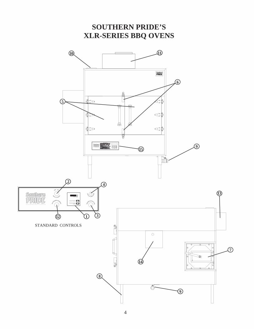
SOUTHERN PRIDE’SXLR-SERIES BBQ OVENS
4
10 11
15
6
9
5
13
14
7
8
112
42
STANDARD CONTROLS
3
9
COOKTEMP
HOLDTEMP
COOKTIME UP
DOWNSTARTSTOP
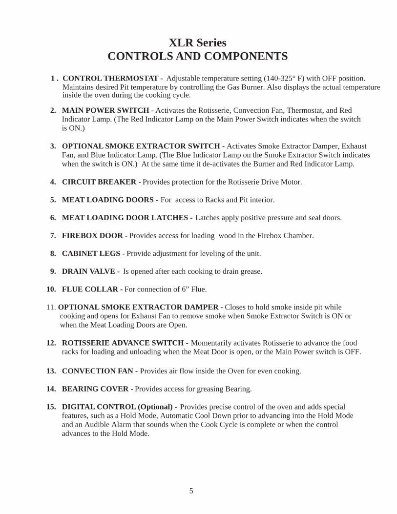
XLR SeriesCONTROLS AND COMPONENTS
1 . CONTROL THERMOSTAT - Adjustable temperature setting (140-325° F) with OFF position. Maintains desired Pit temperature by controlling the Gas Burner. Also displays the actual temperature inside the oven during the cooking cycle.
2. MAIN POWER SWITCH - Activates the Rotisserie, Convection Fan, Thermostat, and Red Indicator Lamp. (The Red Indicator Lamp on the Main Power Switch indicates when the switch is ON.)
3. OPTIONAL SMOKE EXTRACTOR SWITCH - Activates Smoke Extractor Damper, Exhaust Fan, and Blue Indicator Lamp. (The Blue Indicator Lamp on the Smoke Extractor Switch indicates when the switch is ON.) At the same time it de-activates the Burner and Red Indicator Lamp.
4. CIRCUIT BREAKER - Provides protection for the Rotisserie Drive Motor.
5. MEAT LOADING DOORS - For access to Racks and Pit interior.
6. MEAT LOADING DOOR LATCHES - Latches apply positive pressure and seal doors.
7. FIREBOX DOOR - Provides access for loading wood in the Firebox Chamber.
8. CABINET LEGS - Provide adjustment for leveling of the unit.
9. DRAIN VALVE - Is opened after each cooking to drain grease.
10. FLUE COLLAR - For connection of 6” Flue.
11. OPTIONAL SMOKE EXTRACTOR DAMPER - Closes to hold smoke inside pit while cooking and opens for Exhaust Fan to remove smoke when Smoke Extractor Switch is ON or when the Meat Loading Doors are Open.
12. ROTISSERIE ADVANCE SWITCH - Momentarily activates Rotisserie to advance the food racks for loading and unloading when the Meat Door is open, or the Main Power switch is OFF.
13. CONVECTION FAN - Provides air flow inside the Oven for even cooking.
14. BEARING COVER - Provides access for greasing Bearing.
15. DIGITAL CONTROL (Optional) - Provides precise control of the oven and adds special features, such as a Hold Mode, Automatic Cool Down prior to advancing into the Hold Mode and an Audible Alarm that sounds when the Cook Cycle is complete or when the control advances to the Hold Mode.
5
OPERATING INSTRUCTIONSFOR MANUAL CONTROLS
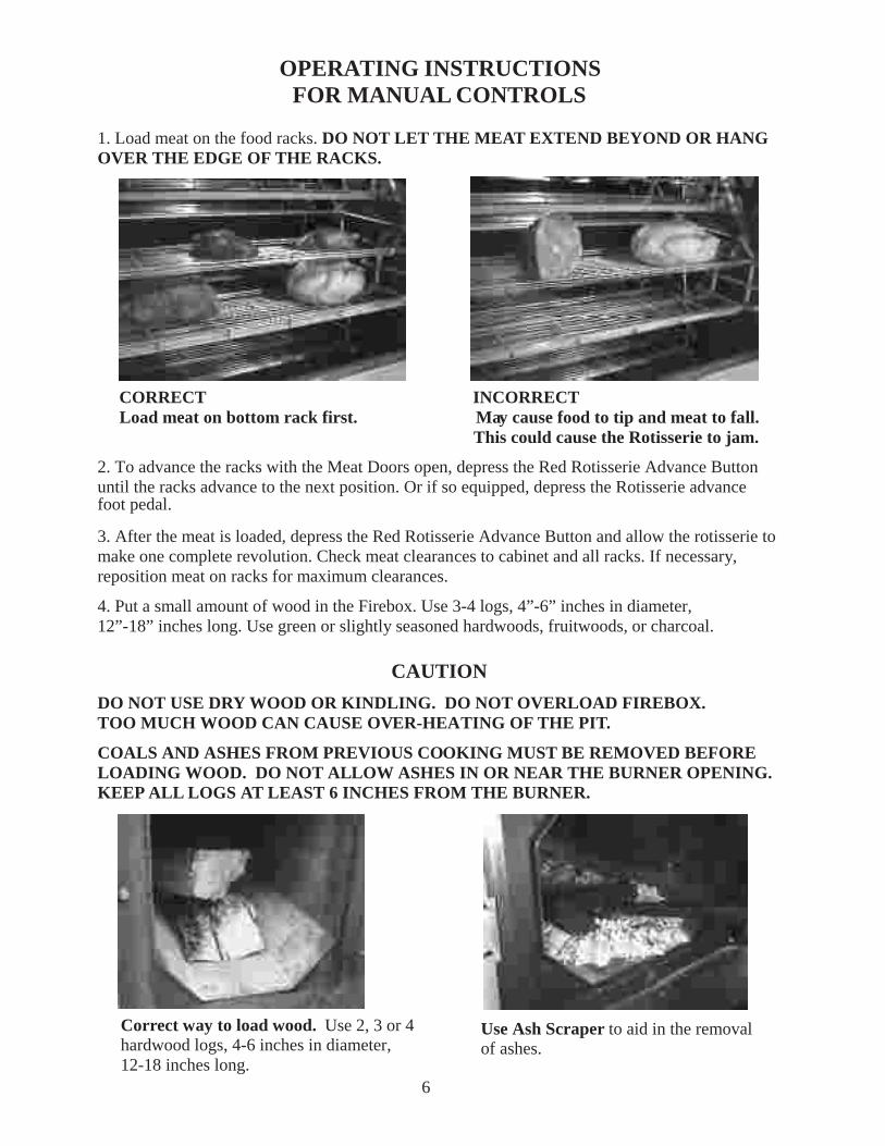
1. Load meat on the food racks. DO NOT LET THE MEAT EXTEND BEYOND OR HANGOVER THE EDGE OF THE RACKS.
CORRECT INCORRECT Load meat on bottom rack first. May cause food to tip and meat to fall. This could cause the Rotisserie to jam.
2. To advance the racks with the Meat Doors open, depress the Red Rotisserie Advance Buttonuntil the racks advance to the next position. Or if so equipped, depress the Rotisserie advancefoot pedal.
3. After the meat is loaded, depress the Red Rotisserie Advance Button and allow the rotisserie tomake one complete revolution. Check meat clearances to cabinet and all racks. If necessary,reposition meat on racks for maximum clearances.
4. Put a small amount of wood in the Firebox. Use 3-4 logs, 4”-6” inches in diameter,12”-18” inches long. Use green or slightly seasoned hardwoods, fruitwoods, or charcoal.
CAUTION
DO NOT USE DRY WOOD OR KINDLING. DO NOT OVERLOAD FIREBOX.TOO MUCH WOOD CAN CAUSE OVER-HEATING OF THE PIT.
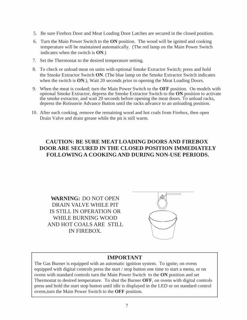
COALS AND ASHES FROM PREVIOUS COOKING MUST BE REMOVED BEFORELOADING WOOD. DO NOT ALLOW ASHES IN OR NEAR THE BURNER OPENING.KEEP ALL LOGS AT LEAST 6 INCHES FROM THE BURNER.
Use Ash Scraper to aid in the removalof ashes.
Correct way to load wood. Use 2, 3 or 4hardwood logs, 4-6 inches in diameter,12-18 inches long.
6
5. Be sure Firebox Door and Meat Loading Door Latches are secured in the closed position.
7. Set the Thermostat to the desired temperature setting.
6. Turn the Main Power Switch to the ON position. The wood will be ignited and cooking temperature will be maintained automatically. (The red lamp on the Main Power Switch indicates when the switch is ON.)
7
8. To check or unload meat on units with optional Smoke Extractor Switch; press and hold the Smoke Extractor Switch ON. (The blue lamp on the Smoke Extractor Switch indicates when the switch is ON.), Wait 20 seconds prior to opening the Meat Loading Doors.
9. When the meat is cooked; turn the Main Power Switch to the OFF position. On models with optional Smoke Extractor, depress the Smoke Extractor Switch to the ON position to activate the smoke extractor, and wait 20 seconds before opening the meat doors. To unload racks, depress the Rotisserie Advance Button until the racks advance to an unloading position.
10. After each cooking, remove the remaining wood and hot coals from Firebox, then open Drain Valve and drain grease while the pit is still warm.
CAUTION: BE SURE MEAT LOADING DOORS AND FIREBOX DOOR ARE SECURED IN THE CLOSED POSITION IMMEDIATELY
FOLLOWING A COOKING AND DURING NON-USE PERIODS.
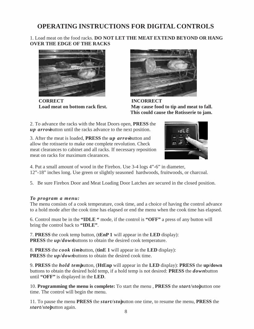
WARNING: DO NOT OPENDRAIN VALVE WHILE PIT
IS STILL IN OPERATION ORWHILE BURNING WOOD
AND HOT COALS ARE STILLIN FIREBOX.
IMPORTANT The Gas Burner is equipped with an automatic ignition system. To ignite; on ovens equipped with digital controls press the start / stop button one time to start a menu, or on ovens with standard controls turn the Main Power Switch to the ON position and set Thermostat to desired temperature. To shut the Burner OFF, on ovens with digital controls press and hold the start stop button until idle is displayed in the LED or on standard control ovens,turn the Main Power Switch to the OFF position.
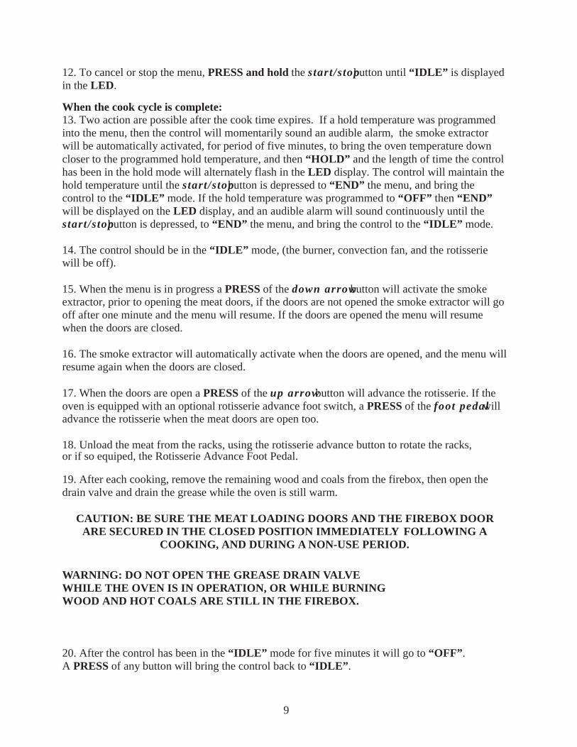
1. Load meat on the food racks. DO NOT LET THE MEAT EXTEND BEYOND OR HANGOVER THE EDGE OF THE RACKS
CORRECT INCORRECT Load meat on bottom rack first. May cause food to tip and meat to fall. This could cause the Rotisserie to jam.
2. To advance the racks with the Meat Doors open, PRESS theup arrow button until the racks advance to the next position.
3. After the meat is loaded, PRESS the up arrow button andallow the rotisserie to make one complete revolution. Checkmeat clearances to cabinet and all racks. If necessary repositionmeat on racks for maximum clearances.
4. Put a small amount of wood in the Firebox. Use 3-4 logs 4”-6” in diameter,12”-18” inches long. Use green or slightly seasoned hardwoods, fruitwoods, or charcoal.
5. Be sure Firebox Door and Meat Loading Door Latches are secured in the closed position.
To program a menu:The menu consists of a cook temperature, cook time, and a choice of having the control advanceto a hold mode after the cook time has elapsed or end the menu when the cook time has elapsed.
6. Control must be in the “IDLE “ mode, if the control is “OFF” a press of any button willbring the control back to “IDLE”.
7. PRESS the cook temp button, (tEnP 1 will appear in the LED display):PRESS the up/down buttons to obtain the desired cook temperature.
8. PRESS the cook time button, (tinE 1 will appear in the LED display):PRESS the up/down buttons to obtain the desired cook time.
9. PRESS the hold temp button, (HtEnp will appear in the LED display): PRESS the up/downbuttons to obtain the desired hold temp, if a hold temp is not desired: PRESS the down buttonuntil “OFF” is displayed in the LED.
10. Programming the menu is complete: To start the menu , PRESS the start/stop button onetime. The control will begin the menu.
11. To pause the menu PRESS the start/stop button one time, to resume the menu, PRESS thestart/stop button again.
OPERATING INSTRUCTIONS FOR DIGITAL CONTROLS
8
9
12. To cancel or stop the menu, PRESS and hold the start/stop button until “IDLE” is displayedin the LED.
When the cook cycle is complete:13. Two action are possible after the cook time expires. If a hold temperature was programmedinto the menu, then the control will momentarily sound an audible alarm, the smoke extractorwill be automatically activated, for period of five minutes, to bring the oven temperature downcloser to the programmed hold temperature, and then “HOLD” and the length of time the controlhas been in the hold mode will alternately flash in the LED display. The control will maintain thehold temperature until the start/stop button is depressed to “END” the menu, and bring thecontrol to the “IDLE” mode. If the hold temperature was programmed to “OFF” then “END”will be displayed on the LED display, and an audible alarm will sound continuously until thestart/stop button is depressed, to “END” the menu, and bring the control to the “IDLE” mode.
14. The control should be in the “IDLE” mode, (the burner, convection fan, and the rotisseriewill be off).
15. When the menu is in progress a PRESS of the down arrow button will activate the smokeextractor, prior to opening the meat doors, if the doors are not opened the smoke extractor will gooff after one minute and the menu will resume. If the doors are opened the menu will resumewhen the doors are closed.
16. The smoke extractor will automatically activate when the doors are opened, and the menu willresume again when the doors are closed.
17. When the doors are open a PRESS of the up arrow button will advance the rotisserie. If theoven is equipped with an optional rotisserie advance foot switch, a PRESS of the foot pedal willadvance the rotisserie when the meat doors are open too.
18. Unload the meat from the racks, using the rotisserie advance button to rotate the racks,or if so equiped, the Rotisserie Advance Foot Pedal.
19. After each cooking, remove the remaining wood and coals from the firebox, then open thedrain valve and drain the grease while the oven is still warm.
CAUTION: BE SURE THE MEAT LOADING DOORS AND THE FIREBOX DOORARE SECURED IN THE CLOSED POSITION IMMEDIATELY FOLLOWING A
COOKING, AND DURING A NON-USE PERIOD.
WARNING: DO NOT OPEN THE GREASE DRAIN VALVEWHILE THE OVEN IS IN OPERATION, OR WHILE BURNINGWOOD AND HOT COALS ARE STILL IN THE FIREBOX.
20. After the control has been in the “IDLE” mode for five minutes it will go to “OFF”.A PRESS of any button will bring the control back to “IDLE”.
10
When temperatures drop below freezing there are issues that may develop. Listed below aresome of those issues and ways to correct or reduce the effects of the problem.
1. Cold weather thickens the gearbox oil and at times it will cause the circuit breaker onthe control panel to trip. There are several things that can be done during these coldweather conditions.
a. A preventative measure would be to keep rotisserie system rotatingwith thermostat at the lowest temperature setting.
b: If the circuit breaker has already tripped, you may be able to warm thegear box and oil up by letting the burner come on at the highest temp setting.Continue to warm the oven for 45-60 min and reset the panel circuit breakerby pushing in the center button on breaker.
Warning: Allowing the panel circuit breaker to continually trip will eventually weaken the breaker so that it will trip at a level below the designed specification.
2. Grease in oven drain solidifies in cold weather. Listed below are things that can bedone to reduce, or correct the effects of this problem.
a. Drain the oven after every cooking to purge the drainpipe of liquids beforethey solidify. In extreme cold weather conditions customers have hadsuccess wrapping the drainpipe with electric heat tape and insulating heattape and pipe.
3. LED Displays an error 7
a. Ovens with digital controllers are effected by cold weather particularlywhen the oven is outside or in a through the wall installation. This errortypically only happens when the oven has not been used for a significantduration of time that allowed the oven to become extremely cold usuallytemperatures below 32˚ F. The following action will generally clear theerror 7 code.
b. Hold a cloth under warm water and wring water out, hold warm rag againsttop of thermocouple on the inside of oven for about 20-30 seconds. Removerag and close door and start oven.
SMOKER OVEN COLD WEATHER OPERATIONSFOR MOBILE OR THROUGH-THE-WALL APPLICATIONS
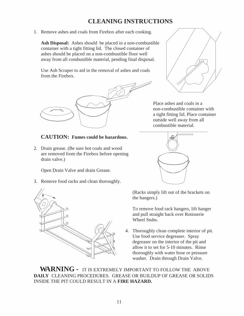
1. Remove ashes and coals from Firebox after each cooking.
Ash Disposal: Ashes should be placed in a non-combustible container with a tight fitting lid. The closed container of ashes should be placed on a non-combustible floor well away from all combustible material, pending final disposal.
Use Ash Scraper to aid in the removal of ashes and coals from the Firebox.
Place ashes and coals in anon-combustible container with
a tight fitting lid. Place containeroutside well away from allcombustible material.
CAUTION: Fumes could be hazardous.
2. Drain grease. (Be sure hot coals and wood are removed from the Firebox before opening drain valve.)
Open Drain Valve and drain Grease.
3. Remove food racks and clean thoroughly.
(Racks simply lift out of the brackets on the hangers.)
To remove food rack hangers, lift hanger and pull straight back over Rotisserie Wheel Stubs.
4. Thoroughly clean complete interior of pit. Use food service degreaser. Spray degreaser on the interior of the pit and allow it to set for 5-10 minutes. Rinse thoroughly with water hose or pressure washer. Drain through Drain Valve.
WARNING - IT IS EXTREMELY IMPORTANT TO FOLLOW THE ABOVEDAILY CLEANING PROCEDURES. GREASE OR BUILDUP OF GREASE OR SOLIDSINSIDE THE PIT COULD RESULT IN A FIRE HAZARD.
CLEANING INSTRUCTIONS
11
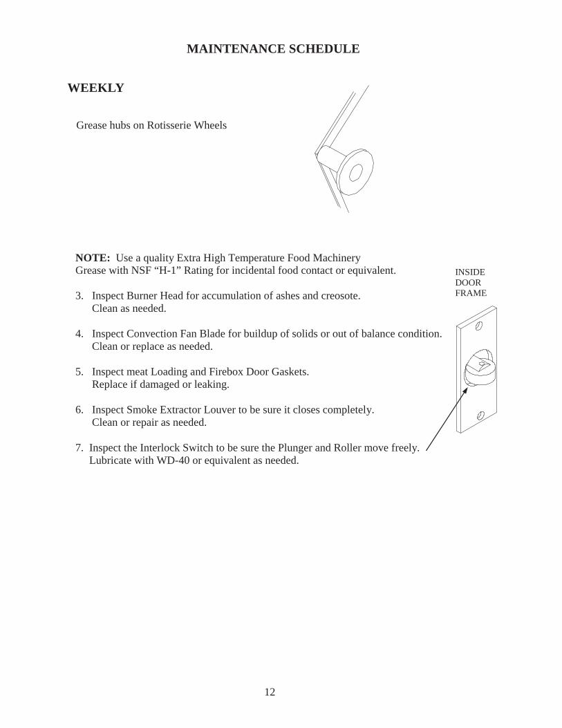
MAINTENANCE SCHEDULE
WEEKLY
Grease hubs on Rotisserie Wheels
NOTE: Use a quality Extra High Temperature Food MachineryGrease with NSF “H-1” Rating for incidental food contact or equivalent.
3. Inspect Burner Head for accumulation of ashes and creosote. Clean as needed.
4. Inspect Convection Fan Blade for buildup of solids or out of balance condition. Clean or replace as needed.
5. Inspect meat Loading and Firebox Door Gaskets. Replace if damaged or leaking.
6. Inspect Smoke Extractor Louver to be sure it closes completely. Clean or repair as needed.
7. Inspect the Interlock Switch to be sure the Plunger and Roller move freely. Lubricate with WD-40 or equivalent as needed.
12
INSIDEDOORFRAME
BI-MONTHLY INTERVAL
1. The Chimney Connector and Chimney should be inspected at least twice monthly to determine if creosote buildup has occurred.
2. The Flue Pipe should be carefully inspected. Remove any buildup of solids that has accumulated.
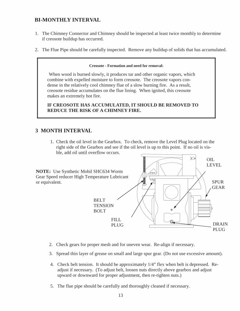
1. Check the oil level in the Gearbox. To check, remove the Level Plug located on the right side of the Gearbox and see if the oil level is up to this point. If no oil is vis- ble, add oil until overflow occurs.
2. Check gears for proper mesh and for uneven wear. Re-align if necessary.
3. Spread thin layer of grease on small and large spur gear. (Do not use excessive amount).
4. Check belt tension. It should be approximately 1/4” flex when belt is depressed. Re- adjust if necessary. (To adjust belt, loosen nuts directly above gearbox and adjust upward or downward for proper adjustment, then re-tighten nuts.)
5. The flue pipe should be carefully and thoroughly cleaned if necessary.
3 MONTH INTERVAL
NOTE: Use Synthetic Mobil SHC634 WormGear Speed reducer High Temperature Lubricantor equivalent.
13
OILLEVEL
DRAINPLUG
FILLPLUG
BELTTENSIONBOLT
SPURGEAR
Creosote - Formation and need for removal:
When wood is burned slowly, it produces tar and other organic vapors, which combine with expelled moisture to form creosote. The creosote vapors con- dense in the relatively cool chimney flue of a slow burning fire. As a result, creosote residue accumulates on the flue lining. When ignited, this creosote makes an extremely hot fire.
IF CREOSOTE HAS ACCUMULATED, IT SHOULD BE REMOVED TO REDUCE THE RISK OF A CHIMNEY FIRE.
ELECTRICAL INSTRUCTIONS
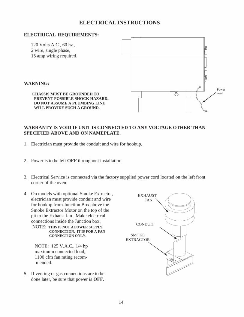
ELECTRICAL REQUIREMENTS:
120 Volts A.C., 60 hz., 2 wire, single phase, 15 amp wiring required.
WARNING:
CHASSIS MUST BE GROUNDED TO PREVENT POSSIBLE SHOCK HAZARD. DO NOT ASSUME A PLUMBING LINE WILL PROVIDE SUCH A GROUND.
WARRANTY IS VOID IF UNIT IS CONNECTED TO ANY VOLTAGE OTHER THANSPECIFIED ABOVE AND ON NAMEPLATE.
1. Electrician must provide the conduit and wire for hookup.
2. Power is to be left OFF throughout installation.
3. Electrical Service is connected via the factory supplied power cord located on the left front corner of the oven.
4. On models with optional Smoke Extractor, electrician must provide conduit and wire for hookup from Junction Box above the Smoke Extractor Motor on the top of the pit to the Exhaust fan. Make electrical connections inside the Junction box. NOTE: THIS IS NOT A POWER SUPPLY CONNECTION. IT IS FOR A FAN CONNECTION ONLY.
NOTE: 125 V.A.C., 1/4 hp maximum connected load, 1100 cfm fan rating recom- mended.
5. If venting or gas connections are to be done later, be sure that power is OFF.
14
EXHAUSTFAN
CONDUIT
SMOKEEXTRACTOR
Powercord
15
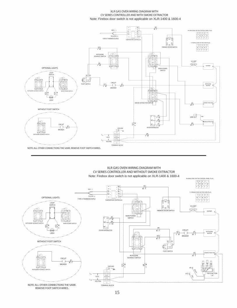
Note: Firebox door switch is not applicable on XLR-1400 & 1600-4
Note: Firebox door switch is not applicable on XLR-1400 & 1600-4
16
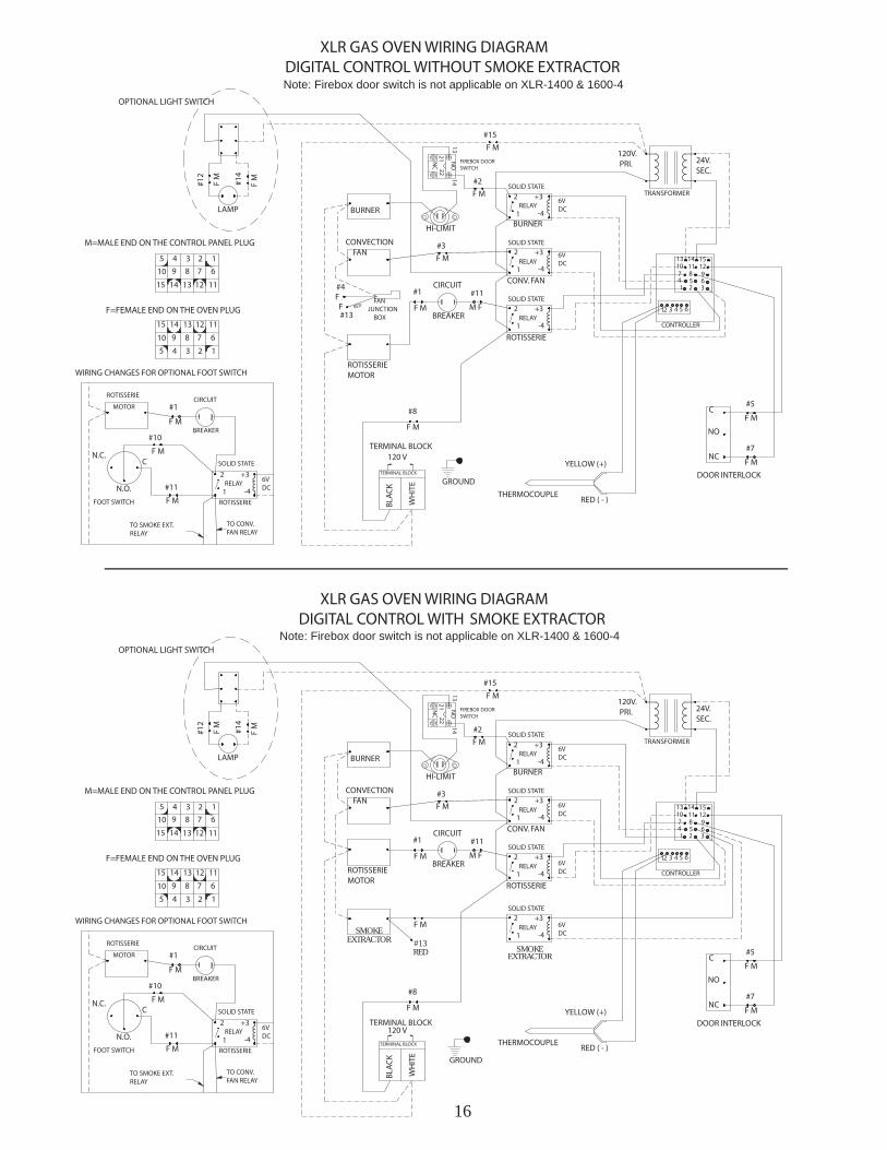
SMOKEEXTRACTOR
SMOKEEXTRACTOR #13
RED
Note: Firebox door switch is not applicable on XLR-1400 & 1600-4
Note: Firebox door switch is not applicable on XLR-1400 & 1600-4
17
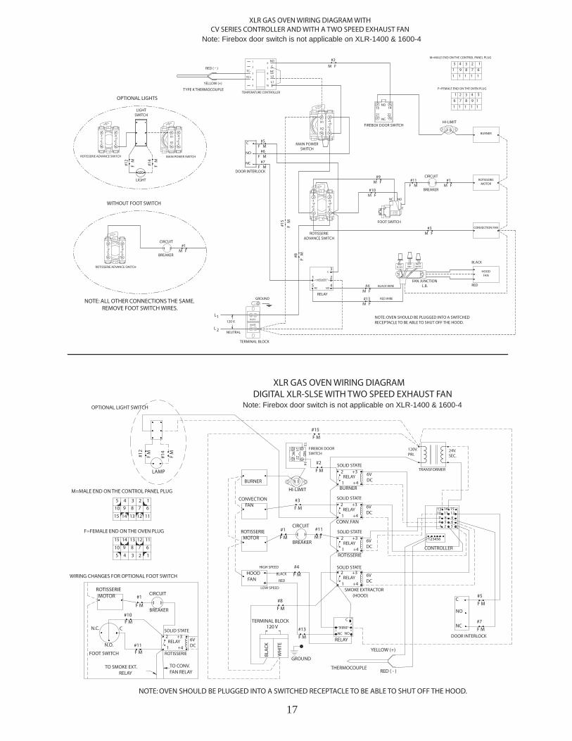
Note: Firebox door switch is not applicable on XLR-1400 & 1600-4
Note: Firebox door switch is not applicable on XLR-1400 & 1600-4
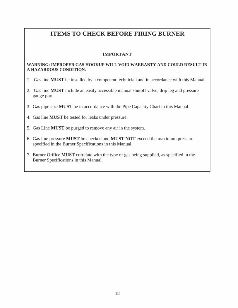
ITEMS TO CHECK BEFORE FIRING BURNER
IMPORTANT
WARNING: IMPROPER GAS HOOKUP WILL VOID WARRANTY AND COULD RESULT IN A HAZARDOUS CONDITION.
1. Gas line MUST be installed by a competent technician and in accordance with this Manual.
2. Gas line MUST include an easily accessible manual shutoff valve, drip leg and pressure gauge port.
3. Gas pipe size MUST be in accordance with the Pipe Capacity Chart in this Manual.
4. Gas line MUST be tested for leaks under pressure.
5. Gas Line MUST be purged to remove any air in the system.
6. Gas line pressure MUST be checked and MUST NOT exceed the maximum pressure specified in the Burner Specifications in this Manual.
7. Burner Orifice MUST correlate with the type of gas being supplied, as specified in the Burner Specifications in this Manual.
18
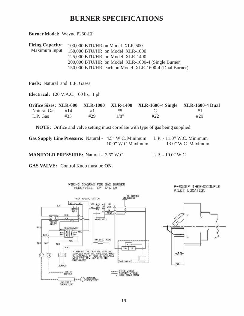
BURNER SPECIFICATIONS
Burner Model: Wayne P250-EP
Firing Capacity:Maximum Input
Fuels: Natural and L.P. Gases
Electrical: 120 V.A.C., 60 hz, 1 ph
Orifice Sizes: XLR-600 XLR-1000 XLR-1400 XLR-1600-4 Single XLR-1600-4 DualNatural Gas #14 #1 #5 G #1
L.P. Gas #35 #29 1/8” #22 #29
NOTE: Orifice and valve setting must correlate with type of gas being supplied.
Gas Supply Line Pressure: Natural - 4.5” W.C. Minimum L.P. - 11.0” W.C. Minimum 10.0” W.C Maximum 13.0” W.C. Maximum
MANIFOLD PRESSURE: Natural - 3.5” W.C. L.P. - 10.0” W.C.
GAS VALVE: Control Knob must be ON.
19
100,000 BTU/HR on Model XLR-600150,000 BTU/HR on Model XLR-1000125,000 BTU/HR on Model XLR-1400200,000 BTU/HR on Model XLR-1600-4 (Single Burner)150,000 BTU/HR each on Model XLR-1600-4 (Dual Burner)
1. It is recommended that the model XLR-Series ovens be vented as shown on page 21.
2. It is recommended that Local Code Officials and a Commercial Kitchen Ventilation Contractor be consulted prior to installation.
3. Provisions must be made for adequate air supply for the oven. If the oven is to be installed in a sealed room or building utilizing exhaust fans, the room must be supplied with a return air system. Return air must be equal or in excess of the exhausted air.
4. Unit must be level for proper grease drainage.
5. Minimum spacing to combustible materials: Back-2” (although 10” is recommended for servicing the unit) Left Side-18” (access for service) Note: If provision is made for service access, Left Side clearance can be reduced to 2”. Right Side-24” Access to load and unload firebox. Top-18” Front-48” (access for loading and unloading product) Chimney Connectors-18” Floor-May be combustible material.
NOTE: On ovens that have the reverse firebox or mirror image option, (Facing the meat loading doors the firebox door is on the right) The minimum clearance dimensions for the left side and right side will be reversed.
NOTE: For flush mount, use BBR Insulation Kit #2908.
VENTING INSTRUCTIONS
20
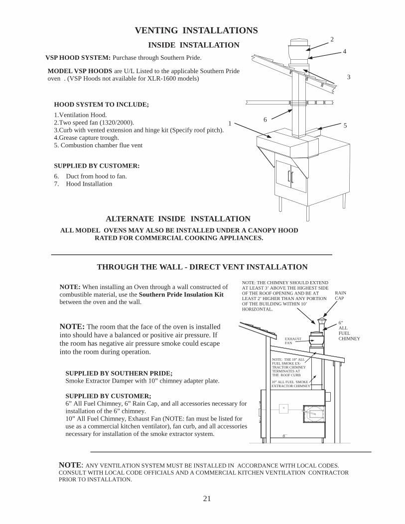
VENTING INSTALLATIONS
NOTE: ANY VENTILATION SYSTEM MUST BE INSTALLED IN ACCORDANCE WITH LOCAL CODES.CONSULT WITH LOCAL CODE OFFICIALS AND A COMMERCIAL KITCHEN VENTILATION CONTRACTORPRIOR TO INSTALLATION.
SUPPLIED BY CUSTOMER:
6. Duct from hood to fan.7. Hood Installation
HOOD SYSTEM TO INCLUDE;
1.Ventilation Hood.2.Two speed fan (1320/2000).3.Curb with vented extension and hinge kit (Specify roof pitch).4.Grease capture trough.5. Combustion chamber flue vent
6
4
2
1
3
NOTE: When installing an Oven through a wall constructed ofcombustible material, use the Southern Pride Insulation Kitbetween the oven and the wall.
INSIDE INSTALLATION
5
6”ALLFUELCHIMNEY
RAINCAP
MODEL VSP HOODS are U/L Listed to the applicable Southern Prideoven . (VSP Hoods not available for XLR-1600 models)
THROUGH THE WALL - DIRECT VENT INSTALLATION
ALL MODEL OVENS MAY ALSO BE INSTALLED UNDER A CANOPY HOODRATED FOR COMMERCIAL COOKING APPLIANCES.
NOTE: The room that the face of the oven is installedinto should have a balanced or positive air pressure. Ifthe room has negative air pressure smoke could escapeinto the room during operation.
NOTE: THE CHIMNEY SHOULD EXTENDAT LEAST 3’ ABOVE THE HIGHEST SIDEOF THE ROOF OPENING AND BE ATLEAST 2’ HIGHER THAN ANY PORTIONOF THE BUILDING WITHIN 10’HORIZONTAL.
VSP HOOD SYSTEM: Purchase through Southern Pride.
ALTERNATE INSIDE INSTALLATION
SUPPLIED BY SOUTHERN PRIDE;Smoke Extractor Damper with 10” chimney adapter plate.
SUPPLIED BY CUSTOMER;6” All Fuel Chimney, 6” Rain Cap, and all accessories necessary forinstallation of the 6” chimney.10” All Fuel Chimney, Exhaust Fan (NOTE: fan must be listed foruse as a commercial kitchen ventilator), fan curb, and all accessoriesnecessary for installation of the smoke extractor system.
21
10” ALL FUEL SMOKEEXTRACTOR CHIMNEY
EXHAUSTFAN
NOTE: THE 10” ALLFUEL SMOKE EX-TRACTOR CHIMNEYTERMINATES ATTHE ROOF CURB
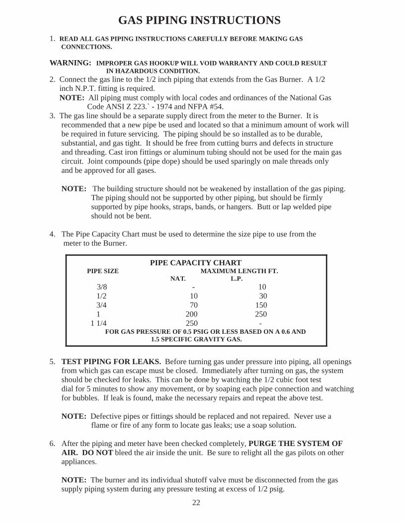
GAS PIPING INSTRUCTIONS1. READ ALL GAS PIPING INSTRUCTIONS CAREFULLY BEFORE MAKING GAS CONNECTIONS.
WARNING: IMPROPER GAS HOOKUP WILL VOID WARRANTY AND COULD RESULT IN HAZARDOUS CONDITION.2. Connect the gas line to the 1/2 inch piping that extends from the Gas Burner. A 1/2 inch N.P.T. fitting is required.
NOTE: All piping must comply with local codes and ordinances of the National Gas Code ANSI Z 223.` - 1974 and NFPA #54.3. The gas line should be a separate supply direct from the meter to the Burner. It is recommended that a new pipe be used and located so that a minimum amount of work will be required in future servicing. The piping should be so installed as to be durable, substantial, and gas tight. It should be free from cutting burrs and defects in structure and threading. Cast iron fittings or aluminum tubing should not be used for the main gas circuit. Joint compounds (pipe dope) should be used sparingly on male threads only and be approved for all gases.
NOTE: The building structure should not be weakened by installation of the gas piping. The piping should not be supported by other piping, but should be firmly supported by pipe hooks, straps, bands, or hangers. Butt or lap welded pipe should not be bent.
4. The Pipe Capacity Chart must be used to determine the size pipe to use from the meter to the Burner.
5. TEST PIPING FOR LEAKS. Before turning gas under pressure into piping, all openings from which gas can escape must be closed. Immediately after turning on gas, the system should be checked for leaks. This can be done by watching the 1/2 cubic foot test dial for 5 minutes to show any movement, or by soaping each pipe connection and watching for bubbles. If leak is found, make the necessary repairs and repeat the above test.
NOTE: Defective pipes or fittings should be replaced and not repaired. Never use a flame or fire of any form to locate gas leaks; use a soap solution.
6. After the piping and meter have been checked completely, PURGE THE SYSTEM OF AIR. DO NOT bleed the air inside the unit. Be sure to relight all the gas pilots on other appliances.
NOTE: The burner and its individual shutoff valve must be disconnected from the gas supply piping system during any pressure testing at excess of 1/2 psig.
22
PIPE CAPACITY CHART PIPE SIZE MAXIMUM LENGTH FT. NAT. L.P.
3/8 - 10 1/2 10 30 3/4 70 150 1 200 250 1 1/4 250 -
FOR GAS PRESSURE OF 0.5 PSIG OR LESS BASED ON A 0.6 AND1.5 SPECIFIC GRAVITY GAS.
XLR-600, XLR-1000, XLR-1400, & XLR-1600-4REPLACEMENT PARTS LIST
23
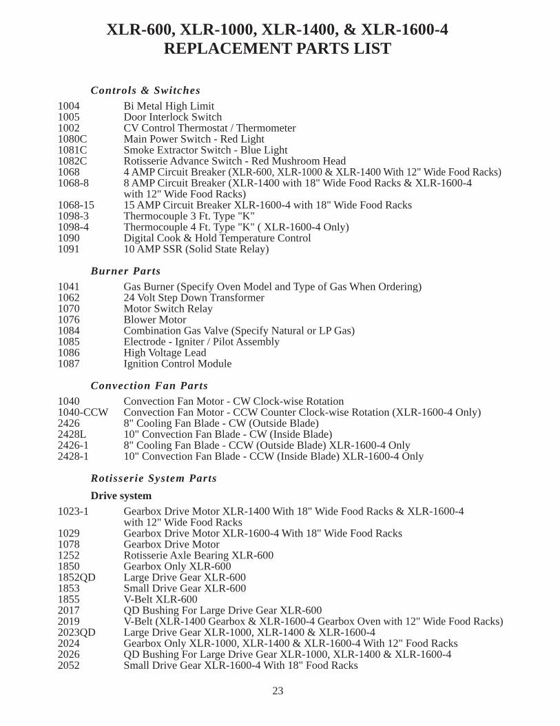
Controls & Switches1004 Bi Metal High Limit1005 Door Interlock Switch1002 CV Control Thermostat / Thermometer1080C Main Power Switch - Red Light1081C Smoke Extractor Switch - Blue Light1082C Rotisserie Advance Switch - Red Mushroom Head1068 4 AMP Circuit Breaker (XLR-600, XLR-1000 & XLR-1400 With 12" Wide Food Racks)1068-8 8 AMP Circuit Breaker (XLR-1400 with 18" Wide Food Racks & XLR-1600-4
with 12" Wide Food Racks)1068-15 15 AMP Circuit Breaker XLR-1600-4 with 18" Wide Food Racks1098-3 Thermocouple 3 Ft. Type "K"1098-4 Thermocouple 4 Ft. Type "K" ( XLR-1600-4 Only)1090 Digital Cook & Hold Temperature Control1091 10 AMP SSR (Solid State Relay)
Burner Parts1041 Gas Burner (Specify Oven Model and Type of Gas When Ordering)1062 24 Volt Step Down Transformer1070 Motor Switch Relay1076 Blower Motor1084 Combination Gas Valve (Specify Natural or LP Gas)1085 Electrode - Igniter / Pilot Assembly1086 High Voltage Lead1087 Ignition Control Module
Convection Fan Parts1040 Convection Fan Motor - CW Clock-wise Rotation1040-CCW Convection Fan Motor - CCW Counter Clock-wise Rotation (XLR-1600-4 Only)2426 8" Cooling Fan Blade - CW (Outside Blade)2428L 10" Convection Fan Blade - CW (Inside Blade)2426-1 8" Cooling Fan Blade - CCW (Outside Blade) XLR-1600-4 Only2428-1 10" Convection Fan Blade - CCW (Inside Blade) XLR-1600-4 Only
Rotisserie System Parts
Drive system1023-1 Gearbox Drive Motor XLR-1400 With 18" Wide Food Racks & XLR-1600-4
with 12" Wide Food Racks1029 Gearbox Drive Motor XLR-1600-4 With 18" Wide Food Racks1078 Gearbox Drive Motor1252 Rotisserie Axle Bearing XLR-6001850 Gearbox Only XLR-6001852QD Large Drive Gear XLR-6001853 Small Drive Gear XLR-6001855 V-Belt XLR-6002017 QD Bushing For Large Drive Gear XLR-6002019 V-Belt (XLR-1400 Gearbox & XLR-1600-4 Gearbox Oven with 12" Wide Food Racks)2023QD Large Drive Gear XLR-1000, XLR-1400 & XLR-1600-42024 Gearbox Only XLR-1000, XLR-1400 & XLR-1600-4 With 12" Food Racks2026 QD Bushing For Large Drive Gear XLR-1000, XLR-1400 & XLR-1600-42052 Small Drive Gear XLR-1600-4 With 18" Food Racks
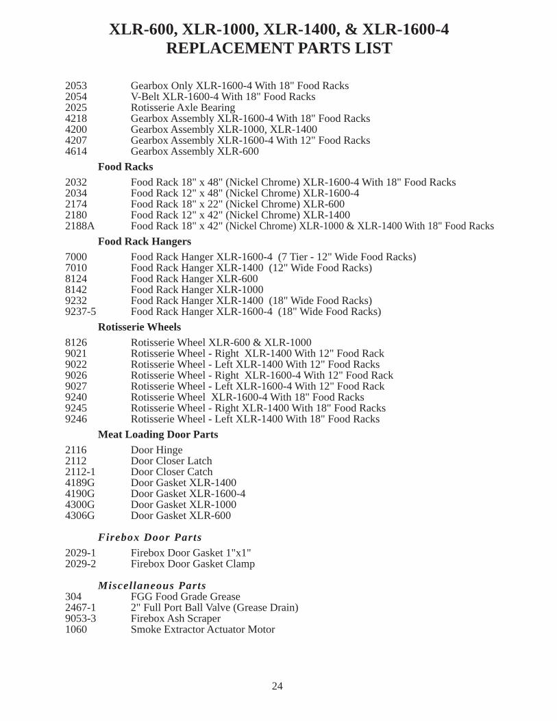
2053 Gearbox Only XLR-1600-4 With 18" Food Racks2054 V-Belt XLR-1600-4 With 18" Food Racks2025 Rotisserie Axle Bearing4218 Gearbox Assembly XLR-1600-4 With 18" Food Racks4200 Gearbox Assembly XLR-1000, XLR-14004207 Gearbox Assembly XLR-1600-4 With 12" Food Racks4614 Gearbox Assembly XLR-600
Food Racks2032 Food Rack 18" x 48" (Nickel Chrome) XLR-1600-4 With 18" Food Racks2034 Food Rack 12" x 48" (Nickel Chrome) XLR-1600-42174 Food Rack 18" x 22" (Nickel Chrome) XLR-6002180 Food Rack 12" x 42" (Nickel Chrome) XLR-14002188A Food Rack 18" x 42" (Nickel Chrome) XLR-1000 & XLR-1400 With 18" Food Racks
Food Rack Hangers7000 Food Rack Hanger XLR-1600-4 (7 Tier - 12" Wide Food Racks)7010 Food Rack Hanger XLR-1400 (12" Wide Food Racks)8124 Food Rack Hanger XLR-6008142 Food Rack Hanger XLR-10009232 Food Rack Hanger XLR-1400 (18" Wide Food Racks)9237-5 Food Rack Hanger XLR-1600-4 (18" Wide Food Racks)
Rotisserie Wheels8126 Rotisserie Wheel XLR-600 & XLR-10009021 Rotisserie Wheel - Right XLR-1400 With 12" Food Rack9022 Rotisserie Wheel - Left XLR-1400 With 12" Food Racks9026 Rotisserie Wheel - Right XLR-1600-4 With 12" Food Rack9027 Rotisserie Wheel - Left XLR-1600-4 With 12" Food Rack9240 Rotisserie Wheel XLR-1600-4 With 18" Food Racks9245 Rotisserie Wheel - Right XLR-1400 With 18" Food Racks9246 Rotisserie Wheel - Left XLR-1400 With 18" Food Racks
Meat Loading Door Parts2116 Door Hinge2112 Door Closer Latch2112-1 Door Closer Catch4189G Door Gasket XLR-14004190G Door Gasket XLR-1600-44300G Door Gasket XLR-10004306G Door Gasket XLR-600
Firebox Door Parts2029-1 Firebox Door Gasket 1"x1"2029-2 Firebox Door Gasket Clamp
Miscellaneous Parts304 FGG Food Grade Grease2467-1 2" Full Port Ball Valve (Grease Drain)9053-3 Firebox Ash Scraper1060 Smoke Extractor Actuator Motor
XLR-600, XLR-1000, XLR-1400, & XLR-1600-4REPLACEMENT PARTS LIST
24
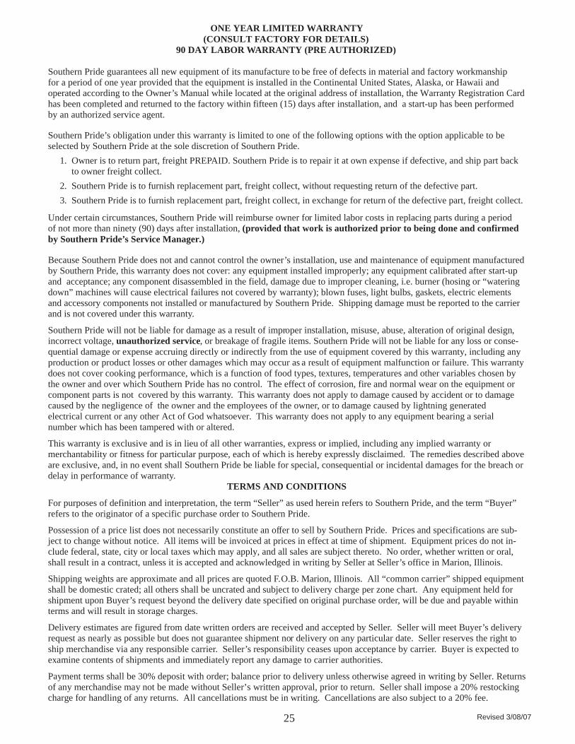
ONE YEAR LIMITED WARRANTY(CONSULT FACTORY FOR DETAILS)
90 DAY LABOR WARRANTY (PRE AUTHORIZED)
Southern Pride guarantees all new equipment of its manufacture to be free of defects in material and factory workmanshipfor a period of one year provided that the equipment is installed in the Continental United States, Alaska, or Hawaii andoperated according to the Owner’s Manual while located at the original address of installation, the Warranty Registration Cardhas been completed and returned to the factory within fifteen (15) days after installation, and a start-up has been performedby an authorized service agent.
Southern Pride’s obligation under this warranty is limited to one of the following options with the option applicable to beselected by Southern Pride at the sole discretion of Southern Pride.
1. Owner is to return part, freight PREPAID. Southern Pride is to repair it at own expense if defective, and ship part back to owner freight collect.
2. Southern Pride is to furnish replacement part, freight collect, without requesting return of the defective part.
3. Southern Pride is to furnish replacement part, freight collect, in exchange for return of the defective part, freight collect.
Under certain circumstances, Southern Pride will reimburse owner for limited labor costs in replacing parts during a periodof not more than ninety (90) days after installation, (provided that work is authorized prior to being done and confirmedby Southern Pride’s Service Manager.)
Because Southern Pride does not and cannot control the owner’s installation, use and maintenance of equipment manufacturedby Southern Pride, this warranty does not cover: any equipment installed improperly; any equipment calibrated after start-upand acceptance; any component disassembled in the field, damage due to improper cleaning, i.e. burner (hosing or “wateringdown” machines will cause electrical failures not covered by warranty); blown fuses, light bulbs, gaskets, electric elementsand accessory components not installed or manufactured by Southern Pride. Shipping damage must be reported to the carrierand is not covered under this warranty.
Southern Pride will not be liable for damage as a result of improper installation, misuse, abuse, alteration of original design,incorrect voltage, unauthorized service, or breakage of fragile items. Southern Pride will not be liable for any loss or conse-quential damage or expense accruing directly or indirectly from the use of equipment covered by this warranty, including anyproduction or product losses or other damages which may occur as a result of equipment malfunction or failure. This warrantydoes not cover cooking performance, which is a function of food types, textures, temperatures and other variables chosen bythe owner and over which Southern Pride has no control. The effect of corrosion, fire and normal wear on the equipment orcomponent parts is not covered by this warranty. This warranty does not apply to damage caused by accident or to damagecaused by the negligence of the owner and the employees of the owner, or to damage caused by lightning generatedelectrical current or any other Act of God whatsoever. This warranty does not apply to any equipment bearing a serialnumber which has been tampered with or altered.
This warranty is exclusive and is in lieu of all other warranties, express or implied, including any implied warranty ormerchantability or fitness for particular purpose, each of which is hereby expressly disclaimed. The remedies described aboveare exclusive, and, in no event shall Southern Pride be liable for special, consequential or incidental damages for the breach ordelay in performance of warranty.
TERMS AND CONDITIONS
For purposes of definition and interpretation, the term “Seller” as used herein refers to Southern Pride, and the term “Buyer”refers to the originator of a specific purchase order to Southern Pride.
Possession of a price list does not necessarily constitute an offer to sell by Southern Pride. Prices and specifications are sub-ject to change without notice. All items will be invoiced at prices in effect at time of shipment. Equipment prices do not in-clude federal, state, city or local taxes which may apply, and all sales are subject thereto. No order, whether written or oral,shall result in a contract, unless it is accepted and acknowledged in writing by Seller at Seller’s office in Marion, Illinois.
Shipping weights are approximate and all prices are quoted F.O.B. Marion, Illinois. All “common carrier” shipped equipmentshall be domestic crated; all others shall be uncrated and subject to delivery charge per zone chart. Any equipment held forshipment upon Buyer’s request beyond the delivery date specified on original purchase order, will be due and payable withinterms and will result in storage charges.
Delivery estimates are figured from date written orders are received and accepted by Seller. Seller will meet Buyer’s deliveryrequest as nearly as possible but does not guarantee shipment nor delivery on any particular date. Seller reserves the right toship merchandise via any responsible carrier. Seller’s responsibility ceases upon acceptance by carrier. Buyer is expected toexamine contents of shipments and immediately report any damage to carrier authorities.
Payment terms shall be 30% deposit with order; balance prior to delivery unless otherwise agreed in writing by Seller. Returnsof any merchandise may not be made without Seller’s written approval, prior to return. Seller shall impose a 20% restockingcharge for handling of any returns. All cancellations must be in writing. Cancellations are also subject to a 20% fee.
25 Revised 3/08/07