
Variable Refrigerant Flow (VRF) A Better Option Through ... · Without using large distribution...
39
Variable Refrigerant Flow (VRF) – A Better Option Through Technology Let’s Find Out Why
Transcript of Variable Refrigerant Flow (VRF) A Better Option Through ... · Without using large distribution...
Variable Refrigerant Flow (VRF) – A Better Option
Through Technology
Let’s Find Out Why

Keith Pyatt
Sales Engineer LG Electronics, USA
CAC Division-Central Region ND, SD and MN
Office (636) 828-4337
Mobile (636) 577-6450
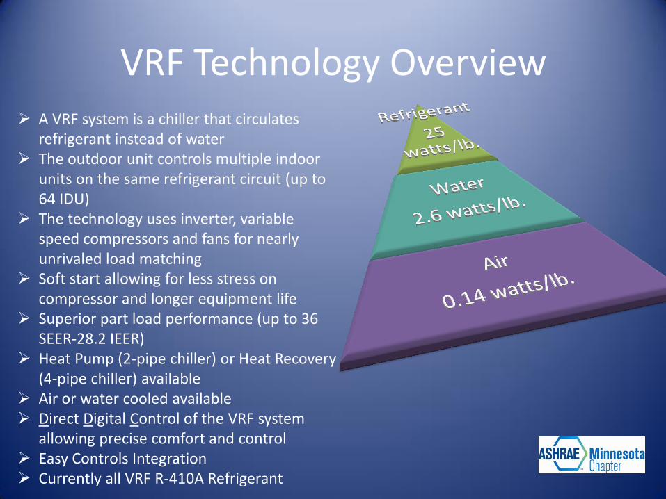
VRF Technology Overview A VRF system is a chiller that circulates
refrigerant instead of water The outdoor unit controls multiple indoor
units on the same refrigerant circuit (up to 64 IDU)
The technology uses inverter, variable speed compressors and fans for nearly unrivaled load matching
Soft start allowing for less stress on compressor and longer equipment life
Superior part load performance (up to 36 SEER-28.2 IEER)
Heat Pump (2-pipe chiller) or Heat Recovery (4-pipe chiller) available
Air or water cooled available Direct Digital Control of the VRF system
allowing precise comfort and control Easy Controls Integration Currently all VRF R-410A Refrigerant
The VRF Benefits
The modular design of VRF system results in superior energy savings giving occupants the choice to air condition or heat only the zones in use. A VRF system provides exceptional dehumidification and temperature control by rapidly adapting to changing loads.
Efficient Design:
Without using large distribution ducts, the VRF system removes losses that are unavoidable in other systems. In addition, the use of optimized scroll or rotary compressors, specially designed heat exchangers, and inverter technology, the VRF system minimizes energy consumption to levels previously unattainable by non-VRF systems. The modular design offers comfort on demand allowing the choice to use the system only in the zones where it is needed further promoting reduced energy consumption.
The VRF Benefits
Zoned Comfort Control & Dehumidification:
With the use of inverters and dual compressor outdoor units, the VRF system offers superior load matching, preventing constant cycling or large temperature swings. Tight temperature control through precise load matching ensures maximum comfort, efficient operation, and superior dehumidification. The modular design of VRF results in superior energy savings giving occupants the choice to air condition or heat only the zones in use.
Sustainability:
The architectural and engineering community is adopting a balanced design approach that considers energy and water consumption, repetitive maintenance costs, the impact of development on the environment, and the building’s initial cost as equally important factors in developing high performance, sustainable buildings that will increase building value. VRF systems help achieve points for sustainability programs.
The VRF Benefits
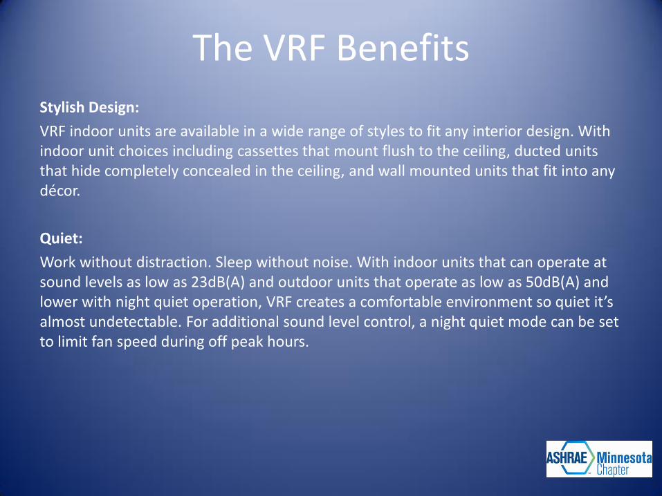
Stylish Design:
VRF indoor units are available in a wide range of styles to fit any interior design. With indoor unit choices including cassettes that mount flush to the ceiling, ducted units that hide completely concealed in the ceiling, and wall mounted units that fit into any décor.
Quiet:
Work without distraction. Sleep without noise. With indoor units that can operate at sound levels as low as 23dB(A) and outdoor units that operate as low as 50dB(A) and lower with night quiet operation, VRF creates a comfortable environment so quiet it’s almost undetectable. For additional sound level control, a night quiet mode can be set to limit fan speed during off peak hours.
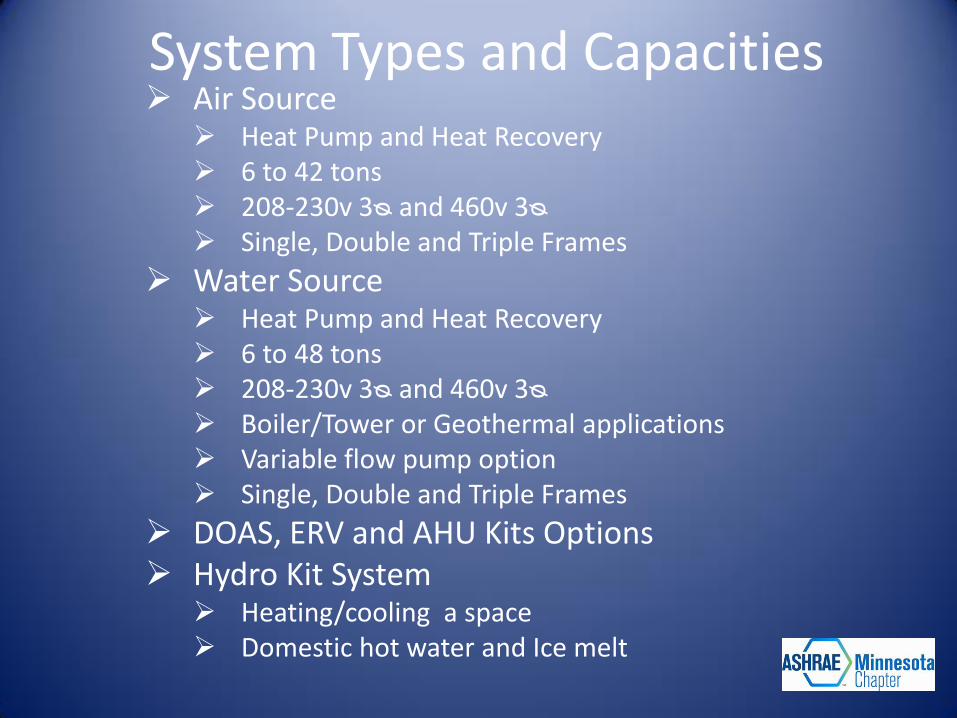
System Types and Capacities Air Source
Heat Pump and Heat Recovery 6 to 42 tons 208-230v 3ᴓ and 460v 3ᴓ Single, Double and Triple Frames
Water Source Heat Pump and Heat Recovery 6 to 48 tons 208-230v 3ᴓ and 460v 3ᴓ Boiler/Tower or Geothermal applications Variable flow pump option Single, Double and Triple Frames
DOAS, ERV and AHU Kits Options Hydro Kit System
Heating/cooling a space Domestic hot water and Ice melt
VRF Advanced Technological Features
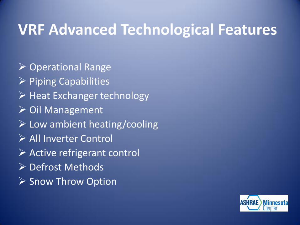
VRF Advanced Technological Features
Operational Range
Piping Capabilities
Heat Exchanger technology
Oil Management
Low ambient heating/cooling
All Inverter Control
Active refrigerant control
Defrost Methods
Snow Throw Option
Typical Operating Range
20
10
0
120
110
100
90
80
30
50
60
70
40
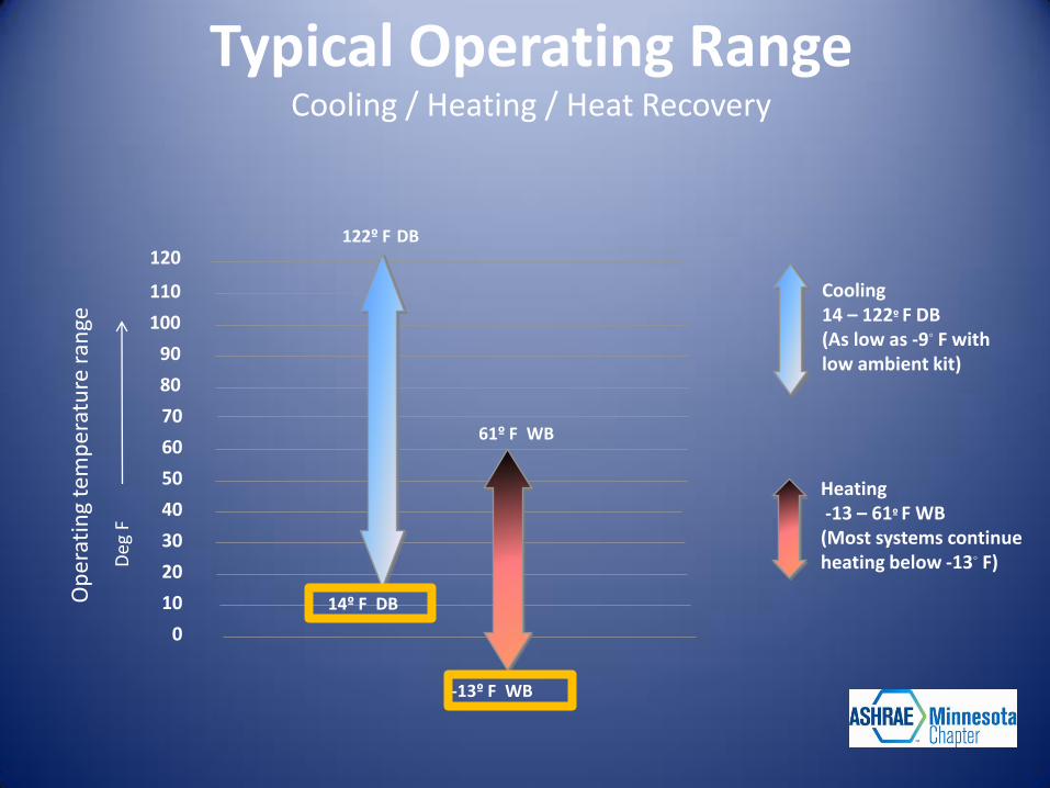
14º F DB
122º F DB
Cooling 14 – 122º F DB (As low as -9◦ F with low ambient kit)
-13º F WB
61º F WB
Heating -13 – 61º F WB (Most systems continue heating below -13◦ F) D
eg F
Op
erat
ing
tem
pe
ratu
re r
ange
Typical Operating Range
Cooling / Heating / Heat Recovery
VRF Piping Capabilities
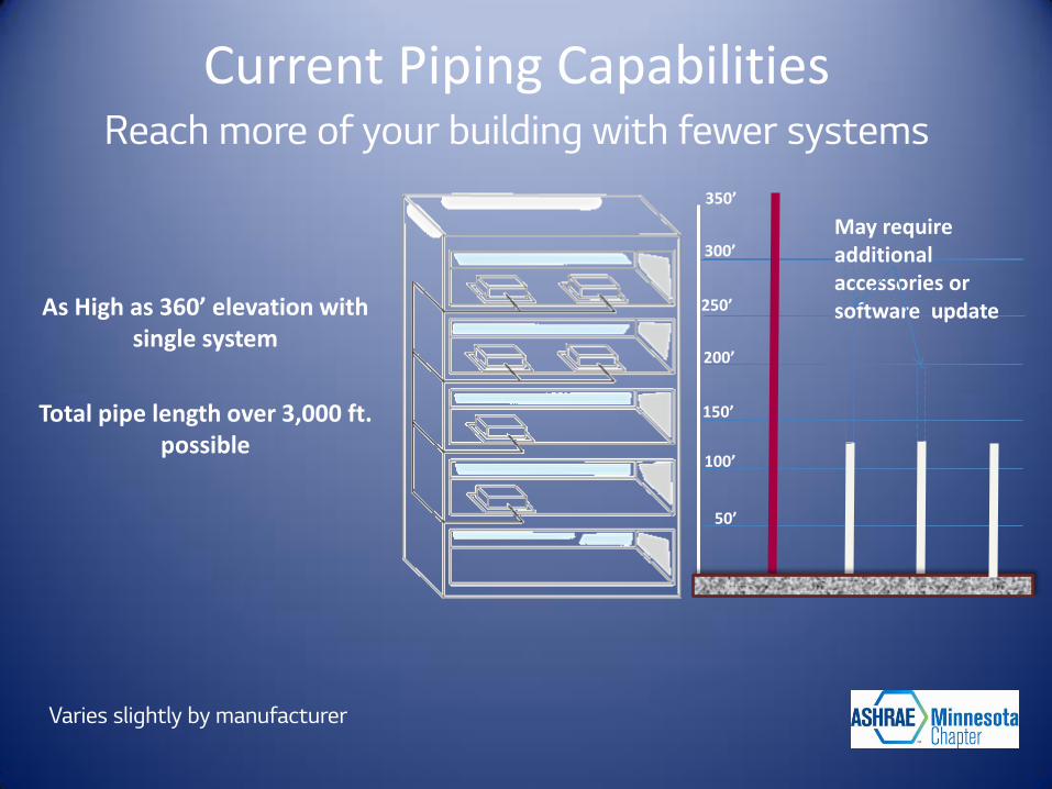
Current Piping Capabilities Reach more of your building with fewer systems
350’
300’
250’
200’
150’
100’
50’
May require additional accessories or software update
Varies slightly by manufacturer
As High as 360’ elevation with single system
Total pipe length over 3,000 ft. possible
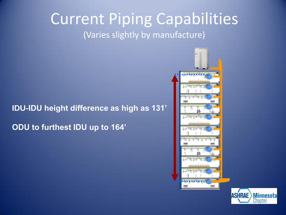
IDU-IDU height difference as high as 131’
ODU to furthest IDU up to 164’
Current Piping Capabilities (Varies slightly by manufacture)
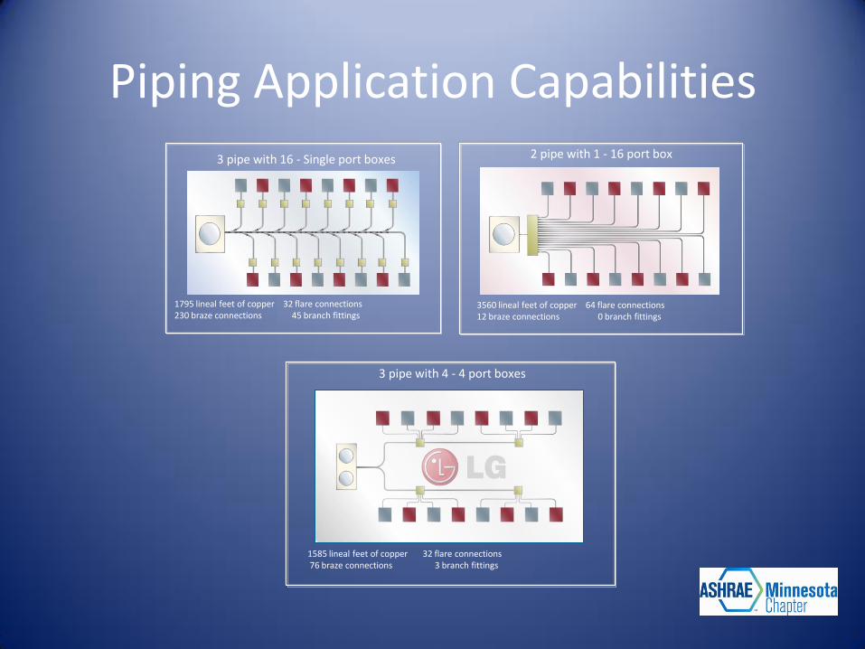
Piping Application Capabilities 3 pipe with 16 - Single port boxes
1795 lineal feet of copper 32 flare connections 230 braze connections 45 branch fittings
2 pipe with 1 - 16 port box
3560 lineal feet of copper 64 flare connections 12 braze connections 0 branch fittings
3 pipe with 4 - 4 port boxes
1585 lineal feet of copper 32 flare connections 76 braze connections 3 branch fittings
VRF Heat Exchanger Technology
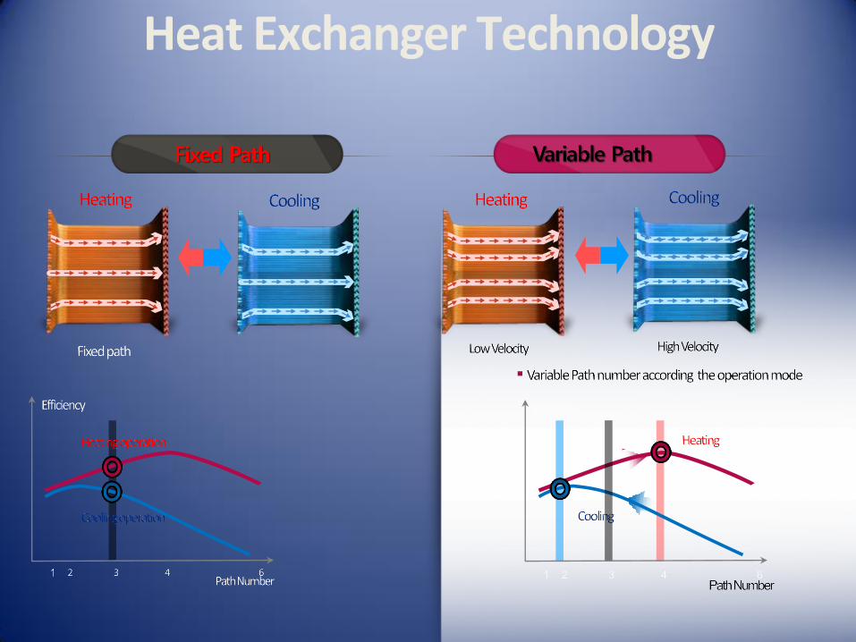
Heat Exchanger Technology
Oil Management Technology
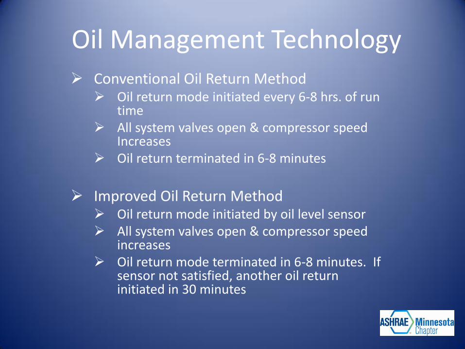
Oil Management Technology Conventional Oil Return Method
Oil return mode initiated every 6-8 hrs. of run time
All system valves open & compressor speed Increases
Oil return terminated in 6-8 minutes
Improved Oil Return Method
Oil return mode initiated by oil level sensor All system valves open & compressor speed
increases Oil return mode terminated in 6-8 minutes. If
sensor not satisfied, another oil return initiated in 30 minutes
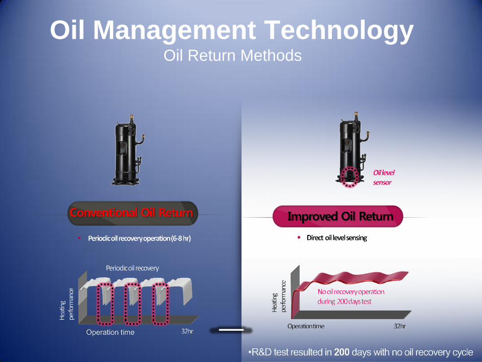
Oil Management Technology Oil Return Methods
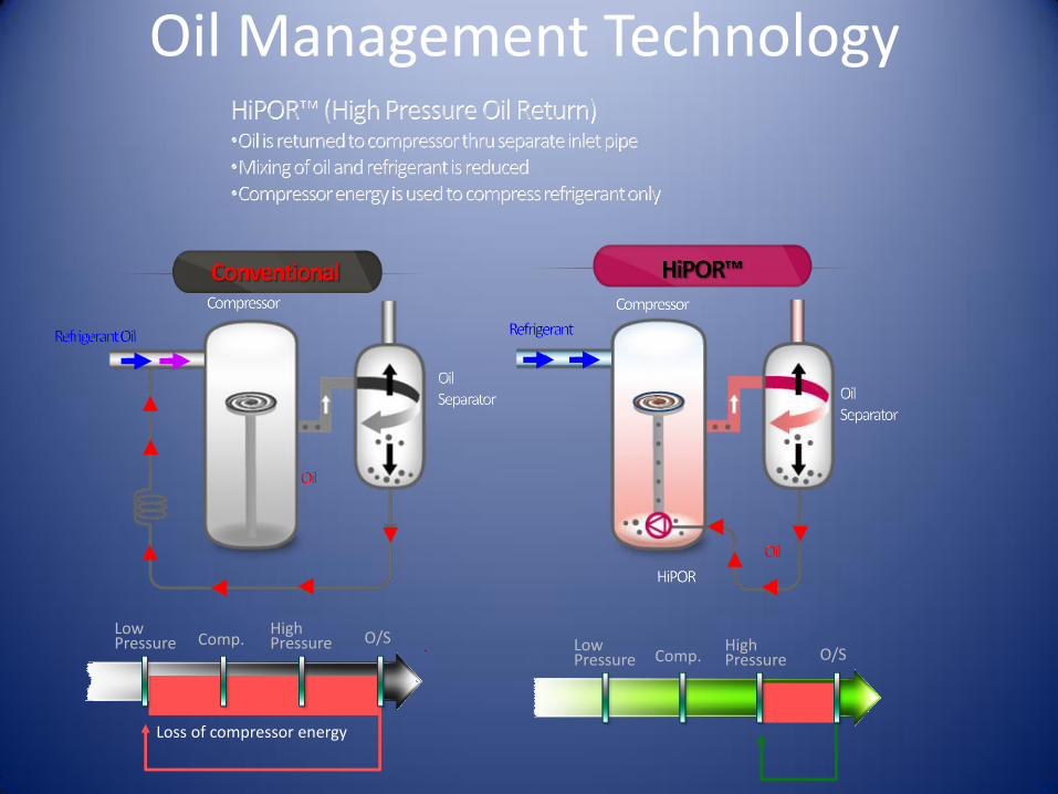
Low Pressure Comp.
High Pressure O/S
Loss of compressor energy
Low Pressure Comp.
High Pressure O/S
Oil Management Technology
Low Ambient Heating Technology
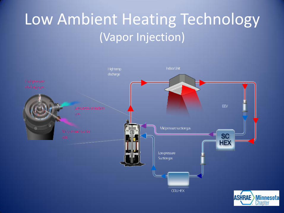
Low Ambient Heating Technology (Vapor Injection)
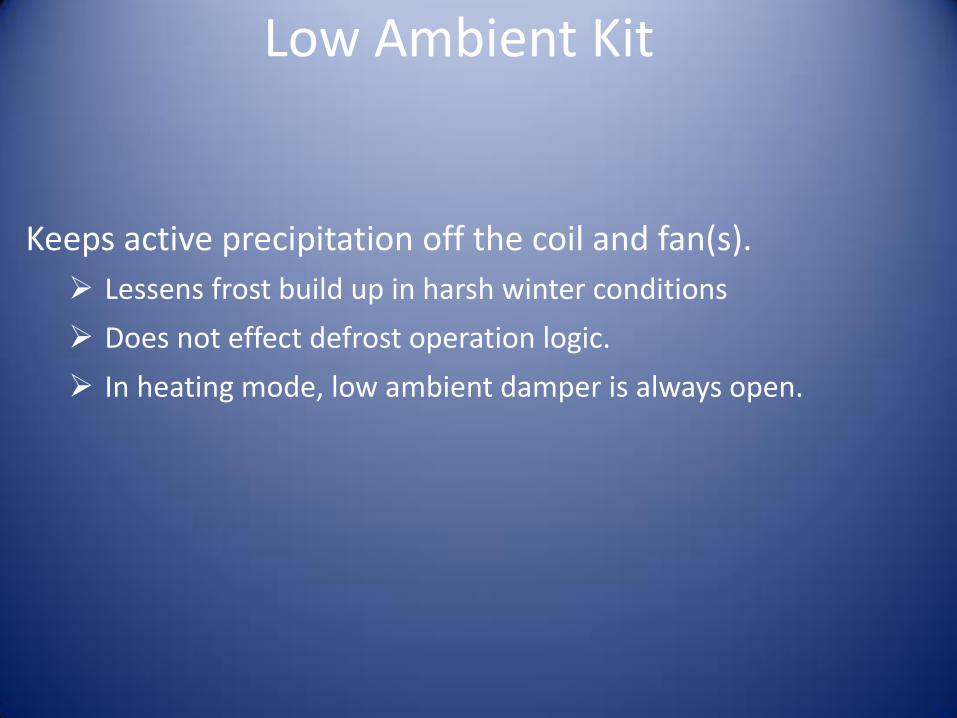
Low Ambient Kit
Keeps active precipitation off the coil and fan(s).
Lessens frost build up in harsh winter conditions
Does not effect defrost operation logic.
In heating mode, low ambient damper is always open.

All inverter Control Technology
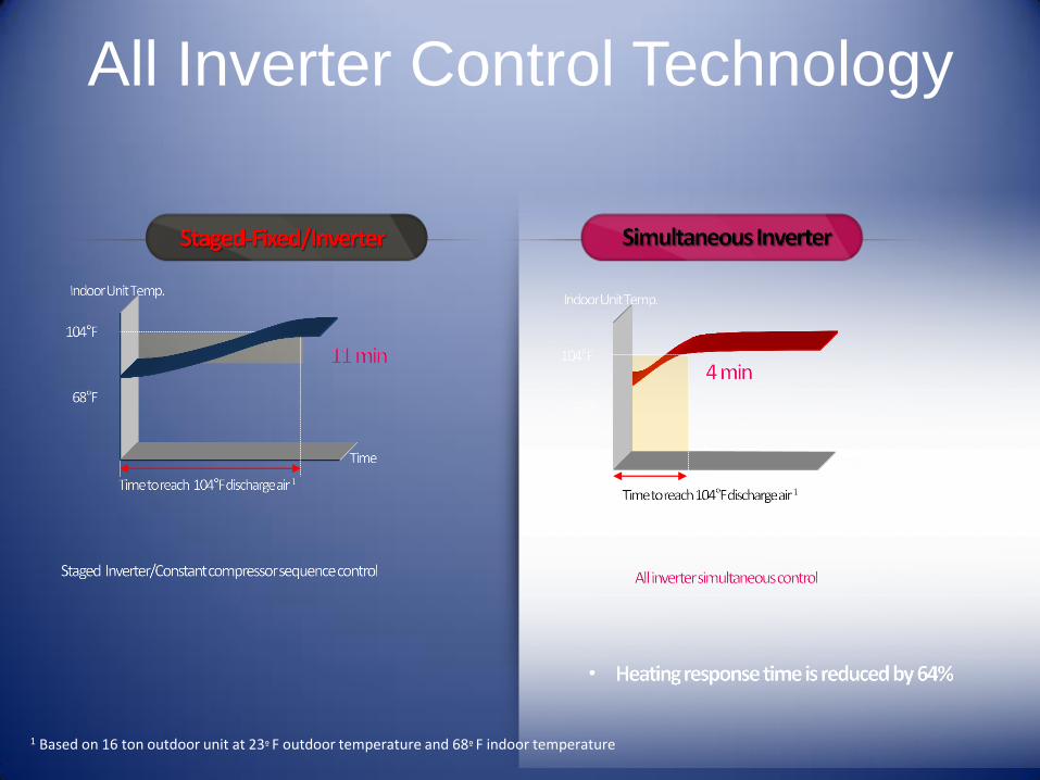
1 Based on 16 ton outdoor unit at 23º F outdoor temperature and 68º F indoor temperature
All Inverter Control Technology

Active Refrigerant Control Technology
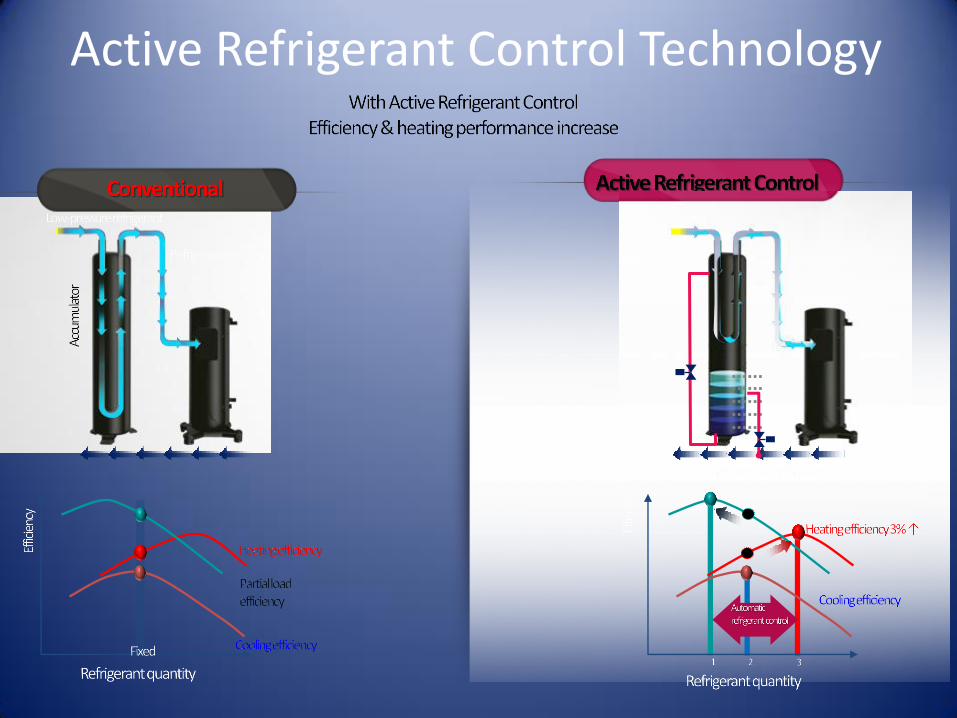
Active Refrigerant Control Technology
Defrost Methods
Mode Selection
Method Selection
Snow Throw Option
Defrost Mode Selection
Normal Defrost
Fast Defrost
“Normal” Defrost
31
Application Ideal for locations that experience mild winter temperatures with light to moderate humidity levels.
Operation Strategy Maximize heating run-time
• Allows frost to build longer before defrost
• Fewer defrost cycles
• Traditional VRF frost removal method
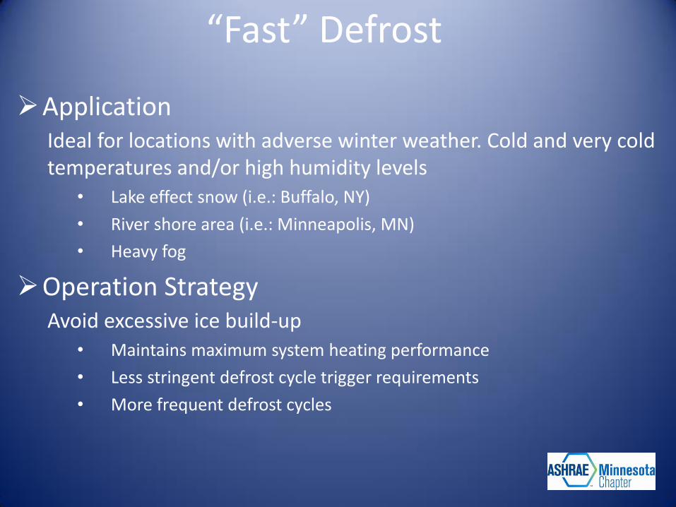
“Fast” Defrost
Application Ideal for locations with adverse winter weather. Cold and very cold temperatures and/or high humidity levels
• Lake effect snow (i.e.: Buffalo, NY)
• River shore area (i.e.: Minneapolis, MN)
• Heavy fog
Operation Strategy Avoid excessive ice build-up
• Maintains maximum system heating performance
• Less stringent defrost cycle trigger requirements
• More frequent defrost cycles
Split Coil/Frame Method
Application Ideal for locations with mild winter temperatures and light to moderate humidity levels.
Operation Strategy
Some VRF system continue to heat in defrost
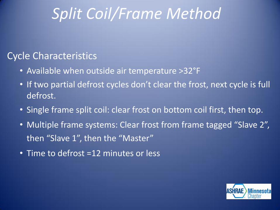
Split Coil/Frame Method
Cycle Characteristics
• Available when outside air temperature >32°F
• If two partial defrost cycles don’t clear the frost, next cycle is full defrost.
• Single frame split coil: clear frost on bottom coil first, then top.
• Multiple frame systems: Clear frost from frame tagged “Slave 2”,
then “Slave 1”, then the “Master”
• Time to defrost =12 minutes or less
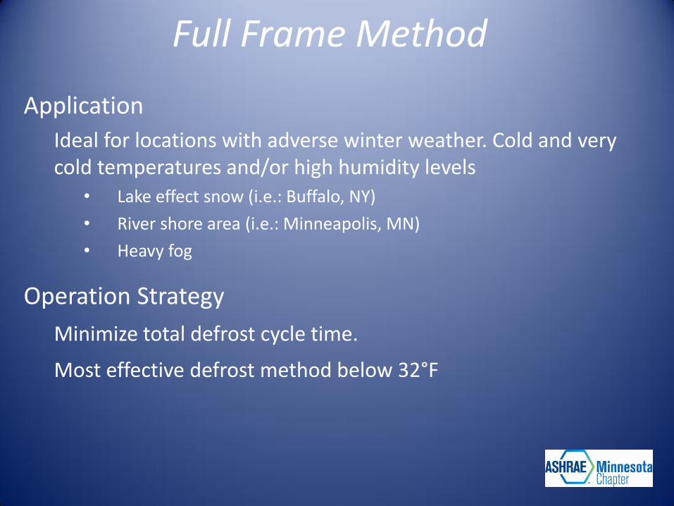
Full Frame Method
Application
Ideal for locations with adverse winter weather. Cold and very cold temperatures and/or high humidity levels
• Lake effect snow (i.e.: Buffalo, NY)
• River shore area (i.e.: Minneapolis, MN)
• Heavy fog
Operation Strategy
Minimize total defrost cycle time.
Most effective defrost method below 32°F
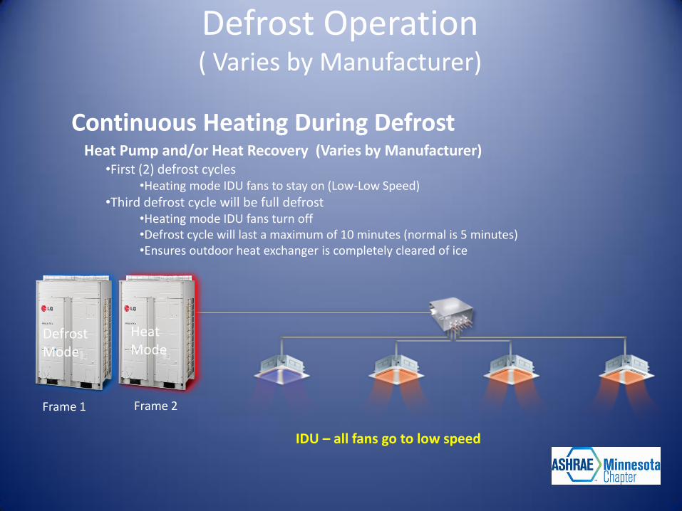
Continuous Heating During Defrost Heat Pump and/or Heat Recovery (Varies by Manufacturer)
•First (2) defrost cycles •Heating mode IDU fans to stay on (Low-Low Speed)
•Third defrost cycle will be full defrost •Heating mode IDU fans turn off •Defrost cycle will last a maximum of 10 minutes (normal is 5 minutes) •Ensures outdoor heat exchanger is completely cleared of ice
IDU – all fans go to low speed
Frame 1
Defrost Mode
Frame 2
Heat Mode
Defrost Operation ( Varies by Manufacturer)
Snow Throw Mode
Application Use in locations with moderate to heavy snowfall
Operation Strategy
Spins fan blades every ½ hour to clear snow buildup
• Minimize system malfunction errors resulting from ice interfering
with fan rotation.
Snow Throw Mode
Cycle Sequence 1. ODU fan(s) and compressor(s) are off for 30 minutes.
2. Temperature drops below 37°F
3. ODU fan(s) start and run on medium speed for 2 minutes
4. ODU fans cycle off
5. Repeat every 30 minutes until temperature >37°F

Thank You


![Welcome [ashraeqatar.org]ashraeqatar.org/.../5/4/34547927/4_evi_techonology_applications_in_… · pumps, boilers, chillers, ducts, piping, heat exchangers • VRF offers efficiency](https://static.fdocuments.net/doc/165x107/5e8d6e66a0747238aa515058/welcome-pumps-boilers-chillers-ducts-piping-heat-exchangers-a-vrf-offers.jpg)