The Redington Wind Farm - Maine.gov · The Redington Wind Farm Section 11: Soils ... Engineering...
59
The Redington Wind Farm Section 11: Soils Prepared by: Albert Frick Albert Frick Associates, Inc. 95A County Road Gorham, Maine 04038 (207) 839-5563 (207) 839-5564 (fax) [email protected]
Transcript of The Redington Wind Farm - Maine.gov · The Redington Wind Farm Section 11: Soils ... Engineering...
The Redington Wind Farm
Section 11: Soils
Prepared by: Albert Frick
Albert Frick Associates, Inc.
95A County Road
Gorham, Maine 04038
(207) 839-5563
(207) 839-5564 (fax)
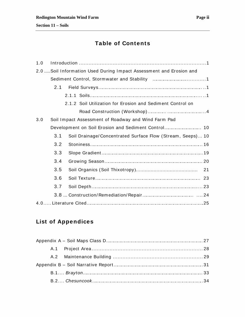
Redington Mountain Wind Farm Page ii
Section 11 – Soils
Table of Contents
1.0 Introduction ...............................................................................1
2.0 .....Soil Information Used During Impact Assessment and Erosion and
Sediment Control, Stormwater and Stability ……………………….............1
2.1 Field Surveys………………………………………………………………………….. ..1
2.1.1 Soils……………………………………………………………………………..... ..1
2.1.2 Soil Utilization for Erosion and Sediment Control on
Road Construction (Workshop)…………… ………………………....4
3.0 Soil Impact Assessment of Roadway and Wind Farm Pad
Development on Soil Erosion and Sediment Control………………………... 10
3.1 Soil Drainage/Concentrated Surface Flow (Stream, Seeps)… 10
3.2 Stoniness………………………………………………………………………………...16
3.3 Slope Gradient………………………………………………………………………… 19
3.4 Growing Season……………………………………………………………………… 20
3.5 Soil Organics (Soil Thixotropy)…………………………………… 21
3.6 Soil Texture…………………………………………………………………………… 23
3.7 Soil Depth……………………………………………………………………………....23
3.8 ... Construction/Remediation/Repair…………………………………… ....24
4.0.....Literature Cited…………………………………………………………………………………….25
List of Appendices
Appendix A – Soil Maps Class D……………………………………………………………………..27
A.1 Project Area .....................................................................28
A.2 Maintenance Building ........................................................29
Appendix B – Soil Narrative Report………………………………………………………………..31
B.1.... Brayton……………………………………………………………………………………… 33
B.2.... Chesuncook………………………………………………………………………………..34
Redington Mountain Wind Farm Page iii
Section 11 – Soils
B.3....Colonel………………………………………………………………………………………. 35
B.4.... Colton………………………………………………………………………………………… 36
B.5.....Dixfield……………………………………………………………………………………….37
B.6..... Hermon………………………………………………………………………………………38
B.7.....Lyman………………………………………………………………………………………..39
B.8.....Mahoosuc…………………………………………………………………………………..40
B.9..... Marlow……………………………………………………………………………………….41
B.10... Monadnock…………………………………………………………………………………42
B.11 .. Ricker…………………………………………………………………………………………43
B.12...Saddleback…………………………………………………………………………………44
B.13... Sheepscot………………………………………………………………………………….45
B.14...Sisk…………………………………………………………………………………………….46
B.15...Surplus……………………………………………………………………………………….47
B.16 Telos…………………………………………………………………………………………… 48
B.17...Tunbridge…………………………………………………………………………………..49
Appendix C – Letters of Correspondence…………………………………………………….. 50
Appendix D – Additional Photographs…………………………………………………………… 53
List of Tables
Table 1 Roadway Length Schedule…………………………………………………………...9
List of Figures
Figure 1 Existing Higher Elevation Roads Examined During……………………. .7
November 12, 2003 Field Workshop
Redington Mountain Wind Farm Page 1
Section 11 – Soils
1.0 Introduction
Redington Mountain Wind Farm LLC is proposing to develop an electric
generating facility from wind turbines. The project will include roadway
access up the mountainside and wind turbine sites along the ridge lines of
Mount Redington and Black Nubble. The purpose of the soil information is to
assist in developing erosion and sediment control methods applicable to
anticipated situations of combinations of soil conditions, drainage and slopes.
(See Appendix C pre-application letter regarding soil information
requirements) The soil information was used in coordination to develop
erosion and sediment control, and stormwater management techniques to
address LURC standards, specifically (10.25G). Engineering specifications of
Deluca-Hoffman are designed to meet or exceed these standards.
2.0 Soil Information Used During Impact Assessment
and Erosion and Sediment Control, Stormwater
and Stability
The information utilized to assess the impacts of the proposed project on the
soil resources and to develop erosion and sediment control methods, includes
field observation of soils on portions of road alignment, and available NRC
Service soil survey worksheets.
2.1 Field Surveys
2.1.1 Soils
Albert Frick Associates excavated hand-dug shovel test pits on August 22,
1994, August 23, 1994, September 22, 1994, September 11, 2001, and June
Redington Mountain Wind Farm Page 2
Section 11 – Soils
13, 2005, along proposed road alignments. The United States National
Resource Conservation Services field soil survey sheets for the immediate
area were assembled by Albert Frick Associates and registered onto the
project CAD site plan. (See Appendix A-1 for Soils Map, Appendix B for Soil
Narrative Report)
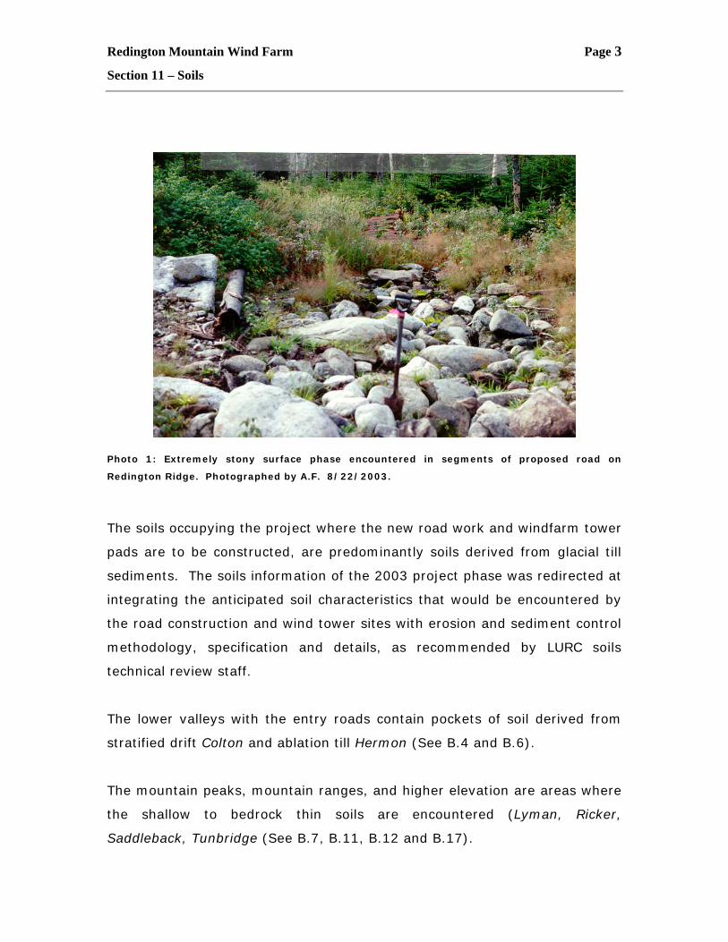
The soils information from earlier proposal effort (1994) of the Redington
Ridge alignment was done with hand-dug shovel test pits along the proposed
alignment. Hand shovels and hand augers were used in remote areas due to
the inaccessibility of mechanical excavators at that time. Hand tools have
limited ability to gather soils information due to the very stony surface
horizons. (See Photo 1) It was determined and agreed upon by working
with LURC, DEP and Soil and Water Conservation personnel during field
reviews and workshops during the 1994 project phase that integration of the
anticipated soil conditions, grades, and soil drainage would be more
meaningful for the permitting process. (See Appendix C, Albert Frick letter of
October 13, 2003 to David Rocque).
Redington Mountain Wind Farm Page 3
Section 11 – Soils
Photo 1: Extremely stony surface phase encountered in segments of proposed road on
Redington Ridge. Photographed by A.F. 8/22/2003.
The soils occupying the project where the new road work and windfarm tower
pads are to be constructed, are predominantly soils derived from glacial till
sediments. The soils information of the 2003 project phase was redirected at
integrating the anticipated soil characteristics that would be encountered by
the road construction and wind tower sites with erosion and sediment control
methodology, specification and details, as recommended by LURC soils
technical review staff.
The lower valleys with the entry roads contain pockets of soil derived from
stratified drift Colton and ablation till Hermon (See B.4 and B.6).
The mountain peaks, mountain ranges, and higher elevation are areas where
the shallow to bedrock thin soils are encountered (Lyman, Ricker,
Saddleback, Tunbridge (See B.7, B.11, B.12 and B.17).
Redington Mountain Wind Farm Page 4
Section 11 – Soils
In the higher positions in the uplands along the mountain side slopes, the
well drained glacial tills of Marlow, Monadnock. Sisk are encountered. (See
B.9, B.10, and B.14).
The middle position in the mountain side slope exhibits the moderately well
drained glacial till soils of Chesuncook, Dixfield and Surplus. (See B.2, B.5,
and B.15).
In the lower mountain side slopes in the uplands, and in borders of drainage
swales are found the somewhat poorly drained Colonel, Telos soils (See B.3
and B.16)
The lowest portion on the mountain side slopes and within drainage swales
encounter the poorly drained hydric soils (wetland) of Brayton (see B.1).
Typically, directly beneath steep mountain side slopes are Mahoosic soils (see
B.8), which are derived from colluvium boulders, cobbles derived from
broken bedrock fragments breaking off from steep bedrock side slopes.
The specific soil characteristics and limitations for the soils within the
proposed project are discussed in the soil narrative report. DeLuca-Hoffman
Engineers have selected and designed roadway details, back slope details,
ditch details, erosion control details and fill slope details (see Section 1,
Appendix 2.2 Engineering Plans C-21, C-22, C-23, C-24 and C-25,
respectively.
2.1.2 Soil Utilization for Erosion and Sediment Control on
Road Construction Workshop_
Redington Mountain Wind Farm design team sought native road construction
knowledge and experience by interviewing local excavating contractors and
Redington Mountain Wind Farm Page 5
Section 11 – Soils
local forestry companies (i.e. Jim Brochu, Brochu Excavation, Peter DelFonso,
M & H Construction, and Gary Voisine, Voisine Brothers). Excavating
contractors reviewed Redington Mountain Wind Farm proposed road sections
for input and Redington Mountain Design Teams reviewed existing high
elevation forestry roads to examine practices, methodology, specification and
experience of high elevation road construction techniques that are effective,
practical and environmentally sound.
A field workshop was held on November 12, 2003 with David Rocque, State
Soil Scientist of the Soil and Water Conservation Commission, John
Nelepovitz, Senior Forester in charge of forestry road construction for the
northern Region of International Paper Company, Dwight Anderson,
Professional Engineer of Deluca-Hoffman, Bill Conners, Project Manager at
that time for Endless Energy and Albert Frick, Soil Scientist.
This field workshop visited several miles of high elevation (2400’ to 2700‘)
existing roadways that had been constructed on similar soils that Redington
Wind Farm project will encounter with identical growing season, similar
topography and drainage characteristics (see Figure 1 for road sections
examined). (See Photos 2 and 3 for typical soil road cuts observed).
Redington Mountain Wind Farm Page 6
Section 11 – Soils
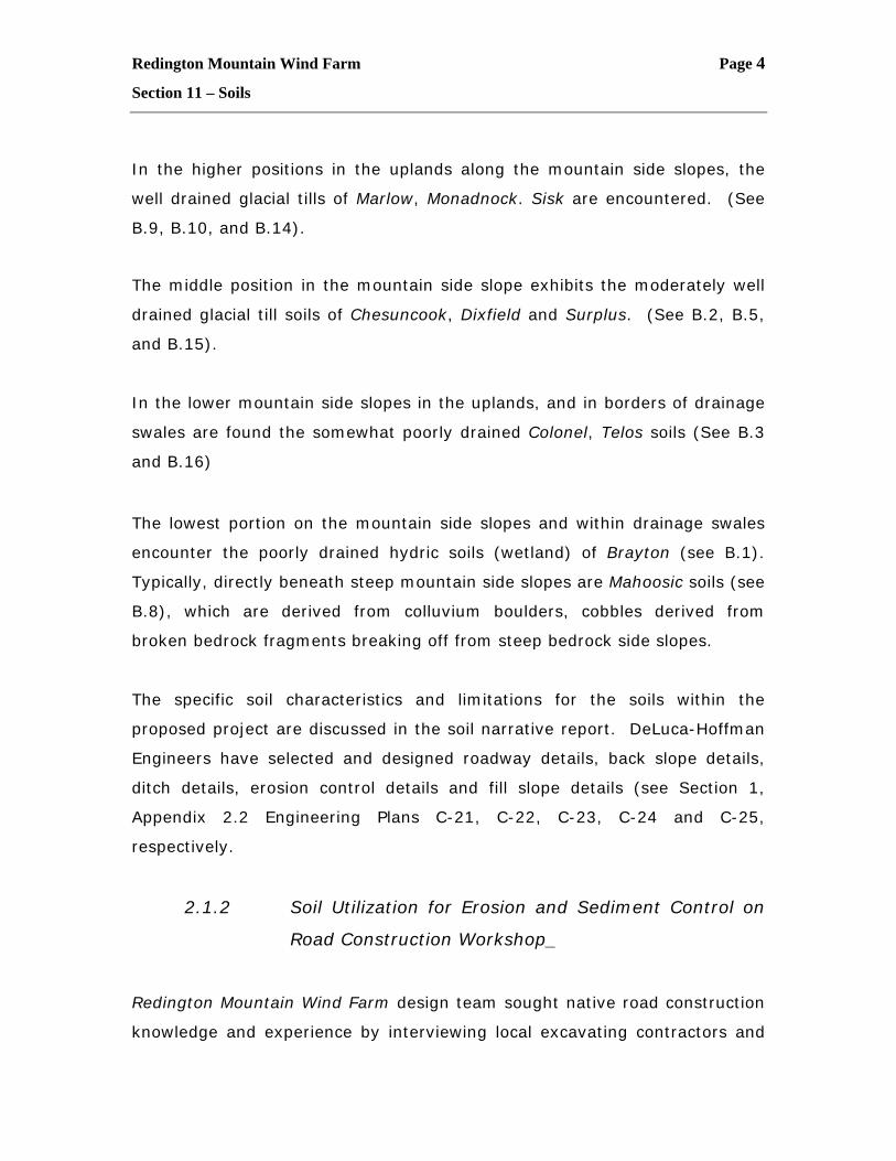
Photo 2: Existing high elevation road cut at Seven Ponds TWP at 2,600'+/-. Photo illustrates
typical strong surface horizon over glacial basal till substratum. Location not in project area,
however, used as available example of deep road cut in high elevation mountainous area,
exhibiting typical very stony soil surface over firm basal till. Photographer A.F. 11/12/2003.
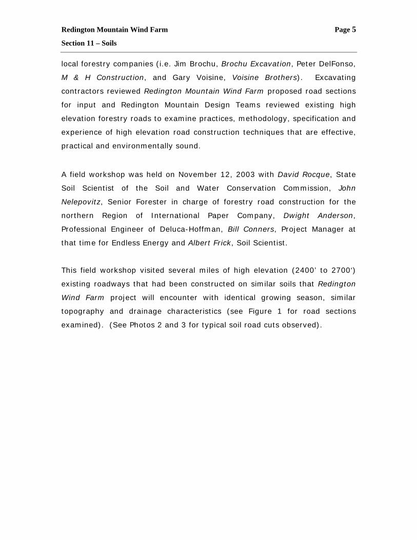
Photo 3: Existing road profile at Seven Ponds TWP at 2,500'+/-. Photo illustrates stony surface
horizon over deep glacial till substratum. Photographer A.F. 11/12/2003.
Redington Mountain Wind Farm Page 7
Section 11 – Soils
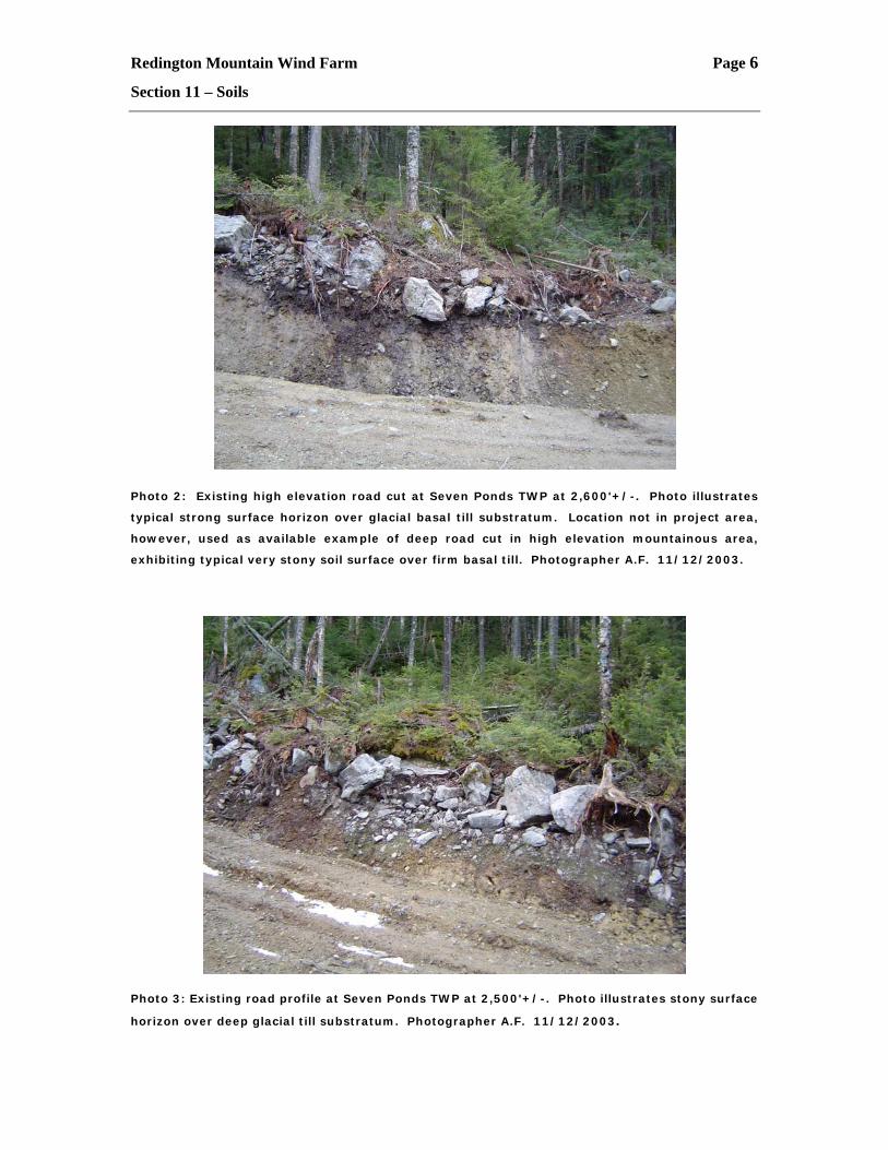
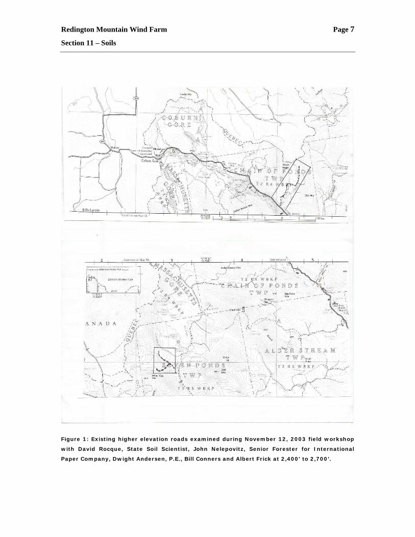
Figure 1: Existing higher elevation roads examined during November 12, 2003 field workshop
with David Rocque, State Soil Scientist, John Nelepovitz, Senior Forester for International
Paper Company, Dwight Andersen, P.E., Bill Conners and Albert Frick at 2,400' to 2,700’.
Redington Mountain Wind Farm Page 8
Section 11 – Soils
Redington Wind Farm design team, after examining existing high elevation
steep gradient roadways, evaluated techniques that were found to be
effective, and translated and integrated local “know-how” into engineering
specifications, and erosion and sediment control details. Additionally,
DeLuca-Hoffman, S.W. Cole, and Albert Frick Associates provided special
erosion/sediment control methods and road construction methods that will
need to be utilized in special highly sensitive segments of the proposed
roadway.
Redington Mountain Wind Farm Page 9
Section 11 – Soils
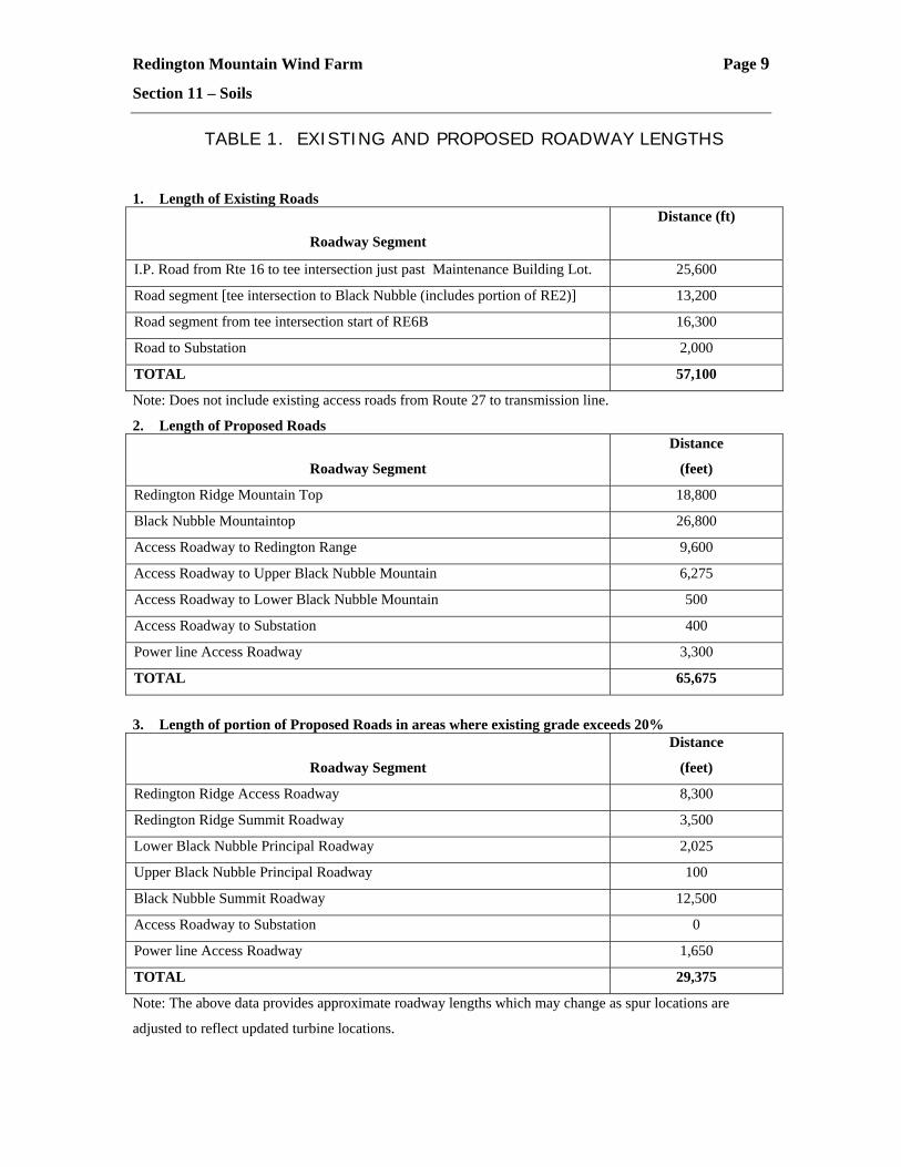
TABLE 1. EXISTING AND PROPOSED ROADWAY LENGTHS
1. Length of Existing Roads
Roadway Segment
Distance (ft)
I.P. Road from Rte 16 to tee intersection just past Maintenance Building Lot. 25,600
Road segment [tee intersection to Black Nubble (includes portion of RE2)] 13,200
Road segment from tee intersection start of RE6B 16,300
Road to Substation 2,000
TOTAL 57,100
Note: Does not include existing access roads from Route 27 to transmission line.
2. Length of Proposed Roads
Roadway Segment
Distance
(feet)
Redington Ridge Mountain Top 18,800
Black Nubble Mountaintop 26,800
Access Roadway to Redington Range 9,600
Access Roadway to Upper Black Nubble Mountain 6,275
Access Roadway to Lower Black Nubble Mountain 500
Access Roadway to Substation 400
Power line Access Roadway 3,300
TOTAL 65,675
3. Length of portion of Proposed Roads in areas where existing grade exceeds 20%
Roadway Segment
Distance
(feet)
Redington Ridge Access Roadway 8,300
Redington Ridge Summit Roadway 3,500
Lower Black Nubble Principal Roadway 2,025
Upper Black Nubble Principal Roadway 100
Black Nubble Summit Roadway 12,500
Access Roadway to Substation 0
Power line Access Roadway 1,650
TOTAL 29,375
Note: The above data provides approximate roadway lengths which may change as spur locations are
adjusted to reflect updated turbine locations.
Redington Mountain Wind Farm Page 10
Section 11 – Soils
3.0 Soil Impact Assessment of Roadway and Wind
Farm Pad Development on Soil Erosion and Sediment
Control
The array of soil characteristics likely to be encountered along with slope
gradients, and soil drainage classes were input into the erosion and sediment
control methodology analyzed by DeLuca-Hoffman Civil Engineers, S.W. Cole
Geotechnical Engineers and Geologists and Albert Frick Associates, Soil
Scientists.
The predominant soil parameters driving the erosion and sediment control
measures are soil drainage, presence of concentrated surface flows (streams,
seeps), soil depth, slope gradient, stoniness, soil textured, soil organics
(thixotrophic) and growing season. Following is a summary of the analysis of
the soil characteristics listed above and the proposed treatments of the
erosion and sediment methods that are proposed to address the issues:
3.1 Soil Drainage/Concentrated Surface Flow (streams,
seeps):
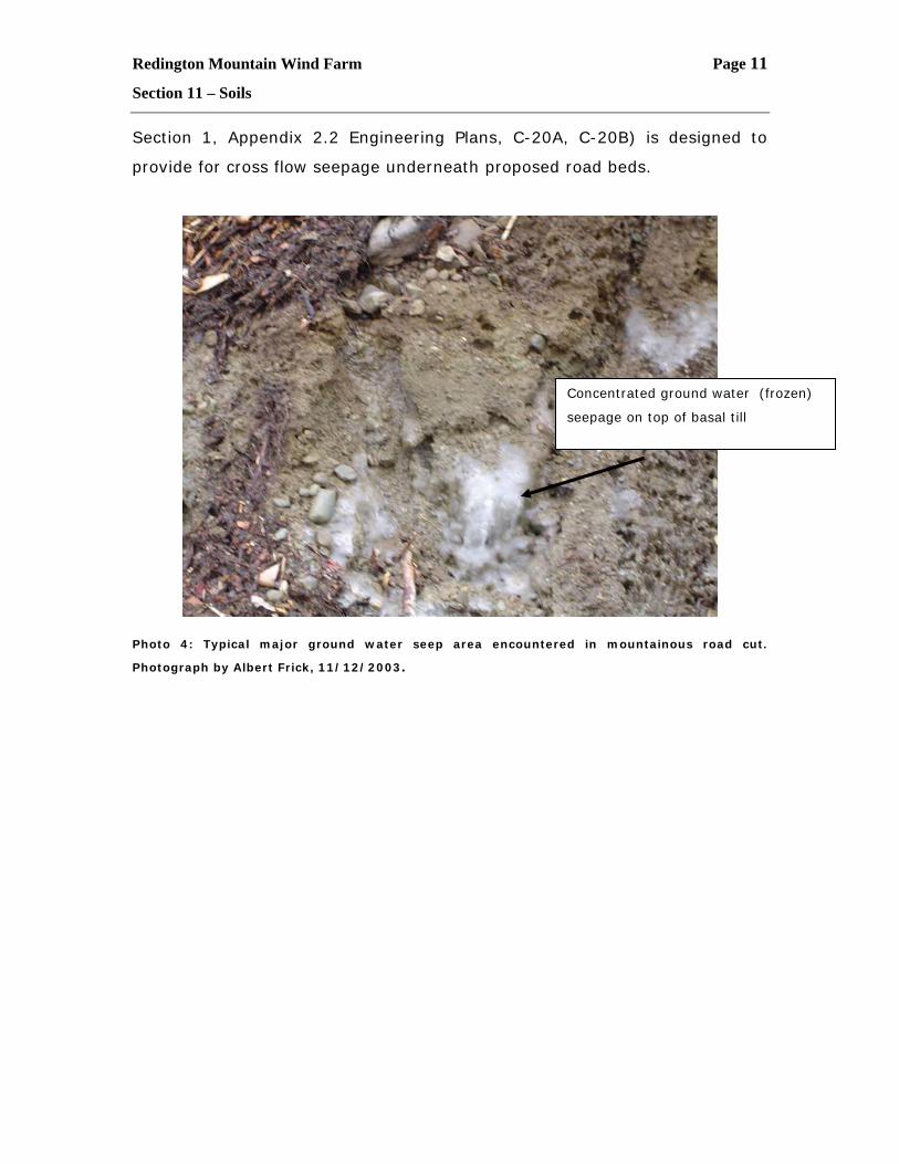
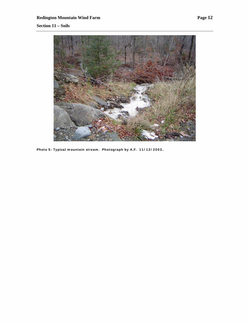
Whenever the proposed roadway cross-cut intercepts a stream, major
ground water seep (spring) or a natural wetland swale(see Photos 4, 5, 6 and
7), a properly sized culvert, of the correct diameter, will be installed to
collect and channel the flow from above the roadway and convey it directly
downslope to be a proper outlet with appropriate stabilization (e.g. plunge
pool, armored rip-rapped channel, etc.). (See Section 1, Appendiz 2.2
Engineering Plan C-21, C-22, C-23, C-24 details).
The proposed road will be intercepting natural slope drainage, in order to
maintain as much natural sheet flow as practical. Cross drainage detail (see
Redington Mountain Wind Farm Page 11
Section 11 – Soils
Section 1, Appendix 2.2 Engineering Plans, C-20A, C-20B) is designed to
provide for cross flow seepage underneath proposed road beds.
Photo 4: Typical major ground water seep area encountered in mountainous road cut.
Photograph by Albert Frick, 11/12/2003.
Concentrated ground water (frozen)
seepage on top of basal till
Redington Mountain Wind Farm Page 12
Section 11 – Soils
Photo 5: Typical mountain stream. Photograph by A.F. 11/12/2003.
Redington Mountain Wind Farm Page 13
Section 11 – Soils
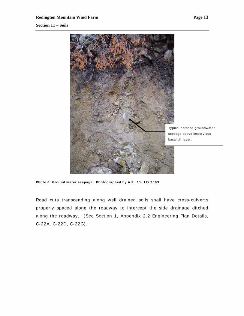
Photo 6: Ground water seepage. Photographed by A.F. 11/12/2003.
Road cuts transcending along well drained soils shall have cross-culverts
properly spaced along the roadway to intercept the side drainage ditched
along the roadway. (See Section 1, Appendix 2.2 Engineering Plan Details,
C-22A, C-22D, C-22G).
Typical perched groundwater
seepage above impervious
basal till layer.
Redington Mountain Wind Farm Page 14
Section 11 – Soils
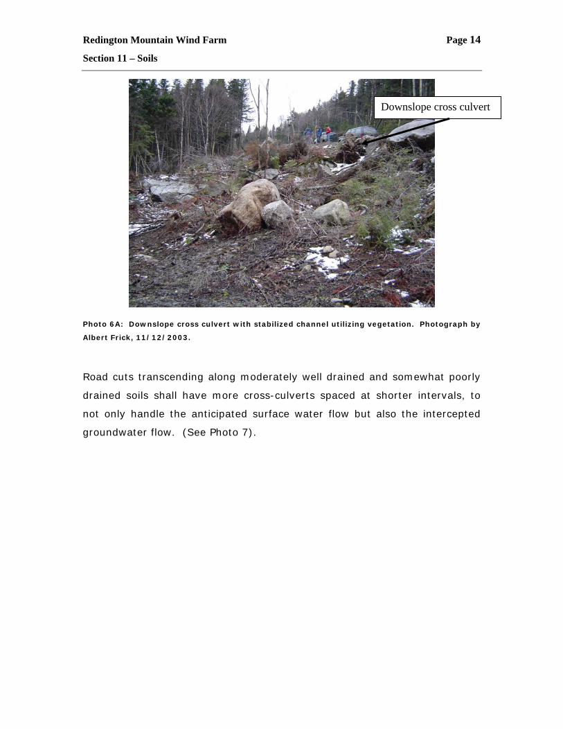
Photo 6A: Downslope cross culvert with stabilized channel utilizing vegetation. Photograph by
Albert Frick, 11/12/2003.
Road cuts transcending along moderately well drained and somewhat poorly
drained soils shall have more cross-culverts spaced at shorter intervals, to
not only handle the anticipated surface water flow but also the intercepted
groundwater flow. (See Photo 7).
Downslope cross culvert
Redington Mountain Wind Farm Page 15
Section 11 – Soils
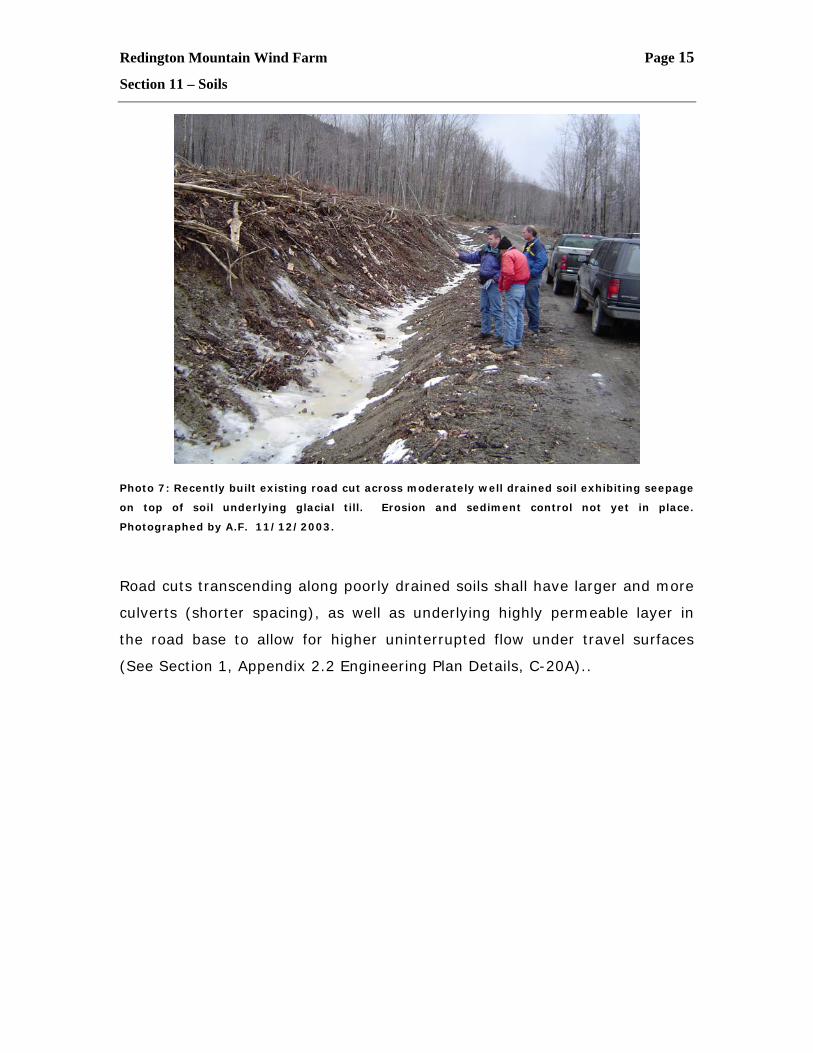
Photo 7: Recently built existing road cut across moderately well drained soil exhibiting seepage
on top of soil underlying glacial till. Erosion and sediment control not yet in place.
Photographed by A.F. 11/12/2003.
Road cuts transcending along poorly drained soils shall have larger and more
culverts (shorter spacing), as well as underlying highly permeable layer in
the road base to allow for higher uninterrupted flow under travel surfaces
(See Section 1, Appendix 2.2 Engineering Plan Details, C-20A)..
Redington Mountain Wind Farm Page 16
Section 11 – Soils
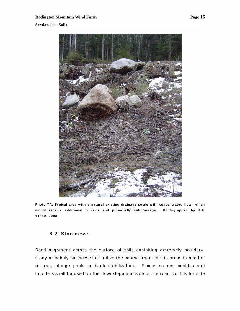
Photo 7A: Typical area with a natural existing drainage swale with concentrated flow, which
would receive additional culverts and potentially subdrainage. Photographed by A.F.
11/12/2003.
3.2 Stoniness:
Road alignment across the surface of soils exhibiting extremely bouldery,
stony or cobbly surfaces shall utilize the coarse fragments in areas in need of
rip rap, plunge pools or bank stabilization. Excess stones, cobbles and
boulders shall be used on the downslope and side of the road cut fills for side
Redington Mountain Wind Farm Page 17
Section 11 – Soils
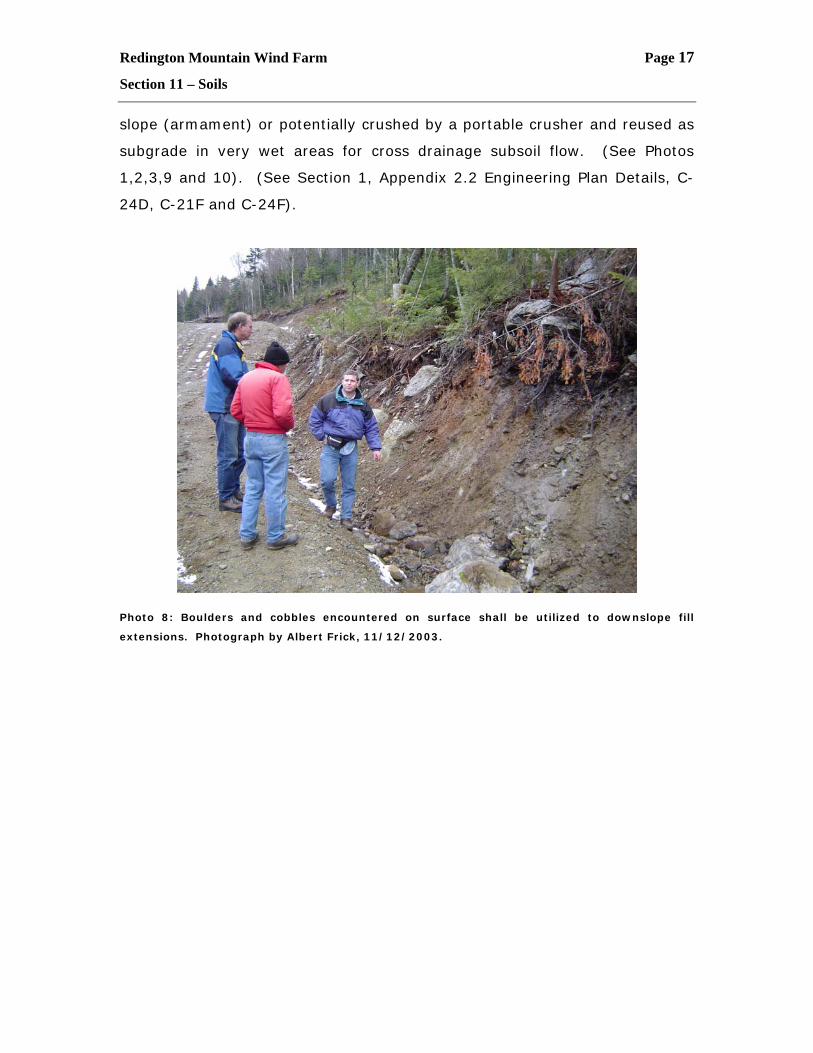
slope (armament) or potentially crushed by a portable crusher and reused as
subgrade in very wet areas for cross drainage subsoil flow. (See Photos
1,2,3,9 and 10). (See Section 1, Appendix 2.2 Engineering Plan Details, C-
24D, C-21F and C-24F).
Photo 8: Boulders and cobbles encountered on surface shall be utilized to downslope fill
extensions. Photograph by Albert Frick, 11/12/2003.
Redington Mountain Wind Farm Page 18
Section 11 – Soils
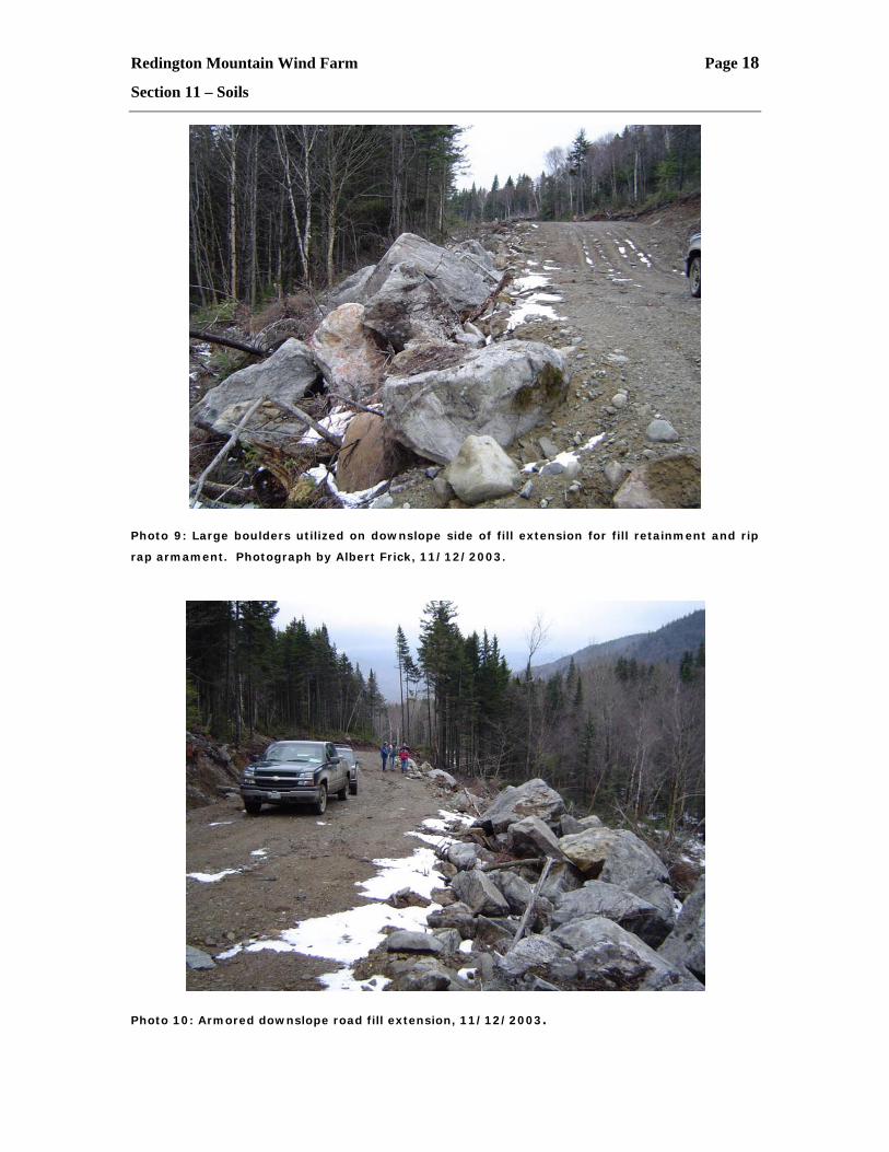
Photo 9: Large boulders utilized on downslope side of fill extension for fill retainment and rip
rap armament. Photograph by Albert Frick, 11/12/2003.
Photo 10: Armored downslope road fill extension, 11/12/2003.
Redington Mountain Wind Farm Page 19
Section 11 – Soils
3.3 Slope Gradient
Proper roadway is designed to meet with specific required grades, turning
radii, widths, and land bearings to allow the turbine blades and parts to be
transported to the ridge tops (See Section 1, Appendix 2.2 Engineering Plan
Details, C-20E). Long term use will be for maintenance and potential
educational visitor tours. Road grade cannot exceed 14% for excessive
lengths. Proposed road is designed to utilize the shortest length of roads to
accomplish the design goals, while avoiding environmentally sensitive areas.
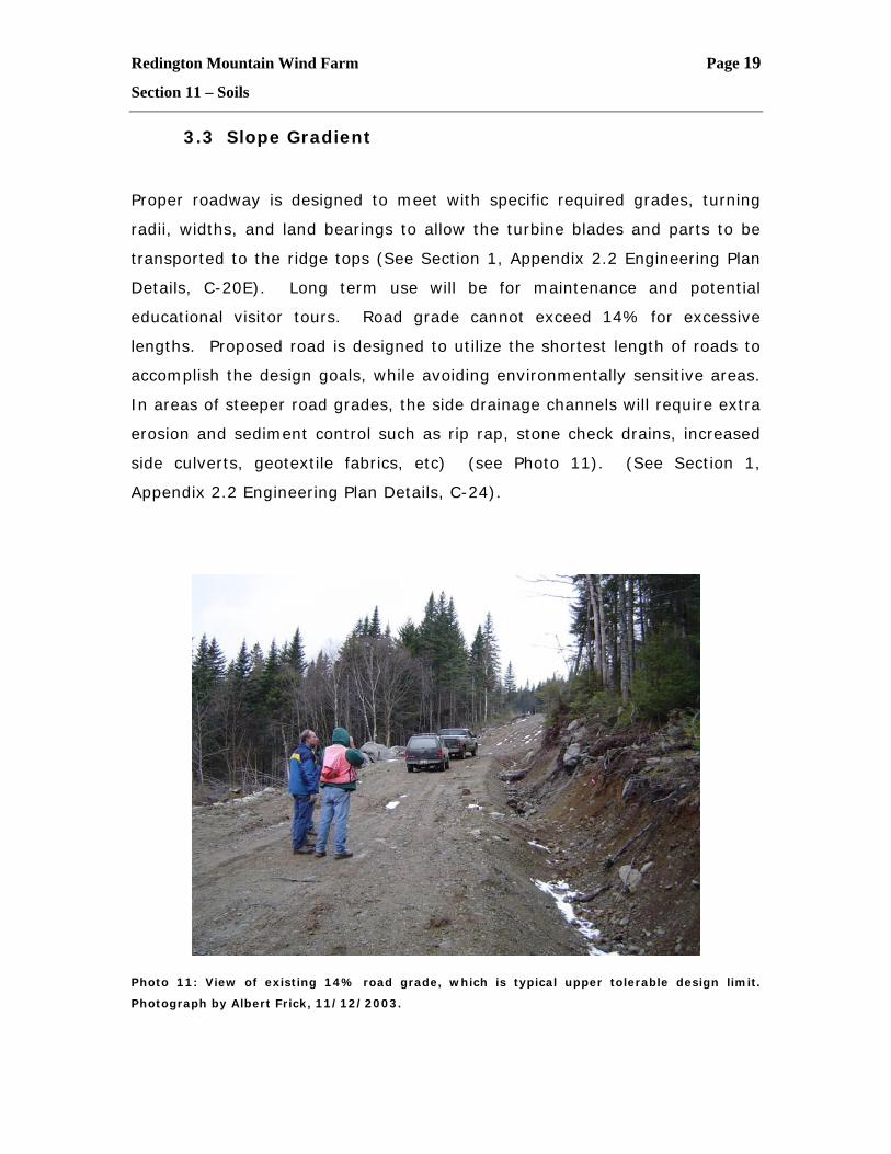
In areas of steeper road grades, the side drainage channels will require extra
erosion and sediment control such as rip rap, stone check drains, increased
side culverts, geotextile fabrics, etc) (see Photo 11). (See Section 1,
Appendix 2.2 Engineering Plan Details, C-24).
Photo 11: View of existing 14% road grade, which is typical upper tolerable design limit.
Photograph by Albert Frick, 11/12/2003.
Redington Mountain Wind Farm Page 20
Section 11 – Soils
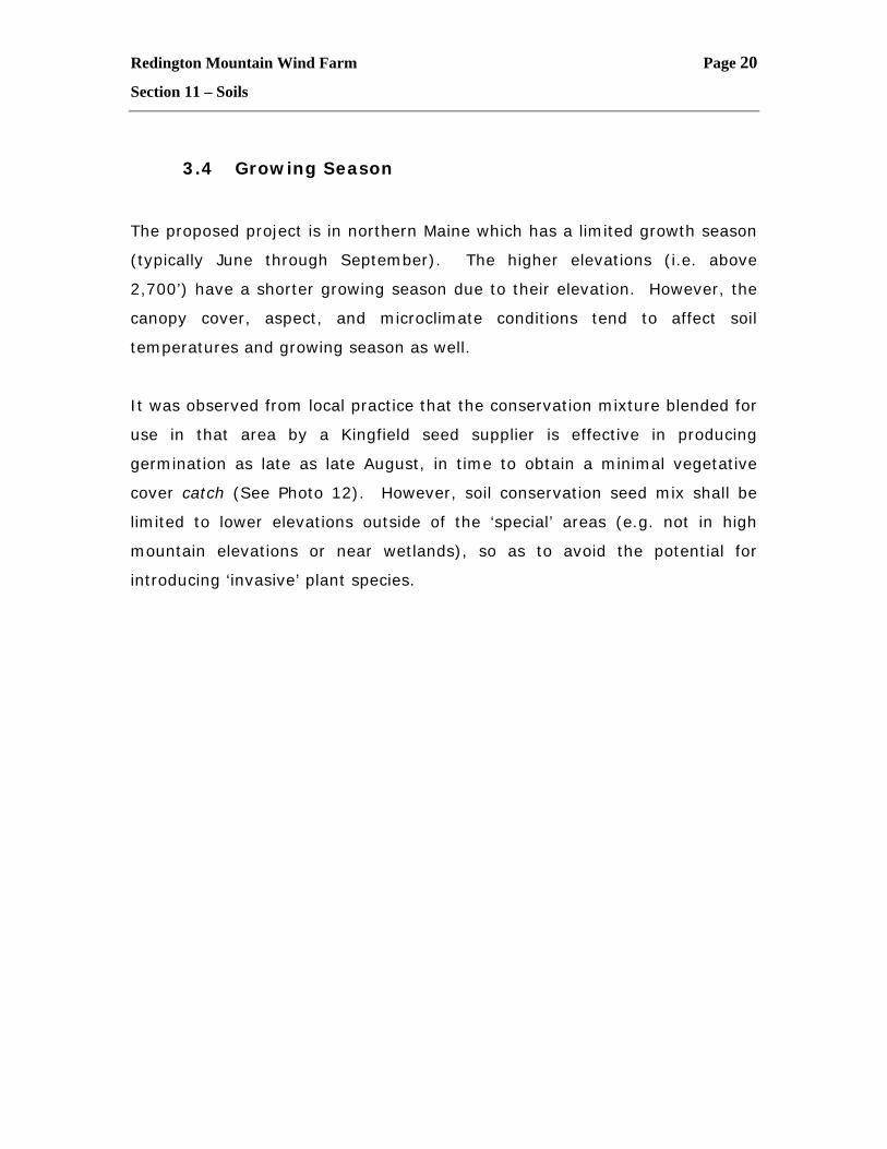
3.4 Growing Season
The proposed project is in northern Maine which has a limited growth season
(typically June through September). The higher elevations (i.e. above
2,700’) have a shorter growing season due to their elevation. However, the
canopy cover, aspect, and microclimate conditions tend to affect soil
temperatures and growing season as well.
It was observed from local practice that the conservation mixture blended for
use in that area by a Kingfield seed supplier is effective in producing
germination as late as late August, in time to obtain a minimal vegetative
cover catch (See Photo 12). However, soil conservation seed mix shall be
limited to lower elevations outside of the ‘special’ areas (e.g. not in high
mountain elevations or near wetlands), so as to avoid the potential for
introducing ‘invasive’ plant species.
Redington Mountain Wind Farm Page 21
Section 11 – Soils
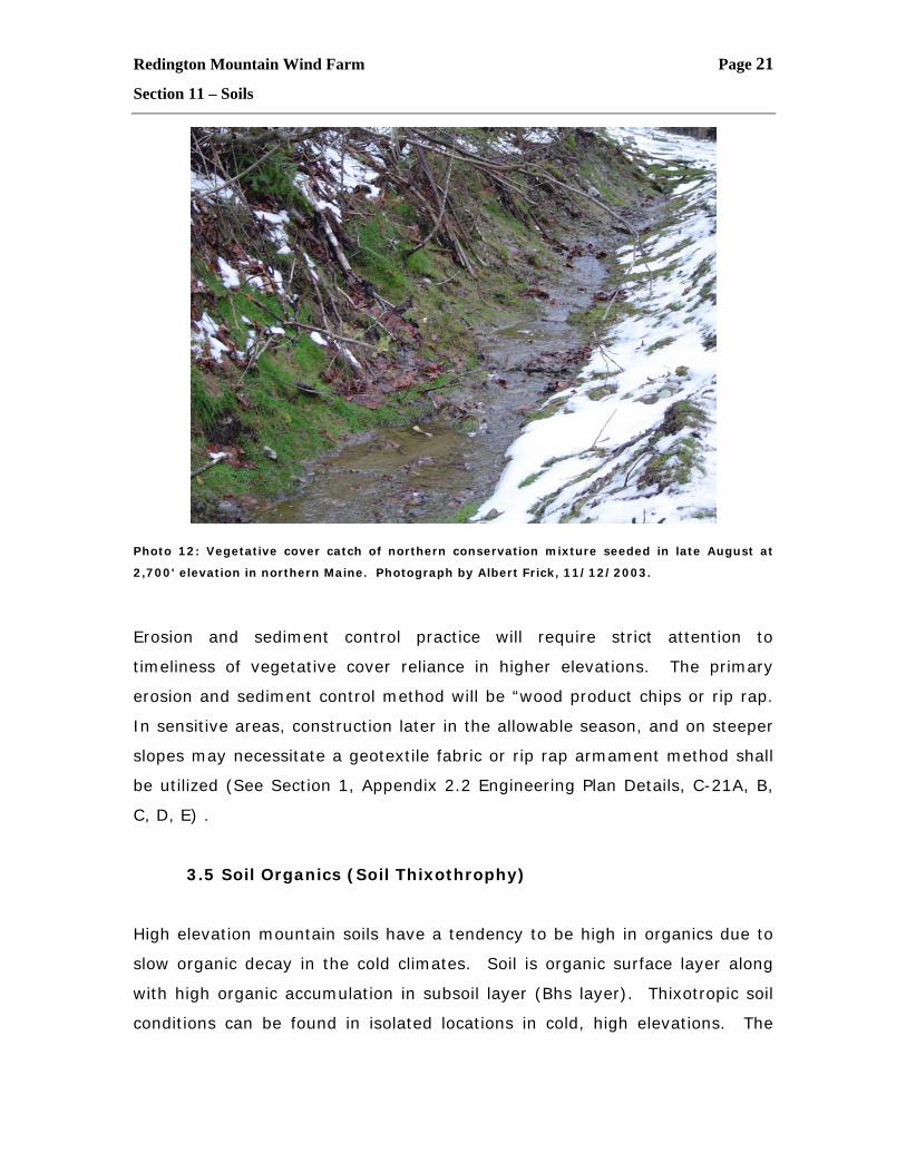
Photo 12: Vegetative cover catch of northern conservation mixture seeded in late August at
2,700' elevation in northern Maine. Photograph by Albert Frick, 11/12/2003.
Erosion and sediment control practice will require strict attention to
timeliness of vegetative cover reliance in higher elevations. The primary
erosion and sediment control method will be “wood product chips or rip rap.
In sensitive areas, construction later in the allowable season, and on steeper
slopes may necessitate a geotextile fabric or rip rap armament method shall
be utilized (See Section 1, Appendix 2.2 Engineering Plan Details, C-21A, B,
C, D, E) .
3.5 Soil Organics (Soil Thixothrophy)
High elevation mountain soils have a tendency to be high in organics due to
slow organic decay in the cold climates. Soil is organic surface layer along
with high organic accumulation in subsoil layer (Bhs layer). Thixotropic soil
conditions can be found in isolated locations in cold, high elevations. The
Redington Mountain Wind Farm Page 22
Section 11 – Soils
term “smeary” is used by NRCS to characterize soil materials that are
thixotropic. A NRCS field test for thixotrophic soil is:
“To press a bit of wet soil between thumb and forefinger; at first
it resists deformation, having some rigidity, or elasticity, or
both; under increasing pressure, the soil can be molded and
deformed; under greater pressure, suddenly the soil changes
from a plastic solid to a liquid, and the fingers skid. After the
soil smears in this fashion, usually free water can be seen on
the fingers. In a matter of a second or two, the liquefied soil
sets again to its original soil state”.
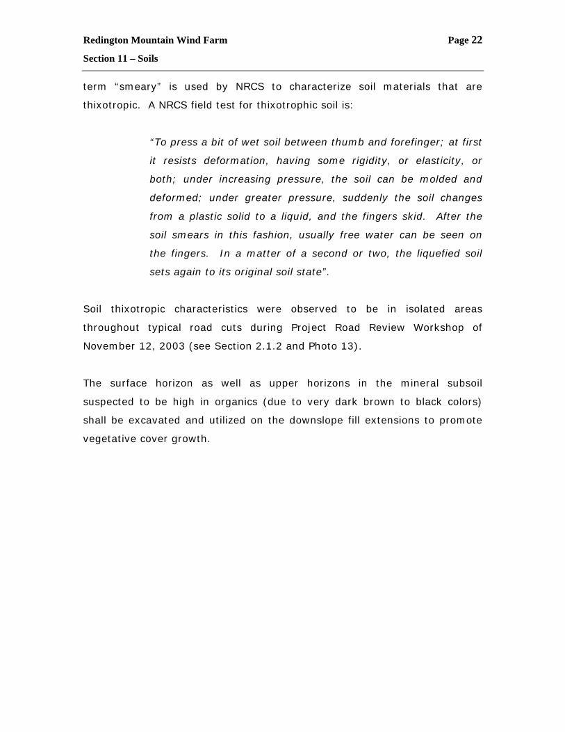
Soil thixotropic characteristics were observed to be in isolated areas
throughout typical road cuts during Project Road Review Workshop of
November 12, 2003 (see Section 2.1.2 and Photo 13).
The surface horizon as well as upper horizons in the mineral subsoil
suspected to be high in organics (due to very dark brown to black colors)
shall be excavated and utilized on the downslope fill extensions to promote
vegetative cover growth.
Redington Mountain Wind Farm Page 23
Section 11 – Soils
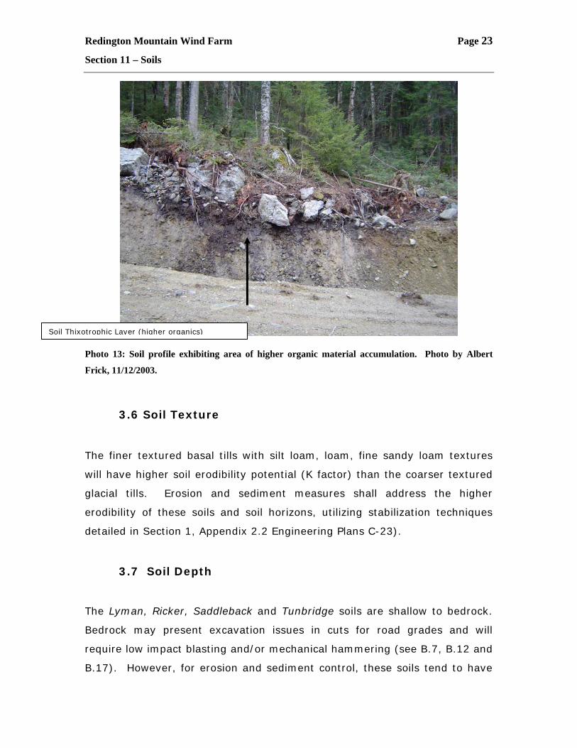
Photo 13: Soil profile exhibiting area of higher organic material accumulation. Photo by Albert
Frick, 11/12/2003.
3.6 Soil Texture
The finer textured basal tills with silt loam, loam, fine sandy loam textures
will have higher soil erodibility potential (K factor) than the coarser textured
glacial tills. Erosion and sediment measures shall address the higher
erodibility of these soils and soil horizons, utilizing stabilization techniques
detailed in Section 1, Appendix 2.2 Engineering Plans C-23).
3.7 Soil Depth
The Lyman, Ricker, Saddleback and Tunbridge soils are shallow to bedrock.
Bedrock may present excavation issues in cuts for road grades and will
require low impact blasting and/or mechanical hammering (see B.7, B.12 and
B.17). However, for erosion and sediment control, these soils tend to have
Soil Thixotrophic Layer (higher organics)
Redington Mountain Wind Farm Page 24
Section 11 – Soils
ess erodibility due to the absence of soil fragments and the presence of
bedrock. These soils types are typically on the higher ridge tops and higher
elevations. The lack of soil sediments and the reduction in watershed area
(being on the top of the watershed) reduce the erosion potential.
3.8 Construction/Remediation/Repair
The project engineer overseeing the project, and the excavating company
overseeing construction of the project shall apply the appropriate erosion
control details, fill slope details, back slope details, roadway details and ditch
details, where applicable. (See Section 1, Appendix 2.2 Engineering Plan
Details, C-20, C-21, C-22, C-23, C-24).
Any limited areas that are found to be ineffective by the erosion and
sediment method applied, either due to ineffectiveness of erosion and
sediment application, inappropriate timing, or combination will be
immediately repaired. The erosion and sediment method shall be
reevaluated, and reapplied at the first available opportunity. Consideration
of more effective treatment or improved timing may be necessary. Areas of
pre-existing access roadways shall be inspected for erodibility and repaired, if
present, with appropriate techniques detailed in (See Section 1, Appendix 2.2
Engineering Plan Details, C-21, C-22, C-23, C-24.
4.0 Literature Cited
Guidelines for Maine Certified Soil Scientists for Soil Identification and Mapping.
Maine Associates of Professional Soil Scientists, February 1995, as amended.
National Resource Conservation Services, Soil Survey Field Work Sheets. Franklin
County, Maine.
Redington Mountain Wind Farm Page 25
Section 11 – Soils
Soil Series of Maine, Soil Descriptions, Maine Associates of Professional Soil
Scientists, USDA Soil Conservation Services.
Soil Series of Maine, Soil Interpretations, Maine Associates of Professional Soil
Scientists, USDA Soil Conservation Services.
Soil Taxonomy, A Basic System of Soil Classification for Making and Interpreting
Soil Surveys, December 1975 as amended.

Redington Mountain Wind Farm Page 26
Section 11 – Soils
APPENDICES
A Soil Maps
A-1 Project Area
A-2 Maintenance Building
B Soil Narrative Report
C Letters of Correspondence
D Additional Photographs
Redington Mountain Wind Farm Page 27
Section 11 – Soils
Appendix A
Soils Maps
A-1 Project Area
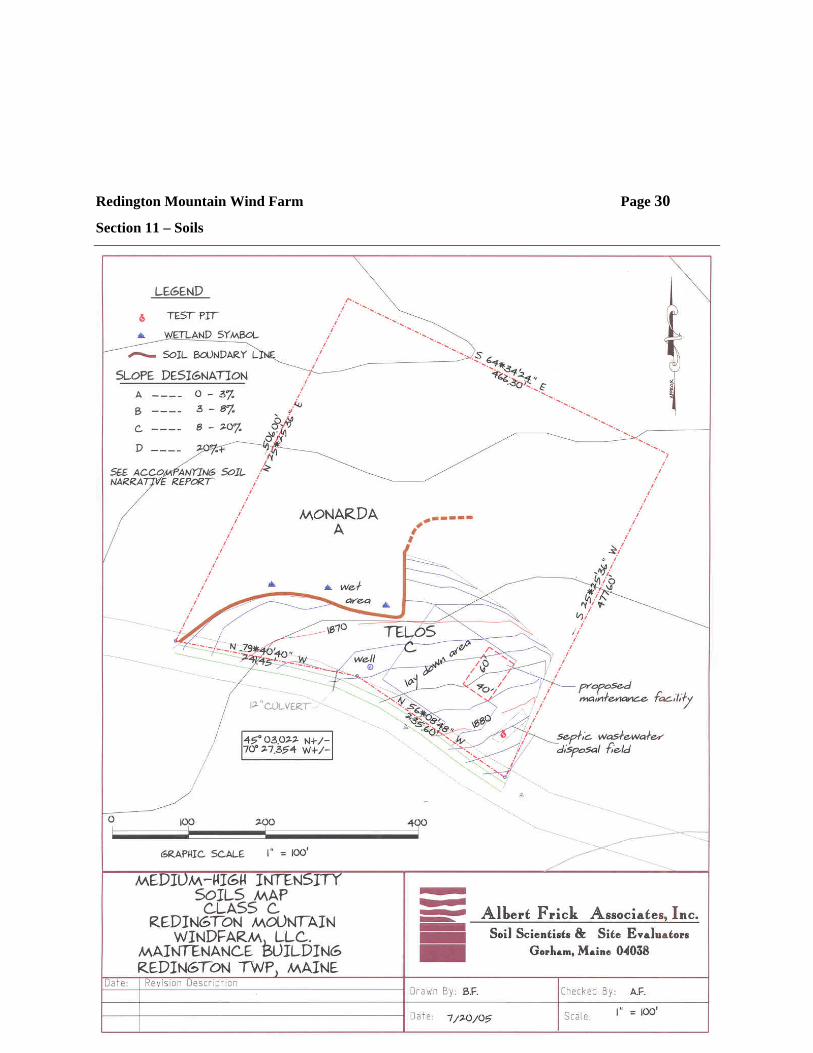
A-2 Maintenance Building
Redington Mountain Wind Farm Page 28
Section 11 – Soils
A-1
Project Area
[NOTE: 2x3 hard copy to be scanned and inserted here as .PDF file]
Redington Mountain Wind Farm Page 29
Section 11 – Soils
A-2
Maintenance Building
Redington Mountain Wind Farm Page 30
Section 11 – Soils
Redington Mountain Wind Farm Page 31
Section 11 – Soils
APPENDIX B
Soil Narrative Report
Redington Mountain Wind Farm Page 32
Section 11 – Soils
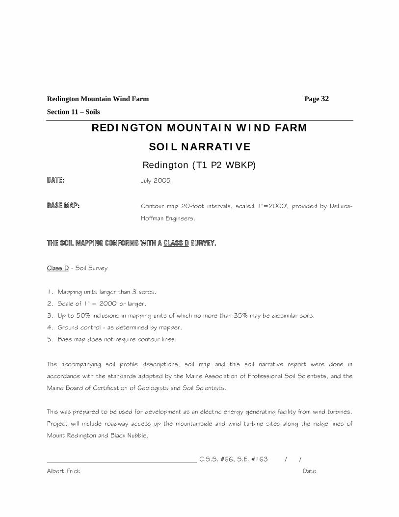
REDINGTON MOUNTAIN WIND FARM
SOIL NARRATIVE
Redington (T1 P2 WBKP)
DATE: July 2005
BASE MAP: Contour map 20-foot intervals, scaled 1"=2000', provided by DeLuca-
Hoffman Engineers.
THE SOIL MAPPING CONFORMS WITH A CLASS D SURVEY.
Class D - Soil Survey
1. Mapping units larger than 3 acres.
2. Scale of 1" = 2000' or larger.
3. Up to 50% inclusions in mapping units of which no more than 35% may be dissimilar soils.
4. Ground control - as determined by mapper.
5. Base map does not require contour lines.
The accompanying soil profile descriptions, soil map and this soil narrative report were done in
accordance with the standards adopted by the Maine Association of Professional Soil Scientists, and the
Maine Board of Certification of Geologists and Soil Scientists.
This was prepared to be used for development as an electric energy generating facility from wind turbines.
Project will include roadway access up the mountainside and wind turbine sites along the ridge lines of
Mount Redington and Black Nubble.
______________________________________________ C.S.S. #66, S.E. #163 / /
Albert Frick Date
Redington Mountain Wind Farm Page 33
Section 11 – Soils
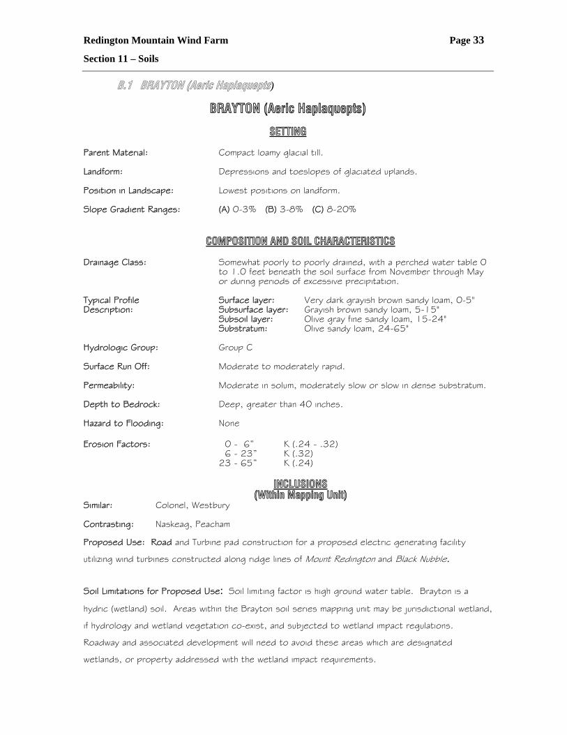
B.1 BRAYTON (Aeric Haplaquepts)
BRAYTON (Aeric Haplaquepts)
SETTING Parent Material: Compact loamy glacial till. Landform: Depressions and toeslopes of glaciated uplands. Position in Landscape: Lowest positions on landform. Slope Gradient Ranges: (A) 0-3% (B) 3-8% (C) 8-20% COMPOSITION AND SOIL CHARACTERISTICS Drainage Class: Somewhat poorly to poorly drained, with a perched water table 0
to 1.0 feet beneath the soil surface from November through May or during periods of excessive precipitation.
Typical Profile Surface layer: Very dark grayish brown sandy loam, 0-5" Description: Subsurface layer: Grayish brown sandy loam, 5-15"
Subsoil layer: Olive gray fine sandy loam, 15-24" Substratum: Olive sandy loam, 24-65"
Hydrologic Group: Group C Surface Run Off: Moderate to moderately rapid. Permeability: Moderate in solum, moderately slow or slow in dense substratum. Depth to Bedrock: Deep, greater than 40 inches. Hazard to Flooding: None Erosion Factors: 0 - 6” K (.24 - .32) 6 - 23” K (.32) 23 - 65” K (.24) INCLUSIONS (Within Mapping Unit) Similar: Colonel, Westbury Contrasting: Naskeag, Peacham Proposed Use: Road and Turbine pad construction for a proposed electric generating facility
utilizing wind turbines constructed along ridge lines of Mount Redington and Black Nubble.
Soil Limitations for Proposed Use: Soil limiting factor is high ground water table. Brayton is a
hydric (wetland) soil. Areas within the Brayton soil series mapping unit may be jurisdictional wetland,
if hydrology and wetland vegetation co-exist, and subjected to wetland impact regulations.
Roadway and associated development will need to avoid these areas which are designated
wetlands, or property addressed with the wetland impact requirements.
Redington Mountain Wind Farm Page 34
Section 11 – Soils
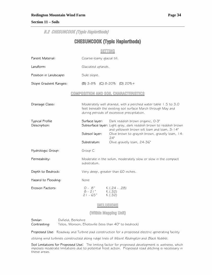
B.2 CHESUNCOOK (Typic Haplorthods)
CHESUNCOOK (Typic Haplorthods)
SETTING
Parent Material: Coarse-loamy glacial till. Landform: Glaciated uplands. Position in Landscape: Side slope. Slope Gradient Ranges: (B) 3-8% (C) 8-20% (D) 20%+
COMPOSITION AND SOIL CHARACTERISTICS Drainage Class: Moderately well drained, with a perched water table 1.5 to 3.0
feet beneath the existing soil surface March through May and during periods of excessive precipitation.
Typical Profile Surface layer: Dark reddish brown organic, 0-3"
Description: Subsurface layer: Light gray, dark reddish brown to reddish brown and yellowish brown silt loam and loam, 3-14"
Subsoil layer: Olive brown to grayish brown, gravelly loam, 14-24"
Substratum: Olive gravelly loam, 24-36" Hydrologic Group: Group C Permeability: Moderate in the solum, moderately slow or slow in the compact
substratum. Depth to Bedrock: Very deep, greater than 60 inches. Hazard to Flooding: None Erosion Factors: 0 - 8” K (.24 - .28) 8 - 21” K (.32) 21 - 65” K (.32)
INCLUSIONS
(Within Mapping Unit)
Similar: Dixfield, Berkshire Contrasting: Telos, Monson, Elliotsville (less than 40" to bedrock) Proposed Use: Roadway and Turbine pad construction for a proposed electric generating facility
utilizing wind turbines constructed along ridge lines of Mount Redington and Black Nubble.
Soil Limitations for Proposed Use: The limiting factor for proposed development is wetness, which imposes moderate limitations due to potential frost action. Proposed road ditching is necessary in these areas.
Redington Mountain Wind Farm Page 35
Section 11 – Soils
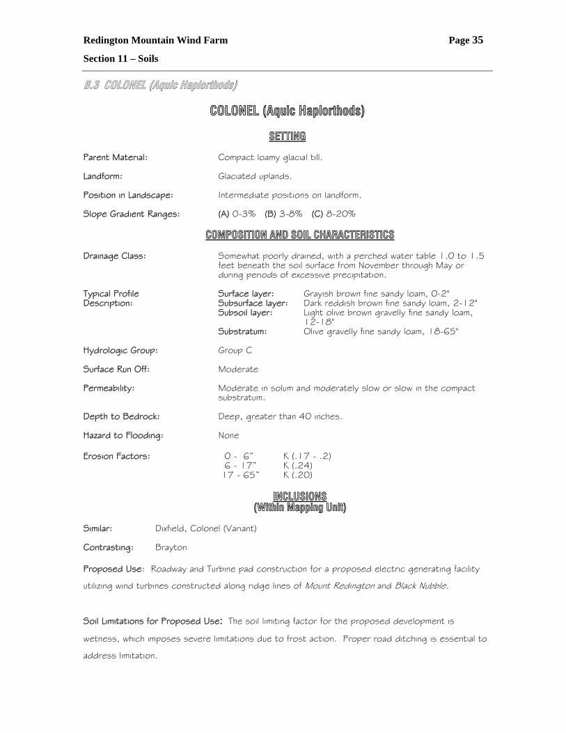
B.3 COLONEL (Aquic Haplorthods)
COLONEL (Aquic Haplorthods)
SETTING Parent Material: Compact loamy glacial till. Landform: Glaciated uplands. Position in Landscape: Intermediate positions on landform. Slope Gradient Ranges: (A) 0-3% (B) 3-8% (C) 8-20% COMPOSITION AND SOIL CHARACTERISTICS Drainage Class: Somewhat poorly drained, with a perched water table 1.0 to 1.5
feet beneath the soil surface from November through May or during periods of excessive precipitation.
Typical Profile Surface layer: Grayish brown fine sandy loam, 0-2" Description: Subsurface layer: Dark reddish brown fine sandy loam, 2-12"
Subsoil layer: Light olive brown gravelly fine sandy loam, 12-18"
Substratum: Olive gravelly fine sandy loam, 18-65" Hydrologic Group: Group C Surface Run Off: Moderate Permeability: Moderate in solum and moderately slow or slow in the compact
substratum. Depth to Bedrock: Deep, greater than 40 inches. Hazard to Flooding: None Erosion Factors: 0 - 6” K (.17 - .2) 6 - 17” K (.24) 17 - 65” K (.20) INCLUSIONS (Within Mapping Unit) Similar: Dixfield, Colonel (Variant) Contrasting: Brayton Proposed Use: Roadway and Turbine pad construction for a proposed electric generating facility
utilizing wind turbines constructed along ridge lines of Mount Redington and Black Nubble.
Soil Limitations for Proposed Use: The soil limiting factor for the proposed development is
wetness, which imposes severe limitations due to frost action. Proper road ditching is essential to
address limitation.
Redington Mountain Wind Farm Page 36
Section 11 – Soils
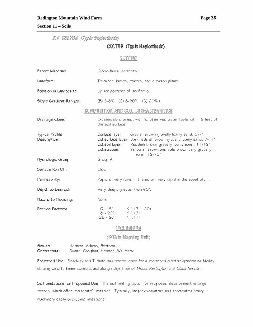
B.4 COLTON (Typic Haplorthods)
COLTON (Typic Haplorthods)
SETTING Parent Material: Glacio-fluvial deposits. Landform: Terraces, kames, eskers, and outwash plains. Position in Landscape: Upper portions of landforms. Slope Gradient Ranges: (B) 3-8% (C) 8-20% (D) 20%+
COMPOSITION AND SOIL CHARACTERISTICS
Drainage Class: Excessively drained, with no observed water table within 6 feet of the soil surface. Typical Profile Surface layer: Grayish brown gravelly loamy sand, 0-7" Description: Subsurface layer: Dark reddish brown gravelly loamy sand, 7-11" Subsoil layer: Reddish brown gravelly loamy sand, 11-16" Substratum: Yellowish brown and pale brown very gravelly
sand, 16-70" Hydrologic Group: Group A Surface Run Off: Slow Permeability: Rapid or very rapid in the solum, very rapid in the substratum. Depth to Bedrock: Very deep, greater than 60". Hazard to Flooding: None Erosion Factors: 0 - 8” K (.17 - .20) 8 - 22” K (.17) 22 - 60” K (.17)
INCLUSIONS
(Within Mapping Unit) Similar: Hermon, Adams, Stetson Contrasting: Duane, Croghan, Hermon, Waumbek Proposed Use: Roadway and Turbine pad construction for a proposed electric generating facility
utilizing wind turbines constructed along ridge lines of Mount Redington and Black Nubble.
Soil Limitations for Proposed Use: The soil limiting factor for proposed development is large
stones, which offer ‘moderate’ limitation. Typically, larger excavators and associated heavy
machinery easily overcome limitations:
Redington Mountain Wind Farm Page 37
Section 11 – Soils
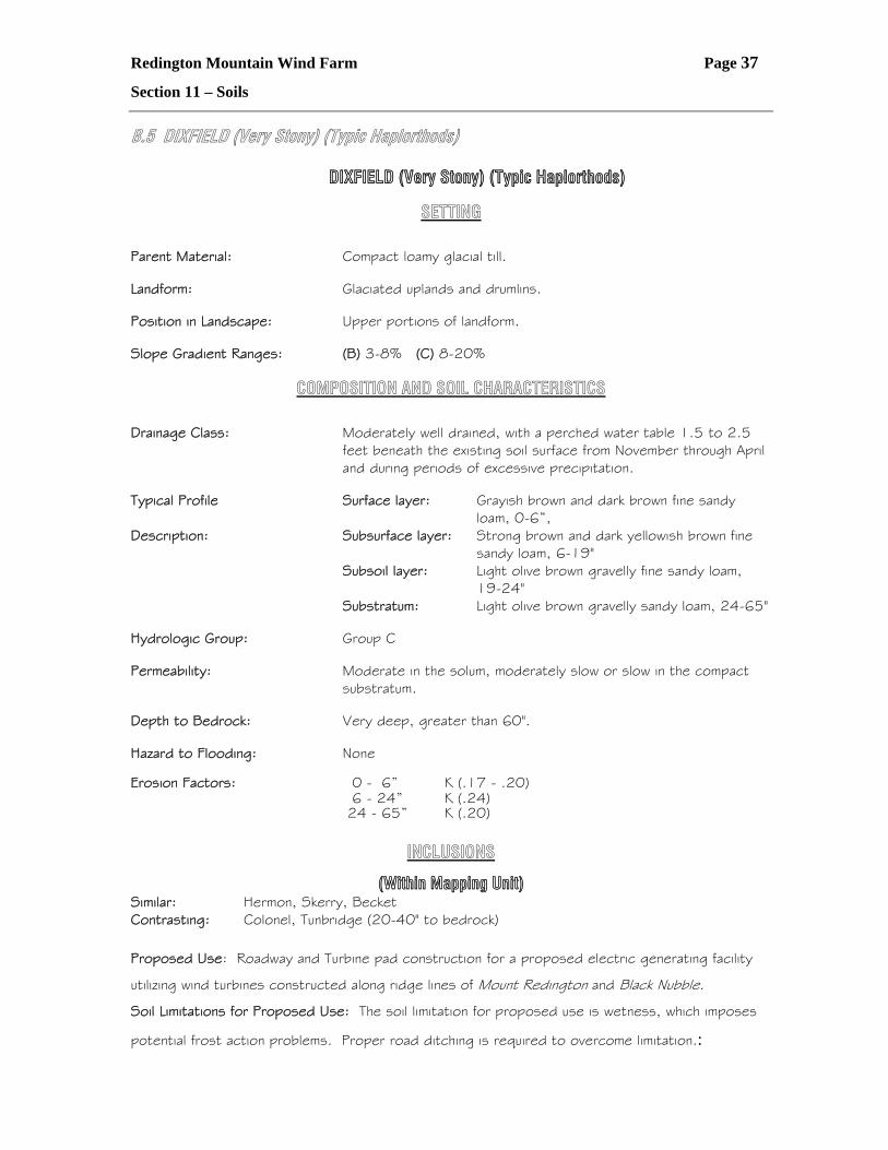
B.5 DIXFIELD (Very Stony) (Typic Haplorthods)
DIXFIELD (Very Stony) (Typic Haplorthods)
SETTING Parent Material: Compact loamy glacial till. Landform: Glaciated uplands and drumlins. Position in Landscape: Upper portions of landform. Slope Gradient Ranges: (B) 3-8% (C) 8-20%
COMPOSITION AND SOIL CHARACTERISTICS Drainage Class: Moderately well drained, with a perched water table 1.5 to 2.5
feet beneath the existing soil surface from November through April and during periods of excessive precipitation.
Typical Profile Surface layer: Grayish brown and dark brown fine sandy
loam, 0-6”, Description: Subsurface layer: Strong brown and dark yellowish brown fine sandy loam, 6-19" Subsoil layer: Light olive brown gravelly fine sandy loam,
19-24" Substratum: Light olive brown gravelly sandy loam, 24-65" Hydrologic Group: Group C Permeability: Moderate in the solum, moderately slow or slow in the compact
substratum. Depth to Bedrock: Very deep, greater than 60". Hazard to Flooding: None Erosion Factors: 0 - 6” K (.17 - .20) 6 - 24” K (.24) 24 - 65” K (.20)
INCLUSIONS
(Within Mapping Unit) Similar: Hermon, Skerry, Becket Contrasting: Colonel, Tunbridge (20-40" to bedrock)
Proposed Use: Roadway and Turbine pad construction for a proposed electric generating facility
utilizing wind turbines constructed along ridge lines of Mount Redington and Black Nubble.
Soil Limitations for Proposed Use: The soil limitation for proposed use is wetness, which imposes
potential frost action problems. Proper road ditching is required to overcome limitation.:
Redington Mountain Wind Farm Page 38
Section 11 – Soils
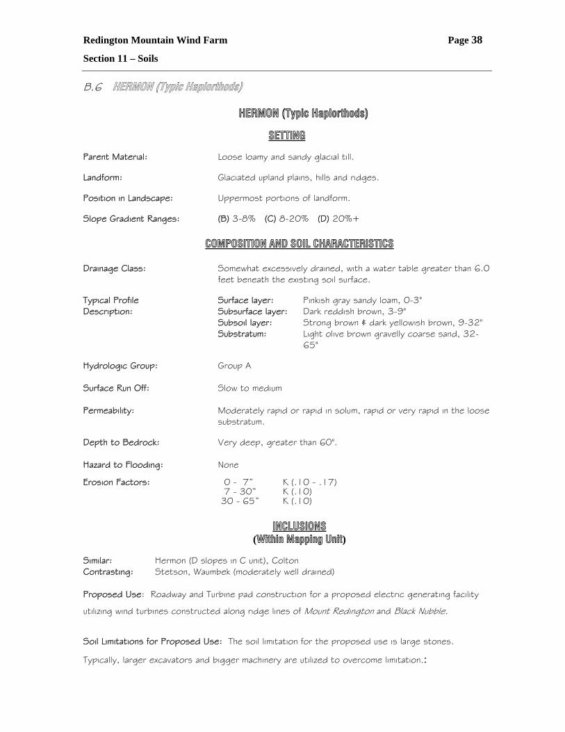
B.6 HERMON (Typic Haplorthods)
HERMON (Typic Haplorthods)
SETTING Parent Material: Loose loamy and sandy glacial till. Landform: Glaciated upland plains, hills and ridges. Position in Landscape: Uppermost portions of landform. Slope Gradient Ranges: (B) 3-8% (C) 8-20% (D) 20%+ COMPOSITION AND SOIL CHARACTERISTICS Drainage Class: Somewhat excessively drained, with a water table greater than 6.0
feet beneath the existing soil surface. Typical Profile Surface layer: Pinkish gray sandy loam, 0-3" Description: Subsurface layer: Dark reddish brown, 3-9" Subsoil layer: Strong brown & dark yellowish brown, 9-32" Substratum: Light olive brown gravelly coarse sand, 32-
65" Hydrologic Group: Group A Surface Run Off: Slow to medium Permeability: Moderately rapid or rapid in solum, rapid or very rapid in the loose
substratum. Depth to Bedrock: Very deep, greater than 60". Hazard to Flooding: None Erosion Factors: 0 - 7” K (.10 - .17) 7 - 30” K (.10) 30 - 65” K (.10)
INCLUSIONS (Within Mapping Unit) Similar: Hermon (D slopes in C unit), Colton Contrasting: Stetson, Waumbek (moderately well drained) Proposed Use: Roadway and Turbine pad construction for a proposed electric generating facility
utilizing wind turbines constructed along ridge lines of Mount Redington and Black Nubble.
Soil Limitations for Proposed Use: The soil limitation for the proposed use is large stones.
Typically, larger excavators and bigger machinery are utilized to overcome limitation.:
Redington Mountain Wind Farm Page 39
Section 11 – Soils
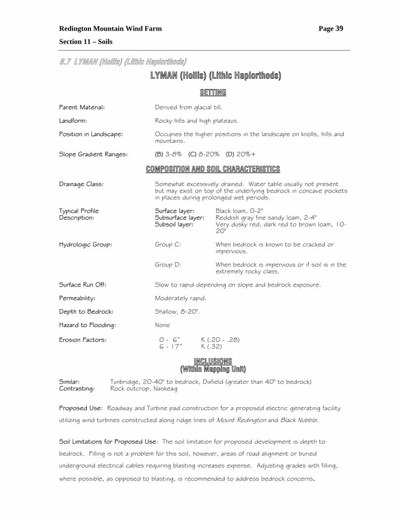
B.7 LYMAN (Hollis) (Lithic Haplorthods)
LYMAN (Hollis) (Lithic Haplorthods)
SETTING Parent Material: Derived from glacial till. Landform: Rocky hills and high plateaus. Position in Landscape: Occupies the higher positions in the landscape on knolls, hills and
mountains. Slope Gradient Ranges: (B) 3-8% (C) 8-20% (D) 20%+ COMPOSITION AND SOIL CHARACTERISTICS Drainage Class: Somewhat excessively drained. Water table usually not present
but may exist on top of the underlying bedrock in concave pockets in places during prolonged wet periods.
Typical Profile Surface layer: Black loam, 0-2" Description: Subsurface layer: Reddish gray fine sandy loam, 2-4"
Subsoil layer: Very dusky red, dark red to brown loam, 10-20"
Hydrologic Group: Group C: When bedrock is known to be cracked or
impervious.
Group D: When bedrock is impervious or if soil is in the extremely rocky class.
Surface Run Off: Slow to rapid depending on slope and bedrock exposure. Permeability: Moderately rapid. Depth to Bedrock: Shallow, 8-20". Hazard to Flooding: None Erosion Factors: 0 - 6” K (.20 - .28) 6 - 17” K (.32) INCLUSIONS (Within Mapping Unit) Similar: Tunbridge, 20-40" to bedrock, Dixfield (greater than 40" to bedrock) Contrasting: Rock outcrop, Naskeag
Proposed Use: Roadway and Turbine pad construction for a proposed electric generating facility
utilizing wind turbines constructed along ridge lines of Mount Redington and Black Nubble.
Soil Limitations for Proposed Use: The soil limitation for proposed development is depth to
bedrock. Filling is not a problem for this soil, however, areas of road alignment or buried
underground electrical cables requiring blasting increases expense. Adjusting grades with filling,
where possible, as opposed to blasting, is recommended to address bedrock concerns.
Redington Mountain Wind Farm Page 40
Section 11 – Soils
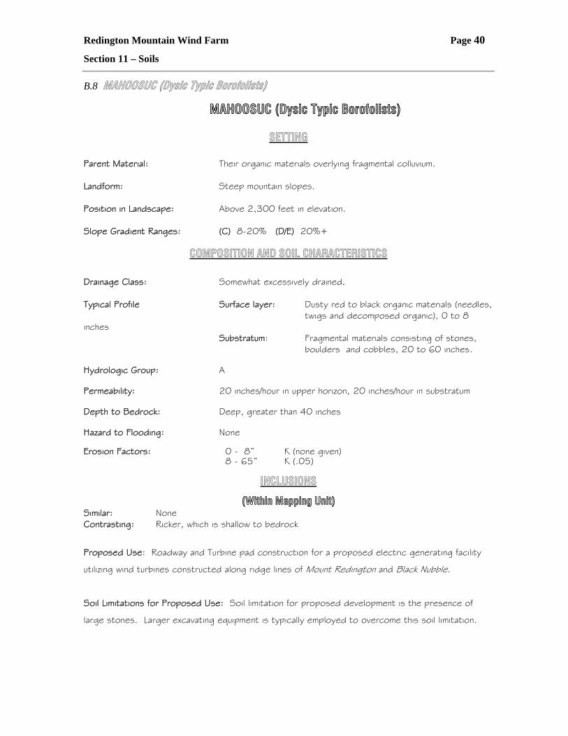
B.8 MAHOOSUC (Dysic Typic Borofolists)
MAHOOSUC (Dysic Typic Borofolists)
SETTING
Parent Material: Their organic materials overlying fragmental colluvium. Landform: Steep mountain slopes. Position in Landscape: Above 2,300 feet in elevation. Slope Gradient Ranges: (C) 8-20% (D/E) 20%+
COMPOSITION AND SOIL CHARACTERISTICS
Drainage Class: Somewhat excessively drained. Typical Profile Surface layer: Dusty red to black organic materials (needles, twigs and decomposed organic), 0 to 8 inches Substratum: Fragmental materials consisting of stones, boulders and cobbles, 20 to 60 inches. Hydrologic Group: A Permeability: 20 inches/hour in upper horizon, 20 inches/hour in substratum Depth to Bedrock: Deep, greater than 40 inches Hazard to Flooding: None Erosion Factors: 0 - 8” K (none given) 8 - 65” K (.05)
INCLUSIONS
(Within Mapping Unit) Similar: None Contrasting: Ricker, which is shallow to bedrock
Proposed Use: Roadway and Turbine pad construction for a proposed electric generating facility
utilizing wind turbines constructed along ridge lines of Mount Redington and Black Nubble.
Soil Limitations for Proposed Use: Soil limitation for proposed development is the presence of
large stones. Larger excavating equipment is typically employed to overcome this soil limitation.
Redington Mountain Wind Farm Page 41
Section 11 – Soils
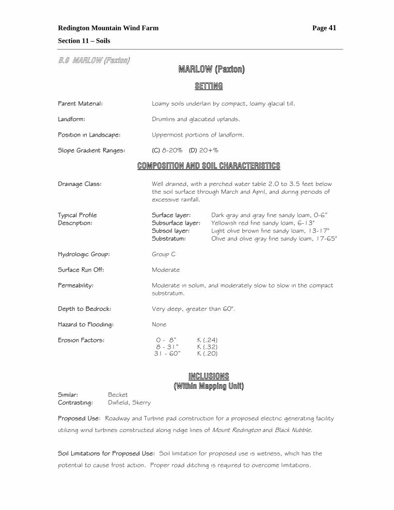
B.9 MARLOW (Paxton) MARLOW (Paxton)
SETTING Parent Material: Loamy soils underlain by compact, loamy glacial till. Landform: Drumlins and glaciated uplands. Position in Landscape: Uppermost portions of landform. Slope Gradient Ranges: (C) 8-20% (D) 20+%
COMPOSITION AND SOIL CHARACTERISTICS Drainage Class: Well drained, with a perched water table 2.0 to 3.5 feet below
the soil surface through March and April, and during periods of excessive rainfall.
Typical Profile Surface layer: Dark gray and gray fine sandy loam, 0-6” Description: Subsurface layer: Yellowish red fine sandy loam, 6-13" Subsoil layer: Light olive brown fine sandy loam, 13-17" Substratum: Olive and olive gray fine sandy loam, 17-65" Hydrologic Group: Group C Surface Run Off: Moderate Permeability: Moderate in solum, and moderately slow to slow in the compact
substratum. Depth to Bedrock: Very deep, greater than 60". Hazard to Flooding: None Erosion Factors: 0 - 8” K (.24) 8 - 31” K (.32) 31 - 60” K (.20)
INCLUSIONS (Within Mapping Unit) Similar: Becket Contrasting: Dixfield, Skerry Proposed Use: Roadway and Turbine pad construction for a proposed electric generating facility
utilizing wind turbines constructed along ridge lines of Mount Redington and Black Nubble.
Soil Limitations for Proposed Use: Soil limitation for proposed use is wetness, which has the
potential to cause frost action. Proper road ditching is required to overcome limitations.
Redington Mountain Wind Farm Page 42
Section 11 – Soils
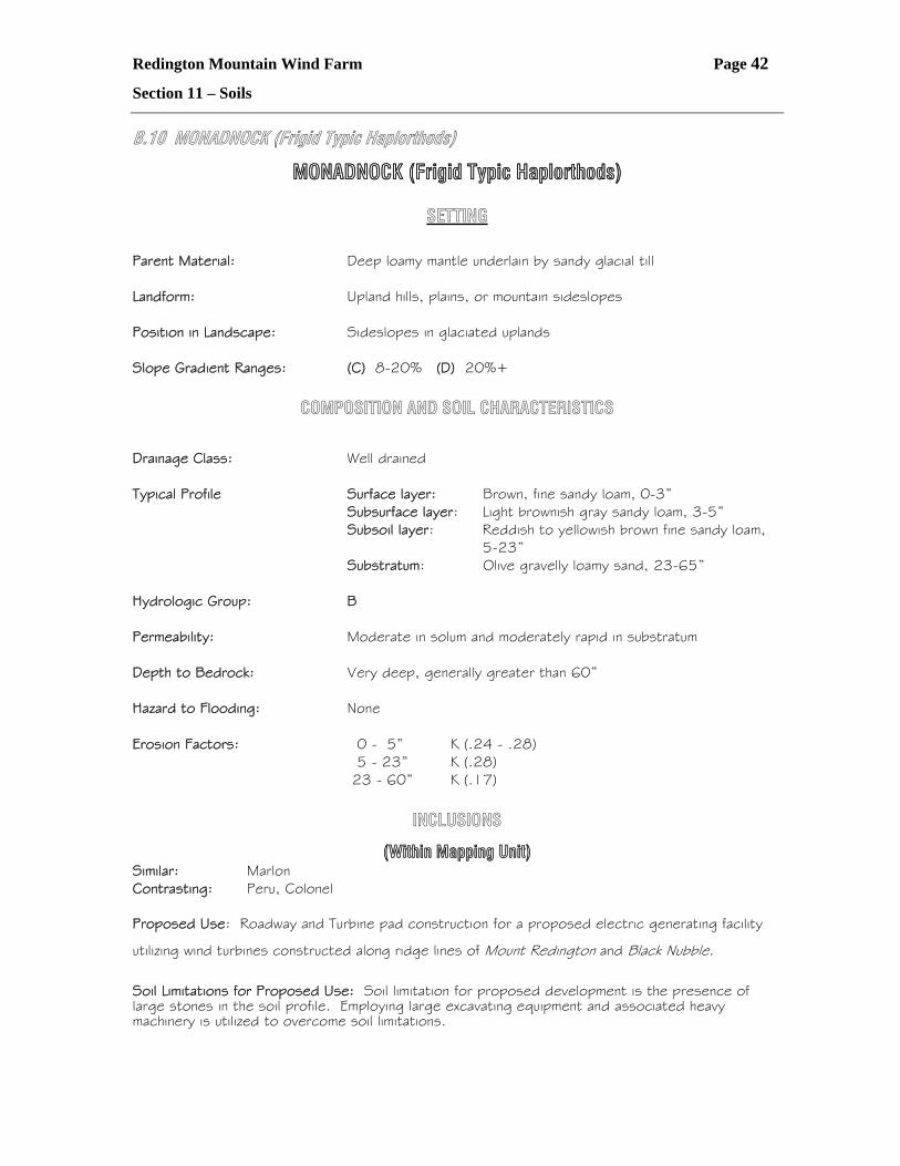
B.10 MONADNOCK (Frigid Typic Haplorthods)
MONADNOCK (Frigid Typic Haplorthods)
SETTING
Parent Material: Deep loamy mantle underlain by sandy glacial till Landform: Upland hills, plains, or mountain sideslopes Position in Landscape: Sideslopes in glaciated uplands Slope Gradient Ranges: (C) 8-20% (D) 20%+
COMPOSITION AND SOIL CHARACTERISTICS
Drainage Class: Well drained Typical Profile Surface layer: Brown, fine sandy loam, 0-3” Subsurface layer: Light brownish gray sandy loam, 3-5” Subsoil layer: Reddish to yellowish brown fine sandy loam,
5-23” Substratum: Olive gravelly loamy sand, 23-65” Hydrologic Group: B Permeability: Moderate in solum and moderately rapid in substratum Depth to Bedrock: Very deep, generally greater than 60” Hazard to Flooding: None Erosion Factors: 0 - 5” K (.24 - .28) 5 - 23” K (.28) 23 - 60” K (.17)
INCLUSIONS
(Within Mapping Unit) Similar: Marlon Contrasting: Peru, Colonel Proposed Use: Roadway and Turbine pad construction for a proposed electric generating facility
utilizing wind turbines constructed along ridge lines of Mount Redington and Black Nubble.
Soil Limitations for Proposed Use: Soil limitation for proposed development is the presence of large stones in the soil profile. Employing large excavating equipment and associated heavy machinery is utilized to overcome soil limitations.
Redington Mountain Wind Farm Page 43
Section 11 – Soils
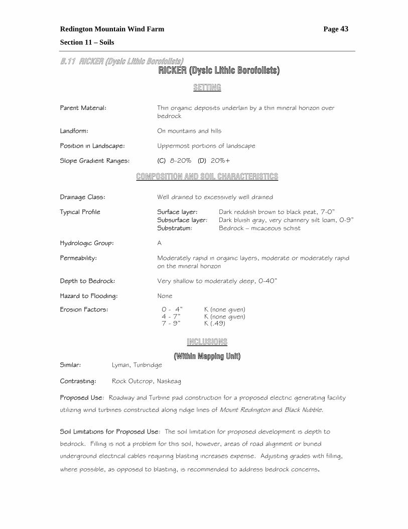
B.11 RICKER (Dysic Lithic Borofolists) RICKER (Dysic Lithic Borofolists)
SETTING
Parent Material: Thin organic deposits underlain by a thin mineral horizon over
bedrock Landform: On mountains and hills Position in Landscape: Uppermost portions of landscape Slope Gradient Ranges: (C) 8-20% (D) 20%+
COMPOSITION AND SOIL CHARACTERISTICS
Drainage Class: Well drained to excessively well drained Typical Profile Surface layer: Dark reddish brown to black peat, 7-0” Subsurface layer: Dark bluish gray, very channery silt loam, 0-9” Substratum: Bedrock – micaceous schist Hydrologic Group: A Permeability: Moderately rapid in organic layers, moderate or moderately rapid
on the mineral horizon Depth to Bedrock: Very shallow to moderately deep, 0-40” Hazard to Flooding: None Erosion Factors: 0 - 4” K (none given) 4 - 7” K (none given) 7 - 9” K (.49)
INCLUSIONS
(Within Mapping Unit) Similar: Lyman, Tunbridge Contrasting: Rock Outcrop, Naskeag Proposed Use: Roadway and Turbine pad construction for a proposed electric generating facility
utilizing wind turbines constructed along ridge lines of Mount Redington and Black Nubble.
Soil Limitations for Proposed Use: The soil limitation for proposed development is depth to
bedrock. Filling is not a problem for this soil, however, areas of road alignment or buried
underground electrical cables requiring blasting increases expense. Adjusting grades with filling,
where possible, as opposed to blasting, is recommended to address bedrock concerns.
Redington Mountain Wind Farm Page 44
Section 11 – Soils
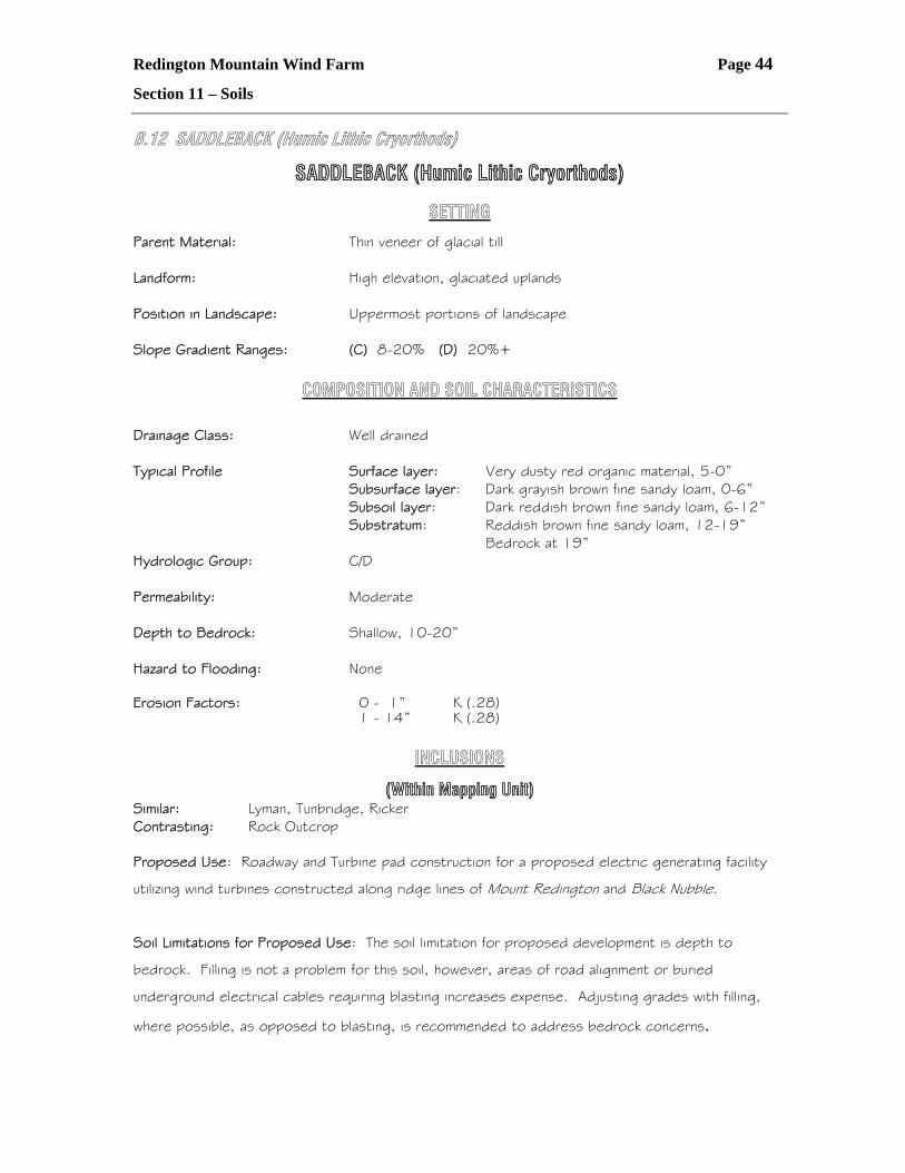
B.12 SADDLEBACK (Humic Lithic Cryorthods)
SADDLEBACK (Humic Lithic Cryorthods)
SETTING
Parent Material: Thin veneer of glacial till Landform: High elevation, glaciated uplands Position in Landscape: Uppermost portions of landscape Slope Gradient Ranges: (C) 8-20% (D) 20%+
COMPOSITION AND SOIL CHARACTERISTICS
Drainage Class: Well drained Typical Profile Surface layer: Very dusty red organic material, 5-0” Subsurface layer: Dark grayish brown fine sandy loam, 0-6” Subsoil layer: Dark reddish brown fine sandy loam, 6-12” Substratum: Reddish brown fine sandy loam, 12-19” Bedrock at 19” Hydrologic Group: C/D Permeability: Moderate Depth to Bedrock: Shallow, 10-20” Hazard to Flooding: None Erosion Factors: 0 - 1” K (.28) 1 - 14” K (.28)
INCLUSIONS
(Within Mapping Unit) Similar: Lyman, Tunbridge, Ricker Contrasting: Rock Outcrop Proposed Use: Roadway and Turbine pad construction for a proposed electric generating facility
utilizing wind turbines constructed along ridge lines of Mount Redington and Black Nubble.
Soil Limitations for Proposed Use: The soil limitation for proposed development is depth to
bedrock. Filling is not a problem for this soil, however, areas of road alignment or buried
underground electrical cables requiring blasting increases expense. Adjusting grades with filling,
where possible, as opposed to blasting, is recommended to address bedrock concerns.
Redington Mountain Wind Farm Page 45
Section 11 – Soils
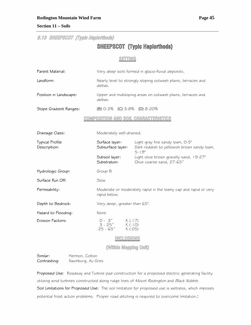
B.13 SHEEPSCOT (Typic Haplorthods)
SHEEPSCOT (Typic Haplorthods)
SETTING Parent Material: Very deep soils formed in glacio-fluvial deposits. Landform: Nearly level to strongly sloping outwash plains, terraces and
deltas. Position in Landscape: Upper and midsloping areas on outwash plains, terraces and
deltas. Slope Gradient Ranges: (B) 0-3% (C) 3-8% (D) 8-20%
COMPOSITION AND SOIL CHARACTERISTICS
Drainage Class: Moderately well-drained. Typical Profile Surface layer: Light gray fine sandy loam, 0-5" Description: Subsurface layer: Dark reddish to yellowish brown sandy loam,
5-19" Subsoil layer: Light olive brown gravelly sand, 19-27" Substratum: Olive coarse sand, 27-65” Hydrologic Group: Group B Surface Run Off: Slow Permeability: Moderate or moderately rapid in the loamy cap and rapid or very
rapid below. Depth to Bedrock: Very deep, greater than 65". Hazard to Flooding: None Erosion Factors: 0 - 3” K (.17) 3 - 25” K (.10) 25 - 65” K (.05)
INCLUSIONS
(Within Mapping Unit)
Similar: Hermon, Colton Contrasting: Naumburg, Au Gres
Proposed Use: Roadway and Turbine pad construction for a proposed electric generating facility
utilizing wind turbines constructed along ridge lines of Mount Redington and Black Nubble.
Soil Limitations for Proposed Use: The soil limitation for proposed use is wetness, which imposes
potential frost action problems. Proper road ditching is required to overcome limitation.:
Redington Mountain Wind Farm Page 46
Section 11 – Soils
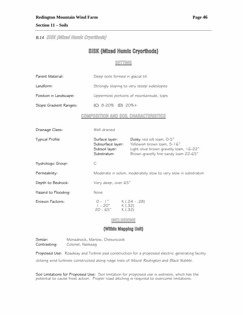
B.14 SISK (Mixed Humic Cryorthods)
SISK (Mixed Humic Cryorthods)
SETTING
Parent Material: Deep soils formed in glacial till Landform: Strongly sloping to very steep sideslopes Position in Landscape: Uppermost portions of mountainside, tops Slope Gradient Ranges: (C) 8-20% (D) 20%+
COMPOSITION AND SOIL CHARACTERISTICS
Drainage Class: Well drained Typical Profile Surface layer: Dusky red silt loam, 0-5” Subsurface layer: Yellowish brown loam, 5-16” Subsoil layer: Light olive brown gravelly loam, 16-22” Substratum: Brown gravelly fine sandy loam 22-65” Hydrologic Group: C Permeability: Moderate in solum, moderately slow to very slow in substratum Depth to Bedrock: Very deep, over 65” Hazard to Flooding: None Erosion Factors: 0 - 1” K (.24 - .28) 1 - 20” K (.32) 20 - 65” K (.32)
INCLUSIONS
(Within Mapping Unit) Similar: Monadnock, Marlow, Chesuncook Contrasting: Colonel, Naskeag Proposed Use: Roadway and Turbine pad construction for a proposed electric generating facility
utilizing wind turbines constructed along ridge lines of Mount Redington and Black Nubble.
Soil Limitations for Proposed Use: Soil limitation for proposed use is wetness, which has the potential to cause frost action. Proper road ditching is required to overcome limitations.
Redington Mountain Wind Farm Page 47
Section 11 – Soils
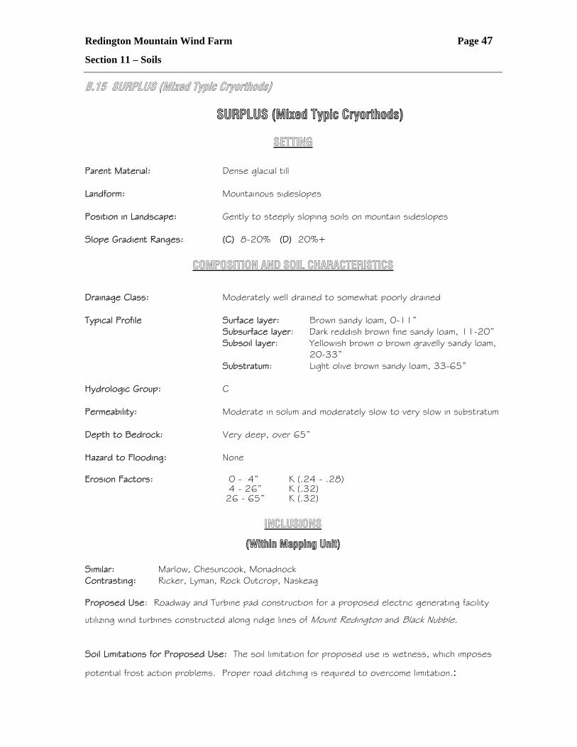
B.15 SURPLUS (Mixed Typic Cryorthods)
SURPLUS (Mixed Typic Cryorthods)
SETTING
Parent Material: Dense glacial till Landform: Mountainous sideslopes Position in Landscape: Gently to steeply sloping soils on mountain sideslopes Slope Gradient Ranges: (C) 8-20% (D) 20%+
COMPOSITION AND SOIL CHARACTERISTICS
Drainage Class: Moderately well drained to somewhat poorly drained Typical Profile Surface layer: Brown sandy loam, 0-11” Subsurface layer: Dark reddish brown fine sandy loam, 11-20” Subsoil layer: Yellowish brown o brown gravelly sandy loam,
20-33” Substratum: Light olive brown sandy loam, 33-65” Hydrologic Group: C Permeability: Moderate in solum and moderately slow to very slow in substratum Depth to Bedrock: Very deep, over 65” Hazard to Flooding: None Erosion Factors: 0 - 4” K (.24 - .28) 4 - 26” K (.32) 26 - 65” K (.32)
INCLUSIONS
(Within Mapping Unit) Similar: Marlow, Chesuncook, Monadnock Contrasting: Ricker, Lyman, Rock Outcrop, Naskeag Proposed Use: Roadway and Turbine pad construction for a proposed electric generating facility
utilizing wind turbines constructed along ridge lines of Mount Redington and Black Nubble.
Soil Limitations for Proposed Use: The soil limitation for proposed use is wetness, which imposes
potential frost action problems. Proper road ditching is required to overcome limitation.:
Redington Mountain Wind Farm Page 48
Section 11 – Soils
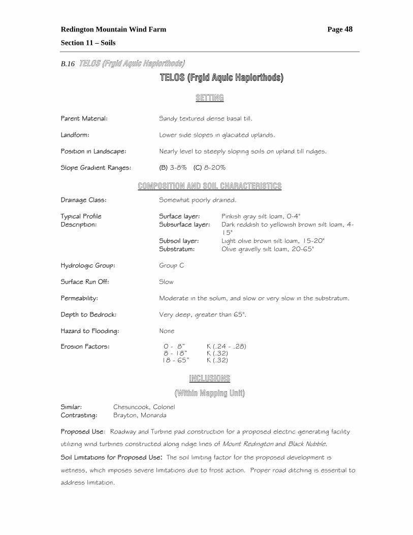
B.16 TELOS (Frgid Aquic Haplorthods)
TELOS (Frgid Aquic Haplorthods)
SETTING Parent Material: Sandy textured dense basal till. Landform: Lower side slopes in glaciated uplands. Position in Landscape: Nearly level to steeply sloping soils on upland till ridges. Slope Gradient Ranges: (B) 3-8% (C) 8-20%
COMPOSITION AND SOIL CHARACTERISTICS
Drainage Class: Somewhat poorly drained. Typical Profile Surface layer: Pinkish gray silt loam, 0-4" Description: Subsurface layer: Dark reddish to yellowish brown silt loam, 4-
15" Subsoil layer: Light olive brown silt loam, 15-20" Substratum: Olive gravelly silt loam, 20-65" Hydrologic Group: Group C Surface Run Off: Slow Permeability: Moderate in the solum, and slow or very slow in the substratum. Depth to Bedrock: Very deep, greater than 65". Hazard to Flooding: None Erosion Factors: 0 - 8” K (.24 - .28) 8 - 18” K (.32) 18 - 65” K (.32)
INCLUSIONS
(Within Mapping Unit)
Similar: Chesuncook, Colonel Contrasting: Brayton, Monarda Proposed Use: Roadway and Turbine pad construction for a proposed electric generating facility
utilizing wind turbines constructed along ridge lines of Mount Redington and Black Nubble.
Soil Limitations for Proposed Use: The soil limiting factor for the proposed development is
wetness, which imposes severe limitations due to frost action. Proper road ditching is essential to
address limitation.
Redington Mountain Wind Farm Page 49
Section 11 – Soils
B.17 TUNBRIDGE (Typic Haplorthods) TUNBRIDGE (Typic Haplorthods)
SETTING Parent Material: Loamy glacial till. Landform: Glaciated uplands. Position in Landscape: Upper positions on landform. Slope Gradient Ranges: (B) 3-8% (C) 8-20% (D) 20+%
COMPOSITION AND SOIL CHARACTERISTICS Drainage Class: Somewhat excessively to well drained, with no evidence of a water
table, or only inches from the bedrock surface during spring and during periods of heavy precipitation.
Typical Profile Surface layer: Black and reddish brown loam and fine sandy Description: loam, 0-4" Subsurface layer: Very dusky red loam, 4-6" Subsoil layer: Dark red loam, 6-10" Substratum layer: Dark brown to brown loam, 10-25". Bedrock
at 25". Hydrologic Group: Group C/D Surface Run Off: Rapid Permeability: Moderate or moderately rapid. Depth to Bedrock: Moderately deep, 20-40". Hazard to Flooding: None Erosion Factors: 0 - 3” K (.20) 3 - 14” K (.20) 14 - 28” K (.20) 28 – 65” K (.20) INCLUSIONS (Within Mapping Unit) Similar: Dixfield, Skerry Contrasting: Lamoine, Lyman Variant, Naskeag, Adams Proposed Use: Roadway and Turbine pad construction for a proposed electric generating facility
utilizing wind turbines constructed along ridge lines of Mount Redington and Black Nubble.
Soil Limitations for Proposed Use: The soil limitation for proposed development is depth to
bedrock. Filling is not a problem for this soil, however, areas of road alignment or buried
underground electrical cables requiring blasting increases expense. Adjusting grades with filling,
where possible, as opposed to blasting, is recommended to address bedrock concerns.

Redington Mountain Wind Farm Page 50
Section 11 – Soils
C
Letters of Correspondence
Redington Mountain Wind Farm Page 51
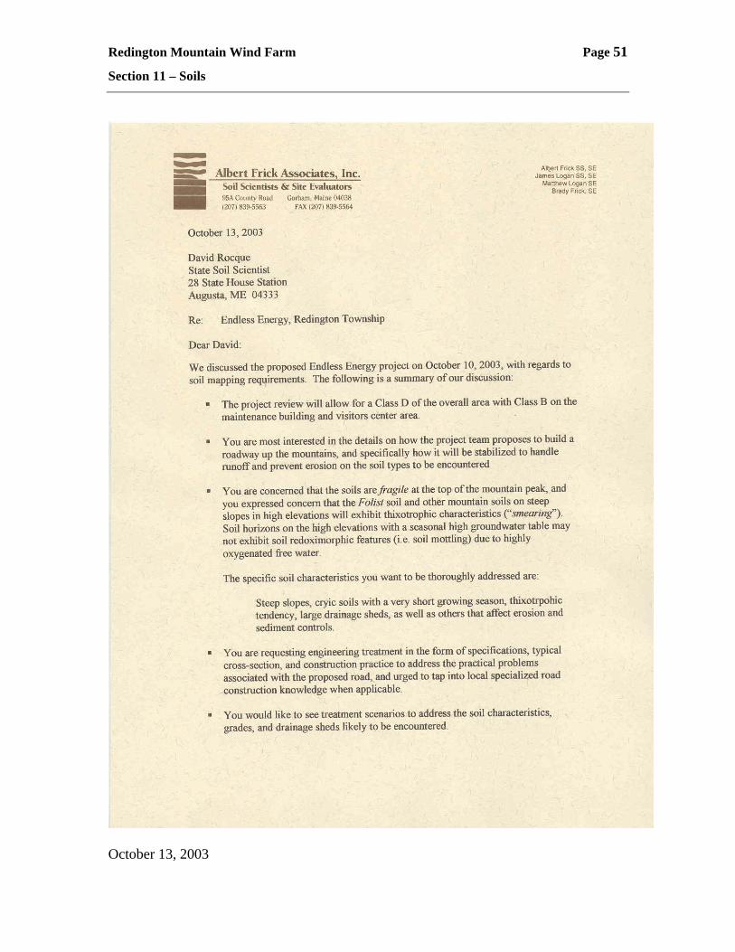
Section 11 – Soils
October 13, 2003
Redington Mountain Wind Farm Page 52
Section 11 – Soils

Redington Mountain Wind Farm Page 53
Section 11 – Soils
D
Additional Photographs
Redington Mountain Wind Farm Page 54
Section 11 – Soils
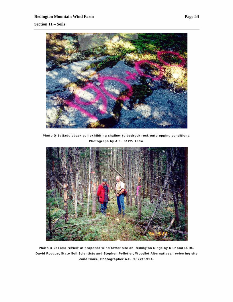
Photo D-1: Saddleback soil exhibiting shallow to bedrock rock outcropping conditions.
Photograph by A.F. 8/22/1994.
Photo D-2: Field review of proposed wind tower site on Redington Ridge by DEP and LURC.
David Rocque, State Soil Scientists and Stephen Pelletier, Woodlot Alternatives, reviewing site
conditions. Photographer A.F. 9/22/1994.
Redington Mountain Wind Farm Page 55
Section 11 – Soils
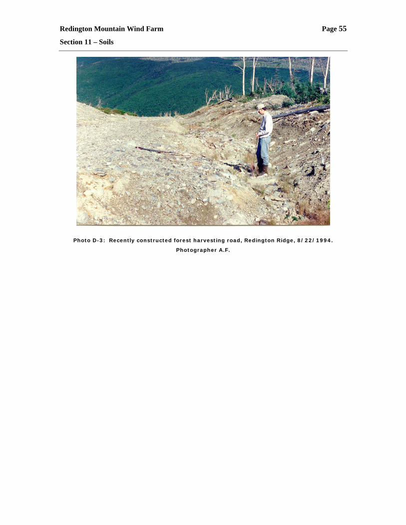
Photo D-3: Recently constructed forest harvesting road, Redington Ridge, 8/22/1994.
Photographer A.F.
Redington Mountain Wind Farm Page 56
Section 11 – Soils
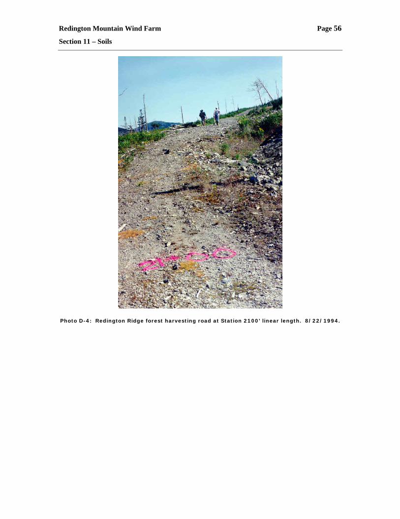
Photo D-4: Redington Ridge forest harvesting road at Station 2100’ linear length. 8/22/1994.