Testing a NATO OPORD Schema with C-BMLnetlab.gmu.edu/pubs/11E-SIW-014.pdf · Testing a NATO OPORD...
7
Testing a NATO OPORD Schema with C-BML Dr. J. Mark Pullen, Mohammad Ababneh, and Samuel Singapogu C4I Center George Mason University Fairfax, VA 22030, USA 703-993-3682 {mpullen, mababneh, ssingapo}@c4i.gmu.edu Richard Brown Billy Murphy & Associates Battle Command Battle Lab, U.S. Army Combined Arms Center Pope Hall, Bldg 470, 806 Harrison Ave Ft Leavenworth, KS 66027 913-684-7684 [email protected] Keywords: Command and Control, Simulation, BML, C-BML, NATO, Operations Order NATO MSG-085 was chartered to "Investigate approaches for the deployment of Coalition BML capabilities complementing existing operational C2 system exchange mechanisms." A recognized capability needed to achieve this is a functional NATO Operations Order (OPORD) for the Battle Management Language (BML). GMU has developed a schema for a NATO OPORD, based on our earlier work with an Army OPORD for Integrated BML (IBML) and, before that, the GeoBML OPORD that has been used in the Common Ground Joint Capability Technology Demonstration. The GMU NATO OPORD schema is available to MSG-085 as a basis for further development. This paper describes the resulting NATO OPORD schema and the associated script for the Scripted BML Web Server, including a description of the modifications necessary to conform to the new SISO C-BML Phase 1 Trial Use draft schema. It concludes with an extended design rationale and implementation details of the example order developed for testing, including consideration of the anticipated application by MSG-085. 1. Introduction This paper describes a developmental NATO OPORD schema for the Battle Management Language (BML). Parts of this paper appeared previously in [14] and are updated here. BML and its various proposed extensions are intended to facilitate interoperation among command and control (C2) and modeling and simulation (M&S) systems by providing a common, agreed-to format for the exchange of information such as orders and reports [1]. In recent implementation, this has been accomplished by providing a repository service that the participating systems can use to post and retrieve messages expressed in BML. The service is implemented as middleware, essential to the operation of BML, and can be either centralized or distributed. Recent implementations have focused on use of the Extensible Markup Language (XML) along with Web service (WS) technology, a choice that is consistent with the Network Centric Operations strategy currently being adopted by the US Department of Defense and its coalition allies [2]. Coalition operations have a need for interoperability that is even greater than that of national Service and Joint operations. Because coalitions must function under greater complexity due to significant differences among doctrine and human language barriers, the agility to train and rehearse rapidly before the actual operation is highly important [3]. The NATO RTO Modeling and Simulation Group (MSG) recognized this need and chartered Technical Activity MSG-048 to explore the promise of BML in coalitions combined with SOA technologies. Earlier major demonstrations by MSG-048 are described in [3]. That paper also describes the final major activity of MSG-048, involving experimentation, performed by a team from ten nations. The experimental configuration used is shown in Figure 1 and included six national C2 systems and 5 national simulation systems, supported by the scripted BML server developed by the GMU C4I Center.
Transcript of Testing a NATO OPORD Schema with C-BMLnetlab.gmu.edu/pubs/11E-SIW-014.pdf · Testing a NATO OPORD...
Testing a NATO OPORD Schema with C-BML
Dr. J. Mark Pullen, Mohammad Ababneh, and Samuel Singapogu
C4I Center George Mason University Fairfax, VA 22030, USA
703-993-3682 {mpullen, mababneh, ssingapo}@c4i.gmu.edu
Richard Brown
Billy Murphy & Associates Battle Command Battle Lab, U.S. Army Combined Arms Center
Pope Hall, Bldg 470, 806 Harrison Ave Ft Leavenworth, KS 66027
913-684-7684 [email protected]
Keywords: Command and Control, Simulation, BML, C-BML, NATO, Operations Order
NATO MSG-085 was chartered to "Investigate approaches for the deployment of Coalition BML capabilities complementing existing operational C2 system exchange mechanisms." A recognized capability needed to achieve this is a functional NATO Operations Order (OPORD) for the Battle Management Language (BML). GMU has developed a schema for a NATO OPORD, based on our earlier work with an Army OPORD for Integrated BML (IBML) and, before that, the GeoBML OPORD that has been used in the Common Ground Joint Capability Technology Demonstration. The GMU NATO OPORD schema is available to MSG-085 as a basis for further development. This paper describes the resulting NATO OPORD schema and the associated script for the Scripted BML Web Server, including a description of the modifications necessary to conform to the new SISO C-BML Phase 1 Trial Use draft schema. It concludes with an extended design rationale and implementation details of the example order developed for testing, including consideration of the anticipated application by MSG-085. 1. Introduction This paper describes a developmental NATO OPORD schema for the Battle Management Language (BML). Parts of this paper appeared previously in [14] and are updated here.
BML and its various proposed extensions are intended to facilitate interoperation among command and control (C2) and modeling and simulation (M&S) systems by providing a common, agreed-to format for the exchange of information such as orders and reports [1]. In recent implementation, this has been accomplished by providing a repository service that the participating systems can use to post and retrieve messages expressed in BML. The service is implemented as middleware, essential to the operation of BML, and can be either centralized or distributed. Recent implementations have focused on use of the Extensible Markup Language (XML) along with Web service (WS) technology, a choice that is consistent with the Network Centric Operations strategy currently
being adopted by the US Department of Defense and its coalition allies [2].
Coalition operations have a need for interoperability that is even greater than that of national Service and Joint operations. Because coalitions must function under greater complexity due to significant differences among doctrine and human language barriers, the agility to train and rehearse rapidly before the actual operation is highly important [3]. The NATO RTO Modeling and Simulation Group (MSG) recognized this need and chartered Technical Activity MSG-048 to explore the promise of BML in coalitions combined with SOA technologies. Earlier major demonstrations by MSG-048 are described in [3]. That paper also describes the final major activity of MSG-048, involving experimentation, performed by a team from ten nations. The experimental configuration used is shown in Figure 1 and included six national C2 systems and 5 national simulation systems, supported by the scripted BML server developed by the GMU C4I Center.
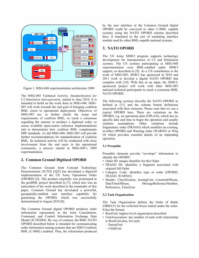
Figure 1. MSG-048 experimentation architecture 2009 The MSG-085 Technical Activity, Standardization for C2-Simulation Interoperation, started in June 2010. It is intended to build on the work done in MSG-048. MSG-085 will work towards the end goal of bringing coalition BML closer to operational deployment. Objectives of MSG-085 are: to further clarify the scope and requirements of coalition BML; to reach a consensus regarding the manner to produce a digitized order; to assess available open-source reference implementations and to demonstrate how coalition BML complements MIP standards. As did MSG-048, MSG-085 will provide further recommendations for standardization of coalition BML. Its technical activity will be conducted with close involvement from the end users in the operational community, a process started in MSG-048’s 2009 experimentation. 2. Common Ground Digitized OPORD The Common Ground Joint Concept Technology Demonstration (JCTD) [4][5] has developed a digitized implementation of the US Army Operations Order (OPORD) [6]. This product originally was prototyped in the geoBML project described in [7], which also was an antecedent of the work described in the remainder of this paper. Common Ground has developed a powerful, geospatially-enabled user interface capability for generating the OPORD, which was successfully demonstrated in August 2010 [8]. The Common Ground digital OPORD produces order information represented in the Joint Consultation, Command, and Control Information Exchange Data Model (JC3IEDM). By way of contrast, the BML NATO OPORD described below is intended for communicating order information among systems that are SISO Coalition BML (C-BML) enabled. Thus, the information produced
by the user interface in the Common Ground digital OPORD could be conveyed to other C-BML capable systems using the NATO OPORD schema described here, if translated in the sort of mediating interface module used by other BML-capable national systems. 3. NATO OPORD The US Army SIMCI program supports technology development for interoperation of C2 and Simulation systems. The US systems participating in MSG-048 experimentation were BML-enabled under SIMCI support, as described in [9]. As a US contribution to the work of MSG-085, SIMCI has sponsored in 2010 and 2011 work to develop a digital NATO OPORD that complies with [10]. With this as an input, the SIMCI-sponsored project will work with other MSG-085 national technical participants to reach a consensus BML NATO OPORD. The following sections describe the NATO OPORD as defined in [11] and the schema format definitions associated with their elements. Please note that we use a typical OPORD here. There are variations on the OPORD, e.g. an operations plan (OPLAN), which has no specific date and time to begin the operation and usually contains assumptions. Other variations include fragmentary order (FRAGO) which modifies an existing, in-effect OPORD and Warning order (WARNO or Wng O) which provides essential details of an impending operation. 3.1 Preamble Preamble elements provide “envelope” information to identify the OPORD: • Order ID: unique identifier for this Order • FRAGO ID: identifies a fragment associated with
original full Order • Category Code: identifies type or order (OPORD,
FRAGO, WARNO) • Header: Classification, IssuingUnit, LocationOfIssue,
DateTimeOfIssue, MessageReferenceNumber, References, TimeZone
3.2 Task Organization The Task Organization defines the Order of Battle (ORBAT) for the collected forces tasked under the order. It has the format: • RootUnit: highest level organization described • UnitAssociation: any number of units with relationship
to RootUnit plus, for each: – ParentUnit – ChildUnit
– Relationship e.g. supporting, assigned to, direct support, attached, etc.
3.3 Situation Section This is the first of the “five paragraphs” that are well known to military officers. It provides background information necessary to interpret the sections that follow. The “situation” provides the setting for the operation and generally describes what is known of the enemy forces, including partisans and the civilian population, geospatial factors, weather, and ephemeris data, and the disposition of friendly forces. Formats we have used in our BML NATO OPORD schema are included below, in italics). • Weather (MeteorologicFeature; optional) • EnemyForces
– EnemyOrderOfBattle (TaskOrganization format; optional)
– MostProbableCourseOfAction (Task format; optional)
– MostDangerousCourseOfAction (Task format; optional)
• FriendlyForces – TwoLevelsUp, OneLevelUp, LeftFlankUnit,
RightFlankUnit, ForwardUnit, RearUnit, DeepUnit, ReserveUnit (Mission format; all optional)
• AttachmentsAndDetachments (TaskOrganization format; optional)
• Assumptions (free text; optional; properly used only in Plan not Order)
• CommandersEvaluation (free text; optional) 3.4 Mission Section This section states the mission the tasker has received from a higher echelon. It consists of” • The Task(s) to be performed (Task format) • Description of the mission (free text) 3.5 Execution Section This section provides the tasker’s description of the operational concept of fires and maneuver of the combat elements under the tasker. • CommandersIntent (free text) “…a concise expression of the purpose of the operation which describes the desired end state.” [10]. In US doctrine, this statement succinctly describes what constitutes success for the operation. • ConceptOfOperations (free text) • DescriptionOfMission (free text) • ExecutionPhases (any number); for each. This
describes the scheme of maneuver and supporting fires: –PhaseName (unique identifier) –StartTime (absolute or relative)
–What (as in Task) • A list of Tasks; for each subordinate maneuver unit.
(A second paragraph describes tasks to combat support units.) Both take the following format: – TaskeeWho: who will perform the task – What: what they are tasked to do – StartWhen: when they will begin (can be relative to
other tasks or their results) – EndWhen: when then must finish (optional) – Where: where they will do it (can be relative to
other BML objects) – Affected: who or what object is affected (optional) – Why: effect to be achieved and/or Task supported
(optional) 3.6 Administration and Logistics Section This section provides direction to the service support elements of the force. In its present form, it is largely free text. However, as BML expands to communicate unambiguous direction to those elements (or their simulations) it should be possible to render this information to a level of digital precision comparable to that of the Mission Section. For example, a request for helicopter medical evacuation is a highly standardized format that lends itself to BML: • SupportConcept (free text) • MaterielAndServices (free text) • Personnel (free text) • MedicalEvacuationAndHospitalization (free text) • CivilMilitaryCooperation (free text) • Miscellaneous (free text) 3.7 Command and Signal Section This section provides direction for communications processes associated with order execution. Its present form also is free text. However, simulations of supporting communications already exist with a level of specificity such that BML could be expanded to a precise, unambiguous definition of: • CommandControlAndCommunications (free text) • Command (free text) 3.8 Overlay Section This section provides operational graphics that traditionally took the form of map overlays depicting the concept of operations and control measures for implementation. The Common Ground program described in section 2 above has advanced this information to the realm of digital geospatial information. The traditional format was, for each overlay: • OverlayName: unique identifier for overlay • ControlFeature reference (unlimited number) • Time: effective date-time • Unit ID: unit to which overlay applies
3.9 Appendices Traditional operations orders contain a large amount of coordinating information in the form of annexes for various functions. The overall document for a large organization can be voluminous. Our approach to the NATO OPORD has been to include any critical information from these annexes in the body of the BML OPORD. This may require reconsideration as MSG-085 broadens the operational scope of BML. 4. Changes in scripting to migrate from
IBML to C-BML Light schema The SISO C-BML Product Development Group has released a Phase 1 Draft Schema for Trial Use. We have implemented that schema in our open source Scripted BML server [12]. This section describes the changes we made in moving from the IBML schema used by MSG-048 to the C-BML Light schema. • TaskPush: In IBML, Tasks could be of type Air Task
or Ground Task. And so, the script had two BusinessObjectTransactions (BOTs) one for each type of Task. In C-BML, there is only one type of task and so there is only one BOT for a TaskPush.
• WhatWhenPush: In IBML, When was of type AbsoluteWhen or RelativeWhen. In C-BML AbsoluteWhen can be of type Specified or Unspecified. Unspecified time does not have a associated time but only has a qualifier code. The new script looks to see whether time is of type specified of unspecified. The table that gets updated isActionTask. RelativeWhen: In IBML, the table used to store RelativeTime is ActionTask while in C-BML; each relative time is stored in a new entry of Action Temporal Association.
• WhyPush: In IBML, ‘why’ is stored in ActionEffect, while in C-BML, the mappings required ActionEffectItem to be updated as well.
• AtWherePush: In IBML, AtWhere had WhereClass, WhereCategory to provide “meta” information about the AtWhere. C-BML does not have that information since its implied in the structure of the AtWhere. The new script ignores the columns in ObjectItem and ObjectType that used to store WhereClass and WhereCategory. C-BML has two types of Where (for Both AtWhere and RouteWhere), one specific and one derived. The SpecificWhere has all the information to create the Where, while a derived ‘Where’ is a reference to another Where previously created. If the input has a derived ‘Where’, the script looks for the Where in the database and returns the ObjectID of the previously created Where. In addition, each Location point in C-BML can be a specific point or a pointer to a previously created
Location point. In addition to Points, Lines and Surfaces, C-BML has an additional type called Polygon Area. Polygon Area requires update to the table Polygon Area that is a subclass of Surface.
• In C-BML, points can have a displacement to create a relative point. Displacement is created using a Relative Coordinate System. Additional tables that need to be updated are Point-Reference and Relative-Point.
• RouteWherePush: A RouteWhere is a set of points in IBML, whereas a C-BML Route is a set of AtWhere. This means that the C-BML script creates an AtWhere for every element in the RouteWhere. In addition, each element is connected to each other and the first element of the Route using Object-Item-Association. Each “VIA” point is connected to another “VIA” point using Object-Item-Association with a cat_code “ISPART” and each “VIA” point is connected to the “from” point using Object-Item-Association with cat_code “ISSCSR”.
• Reporting-Data Time: In IBML, ReportingTime can only be AbosluteTime which is updated in Reporting-Data (the only table to be updated for Report Header in IBML). In C-BML, ReportingTime can be absolute or relative. If the time is absolute, Reporting-Data-Absolute-Timing is updated whereas, if the time was relative, Reporting-Data-Relative timing is updated. Both, entities are sub classes of Reporting-Data.
5. NATO OPORD Example Implementation In order to test the newly developed C-BML based schema, we have built a test environment that consists of the following components: • Definition of an XML schema for each section defined
above, • A server that can push and pull XML OPORD
documents, and • An example/test scenario. These test environment components are are available as open source through GMU C4I Center BML website. (http://c4i.gmu.edu/BML). 5.1 Schema As in the previous section, the GMU CBML-Light OPORD schema is a logical successor to the Integrated BML (IBML) schema used by MSG-048 [3]. It contains XML elements for every category of information show in section 3 above.
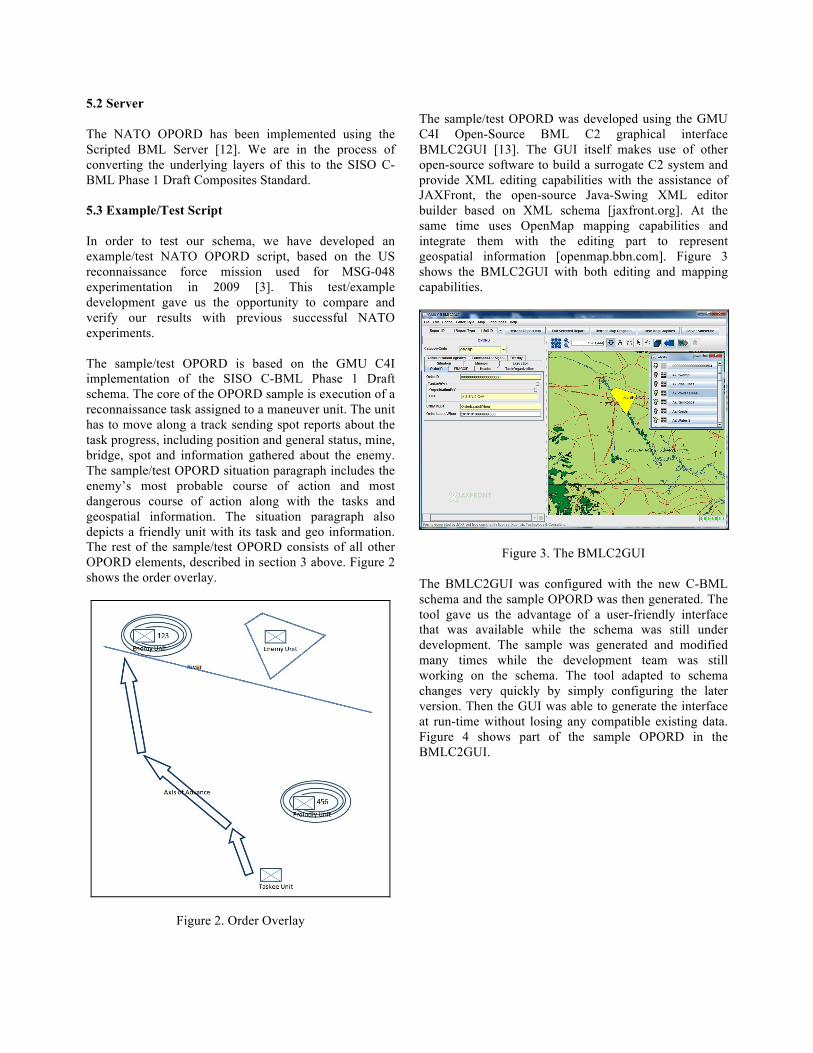
5.2 Server The NATO OPORD has been implemented using the Scripted BML Server [12]. We are in the process of converting the underlying layers of this to the SISO C-BML Phase 1 Draft Composites Standard. 5.3 Example/Test Script In order to test our schema, we have developed an example/test NATO OPORD script, based on the US reconnaissance force mission used for MSG-048 experimentation in 2009 [3]. This test/example development gave us the opportunity to compare and verify our results with previous successful NATO experiments. The sample/test OPORD is based on the GMU C4I implementation of the SISO C-BML Phase 1 Draft schema. The core of the OPORD sample is execution of a reconnaissance task assigned to a maneuver unit. The unit has to move along a track sending spot reports about the task progress, including position and general status, mine, bridge, spot and information gathered about the enemy. The sample/test OPORD situation paragraph includes the enemy’s most probable course of action and most dangerous course of action along with the tasks and geospatial information. The situation paragraph also depicts a friendly unit with its task and geo information. The rest of the sample/test OPORD consists of all other OPORD elements, described in section 3 above. Figure 2 shows the order overlay.
Figure 2. Order Overlay
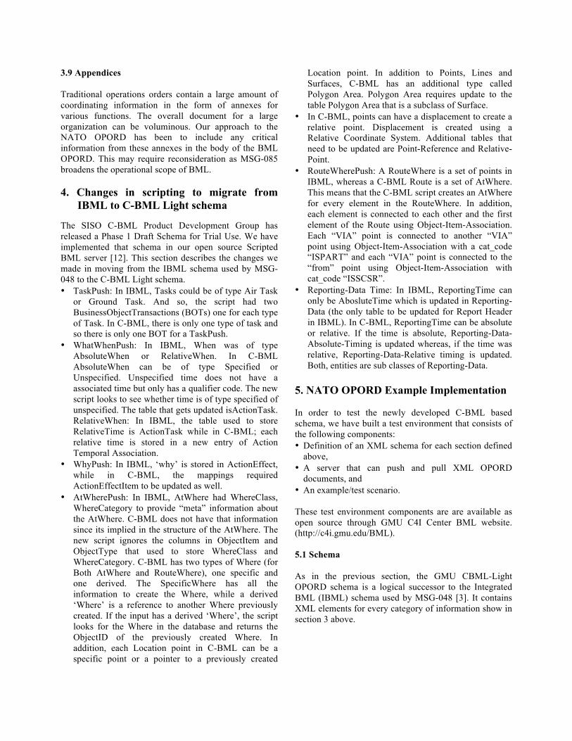
The sample/test OPORD was developed using the GMU C4I Open-Source BML C2 graphical interface BMLC2GUI [13]. The GUI itself makes use of other open-source software to build a surrogate C2 system and provide XML editing capabilities with the assistance of JAXFront, the open-source Java-Swing XML editor builder based on XML schema [jaxfront.org]. At the same time uses OpenMap mapping capabilities and integrate them with the editing part to represent geospatial information [openmap.bbn.com]. Figure 3 shows the BMLC2GUI with both editing and mapping capabilities.
Figure 3. The BMLC2GUI
The BMLC2GUI was configured with the new C-BML schema and the sample OPORD was then generated. The tool gave us the advantage of a user-friendly interface that was available while the schema was still under development. The sample was generated and modified many times while the development team was still working on the schema. The tool adapted to schema changes very quickly by simply configuring the later version. Then the GUI was able to generate the interface at run-time without losing any compatible existing data. Figure 4 shows part of the sample OPORD in the BMLC2GUI.
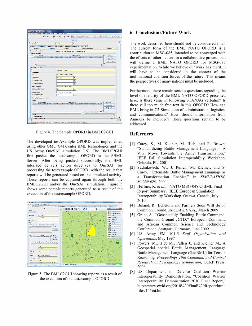
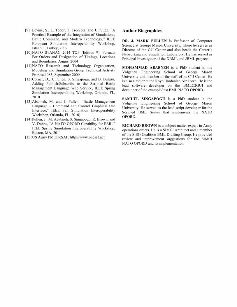
Figure 4. The Sample OPORD in BMLC2GUI The developed test/example OPORD was implemented using other GMU C4I Center BML technologies and the US Army OneSAF simulation [15]. The BMLC2GUI first pushes the test/example OPORD to the SBML Server. After being pushed successfully, the BML interface delivers action directives to OneSAF for processing the test/example OPORD, with the result that reports will be generated based on the simulated activity. These reports can be captured again through both the BMLC2GUI and/or the OneSAF simulation. Figure 5 shows some sample reports generated as a result of the execution of the test/example OPORD.
Figure 5. The BMLC2GUI showing reports as a result of the execution of the test/example OPORD
6. Conclusions/Future Work
The work described here should not be considered final. The current form of the BML NATO OPORD is a contribution to MSG-085, intended to be converged with the efforts of other nations in a collaborative process that will define a BML NATO OPORD for MSG-085 experimentation. While we believe our work has merit, it will have to be considered in the context of the multinational coalition forces of the future. This means the perspectives of many nations must be included. Furthermore, there remain serious questions regarding the level of maturity of the BML NATO OPORD presented here. Is there value in following STANAG verbatim? Is there still too much free text in this OPORD? How can BML bring in C2-Simulation of administration, logistics, and communications? How should information from Annexes be included? These questions remain to be addressed. References [1] Carey, S., M. Kleiner, M. Hieb, and R. Brown,
“Standardizing Battle Management Language – A Vital Move Towards the Army Transformation,” IEEE Fall Simulation Interoperability Workshop, Orlando, FL, 2001
[2] Sudnikovich, W., J. Pullen, M. Kleiner, and S. Carey, “Extensible Battle Management Language as a Transformation Enabler,” in SIMULATION, 80:669-680, 2004
[3] Heffner, K. et al., “NATO MSG-048 C-BML Final Report Summary,” IEEE European Simulation Interoperability Workshop, Ottawa, Canada, July 2010
[4] Boland, R., Echelons and Partners Soon Will Be on Common Ground, AFCEA SIGNAL, March 2009
[5] Grant, S., “Geospatially Enabling Battle Command: the Common Ground JCTD,” European Command and African Common Science and Technology Conference, Stuttgart, Germany, June 2009
[6] US Army FM 101-5 Staff Organization and Operations, May 1997
[7] Powers, M., Hieb M., Pullen J., and Kleiner M., A Geospatial spatial Battle Management Language Battle Management Language (GeoBML) for Terrain Reasoning. Proceedings 10th Command and Control Research and technology Symposium, CCRP Press, 2006
[8] US Department of Defense Coalition Warrior Interoperability Demonstration, “Coalition Warrior Interoperability Demonstration 2010 Final Report,” http://www.cwid.org/2010%20Final%20Report/htmlfiles/145int.html
[9] Levine, S., L. Topor, T. Troccola, and J. Pullen, “A Practical Example of the Integration of Simulations, Battle Command, and Modern Technology,” IEEE European Simulation Interoperability Workshop, Istanbul, Turkey, 2009
[10] NATO STANAG 2014 TOP (Edition 9), Formats For Orders and Designation of Timings, Locations and Boundaries, August 2004
[11] NATO Research and Technology Organization, Modeling and Simulation Group Technical Activity Proposal 085, September 2009
[12] Corner, D., J. Pullen, S. Singapogu, and B. Bulusu, Adding Publish/Subscribe to the Scripted Battle Management Language Web Service, IEEE Spring Simulation Interoperability Workshop, Orlando, FL, 2010
[13] Ababneh, M. and J. Pullen, “Battle Management Language – Command and Control Graphical Use Interface,” IEEE Fall Simulation Interoperability Workshop, Orlando, FL, 2010)
[14] Pullen, J., M. Ababneh, S. Singapogu, R. Brown, and V. Dobbs, “A NATO OPORD Capability for BML,” IEEE Spring Simulation Interoperability Workshop, Boston, MA, 2011
[15] US Army PM OneSAF, http://www.onesaf.net
Author Biographies DR. J. MARK PULLEN is Professor of Computer Science at George Mason University, where he serves as Director of the C4I Center and also heads the Center’s Networking and Simulation Laboratory. He has served as Principal Investigator of the XBML and JBML projects. MOHAMMAD ABABNEH is a PhD student in the Volgenau Engineering School of George Mason University and member of the staff of its C4I Center. He is also a major at the Royal Jordanian Air Force. He is the lead software developer on the BMLC2GUI and developer of the example/test BML NATO OPORD. SAMUEL SINGAPOGU is a PhD student in the Volgenau Engineering School of George Mason University. He served as the lead script developer for the Scripted BML Server that implements the NATO OPORD. RICHARD BROWN is a subject matter expert in Army operations orders. He is a SIMCI Architect and a member of the SISO Coalition BML Drafting Group. He provided review and improvement suggestions for the SIMCI NATO OPORD and its implementation.