STEAM POWER PLANT 2.1 Unit 2 - PVT STEAM POWER PLANT 2.5 Figure 2.4: Bucket elevator. 4. Grab bucket...
50
2.1 INTRODUCTION Description The fuel used in a steam power plant is coal. Coal contains elements which get oxidised during reaction with oxygen, supplied by air in the furnace of the steam generator, with the release of a large amount of energy. The large amount of energy released during the reaction is transferred to water which is converted to high pressure steam. This high pressure steam is made to undergo expansion to low pressure in a turbine, thereby effecting a conversion of low grade heat energy into high grade mechanical work which is manifested as ‘Torque’ at the turbine shaft. This torque is transferred directly to the rotor of the electrical generator. Electrical energy is thus produced. The potential of the electrical energy is then raised by transformers. 2.2 FUEL HANDLING SYSTEM Coal delivery equipment is one of the major components of plant cost. The various steps involved in coal handling are as follows: 1. Coal delivery. 2. Unloading. 3. Preparation. 4. Transfer. 5. Outdoor storage. 6. Covered storage. 7. Inplant handling. 8. Weighing and measuring. 9. Feeding the coal into furnace. Unit 2 Steam Power Plant
Transcript of STEAM POWER PLANT 2.1 Unit 2 - PVT STEAM POWER PLANT 2.5 Figure 2.4: Bucket elevator. 4. Grab bucket...

STEAM POWER PLANT 2.1
2.1 INTRODUCTIONDescription
The fuel used in a steam power plant is coal. Coal contains elements which getoxidised during reaction with oxygen, supplied by air in the furnace of the steam generator,with the release of a large amount of energy. The large amount of energy released duringthe reaction is transferred to water which is converted to high pressure steam. This highpressure steam is made to undergo expansion to low pressure in a turbine, thereby effectinga conversion of low grade heat energy into high grade mechanical work which is manifestedas ‘Torque’ at the turbine shaft.
This torque is transferred directly to the rotor of the electrical generator. Electricalenergy is thus produced. The potential of the electrical energy is then raised by transformers.
2.2 FUEL HANDLING SYSTEMCoal delivery equipment is one of the major components of plant cost. The various
steps involved in coal handling are as follows:
1. Coal delivery. 2. Unloading.
3. Preparation. 4. Transfer.
5. Outdoor storage. 6. Covered storage.
7. Inplant handling. 8. Weighing and measuring.
9. Feeding the coal into furnace.
Unit 2
Steam Power Plant
STEAM POWER PLANT 2.5
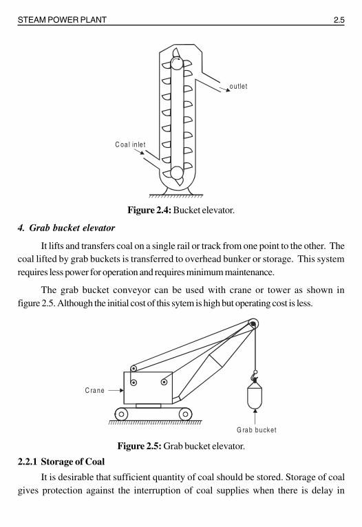
Figure 2.4: Bucket elevator.
4. Grab bucket elevator
It lifts and transfers coal on a single rail or track from one point to the other. Thecoal lifted by grab buckets is transferred to overhead bunker or storage. This systemrequires less power for operation and requires minimum maintenance.
The grab bucket conveyor can be used with crane or tower as shown infigure 2.5. Although the initial cost of this sytem is high but operating cost is less.
Figure 2.5: Grab bucket elevator.
2.2.1 Storage of Coal
It is desirable that sufficient quantity of coal should be stored. Storage of coalgives protection against the interruption of coal supplies when there is delay in
C oa l in le t
o utle t
C ra ne
G ra b bu cket

2.8 POWER PLANT ENGINEERING
The coal received by the plant from the mine may vary widely in sizes. It is necessaryto make the coal of uniform size before passing the pulveriser for efficient grinding. Thecoal received from the mine is passed through a preliminary crusher to reduce the size toallowable limit (30 mm). The crushed coal is further passed over magnetic separatorwhich removes pyrites and tramp iron. The further equipment through which coal ispassed before passing to pulveriser are already shown in figure 2.7.
2.3 PULVERISING MILLS
2.3.1 Ball Mill
A line diagram of ball mill using two classifiers is shown in figure 2.8. It consists ofa slowly rotating drum which is partly filled with steel balls. Raw coal from feeders issupplied to the classifiers from where it moves to the drum by means of a screw conveyor.As the drum rotates the coal gets pulverised due to the combined impact between coal andsteel balls. Hot air is introduced into the drum. The powdered coal is picked up by the airand the coal air mixture enters the classifiers, where sharp changes in the direction of themixture throw out the oversized coal particles. The over-sized particles are returned to thedrum. The coal air mixture from the classifier moves to the exhauster fan and then it issupplied to the burners.
Figure 2.8: Ball mill.
Classifiers
Hot air
Exhauster fan
To burnerFeeders
Drum

STEAM POWER PLANT 2.9
2.3.2 Ball and Race Mills
Figure 2.9 shows a ball and race mill.
Figure 2.9: Ball and race mill.
In this mill the coal passes between the rotating elements again and again until it hasbeen pulverised to desired degree of fineness. The coal is crushed between two movingsurfaces, namely, balls and races. The upper stationary race and lower rotating race drivenby a worm and gear hold the balls between them. The raw coal supplied falls on the innerside of the races. The moving balls and races catch coal between them to crush it to apowder. The necessary force needed for crushing is applied with the help of springs. The
Lowerrace
Hot prim aryair supply
W orm
Rotatingclassifier
Upperrace
Spring
Pulverised coalto burners
Rawcoal feed
GearHot prim aryair supply
Ball
Grindingelements

2.10 POWER PLANT ENGINEERING
hot air supplied picks up the coal dust as it flows between the balls and races, and thenenters the classifier. Where oversized coal particles are returned for further grinding, where-as the coal particles of required size are discharged from the top of classifier.
Advantages
i) Lower capital cost. ii) Lower power consumption.
iii) Less space required. iv) Less weight.
2.4 PULVERISED COAL FIRING SYSTEMPulverised coal firing is done by two systems:
i) Unit system or Direct system. ii) Bin or Central system.
2.4.1 Unit System
In this system (figure 2.10) the raw coal from the coal bunker drops on to thefeeder.
Figure 2.10: Unit system.
Hot air is passed through coal in the feeder to dry the coal. The coal is then transferredto the pulverising mill where it is pulverised. Primary air is supplied to the mill, by the fan.The mixture of pulverised coal and primary air then flows to burner where secondary air isadded. The unit system is so called from the fact that each burner or a burner group andpulveriser constitute a unit.
Advantages
1. The system is simple and cheaper than the central system.
2. There is direct control of combustion from the pulverising mill.
3. Coal transportation system is simple.
S e con d a ry a ir
P r im a ry a irco al
B u rn e rR a w co a l
b u n ke r
F e e de r
H o t a ir
F u rn a ce
P u lve ris in gm ill
F a n

STEAM POWER PLANT 2.13
Lum
p co
al (
Sto
kers
)
Cru
shed
fine
ly
size
d co
alO
ver
feed
Und
er fe
ed
Hig
h tu
rbul
ence
fu
rnac
e (c
yclo
ne)
Pul
veris
edco
alC
onve
yor
stok
erH
oriz
onta
l re
tort
S
lopp
ing
reto
rt
Mec
hani
cal
thro
wJe
t thr
owC
hain
gra
te
Sin
gle
Twin
Ram
feed
Scr
ew fe
ed
Gra
tes
stat
iona
ryG
rate
s ag
itate
d
Ove
r th
row
Und
er th
row
Dum
p gr
ate
Tra
velli
nggr
ate
Air
jet
Ste
am je
t
Nat
ural
draf
t
For
ced
draf
t
Mul
tiple
re
tort
Sho
rtfla
me
Long
flam
eTa
ngen
tial
flam
e
Spr
eade
rst
oker
Spr
eade
rst
oker
Cla
ssifi
catio
n of
com
bust
ion
syst
em
The
det
aile
d cl
assi
fica
tion
of c
ombu
stio
n sy
stem
s use
d fo
r coa
l bur
ning
is g
iven
bel
ow
2.14 POWER PLANT ENGINEERING
The hand firing system is the simplest method of fuel firing but it cannot be used inmodern power plants as it gives lower combustion efficiency, it does not respond quicklyto fluctuation loads and the control of draught is difficult.
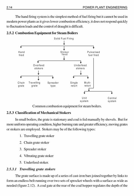
2.5.2 Combustion Equipment for Steam Boilers
Common combustion equipment for steam boilers.
2.5.3 Classification of Mechanical Stokers
In small boilers, the grate is stationary and coal is fed manually by shovels. But formore uniform operating condition, higher burning rate and greater efficiency, moving gratesor stokers are employed. Stokers may be of the following types:
1. Travelling grate stoker
2. Chain grate stoker
3. Spreader stoker
4. Vibrating grate stoker
5. Underfeed stoker.
2.5.3.1 Travelling grate stokers
The grate surface is made up of a series of cast-iron bars joined together by links toform an endless belt running over two sets of sprocket wheels with a surface as wide asneeded (figure 2.12). A coal gate at the rear of the coal hopper regulates the depth of the
S o lid F u e l F irin g
S t o k e rf e e d
P u lve rise dfu e l fire d
H a n dfire d
O ve rfe eds to ke rs
C h a ing ra te
Tra ve llingg ra te
Sp rea d e rtyp e
U n d e rfe eds to ke rs
S in g lere to rt
M u lt i-re to rt
U n itsyste m
C e n tra lsyste m
2.16 POWER PLANT ENGINEERING
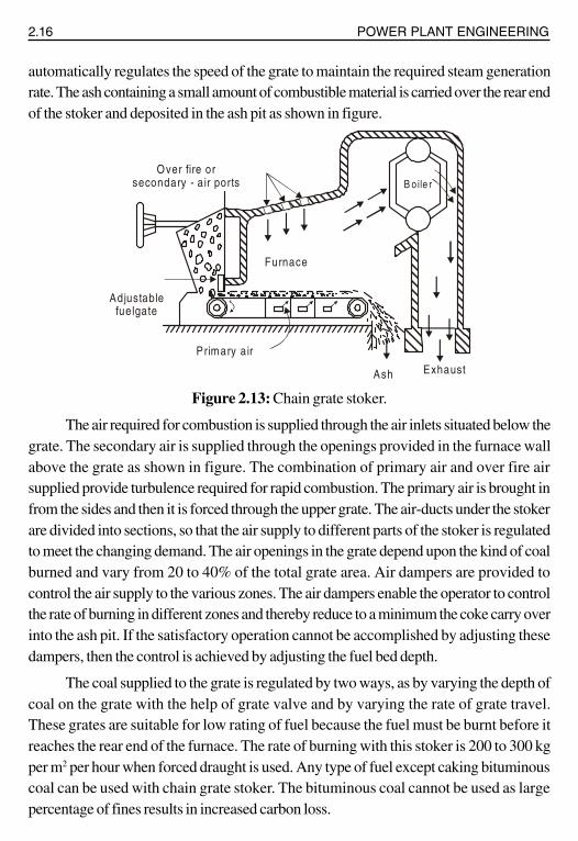
automatically regulates the speed of the grate to maintain the required steam generationrate. The ash containing a small amount of combustible material is carried over the rear endof the stoker and deposited in the ash pit as shown in figure.
Figure 2.13: Chain grate stoker.
The air required for combustion is supplied through the air inlets situated below thegrate. The secondary air is supplied through the openings provided in the furnace wallabove the grate as shown in figure. The combination of primary air and over fire airsupplied provide turbulence required for rapid combustion. The primary air is brought infrom the sides and then it is forced through the upper grate. The air-ducts under the stokerare divided into sections, so that the air supply to different parts of the stoker is regulatedto meet the changing demand. The air openings in the grate depend upon the kind of coalburned and vary from 20 to 40% of the total grate area. Air dampers are provided tocontrol the air supply to the various zones. The air dampers enable the operator to controlthe rate of burning in different zones and thereby reduce to a minimum the coke carry overinto the ash pit. If the satisfactory operation cannot be accomplished by adjusting thesedampers, then the control is achieved by adjusting the fuel bed depth.
The coal supplied to the grate is regulated by two ways, as by varying the depth ofcoal on the grate with the help of grate valve and by varying the rate of grate travel.These grates are suitable for low rating of fuel because the fuel must be burnt before itreaches the rear end of the furnace. The rate of burning with this stoker is 200 to 300 kgper m2 per hour when forced draught is used. Any type of fuel except caking bituminouscoal can be used with chain grate stoker. The bituminous coal cannot be used as largepercentage of fines results in increased carbon loss.
Over fire or secondary - a ir ports
Adjustable fuelgate
Primary air
Ash Exhaust
Furnace
B oile r
STEAM POWER PLANT 2.17
The advantages and disadvantages of chain grate stoker are listed below.
Advantages
1. It is simple in construction and its initial cost is low.
2. It is more reliable in service therefore maintenance charges are low.
3. It is self-cleaning stoker.
4. The heat release rates can be controlled just by controlling the speed of chain.
5. It gives high heat release rates per unit volume of the furnace.
Disadvantages
1. The amount of coal carried on the grate is small as the increase in grate sizecreates additional problems. This cannot be used for high capacity boilers(200 tons/hr. or more).
2. The temperature of preheated air is limited to 180ºC.
3. The clinker troubles are very common.
4. Ignition arches are required.
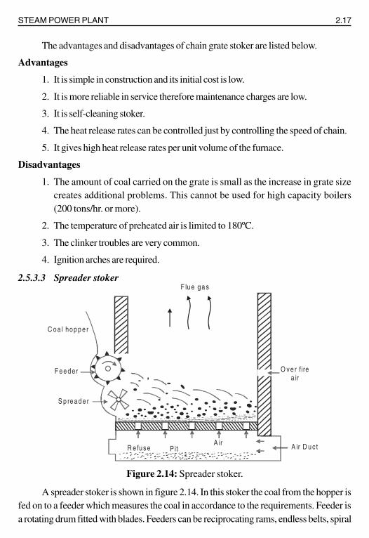
2.5.3.3 Spreader stoker
Figure 2.14: Spreader stoker.
A spreader stoker is shown in figure 2.14. In this stoker the coal from the hopper isfed on to a feeder which measures the coal in accordance to the requirements. Feeder isa rotating drum fitted with blades. Feeders can be reciprocating rams, endless belts, spiral
O ve r firea ir
C o a l ho p p e r
F e e d er
S p re a d e r
A ir D u c tA irR e fu se P it
F lu e g a s
2.18 POWER PLANT ENGINEERING
worms etc. From the feeder the coal drops on the spreader distributor which spread thecoal over the furnace. The spreader system should distribute the coal evenly over theentire grate area. The spreader speed depends on the size of coal.
Advantages
The various advantages of spreader stoker are as follows:
1. Its operation cost is low.
2. A wide variety of coal can be burnt easily by this stoker.
3. A thin fuel bed on the grate is helpful in meeting the fluctuating loads.
2.5.3.4 Vibrating grate stoker
The stoker shakes the fuel bed intermittently, the frequency and amplitude ofvibration depending on boiler load. The fuel bed is inclined so that the fuel movestowards the rear of the boiler by gravity with the progress of combustion and then fallsinto the ash pit. The grate is water-cooled to prevent slagging.
2.5.4 Method of Feeding Coal to Combustion Chamber
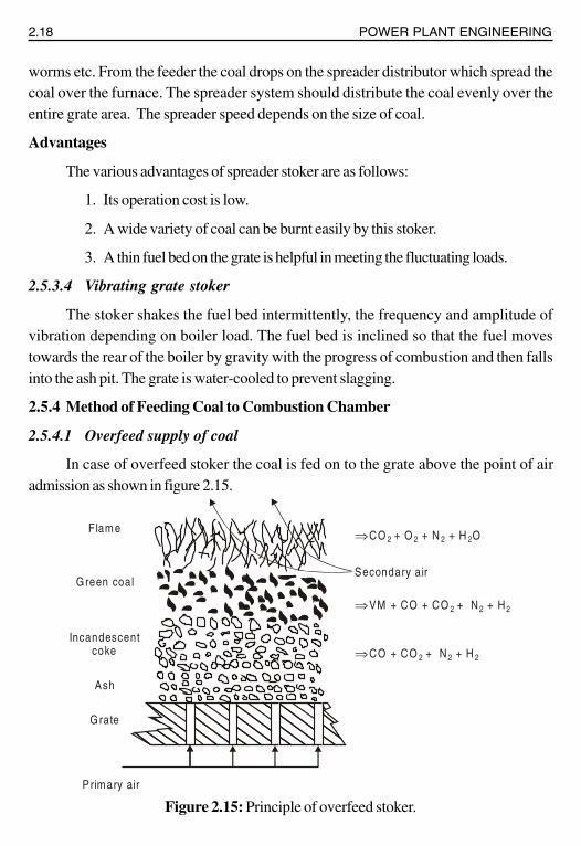
2.5.4.1 Overfeed supply of coal
In case of overfeed stoker the coal is fed on to the grate above the point of airadmission as shown in figure 2.15.
Figure 2.15: Principle of overfeed stoker.
Primary air
Grate
Ash
Incandescentcoke
Green coalSecondary air
F lame ⇒ CO + O + N + H O 2 2 2 2
⇒ VM + CO + CO + N + H 2 2 2
⇒ CO + CO + N + H 2 2 2

STEAM POWER PLANT 2.19
The mechanics of combustion in overfeed stoker is described below.
1. The pressurised air coming from F.D. fan enters under the bottom of thegrate. The air passing through the grate is heated by absorbing the heat fromthe ash and grate itself, whereas the ash and grate are cooled. The hot airthen passes through a bed of incandescent coke. As the hot air passes throughincandescent coke, the O2 reacts with C to form CO2. The rate of carbon-oxidation in this part of fuel bed depends entirely on the rate of air supply.Generally, for a fuel of 8 cm deep, all the O
2 in the air disappears in the
incandescent region. The water vapour carried with air also reacts with C inincandescent zone and forms CO, CO
2 and H
2. Part of CO
2 formed reacts
with C passing through incandescent zoen and converts into CO. The gasesleaving the incandescent region of fuel bed consist of N2, CO2, CO, H2 andH
2O.
2. The raw coal is continuously supplied on the surface of the bed. Here it losesits volatile matter by distillation. The heat required for the distillation of coal isgiven by incandescent coke below the fresh fuel, hot gases diffusing throughthe surface of bed and hot gases and flame in the furnace above. The ignitionzone lies directly below the raw fuel undergoing distillation.
3. The gases leaving the upper surface of the fuel bed contain combustible volatilematter formed from the raw fuel, N
2, CO
2, CO, H
2 and H
2O. Additional
secondary air is supplied at a very high speed to create turbulence which isrequired for complete combustion of unburned gases. The combustion of theremaining combustible gases is completed in the combustion chamber.
4. The burned gases entering the boiler contain N2, CO
2, O
2 and H
2O and some
CO if the burning is incomplete.
5. During incandescence, the fuel continuously loses its carbon by oxidation untilonly the ash remains. The primary air supplied from the bottom cools the ashuntil it rests on a plane immediately adjacent to the grate.
2.5.4.2 Under-feed stoker
In this type of stokers, the fuel and air move in the same direction. The mechanismof combustion in under-feed stoker is described below:

2.20 POWER PLANT ENGINEERING
1. Air after passing through the holes in the grate as shown in figure 2.16 meetsthe raw coal. As it diffuses through the bed of raw coal, it meets with thevolatile matter generated by the raw-coal. The heat for distillation comes byconduction from the mass of incandescent fuel bed which exists above theraw coal. The air mixes with the formed volatile matter and passes throughthe ignition zone and then enters into the region of incandescent coke.
Figure 2.16: Underfeed supply of coal.
2. The reactions which take place in the incandescent zone of under-feed stokerare exactly the same as in the incandescent zone of over-feed stoker exceptsome breaking of the molecular structure of the volatile matter takes placeand part of the broken volatile matter reacts with the oxygen of air.
3. The gases coming out of raw fuel bed pass through a region of incandescentash on the surface of the fuel and finally discharged to the furnace with theconstituents like over-feed stoker.
4. The supply of secondary air is required in this case as the gases coming out offuel bed also contain combustible matter.
5. The ash left at the bottom of the stoker is at a higher temperature than theover-feed stoker.
a) Single retort stoker
The arrangement of single retort stoker is shown in figure 2.17 (a) and 2.17 (b) inform of two views. The fuel is placed in large hopper on the front of the furnace, and then
Primary air Primary air
Ash
Incandescentcoke
Green coal
F lame ⇒ CO + O + N + H O2 2 2 2
⇒ VM + CO + CO + N + H2 2 2
Secondary air

2.24 POWER PLANT ENGINEERING
Bottom and slag may be used as filling material for road construction. Fly ash canpartly replace cement for making concrete. Bricks can be made with fly ash. These aredurable and strong.
2.7 ASH HANDLING EQUIPMENT
Mechanical means are required for the disposal of ash. The handling equipmentshould perform the following functions: 1) Capital investment, operating and maintenancecharges of the equipment should be low. 2) It should be able to handle large quantities ofash. 3) Clinkers, soot, dust etc. create troubles. The equipment should be able to handlethem smoothly. 4) The equipment used should remove the ash from the furnace, load it tothe conveying system to deliver the ash to a dumping site or storage and finally it shouldhave means to dispose of the stored ash. 5) The equipment should be corrosion and wearresistant.
Figure 2.21: Ash handling equipment.
2.8 CLASSIFICATION OF ASH HANDLING SYSTEM
i) Hydraulic system.
ii) Pneumatic system.
iii) Mechanical system.
Ashhandilingsystem
Furance
Ash
Dust, soot, fly ash collector
ID fan
Chim ney
Ash dischargeequipment
Furnace

STEAM POWER PLANT 2.25
The commonly used ash discharge equipment is as follows:
i) Rail road cars. ii) Motor truck. iii) Barge.
2.8.1 Hydraulic System
In this system, ash from the furnace grate falls into a system of water possessing highvelocity and is carried to the sumps. It is generally used in large power plants. Hydraulicsystem is of two types, namely, low pressure hydraulic system used for intermittent ashdisposal. Figure 2.22 shows hydraulic system.
Figure 2.22: Hydraulic system.
In this method water at sufficient pressure is used to take away the ash to sump.Where water and ash are separated. The ash is then transferred to the dump site inwagons, rail cars ro trucks. The loading of ash may be through a belt conveyor, grabbuckets. If there is an ash basement with ash hopper the ash can fall, directly in ash car orconveying system.
2.8.2 Water-Jetting System
Figure 2.23: Water jetting.
B o ilers
B o ilers
S u m ps
W a te r
S to ke r
Q u e n chin g n ozz le
F u ra n ce
A sh
T. R o ug h
Furnace

2.26 POWER PLANT ENGINEERING
Water jetting of ash is shown in figure 2.23. In this method a low pressure jet ofwater coming out of the quenching nozzle is used to cool the ash. The ash falls into atrough and is then removed.
2.8.3 Pneumatic System
In this system (figure 2.24) ash from the boiler furnace outlet falls into a crusherwhere larger ash particles are crushed to small sizes. The ash is then carried by a highvelocity air or steam to the point of delivery. Air leaving the ash separator is passedthrough filter to remove dust etc. so that the exhauster handles clean air which will protectthe blades of the exhauster.
Figure 2.24: Pneumatic system.
2.8.4 Mechanical System
Figure 2.25: Mechanical system.
Air
Ash
AshHopper
ExhaustFan
Filter
ASHSeparators
Boiler
C rusher
Tru ck
B u n ker
A sh
B o iler fu rn a ce s
A sh A sh
W ate r trou gh
B e lt co n ve ye r
STEAM POWER PLANT 2.27
Figure 2.25 (a) shows a mechanical ash handling system. In this system ash cooledby water seal falls on the belt conveyer and is carried out continuously to the bunker. Theash is then removed to the dumping site from the ash banker with the help of trucks.
2.9 ELECTROSTATIC PRECIPITATOR (ESP)For power generation steam power plant mainly depend on coal and other fossil
fuels to produce electricity. A natural result from the burning of fossil fuels, particularlycoal, is the emission of flyash. Ash is mineral matter present in the fuel. For a pulverizedcoal unit, 60-80% of ash leaves with the flue gas. Historically, flyash emissions have receivedthe greatest attention since they are easily seen leaving smokestacks.
Two emission control devices for flyash are the traditional fabric filters and the morerecent electrostatic precipitators. The fabric filters are large baghouse filters having a highmaintenance cost (the cloth bags have a life of 18 to 36 months, but can be temporarilycleaned by shaking or back flushing with air). These fabric filters are inherently largestructures resulting in a large pressure drop, which reduces the plant efficiency.
An electrostatic precipitator (ESP), or electrostatic air cleaner is a particulatecollection device that removes particles from a flowing gas (such as air) using the force ofan induced electrostatic charge. Electrostatic precipitators are highly efficient filtrationdevices that minimally impede the flow of gases through the device, and can easily removefine particulate matter such as dust and smoke from the air stream.
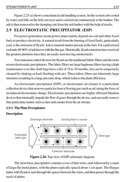
2.9.1 The Plate Precipitator
Description
Figure 2.26: Top view of ESP schematic diagram.
The most basic precipitator contains a row of thin wires, and followed by a stackof large flat metal plates, with the plates typically spaced about 1 cm apart. The fluegasladen with flyash is sent through the spaces between the wires, and then passes through thestack of plates.
Discharge electrode Ionizing filed or corona
Collection electrode
Particulateladen gas
Clean gas

2.28 POWER PLANT ENGINEERING
A negative voltage of several thousand volts is applied between wire and plate. Ifthe applied voltage is high enough an electric discharge ionizes the air around the electrodes.Negative ions flow to the plates and charge the gas-flow particles.
The particles are then routed past positively charged plates, or grounded plates,which attract the now negatively-charged ash particles. The particles stick to the positiveplates until they are collected. The air that leaves the plates is then clean from harmfulpollutants. Just as the spoon picked the salt and pepper up from the surface they were on,the electrostatic precipitator extracts the pollutants out of the air.
Figure 2.27: Side view of ESP schematic diagram.
Electrostatic precipitators have collection efficiency of 99%, but do not work wellfor flyash with a high electrical resistivity (as commonly results from combustion of low-sulfur coal). In addition, the designer must avoid allowing unburned gas to enter theelectrostatic precipitator since the gas could be ignited.
With electrostatic precipitators, if the collection plates are allowed to accumulatelarge amounts of particulate matter, the particles often bond so tightly to the metal platesthat vigorous washing and scrubbing may be required to completely clean the collectionplates. The close spacing of the plates can make thorough cleaning difficult, and the stackof plates often cannot be easily disassembled for cleaning.
Some consumer precipitation filters are sold with special soak-off cleaners, wherethe entire plate array is removed from the precipitator and soaked in a large containerovernight, to help loosen the tightly bonded particulates.
High voltagepower supply Rappers
Clean gas tosmokestack
Hoppers
Metal collectionplates
Particulateladen flue gas

STEAM POWER PLANT 2.29
Electrostatic precipitators are not only used in utility applications but also otherindustries (for other exhaust gas particles) such as cement (dust), pulp and paper (saltcake and lime dust), petrochemicals (sulfuric acid mist), and steel (dust & fumes).
2.9.2 Wet Electrostatic Precipitator
Electrostatic precipitation is typically a dry process, but spraying moisture to the incomingair flow helps collect the exceptionally fine particulates, and helps reduce the electricalresistance of the incoming dry material to make the process more effective.
A wet electrostatic precipitator (WESP) merges the operational methods of a wetscrubber with an electrostatic precipitator to make a self-washing, self-cleaning yet stillhigh-voltage device.
Advantages
1. This is more effective to remove very small particles like smoke, mist and flyash.Its range of dust removal is sufficiently large (0.01 μ to 1.00 μ). The small dustparticles below 10 μ cannot be removed with the help of mechanical separatorsand wet scrubbers cannot be used if sufficient water is not available. Underthese circumstances, this type is very effective.
2. This is also most effective for high dust loaded gas (as high as 100 grams per cumetre). Its efficiency is as high as 99.5%.
3. The draught loss of this separator is the least of all forms (1 cm of water).
4. The maintenance charges are least among all separators.
5. It provides ease of operation.
6. The dust is collected in dry form and can be removed either dry or wet.
Disadvantages
1. The direct current is not available with the modern power plants, therefore,considerable electrical equipment is necessary to convert low voltage (400 V)A.C. to high voltage (60,000) D.C. This increases the capital cost of theequipment as high as 40 to 60 cents per 1000 kg of rated installed steam generatingcapacity.
2. The running charges are also considerably high as the amount of power requiredfor charging is considerably large.
3. The space required is larger than wet system.

2.30 POWER PLANT ENGINEERING
4. The efficiency of the collector is not maintained if the gas velocity exceeds thatfor which the plant is designed. The dust carried with the gases increases with anincrease of gas velocity. The efficiency decreases from 100 to 80% when thegas flow increases from 1000 m3/min to 60 × 1000 m3/min.
5. Because of the closeness of the charged plates and potential used, it is necessaryto protect the entire collector from sparking by providing a fine mesh before theionising chamber. This is necessary because even the smallest piece of papermight cause sparking when it would be carried across adjacent plates or wires.
2.10 DRAUGHT
Draught is defined as the difference between absolute gas pressure at any point in agas flow passage and the ambient (same elevation) atmospheric pressure. Draught is plusif Patm < Pgas and it is minus Patm > Pgas. Draught is achieved by small pressure differencewhich causes the flow of air or gas to take place. It is measured in milimetre (mm) ofwater.
The purpose of draught is as follows:
i) To supply required amount of air to the furnace for the combustion of fuel.The amount of fuel that can be burnt per square foot of grate area dependsupon the quantity of air circulated through fuel bed.
ii) To remove the gaseous products of combustion.
2.11 CLASSIFICATION OF DRAUGHT
The following flow chart gives the classification of draughts:
Natural draught
Draught
Artific ia l draught
Steam jet Mechanical draught (fan draught)
Induceddraught
Forced draught(turbine draught)
Induced fandraught
Balanceddraught
Forced fandraught

STEAM POWER PLANT 2.31
If only chimney is used to produce the draught, it is called natural draught.
Artificial draught
If the draught is produced by steam jet or fan it is known as artificial draught.
Steam jet draught
It employs steam to produce the draught.
Mechanical draught
It employs fan or blowers to produce the draught.
Induced draught
The flue is drawn (sucked) through the system by a fan or steam jet.
Forced draught
The air is forced into the system by a blower or steam jet.
2.12 NATURAL DRAUGHTNatural draught system employs a tall chimney as shown in figure 2.28. The chimney
is a vertical tubular masonry structure or re-inforced concrete. It is constructed for enclosinga column of exhaust gases to produce the draught. It discharges the gases high enough toprevent air pollution. The draught is produced by this tall chimney due to the temperaturedifference of hot gases in the chimney and cold external air outside the chimney.
Figure 2.28: Natural draught.
Where H - Height of the chimney (m).
pa - Atmospheric pressure (N/m2).
p1
- Pressure acting on the grate from chimney side (N/m2).
p2
- Pressure acting on the grate from atmospheric side (N/m2).
Col
umn
of
hot g
ases
Col
umn
of c
ool
atm
. air
Furnace grate level
2
1
Pa Pa
H
P1 P2

2.32 POWER PLANT ENGINEERING
Due to this pressure difference (p), the atmospheric air flows through the furnacegrate and the flue gases flow through the chimney. The pressure difference can be increasedby increasing the height of the chimney or reducing the density of hot gases.
2.12.1 Merits of Natural Draught
1. No external power is required for creating the draught.
2. Air pollution is prevented since the flue gases are discharged at a higher level.
3. Maintenance cost is practically nil since there are no mechanical parts.
4. It has longer life.
5. Capital cost is less than that of an artificial draught.
Demerits of natural draught
1. Maximum pressure available for producing draught by the chimney is less.
2. Flue gases have to be discharged at higher temperature since draught increaseswith the increase in temperature of flue gases.
3. Heat cannot be extracted from the flue gases for economiser, superheater, airpre-heater, etc. since the effective draught will be reduced if the temperature ofthe flue gases is decreased.
4. Overall efficiency of the plant is decreased since the flue gases are discharged athigher temperatures.
5. Poor combustion and specific fuel consumption is increased since the low velocityof air affects thorough mixing of air and fuel.
6. Not flexible under peak loads since the draught available for a particular heightof a chimney is constant.
7. A considerable amount of heat released by the fuel (about 20%) is lost due toflue gases.
2.12.2 Applications
Natural draught system is used only in small capacity boilers and it is not used in highcapacity thermal plants.
2.12.3 Calculations of Chimney Height
Let m = Mass of air supplied per kg of fuel.
Tg
= Average absolute temperature of chimney gases in K.
Ta
= Absolute temperature of the outside the chimney in K.
Therefore the mass of the flue gases formed = (m + 1) kg per kg of fuel burnt.

STEAM POWER PLANT 2.33
Since the volume of solid or liquid fuel burnt is small as compared to the volume ofair supplied, it may be neglected. The volume of chimney gases produced may be taken asequal to the volume of air supplied.
One kg of air occupies 0.7734 m3 at N.T.P.
Volume per kg of air at temperatur Ta K
= 0.7734 × aT
273
∴ Volume of m kg of air at Ta K = a0.7734 × m × T
273
Density of air at Ta K =a
Mass m 273
Volume 0.7734 m T
×=× ×
3
aa
353kg / m
Tρ =
Since the volume of gas is proportionate to its absolute temperature (by Charles’law),
Volume of chimney gases at Tg K =
g0.7734 m T
273Similarly,
Density of chimney gases at Tg K Mass of the gas
Volume of the gas=
( )
g
m 1 273
0.7734 m T
+ ×=
( ) 3
gg
m 1353· kg / m
T m
+ρ =
Let H be the height of the chimney in metres measured from the grate level, h be thedraught pressure in mm of water, and A be the area of the furnace grate in m2.
∴ Pressure exerted by a column of hot chimney gas of H metre height

2.34 POWER PLANT ENGINEERING
Figure 2.29: Chimney draught.
P = density × 9.81 × H N/m2
2
g
353 m 1· · 9.81 H N / m
T m
+⎛ ⎞ ×⎜ ⎟⎝ ⎠
Similarly, pressure exerted by a column of cold outside air of the same area and Hmetre height
2
a
3539.81 H N / m
T× ×
Let P = Pressure causing the draught in N/m2.
As the pressure causing the draught is due to the pressure difference due to columnof hot gases inside the chimney and the pressure due to an equal column of outside cold air,
( )
a g
m 1353 353P 9.81H ·
T T m
⎛ ⎞+= −⎜ ⎟⎜ ⎟⎝ ⎠
( )
a g
m 11 1353 9.81 H ·
T T m
⎛ ⎞+= × −⎜ ⎟⎜ ⎟⎝ ⎠
...(1)
We know that P = ρ gh = 2h1000 9.81 9.81h N / m
1000× × =
Substitute this value in equation (1)
( )
a g
m 11 19.81 h 353 9.81 H ·
T T m
⎛ ⎞+= × −⎜ ⎟⎜ ⎟⎝ ⎠
Boiler
Level of grate
H
Col
umn
of c
old
air
Chim ney
Equ
ival
ent c
olum
n of
hot
air
Col
umn
of h
ot g
as
h g

STEAM POWER PLANT 2.35
( )
a g
m 11 1h 353 H mm of water
T T m
⎛ ⎞+= −⎜ ⎟⎜ ⎟⎝ ⎠
...(2)
Equation (2) can be modified to express the draught in terms of column of hot gases.Let h
g be the height of column of hot gases which will produce the pressure P.
∴ Pressure exerted by this column of hot gases,
P = density × 9.81 × hg
gg
353 m 1P 9.81 h
T m
+⎛ ⎞= × ×⎜ ⎟⎝ ⎠ ...(3)
Equating equation (3) and (1)
( )g
g a g
m 1353 m 1 1 19.81 h 353 9.81 H
T m T T m
⎛ ⎞++⎛ ⎞ × × = × −⎜ ⎟⎜ ⎟ ⎜ ⎟⎝ ⎠ ⎝ ⎠
g
ga
Tmh H · 1
m 1 T
⎡ ⎤= −⎢ ⎥+⎣ ⎦
...(4)
Calculations of chimney diameter
The velocity of the gases passing through the chimney is given by gV 2gh=
assuming there is no loss.If the pressure loss in the chimney due to friction is equaivalent to h
f.
The velocity of flue gases in the chimney,
( )g fV 2g h h= −
( )g f2 9.81 h h= × −
fg
g
h4.43 h 1
h
⎛ ⎞= −⎜ ⎟⎜ ⎟⎝ ⎠
gK h=

2.36 POWER PLANT ENGINEERING
Where f
g
hK 4.43 1
h= −
K = 0.825 for brick chimney
K = 1.1 for steel chimney.
The mass of gases flowing through any cross section of the chimney is given by
mg = A × V × ρg kg/s
2g gD V m
4
π∴ × × ρ =
g
g
mD 1.128
V.=
ρ
Where D is the diameter at any cross section of the chimney.
Condition for maximum discharge through the chimney
( )
g a
m 1T 2.T
m
+= ...(5)
Substitute equation (5) in (4)
Equation (4) becomes, ( )a
ga
2.T m 1 mh H 1
T m 1
+⎡ ⎤= × −⎢ ⎥+⎣ ⎦
= H (2 – 1)
= H metres
Therefore, when maximum discharge takes place the height of the coloumn ofhot gas which would produce a draught will be equal to the height of the chimney. Bysubstituting the value of T
g in equation (2), we get
a
176.5 Hh
T=
2.13 ARTIFICIAL DRAUGHTIt has been seen that the draught produced by chimney is affected by the atmospheric
conditions. It has no flexibility, poor efficiency and tall chimney is required. In most of the

STEAM POWER PLANT 2.37
modern power plants, the draught used must be independent of atmospheric condition,and it must have greater flexibility (control) to take the fluctuating loads on the plant.
Today’s large steam power plants requireing 20 thousand tons of steam per hourwould be impossible to run without the aid of draft fans. A chimney of any reasonableheight would be incapable of developing enough draft to move the tremendous volume ofair and gases (400 × 103 m3 to 800 × 103 m3 per minute). The further advantage of fans isto reduce the height of the chimney needed.
The draught required in actual power plant is sufficiently high (300 mm of water)and to meet high draught requirements, some other system must be used, known as artificaldraught. The artificial draught is produced by a fan and it is known a fan (mechanical)draught. Mechanical draught is preferred for central power stations.
2.13.1 Forced Draught
In a forced draught system, a blower is installed near the base of the boiler and airis forced to pass through the furnace, flues, economiser, air-preheater and to the stack.This draught system is known as positive draught system or forced draught systembecause the pressure and air is forced to flow through the system. The arrangement ofthe system is shown in figure 2.30. A stack or chimney is also used in this system as shownin figure but its function is to discharge gases high in the atmosphere to prevent thecontamination. It is not much significant for producing draught therefore height of thechimney may not be very much.
Figure 2.30: Forced draught.
2.13.2 Induced Draught
In this system, the blower is located near the base of the chimney instead of near thegrate. The air is sucked in the system by reducing the pressure through the system below
Blower
Boiler
Furnace
Grate
AirPreheater
Ecnomiser
ToExhaust
Stack orChim ney
Economiser

2.38 POWER PLANT ENGINEERING
atmosphere. The induced draught fan sucks the burned gases from the furnace and thepressure inside the furnace is reduced below atmosphere and induces the atmospheric airto flow through the furnace. The action of the induced draught is similar to the action of thechimney. The draught produced is independent of the temperature of the hot gases thereforethe gases may be discharged as cold as possible after recovering as much heat as possiblein air-preheater and economiser.
This draught is used generally when economiser and air-preheater are incorporatedin the system. The fan should be located at such a place that the temperature of the gashandled by the fan is lowest. The chimney is also used in this system and its function issimilar as mentioned in forced draught but total draught produced in induced draught systemis the sum of the draughts produced by the fan and chimeny. The arrangement of thesystem is shown in figure 2.31.
Figure 2.31: Induced draught.
2.13.3 Balanced Draught
It is always preferable to use a combination of forced draught and induced draughtinstead of forced or induced draught alone.
If the forced draught is used alone, then the furnace cannot be opened either forfiring or inspection because the high pressure air inside the furnace will try to blow outsuddenly and there is every chance of blowing out the fire completely and furnace stops.
If the induced draught is used alone, then also furnace cannot be opened either forfiring or inspection because the cold air will try to rush into the furnace as the pressureinside the furnace is below atmospheric pressure. This reduces the effective draught anddilutes the combustion.
Chim ney
ToExhaust
Boiler
Furnace
GrateEcnomiser
AirPreheater
B lower
Air inAir in
Economiser

STEAM POWER PLANT 2.39
Figure 2.32: Balanced draught.
To overcome both the difficulties mentioned above either using forced draught orinduced draught alone, a balanced draught is always preferred. The balanced draught is acombination of forced and induced draught. The forced draught overcomes the resistanceof the fuel bed therefore sufficient air is supplied to the fuel bed for proper and completecombustion. The induced draught fan removes the gases from the furnace maintainingthe pressure in the furnace just below atmosphere. This helps to prevent the blow-off offlames when the doors are opened as the leakage of air is inwards.
The arrangement of the balanced draught is shown in figure 2.32. Also the pressureinside the furnace is near atmospheric therefore there is no danger of blowout or there is nodanger of inrushing the air into the furnace when the doors are opened for inspection.
2.14 COMPARISON OF FORCED AND INDUCED DRAUGHT
S.No Forced draught Induced draught
1. The size and power required The size and power required byby the F.D. fan is less. I.D. fan is more.
2. Volume of gas handled is less. Volume of gas handled is more.
3. Water cooled bearings are not Water cooled bearings are required torequired. withstand high temperature flue gas.
4. There is no chance of air leakage Continuous air leakage is possible asas the pressure inside the furnace the pressure inside the furnace is lessis above atmospheric. than atmosphere.
5. The flow of air through the grate Flow of air is not uniform.and furnace is uniform.
6. The heat transfer efficiency will There may a chance of reduction inbe increased. heat transfer efficiency.
Chim ney
Boiler
Furnace
GrateEcnomiser
AirPreheater
I.D fanF.D fan
Economiser

2.40 POWER PLANT ENGINEERING
2.15 MERITS AND DEMERITS OF MECHANICAL DRAUGHT OVER NATURAL DRAUGHT
S.No Mechanical draught Natural (chimney) draught
Merits: Demerits:
1. Evaporative capacity is increased Evaporative capacity is less sincesince draught is more and the rate draught is less.of combustion in increased.
2. Low grade fuel can be used since High grade fuels are used.the intensity of mechanical draughtis more.
3. Independent of atmospheric Dependent on atmospherictemperature. temperature.
4. Better control of combustion and Combustion cannot be controlledevaporation since the air flow can since air flow cannot be regulated.be regulated to suit the combustion.
5. Thermal efficiency of the plant is Thermal efficiency of the plant ismore since heat in flue gases can be less since the flue gases have to berecovered using economiser, air discharged at high temperatures.pre-heater etc).
6. Chimney height is reduced since Chimney height is more to have thethe function of the chimney is only required draught.to discharge flue gases at aconvenient height in the atmosphere.
7. Fuel consumption for the given Fuel consumption for the givenpower is less. power is more.
8. Used in high capacity power plants. Used in small capacity boilers.Demerits: Merits:
1. External power is required to drive No external power is needed tothe fan. for the draught.
2. Capital cost is high. Capital loss is less.
3. Running and maintenance costs Maintenance cost is practically nil(of the fan) are high. since there are no mechanical parts.

STEAM POWER PLANT 2.41
2.16 STEAM JET DRAUGHT
The artificial draught produced by the steam jet is known as steam jet draught.They may be induced or forced depending upon the location of the steam jet.
Induced steam jet draught
In this type, the exhaust steam from the engine is forced into the smoke box througha nozzle (figure 2.33 (a)). When the steam flows through the nozzle, a partial vacuum iscreated and the air is induced to the furnace through the flues and grate.
(a) Induced steam jet draught. (b) Forced steam jet draught.
Figure 2.33
Forced steam jet draught
In this system, steam passes through a throttle valve from the boiler. Then the steampasses through a nozzle which is projecting into a diffuser pipe (figure 2.33 (b)). Thesteam comes out of the nozzle with high velocity and draws air along with it. The kineticenergy of the mixture of steam and air is converted into pressure energy when it passesthrough the diffuser pipe. Thus air is forced through the fuel bed, furnace and passedthrough the chimney.
Thr
ottle
val
ve
S ie a m
D iffuse r
G ra te
N o zz le
Sta ck
Ste am n o zzle
Air
suck
ed in
E xh a us t s te a m fro m s te am e n g in e
Steam

2.42 POWER PLANT ENGINEERING
Merits of steam jet draught
1. This system is very simple and low in cost.
2. Low grade fuels can be used.
3. Space required is less.
Demerits of steam jet draught
1. It can be operated only when the steam is raised.
2. The draught produced is very low.
2.17 CONDENSERA condenser is a device in which the steam is condensed by cooling it with water.
The condensed steam is known as condensate. The following are the advantages of installinga condenser in a steam power plant.
1. More work is done by the given amount of steam than could be obtainedwithout a condenser. Thus, the efficiency of the power plant is increased.
2. Steam consumption is reduced for the given output.
3. The condensate is recovered for the boiler feed water.
The steam power plants using condenser are shown in figure 2.34 (a) shows that thecooling water used in condenser is not re-circulated again and again but discharged to thedownstream side of the river. Whereas figure 2.34 (b) shows that the cooling water isre-circulated again and again by passing through the cooling tower.
The essential elements of a steam condensing plant is given below:
1. A closed vessel in which the steam is condensed.
2. A pump to deliver condensed steam to the hot well from the condenser.
3. A dry air-pump to remove air and other non-condensable gases.
4. A feed pump to deliver water to the boiler from hot well.
5. Another pump for circulating cooling water.
6. An arrangement for re-cooling the circulating water from the condenser suchas cooling tower or spray pond.

STEAM POWER PLANT 2.43
(a) Open cycle condensing system
(b) Closed cycle condensing system
Figure 2.34
Condenser
Steam turbine
Condenserpump
River
Cooling waterpump
To air pump
Boiler
C o n d e nse r
P u m p
Steam turbine
Condenser
R ive r
Make up water pump
Cooling tower
B o iler
C o o lin g w a te rp u m p
2.44 POWER PLANT ENGINEERING
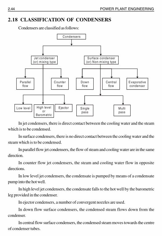
2.18 CLASSIFICATION OF CONDENSERS
Condensers are classified as follows:
In jet condensers, there is direct contact between the cooling water and the steamwhich is to be condensed.
In surface condensers, there is no direct contact between the cooling water and thesteam which is to be condensed.
In parallel flow jet condensers, the flow of steam and cooling water are in the samedirection.
In counter flow jet condensers, the steam and cooling water flow in oppositedirections.
In low level jet condensers, the condensate is pumped by means of a condensatepump into the hot well.
In high level jet condensers, the condensate falls to the hot well by the barometricleg provided in the condenser.
In ejector condensers, a number of convergent nozzles are used.
In down flow surface condensers, the condensed steam flows down from thecondenser.
In central flow surface condensers, the condensed steam moves towards the centreof condenser tubes.
Condensers
Jet condenser(or) m ixing type
Surface condenser(or) Non-m ixing type
Paralle lflow
Counter flow
Downflow
Central flow
Evaporativecondenser
Low level H igh levelor
Barom etric
E jector S ingle pass
Multipass
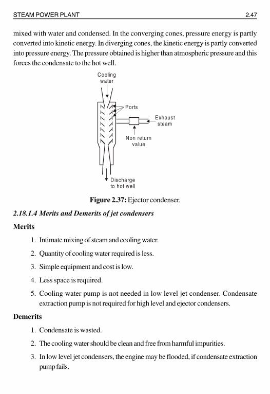
STEAM POWER PLANT 2.47
mixed with water and condensed. In the converging cones, pressure energy is partlyconverted into kinetic energy. In diverging cones, the kinetic energy is partly convertedinto pressure energy. The pressure obtained is higher than atmospheric pressure and thisforces the condensate to the hot well.
Figure 2.37: Ejector condenser.
2.18.1.4 Merits and Demerits of jet condensers
Merits
1. Intimate mixing of steam and cooling water.
2. Quantity of cooling water required is less.
3. Simple equipment and cost is low.
4. Less space is required.
5. Cooling water pump is not needed in low level jet condenser. Condensateextraction pump is not required for high level and ejector condensers.
Demerits
1. Condensate is wasted.
2. The cooling water should be clean and free from harmful impurities.
3. In low level jet condensers, the engine may be flooded, if condensate extractionpump fails.
Non returnvalue
Exhauststeam
Ports
Coolingwater
D ischargeto hot well

STEAM POWER PLANT 2.49
The arrangement of the surface condenser is shown in figure 2.39. It consists ofcast iron air-tight cylindrical shell closed at each end as shown in figure. A number ofwater tubes are fixed in the tube plates which are located between each cover head andshell.
Figure 2.39: Surface condenser.
The exhaust steam from the prime mover enters at the top of the condenser andsurrounds the condenser tubes through which cooling water is circulated under force. Thesteam gets condensed as it comes in contact with cold surface of the tubes. The coolingwater flows in one direction through the first set of the tubes situated in the lower half ofcondenser and returns in the opposite direction through the second set of the condeser isdischarged into the river or pond. The condensed steam is taken out from the condenserby a separate extraction pump and air is removed by an air pump.
2.18.2.2 Central flow condenser
Figure 2.40 shows a central flow condenser. In this condenser the steam passagesare all around the periphery of the shell. Air is pumped away from the centre of thecondenser. The condensate moves radially towards the centre of tube next. Some of theexhaust steam while moving towards the centre meets the undercooled condensate andpre-heats it thus reducing undercooling.
Tube plate
To condensa tepum p
Water box
Exhauststeam
Cooling w ateroutlet
Water box
Cooling w aterInlet
To air pump
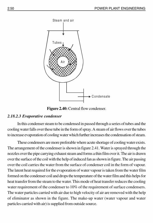
2.50 POWER PLANT ENGINEERING
Figure 2.40: Central flow condenser.
2.18.2.3 Evaporative condenser
In this condenser steam to be condensed in passed through a series of tubes and thecooling water falls over these tube in the form of spray. A steam of air flows over the tubesto increase evaporation of cooling water which further increases the condensation of steam.
These condensers are more preferable where acute shortage of cooling water exists.The arrangement of the condenser is shown in figure 2.41. Water is sprayed through thenozzles over the pipe carrying exhaust steam and forms a thin film over it. The air is drawnover the surface of the coil with the help of induced fan as shown in figure. The air passingover the coil carries the water from the surface of condenser coil in the form of vapour.The latent heat required for the evaporation of water vapour is taken from the water filmformed on the condenser coil and drops the temperature of the water film and this helps forheat transfer from the steam to the water. This mode of heat transfer reduces the coolingwater requirement of the condenser to 10% of the requirement of surface condensers.The water particles carried with air due to high velocity of air are removed with the helpof eliminator as shown in the figure. The make-up water (water vapour and waterparticles carried with air) is supplied from outside source.
Tubes
Condensate
Steam and air
A ir

2.52 POWER PLANT ENGINEERING
The various disadvantages of the surface condenser are as follows:
i) The capital cost is more.
ii) The maintenance cost and running cost of this condenser is high.
iii) It is bulky and requires more space.
2.19 SOURCES OF AIR IN CONDENSERSThe sources of air in a condenser are given below:
1. The exhaust steam from the turbine may contain certain amount of air. This isbecause, some air is dissolved in the feed water supplied to the boiler andcarried by the steam to the turbine.
2. Atmospheric air may leak through various joints and also through thecondenser.
3. In jet condensers, water used for cooling may contain some air.
4. Air may also leak through relief valves and other accessories.
2.20 EFFECTS OF AIR LEAKAGEThe effects of air leakage into a condenser are given below:
1. Thermal efficiency of the plant is reduced. The back pressure on the primemover is increased by the presence of air in the condenser. There is a loss ofheat drop and it reduces thermal efficiency of the plant.
2. More cooling water is required. The presence of air reduces saturationtemperature of air. This increases latent heat of steam. Hence more coolingwater is required to condense this steam.
3. Heat transfer rate is reduced because the air has poor thermal conductivity.
2.21 COOLING TOWERS2.21.1 Introduction
In the power industry, energy in the form of heat is transformed to energy in the formof electricity. Unfortunately, this transformation is not accomplished on a one-to-one ratio.Although designers continuously seek newer and better ways to improve overall systemefficiency, considerably more units of heat must be input than are realized as equivalentunits of electric output. System equilibrium requires that this excess heat be dissipatedultimately to the atmosphere.
STEAM POWER PLANT 2.53
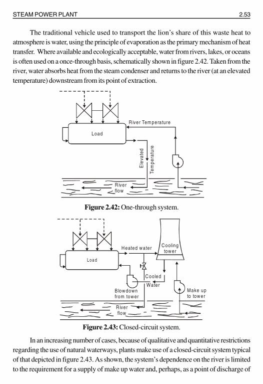
The traditional vehicle used to transport the lion’s share of this waste heat toatmosphere is water, using the principle of evaporation as the primary mechanism of heattransfer. Where available and ecologically acceptable, water from rivers, lakes, or oceansis often used on a once-through basis, schematically shown in figure 2.42. Taken from theriver, water absorbs heat from the steam condenser and returns to the river (at an elevatedtemperature) downstream from its point of extraction.
Figure 2.42: One-through system.
Figure 2.43: Closed-circuit system.
In an increasing number of cases, because of qualitative and quantitative restrictionsregarding the use of natural waterways, plants make use of a closed-circuit system typicalof that depicted in figure 2.43. As shown, the system’s dependence on the river is limitedto the requirement for a supply of make up water and, perhaps, as a point of discharge of
Load
R iver Tem perature
Tem
pera
ture
Ele
vate
d
R iverflow
Loa d
R iverflow
H eated w ater C oolingtow er
C ooled
WaterMake upto tow er
B low downfrom tow er
2.56 POWER PLANT ENGINEERING
Note that the applied heat load establishes only a required temperature differentialin the condenser-water circuit and is unconcerned with the actual hot- and cold-watertemperatures themselves. Therefore, the more indication of a heat load is meaningless tothe application engineer attempting to size a cooling tower properly. Loads must be expressedin terms of a specific flow to be cooled from an established hot-water temperature to arequired cold-water temperature. Knowing any two of these parameters, the specifiercan determine the third by a simple transposition of terms in equation (7).
Since the cooling-tower designer must also know the heat content of the air at thepoint of design, as evidenced by equation (7), the specifier must also establish the designwet-bulb temperature.
2.21.3 Types of Cooling Towers
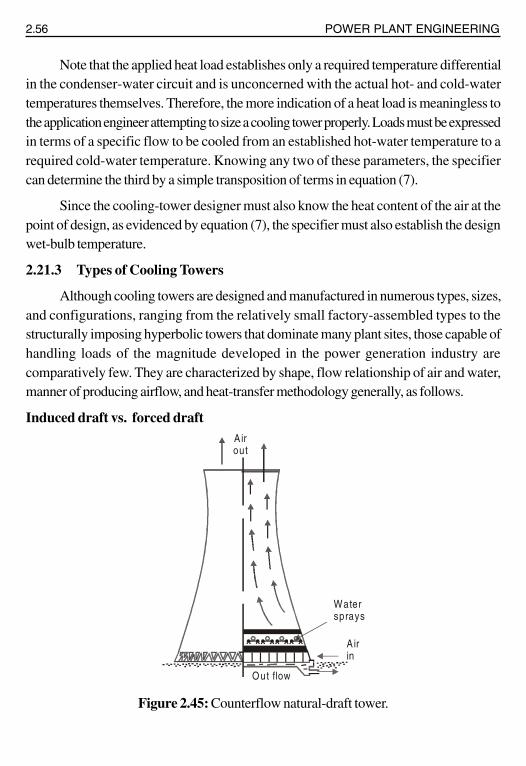
Although cooling towers are designed and manufactured in numerous types, sizes,and configurations, ranging from the relatively small factory-assembled types to thestructurally imposing hyperbolic towers that dominate many plant sites, those capable ofhandling loads of the magnitude developed in the power generation industry arecomparatively few. They are characterized by shape, flow relationship of air and water,manner of producing airflow, and heat-transfer methodology generally, as follows.
Induced draft vs. forced draft
Figure 2.45: Counterflow natural-draft tower.
Airout
Watersprays
Airin
Out flow

2.62 POWER PLANT ENGINEERING
Figure 2.54: Film-type fill.
and retardation of the water. The resultant small vertical dimension, plus relatively widevertical spacing of the splash bars, therefore provides the least opposition to airflow in thehorizontal direction typical of crossflow. Its use in counterflow towers, where airflow isessentially vertical, requires an increase in fan power, which is normally consideredunacceptable in today’s market.
Film type
Film-type fill has gained prominence in the cooling tower industry because of itsability to expose greater water surface within a given packed volume. As can be seen infigure 2.50, water flows in a thin “film” over vertically oriented sheets of fill which arespaced appropriately for either vertical or horizontal air passage. Therefore, film-type fillis equally effective in either type of cooling tower.
For purposes of clarity, the fill sheets in figure 2.55, are shown to be flat. In practice,these sheets predominantly of polyvinyl chloride (PVC) material are molded into uniquepatterns to create a certain amount of turbulence within the airstream and to further extendthe exposed water surface. The fill pack indicated in figure 2.55, for example, ismanufactured in a cross-corrugated configuration, with the contact points of the corrugationsproviding the proper spacing. Other shapes may include regular protrusions to maintainspacing.

STEAM POWER PLANT 2.63
Fill sheets
Flowingwater film
Air passages
W a te r f lo wTe m p e ra tu re
“L ”, K g /s o f w a te r
“L ”, K g /s o f w a te r
H o t w a te r, ( C )o
C o ld w a te r, ( C )o
A p p ro a c h( C )o
W e t - b u lb , ( C )o
Ran
ge, “
R”
H ea tloa d
= L x R
Load
Figure 2.55: Film-fill concept.
Although film-type fill currently predominates the cooling-tower industry, there isno present indication that splash-type fill will become obsolete in the foreseeable future.The narrow passages afforded by close spacing of fill sheets makes film fill very sensitiveto water quality. High turbidity, leaves, debris, or the presence of algae, slime, or coagulantscan diminish passage size or, in extreme cases, lead to complete plugging. In geothermalapplications, therefore, as well as installations tapping turbid water as a source of makeup,splash fill continuous to be the fill of choice.
2.21.5 Factors Affecting Tower Size and Performance
Figure 2.56: Parameters affecting tower size.

2.64 POWER PLANT ENGINEERING
4 5 6Heat load factor
Constan ts:RangeApproachW et-bu lb
1
2
3
4
5
6
1 2 3
Tow
er s
ize
fact
or
1 2 0 1 4 0 1 6 0 1 8 0 2 0 0
R a n g e va ria n ce , %
D ec rea s ing (L /s)
0 .60 .70 .8
0 .9
1 .0
1 .11 .2
1 .3
4 0 6 0 8 0 1 0 0
Tow
er s
ize
fact
or
As one might gather from a study of figure 2.56, several parameters of choice affectthe size of a cooling tower. Among these areas the system-related aspects of heat load,range, and approach; and wet-bulb temperature, which is site-related. In addition to theseparameters, site-related interference must be considered, as well as recirculation, which isinfluenced by tower design and orientation. The effect of all these factors on tower size isdiscussed here.
Heat load, range, and Approach
Figure 2.57: Effect of heat load on tower size.
Figure 2.58: Effect of varying range of tower size.
As seen in figure 2.57, at a given range, approach, and wet-bulb temperature, towersize varies directly and linearly with heat load. The larger the heat load, the bigger therequired tower will be.

STEAM POWER PLANT 2.65
Tow
er s
ize
fact
or
2 .0
1 .5
1 .0
0 .5
W et-bu lb tem peratu re (ºC )
Constants:Heat loadRangeApproach
12 15 18 21 24 27
Figure 2.59: Effect of chosen approach on tower size.
Tower size varies inversely with range (figure 2.58). Increasing the range increasesthe temperature differential between the incoming hot water and the incoming air, therebyincreasing the driving force for enthalpy exchange and reducing the size of the tower.
Tower size varies inversely with approach. A longer approach requires a smallertower (figure 2.59). Conversely, a smaller approach requires an increasingly large tower,and at an approach of 2.8ºC, the effect on tower size begins to become asymptotic. Forthat reason, it is not customary in the cooling tower industry to guarantee approaches ofless than 2.8ºC.
Wet-bulb temperature
Figure 2.60: Effect of wet-bulb temperature on tower size.
Tower size varies inversely with the design wet-bulb temperature. When heat load,range, and approach values are fixed, increasing the design wet-bulb temperature reducesthe size of the tower (figure 2.60). Since the primary exchange of heat in a cooling tower
Tow
er
size
fact
or

2.66 POWER PLANT ENGINEERING
is through evaporation, the fact that ability of air to absorb moisture increases with highertemperatures accounts for this size reduction.
In attempting to understand these effects, readers must not allow themselves tobecome confused regarding the relative relationship of cold-water temperature, wet-bulbtemperature, and approach. The inverse effect of design wet-bulb temperature on towersize applies only when approach values are held constant, that is, when the cold-watertemperature is altered in the same direction as the changed wet-bulb temperature and bythe same number of degrees.
SOLVED PROBLEMS
Problems on Draught
1. Estimate the height of a chimney required to produce a static draught of 18mm of water if the mean temperature of the flue gases in the chimney is260ºC and the temperature of outside air is 25ºC. The densities of atmosphericair and the flue gases at N.T.P. are 1.293 and 1.34 kg/m3 respectively.
Solution:
Density of air at 25ºC ( )1.293 273
25 273
×=+
= 1.184 kg/m3
Density of flue gases at 260ºC ( )1.34 273
260 273
×=+
= 0.686 kg/m3
Pressure difference is given as
P = 9.81 H (ρair – ρg) N/m2
But P = 9.81 H = 9.81 × 18 = 176.58 N/m2
∴ 176.58 = 9.81 H (1.184 – 0.686)
( )176.58
H9.81 1.184 0.686
=−
H 36.14m=

STEAM POWER PLANT 2.67
2. A 50 m high chimney is full of hot gases at a temperature of 350ºC. The airsupplied for the complete combustion of 1 kg of fuel is 18 kg. If thetemperature of the outside air is 27ºC. Find the draught: a) In terms ofcolumn of hot gases and b) In terms of water column.
Given data:
H = 50 m
Tg
= 350ºC = 350 + 273 = 623 K
m = 18 kg
Ta
= 27ºC = 27 + 273 = 300 K
Solution:
a) The draught in terms of column of hot gases is given by
gg
a
T mh H – 1
T m 1
⎡ ⎤= ×⎢ ⎥+⎣ ⎦
( )
623 1850 1
300 18 1
⎡ ⎤= × −⎢ ⎥+⎣ ⎦= 50 (0.967) = 48.35 metres of hot gas column.
b) The draught in terms of water column is given by,
( )a g
m 11 1h 353 H ·
T T m
⎡ ⎤+= −⎢ ⎥
⎢ ⎥⎣ ⎦
1 1 18 1353 50
300 623 18
⎡ + ⎤⎛ ⎞= × − ⎜ ⎟⎢ ⎥⎝ ⎠⎣ ⎦= 28.92 mm of water column.
3. A boiler is equipped with a 30 m hgih chimney. The temperature of the fluegases passing through the chimney is 250ºC and the temperature of theoutside air is 25ºC. The amount of air supplied is 18 kg per kg of fuel.Calculate: a) The theoretical draught in mm of water, b) The velocity of theflue gases passing through the chimney of 60% of the theoretical draught islost in friction at the grate and passage.
Given data:
H = 30 m

2.68 POWER PLANT ENGINEERING
Tg = 250ºC + 273 = 523 K
Ta
= 25ºC + 273 = 298 K
m = 18 kg
Solution:
a) The theoretical draught in mm of water is given by
a g
1 1 m 1h 353 H ·
T T m
⎡ ⎤+⎛ ⎞= −⎢ ⎥⎜ ⎟⎝ ⎠⎢ ⎥⎣ ⎦
1 1 18 1353 30
298 523 18
⎡ + ⎤⎛ ⎞= × − ⎜ ⎟⎢ ⎥⎝ ⎠⎣ ⎦= 14.163 mm of H
2O.
b) The draught produced in terms of a colum of hot gas in metre is given by
gg
a
T mh H 1
T m 1
⎡ ⎤= × −⎢ ⎥+⎣ ⎦
523 1830 1
298 18 1
⎡ ⎤⎛ ⎞= × −⎢ ⎥⎜ ⎟+⎝ ⎠⎣ ⎦= 19.879 m of hot gas column.
As 60% draught is lost in friction,
The available draught is, ha
= 19.879 · (1 – 0.60)
= 7.951 m
Let V - Velocity of the flue gases in m/s
aV 2g h 2 9.81 7.951∴ = = × ×
= 12.49 m/s.
4. A chimney has a height of 40 m. The temperature of the outside air is 20ºC.Calculate the draught in mm of water when the mean temperature of thechimney gases is such as to cause the mass of these flue gases dischargedin a given time to be maximum 18 kg of air per kg of coal is required forcomplete combustion.
Given data:
H = 40 m

STEAM POWER PLANT 2.69
Ta = 20ºC + 273 = 293 K
m = 18 kg
Solution:
For maximum discharge Tg
a
m 12 T
m
+= ×
( )18 12 293
18
+= × ×
gT 618.55 K=
The draught in mm of water column is given by
a g
1 1 m 1h 353 H ·
T T m
⎡ ⎤+⎛ ⎞= −⎢ ⎥⎜ ⎟⎝ ⎠⎢ ⎥⎣ ⎦
1 1 18 1353 40
293 618.55 18
⎡ + ⎤⎛ ⎞= × − ⎜ ⎟⎢ ⎥⎝ ⎠⎣ ⎦= 24.09 mm of H
2O
For maximum discharge, the total static draught produced in a column of hot gasesis equal to the height of the chimney which is 40 m.

2.4 POWER PLANT ENGINEERING
Figure 2.2 shows a belt conveyor. It consists of an endless belt moving over a pairof end drums (rollers). At some distance a supporting roller is provided at the centre. Thebelt is made up of rubber or canvas. Belt conveyor is suitable for the transfer of coal overlong distances. It is used in medium and large power plants. The initial cost of the systemis not high and power consumption is also low. The inclination at which coal can besuccessfully elevated by belt conveyor is about 20º. Average speed preferred than othertypes.
Advantages of belt conveyor
1. Its operation is smooth and clean.
2. It requires less power as compared to other types of systems.
3. Large quantities of coal can be discharged quickly and continuously.
4. Material can be transported on moderate inclines.
2. Screw conveyor
It consists of an endless helicoid screw fitted to a shaft (figure 2.3). The screw whilerotating in a trough transfers the coal from feeding end to the discharge end.
Figure 2.3: Screw conveyor.
This system is suitable, where coal is to be transferred over shorter distance andspace limitations exist. The initial cost of the consumption is high and there is considerablewear of screw. Rotation of screw varies between 75-125 r.p.m.
3. Bucket elevator
It consists of buckets fixed to a chain (figure 2.4). The chain moves over twowheels. The coal is carried by the buckets from bottom and discharged at the top.
C o a l in le t
D isch a rg e e n d

STEAM POWER PLANT 2.31
If only chimney is used to produce the draught, it is called natural draught.
Artificial draught
If the draught is produced by steam jet or fan it is known as artificial draught.
Steam jet draught
It employs steam to produce the draught.
Mechanical draught
It employs fan or blowers to produce the draught.
Induced draught
The flue is drawn (sucked) through the system by a fan or steam jet.
Forced draught
The air is forced into the system by a blower or steam jet.
2.12 NATURAL DRAUGHTNatural draught system employs a tall chimney as shown in figure 2.28. The chimney
is a vertical tubular masonry structure or re-inforced concrete. It is constructed for enclosinga column of exhaust gases to produce the draught. It discharges the gases high enough toprevent air pollution. The draught is produced by this tall chimney due to the temperaturedifference of hot gases in the chimney and cold external air outside the chimney.
Figure 2.28: Natural draught.
Where H - Height of the chimney (m).
pa - Atmospheric pressure (N/m2).
p1
- Pressure acting on the grate from chimney side (N/m2).
p2
- Pressure acting on the grate from atmospheric side (N/m2).
Col
umn
of
hot g
ases
Col
umn
of c
ool
atm
. air
Furnace grate level
2
1
Pa Pa
H
P1 P2

2.72 POWER PLANT ENGINEERING
• The essential elements of a steam condensing plant is given below: 1) A closedvessel in which the steam is condensed, 2) A pump to deliver condensed steam to thehot well from the condenser, 3) A dry air-pump to remove air and other non-condensablegases, 4) A feed pump to deliver water to the boiler from hot well.
• The jet condensers are sub-divided into the following categories: 1) Low levelcounter flow jet condenser, 2) High level (or) Barometric jet condenser, 3) Ejectorcondenser.
• Surface Condenser: 1) Down flow condenser, 2) Central flow condenser,3) Evaporative condenser.
• The various advantages of a surface condenser are as follows: i) The condensatecan be used as boiler feed water, ii) Cooling water of even poor quality can be usedbecause the cooling water does not come in direct contact with steam, iii) High vacuum(about 73.5 cm of Hg) can be obtained in the surface condenser. This increases thethermal efficiency of the plant.
• The various disadvantages of the surface condenser are as follows: i) The capitalcost is more, ii) The maintenance cost and running cost of this condenser is high,iii) It is bulky and requires more space.
REVIEW QUESTIONS
1. Name the steps involved in coal handling system?
2. Name any five conveyors used in steam power plant?
3. What do you mean by pulverised coal?
4. Draw and explain ball mill?
5. Name any two pulverised coal firing systems.
6. State the advantages of pulverised coal firing?
7. State the classification of combustion system.
8. State the classification of mechanical stokers.
9. Draw and explain chain grate stokers.
10. Draw and explain over feed supply of coal.
11. What do you mean by ash handling system?
12. Draw and explain of layout of ash handling system.