RFP - VOLUME II - JNPT · 1 Final RFP - VOLUME II TECHNICAL SPECIFICATIONS FOR EQUIPMENT FOR MOBILE...
21
1 Final RFP - VOLUME II TECHNICAL SPECIFICATIONS FOR EQUIPMENT FOR MOBILE HARBOUR CRANES (For Shahid Beheshti Port (Chabahar) NOVEMBER 2016
Transcript of RFP - VOLUME II - JNPT · 1 Final RFP - VOLUME II TECHNICAL SPECIFICATIONS FOR EQUIPMENT FOR MOBILE...

1 Final
RFP - VOLUME II
TECHNICAL SPECIFICATIONS FOR EQUIPMENT
FOR MOBILE HARBOUR CRANES
(For Shahid Beheshti Port (Chabahar)
NOVEMBER 2016

2 Final
PART 1 – GENERAL
1.1 Introduction This Specification is for the design, fabrication, construction, delivery, installation, commissioning and testing of various container handling equipment for Shahid Beheshti Port (Chabahar), Islamic Republic of Iran. The equipment will be used for the loading and unloading of container on vessels of approximately 8,600 TEU capacity and for container handling operations in the yard.
1.2 Environmental Conditions
The port equipment will be exposed to an extremely corrosive marine atmosphere
with particularly high salinity, high temperatures and humidity. In addition, these
regions of the Persian Gulf and Oman sea are subjected to frequent dust and haze
storms and periodic seismic activity.
The Manufacture shall design and construct the cranes to ensure reliable operation
under the following site conditions: -
1.3 Temperatures (measured in shade)
Ambient Air Temperatures: Maximum 50°C
Minimum 0°C
1.4 Relative Humidity
Maximum relative humidity (RH) 99%
1.5 Rainfall
Mean annual (17 years) 171mm
Max annual (1976) 494mm
Min annual (1962) 1mm Intensity 20mm/20 min
1.6 Winds
Wind strength and direction variable through the seasons:
Maximum operating wind speed 20m/s Maximum storm winds 44m/s (gust)
1.7 Seismic
Seismic Design Data (minimum values): Horizontal acceleration (50 year) 0.34g
Vertical (50% x horizontal) 0.17g

3 Final
140 TONS MOBILE HARBOUR CRANES
1.0 This specification covers the design, manufacturing, inspection, testing and
commissioning at site of 140 Tons Mobile Harbour Cranes. IPGPL intends to procure 2 (two)Nos. of Mobile Harbour Cranes of each 140 Tons capacity for handling break bulk / dry bulk/ general / container cargo at Chabahar Port Multipurpose terminal. The following specifications are determined for 2 units of mobile harbor cranes of 140 Tons capacity, which are going to be installed in the Multi Purpose Terminal in Chabahar Port with environmental conditions stated below. The design and manufacture of these units should comply with the well known standards such as ISO, FEM, IEEE, ASME, IEC, JIS, EN, ECC, AWS, and SIS as applicable.
2.0 Environmental conditions
- Temperature range: 0 to +50°C
- Humidity: relative humidity up to 99%
- Height from sea level: 0 (in one level)
-Environment: Dusty, corroding and salty environment
- Permissible wind speed when the units are working: 72 Km/h (20 m/s)
3.0 Main Conditions
Suggested cranes should be designed for Iranian conditions. The cranes must work in the port conditions for continuous 20 hours per day and 7 days of the week. MHCs shall be of approx. 140 Tons capacity. The maximum permissible distributed load on the surface of the quay is 5 tons/m2. A separate winch for grabbing is to be provided. The radius of operation should be at least 50m.
4.0 Spreader & Grab
The following equipment shall be supplied for common use of 2x140 T and 4x100 T Mobile Harbour cranes: 4.1 Two nos. of main telescopic spreader 40t to handle 20 ft and 40 ft ISO
containers. 4.2 Four nos. of Grab of minimum 24 cubic meter capacity 4.3 Two units of special device for handling sheet rolls (C-hook) with 40 ton
capacity.
5.0 Auxiliary systems:
The cranes must be equipped with the following systems:
- Fully Localized lubrication system for main parts that need lubrication separately.
- Wind speed alarm system
- All the sub-assemblies should have been manufactured by original and well –known companies.
- Appropriate warning lights (rotary or flashing strobes) , motion alarms (horn, acoustic alarms), luminous air obstruction lights, emergency shutdowns and other necessary warning lights an alarms
- Adequate illumination for the working area, driver&operator cabins, machinery & electrical houses.
- Lightning protection system

4 Final
- Fire detection and fire alarm system especially in electrical house, machinery house an Operator and Driver cabins.
- All maintenance platforms should have enough space for the repair of equipment and strong enough to support the weight of personnel and equipment together, with suitable access means
- The lighting system should be fitted on anti-vibration mounts to prevent failure, and according to existing standards/ dimensions of Iran.
- All stairs, walkways, platforms, bolts and nuts should be hot dip galvanized and stairs should have required safety.
- Vertical ladders should not be used for access.
- One spare tyre with ring for each crane should be supplied.
- The manufacturer is bound to suggest 3 common sizes of tyres for its crane (along with detail spec. of them including dia, width, layers, etc.)
- The machinery house should be equipped with proper filter for particles of the inlet air
- Emergency power supply (UPS) for warning and emergency lights.
- In all necessary locations of E-house, M-house and driver’s & operator’s cabins fire extinguishers should be installed.
- All of special and standard tools for maintenance & (specially those required for engine and its related components) must be supplied (related tables in questionnaire should be filled).
- Air-conditioning system and electric panel for M.H.Cs should be supplied via AC
power supply from the port mains (in parked position). The crane should have
provision for shore power supply arrangement and shall be operable in both
diesel and electric modes.
- Air compressor for adjusting the tyres pressure and its necessary equipment.
- Fuel tank should be equipped with drain valve and fuel indicator separately.
- Fueling must be done from the most suitable location of the crane with easiest
access.
6.0 Operator’s Cabin (Tower & Lower) or (Operator & Driver):
Each of two cabins must be equipped with the following:
- Air cooling (split type) in the cabin to adjust the temperature around 22ºc with
standard relative humidity.
- Monitor in the cabin to check the following places with camera (LCD is
preferable).
1 - Spreader (for fitting the spreader on the container)
2 - For travelling
- The cameras should be controllable (with all movements, focus & zoom ability)
from the operator’s cabin (with a good resolution at night and day).
- Communication system including a public address system consisting a
microphone and amplifier together with speakers and 2 walkie-talkie handsets
with at least three VHF channels for each crane are needed.
- Maximum acceptable noise level in the cabs: 75 dBA

5 Final
- Cabin windows should have wipers and fresh water spraying for cleaning the
window to clearly see the crane operation. Further, all the windows should be
able to be cleaned manually. All windows should be equipped with auto reset
curtains. Window glasses should be tinted safety glass with sunblinds.
- All of loading and operation indications should be displayed on the operator’s
display monitor.
- Tower cabin bottom glasses shall have guards.
7.0 Crane Control System
- Monitoring system besides of common abilities, should include suitable table and
electrical drawings for quick fault tracing
- The logic (Ladder) diagram of PLC control system should be submitted.
- Real time monitoring and recording of main movements (hoisting, slewing, luffing)
should be done with PLC.
- The electrical house should be equipped with air-conditioning system and filter for
inlet air.
- All joysticks must be equipped with dead man protection system.
8.0 Design Rules
Manufacturer should cover below items with FEM for its design: - Classification and loading on structures and mechanisms.
- Stress calculations in structures.
- Fatigue calculations and selection of mechanisms component.
- Stability and safety factor against movements by the wind.
- The manufacturer should foresee all the necessary conditions in its design and
should give the most compatible design for the mentioned ports environments.
- The manufacturer should carry out the final test.
9.0 Materials and structural steels
All materials for load bearing structures should be weldable low carbon steel, and
free from defects and also have well-known certificates.
- All materials should conform to the most applicable specifications of DIN and
FEM standard.
10.0 Warning / Caution Instructions
In all the necessary positions and locations of the crane that caution instructions, are
needed, a note plate should be installed on that place, warning the personnel in Farsi
& English languages (corrosion resistant durable permanent plates).
11.0 Packing
- All equipment must be packed in a way that handling with forklift truck or crane is
possible.
- If there is a risk of damage to apparatus during transportation, they shall be
disconnected and tagged. All the components shall then be securely packed.
- Equipment shall be adequately packed to withstand at least six months storage at
construction site prior to installation and the manufacturer shall recommend any
necessary procedures to be imposed during storage.

6 Final
- Spare parts and tools to be packed separately and clearly marked “spare parts”
and “tools” respectively.
12.0 Standard Parts/Equipment Uniformity
- If possible, all the standard group parts / equipment shall be bought or procured
from a same sub-supplier and in one brand. For example all of bearings must be
bought from SKF or all of electrical motors shall be bought from (x) company.
- All of the equipment that are going to be bought, must be bought from the
manufacturers given in the maker list. (attached)
- Spare parts & tools shall be packed separately and clearly marked as “spare
parts” and “tools” respectively.
13.0 Documentation
The manufacturer should submit the below items in addition to the other stated
documents:
1. General view of crane (2 Dimensional and 3 Dimensional with related
dimensions)
2. Electrical house equipment arrangement.
3. Machinery house equipment arrangement.
4. Catalogue with these information:
4-1) Loading diagram (lifting capacity chart)
4-2) Technical data (working speed: hoisting, slewing, luffing and travelling,…)
5. Operating user’s manual and maintenance manual clearly giving details of
preventive/ breakdown maintenance, procedures for removing / reassembling of
various sub-assemblies for the main equipment as well as bought out items also
indicating spare parts numbers and ordering information should be written in
English Languages in soft (CD) & hard (paper) version.
6. All equipment should have nameplates.
7. All of the Technical specification pages should be signed and stamped.
8. The attached L.O.M are indicative.
14.0 Principal Duty
The Harbour Mobile crane shall have not less than 140 Tons lifting capacity under
hook at minimum radius, able to handle break bulk/ general cargo as well as fully
loaded containers from 62000 DWT size ships, along the berth and yards at the
Multipurpose Terminal of Port of Chabahar, Iran. The cranes’ outreach shall be not
less than 50m.
15.0 Power pack:
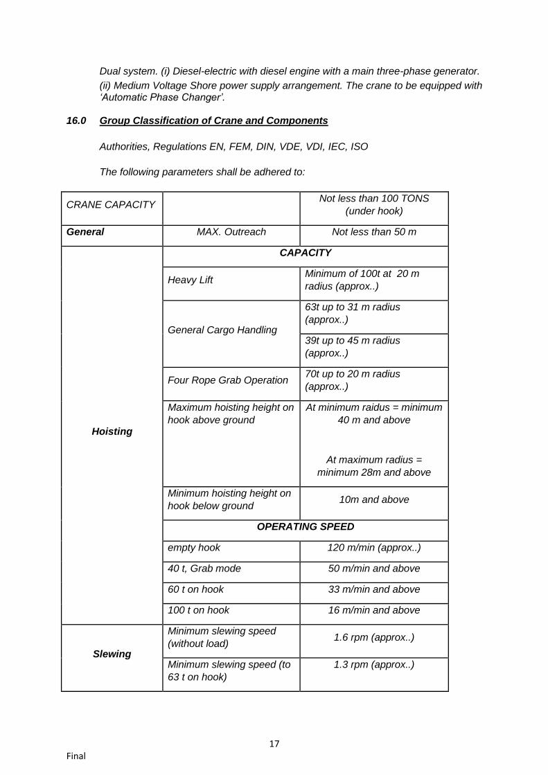
Dual system. (i) Diesel-electric with diesel engine with a main three-phase generator.
(ii) Medium voltage Shore power supply arrangement. The crane to be equipped with ‘Automatic Phase Changer’.
16.0 Group Classification of Crane and Components
Authorities, Regulations EN, FEM, DIN, VDE, VDI, IEC, ISO

7 Final
The following parameters shall be adhered to:
CRANE CAPACITY Not less than 140 tons under
hook
General MAX. Outreach Not less than 50 m
Hoisting
CAPACITY
Heavy Lift Minimum of 140t up to about
22 m radius
General Cargo Handling
Approx. 92t up to about 31 m
radius
Approx. 56t up to about 45 m
radius
Four Rope Grab Operation Approx. 72t up to about 27 m
radius
Maximum hoisting height on
hook above ground
At minimum radius =
minimum 51 m and above
At maximum radius =
minimum 30m and above
Minimum hoisting height on
hook below ground 15m and above
OPERATING SPEED
empty hook 120 m/min approx..
40 t, Grab mode approx.50 m/min and above
60 ton hook approx.33 m/min and above
144 ton hook Approx..14 m/min and above
Slewing
Minimum slewing speed
(without load) Approx.1.6 rpm
Minimum slewing speed (to
63 ton hook)
Approx. 1.3 rpm
Minimum tangential speed
at boom head (without load) Approx. 280m/min
Minimum tangential speed
at boom head (with load)
Approx. 186m/min
Slewing Range 360 deg
Luffing Maximum luffing speed approx. 90 m/min

8 Final
Average luffing speed (to 63
ton hook) 55m/min approx.
Travelling Long Travel 5 Km/h approx..
The crane and its machinery shall be designed according to the FEM 1.001 (Rules for the
Design of Hoisting Appliances) and shall have the following minimum classifications:
Crane Classification
Heavy lift operation 140t on hook A3
General cargo 65 t to 77t on hook A6
Four Rope operation, 63 t A8
Hoist
Heavy lift operation 140 ton hook M6
General cargo 90t on hook M8
Four rope operation, 75 t M8
Slewing Gear
All operation modes M7
Luffing Gear
All operation modes M7
Travelling gear
M4
Main Dimensions:
Outreach of the boom from crane centerline minimum 50 m or above
Height of boom pivot point above ground minimum 17 m
Height of eye level in tower cab minimum 24 m
The crane shall be designed to work safely and reliably under the following conditions:
Maximum gradient for travelling
- in direction of travel 6%
- perpendicular to direction of travel 2.5%
17.0 ENGINE:

9 Final
Appropriately sized direct injection, diesel engine. The Tenderer shall provide proof
that the engine shall provide adequate power and torque to the crane while
maintaining maximum fuel efficiency, preferably engines from the list indicated in
Annex, single heavy duty tropical fin & tube type radiator, engine coolant radiator and
transmission oil cooler. To have Automatic Engine shutdown at conditions that might
be deemed harmful to the engine e.g. high temperature and low engine oil pressure.
Air intake Pre-cleaner be designed to minimize dust intake. To have an on board &
External fault diagnostic facility.
All air intake filters to be fitted with sensors to feed PLC system with warning fault
messages when clogged. Machine house designed to be able to minimize dust
intake.
18.0 Drive System: Prime Mover - Diesel Engine, 4 stroke direct injection.
19.0 Undercarriage:
Adequate Number of axles suitable for the design uniform distributed load of the
quay shall be deployed.
All axles to be steerable.
All axles must have level compensation and fitted with differential equalizers.
A pair of twin pneumatic preferably tubeless tyres per axle.
Pneumatic impact wrench for use on nuts (with fast speed nut removal action if
possible) completed with hose attachments, accessories, box spanner fitted to a
suitable portable compressor.
Wide spacing of wheel axles for optimum stability during traveling
Automatic central greasing systems as standard Outriggers to be preferably fitted
with rollers
20.0 Steering: Should be capable of performing several steering modes i.e. driving in
longitudinal, diagonaldirection and also conventional steering or as standard.
21.0 Brakes: Luffing brake, Hoist brake, slew brake, parking / holding brake; Must be able
to stop automatically in case of power failure.
22.0 Tower: Welded pipe construction /box and beam construction of torsionally rigid
design with staircase leading to the tower cabin for access to the upper tower and jib
– heel. The tower should be well lit.
23.0 Boom: Fixed torsion resistant lattice construction with three main chords and
consisting of sections (fulcrum section and boom head.) Boom sections connected
with flanges. Boom luffing cylinders shall be protected from effects of climatic
conditions.
24.0 Ropes and sheaves: Self-lubricating, low twisting galvanized greased steel ropes
for hoisting, Large diameter rope sheaves with anti-friction bearings. Sheaves made
from special steel and the groove surface hardened to increase lifetime of sheave.
Hardness Number (Rockwell) to be mentioned by the manufacturer.

10 Final
25.0 Electrics: The electric equipment to comply with the relevant IEC and EN
standards. All wiring and cabling according to relevant DIN/VDE and IEC standards.
Load sensing and fault detection central computer
26.0 Propping system: Two integrated boxes housing four hydraulically operated
outrigger beams Manual and automatic operation. Even load distribution in rugged
terrain: pot holed yards, climb over rails and raised ground.
27.0 Testing: Crane to be fully erected rigged and load tested prior to handover.
28.0 Spares/tools etc.:
12000 running hours Spare parts shall be quoted according to the contractual bidding
forms and the buyer has the right to exclude/ reduce it , however a comprehensive list
of spares parts complete with prices shall be submitted with the tender.

11 Final
PREFERRED / INDICATIVE MANUFACTURERS FOR MAJOR COMPONENTS FOR THE
EQUIPMENTS
Generator Siemens
AVK
Stamford
Germany
Germany
UK

12 Final
The other brands maybe indicated by the tenderers. However, the acceptance of the same
will be confirmed by the tender holder prior to the end of technical evaluation.

13 Final
100 TONS MOBILE HARBOUR CRANES
1.0 This specification covers the design, manufacturing, inspection, testing and
commissioning at site of 100 Tons Mobile Harbour Cranes. IPGPL intends to procure 4 (four) nos. of Mobile Harbour Cranes of 100 Tons capacity for handling break bulk / dry bulk/ general / container cargo at Chabahar Port Multipurpose terminal. The following specifications are determined for 4 units of mobile harbor cranes of 100 Tons capacity, which are going to be installed in the Multi Purpose Terminal in Chabahar Port with environmental conditions stated below. The design and manufacture of these units should comply with the well known standards such as ISO, FEM, IEEE, ASME, IEC, JIS, EN, ECC, AWS, and SIS as applicable.
2.0 Environmental conditions
- Temperature range: 0 to +50°C
- Humidity: relative humidity up to 99%
- Height from sea level: 0
-Environment: Dusty, corroding and salty environment
- Permissible wind speed when the units are working: 72 km/h
3.0 Main Conditions
Suggested cranes should be designed for Iranian conditions. The cranes must work in the port conditions for continuous 20 hours per day and 7 days of the week. MHCs shall be of approx. 100 Tons capacity. The maximum permissible distributed load on the surface of the quay is 5 tons/m2. A separate winch for grabbing is to be provided. The radius of operation should be at least 50m.
Each crane must be equipped with the following: 3.1 Main telescopic spreader 40t to handle 20 ft and 40 ft ISO containers. 3.2 A Hook and Grab of minimum 24 cu.m capacity 3.3 Two units of special device for handling sheet rolls (coil hook) with 40 Tons
capacity.
4.0 Spreader& Grab The following equipment shall be supplied for common use of 2x140 T and 4x100 T Mobile Harbour cranes: 4.1 Two nos. of main telescopic spreader 40t to handle 20 ft and 40 ft ISO
containers. 4.2 Four nos. of Grab of minimum 24 cubic meter capacity 4.3 Two units of special device for handling sheet rolls (C-hook) with 40 ton
capacity.
5.0 Auxiliary systems:
The cranes must be equipped with the following systems:
- Fully Localized lubrication system for main parts that need lubrication separately.
- Wind speed alarm system
- All the sub-assemblies should have been manufactured by original and well –known companies.

14 Final
- Appropriate warning lights (rotary or flashing strobes) , motion alarms (horn, acoustic alarms), luminous air obstruction lights, emergency shutdowns and other necessary warning lights an alarms
- Adequate illumination for the working area, driver&operator cabins, machinery & electrical houses.
- Lightning protection system
- Fire detection and fire alarm system especially in electrical house, machinery house an Operator & Driver cabins.
- All maintenance platforms should have enough space for the repair of equipment and strong enough to support the weight of personnel and equipment together, with suitable access means
- The lighting system should be fitted on anti-vibration mounts to prevent failure, and according to existing standards/ dimensions of Iran.
- All stairs, walkways, platforms, bolts and nuts should be hot dip galvanized and stairs should have required safety.
- Vertical ladders should not be used for Access.
- One spare tyre with ring for each crane should be supplied.
- The manufacturer is bound to suggest 3 common sizes of tires for its crane (along with detail spec. of them including dia, width, layers, etc.)
- The machinery house should be equipped with proper filter for particles of the inlet air
- Emergency power supply (UPS) for warning and emergency lights.
- In all necessary locations of E-house, M-house and driver’s & operator’s cabins fire extinguishers should be installed.
- All of special and standard tools for maintenance & (specially those required for engine and its related components) must be supplied (related tables in questionnaire should be filled).
- Air-conditioning system and electric panel for M.H.Cs should be supplied via AC
power supply from the port mains (in parked position). The crane should have
provision for shore power supply arrangement and shall be operable in both
diesel and electric modes.
- Air compressor for adjusting the tyres pressure and its necessary equipment.
- Fuel tank should be equipped with drain valve and fuel indicator separately.
- Fueling must be done from the most suitable location of the crane with easiest
access.
6.0 Operator’s Cabin (Tower & Lower):
Each of two cabins must be equipped with the following:
- Air cooling (split type) in the cabin to adjust the temperature around 22ºc with
standard relative humidity.
- Monitor in the cabin to check the following places with camera (LCD is
preferable).
2 - Spreader (for fitting the spreader on the container)
2 - For travelling
- The cameras should be controllable (with all movements, focus & zoom ability)
from the operator’s cabin (with a good resolution at night and day).

15 Final
- Communication system including a public address system consisting a
microphone and amplifier together with speakers and 2 walkie-talkie handsets
with at least three VHF channels for each crane are needed.
- Maximum acceptable noise level in the cabs: 75 dBA
- Cabin windows should have wipers and fresh water spraying for cleaning the
window to clearly see the crane operation. Further, all the windows should be
able to be cleaned manually. All windows should be equipped with auto reset
curtains. Window glasses should be tinted safety glass with sunblinds.
- All of loading and operation indications should be displayed on the operator’s
display monitor.
- Tower cabin bottom glasses shall have guards.
7.0 Crane Control System
- Monitoring system besides of common abilities, should include suitable table and
electrical drawings for quick fault tracing
- The logic (Ladder) diagram of PLC control system should be submitted.
- Real time monitoring and recording of main movements (hoisting, slewing, luffing)
should be done with PLC.
- The electrical house should be equipped with air-conditioning system and filter for
inlet air.
- All joysticks must be equipped with dead man protection system.
8.0 Design Rules
Manufacturer should cover below items with FEM for its design: - Classification and loading on structures and mechanisms.
- Stress calculations in structures.
- Fatigue calculations and selection of mechanisms component.
- Stability and safety factor against movements by the wind.
- The vendor should foresee all the necessary conditions in its design and should
give the most compatible design for the mentioned ports environments.
- The vendor should carry out the final test.
9.0 Materials and structural steels
- All materials for load bearing structures should be weldable low carbon steel, and
free from defects and also have well-known certificates.
- All materials should conform to the most applicable specifications of DIN and FEM
standard.
10.0 Warning / Caution Instructions
In all the necessary positions and locations of the crane that caution instructions, are
needed, a note plate should be installed on that place, warning the personnel in Farsi
& English languages (corrosion resistant durable permanent plates).
11.0 Packing
- All equipment must be packed in a way that handling with forklift truck or crane is
possible.

16 Final
- If there is a risk of damage to apparatus during transportation, they shall be
disconnected and tagged. All the components shall then be securely packed.
- Equipment shall be adequately packed to withstand at least six months storage at
construction site prior to installation and the vendor shall recommend any
necessary procedures to be imposed during storage.
- Spare parts and tools to be packed separately and clearly marked “spare parts”
and “tools” respectively.
12.0 Standard Parts/Equipment Uniformity
- If possible, all the standard group parts / equipment shall be bought or procured
from a same sub-supplier and in one brand. For example all of bearings must be
bought from SKF or all of electrical motors shall be bought from (x) company.
- All of the equipment that are going to be bought, must be bought from the
manufacturers given in the maker list. (attached)
- Spare parts & tools shall be packed separately and clearly marked as “spare
parts” and “tools” respectively.
13.0 Documentation
The vendor should submit the below items in addition to the other stated documents:
1. General view of crane (2 Dimensional and 3 Dimensional with related
dimensions)
2. Electrical house equipment arrangement.
3. Machinery house equipment arrangement.
4. Catalogue with these information:
4-1) Loading diagram (lifting capacity chart)
4-2) Technical data (working speed: hoisting, slewing, luffing and travelling,…)
5. Operating user’s manual and maintenance manual clearly giving details of
preventive / breakdown maintenance, procedures for removing / reassembling of
various sub-assemblies for the main equipment as well as bought out items also
indicating spare parts numbers and ordering information should be written in
Farsi or English Languages in soft (CD) & hard (paper) version.
6. All equipment should have nameplates.
7. All of the Technical specification pages should be signed and stamped.
8. This technical specification (including 13 items) and its attached L.O.M are fixed
conditions and the manufacturer is bond to follow them exactly unless the buyer
otherwise requires.
14.0 Principal Duty
The Harbour Mobile crane shall have not less than 100 Tons lifting capacity under
hook at minimum radius, able to handle break bulk/ general cargo as well as fully
loaded containers from 62000 DWT size ships, along the berth and yards at the
Multipurpose Terminal of Port of Chabahar, Iran. The cranes’ outreach shall be not
less than 50m.
15.0 Power pack:
17 Final
Dual system. (i) Diesel-electric with diesel engine with a main three-phase generator.
(ii) Medium Voltage Shore power supply arrangement. The crane to be equipped with ‘Automatic Phase Changer’.
16.0 Group Classification of Crane and Components
Authorities, Regulations EN, FEM, DIN, VDE, VDI, IEC, ISO
The following parameters shall be adhered to:
CRANE CAPACITY Not less than 100 TONS
(under hook)
General MAX. Outreach Not less than 50 m
Hoisting
CAPACITY
Heavy Lift Minimum of 100t at 20 m
radius (approx..)
General Cargo Handling
63t up to 31 m radius
(approx..)
39t up to 45 m radius
(approx..)
Four Rope Grab Operation 70t up to 20 m radius
(approx..)
Maximum hoisting height on
hook above ground
At minimum raidus = minimum
40 m and above
At maximum radius =
minimum 28m and above
Minimum hoisting height on
hook below ground 10m and above
OPERATING SPEED
empty hook 120 m/min (approx..)
40 t, Grab mode 50 m/min and above
60 t on hook 33 m/min and above
100 t on hook 16 m/min and above
Slewing
Minimum slewing speed
(without load) 1.6 rpm (approx..)
Minimum slewing speed (to
63 t on hook)
1.3 rpm (approx..)

18 Final
Minimum tangential speed
at boom head (without load) 280m/min (approx..)
Minimum tangential speed
at boom head (with load)
186m/min (approx..)
Slewing Range 360 deg (approx..)
Luffing
Maximum luffing speed approx. 90 m/min
Average luffing speed (to 63
t on hook) 55m/min (approx..)
Travelling Long Travel 5 Km/h (approx..)
The crane and its machinery shall be designed according to the FEM 1.001 (Rules for the
Design of Hoisting Appliances) and shall have the following minimum classifications:
Crane Classification
Heavy lift operation 140t on hook A3
General cargo 65 t to 77t on hook A6
Four Rope operation, 63 t A8
Hoist
Heavy lift operation 140 ton hook M6
General cargo 90t on hook M8
Four rope operation, 75 t M8
Slewing Gear
All operation modes M7
Luffing Gear
All operation modes M7
Travelling gear
M4
Main Dimensions:
Outreach of the boom from crane centerline minimum 50 m
Height of boom pivot point above ground minimum 16.5 m

19 Final
Height of eye level in tower cab minimum 24.0 m
The crane shall be designed to work safely and reliably under the following conditions:
Maximum gradient for travelling
- in direction of travel 6%
- perpendicular to direction of travel 2.5%
The crane shall be designed to work safely and reliably under the following conditions:
Maximum gradient for travelling
- in direction of travel 6%
- perpendicular to direction of travel 2.5%
17.0 ENGINE:
Appropriately sized direct injection, (Normal engine instead of turbocharged to be
asked) diesel engine. The Tenderer shall provide proof that the engine shall provide
adequate power and torque to the crane while maintaining maximum fuel efficiency,
preferably engines from the list indicated in Annex…, single heavy duty tropical fin &
tube type radiator, engine coolant radiator and transmission oil cooler. To have
Automatic Engine shutdown at conditions that might be deemed harmful to the
engine e.g. high temperature and low engine oil pressure. Air intake Pre-cleaner be
designed to minimize dust intake. To have an on board & External fault diagnostic
facility.
All air intake filters to be fitted with sensors to feed PLC system with warning fault
messages when clogged. Machine house designed to be able to minimize dust
intake.
18.0 Drive System: Prime Mover - Diesel Engine, 4 stroke direct injection preferably
turbocharged.
19.0 Undercarriage:
Adequate Number of axles suitable for the design uniform distributed load of the
quay shall be deployed.
All axles to be steerable.
All axles must have level compensation and fitted with differential equalizers.
A pair of twin pneumatic preferably tubeless tyres per axle.
Pneumatic impact wrench for use on nuts (with fast speed nut removal action if
possible) completed with hose attachments, accessories, box spanner fitted to a
suitable portable compressor.
Wide spacing of wheel axles for optimum stability during traveling
Automatic central greasing systems as standard Outriggers to be preferably fitted
with rollers

20 Final
20.0 Steering: Should be capable of performing several steering modes i.e. driving in
longitudinal, diagonal direction and also conventional steering or as standard.
21.0 Brakes: Luffing brake, Hoist brake, slew brake, parking / holding brake; Must be able
to stop automatically in case of power failure.
22.0 Tower: Welded pipe construction /box and beam construction of torsionally rigid
design with staircase leading to the tower cabin for access to the upper tower and jib
– heel. Should be well lit.
23.0 Boom: Fixed torsion resistant lattice construction with three main chords and
consisting of sections (fulcrum section and boom head.) Boom sections connected
with flanges. Boom luffing cylinders shall be protected from effects of climatic
conditions.
24.0 Ropes and sheaves: Self-lubricating, low twisting galvanized greased steel ropes
for hoisting, Large diameter rope sheaves with anti-friction bearings. Sheaves made
from special steel and the groove surface hardened to increase lifetime of sheave..
Hardness Number (Rockwell) to be mentioned by the manufacturer
25.0 Electrics: The electric equipment to comply with the relevant IEC and EN
standards. All wiring and cabling according to relevant DIN/VDE and IEC standards.
Load sensing and fault detection central computer
26.0 Propping system: Two integrated boxes housing four hydraulically operated
outrigger beams Manual and automatic operation. Even load distribution in rugged
terrain: pot holed yards, climb over rails and raised ground.
27.0 Testing: Crane to be fully erected rigged and load tested prior to handover.

21 Final
PREFERRED / INDICATIVE MANUFACTURERS FOR MAJOR COMPONENTS FOR THE
EQUIPMENTS
The other brands maybe indicated by the tenderers. However, the acceptance of the same
will be confirmed by the tender holder prior to the end of technical evaluation.
Generator Siemens
AVK
Stamford
Germany
Germany
UK