Record Locator Service - Markle · Record Locator Service: ... via a clinical data exchange...
79
Record Locator Service: Technical Background from the Massachusetts Prototype Community THE CONNECTING FOR HEALTH COMMON FRAMEWORK T1 T2 T3 T4 T5 T6 P1 P2 P3 P4 P5 P6 P7 P8 P5 P6 P7 P8 M1 M2
Transcript of Record Locator Service - Markle · Record Locator Service: ... via a clinical data exchange...
Record Locator Service:Technical Background from the Massachusetts Prototype Community
THE CONNECTING FOR HEALTH COMMON FRAMEWORK
T1 T2 T3 T4 T5 T6
P1 P2 P3 P4 P5 P6 P7 P8P5 P6 P7 P8
M1 M2
CONNECTING FOR HEALTH COMMON FRAMEWORK
Record Locator Service –Technical Background from the
Massachusetts Prototype Community
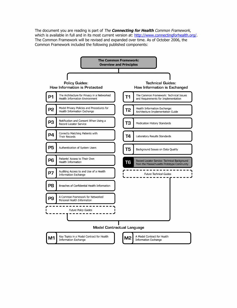
The document you are reading is part of The Connecting for Health Common Framework,which is available in full and in its most current version at: http://www.connectingforhealth.org/.The Common Framework will be revised and expanded over time. As of October 2006, theCommon Framework included the following published components:

Record Locator Service – Technical Background fromthe Massachusetts Prototype Community *
This document describes the early design process for the Record Locator Service (RLS)as implemented in Massachusetts, and is included here as background on the technicalconversation around the design of the Connecting for Health prototype. It is includedhere as a background guide to the issues surrounding the design of the RLS asconstructed in Massachusetts; as noted in “The Common Framework: Technical Issuesand Requirements for Implementation,” the placement of aggregation services can varybetween sub-network organizations (SNOs). In this document, aggregation takes placevia a clinical data exchange service; other architectural models are possible. In addition to the overview of the architectural design decisions included in“The Common Framework: Technical Issues and Requirements for Implementation,”the technical details surrounding message exchange in the current prototype aredocumented in the “Health Information Exchange: Architecture Implementation Guide.”
* Connecting for Health thanks Computer Sciences Corporation (CSC) for drafting this paper.
©2006, Markle Foundation
This work was originally published as part of The Connecting for Health: Resources for Implementing Private andSecure Health Information Exchange and is made available subject to the terms of a license (License) which may beviewed in its entirety at: http://www.connectingforhealth.org/license.html. You may make copies of this work; however,by copying or exercising any other rights to the work, you accept and agree to be bound by the terms of the License. Allcopies of this work must reproduce this copyright information and notice.
Architecture Document Page iii Version 1.1aRecord Locator Service 2005-11-22Confidential CSC, 2006
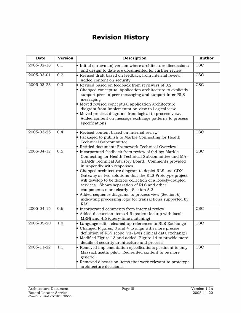
Revision History
Date Version Description Author
2005-02-18 0.1 Initial (strawman) version where architecture discussionsand design to date are documented for further review
CSC
2005-03-01 0.2 Revised draft based on feedback from internal review.Added content on security.
CSC
2005-03-23 0.3 Revised based on feedback from reviewers of 0.2 Changed conceptual application architecture to explicitly
support peer-to-peer messaging and support inter-RLSmessaging
Moved revised conceptual application architecturediagram from Implementation view to Logical view
Moved process diagrams from logical to process view.Added content on message exchange patterns to processspecifications
CSC
2005-03-25 0.4 Revised content based on internal review. Packaged to publish to Markle Connecting for Health
Technical Subcommittee Retitled document: Framework Technical Overview
CSC
2005-04-12 0.5 Incorporated feedback from review of 0.4 by: MarkleConnecting for Health Technical Subcommittee and MA-SHARE Technical Advisory Board. Comments providedin Appendix with responses.
Changed architecture diagram to depict RLS and CDXGateway as two solutions that the RLS Prototype projectwill develop to be flexible collection of a loosely-coupledservices. Shows separation of RLS and othercomponents more clearly. Section 5.2
Added sequence diagrams to process view (Section 6)indicating processing logic for transactions supported byRLS
CSC
2005-04-15 0.6 Incorporated comments from internal review Added discussion items 4.5 (patient lookup with local
MRN) and 4.6 (query-time matching)
CSC
2005-05-20 1.0 Language edits: cleaned up references to RLS Exchange Changed Figures: 3 and 4 to align with more precise
definition of RLS scope (vis-à-vis clinical data exchange) Modified Figure 13 and added Figure 14 to provide more
details of security architecture and process
CSC
2005-11-22 1.1 Removed implementation specifications pertinent to onlyMassachusetts pilot. Reoriented content to be moregeneric.
Removed discussion items that were relevant to prototypearchitecture decisions.
CSC
Architecture Document Page iv Version 1.1aRecord Locator Service 2005-11-22Confidential CSC, 2006
Table of Contents1 INTRODUCTION ........................................................................................................................... 7
1.1 P URPOSE...................................................................................................................................9 1.2 S COPE ......................................................................................................................................9 1.3 R EFERENCES ............................................................................................................................9 1.4 D OCUMENT O VERVIEW ........................................................................................................... 10 1.5 A RCHITECTURAL R EPRESENTATION.......................................................................................... 11
2 ARCHITECTURAL GOALS, PRINCIPLES AND CONSTRAINTS ............................................132.1 G OALS ................................................................................................................................... 13 2.2 P RINCIPLES ............................................................................................................................ 13
3 USE-CASE VIEW ........................................................................................................................173.1 RLS F UNCTIONS..................................................................................................................... 17 3.2 U SE C ASES ............................................................................................................................ 18 3.3 U SE -C ASE R EALIZATIONS ....................................................................................................... 21 3.4 S ECURITY , P ATIENT P RIVACY AND C ONSENT M ANAGEMENT ...................................................... 22
3.4.1 Identity management ....................................................................................................... 233.4.2 Confidentiality, Authentication, Integrity & Non-repudiation ......................................... 233.4.3 Patient Data Privacy ......................................................................................................... 233.4.4 Consent Management ...................................................................................................... 24
3.5 P ATIENTS R ECORDS L INKING AND M ATCHING........................................................................... 24
4 LOGICAL VIEW ..........................................................................................................................264.1 C ONCEPTUAL RLS-S ERVICES V IEW......................................................................................... 26 4.2 RLS A PPLICATION S ERVICES................................................................................................... 28 4.3 G ATEWAY S ERVICES ............................................................................................................... 30 4.4 RLS-B ASED N ETWORKS ......................................................................................................... 33 4.5 R EGIONAL AND N ATIONAL N ETWORK S UPPORT ......................................................................... 35
5 PROCESS VIEW .........................................................................................................................365.1 P ATIENT L OOKUP AND P EER TO P EER M EDICAL R ECORDS R ETRIEVAL....................................... 36 5.2 P ATIENT I NDEX P UBLISH ......................................................................................................... 37 5.3 C ENTRALLY M EDIATED M EDICAL R ECORDS R ETRIEVAL............................................................ 37 5.4 C ENTRAL M EDICAL R ECORDS A GGREGATION........................................................................... 38 5.5 S ECURITY P ROCESSES ............................................................................................................ 39 5.6 M ESSAGING P ATTERNS ........................................................................................................... 41
6 IMPLEMENTATION VIEW .........................................................................................................466.1 O VERVIEW ............................................................................................................................. 46 6.2 C OMPONENTS AND L AYERS ..................................................................................................... 47 6.3 I MPLEMENTATION T OPOLOGY O PTIONS..................................................................................... 52 6.4 S ECURITY M ODEL................................................................................................................... 54 6.5 I MPLEMENTATION P LATFORMS ................................................................................................. 55 6.6 I NTERCONNECTIVITY AND D ATA S TANDARDS............................................................................. 56
6.6.1 Messaging and Transport Standards .............................................................................. 576.6.2 Domain Data Standards .................................................................................................. 606.6.3 Comprehensive Standards List ........................................................................................ 61
7 DEPLOYMENT VIEW .................................................................................................................647.1 S ERVICES M ANAGEMENT ........................................................................................................ 66 7.2 S ECURITY S ERVICES............................................................................................................... 66
8 DATA VIEW ..............................................................................................................................678.1 CMPI I NFORMATION M ODEL................................................................................................... 67 8.2 L OGICAL D ATA M ODEL ........................................................................................................... 68
8.2.1 Identifier Attributes .......................................................................................................... 708.3 P HYSICAL D ATA M ODEL .......................................................................................................... 72
8.3.1 Data Quality Management ............................................................................................... 74
Architecture Document Page v Version 1.1aRecord Locator Service 2005-11-22Confidential CSC, 2006
8.3.2 Data Cache ....................................................................................................................... 74
9 DEFINITIONS, ACRONYMS, AND ABBREVIATIONS .............................................................75

Architecture Document Page vi Version 1.1aRecord Locator Service 2005-11-22Confidential CSC, 2006
List of FiguresFigure 1: Architecture views and their contents................................................................. 12Figure 2: RLS Long term Concept of Operations ................................................................ 18Figure 3: RLS Prototype Use Case Diagram........................................................................ 19Figure 4 Lookup Patient and Publish Patient Index Activity Diagrams............................ 22Figure 5 RLS Conceptual Architecture of Operation.......................................................... 26Figure 6 Service Oriented Interoperation ............................................................................ 27Figure 7: RLS Distribution of Components......................................................................... 31Figure 8: Gateway based interaction in a health information network............................ 33Figure 9 Network of clinical systems communicating peer-to-peer .................................. 34Figure 10 Network of RLS-based networks (potentially used by RHIO) ........................... 35Figure 11: Patient Lookup with RLS and Medical Records Retrieval through CDX
Gateways......................................................................................................................... 36Figure 12 Patient Publish into RLS Patient Index.............................................................. 37Figure 13 Centrally Mediated Patient Lookup and Record Retrieval (hosted gateway)... 38Figure 14 Patient Lookup and Records Retrieval -- In One Step ...................................... 38Figure 15 RLS authentication service.................................................................................. 40Figure 16: Authentication Mechanisms for Patient Lookup and Medical Records
Retrieval .......................................................................................................................... 41Figure 17 Patient lookup sequence diagram....................................................................... 44Figure 18 Publish patient index sequence diagram........................................................... 45Figure 19 RLS and CDX Gateway components and sample (prototype) implementation
platforms ......................................................................................................................... 48Figure 20 Web services stack ............................................................................................... 58Figure 21 WS-I Basic Profile Web Services stack ............................................................... 59Figure 22 Interoperability Network Layers.......................................................................... 61Figure 23 Potential Production Deployment View of RLS................................................. 65Figure 24 Information Model View....................................................................................... 67Figure 25 Logical Data Model............................................................................................... 69Figure 26 Patient Identifier Composition in CMPI.............................................................. 73
List of TablesTable 1 List of Architecturally Significant Use Cases ......................................................... 20Table 2 List of Messaging Interactions supported by RLS Prototype ................................ 42Table 3 CDX Gateway Service / Components Description ................................................ 49Table 4 RLS Components Description ................................................................................. 51Table 6 Prototype Platform and Options ............................................................................. 55

Architecture Document Page 7 Version 1.1aRecord Locator Service 2005-11-22Confidential CSC, 2006
1 Introduction
The Record Locator Service (RLS) is envisioned as the keyinfrastructure component of the ‘Common Framework’, whichMarkle Foundation Connecting for Health (CfH)† has proposed tofacilitate healthcare information networks in the USA. The commonframework is a set of standards, policies, and methodologiesintended to ensure secure and reliable connectivity betweenhealthcare systems and enterprises.
The common framework includes the essential set of standards andpolicies that would allow healthcare information networks tointeroperate with each other. This would enable communities andregional networks to connect and incrementally grow into anational healthcare information network, as a “network ofnetworks”.
Building a national network through internetworking multipleregional and local health information networks implies a naturalbias towards decentralization. A centralized national patientregistry or clinical data repository is not considered a realisticobjective. Adoption of common architecture and protocols acrossthe networks and sub-networks would, similarly, suggestdecentralization in sub-networks, with data stored in separatelocations to be accessed when needed. Leaving patient data wherethey are now, in the healthcare enterprises’ clinical data sourcesalso provides for appropriate patient data privacy safeguards andclear accountability for medical data ownership/stewardship.
This does not preclude sub-networks based on a regional datarepository or a community master patient index. As long as thenetworks support the principles and protocols of the commonframework, they would be capable of interoperation with othernetworks. Smaller participants may choose to use data aggregatorsto expose their clinical data securely and reliably. As the CfHRoadmap states, “Because many providers will not be able orperhaps willing to provide the levels of service required toparticipate in a federation, they may have to contract with businessassociates (in the HIPAA sense) to store their data in a repositorythat will sustain these service levels.”‡
The common framework that underlies the decentralized healthcareinformation network is expected to need a small set of criticaltechnical infrastructure components to support interoperability.The RLS is one of them.
† http://www.connectingforhealth.org‡ [CfH2004]

Architecture Document Page 8 Version 1.1aRecord Locator Service 2005-11-22Confidential CSC, 2006
The RLS provides authorized users of a regional health informationnetwork with pointers to the location of patient health informationacross the network nodes, i.e. the clinical data sources. This wouldenable users to access and integrate patient healthcare informationfrom the distributed sources without national patient identifiers orcentralized databases. Such an integrated view of patient clinicaldata would help achieve the CfH vision of improved patient safetyand quality of care, and reduced costs of healthcare delivery.
Massachusetts SHARE (Simplifying Healthcare Among RegionalEntities)§, a regional collaborative initiative operated by theMassachusetts Health Data Consortium, seeks to fosterimprovements in community clinical connectivity, allowingappropriate sharing of inter-organizational healthcare data amongthe various participants in the healthcare system – includingpatients, doctors and other practitioners, hospitals, government,insurers, HMOs and other payers. MA-SHARE promotes the inter-organizational exchange of healthcare data using informationtechnology, standards and administrative simplification, in order tomake accurate clinical health information available whereverneeded in an efficient, cost-effective and safe manner.
MA-SHARE’s vision includes the goal of building a utility servicethat would enable member organizations to hook up to the regionalhealthcare network (or “grid”) simply and cost-effectively. The RLSarchitecture advances the design of such a utility service thatwould connect the healthcare systems in a community securelyover the Internet.
This document describes the proposed architecture of the RLS, andprovides an overview of the technical components of the commonframework. The RLS prototype project tests the architecturepresented here and demonstrates the viability of direct peer-to-peerinteroperability of disparate electronic health record (EHR) systemsthat are the ultimate source of clinical data in the network. Thisdocument serves as the primary record of all architectural designdecisions made in the course of developing the RLS prototype.
§ http://www.mahealthdata.org/ma-share/index.html

Architecture Document Page 9 Version 1.1aRecord Locator Service 2005-11-22Confidential CSC, 2006
1.1 Purpose
The Framework Technical Overview defines and describes the basicfunctional components that make up the RLS, and the interfacesbetween these components. The document presents the RLSarchitecture using a number of different architectural views todepict different aspects of the system, and outlines the data andtransport standards used in accessing the services offered by RLS.RLS plays a critical role in the healthcare interoperability commonframework, and the RLS service architecture is aligned with theclinical data exchange processes that the common framework alsosupports. This document also conveys the architecturallysignificant trade-offs and decisions which have been made indesigning the system and the network.
Business stakeholders may use this document to validate thefunctionality of RLS in the patient care setting, and to gainunderstanding of the major services provided by the system. TheRLS architecture is intended to serve as a reference for systemdesigners to guide the detailed design of the system during theelaboration and construction phases of a system developmentproject.
1.2 Scope
The Framework Technical Overview provides details of the technicalarchitecture of the Record Locator Service prototype and outlinesthe strategy to meet the architectural (longer-term) requirements forthe RLS as defined in the Markle Foundation Connecting for HealthCommon Framework Record Locator Service ReferenceImplementation Statement of Work**.
Technical architecture covers the domains of data, application andtechnology infrastructure. While technical architecture needs to bedeveloped in the context of the organizational and business processarchitecture, these domains are out of scope of FrameworkTechnical Overview. This document uses prior work by CfH todefine the RLS business context and defines the technicalarchitecture to fulfill the use case requirements thereof. The otherimportant component of the common framework is the policyframework produced by the CfH Policy Sub-committee. Thiselement of the framework was under development during theproduction of this technical architecture document; policy basedrequirements have been considered where available.
1.3 References[CfH2004] Achieving Electronic Connectivity in Healthcare, A Preliminary
Roadmap from the Nation’s Public and Private Sector HealthcareLeaders, Connecting for Health, Markle Foundation, July 2004.
** [CfH2005a]

Architecture Document Page 10 Version 1.1aRecord Locator Service 2005-11-22Confidential CSC, 2006
[CfH2004a] Accurately Linking Information for Healthcare Quality andSafety, Connecting for Health, Markle Foundation, Draft FinalReport by Working Group on Accurately Linking Information forHealthcare Quality and Safety, September 2004.
[CfH2004b] Connecting for Health Reference Implementation Launch, InCollaboration with the RWJF and Foundation for eHealth InitiativeConfidential Draft Document for Discussion Only October 29,2004
[CfH2005] Linking Healthcare Information: Proposed Methods for ImprovingCare and Protecting Privacy, Carol Diamond, Connecting forHealth, Markle Foundation, HIMSS 2005
[CfH2005a] Markle Foundation Connecting for Health Common FrameworkRecord Locator Service Reference Implementation Statement ofWork, CSC, February 2005.
[CfH2005b] Linking Healthcare Information: Proposed Methods for ImprovingCare and Protecting Privacy, Working Group on Accurately LinkingInformation for Healthcare Quality and Safety, February 2005.
[MAeHC2004a] Expanding the Use of Electronic Health Records andEstablishing a Regional Health Information Infrastructure inMassachusetts, Request for Applications, December 6, 2004, TheMassachusetts eHealth Collaborative.
[MHDC2004a] Analysis of Approach to Uniquely Identifying Patients inMassachusetts, Massachusetts Health Data Consortium, Inc.2004
1.4 Document Overview
The Framework Technical Overview document provides a high leveloverview of the software artifacts that make up the RLS. Thedocument lays out the key business processes that the RLS isintended to support, a logical view of the components and theirbehavior, and the proposed deployment of the software oncompletion of development. The remainder of this section definesthe concept of software architecture and describes the notationused to document it.
Section 2 defines the goals, principles, and constraints of the RLSarchitecture.
Section 3 lists the subset of use cases and scenarios that impactthe architectural design of the system. Use cases represent themajor business or functional requirements that the software isexpected to meet.
Section 4 shows the decomposition of the solution into a set oflogical elements, i.e., classes, subsystems, packages, andcollaborations.
Section 5 presents the process structure of the system. Theprocess view maps the logical view elements to the processes andthreads in the solution.

Architecture Document Page 11 Version 1.1aRecord Locator Service 2005-11-22Confidential CSC, 2006
Section 6 presents the implementation view of the system, i.e. thedecomposition of the system into layers and packages. Alternativeimplementation models are presented that may be appropriate forspecific scenarios.
Section 7 presents the deployment view, which maps the prototypecomponents to a set of hardware and network nodes on which theyexecute. Given that this is an architecture document
Section 8 provides a view of the persistent data storage of thesystem to the extent that this is significant in a network withminimal central data storage.
A glossary of key terms, abbreviations, and acronyms used in thisdocument is provided in Section 9.
1.5 Architectural Representation
The RLS software architecture defines the overall structure of thesystem in terms of the behavior of its components. Softwarearchitecture needs to be viewed from multiple perspectives and atdifferent levels of abstraction to gain a full understanding of thesystem. In this document, the following architectural views areused:
¶ Use case view: outlines the functional requirements of RLS from anend-users perspective.
¶ Logical view: where the major subsystems and components of RLS areidentified and a conceptual view of their working provided.
¶ Process view: describes the runtime behavior of RLS components inmeeting key functional requirements.
¶ Implementation view: provides the organization of the RLS softwareartifacts in terms of layering and packaging.
¶ Deployment view: describes how the various RLS software packagesand runtime components are deployed on hardware and networknodes.
Architecture Document Page 12 Version 1.1aRecord Locator Service 2005-11-22Confidential CSC, 2006
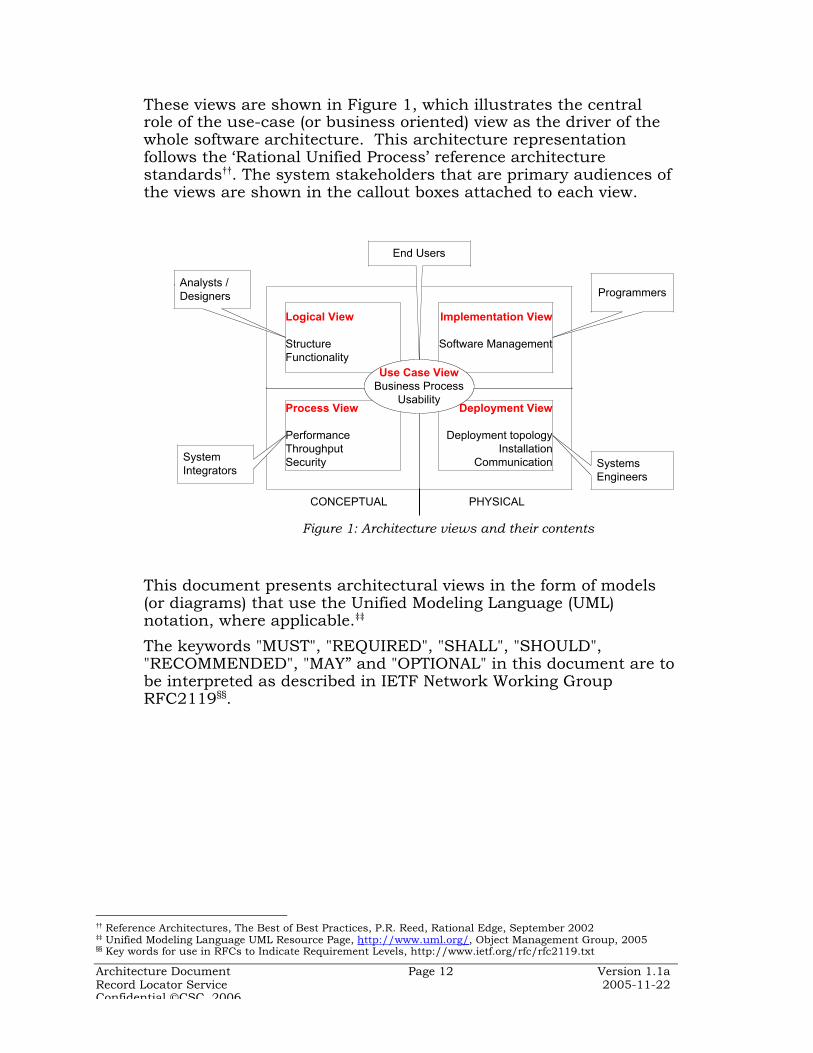
These views are shown in Figure 1, which illustrates the centralrole of the use-case (or business oriented) view as the driver of thewhole software architecture. This architecture representationfollows the ‘Rational Unified Process’ reference architecturestandards††. The system stakeholders that are primary audiences ofthe views are shown in the callout boxes attached to each view.
This document presents architectural views in the form of models(or diagrams) that use the Unified Modeling Language (UML)notation, where applicable.‡‡
The keywords "MUST", "REQUIRED", "SHALL", "SHOULD","RECOMMENDED", "MAY” and "OPTIONAL" in this document are tobe interpreted as described in IETF Network Working GroupRFC2119§§.
†† Reference Architectures, The Best of Best Practices, P.R. Reed, Rational Edge, September 2002‡‡ Unified Modeling Language UML Resource Page, http://www.uml.org/ , Object Management Group, 2005§§ Key words for use in RFCs to Indicate Requirement Levels, http://www.ietf.org/rfc/rfc2119.txt
Implementation View
Software Management
Deployment View
Deployment topologyInstallation
Communication
Process View
PerformanceThroughputSecurity
Logical View
StructureFunctionality
Use Case ViewBusiness Process
Usability
PHYSICALCONCEPTUAL
SystemIntegrators
Analysts /Designers Programmers
SystemsEngineers
End Users
Figure 1: Architecture views and their contents

Architecture Document Page 13 Version 1.1aRecord Locator Service 2005-11-22Confidential CSC, 2006
2 Architectural Goals, Principles and Constraints
Architecture best practice calls for the definition of commonprinciples at the outset to serve as a consistent basis for designdecisions to be made downstream. Information Technology (IT)architectural principles define the fundamental rules andguidelines for the development and deployment of IT resources andassets. They reflect a level of consensus among the variousstakeholders of the system, and form the basis for making coherentand consistent architecture and design decisions.
Architectural principles are, therefore, high level statements thatgovern the system architecture development process. Based on theCfH charter and the longer term MA-SHARE vision, the followingRLS architecture goals, principles and constraints are proposed.
2.1 Goals
The guiding vision for RLS is that to provide directory and registryservices for a regional health information network which supportsthe interoperability between disparate healthcare informationsystems in a community, reducing healthcare delivery costs andimproving quality of care as well as patient safety.
CfH defines the primary objective of the Reference Implementationof the Record Locator Service as: to validate a set of standards thatwould, if implemented across communities, enable healthinformation exchange within and between communities regardlessof the hardware and software platforms used***. Such standardsand profiles are part of an interoperability architectural framework,which has been referred to as the ‘Common Framework’ by CfH.The technical standards would align with the other components ofthe common framework, which includes policies and methods.
The RLS is assumed to operate under the auspices of a RegionalHealth Information Organization (RHIO) that coordinates thevarious healthcare enterprises in the region (or community). RHIOsserve as distributed hubs of a prospective National HealthInformation Network.
2.2 Principles
¶ Patient privacy protection: Clinical data sharing shall be subject tovery stringent privacy and security constraints. All access to patienthealth data must be secured through strong authentication andauthorization, comprehensively auditable, and subject to sanctions forpolicy violations.
*** CfH 2004b

Architecture Document Page 14 Version 1.1aRecord Locator Service 2005-11-22Confidential CSC, 2006
Secure and confidential treatment of patient information shall be afundamental property of all technological and process artifactspertaining to RLS. This tenet shall be built into the RLSarchitecture.
Given the varying privacy regulations existing across states in theUS, RLS should support the most stringent protection of healthinformation, including the requirement of explicit patient consentfor disclosure of data.
In some cases varying levels of protection are required for differentcategories of clinical information pertaining to conditions such asmental illness and AIDS.
¶ Decentralized and federated architectures: Respecting the mandatefor a de-centralized, federated architecture of healthcare informationnetworks, RLS shall employ federated information architectureensuring that each node in a RLS connected network retain‘informational sovereignty”†††. A central data repository of aggregated patient healthcare data
creates a large target and poses an unacceptable privacy risk in thecurrent political and network environment.
A ‘National Health Identifier’ for each person is impractical in thedecentralized world of healthcare in the USA. Instead, RLS wouldsupport linking of health records that remain distributed andmanaged at their points of origin.
Data distribution should be biased to local control of clinicalrecords and access to them. Personal health information shouldcontinue to reside where they do now, primarily with hospitals andhealthcare providers. Decisions about disclosure of suchinformation should be made at the source of the data, with patientconsent if so required.
Users shall be authenticated and authorized to access patientinformation at the “edges” as well, obviating the need forcentralized identity management of all authorized users.
¶ Open Standards: All solutions / components shall be based on openstandards and not be dependent on any proprietary technologies.While standards in themselves do not guarantee interoperability,emphasizing standards across the network communication stackhelps mitigate most of the common problems that have impededinformation sharing in the past. HL7 (version 2.x or 3.0) and NCPDP SCRIPT, the de facto industry
messaging standards for general healthcare and prescription datarespectively, should be used where applicable. The HL7 ReferenceInformation Model offers a ready set of data standards that providethe semantic interoperability underpinning for HL7 messagingstandards.
XML 1.0 is the data message notation standard for inter-application data communication and shall be the default messageserialization format.
New or private network services shall not be required: the solutionshould be based on secure data transport over the public Internet.
††† CfH2004a
Architecture Document Page 15 Version 1.1aRecord Locator Service 2005-11-22Confidential CSC, 2006
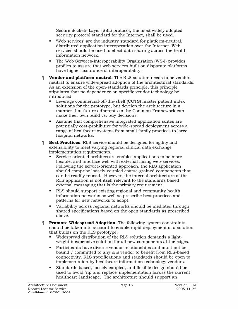
Secure Sockets Layer (SSL) protocol, the most widely adoptedsecurity protocol standard for the Internet, shall be used.
‘Web services’ are the industry standard for platform-neutral,distributed application interoperation over the Internet. Webservices should be used to effect data sharing across the healthinformation network.
The Web Services-Interoperability Organization (WS-I) providesprofiles to assure that web services built on disparate platformshave higher assurance of interoperability.
¶ Vendor and platform neutral: The RLS solution needs to be vendor-neutral to ensure wide-spread adoption of the architectural standards.As an extension of the open-standards principle, this principlestipulates that no dependence on specific vendor technology beintroduced. Leverage commercial-off-the-shelf (COTS) master patient index
solutions for the prototype, but develop the architecture in amanner that future adherents to the Common Framework canmake their own build vs. buy decisions.
Assume that comprehensive integrated application suites arepotentially cost-prohibitive for wide-spread deployment across arange of healthcare systems from small family practices to largehospital networks.
¶ Best Practices: RLS service should be designed for agility andextensibility to meet varying regional clinical data exchangeimplementation requirements. Service-oriented architecture enables applications to be more
flexible, and interface well with external facing web-services.Following the service-oriented approach, the RLS applicationshould comprise loosely-coupled coarse-grained components thatcan be readily reused. However, the internal architecture of theRLS application is not itself relevant to the standards basedexternal messaging that is the primary requirement.
RLS should support existing regional and community healthinformation networks as well as prescribe best practices andpatterns for new networks to adopt.
Variability across regional networks should be mediated throughshared specifications based on the open standards as prescribedabove.
¶ Promote Widespread Adoption: The following system constraintsshould be taken into account to enable rapid deployment of a solutionthat builds on the RLS prototype: Widespread distribution of the RLS solution demands a light-
weight inexpensive solution for all new components at the edges. Participants have diverse vendor relationships and must not be
bound / committed to any one vendor to benefit from RLS-basedconnectivity. RLS specifications and standards should be open toimplementation by healthcare information technology vendors.
Standards based, loosely coupled, and flexible design should beused to avoid ‘rip and replace’ implementation across the currenthealthcare landscape. The architecture should support an

Architecture Document Page 16 Version 1.1aRecord Locator Service 2005-11-22Confidential CSC, 2006
incremental migration from current technology to future standardsbased interoperation.
Participants in health information networks have significantinvestments in EHR and personal health record (PHR) applications.RLS should support connectivity between them, with incrementalmigration paths that call for moderate incremental investment.
¶ Flexible Implementation Models: The RLS architecture shouldenable top-down and bottom-up implementation strategies, favoringlocal network infrastructure development to promote widespreadusage and national interoperability models to promote inter-regionalinformation sharing. From a technological standpoint, the RLSarchitecture should support three implementation models: Gateway: Physically deployable service that may be integrated into
RLS subscriber enterprise IT environment, and allowing secureaccess to RLS.
Application Programming Interface specifications: Allow solutionproviders (package vendors and custom development shops) toimplement RLS components independently on platforms of theirchoice without detracting from interoperability.
Hosted: All RLS services are hosted for subscribers unable oruninterested in owning and operating the RLS accessinfrastructure. Such a solution would be an attractive option forsmaller physician practices and institutions that prefer tooutsource their information technology services.
Architecture Document Page 17 Version 1.1aRecord Locator Service 2005-11-22Confidential CSC, 2006
3 Use-Case View
The RLS system architecture is primarily driven by the functionalrequirements of the health information network. Functionalrequirements are captured in use case models or requirementsdefinition documents, as well as vision and mission statementsdescribing the longer term strategy. In addition, architectures havetechnology drivers and need to be cognizant of constraints of theinformation processing environment in which the system operatesand the technology platforms used to implement the architecture.
The Use Case view represents the end users view of the system, andprovides insight into the business goals of the system. Use casesrepresent the interactions that take place between the system andits users. Use case diagrams provide a schematic view of the end-user requirements that the system expects to satisfy. Use cases donot capture all the functionality of a system, only the users’activities with respect to the system. Also note that use casespecification diagrams need to be supplemented by textualdescriptions that provide details of the requirements, which are notprovided in this document.
3.1 RLS Functions
RLS is intended to serve as a key infrastructure element in aregional health information network. RLS primarily maintains anindex of pointers to the network location of patient information, butnot the personal health information itself. The index of pointers isakin to a ‘master patient index’ as deployed in integrated healthcaredelivery networks with multiple independent clinical systemsmaintaining patient records.
RLS serves as a coordinating service that obviates the need for anational health identifier, by linking diverse patient records acrossdistributed clinical data sources through probabilistic demographicmatching techniques. Such a service can facilitate a federation ofdiverse clinical data sources to enable a consolidated view of apatient’s electronic health care records. The clinical datanomenclature includes a range of information from medical recordsin provider systems, dispensed drug information at pharmacysystems, to administrative and financial information in payersystems.
Various institutional models have been discussed for ownershipand operation of an RLS. In the current environment, the logicalorganizational framework for an RLS would seem to be a regionalhealth information organization (RHIO). RHIOs are considered keyelements of the strategy for constructing an interconnected and

Architecture Document Page 18 Version 1.1aRecord Locator Service 2005-11-22Confidential CSC, 2006
interoperable network of networks that forms the national healthinformation network (NHIN).
Massachusetts SHARE (Simplifying Healthcare Among RegionalEntities), a regional collaborative initiative operated by theMassachusetts Health Data Consortium, may play the role of aRHIO. One of MA-SHARE’s goals is to create a sustainablecommunity utility for clinical connectivity and data exchange. Thefuture extension of RLS to serve as such a utility is a considerationin its architecture.
While RLS primarily supports individual caregivers by facilitatingaccess to aggregated patient information, it may facilitateinformation sharing across other authorized stakeholders as well,including the patient. A longer term ‘concept of operations’ view ofRLS is shown in Figure 2.
3.2 Use Cases
The architecturally significant use cases of RLS are shown in Figure3. The primary end user function of RLS is to provide healthcarepractitioners with pointers to clinical data stored at distributednetwork nodes. To establish context it useful to understand thecomplete usage scenario from a healthcare practitioner’sperspective, which would include subsequent retrieval of patientrecords. Patient records retrieval is not an RLS function, and is
Secure Internet
Hospitals / IDNsIntegrated Delivery Network
Academic Medical Center
Community Hospital
Community Health Center /
Clinic
Specialty Hospital /
Emergency Dept .
Payers
MassHealth (Medicaid )
Medicare (CMS )
Commercial Health Plan
Behavioral Health , etc .
State / Public Health Entities
Department of Public
HealthState Labs
Commercial Third Parties
Application Service Provider
Clearinghouse/ Aggregator
Labs & Diagnostic Centers
Commercial Reference
Lab
Diagnostic Imaging Center
Pharmacies
Pharmacy Benefit
Manager
Retail Drug Store
Patients
Practitioners / Physicians
Community Record Locator Service
Hosted and Distributed Integration
Services
Help Desk & Operations
Support
Community Master
Patient Index Services
Network Directory &
Registry Services
Figure 2: RLS Long term Concept of Operations

Architecture Document Page 19 Version 1.1aRecord Locator Service 2005-11-22Confidential CSC, 2006
shown as a separate ‘clinical data exchange’ service in the use casediagram.
Actors are entities (both human and system) that interact directlywith the RLS. RLS actors include:
1. Healthcare practitioners: Individual care providers who havebeen assigned rights to access a patient’s clinical record.This category includes providers, payers, diagnostic servicesetc., as well as the patient.
2. Clinical Data Source: The information systems in use by ahealthcare provider or payer to maintain patient relatedinformation. Data sources encompass systems at physicianoffices, hospitals, laboratories, imaging centers, pharmaciesand other healthcare service entities.
3. RLS Administrator: Persons (or entities) authorized toadminister the Record Locator Service and the community
Record Locator Service
Lookup PatientRecord Locations
Healthcare Practioner
Select from MatchingPatient Index List
RLS Administrator
Manage ParticipantIdentities / Addresses
Monitor / AuditMessage Logs
Clinical Data Source
Publish PatientIndex
Maintain PatientIndex
Clinical Data Exchange
Request PatientMedical Records
Provide PatientMedical Records
View AggregatedClinical Acts Records
Figure 3: RLS Prototype Use Case Diagram

Architecture Document Page 20 Version 1.1aRecord Locator Service 2005-11-22Confidential CSC, 2006
patient index as may be required. Note: this role is expectedto be progressively automated as the RLS implementationmatures.
Note that the core RLS function is only to locate patient records.This essentially implies providing indexing services for distributedclinical data sources, which publish patient registry events into theRLS. This separation of services is a key aspect of the CfH strategywhich seeks to decouple the standards and policies relating toseparate functions of the network‡‡‡.
The following use cases are architecturally significant to the RLS, inthat they exercise critical aspects of the system architecture:
Table 1 List of Architecturally Significant Use Cases
Name DescriptionLookup patients On entry of search criteria by authenticated and authorized
users, system shall retrieve a list of patients matching thesearch criteria entered.
System shall return the list of patient records with ‘locations’(or web addresses) where these records may be accessed
Publish patientindex
On entry of new patient records in the clinical data source(e.g. after a registration or ADT event), or upon changes toexisting patient records, the clinical data source node shalltransmit a set of demographic attributes and a pointer to thepatient record (typically in the form of a Medical RecordNumber) to the patient index maintained centrally at the RLS(the community Master Patient Index, or CMPI)
The RLS acknowledges receipt of the changed recordinformation.
Authenticateauthorized users
RLS users are authenticated as authorized network users bythe clinical system to which the user is affiliated.
Communicatesecurely
RLS and the clinical system communicate securely over theinternet.
Senders and receivers of messages are mutuallyauthenticated before exchange of messages; messageconfidentiality and integrity are assured; and message non-repudiation is enabled for both sender and receiver
Log messages All messages are logged with name of user / organizationinitiating the operation. Logs can be audited for informationon all access to RLS patient index
‡‡‡ CfH2005b
Architecture Document Page 21 Version 1.1aRecord Locator Service 2005-11-22Confidential CSC, 2006
3.3 Use-Case Realizations
The patient lookup and patient publish use cases are both realizedthrough messages sent securely from nodes in the healthinformation network to the RLS requesting lookup and publishservices respectively. The ‘lookup patient’ and ‘publish patientindex’ use cases are realized in the manner shown in the activitydiagram in Figure 4.
The swimlanes in the activity diagrams correspond to the actorsshown in the use case diagram. Healthcare practitioners andclinical data sources are roles played by entities such as hospitals,physician practices, diagnostic services, payers, public healthagencies etc. Thus, a provider system at a network node could playthe role of a clinical data source, and also be the channel throughwhich healthcare practitioners access the RLS.
While the core functionality of RLS is to support publishing into,and searching the CMPI, the RLS-based network would requireinformation processing in each of the nodes interacting with thepatient index to support secure, reliable and standards basedcommunication between them. This communication function is thecore of the common framework that enables the various networknodes to exchange information with the RLS and with each other.The communication functionality at these nodes share manycommon processing capabilities which may be encapsulated into acommon technology artifact as shown in Section 4.

Architecture Document Page 22 Version 1.1aRecord Locator Service 2005-11-22Confidential CSC, 2006
Clinical Data SourceRecord Locator ServiceHealthcare Practitioner
CommunicatePatient Lookup
Request Message
Search CMPI for Patients Matching Criteria Entered
Insert / Update CMPI
{Data queries and updates across enterprise (trust domain) boundaries are subject to authentication and authorization checks of principals (users and systems)}
Communicate PatientPublish Message w.
Demographics & MRN
Display Patient RecordLocations to pick from
Log Access toPatient Index
Records in CMPI
{Patient R
egistr at ion Ev ent : }
Authenticate& Verify Authoriz-
ation of User
Log PatientLookup Operation
CommunicatePatient Record
Locations
Log PatientPublish Operation
Figure 4 Lookup Patient and Publish Patient Index Activity Diagrams
Other functional aspects that influence the RLS architectureinclude:
3.4 Security, Patient Privacy and Consent Management
Protection of patient privacy is a legal and regulatory requirementthat is realized through system security as well as policiesimplemented by the RLS and the various participants in thehealthcare information network. Patient and healthcarepractitioner trust in the security and privacy protection features ofthe RLS-based network is a critical pre-requisite to its success.
Privacy protection is based on restricting network access to thedata to only authorized personnel, monitoring all access to patientdata to audit the operational use of the network, and implementingarchitectural safeguards to manage the risk of accidental ormalicious spillage of data in the course of network operation.

Architecture Document Page 23 Version 1.1aRecord Locator Service 2005-11-22Confidential CSC, 2006
3.4.1 Identity management
The RLS is intended for use by large networks of healthcareenterprises, each of which may have large user end userpopulations. RLS must not be required to manage the networkidentities of all individual users. End users (healthcarepractitioners) are authenticated by the enterprise to which they areaffiliated and referred to RLS as authenticated principals. Identitymanagement is a local function. Patients who use hospital / IDNpatient web sites are referred to RLS as authenticated principals bythe clinical systems at the hospital / IDN. RLS and all participatingentities have the ability to mutually authenticate each other beforeexchanging data.
3.4.2 Confidentiality, Authentication, Integrity & Non-repudiation
The RLS network architecture uses the following high level securityrequirements in implementing messaging as well as applicationdata management§§§:
¶ Confidentiality: Information shall only be disclosed to authorized userswho need it for healthcare treatment, payment, or operations.
¶ Authentication: Receivers of requests for information shall be able toverify the identity of the requester. A network participant shall not beable to masquerade as anybody else.
¶ Integrity: Communication between network entities shall be protectedagainst unauthorized alteration, and all alterations shall be logged.Receiver shall be able to verify that the message has not been altered.
¶ Non-repudiation: Transactions cannot be unilaterally revoked oraltered by either party. A sender cannot falsely deny sending amessage and a receiver cannot falsely deny receipt of a message.
3.4.3 Patient Data Privacy
The health information network is architected on the presumptionthat data privacy is easier to protect locally, i.e. on the edges of thenetwork where data are stored. Release of information from theclinical data source to healthcare practitioners is governed bypolicies established and maintained by the data source.
RLS, being a directory of patient record locations, is itself a sourceof protected health information. RLS shall publish and maintain aclear policy governing discovery of patient information in thedirectory. The specific rules governing sharing of RLS directoryinformation pertaining to individual patients are created by thepatient and provider at the time of the encounter andcommunicated to the RLS along with the message of that encounterevent.
Healthcare information networks need to pay special heed to‘sensitive’ data disclosure:
§§§ CfH2005b
Architecture Document Page 24 Version 1.1aRecord Locator Service 2005-11-22Confidential CSC, 2006
¶ There are categories of medical information that need additionalsafeguards which RLS should be cognizant of. These include mentalhealth, AIDS, and substance abuse related care data.
¶ While RLS does not itself retain patient care data, the availability ofpatient records at a mental health facility is itself disclosing. RLSaccess control policies should be informed by such considerations.
¶ The patient consent process should be capable of allowing the patientto set varying restrictions on the different categories of sensitive data.
¶ A ‘break-the-glass’ function should allow authorized providers tooverride patient privacy constraints in emergency situations thatrequire access to sensitive data.
3.4.4 Consent Management
Some states require that explicit patient consent be obtained toshare their medical records across the network. There are varyingdegrees of restrictions of privacy / consent requirement and RLSmust be capable of handling this variability. The following policieshave been proposed for the RLS-based health information networkto manage the consent process:
¶ Require that patients be fully informed in writing of a provider’s orhealth plan’s participation in the RLS before their information isexchanged through the network;
¶ Mandate that the written notice given to patients contain certaindisclosures about how information is used and exchanged through theRLS
¶ Permit providers and health plans to include the disclosures about theRLS in their HIPAA privacy notices
¶ Give each patient the right to decline to have their informationexchanged through the RLS (“opt-out”); and
¶ Prohibit providers and health plans from withholding treatment orbenefits to patients who have opted out.
3.5 Patients Records Linking and Matching
The key function of the CMPI is to link patient records acrossdifferent institutions, each of which maintains patient dataindependently and, often, inconsistently. Various algorithms areavailable for matching person records based on limited sets ofdemographic attributes, for which software implementations exist.The algorithms should match the patient attributes used as searchcriteria with those in the CMPI records using NYSIIS matching, digittransposition checks, etc. RLS should be capable of usingintegrating with a variety of patient matching software.
Two models exist for implementing the linking / matching process.
¶ Patient records may be linked when they are loaded based on runninga matching algorithm with the rest of the patient records in thedatabase. An online query would then be matched using the samealgorithm to the pre-linked records. This process is typicallysupported with some level of human disambiguation of data. For

Architecture Document Page 25 Version 1.1aRecord Locator Service 2005-11-22Confidential CSC, 2006
example a data administrator may examine records that matchmarginally and manually ascertain a positive or negative match. Note:this function could potentially grow into a large data maintenanceorganization.
¶ Matching is done during a RLS patient lookup query, but no explicitlinking of records is done in the CMPI database. Very fast databasematching speeds have been achieved using probabilistic algorithmsthat also provide high assurance of no false positives. A disadvantageis that this completely automated process could potentially result inhigher false negatives. Patient privacy considerations (no falsepositives) imply high thresholds for probabilistic matching, whichwould miss patient records that match marginally.
Human disambiguation of patient matching results is consideredundesirable. While an interactive narrowing down of patientmatches may be appropriate within a hospital setting where thedegree of trust is high, this is considered unacceptable when RLS isserving as a CMPI to multiple institutions. Therefore, probabilisticmatching algorithms should have their positive match threshold sethigh enough to reduce the percentage likelihood of false positives tonegligible levels.
¶ RLS patient lookup service shall not support wild-card matching. Thiscould open the door to database fishing which would be an egregiousviolation of patient privacy principles.
¶ RLS should support the retrieval of record locations using a localpatient ID. There could be situations where a patient is well-identified locally
(e.g. has a long-established MRN). It should be possible to get thelinked records from RLS rather than do a demographics attributesbased search
This may technically be considered a subset of the demographicsbased search. RLS maintains both patient source institution andinstitution local MRN.

Architecture Document Page 26 Version 1.1aRecord Locator Service 2005-11-22Confidential CSC, 2006
4 Logical View
The architecturally significant subsystems / components that makeup the RLS are identified and their interactions that provide therequired services are described in this section. A top-downapproach is taken starting with the high level functional componentview, and decomposing this into more granular components thatcan be translated into system components and services.
4.1 Conceptual RLS-Services View
Based on the activity diagram that defines the RLS patient lookupprocess it is clear that functionality is required at three processingnodes. These are the healthcare practitioners, the clinical datasources, and a patient index.
A conceptual view of the interaction between RLS and its‘subscribers’ may be viewed as shown in Figure 5****.
By maintaining the patient index pointers to patient recordlocations in multiple clinical data sources systems, RLS serves as adirectory of patient records in clinical systems. Besides the patientindex, the RLS also maintains the registry of all members of thenetwork, and their network addresses.
This model is seen to very similar to the classic service-orientedinvocation paradigm where the service consumer, provider, andbroker interact in the ‘publish / bind / find’ pattern, as shown inFigure 6. This similarity suggests that RLS should play the role of apatient record registry and that clinical data sources should be
**** [CfH 2005a]
Healthcare Practitioner
Clinical Data Source
Patient Index[RLS]1. Request
Record Locationsfor Patient
2. Return Index tolocation of patient records
0. Publish Index tolocation of patientmedical records
3. Request Patient Medical Records
4. Provide Patient Medical Records
Figure 5 RLS Conceptual Architecture of Operation

Architecture Document Page 27 Version 1.1aRecord Locator Service 2005-11-22Confidential CSC, 2006
exposed as services that are accessible via open standards basedmessaging interfaces.
Service oriented architecture (SOA) is an architectural style thatpromotes system agility and extensibility through loosely-coupledsoftware components interoperating through generic messaginginterfaces. Interfaces may be separated from implementation byexpressing application semantics through XML messaginginterfaces. Extensibility should allow new versions of the service tobe published and consumed without breaking the existing service,which is facilitated through XML Schema versioning.
Web services are implementations of SOA across enterpriseboundaries where interfaces use Internet transport protocols(HTTP, SMTP, and FTP). Web service communications commonlyuse SOAP protocols for message packaging and WSDL for servicedescription. Service brokers and registries are also accessedthrough SOAP messages. Thus, in keeping with the architecturalprinciples set out in Section 2, RLS should be implemented as anInternet accessible service using standard protocols such as SOAPand WSDL.
In addition, RLS should use healthcare domain data standards thatsupport semantic interoperability with the various clinical systems.This would expose the resources managed by RLS (i.e. patientindex) to consumers in the network through a standardrepresentation based an industry standard information model, suchas the HL7 RIM. HL7 v3 messages are derived from the RIM and,therefore, have intrinsically better semantic interoperabilitycharacteristics than earlier versions.
There are practical difficulties in implementing the above open-standards messaging interface based interaction pattern in ahealthcare information exchange setting:
¶ While a large number of clinical systems support HL7 2.x messagingand interface with other systems within enterprise networks, messageimplementations are not consistent and inter-enterprise data sharing
Service Broker / Registry
Service Consumer
Service Provider
Find Publish
Bind / Invoke
Figure 6 Service Oriented Interoperation

Architecture Document Page 28 Version 1.1aRecord Locator Service 2005-11-22Confidential CSC, 2006
is difficult. Use of HL7 RIM is not widespread in the industry and HL7v3 implementations are extremely scant.
¶ Most clinical data sources do not conform to inter-enterpriseinteroperability messaging standards, and very few are ‘Web serviceenabled’ to consume or provide Web services.
¶ Canonical message formats are essential to support practical peer-to-peer information sharing. Otherwise, in a network with n nodessharing data, it is likely that the number of distinct translations foreach message exchange (request/response) is of the order of: n x (n-1).
RLS provides the master patient index service to locate patientrecords at distributed clinical data sources, components tointerface with each of the clinical data sources, and canonical dataformats for the patient index publish and lookup messages.
4.2 RLS Application Services
The common framework does not place any requirements of theRLS internal application architecture. As long as the external RLSinterfaces conform to the proposed messaging standards,interoperability does not depend on the implementation details ofthe service. Nevertheless, the following discussion providesguidelines based on the experiences with RLS prototypedevelopment that are expected to be useful for other RLSimplementation projects. As the discussion below shows, the use ofSOA principles enables flexible implementation models, andnetwork topologies while conforming to essential interoperationstandards, which is a primary requirement of the commonframework.
As discussed in Section 4.1, services are application componentsthat expose their functionality through standard interfaces. Inaddition, the service model is fractal in that services may be createdby combining other services to expose new, aggregated capabilities.Such an aggregation is also called an ‘orchestration’ or‘composition’ of services. The ‘composability’ of services isimportant to the agility of SOA applications, and to understandingthe RLS application architecture.
Following the service-oriented approach, the RLS application islogically structured as an aggregation of coarse-grained loosely-coupled services. In systems architectures it is useful to classifyservices as business services or infrastructure services.Infrastructure services are reused across multiple businessservices, enabling cost effective systems development andoperations. The RLS is composed of multiple services, bothbusiness and infrastructure. The core business service provided byRLS is:
¶ Patient index service Responds to patient lookup queries with a list of patient record
locations
Architecture Document Page 29 Version 1.1aRecord Locator Service 2005-11-22Confidential CSC, 2006
Accepts patient index (record location) updates from clinical datasources.
RLS business services are supported by common infrastructureservices such as:
¶ Security: Services that handle user identity management,authentication and authorization, protection of patient privacy, andconsent management.
¶ Systems management: Covering automated administration,installation, configuration, and operational monitoring, control andoptimization of systems. Logging: To meet auditing and system maintenance requirements
¶ Data services: Provide persistent storage and management of data, aswell as common data access mechanisms for application components.
¶ Message transport: Enables reliable, synchronous, message basedcommunication between system components.
¶ Message transformation: Overcomes the real-world problem ofdisparate data format standards supported by different systems.
¶ Web-services interface: Leverages the numerous WS-* standards toexpose RLS services through XML based messaging API accessibleover HTTP transport networks.
Web service interface services may be categorized as belonging tocertain standard architectural patterns, called ‘service gateway’ and‘service interface’††††. The service gateway is an agent,encapsulating the details of communicating with remote webservices, and enabling legacy applications to consume web services.The ‘service interface’ is a façade, encapsulating the legacyapplication by overlaying a web services wrapper, and enablingremote systems to communicate to it.
Technically, RLS can be implemented as a composition of the aboveservices to provide services to remote applications over the globallyavailable Internet. But in recognition of the practical constraints oflegacy clinical systems, the architecture also provides guidance onconnecting clinical systems to RLS. This may be accomplishedthrough a web service interface as listed above and:
¶ Adaptors: Facilitate connections to clinical systems and databasesthrough database interfaces or custom API
The message transformation, web services interface and adaptorcomponents are the key infrastructural service for theinteroperation of disparate clinical systems. Essentially, theseinfrastructure services expose the RLS patient index as well asclinical systems as web services, and enable them to consume webservices. Thus connectivity in the network is established usingplatform and payload agnostic, open standards.
†††† Service Patterns, Version 1.0.0, Microsoft Patterns and Practices, http://msdn.microsoft.com/library/default.asp?url=/library/en-us/dnpatterns/html/EspServicesPatterns.asp?frame=true, 2005-03-31

Architecture Document Page 30 Version 1.1aRecord Locator Service 2005-11-22Confidential CSC, 2006
4.3 Gateway Services
Following the principle of deploying applications as aggregations ofloosely coupled services, the infrastructure services listed abovecould be bundled to form a composite ‘Clinical Data Exchange(CDX) Gateway’ for the clinical systems to interoperate with eachother. By designing the CDX Gateway to support general purpose,secure, and reliable messaging between clinical systems, it servesas the standards-based on-ramp to a health information network.
The RLS may be realized as the orchestration of the following twoservice compositions, which may be considered as the businessservice and infrastructure service respectively:
¶ Patient Index: Central service that maintains the community patientindex, and a registry of clinical systems with routing information todirect service requests and responses to appropriate end-points.
¶ CDX Gateway: Distributed service that interfaces to each networknode, converts from the legacy data messaging format to the standardmessage (if needed), and communicates to other gateways in thenetwork through Web services.
The CDX Gateway needs to be a small footprint, low-cost servicethat can be deployed in participant institutions with minimalcustomization to interface with disparate clinical systems on oneside, and to other Gateways via the public Internet on the other. ACDX Gateway is also deployed at the RLS to support messagingwith the other network nodes, exposing the Patient Index toexternal systems through this common utility component.
Such a gateway serves as a general purpose utility to supportmedical records retrieval as well as RLS communication services.Users acquire patient record locations (pointers) from the RLS andaccess data from multiple clinical data sources as shown in Figure7. Note the parallels with the conceptual architectural vision inFigure 5.
Architecture Document Page 31 Version 1.1aRecord Locator Service 2005-11-22Confidential CSC, 2006
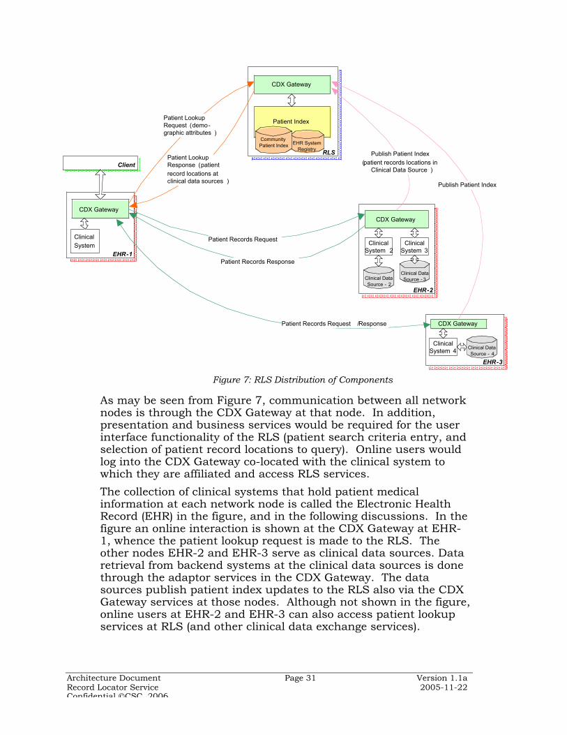
As may be seen from Figure 7, communication between all networknodes is through the CDX Gateway at that node. In addition,presentation and business services would be required for the userinterface functionality of the RLS (patient search criteria entry, andselection of patient record locations to query). Online users wouldlog into the CDX Gateway co-located with the clinical system towhich they are affiliated and access RLS services.
The collection of clinical systems that hold patient medicalinformation at each network node is called the Electronic HealthRecord (EHR) in the figure, and in the following discussions. In thefigure an online interaction is shown at the CDX Gateway at EHR-1, whence the patient lookup request is made to the RLS. Theother nodes EHR-2 and EHR-3 serve as clinical data sources. Dataretrieval from backend systems at the clinical data sources is donethrough the adaptor services in the CDX Gateway. The datasources publish patient index updates to the RLS also via the CDXGateway services at those nodes. Although not shown in the figure,online users at EHR-2 and EHR-3 can also access patient lookupservices at RLS (and other clinical data exchange services).
EHR-3
EHR-2
EHR-1
RLS
Patient Index
CDX Gateway
CDX Gateway
CDX Gateway
CDX Gateway
Clinical System
Client
Patient LookupRequest (demo-graphic attributes )
Patient LookupResponse (patientrecord locations atclinical data sources )
Patient Records Request
Patient Records Response
Publish Patient Index (patient records locations in
Clinical Data Source )
Patient Records Request /Response
Clinical System 3
Publish Patient Index
EHR System Registry
Community Patient Index
Clinical Data Source - 2
Clinical Data Source - 3
Clinical Data Source - 4
Clinical System 2
Clinical System 4
Figure 7: RLS Distribution of Components
Architecture Document Page 32 Version 1.1aRecord Locator Service 2005-11-22Confidential CSC, 2006
RLS receives service requests through a CDX Gateway at itslocation. RLS needs an administrative user interface to manage theapplication, which would be the responsibility of the presentationand business services in the gateway at the RLS.
The gateway based architecture provides significant flexibility andscalability. More clinical data sources could be added by deployinga CDX Gateway at that location and customizing adaptors toconnect with the clinical system there. The Gateway transformslocal message formats into standard ones and manages theirsecure, reliable communication to other Gateways.
In general, the expectation is that CDX Gateways that areapproximate clones of each other would simplify deployment,configuration and administration of this distributed service. TheCDX Gateway, thus, serves as a general utility service that may beplugged in at different EHR locations. In addition the CDX Gatewayserves as an infrastructure component which realizes the commonframework standards in a packaged form.
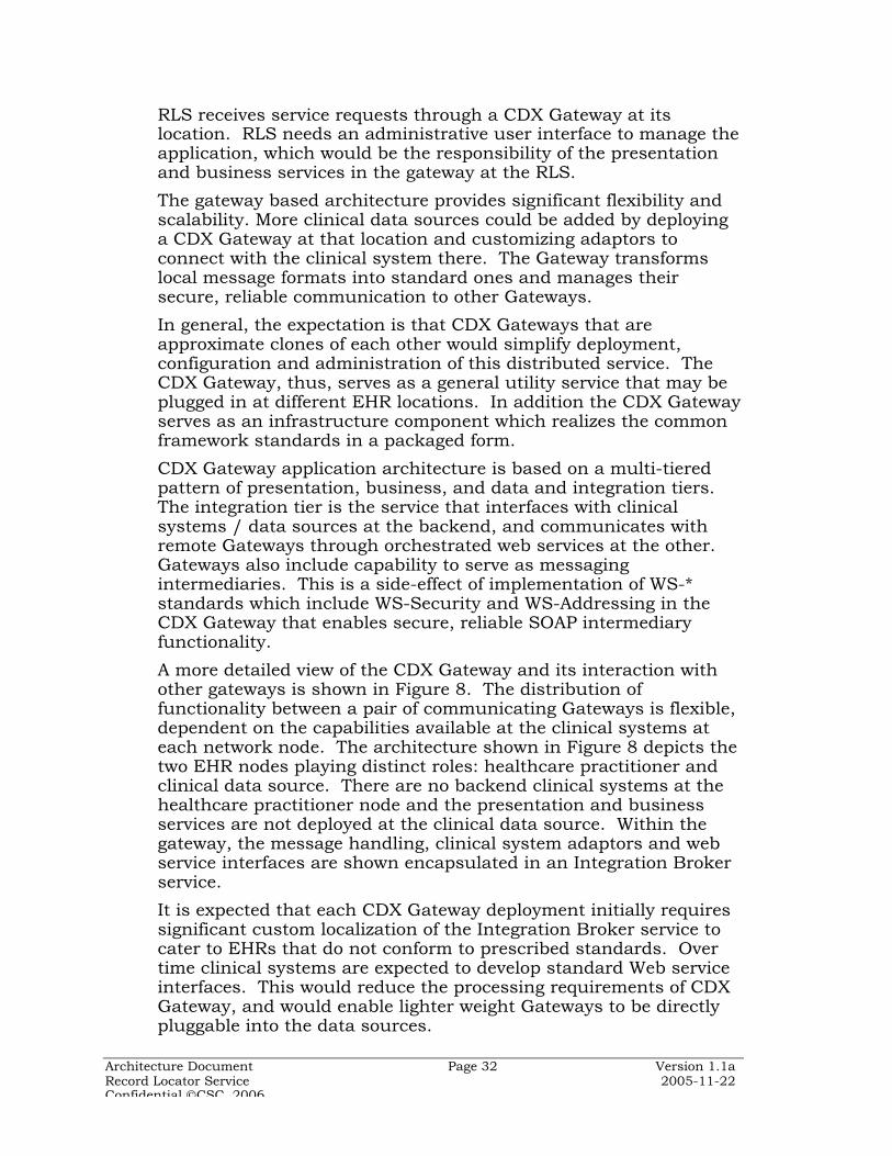
CDX Gateway application architecture is based on a multi-tieredpattern of presentation, business, and data and integration tiers.The integration tier is the service that interfaces with clinicalsystems / data sources at the backend, and communicates withremote Gateways through orchestrated web services at the other.Gateways also include capability to serve as messagingintermediaries. This is a side-effect of implementation of WS-*standards which include WS-Security and WS-Addressing in theCDX Gateway that enables secure, reliable SOAP intermediaryfunctionality.
A more detailed view of the CDX Gateway and its interaction withother gateways is shown in Figure 8. The distribution offunctionality between a pair of communicating Gateways is flexible,dependent on the capabilities available at the clinical systems ateach network node. The architecture shown in Figure 8 depicts thetwo EHR nodes playing distinct roles: healthcare practitioner andclinical data source. There are no backend clinical systems at thehealthcare practitioner node and the presentation and businessservices are not deployed at the clinical data source. Within thegateway, the message handling, clinical system adaptors and webservice interfaces are shown encapsulated in an Integration Brokerservice.
It is expected that each CDX Gateway deployment initially requiressignificant custom localization of the Integration Broker service tocater to EHRs that do not conform to prescribed standards. Overtime clinical systems are expected to develop standard Web serviceinterfaces. This would reduce the processing requirements of CDXGateway, and would enable lighter weight Gateways to be directlypluggable into the data sources.
Architecture Document Page 33 Version 1.1aRecord Locator Service 2005-11-22Confidential CSC, 2006
CDX Gateways communicate with each other using Web servicesprotocol (WSDL and SOAP) over the standard HTTP/SSL transportprotocol. Gateways could extend in future to adopt alternatetransport protocol such as Secure FTP for batch file transfer, andSMTP using industry standard S/MIME encryption for email.
Figure 8: Gateway based interaction in a health information network
4.4 RLS-Based Networks
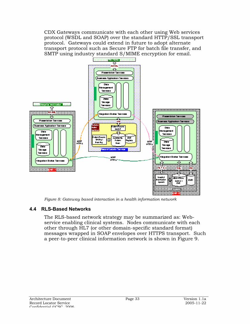
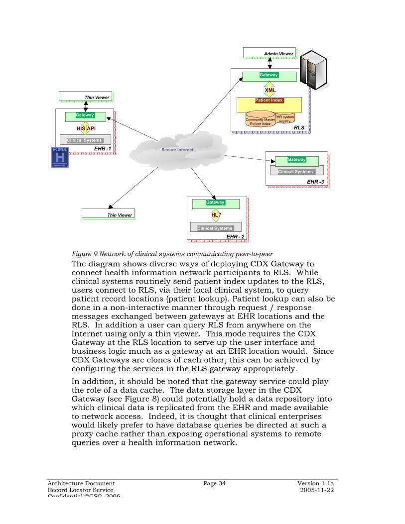
The RLS-based network strategy may be summarized as: Web-service enabling clinical systems. Nodes communicate with eachother through HL7 (or other domain-specific standard format)messages wrapped in SOAP envelopes over HTTPS transport. Sucha peer-to-peer clinical information network is shown in Figure 9.
Architecture Document Page 34 Version 1.1aRecord Locator Service 2005-11-22Confidential CSC, 2006
EHR - 2
Gateway
Clinical Systems
HL7
EHR -1
Gateway
Clinical Systems
HIS API
Thin Viewer
RLS
Gateway
XML
EHR system registry
Patient Index
Community Master Patient Index
EHR -3
Clinical Systems
Thin Viewer
Secure Internet
Gateway
Admin Viewer
Figure 9 Network of clinical systems communicating peer-to-peer
The diagram shows diverse ways of deploying CDX Gateway toconnect health information network participants to RLS. Whileclinical systems routinely send patient index updates to the RLS,users connect to RLS, via their local clinical system, to querypatient record locations (patient lookup). Patient lookup can also bedone in a non-interactive manner through request / responsemessages exchanged between gateways at EHR locations and theRLS. In addition a user can query RLS from anywhere on theInternet using only a thin viewer. This mode requires the CDXGateway at the RLS location to serve up the user interface andbusiness logic much as a gateway at an EHR location would. SinceCDX Gateways are clones of each other, this can be achieved byconfiguring the services in the RLS gateway appropriately.
In addition, it should be noted that the gateway service could playthe role of a data cache. The data storage layer in the CDXGateway (see Figure 8) could potentially hold a data repository intowhich clinical data is replicated from the EHR and made availableto network access. Indeed, it is thought that clinical enterpriseswould likely prefer to have database queries be directed at such aproxy cache rather than exposing operational systems to remotequeries over a health information network.

Architecture Document Page 35 Version 1.1aRecord Locator Service 2005-11-22Confidential CSC, 2006
4.5 Regional and National Network Support
Current thinking on national health information network envisagesinterconnected exchanges hosted by Regional Health InformationOrganizations (RHIOs). Such a network of networks is shown inFigure 10.
Figure 10 Network of RLS-based networks (potentially used by RHIO)
The RLS architecture itself presumes no regional dimension; thescoping function of the RLS is the community master patient indexthat maintains pointers to patient records in distributed EHRs inthe community. However, RLS clearly is a candidate for the centralcoordinating service of a RHIO network. In regards to inter-RHIOcommunication, it is easy to see that the RLS could also play a keyrole in routing and coordination of services across RHIOs.
Some RHIOs may be based upon a centralized data repository asdetermined by regional policy considerations (as well as legacyarchitectural considerations); others are decentralized. Bothmodels, as well as intermediate ones, are supported by theproposed NHIN architecture. Using a common framework based onopen standards and common policies allows a RHIO to be agnosticabout the architecture of another RHIO. The service oriented CDXGateway architecture also enables a degree of flexibility inimplementation styles and operational configuration as discussedfurther in the following section.
National Health Information Network
RLS C
C EHR 1
C EHR 2
RLS A
A EHR 1A EHR 2
RLS B
B EHR 1
B EHR 2
A EHR ...B EHR ...
C EHR ...
RHIO ARHIO B
RHIO C

Architecture Document Page 36 Version 1.1aRecord Locator Service 2005-11-22Confidential CSC, 2006
5 Process View
The RLS application is a collection of loosely-coupled interoperableservices, and is itself a service that can be invoked by externalconsumers. Components that are distributed across network nodescommunicate via XML messages using Web service standards,primarily SOAP and WSDL. Additional Web service standards maybe used to support reliable messaging, error handling, and security.
The essential RLS functions to fulfill the patient lookup and publishpatient index use cases are realized through distributed processingof the RLS services as described below.
5.1 Patient Lookup and Peer to Peer Medical Records Retrieval
The patient lookup process may be visualized as shown in thesimplified communication diagram in Figure 11, where the flow ofinformation and messages between the distributed processingcomponents may be tracked through the sequence numbersprovided.
EHR
EHR
RLS
EHR
Healthcare Practitioner
17
8
9 10
111213
14
CDX Gateway
Clinical System
CDX Gateway
Patient IndexCDX
Gateway2
3
CMPI
4
56
1. Patient demographics query parameters2. Patient lookup query request in SOAP envelope3. Matching engine search parameters4. Matching records from MPI query / response5. Patient record locations6. Patient record locations in SOAP envelope7. Patient record locations for selection
8. Patient medical records request9. Request message in SOAP envelope10. Medical records request in EHR format11. Database /application request / response12. Medical records13. Medical records in SOAP envelope14. Aggregated medical records
Clinical System
EHR
Figure 11: Patient Lookup with RLS and Medical Records Retrieval through CDXGateways
The interaction diagram illustrates the use of gateways to manageall communications between network nodes. Gateways alsoencapsulate presentation, business, and data access servicesthereby providing a full application stack for flexibleimplementation of RLS services. For example, while the patientlookup is shown as an interactive process it could as well betransacted offline, in batch mode.
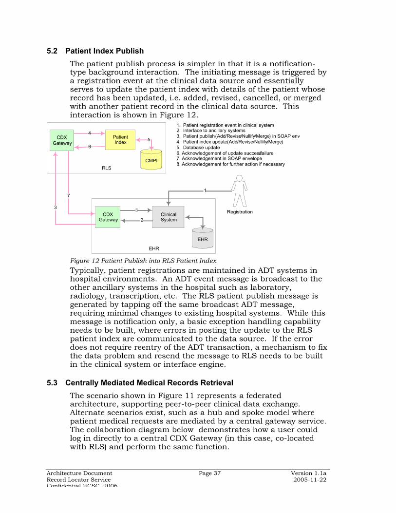
Architecture Document Page 37 Version 1.1aRecord Locator Service 2005-11-22Confidential CSC, 2006
5.2 Patient Index Publish
The patient publish process is simpler in that it is a notification-type background interaction. The initiating message is triggered bya registration event at the clinical data source and essentiallyserves to update the patient index with details of the patient whoserecord has been updated, i.e. added, revised, cancelled, or mergedwith another patient record in the clinical data source. Thisinteraction is shown in Figure 12.
EHR
RLS
EHR
Patient Index
CMPI
Registration
5
6
4
7
8
2
3
CDX Gateway
CDX Gateway
Clinical System
1. Patient registration event in clinical system2. Interface to ancillary systems 3. Patient publish (Add/Revise/Nullify/Merge) in SOAP env4. Patient index update (Add/Revise/Nullify/Merge)5. Database update6. Acknowledgement of update success/failure7. Acknowledgement in SOAP envelope8. Acknowledgement for further action if necessary
1
Figure 12 Patient Publish into RLS Patient Index
Typically, patient registrations are maintained in ADT systems inhospital environments. An ADT event message is broadcast to theother ancillary systems in the hospital such as laboratory,radiology, transcription, etc. The RLS patient publish message isgenerated by tapping off the same broadcast ADT message,requiring minimal changes to existing hospital systems. While thismessage is notification only, a basic exception handling capabilityneeds to be built, where errors in posting the update to the RLSpatient index are communicated to the data source. If the errordoes not require reentry of the ADT transaction, a mechanism to fixthe data problem and resend the message to RLS needs to be builtin the clinical system or interface engine.
5.3 Centrally Mediated Medical Records Retrieval
The scenario shown in Figure 11 represents a federatedarchitecture, supporting peer-to-peer clinical data exchange.Alternate scenarios exist, such as a hub and spoke model wherepatient medical requests are mediated by a central gateway service.The collaboration diagram below demonstrates how a user couldlog in directly to a central CDX Gateway (in this case, co-locatedwith RLS) and perform the same function.

Architecture Document Page 38 Version 1.1aRecord Locator Service 2005-11-22Confidential CSC, 2006
EHR
RLS
EHR
Patient Index
CMPI
Healthcare Practitioner
15
36
4
2
7
8
9
10
11
12
CDX Gateway
CDX Gateway
Clinical System
1. Patient demographics query parameters2. Search engine query parameters 3. Probabilistically matched records query /response4. Patient records locations5. Patient record locations for selection
6. Patient medical records request7. Request in SOAP envelope8. Medical records request in EHR format9. Database /application request / response10. Medical records11. Medical records in SOAP envelope12. Aggregated medical records
Figure 13 Centrally Mediated Patient Lookup and Record Retrieval (hostedgateway)
Note that the healthcare practitioner is shown as logging directlyinto the gateway at the RLS location and executing the patientlookup query directly on RLS. This is another variation of the useof the CDX Gateway, and demonstrates the implementationflexibility a standard gateway utility based network architectureallows.
5.4 Central Medical Records Aggregation
Yet another processing model would remove the need for a two stepprocess altogether and have the patient lookup request becombined with a medical records request which the CDX Gatewayat the RLS would orchestrate. Such a scenario is shown in Figure14.
EHR
RLS
EHR
Patient Index
CMPI
Healthcare Practitioner
1
3
4
2
5
6
7
8
9
10
CDX Gateway
CDX Gateway
Clinical System
1. Patient demographics query parameters2. Search engine query parameters 3. Probabilistically matched records query / response4. Patient records locations
5. Request in SOAP envelope6. Medical records request in EHR format7. Database /application request / response8. Medical records9. Medical records in SOAP envelope10. Aggregated medical records
Figure 14 Patient Lookup and Records Retrieval -- In One Step

Architecture Document Page 39 Version 1.1aRecord Locator Service 2005-11-22Confidential CSC, 2006
This interaction pattern is more appropriate for unattended RLSusage where a clinical system collects remote patient records andhas them ready for review by a healthcare practitioner at later time.The orchestration process in the CDX Gateway is now morecomplex and should implement workflow processes of thehealthcare practitioner, including selection of appropriate medicalrecords to retrieve from various sources.
Other supplementary processes include the need for secureinformation sharing, and the establishment of contracts betweenthe RLS and the various clinical data sources that would sharepatient medical records with each other. In both of these situationsRLS, serves as a trusted intermediary, and reduces the need for themany-to-many relationships between the various clinical datasources. The secure messaging process is described below.
5.5 Security Processes
RLS needs a security framework to authenticate users, authorizeaccess to specific services, and ensure confidentiality and integrityof messages. The implementation of security across a disparate,distributed computing network is optimally effected through afederated identity management architecture, where each user isauthenticated by an assigned node that vouches for the user toother nodes. Federated security architecture is complex andconsidered beyond the scope of the current release of RLS. RLSuses a simpler model that can be extended to a federatedarchitecture in later releases.
A distributed authentication/authorization architecture that isbased on overlapping trust relationships is shown in Figure 15.Users’ identity and credentials are maintained at the gateway thatthey log in to. Gateways are within the clinical enterprise domain,and may be integrated with the enterprise security infrastructure tosupport single sign-on for users. Gateways are in a trustrelationship with other gateways and authenticate each otherthrough server-side certificates. An authentication / authorizationassertion is communicated in the SOAP message along with theuser identifier string for audit purposes.
Secure Socket Layer (SSL) is a session layer protocol for sendingencrypted information over HTTP. SSL provides an encryptedchannel with confidentiality, integrity and one-way or two-wayauthentication. SSL is used to secure messages between gatewaysin the RLS-based network. Gateway authentication may be providedby server-side digital certificates.
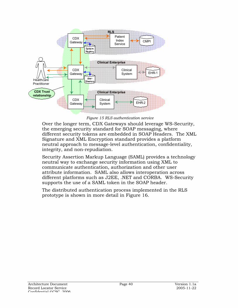
Architecture Document Page 40 Version 1.1aRecord Locator Service 2005-11-22Confidential CSC, 2006
Figure 15 RLS authentication service
Over the longer term, CDX Gateways should leverage WS-Security,the emerging security standard for SOAP messaging, wheredifferent security tokens are embedded in SOAP Headers. The XMLSignature and XML Encryption standard provides a platformneutral approach to message-level authentication, confidentiality,integrity, and non-repudiation.
Security Assertion Markup Language (SAML) provides a technologyneutral way to exchange security information using XML tocommunicate authentication, authorization and other userattribute information. SAML also allows interoperation acrossdifferent platforms such as J2EE, .NET and CORBA. WS-Securitysupports the use of a SAML token in the SOAP header.
The distributed authentication process implemented in the RLSprototype is shown in more detail in Figure 16.
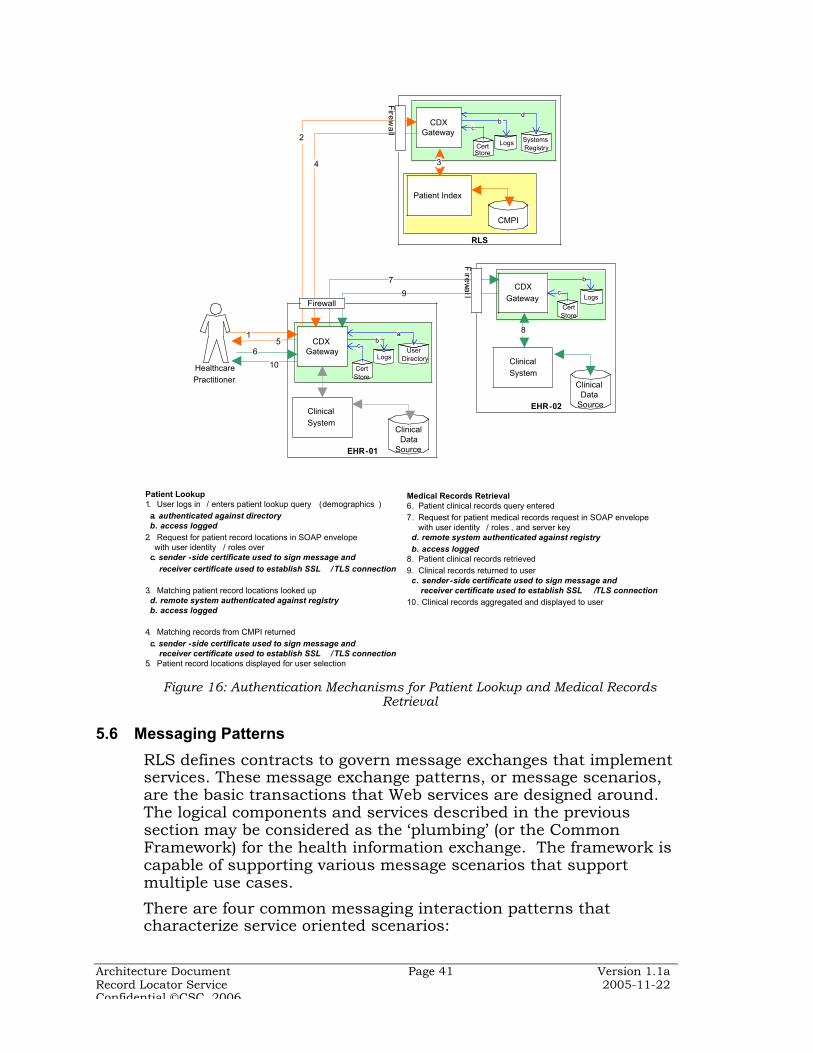
Architecture Document Page 41 Version 1.1aRecord Locator Service 2005-11-22Confidential CSC, 2006
RLS
EHR-02
EHR-01
Healthcare Practitioner
15
6
7
8
9
10
CDX Gateway
Clinical System
CDX Gateway
Patient Index
CDX Gateway
2
CMPI
4
Clinical System
ClinicalData
Source
Firewall
Fire
wa
ll
Fire
wa
ll
3
Medical Records Retrieval6. Patient clinical records query entered 7. Request for patient medical records request in SOAP envelope with user identity / roles , and server key d. remote system authenticated against registry b. access logged8. Patient clinical records retrieved 9. Clinical records returned to user c. sender-side certificate used to sign message and receiver certificate used to establish SSL /TLS connection10. Clinical records aggregated and displayed to user
User Directory
a
SystemsRegistry
Logs
db
Logs
Logs
b
b
CertStore
c
CertStore
c
CertStore
c
ClinicalData
Source
Patient Lookup1. User logs in / enters patient lookup query (demographics ) a. authenticated against directory b. access logged2. Request for patient record locations in SOAP envelope with user identity / roles over c. sender -side certificate used to sign message and receiver certificate used to establish SSL /TLS connection
3. Matching patient record locations looked up d. remote system authenticated against registry b. access logged
4. Matching records from CMPI returned c. sender -side certificate used to sign message and receiver certificate used to establish SSL /TLS connection5. Patient record locations displayed for user selection
Figure 16: Authentication Mechanisms for Patient Lookup and Medical RecordsRetrieval
5.6 Messaging Patterns
RLS defines contracts to govern message exchanges that implementservices. These message exchange patterns, or message scenarios,are the basic transactions that Web services are designed around.The logical components and services described in the previoussection may be considered as the ‘plumbing’ (or the CommonFramework) for the health information exchange. The framework iscapable of supporting various message scenarios that supportmultiple use cases.
There are four common messaging interaction patterns thatcharacterize service oriented scenarios:
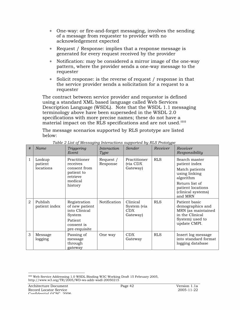
Architecture Document Page 42 Version 1.1aRecord Locator Service 2005-11-22Confidential CSC, 2006
∗ One-way: or fire-and-forget messaging, involves the sendingof a message from requester to provider with noacknowledgement expected
∗ Request / Response: implies that a response message isgenerated for every request received by the provider
∗ Notification: may be considered a mirror image of the one-waypattern, where the provider sends a one-way message to therequester
∗ Solicit response: is the reverse of request / response in thatthe service provider sends a solicitation for a request to arequester
The contract between service provider and requestor is definedusing a standard XML based language called Web ServicesDescription Language (WSDL). Note that the WSDL 1.1 messagingterminology above have been superseded in the WSDL 2.0specifications with more precise names; these do not have amaterial impact on the RLS specifications and are not used.‡‡‡‡
The message scenarios supported by RLS prototype are listedbelow:
Table 2 List of Messaging Interactions supported by RLS Prototype
# Name TriggeringEvent
InteractionType
Sender Receiver ReceiverResponsibility
1 Lookuppatientlocations
Practitionerreceivesconsent frompatient toretrievemedicalhistory
Request /Response
Practitioner(via CDXGateway)
RLS Search masterpatient indexMatch patientsusing linkingalgorithmReturn list ofpatient locations(clinical systems)and MRN
2 Publishpatient index
Registrationof new patientinto ClinicalSystemPatientconsent ispre-requisite
Notification ClinicalSystem (viaCDXGateway)
RLS Patient basicdemographics andMRN (as maintainedin the ClinicalSystem) used toupdate CMPI.
3 Messagelogging
Passing ofmessagethroughgateway
One way CDXGateway
RLS Insert log messageinto standard formatlogging database
‡‡‡‡ Web Service Addressing 1.0 WSDL Binding W3C Working Draft 15 February 2005,http://www.w3.org/TR/2005/WD-ws-addr-wsdl-20050215

Architecture Document Page 43 Version 1.1aRecord Locator Service 2005-11-22Confidential CSC, 2006
# Name TriggeringEvent
InteractionType
Sender Receiver ReceiverResponsibility
4 Exceptionlogging
Errorcondition inmessageprocessing
One way CDXGateway
RLS Insert error messageinto standard formatlogging databaseand notifyAdministrator
5 Retrievemedicationhistoryrecords:
Authorizedpractitionersubmitsrequest.Patientconsent ispre-requisite
Request /Response
Practitioner(via CDXGateway)
ClinicalSystemvia CDXGateway
Return requestedmedication historylist in a standardmessage format
Each message scenario assumes that an error message (SOAPFault) is returned by the receiver to the sender if the messageresults cannot be parsed or results in any application error.
The flow of logic across the different service layers in the RLS /CDX Gateway solution architectures is shown as sequencediagrams in Figure 17 and Figure 18 where the application processlogic may be visualized as a series of messages exchanged betweenapplication services. The services oriented architecture is realizedthrough implementation of messaging between applicationcomponents, as shown here. Figure 17 depicts the interactionsbetween RLS application components to provide the patient lookupservice to users logging in to remote gateways.

Architecture Document Page 44 Version 1.1aRecord Locator Service 2005-11-22Confidential CSC, 2006
Figure 17 Patient lookup sequence diagram
As can be see in the figure, the Gateway services communicate witheach other through the integration broker services.
The other core RLS service is that of accepting updates to patientindices from clinical data sources and applying them to the RLSCMPI. This may be visualized in the sequence diagram in Figure18.
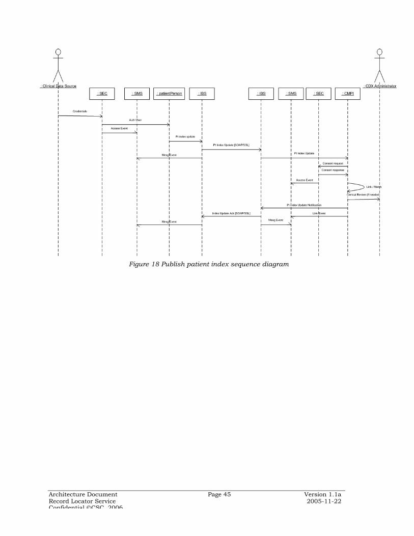
Architecture Document Page 45 Version 1.1aRecord Locator Service 2005-11-22Confidential CSC, 2006
Figure 18 Publish patient index sequence diagram

Architecture Document Page 46 Version 1.1aRecord Locator Service 2005-11-22Confidential CSC, 2006
6 Implementation View
This section describes how the relevant components of the RLSlogical architecture are implemented. While the logical and processviews provide more conceptual models of RLS, the implementationand deployment views relate more to the physical artifacts thatmake up the RLS-based interoperability framework. Theimplementation view presents a more detailed view of theorganization of the static software elements of the RLS prototypethan was presented in the logical view.
Note that implementation of systems based on the RLS architectureis to be undertaken by individual RHIOs, which have significantlatitude of action. Each RHIO may choose implementationstrategies based on their internal development methods andplatform preferences. This section provides only genericimplementation related information, and refers to the RLS prototypeimplementation architecture and platform for purely illustrativepurposes.
RLS architecture is generic and platform agnostic, withinteroperability based on open connectivity standards such as Webservices, and semantic data standards such as the HL7 ReferenceInformation Model. This section also outlines the relevantstandards prescribed for an RLS implementation. Given thatinteroperability is critically dependent on the communication anddata standards adopted, the expectation is that eachimplementation adheres closely to the recommended standards andspecifications. More detailed guidance on implementing messageformat standards and specifications is provided in a separatedocument: RLS Messaging Communication Implementation Guide.
6.1 Overview
RLS is a classic n-tiered database application with a web-browserbased user interface, and capability to interoperate with remotesystems using open standard messaging over the Internet. The keyinteroperability function is realized through implementing agateway service at each node in the network that provides essentialpresentation, business and data services and the ability tocommunicate with other gateways using web services and domainspecific data standards. The RLS application may be viewed ascomprising two large grained components (or service compositions).
¶ Patient Index service maintains and enables access to the communityMaster Patient Index (CMPI) and maintains a community directory /registry for the various clinical data sources, data and messagestandards, etc.
Architecture Document Page 47 Version 1.1aRecord Locator Service 2005-11-22Confidential CSC, 2006
¶ CDX Gateways provides a ‘web-service’ wrapper and other utilityservices to support message based interoperation for the RLS as wellas for each clinical data source in the network.
The patient index service architecture essentially comprisescomponents that provide Patient Record Linking / Matching andPatient Record Search services. The CMPI database contains basicpatient demographic information and patient identifiers asmaintained in the various clinical data sources that publish intothe CMPI. Each patient record is tagged with the networkresolvable address of its source.
The unified patient view is achieved through linking / matching ofpatient records based on demographic attributes. Record matchingmay use deterministic (exact) matching of patient demographicattributes or a probabilistic algorithm which takes into account thevariations in source data due to data entry anomalies. Thearchitecture implementation supports the swapping of matchingalgorithms by change of run-time parameters.
CDX Gateways enable the interoperation of backend legacy clinicalsystems with each other and with the RLS through exchange ofmessages (of various formats) with other gateways using Webservices protocols over HTTP transport secured with SSL/TLS (orHTTPS).
6.2 Components and Layers
A logical view of the RLS application architecture was presented inSection 4.

Architecture Document Page 48 Version 1.1aRecord Locator Service 2005-11-22Confidential CSC, 2006
A more detailed breakdown of the components of the RLS, theirlogical groupings (layers), and implementation platforms used inthe prototype project is shown in Figure 19
Figure 19 RLS and CDX Gateway components and sample (prototype)implementation platforms
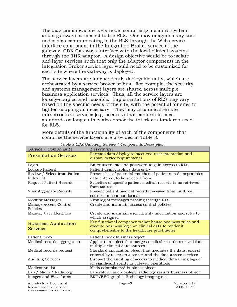
Architecture Document Page 49 Version 1.1aRecord Locator Service 2005-11-22Confidential CSC, 2006
The diagram shows one EHR node (comprising a clinical systemand a gateway) connected to the RLS. One may imagine many suchnodes also communicating to the RLS through the Web serviceinterface component in the Integration Broker service of thegateway. CDX Gateways interface with the local clinical systemsthrough the EHR adaptor. A design objective would be to isolateand layer services such that only the adaptor components in theIntegration Broker service layer would need to be customized foreach site where the Gateway is deployed.
The service layers are independently deployable units, which areorchestrated by a service broker or bus. For example, the securityand systems management layers are shared across multiplebusiness application services. Thus, all the service layers areloosely-coupled and reusable. Implementations of RLS may varybased on the specific needs of the site, with the potential for sites totighten coupling as necessary. They may also use alternateinfrastructure services (e.g. security) that conform to localstandards as long as they also honor the interface standards usedfor RLS.
More details of the functionality of each of the components thatcomprise the service layers are provided in Table 3.
Table 3 CDX Gateway Service / Components DescriptionService / Components Description
Presentation Services Formats data display to meet end user interaction anddisplay device requirements
Login Enter username and password to gain access to RLSLookup Patient Patient demographics data entryReview / Select from PatientIndex list
Present list of potential matches of patients to demographicsdata entered, to be selected from
Request Patient Records Selection of specific patient medical records to be retrievedfrom source
View Aggregate Records Present patient medical records received from multiplesources in common format
Monitor Messages View log of messages passing through RLSManage Access ControlPolicies
Create and maintain access control policies
Manage User Identities Create and maintain user identity information and roles towhich assigned
Business ApplicationServices
Key functional components that house business rules andexecute business logic on clinical data to render itcomprehensible to the healthcare practitioner
Patient index Patient index business objectMedical records aggregation Application object that merges medical records received from
multiple clinical data sourcesMedical records request Standard application object that mediates the data request
entered by users on a screen and the data access servicesAuditing Services Support the auditing of access to medical data using logs of
all significant events in gateway operationsMedication list Meds administered business objectLab / Micro / Radiology Laboratory, microbiology, radiology results business objectImages and Waveforms EKG/EEG graphs, Radiology imaging etc.

Architecture Document Page 50 Version 1.1aRecord Locator Service 2005-11-22Confidential CSC, 2006
Service / Components DescriptionNotes / Reports Clinical documentation business objectVisit History Patient encounters business objectProblem list List of current diagnoses business object
Data ManagementServices
Manage application access to data storage and processing ofdata in data storage layer. Isolates the business layer fromthe details of the data storage service. Supportsmanagement of metadata about data stores and repositoriesin system
Persistence / Data Access Provide standard data access to business application servicesthat is independent of the underlying data storage technologyor database management systems
Code sets and Keymanagement
Manage disparate code sets and generated keys for dataimported from multiple systems
Replication, backup, datacache management
Technical data management services. Support dataaggregation and asynchronous data streams managementData cache for clinical data (where required).
Data Storage Services Provide reliable, secure data storage for efficient access bydata management services
Data Cache For storing temporary copies of data retrieved from clinicaldata sources for faster response to user queries. This couldbe a significant component for pilot / productionimplementation since it buffers the clinical data sources fromexternal queries. However, there are significant business andtechnical issues to be resolved for clinical data caching.
Message store, Logs and Audit Persistence mechanism for reliable messaging and formonitoring of message flow (may be part of SystemManagement Services)
User directory, Certificatesstore
Data store for security services layer (may be part of SecurityServices)
XML Schema and metadataservices
Repository of message and data standards for reference –both run time and design time
Integration BrokerServices
Manages flow of messages through the Gateway that servesRLS and the clinical systems that communicate with RLS
Message Queuing andTransport
Provides store-and-forward capability and managesconnection to messaging infrastructure. Supportsasynchronous messaging between loosely coupled services
Message translation Transform message formats based on mappingsRouting / Orchestration Routes messages to the appropriate destination channelsWeb Services Interface SOAP and WSDL processing along with other WS-* service
implementations, e.g. reliable messaging, error handling,security
XML Processing Serialization/deserialization of messages, validation ofmessages against XML schema, and translation from oneschema to another using XSLT
HL7 Mapping Conversion from HL 2.x messages to RLS standard formats(HL7 v3)
EHR Adaptor EHR system specific component with ability to extractrequired medical records from EHR system
MPI Adaptor Component to interface with Master Patient Indexes(including CMPI)
SQL / Replication / ETLAdaptor
Data movement from one data store to another, includestransformation as needed and typically executed in batch(bulk) mode
Systems ManagementServices
Besides application management functions shown below,extends over the long term to cover remote deployment,configuration, administration and patch application ofdistributed Gateway from central location

Architecture Document Page 51 Version 1.1aRecord Locator Service 2005-11-22Confidential CSC, 2006
Service / Components DescriptionServices extends over the long term to cover remote deployment,
configuration, administration and patch application ofdistributed Gateway from central location
Logging services Interface for application to log processing eventsException Handling Services Interface to raise and manage errors in application
processingConfiguration Interface to manage the configuration of the RLS application.
E.g. setting record linking /matching algorithm, logginglevels etc.
Security Services Manage the implementation of security to control access tothe system and protect confidentiality and integrity of data inthe system
User / Roles Management Manage the creation, updates, and deletion of actorsauthorized to use RLS
Authentication /Authorization /Personalization
Validate that actors (user or system) is who/what they claimto be
Consent Management Manage individual patients consent to let healthcarepractitioners view their medical records
Policy Management Provide interface to configure and manage rules for access tohealthcare data, auditing, and secure operation of RLS
The services that make up the Patient Index Service of RLS aredescribed in Table 4.
Table 4 RLS Components DescriptionService / Component Description
Patient Index Services Maintain patient records sourced from multiple clinicalsystems and provide access to data
Community Master PatientIndex
Multi-enterprise Patient Index data store maintained in theRLS
Patient Records Linking /Indexing
Identify multiple patient records pertaining to the sameindividual, but created with potentially different attributes
Patient Record Search Search for index for patients matching the demographicattributes entered by healthcare practitioner
The interfaces between the application components shown are thesubject of local implementation decisions. The general bias of SOA-based applications is to use XML messaging interfaces betweencomponents. The CDX Gateway integration broker service may beused as a ‘service bus’ that mediates connections between thecoarse grained services that make up the SOA-based application. Itshould be recognized that a messaging interface often has a systemperformance overhead and that this penalty may not, in someimplementations, be fully offset by the benefits of true loosecoupling of application components. In such cases,implementations may choose to start with tighter RPC-styleinterfaces between application components, and migrate to SOA asperformance management allows.

Architecture Document Page 52 Version 1.1aRecord Locator Service 2005-11-22Confidential CSC, 2006
6.3 Implementation Topology Options
As shown in Section 5 there are several processing models that canbe implemented with the gateway based network architecture.Each gateway is an n-tier application with distinct presentation,application, data storage and integration services. This allows thefunctionality and data storage at each gateway service to be variedbased on the degree of centralization or decentralization desired.
Being based on the Internet, the health information network has afully connected mesh topology at the transport (and connectivity)level. The application and data distribution across the networknodes determine whether an interaction between nodes is server-based or peer-to-peer. In server-based networks some computers(clients) consume services provided by others (servers). In a peer-to-peer network, the computers on the network can act both asclients and servers, and are referred to as peers. The RLS-basedhealth information network is a hybrid, with some key services(record location) being provided centrally, while others (clinical dataexchange) are consumed on a peer-to-peer basis.
RLS’ service oriented application architecture (SOA) and the Webservice based network supports multiple application and networkconfigurations with varying degrees of data and applicationdistribution. This derives from the fact that a loosely coupled, peer-to-peer model offers the ability to ‘tighten’ the coupling or centralizethe architecture as needed by local implementations, whereas apriori centralization does not offer such flexibility. In effect the RLS-based network leverages the strengths of the Internet where a fullyconnected network allows varying service topologies to be usedbased on requirements.
The RLS-based network architecture seeks to find the right balancebetween being a potential single point of failure in the middle andreducing the processing footprint at the nodes. The proposed SOAmodel enables the intra-RLS service distribution to be adjusted andtuned for optimal performance at local, regional and national scale.
A case for data decentralization can also be built on patient privacyprotection grounds. Recent security episodes and public perceptionsuggest that the likelihood of data spills is reduced by not creatinga large centralized repository of patient health information. Leavingprotected health information in local clinical systems, and using afederated peer-to-peer clinical data exchange model reduces thelikelihood of catastrophic data spills. Where local clinical systemsare accessible from the network, the architecture anticipates databeing cached by a hosted gateway service, which would serve as aproxy for the legacy clinical system (similar to an application serviceprovider (ASP) model – a hybrid variation on centralized services).

Architecture Document Page 53 Version 1.1aRecord Locator Service 2005-11-22Confidential CSC, 2006
An additional consideration is the messaging architecture for inter-RLS communication. Given that the health information networknodes are all Web-addressable each RLS sub-network node couldconnect to a remote RLS sub-network node on a peer-to-peer basis.However, as the security discussion indicates the need for eachnode to authenticate to each other impacts the scalability of suchconnectivity. An intermediary bridging service is required that canalso be provided by the CDX Gateway at the RLS.
The different implementation options are listed in Table 5 below.Table 5 Implementation Topology Options
ImplementationTopology
Description Decision Criteria
Peer-to-peer usinggateways fortransport mediationand aggregation
Clinical data are distributed andmanaged within their clinicalsystems
Central patient registry for recordlocation
Gateways translate messages fromlocal to network standard format
Message and data aggregation ateach gateway node
Service oriented architecture providesmaximum flexibility in linkingdisparate systems
No single point of failure (SPOF)
No centralized command and control
Increased mediation/ aggregationfunctionality at Gateway … complexdistributed administration
Peer-to-peer withgatewaysmaintaining clinicaldata caches
Gateways in addition to facilitatinginterconnectivity also serve asproxies for clinical data stores
Clinical data sources maintainautonomy
Operational clinical systems are notsubject to unpredictable query loadsfrom network users
Data replication needs to be set upand maintained between clinicaldatabase and proxy cache
Hub and spoke withdistributed datasources usingcentral mediationservice for messagerouting
While clinical data remains atnetwork nodes, messages are allrouted through a central service
Central service handles messageand data aggregation
The gateway at the RLS could serve asthe central routing and mediationservice
Lighter weight gateways at the edgesminimize network joining overhead
Hub and spoke withcentral datarepository
Variation of the distributed proxydata cache wherein data fromclinical data sources are moved tocentral data repository
Gateway function is purelytransport mediation
Increased central data managementand security overhead
Reduced participation rates fromclinical enterprises
Very light-weight distributed gateway
High degree of data conformityrequired

Architecture Document Page 54 Version 1.1aRecord Locator Service 2005-11-22Confidential CSC, 2006
ImplementationTopology
Description Decision Criteria
Inter-RLS datasharing on a peer-to-peer basis
Use Gateway service at eachclinical system to communicateacross RLS sub-networks
Sharing of information acrosscommunities needs to be independentof data distribution with the RLS sub-network
Trust relationships need to be built onvery large scale across all nodes in allsub-networks
Inter-RLS datasharing using a‘central’intermediary service
Use the RLS Gateway to provideintermediary services to mediatepatient lookup and clinical dataexchange between different sub-networks
Trust relationships need exist onlywithin an RLS sub-network andbetween RLSs
Centralization and distribution are relative concepts and networktopologies typically exist somewhere on a continuum between thetwo. The RLS architecture principle of federated data andcentralized directories is currently considered best practice, butmay well need to adapt to different models as technologies evolve.The above list of possible implementation options shows that theproposed architecture is flexible and adaptive.
6.4 Security Model
The RLS architecture principles recommend a delegatedauthentication model as the most practical approach to achievingthe rigorous security and privacy demands on a health informationnetwork. Users are authenticated at the gateway service that theyuse to connect to RLS. Each gateway service is a full member ofthe clinical enterprise trust domain where it is deployed. Userswishing to access the health information network have theiridentity and authorization verified by enterprise security processesintegrated with the gateway service.
Delegated enterprise security processes are expected to fullyconform to HIPAA regulations and other clinical system and local,regional and national security requirements. Once authenticated,the user’s identity is embedded in each message flowing throughthe network, and is logged for comprehensive audit-ability. Inaddition, the RLS security model calls for authentication of senderand receiver systems using SSL/TLS (or HTTPS) for all messaginginteractions. The digital certificates required for SSL/TLS basedclient and server authentication should be issued by trusted thirdparties. X.509 certificate life cycle management is recognized as asignificant overhead, and automated support is essential as thenetwork expands.

Architecture Document Page 55 Version 1.1aRecord Locator Service 2005-11-22Confidential CSC, 2006
This basic security model that all network nodes must adopt to useRLS is considered adequate for point-to-point (SOAP server to SOAPserver) message confidentiality, authentication and integrity. Morecomprehensive network security covering intermediaries,application-to-application encryption, etc. would need to usemessage level security.
The RLS security model foresees the migration to WS-Securitybased authentication across gateway services using XML DigitalSignatures and XML Encryption to address confidentiality,authentication, integrity and non-repudiation requirements. WS-Security standards are available for X.509 digital certificate basedmessage signatures and encryption, but implementations arerelatively immature. After stabilization of the RLS basic transportlevel security, implementations should migrate to message levelsecurity using WS-Security.
A fully federated architecture would require individual usercredentials to be managed at each node, which would pose asignificant identity management problem. While federated securitystandards have been proposed, these are currently not proven inlarge scale inter-enterprise networks of disparate systems. RLSarchitecture should, over time, evolve to federated authenticationand authorization models using Liberty Identity FederationFramework (ID-FF) and the Secure Assertion Markup Language(SAML) as mature implementations become available.
6.5 Implementation Platforms
There are several platform options available to implement the openstandards based RLS architecture. Following the principle of noproprietary technologies, this technical overview does notrecommend any specific platform for RLS. As guidance foridentifying the appropriate platform-specific tools for the variouscomponents of RLS, the discussion below covers the experiences ofthe prototype development project.
The RLS prototype is developed on the Microsoft .NET platform forlocal reasons relating to skills and resource availability. Theplatform choice is based on practical considerations that apply toonly RLS prototype development. Other technologies could as wellbe used, and it is expected that future implementations of RLS arebased on other platforms. The choices made for the prototypecomponents and possible alternatives are provided in Table 6.
Table 6 Prototype Platform and OptionsService Layer Prototype Platform Alternatives
PresentationServices
ASP.NET ∗ JSP∗ PHP

Architecture Document Page 56 Version 1.1aRecord Locator Service 2005-11-22Confidential CSC, 2006
Service Layer Prototype Platform Alternatives
BusinessApplicationServices
.NET components ∗ Java Servlets∗ EJB Session Beans∗ PHP / Python / Perl
DataManagementServices
ADO.NET using .NET frameworkservices
∗ EJB Entity Beans∗ Java Servlets∗ PHP / Python / Perl
Data StorageServices
Microsoft SQL Server 2000 ∗ Oracle DBMS∗ IBM DB2∗ MySQL∗ PostgreSQL
IntegrationBroker Services
Microsoft BizTalk Server 2004 ∗ BEA WebLogic Integrator∗ IBM WebSphere / Mercator∗ InterSystems Ensemble∗ Orion Symphonia∗ SeeBeyond eGate∗ Combination of Enterprise
Service Bus (Sonic MQ) and XMLutilities (Altova XML Suite)
Adaptor Services Custom components built onBizTalk framework
∗ Packaged adaptors fromIntegration broker vendors above
MessagingServices
Microsoft BizTalk Server 2004,which uses MSMQ
∗ IBM WebSphere MQ
SystemsManagementServices
Custom .NET components using.NET framework
∗ CA Unicenter∗ IBM Tivoli∗ Microsoft Management Services
Security Services Custom .NET components usingsimple database table for useridentities / credentials
∗ Novell Odyssey∗ Sun ONE∗ CA eTrust
6.6 Interconnectivity and Data Standards
Standards play a central role in the interoperability framework thatRLS is part of. Policies and data standards may be considered thetwo pillars of the healthcare information network interoperabilityarchitecture. Technical standards that underpin the RLS-basedcommon framework are described here.
While the healthcare industry in the US has no shortage of dataexchange standards, clinical systems interoperability remains amajor challenge. The problem is more one of choosing from severalcandidate offerings from various standards developmentorganizations, and specifying coherent interoperability profiles thatare easy to implement.
Architecture Document Page 57 Version 1.1aRecord Locator Service 2005-11-22Confidential CSC, 2006
Interoperability standards can be specified across technology, data,application and organizational domains. Given the restrictedproblem domain of RLS, the common framework focuses onstandards that are directly relevant to the use cases within RLS’immediate scope. To advance decoupled development ofinteroperable systems and rapid adoption of the data sharingarchitectures, the RLS specification seeks to cover a minimum setof standards rather than make “all or nothing” recommendations.
At a high level, system interoperability standards may classifiedunder the following categories:
¶ Domain Data Content and Structure Standards: includes informationmodels, data naming standards, and controlled vocabularies. Theserepresent semantic specifications that support business process levelinteroperability
¶ Messaging and Transport Standards: covering message packaging,transport and network protocols. These may be considered more inthe realm of syntactic standards that support technicalinteroperability
As implied by its name various domain standards exist for thedifferent clinical domains of data to be shared. However, it ispossible to standardize on a common messaging and transportprotocol that can be used across all the business domains. Thetechnical standards decision is seen as relatively less contentiousand will be discussed first.
6.6.1 Messaging and Transport Standards
Given the architectural principle to use open standards and theInternet for connectivity, the RLS uses Web services as thetransport layer standard. This determination drives a range ofother standards, which may be represented in the form of atechnology stack. A common view of the ‘Web services stack’ isshown in Figure 20.§§§§
§§§§ Web Service: Program Integration across Application and Organization boundaries, Tim Berners-Lee,http://www.w3.org/DesignIssues/WebServices.html , 2003-07-24
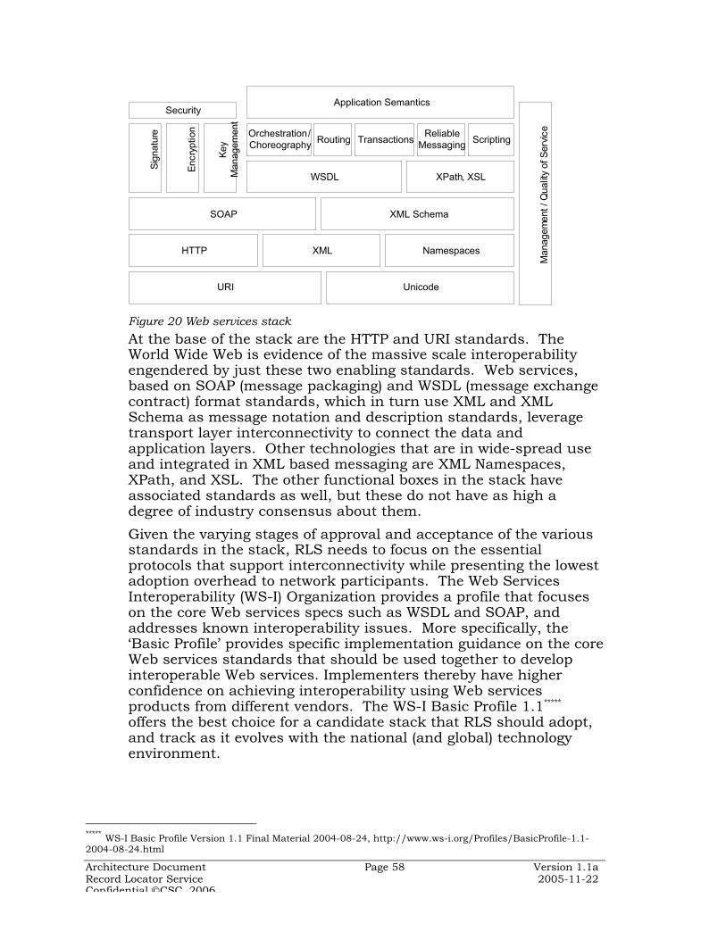
Architecture Document Page 58 Version 1.1aRecord Locator Service 2005-11-22Confidential CSC, 2006
HTTP XML Namespaces
UnicodeURI
SOAP XML Schema
WSDL XPath, XSL
Security
Sig
natu
re
Enc
rypt
ion
Key
M
anag
emen
t
TransactionsOrchestration / Choreography Scripting
Application Semantics
Man
agem
ent /
Qua
lity
o f S
e rvi
ce
RoutingReliable
Messaging
Figure 20 Web services stack
At the base of the stack are the HTTP and URI standards. TheWorld Wide Web is evidence of the massive scale interoperabilityengendered by just these two enabling standards. Web services,based on SOAP (message packaging) and WSDL (message exchangecontract) format standards, which in turn use XML and XMLSchema as message notation and description standards, leveragetransport layer interconnectivity to connect the data andapplication layers. Other technologies that are in wide-spread useand integrated in XML based messaging are XML Namespaces,XPath, and XSL. The other functional boxes in the stack haveassociated standards as well, but these do not have as high adegree of industry consensus about them.
Given the varying stages of approval and acceptance of the variousstandards in the stack, RLS needs to focus on the essentialprotocols that support interconnectivity while presenting the lowestadoption overhead to network participants. The Web ServicesInteroperability (WS-I) Organization provides a profile that focuseson the core Web services specs such as WSDL and SOAP, andaddresses known interoperability issues. More specifically, the‘Basic Profile’ provides specific implementation guidance on the coreWeb services standards that should be used together to developinteroperable Web services. Implementers thereby have higherconfidence on achieving interoperability using Web servicesproducts from different vendors. The WS-I Basic Profile 1.1*****
offers the best choice for a candidate stack that RLS should adopt,and track as it evolves with the national (and global) technologyenvironment.
***** WS-I Basic Profile Version 1.1 Final Material 2004-08-24, http://www.ws-i.org/Profiles/BasicProfile-1.1-2004-08-24.html

Architecture Document Page 59 Version 1.1aRecord Locator Service 2005-11-22Confidential CSC, 2006
In addition, WS-I has published a draft Basic Security Profile thatshould be used in implementing WS-Security based services.†††††
The advantages of using the WS-I profiles include reuse of tools,implementation guides, and reduced costs, complexity and risks. Amore restricted Web services stack with specifications that conformto the WS-I Basic Profile, is shown in Figure 21.
HTTP 1.1 XML 1.0 XML Namespaces 1.0
Unicode: UTF-8 / UTF-16URI: RFC 3986
SOAP 1.1 XML Schema 1.0
WSDL 1.1 XPath, XSL
SecurityX
ML
Sig
natu
re
XM
L E
ncry
ptio
n
XM
L K
ey
Man
agem
ent
TransactionsOrchestration / Choreography Scripting
Application Semantics
Man
agem
ent /
Qua
lity
of S
ervi
ce
RoutingReliable
Messaging
WS-I Basic Profile 1.1WS-I Basic Security Profile
Working Group Draft
SS
L 3.
0 / T
LS 1
.0
X.5
09: R
FC24
59
Figure 21 WS-I Basic Profile Web Services stack
RLS uses the WS-I Basic Profile as its core messaging and transportservices standards suite. Web services specifications providingstandard XML grammars for the other functions in the technologystack are growing and some (e.g. BPEL for process orchestration)are strong candidates to become mainstream standards in the nearterm.
As RLS grows functionally the appropriate specifications should bereviewed and incorporated into the standards stack. Ideally, thisevolution of RLS standards should leverage profiles developed byWS-I, or other interoperability standards organizations. WS-I iscurrently engaged in updating the Basic Profile to include SOAPv1.2 and WSDL v2.0 which offer significant functionalityimprovements over the current versions in the profile. RLSimplementations should develop migration strategies to SOAP v1.2and WSDL v2.0, so that the added benefits from the new featurescan be availed.
††††† WS-I Basic Security Profile Version 1.0 Working Group Draft 2005-08-29, http://www.ws-i.org/Profiles/BasicSecurityProfile-1.0-2005-08-29.html
Architecture Document Page 60 Version 1.1aRecord Locator Service 2005-11-22Confidential CSC, 2006
An alternate XML based business to business messagingframeworks with strong claims to being ‘industry standard’ isOASYS’ Electronic Business using eXtensible Markup Language(ebXML) framework‡‡‡‡‡. ebXML has been adopted by, among other,the U.S. Department of Defense for EMall, Center for DiseaseControl and Prevention (CDC) Public Health Information Network(PHIN), and NHS (UK) National Program for Information Technology(NPfIT). While the corresponding WS-* standards are maturing, asof this writing ebXML is clearly ahead in terms of stablespecifications for reliable messaging, security, and exceptionhandling. However, the rate of uptake of WS-* across the USmarket is higher than ebXML, particularly among applications andtools vendors. The perception that ebXML carries majorimplementation overhead has inhibited its use particularly amongsmaller organizations.
There are significant commonalities between the standardssuggested for RLS and the PHIN ebXML stack. ebXML wrapsanother envelope on a SOAP message, and there is overlap betweenWSDL and ebXML’s CPPA, as well as between UDDI and the ebXMLregistry. The RLS architecture is extensible to support ebXMLbased messaging, through extension of the Gateway IntegrationServices layer to include an ebMS type messaging adaptor.
6.6.2 Domain Data Standards
Having fixed on the Web services stack as its data transportstandards RLS offers significant flexibility in choice of domain datastandards. The primary use cases that RLS supports deal withpublishing and looking up patient demographic information. Theleading information model standard for patient information is theHL7 Reference Information Model (RIM), which is the basis for thenew HL7 v3 message formats definition. RLS uses the HL7 RIM asthe basis for data standards. RLS adopts a HL7 v3 message formatfor the various interactions it supports. Given the prevalence ofHL7 v2.x messaging in the healthcare industry in the US, RLS alsosupports a 2.4 (XML) based message format. Details are providedin the RLS Communication Messaging Implementation Guide.
In general information exchange between nodes in the healthcarenetwork may be visualized as occurring over a multi-layered set ofstandards, as shown in Figure 22.
‡‡‡‡‡ ebXML OASIS http://www.ebxml.org/

Architecture Document Page 61 Version 1.1aRecord Locator Service 2005-11-22Confidential CSC, 2006
Message
Data
Transport
Message
Data
Transport
Encrypted Message
XML
SOAP
HTTPS
Payload Packaging
Payload
Secure Message Transport
EHR information EHR informationHL7 v3(or alt)
Clinical Data
Figure 22 Interoperability Network Layers
EHR information in the RLS context refers specifically to patientdemographic and identifier information. The same stack isapplicable to general clinical data exchange in the healthcareinformation network. The domain data standards would be mostlydrawn from the available HL7 format standards. However, legacydata formats need to be catered to such as NCPDP Script forprescription medication data, and DICOM for radiology imaging.
The interoperability framework is focused on messaging and datastandards. This is in keeping with the SOA principle that interfacestrump implementation. The internal implementation details of theRLS Patient Index service or Gateway service are not relevant to theinteroperability of the different network nodes. The two interfacesinternal to a network node are:
¶ User access to the RLS is from standard Web-browser clients thatinvoke presentation services from the CDX Gateway servers. The userinterface is generated in strict XHTML so that enterprises can use CSSand XSL style sheets to customize the user experience as necessary.
¶ Gateway services interface with the local clinical data systems throughstandards interfaces such as HL7 messaging, or SQL databasequeries. If the Gateway is to serve as a clinical data cache to offloadqueries from the transaction clinical system, then data feeds need tobe built to move clinical data into the Gateway data cache.
6.6.3 Comprehensive Standards List
The full suite of standards covering support functions for RLSimplementation and use in the healthcare information network islisted in Table 7.
Table 7 List of StandardsComponent Specification CommentsHypertext Transport HTTP/1.1: RFC 3818 Base message transport
layered on TCP/IP
Directory access LDAP v3
Domain name services RFC 1035
Transport security SSL v3 / TLS 1.0
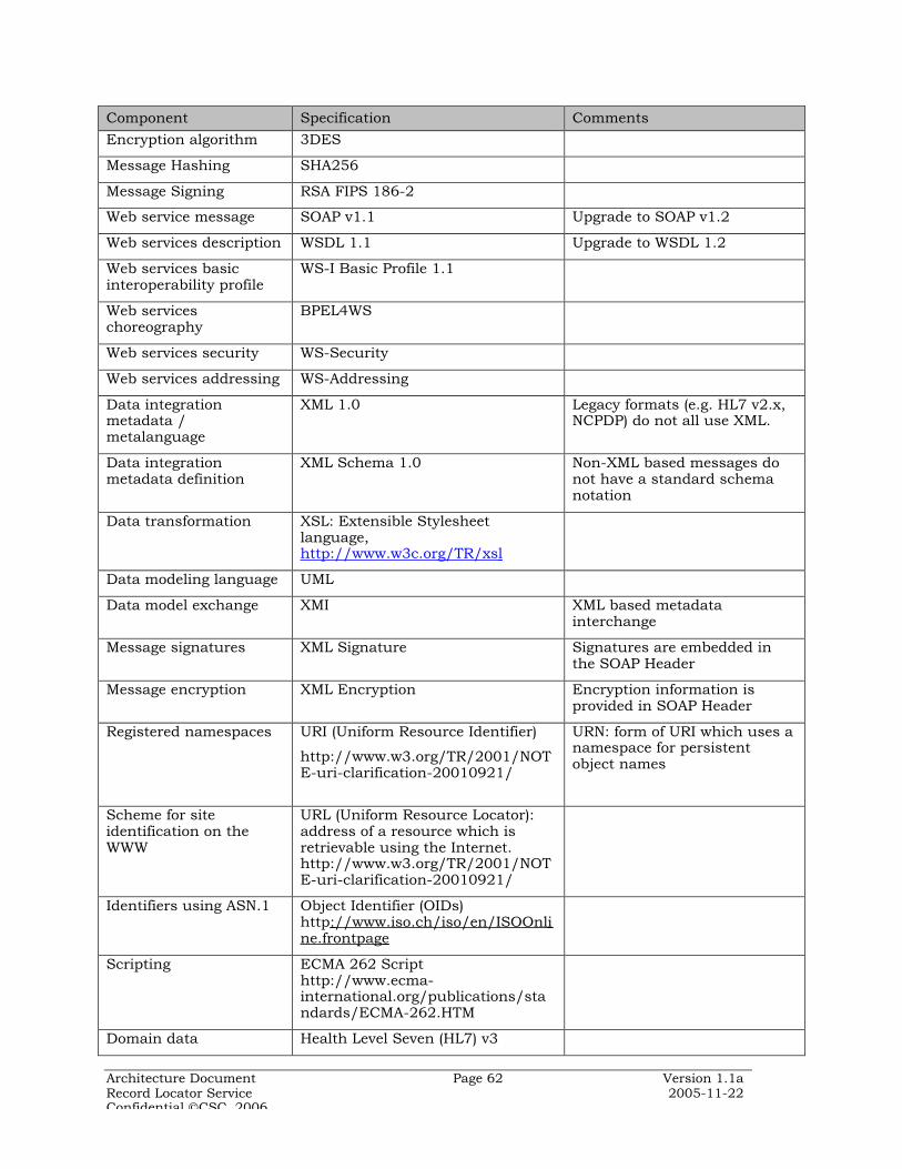
Architecture Document Page 62 Version 1.1aRecord Locator Service 2005-11-22Confidential CSC, 2006
Component Specification CommentsEncryption algorithm 3DES
Message Hashing SHA256
Message Signing RSA FIPS 186-2
Web service message SOAP v1.1 Upgrade to SOAP v1.2
Web services description WSDL 1.1 Upgrade to WSDL 1.2
Web services basicinteroperability profile
WS-I Basic Profile 1.1
Web serviceschoreography
BPEL4WS
Web services security WS-Security
Web services addressing WS-Addressing
Data integrationmetadata /metalanguage
XML 1.0 Legacy formats (e.g. HL7 v2.x,NCPDP) do not all use XML.
Data integrationmetadata definition
XML Schema 1.0 Non-XML based messages donot have a standard schemanotation
Data transformation XSL: Extensible Stylesheetlanguage,http://www.w3c.org/TR/xsl
Data modeling language UML
Data model exchange XMI XML based metadatainterchange
Message signatures XML Signature Signatures are embedded inthe SOAP Header
Message encryption XML Encryption Encryption information isprovided in SOAP Header
Registered namespaces URI (Uniform Resource Identifier)
http://www.w3.org/TR/2001/NOTE-uri-clarification-20010921/
URN: form of URI which uses anamespace for persistentobject names
Scheme for siteidentification on theWWW
URL (Uniform Resource Locator):address of a resource which isretrievable using the Internet.http://www.w3.org/TR/2001/NOTE-uri-clarification-20010921/
Identifiers using ASN.1 Object Identifier (OIDs)http ://www.iso.ch/iso/en/ISOOnli ne.frontpage
Scripting ECMA 262 Scripthttp://www.ecma-international.org/publications/standards/ECMA-262.HTM
Domain data Health Level Seven (HL7) v3

Architecture Document Page 63 Version 1.1aRecord Locator Service 2005-11-22Confidential CSC, 2006
Component Specification CommentsClinical Terminology SNOMED
Sponsor: NLM (sourced fromCollege of American Pathologists)
Clinical Terms creates a singleunified terminology tounderpin the development ofthe integrated electronicpatient record by providing anessential building block for acommon computerizedlanguage for use across theworld
Architecture Document Page 64 Version 1.1aRecord Locator Service 2005-11-22Confidential CSC, 2006
7 Deployment View
This section describes how the major components of the RLS logicalarchitecture are distributed across hardware nodes in a healthinformation network. Given that only the interface (inter-nodemessaging) specifications are expected to be consistent, deploymentof systems based on the RLS architecture could vary widely basedon local technology policies and preferences. This section providesdeployment related information, for general guidance.
RLS components and services are designed to be flexible and highlyconfigurable to enable deployment across a wide variety of sites.RLS requires the deployment of software on the following two typesof server nodes:
¶ RLS Patient Index server which hosts the database of pointers torecords in the clinical data sources, and routing information for eachof the Gateways.
¶ CDX Gateway server which hosts the middleware that mediates datatransfer from clinical data sources maintained at distributed locations(e.g. provider clinical systems, payer claims databases) and theInternet.
The RLS Patient Index is deployed at a central facility that providesrobust data center management capabilities. This represents theone new patient data location that the health information networkintroduces. It is essential that HIPAA rules be observed at the RLSdata center, much as they would in a covered entity.
Gateway servers are located within the circle of trust of the clinicalsystem, and are typically deployed at the edge of the enterprise ITinfrastructure zone in what is popularly known as the “DMZ”. Anapplication firewall separates the Internet accessible gateway serverfrom the internal network resources of the clinical enterprise. Onlyspecific and authorized messages from the gateway are allowed pastthis application firewall.
Depending on volume of message traffic and throughputrequirements, consideration may be given to deploying an ‘XMLfirewall’ that protects against malicious XML content based attacks.Such devices also feature XML processing capabilities, includingXML Encryption and XML Digital Signatures using X.509 digitalcertificates based public keys. Typically, XML processing inhardware would provide significantly higher message handlingperformance. However, XML-aware network infrastructure is anemerging product category, and organizations should ensure thatlock-in to proprietary features is avoided by insisting onconformance to open standards and verifying interoperability withXML software solutions.
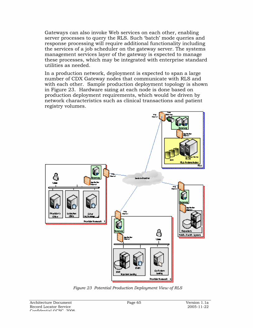
Architecture Document Page 65 Version 1.1aRecord Locator Service 2005-11-22Confidential CSC, 2006
Gateways can also invoke Web services on each other, enablingserver processes to query the RLS. Such ‘batch’ mode queries andresponse processing will require additional functionality includingthe services of a job scheduler on the gateway server. The systemsmanagement services layer of the gateway is expected to managethese processes, which may be integrated with enterprise standardutilities as needed.
In a production network, deployment is expected to span a largenumber of CDX Gateway nodes that communicate with RLS andwith each other. Sample production deployment topology is shownin Figure 23. Hardware sizing at each node is done based onproduction deployment requirements, which would be driven bynetwork characteristics such as clinical transactions and patientregistry volumes.
Figure 23 Potential Production Deployment View of RLS

Architecture Document Page 66 Version 1.1aRecord Locator Service 2005-11-22Confidential CSC, 2006
7.1 Services Management
Systems management is critical to RLS-based network operations.The CDX Gateway architecture provides for comprehensive messagelogging and auditing capability. The same logs could be readilyextended to support monitoring and reporting using simplescripting and system utilities. Several enterprise and networksystems management tools exist that can be deployed to managethe CDX Gateway within the enterprise network context. Gatewaysneed to be instrumented with the appropriate Simple NetworkManagement Protocol (SNMP) agents for this purpose.
A Web services systems management standard: OASIS WebServices Distributed Management is expected to gain ground in thenear future and advance SOA management using Web services.WSDM is based on SNMP and the Common Information Model andwould represent a natural evolution from current distributedmanagement standards to Web services based ones. The advantageof WSDM is that it uses Web service methods to manage distributedservices such as those proposed for the RLS-based healthinformation network, and therefore aligns well with the RLSarchitecture. Additional system management services would needto be added to the CDX Gateways to monitor and control messagetraffic using the WSDM protocol.
One of the key features of WSDM is SOAP based deployment of Webservices. This would allow the Gateways to be deployed andconfigured from a central location (such as from RLS). This wouldfurther the goal of a utility service that can be cloned and deployedat the distributed network nodes with minimal disruption to theEHR systems at the node.
7.2 Security Services
Since RLS’ major communication security functionality isembedded in the gateway, this offers a convenient approach tolocalizing the deployment and management of security services.The major security infrastructure that needs to be deployed withthe RLS and CDX Gateways are the Digital Certificates required tosupport SSL and, in future, WS-Security.
Directory services (LDAP or Active Directory) are often used ascertificate stores, and as the user identity and roles repository.Enterprises directories should be used if this shared service isavailable on the EHR network. Gateways should be interfaced withthe enterprise directory using LDAP interfaces.
The reader is referred to directory and PKI documentation fordetailed guidance on the deployment and management of publickey certificates.

Architecture Document Page 67 Version 1.1aRecord Locator Service 2005-11-22Confidential CSC, 2006
8 Data View
Following the federated data architecture principle, RLS persistsminimal patient data centrally. The core of the RLS data store is acommunity Master Patient Index (CMPI) that supports lookup ofpatient electronic health record locations based on basicdemographic attributes.
A canonical information model is used to develop reference XMLschema that CDX Gateways use to send and receive messagesbased on the HL7 Reference Information Model§§§§§ (RIM). A logicaldata model using standard Entity-Relationship diagrammingnotation is derived from the information model. All messagingservices that RLS supports are integrated with the physicalimplementation of the logical model in the form of a relationaldatabase.
8.1 CMPI Information Model
The RLS information model view derived from the HL7 RIM isshown in Figure 24 for reference.
§§§§§ HL7 Reference Information Model, http://www.hl7.org/Library/data-model/RIM/modelpage_mem.htm ,2005-02-15
Person
providerOrganization
patientEncounter
clinicalAct
Observation
DiagnosticImage
SubstanceAdministration Procedure
1
*
1
*
1
*
-id[1..*] : II-assigningOrgID [1] : II-name [1..*] : EN-adminstrativeGenderCode [1]-birthTime [1]-effectiveTime [1] : IVL-statusCode [1] : CV-addr [0..*] : AD-telecom [0..*] : TEL-raceCode [0..*] : CV-ethnicGroupCode [0..*] : CE-religiousAffiliationCode [0..1] : CE-deceasedInd [0..1] : BL-deceasedTime [0..1] : TS-multipleBirthInd [0..1] : BL-multipleBirthOrderNumber [0..1] : INT-maritalStatusCode [0..1] : CE-languageCode [0..1] : CV-otherIDs [0..*] : II-otherNames [0..*] : EN
communityMasterPatientIndex
* *
-root-extension-assigningAuthorityName-displayable
«type» II
-delimiter-houseNumberNumeric-houseNumber-streetAddressLine-streetName-streetNameBase-streetNameType-city-postalCode-county-state-country-additionalLocator-unitID-unitType-carrier-censusTract-usablePeriod
«type»AD
-given-family-prefix-suffix
«type»EN
*
*
**
**
**
-codeSystem-code-codeSystemName-codeSystemVersion-displayName
«type»CV
*
*
Figure 24 Information Model View

Architecture Document Page 68 Version 1.1aRecord Locator Service 2005-11-22Confidential CSC, 2006
The community Master Patient Index follows the traditional MPIstructure storing only ‘pointers’ to providers systems and patientidentifiers therein, in addition to essential demographics attributesthat can be searched on. The pointer to patient records is the idattribute of the communityMasterPatientIndex (CMPI) class. Thelist of attributes shown in the model view represents a set of allpossible patient demographics. An RLS implementation wouldchoose a specific subset of demographic attributes for the CMPIbased on the specific community policies and requirements.
As can be seen from the information model, the patient EHR thatthe RLS index points to is a hierarchical abstraction of the RIMclasses. With the patient index provided by the CMPI users canretrieve and select from visits or patient encounters at the providerfacility. Users may then navigate from encounters to individualcare records represented by the generalized clinical act class thatmay refer to procedures, observations (covering laboratory results,diagnostic images, etc.) and substanceAdministration (medication)lists.
8.2 Logical Data Model
The classes and attributes in the RLS information model aretranslated into entities and attributes of a logical data model thatcan be implemented physically in a relational (SQL) DBMS. Thelogical data model derived from the information model is shown inFigure 25.
The Entity-Relationship (ER) modeling notation used here is directlytranslatable to physical SQL databases. Entities have attributescorresponding to the class attributes of the information model.Attributes above the dividing line form the ‘primary key’ of theentity. Relationships between entities are denoted with lines thathave a crows-foot notation to symbolize the ‘many’ end of a one-to-many relationship. These relationships result in the entity at the‘many’ end inheriting the primary key of the entity at the ‘one’ end,as a foreign key marked as (FK).
The identifiedPerson entity represents the person as maintained inthe source (EHR) system. The attributes of the CMPI entity showndo not signify the norm in any way. Select attributes from theidentifiedPerson entity are replicated into the CMPI entity, based oncommunity requirements for patient record matching. Theidentifying information (primary key) of patients in thecommunityMasterPatientIndex (CMPI) is formed by concatenatingthe identifiers of the assigningOrganization and theidentifiedPerson. This combination of identifiers provides a uniquekey for the CMPI record.
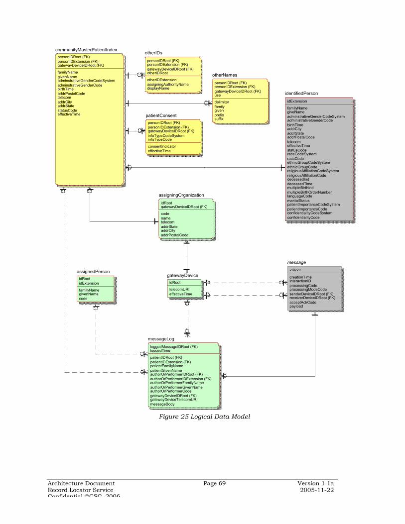
Architecture Document Page 69 Version 1.1aRecord Locator Service 2005-11-22Confidential CSC, 2006
communityMasterPatientIndex
personIDRoot (FK)personIDExtension (FK)gatewayDeviceIDRoot (FK)
familyNamegivenNameadminstrativeGenderCodeSystemadminstrativeGenderCodebirthTimeaddrPostalCodetelecomaddrCityaddrStatestatusCodeeffectiveTime
otherNames
personIDRoot (FK)personIDExtension (FK)gatewayDeviceIDRoot (FK)use
delimiterfamilygivenprefixsuffix
otherIDs
personIDRoot (FK)personIDExtension (FK)gatewayDeviceIDRoot (FK)otherIDRoot
otherIDExtensionassigningAuthorityNamedisplayName
messageLog
loggedMessageIDRoot (FK)loggedTime
patientIDRoot (FK)patientIDExtension (FK)patientFamilyNamepatientGivenNameauthorOrPerformerIDRoot (FK)authorOrPerformerIDExtension (FK)authorOrPerformerFamilyNameauthorOrPerformerGivenNameauthorOrPerformerCodegatewayDeviceIDRoot (FK)gatewayDeviceTelecomURImessageBody
assignedPerson
idRootidExtension
familyNamegivenNamecode
gatewayDevice
idRoot
telecomURIeffectiveTime
message
idRoot
creationTimeinteractionIDprocessingCodeprocessingModeCodesenderDeviceIDRoot (FK)receiverDeviceIDRoot (FK)acceptAckCodepayload
assigningOrganization
idRootgatewayDeviceIDRoot (FK)
codenametelecomaddrStateaddrCityaddrPostalCode
identifiedPerson
idExtension
familyNamegiveNameadminstrativeGenderCodeSystemadministrativeGenderCodebirthTimeaddrCityaddrStateaddrPostalCodetelecomeffectiveTimestatusCoderaceCodeSystemraceCodeethnicGroupCodeSystemethnicGroupCodereligiousAffiliationCodeSystemreligiousAffiliationCodedeceasedInddeceasedTimemultipleBirthIndmultipleBirthOrderNumberlanguageCodemaritalStatuspatientImportanceCodeSystempatientImportanceCodeconfidentialityCodeSystemconfidentialityCode
patientConsent
personIDRoot (FK)personIDExtension (FK)gatewayDeviceIDRoot (FK)infoTypeCodeSysteminfoTypeCode
consentIndicatoreffectiveTime
Figure 25 Logical Data Model
Architecture Document Page 70 Version 1.1aRecord Locator Service 2005-11-22Confidential CSC, 2006
Within a clinical data source, patients are usually assigned localidentifiers (e.g. MRN, chart number, etc.). In some instancesalternate standard identifiers (e.g. Social Security Number,Medicaid numbers etc.) are used. Given the expected variability indata quality in diverse clinical systems, and the privacy constraintsaround some of the standard identifiers used (such as SSN) RLSdoes not distinguish between these two types of identifiers. Each istreated as a non-intelligent key to the patient record in the clinicaldata source.
The gatewayDevice entity is used to store the network address ofthe clinical data source managed by the assigningOrganization.Thus, along with the patient pointer information the CMPI returnsthe network address (of the Gateway) to which queries for patientmedical records should be sent. When an EHR Gateway receives apatient medical data request it resolves the medical record locationusing the personIDRoot (assigningOrganization’s ID) part of thepatient index, and redirects the query to the appropriate clinicaldata source.
The RLS supports use of multiple other identifiers for a patientsuch as identifiers used by ancillary systems. Theses additionalidentifiers are used more as attributes than identifiers, and may beused to search for the patient in the RLS. Standard identifiers, e.g.SSN, may be explicitly used as otherIDs, if the RLS implementationpolicy and regulations permit. The otherIDRoot attribute entityrepresents organizations such as the Social Security Administration(for SSN) or state Registry of Motor Vehicles (for driver’s licenses).
The assignedPerson entity represents the user who has access tothe gatewayDevice. The user role that determines access rights ofthe user is carried in the ‘code’ attribute (following the HL7 v3implementation guide).
In addition to the business domain entities, messages and messagelogs are represented in the model. Messages are not storedphysically in the RLS database except as XML strings in themessage logs. Message logs are generic entities that may be usedto store all messages that flow through the RLS/Gateway. Thisentity also carries patient and user attributes related to themessage, which supports auditing of the logs.
8.2.1 Identifier Attributes
Translation from the object-oriented information model to classicrelational data structures requires that the HL7 v3 data types beconverted to SQL data types. The conversion is for the most partstraight-forward where the components of the object attribute typessuch as II, EN, AD, etc. are flattened out to sequences of SQL datatypes.
Architecture Document Page 71 Version 1.1aRecord Locator Service 2005-11-22Confidential CSC, 2006
Identifiers in the logical data model are formed from HL7 v3instance identifiers (type II), and are worth examining in more detailsince they are critical to understanding of the data returned byRLS. The II data type is defined as******:
An identifier that uniquely identifies a thing or object. Examples are object identifier for HL7 RIMobjects, medical record number, order id, service catalog item id, Vehicle Identification Number(VIN), etc. Instance identifiers are defined based on ISO object identifiers.
Instance identifiers are used for patient, organizations, devices etc.The HL7 v3 data type II has the following structure:Element Description
root A unique identifier that guarantees the global uniqueness ofthe instance identifier. The root alone may be the entireinstance identifier. This is number sequence that matchesa pattern corresponding to DCE UUID, ISO OID, or stringsconsisting only of (US-ASCII) letters, digits and hyphens,where the first character must be a letter
extension A character string as a unique identifier within the scope ofthe identifier root. If the root is used as a unique identifier,the extension is null
assigningAuthority A human readable name or mnemonic for the assigningauthority. Note: no automated processing must depend onthe assigning authority name to be present in any form.
displayable Specifies if the identifier is intended for human display anddata entry (displayable = true) as opposed to pure machineinteroperation (displayable = false).
The extension, assigningAuthority, and displayable attributes are alloptional. The root may itself be used as a unique identifier, such aswhen it contains a UUID. In the RLS data model, the convention isto use UUIDs for transactional entities such as messages. Entitiessuch as organizations and devices have fixed identifiers set up bythe RLS, which may use OIDs or UUIDs. Patients have two partidentifiers, where the root maps to the assigningOrganization’s idand the extension to the specific person id (e.g. MRN).
The root attribute of the patient identifier is set to the OID or UUIDof the ‘assigningOrganization’ that defines the id namespace (withinwhich the id is unique). The personIDRoot of the CMPI is a foreignkey mapping to the assigningOrganization primary key idRoot andthe personIDExtension maps to the identifiedPerson primary keyidExtension. The personIDRoot may be considered the prefix thatRLS attaches to make the pointer unique in the CMPI.
****** HL7 v3 Standard, Data Types Abstract Specification, September 2005

Architecture Document Page 72 Version 1.1aRecord Locator Service 2005-11-22Confidential CSC, 2006
The primary key of the CMPI is not used for searching as thedemographics attributes are. Searchable identifiers are stored inthe otherIDs entity. For example, when a user specifies, wherepermitted, the SSN of the patient as a query criterion, the RLSderives the OID of the SSA using a lookup table of standard OIDs,which is then used to match the patientIDRoot of the otherIDs tableand the given SSN is matched to the patientIDExtension.
8.3 Physical Data Model
The physical data model maps very closely to the logical modelshown above. However, the physical tables are not all implementedin the same database instance since the architecture posits the RLSas a combination of a Patient Index service and a distributedGateway service. The distribution of tables across the Patient Indexand the Gateway is worth further discussion. The problem of OIDsmanagement is also relevant to this design discussion.
The tables generated from the CMPI, patientConsent, otherIDs andotherNames entities reside in the Patient Index database. Inaddition the patient matching algorithm may create persistentsecondary indexes to increase the performance of lookup queries.For example a probabilistic matching method may need to maintaina secondary index of Soundex transformed names. Since the RLSarchitecture needs to work with multiple matching algorithms, thepatient matching component is treated as a separate service thatmaintains all the secondary indexes it needs. Optionally, the recordmatching algorithm may also generate a linking identifier thatwould be persisted along with the index. However, this would leadto increased maintenance overheads.
The remaining tables in the logical data model are created in theGateway service data storage layer. Authorized user identity(assignedPerson) and messageLog tables are used for the purposesdescribed above at Gateway services at each node in the healthcareinformation network, including the RLS node.
Organization and gateway information is maintained at each nodebased on the message processing requirements at the node. TheRLS maintains the master list of Gateway services at all thenetwork nodes. The Gateway service at the participating nodesmaintains information on the various clinical data sources that itsupports. The RLS does not require to know the details of theindividual clinical data sources at each node. That information isabstracted by the Gateway service at that node. The RLS maintainsa local copy of the OIDs for standard identifier assigning authoritiesas replicated from centrally maintained registries, e.g. the HL7 OIDregistry.
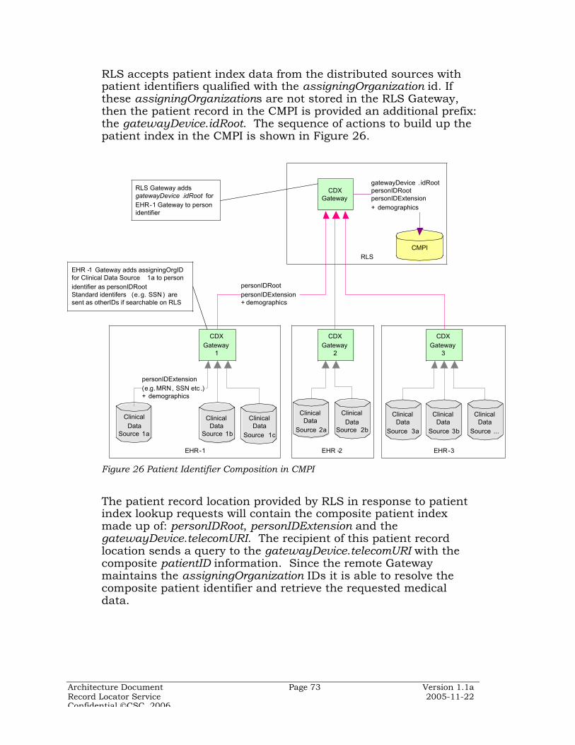
Architecture Document Page 73 Version 1.1aRecord Locator Service 2005-11-22Confidential CSC, 2006
RLS accepts patient index data from the distributed sources withpatient identifiers qualified with the assigningOrganization id. Ifthese assigningOrganizations are not stored in the RLS Gateway,then the patient record in the CMPI is provided an additional prefix:the gatewayDevice.idRoot. The sequence of actions to build up thepatient index in the CMPI is shown in Figure 26.
EHR-1
RLS
ClinicalData
Source 1a
CMPI
personIDRootpersonIDExtension+ demographics
personIDExtension (e.g.MRN, SSN etc .)+ demographics
CDX Gateway
CDX Gateway
1
gatewayDevice . idRootpersonIDRootpersonIDExtension+ demographics
EHR -1 Gateway adds assigningOrgID for Clinical Data Source 1a to person identifier as personIDRoot Standard identifers (e.g. SSN ) are sent as otherIDs if searchable on RLS
RLS Gateway adds gatewayDevice .idRoot for EHR-1 Gateway to person identifier
EHR -2
CDX Gateway
2
EHR-3
CDX Gateway
3
ClinicalData
Source 1b
ClinicalData
Source 1c
ClinicalData
Source 2a
ClinicalData
Source 2b
ClinicalData
Source 3a
ClinicalData
Source 3b
ClinicalData
Source ...
Figure 26 Patient Identifier Composition in CMPI
The patient record location provided by RLS in response to patientindex lookup requests will contain the composite patient indexmade up of: personIDRoot, personIDExtension and thegatewayDevice.telecomURI. The recipient of this patient recordlocation sends a query to the gatewayDevice.telecomURI with thecomposite patientID information. Since the remote Gatewaymaintains the assigningOrganization IDs it is able to resolve thecomposite patient identifier and retrieve the requested medicaldata.
Architecture Document Page 74 Version 1.1aRecord Locator Service 2005-11-22Confidential CSC, 2006
As the above discussion shows, the division of labor between theGateways at the clinical data source and the RLS requires that theappropriate cross-reference tables be maintained accordingly. Atthe RLS the various remote Gateways are assigned OIDs andmaintained in the gatewayDevice table. The Gateway at the clinicaldata source, in turn, assigns OIDs to each clinical data source andmaintains the cross-reference in the assigningOrg table. The use ofOIDs is not mandatory; any local identifier system may be used aslong as the patient identifier composition process described above isfollowed.
8.3.1 Data Quality Management
A general principle is that the CMPI database be a read-only versionof patient records as they exist on source systems. The CMPI isintended purely for record matching and is not to be considered apatient registry. Data quality issues are expected to be resolved onthe source systems, and cleansed data would replicate to the CMPI.The CMPI is therefore different from an Enterprise MPI in that nocentral data management organization is envisaged for an RLS.Data cleansing and quality services are not thought to be viable in acommunity of disparate, autonomous enterprises contributing datainto the CMPI.
8.3.2 Data Cache
Message caching (logging) is likely to be required (over and beyondthe persistence service offered by the MQ engine)
The data services layer in the CDX Gateway could serve as a cachefor patient EHR data. Alternate architectures use clinical datarepositories at the edge to serve the data requests received viainformation exchanges, so that core clinical data sources are not hitby these queries that could potentially impact the core clinicalsystem performance. This aspect is discussed in more detail inSection 6.3. Some nodes may not want to push their EHR directlyto the CMPI, instead may choose to expose their EMPI, or replicatetheir MPIs to the CMPI. Replicated MPI should have a ‘time-to-live’based expiry, after which it must be refreshed.
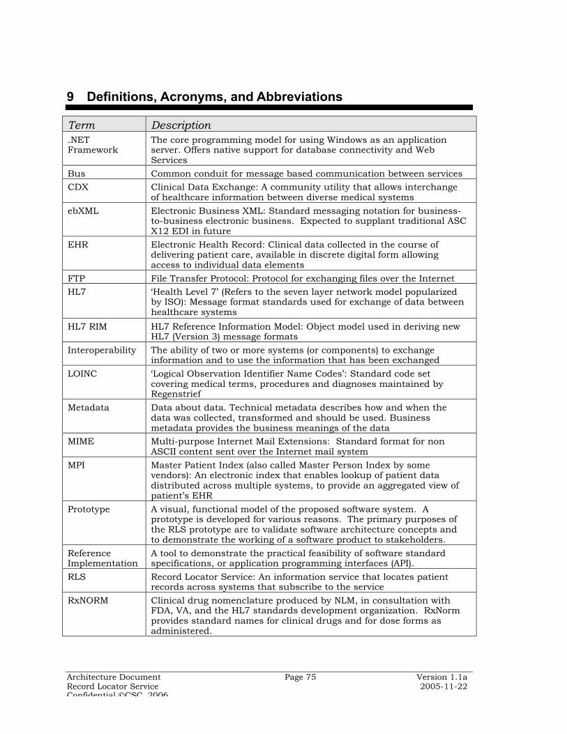
Architecture Document Page 75 Version 1.1aRecord Locator Service 2005-11-22Confidential CSC, 2006
9 Definitions, Acronyms, and Abbreviations
Term Description.NETFramework
The core programming model for using Windows as an applicationserver. Offers native support for database connectivity and WebServices
Bus Common conduit for message based communication between servicesCDX Clinical Data Exchange: A community utility that allows interchange
of healthcare information between diverse medical systemsebXML Electronic Business XML: Standard messaging notation for business-
to-business electronic business. Expected to supplant traditional ASCX12 EDI in future
EHR Electronic Health Record: Clinical data collected in the course ofdelivering patient care, available in discrete digital form allowingaccess to individual data elements
FTP File Transfer Protocol: Protocol for exchanging files over the InternetHL7 ‘Health Level 7’ (Refers to the seven layer network model popularized
by ISO): Message format standards used for exchange of data betweenhealthcare systems
HL7 RIM HL7 Reference Information Model: Object model used in deriving newHL7 (Version 3) message formats
Interoperability The ability of two or more systems (or components) to exchangeinformation and to use the information that has been exchanged
LOINC ‘Logical Observation Identifier Name Codes’: Standard code setcovering medical terms, procedures and diagnoses maintained byRegenstrief
Metadata Data about data. Technical metadata describes how and when thedata was collected, transformed and should be used. Businessmetadata provides the business meanings of the data
MIME Multi-purpose Internet Mail Extensions: Standard format for nonASCII content sent over the Internet mail system
MPI Master Patient Index (also called Master Person Index by somevendors): An electronic index that enables lookup of patient datadistributed across multiple systems, to provide an aggregated view ofpatient’s EHR
Prototype A visual, functional model of the proposed software system. Aprototype is developed for various reasons. The primary purposes ofthe RLS prototype are to validate software architecture concepts andto demonstrate the working of a software product to stakeholders.
ReferenceImplementation
A tool to demonstrate the practical feasibility of software standardspecifications, or application programming interfaces (API).
RLS Record Locator Service: An information service that locates patientrecords across systems that subscribe to the service
RxNORM Clinical drug nomenclature produced by NLM, in consultation withFDA, VA, and the HL7 standards development organization. RxNormprovides standard names for clinical drugs and for dose forms asadministered.

Architecture Document Page 76 Version 1.1aRecord Locator Service 2005-11-22Confidential CSC, 2006
Term DescriptionSAML Security Assertions Markup Language: An XML framework for
communicating security information (authentication, authorization,other attributes) between systems. SAML is independent of thesecurity protocol used (e.g. PKI, LDAP, Kerberos, etc.) and promotesinteroperability between disparate systems
SemanticInteroperability
Property of data exchange that ensures that the receiver of dataunderstands what the sender ‘meant’ (contrast with mere ‘syntactic’interoperability)
Service Application system with a standard network callable interface.ServiceOrientedArchitecture
An application architecture comprising components, whose interfacedescriptions can be published, discovered and invoked. Componentsare said to be loosely coupled in that they have no knowledge of eachother except for their respective interfaces and communicate witheach other through messagesW3C definition: A set of components which can be invoked, and whoseinterface descriptions can be published and discovered
S/MIME Secure MIME: Version of the basic MIME protocol that supportsencrypted messages based on RSA’s public key encryption technology
SNOMED-CT Systematized Nomenclature of Medicine – Clinical Terms: Standardcode set covering medical terms, procedures and diagnosesmaintained by College of American Pathologists
SOAP Acronym, originally, for Simple Object Access Protocol; no longerconsidered an acronym. Lightweight XML based protocol forexchanging information in Web service based implementations.Primarily specifies the XML ‘envelope’ for a message.
SSL Secure Sockets Layer: Protocol used to communicate private(encrypted) data over the Internet
UDDI Universal Description, Discovery and Integration: Mechanism for webservice providers to advertise services and consumers of services tolocate them.
UML Unified Modeling Language: general purpose language for specifyingand visualizing software systems. Favored for object-oriented softwaredevelopment
URI Universal Resource Identifier: The standard for naming andaddressing resources on the Internet. The commonly known URL(Universal Resource Locator) is a form of URI
VocabularyDomain
HL7 term for standardized set of values for coded attributes used inhealthcare information messages; e.g. ObservationMethod, Race,VaccineType
Web Services An application that is identified by an URI, and invoked via theInternet, using data exchange notations based on XML. Byemphasizing simplicity and open standards, disparate applicationscan securely interoperate without knowing internal details of eachother.W3C definition: “A Web service is a software system identified by aURI [RFC 2396], whose public interfaces and bindings are defined anddescribed using XML. Its definition can be discovered by othersoftware systems. These systems may then interact with the Webservice in a manner prescribed by its definition, using XML basedmessages conveyed by Internet protocols”

Architecture Document Page 77 Version 1.1aRecord Locator Service 2005-11-22Confidential CSC, 2006
Term DescriptionWSDL Web Services Description Language: standard XML based
specification to describe the interface to a Web Service. Machine-interpretable standard form for describing the operation of a webservice, represents the ‘contract’ that the Web Service honors with anyrequestor
WS-Security Specification that encompasses all XML security standards related toSOAP messaging. Covers how security tokens are to be generated forSOAP message headers, how XML messages are signed and encrypted,etc.
XML eXtensible Markup Language: Common notation used to representdata sent from one system to another. XML data files (or messages)use clear text and are ‘self-describing’ enabling human as well asmachine understanding. E.g. HTML notation is based (loosely) onXML.


![[MS-TAIL]: Telephony API Internet Locator Service Protocol... · Telephony API Internet Locator Service Protocol Dynamic Directory Object Internet Locator Service (ILS). people. .](https://static.fdocuments.net/doc/165x107/5f3d1ee4f10ab21c51753c36/ms-tail-telephony-api-internet-locator-service-protocol-telephony-api-internet.jpg)