Programming DCC Locomotives with JMRI - DCC Geek DCC Locomotives with JMRI.pdf · Configure: Hornby...
64
PROGRAMMING DCC LOCOMOTIVES WITH JMRI Carl Marchand NMRA Prototype Rails 2018 Cocoa Beach, FL
Transcript of Programming DCC Locomotives with JMRI - DCC Geek DCC Locomotives with JMRI.pdf · Configure: Hornby...

PROGRAMMING DCC LOCOMOTIVES WITH JMRI
Carl Marchand
NMRA Prototype Rails 2018
Cocoa Beach, FL

MATERIALS AND HANDOUTS
http://www.dccgeek.com/downloads.html

WHAT IS JMRI?
• JMRI stands for Java Model Railroad Interface
• JMRI is an open source program for model railroad hobbyists
• JMRI is a Program Suite, consisting of:
• DecoderPro® - A better tool for programming decoders, simplifying the job of configuring DCC
decoders from your computer
• PanelPro™ - Design and Operate CRT based CTC control panels that reflect the real-time state of
your railroad and let you control it
• DispatcherPro - A system for Dispatching, grouping your Roster and Throttles
• OperationsPro™ - Build Trains from your Roster and print Train Manifests that detail the work your
train crews will perform
• AudioPro - A set of tools for using Audio with JMRI

TO USE JMRI YOU’LL NEED:
• A COMPUTER RUNNING WINDOWS, OR LINUX (VARIOUS TYPES ARE
SUPPORTED)
• JAVA
• A DCC SYSTEM OR A SPROG (HTTP://WWW.RR-CIRKITS.COM)
• A COMPUTER INTERFACE FOR YOUR DCC SYSTEM

WHERE TO GET JMRI SOFTWARE?
• Go to: http://jmri.sourceforge.net

SUPPORTED HARDWARE
Atlas (XPressNet)
Configure: Atlas Commander via Lenz LI100, LI101F, LIUSB or GenLi XPressNet interfaces, ZTC Controls ZTC640 interface, or an XPA and Hayes compatible modem
Note: you can not program decoders with this configuration.
Bachrus
Configure: Bachrus MTS-DCC Model Train Speedometer
C/MRI C/MRI
Configure: Bruce Chubb's C/MRI control system for a connection via direct serial, USB-serial adapter, or network connection.
CTI Electronics Acela Configure: CTI Electronics boards

SUPPORTED HARDWARE
CVP Products EasyDCC
Configure: EasyDCC command station via Serial or Terminal Server
DCC++
Configure: DCC++ Open Source Arduino Command Station.
DCC Specialties
Configure: Hare, Wabbit, Block Watcher or PSX family products.
Digi
General information on connecting to a Digi XBee network

SUPPORTED HARDWARE
Digitrax
General information on connecting JMRI to a Digitrax LocoNet
Configure: Connections to a LocoNet via
Digitrax PR3 interface RR-CirKits LocoBuffer-USB The older LocoBuffer-II, LocoBuffer and MS100 interfaces Bluetooth LocoBridge
Configure: LocoNet Simulator for use when disconnected from a layout.
Configure: Remote connection to a LocoNet via JMRI LocoNet Server.
Configure: Remote connection to a LocoNet via LbServer.
More information on connecting multiple computers to a single LocoNet
Configure: Programming and testing decoders without a command station via a Digitrax PR2 interface or PR3 interface.
Configure: Directly connecting to an Intellibox.
ESU
Configure connection to ECoS command station.

SUPPORTED HARDWARE
Fleischmann
Configure: Twin Centre communications (LocoNet)
Hornby
Configure: Hornby Elite via built in USB Port
Configure: Hornby Elite or Hornby Select via Lenz LI100, LI101F, LIUSB or GenLi XPressNet interfaces, ZTC Controls ZTC640 interface, or an XPA and Hayes compatible modem.
Please check the notes above for system specific restrictions on what JMRI can do.
Lenz
Configure: Lenz LI100, LI101F, LIUSB or GenLi XPressNet interfaces, ZTC Controls ZTC640 interface, or an XPA and Hayes compatible modem.
Please check the notes above for system specific restrictions on what JMRI can do.
Lionel TMCC
Connection: Serial cable
Configure: TMCC Command Base

SUPPORTED HARDWARE
Maple Systems
Maple Systems touch panel
Configure: connection via serial link
Märklin
Configure connection to CS2 Command Station 2.
CS Command Station - see ESU ECoS
MERG CBUS
Configure: MERG CBUS networks
Modbus
Configure: Modbus networks
Model Rectifier Corp (MRC)

SUPPORTED HARDWARE
NAC Services RPS
Configure connection to an RPS position detection system.
NCE
Configure connection to a Powerhouse Pro via serial link or Terminal Server. Configure connection to a PowerCab via NCE USB adapter.
Oak Tree Systems
Configure connection to Oak Tree's Railroad Control Interface (RCI), including the IO-24, IO-48 and O-48 interface cards and HH-2 handheld throttle. (Note: RCI is to be replaced by Layout Control System (LCS))
OpenLCB
Configure: OpenLCB networks
ProTrak Grapevine
Configure: Grapevine nodes

SUPPORTED HARDWARE
QSI Solutions
Connection: Quantum Programmer
Configure: USB connection
QSI decoders can be programmed with DecoderPro through any DCC system. JMRI can't load sounds into QSI decoders.
RailDriver PI Engineering RailDriver
Configure: RailDriver cab simulator
Raspberry Pi Foundation
General information on connecting to the Raspberry PI GPIO pins.
Roco (XPressNet)
Configure: Roco LocoMaus 2 (Roco Part number 10760), Roco MultiMaus (Roco Part number 10810), or Roco multiZENTRAL-Pro (Roco Part number 10830) via Lenz LI100, LI101F, LIUSB or GenLi XPressNet interfaces, ZTC Controls ZTC640 interface, or an XPA and Hayes compatible modem.
Please check the notes above for system specific restrictions on what JMRI can do.

SUPPORTED HARDWARE
SPROG
Configure: SPROG as either a stand-alone DCC programmer or DCC command station
SRCP
Configure: Connection to SRCP server
TAMS
Configure connection to TAMS Master Control command station.
Uhlenbrock
The Intellibox can be connected to JMRI programs either via a LocoNet connection, or via its own built-in serial (RS232) port or USB connection.
Configure: Uhlenbrock Intellibox-I or -II via LocoNet interface
Configure: Uhlenbrock Intellibox-I via built-in serial port
Configure: Uhlenbrock Intellibox-II via built-in USB connection
Configure: System One
SUPPORTED HARDWARE
Viessmann (XPressNet) Configure: Viessmann Commander via Lenz LI100, LI101F, LIUSB or GenLi XPressNet interfaces, ZTC Controls ZTC640 interface, or an XPA and Hayes compatible modem.
Please check the notes above for system specific restrictions on what JMRI can do.
Wangrow Wangrow
Connection: Wangrow Serial Port
X10 X10
Connection: X10, Insteon power-line controllers
Configure: CM11, 2412S and compatible controllers.

SUPPORTED HARDWARE
ZIMO
Configure: ZIMO MX-1
ZTC Controls (XPressNet)
Configure: ZTC Controls ZTC511, ZTC Controls ZTC521 via Lenz LI100, LI101F, LIUSB or GenLi XPressNet interfaces, ZTC Controls ZTC640 interface, or an XPA and Hayes compatible modem (requires XPressNet V3.0 software).
Please check the notes above for system specific restrictions on what JMRI can and cannot do.

COMMON DCC PROGRAMMING TERMS
• CV – Configuration Variable: DCC Decoder settings for motor control,
lighting effects, consisting controls and sound effects (a cv is something you
can adjust – a setting)
• Address: the DCC decoder’s ID number. To access the locomotive /mobile
decoder, you enter the address in the DCC throttle / system
• Service Mode Programming: programming with feedback /
acknowledgement from the decoder. This is done on a isolated programming
track. This is address- independent
• OPS Mode Programming: programming on the MAIN LINE track; no
feedback is available to the programming software / hardware. OPS mode
programming requires accessing the locomotive /mobile decoder via the
decoder’s ADDRESS.

SOME RECOMMENDATIONS
• Test Track – setup a loop of track 22” minimum radius if you do not have
a layout; higher if needed
• Separate / Isolated Programming Track – use this section of track for
PAGE mode and DIRECT mode programming
• Locomotive Roster Database ? USE JMRI DecoderPro! – DecoderPro’s
database makes a great roster database (we’ll show how)
• Purchase a decoder tester – test and configure your decoder before you
install it in your locomotive or rolling stock
• Join DCC Yahoo Groups – lots of help and documents on DCC and
Programming

DECODER TESTERS
NCE
ESU TCS

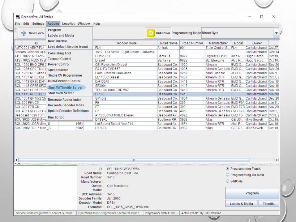
LETS GET STARTED:

Your Locomotive Roster
Use typically Direct Byte or Paged
Roster Photo

PAGED VS DIRECT MODE PROGRAMMING
PAGED MODE
• Paged Mode introduced the term "CV" (Configuration Variable).
• It is very slow when reading back the CVs.
• To read a CV, a number is sent to the decoder. If the response is negative, the number is
incremented by one, and the process repeats until a positive response is received from the
decoder. This process can repeat up to 256 times.
• Reading the complete CV set of a decoder will take a long time. Every CV will be tested
sequentially in this manner.
DIRECT MODE
• The popularity of Direct Mode is increasing all the time. It is a very fast mode of
programming. The NMRA would like to replace Paged Mode programming with Direct
Mode.
• Faster Readback of CVs
• Instead of asking "Is it 1?, Is it 2?", Direct Mode takes a different approach.
• It asks if Bit 1 of the CV is set. Then "Is Bit 2 set?"
• INSTEAD OF MAKING UP TO 256 INQUIRES TO DETERMINE THE VALUE OF A CV, IT
CAN DO IT WITH EIGHT. IT CAN READ THE ENTIRE DECODER'S CVS VERY QUICKLY.

Require isolated
programming
trackProgram on
mainline /
running track
Make changes to
the Configuration
RECORD only
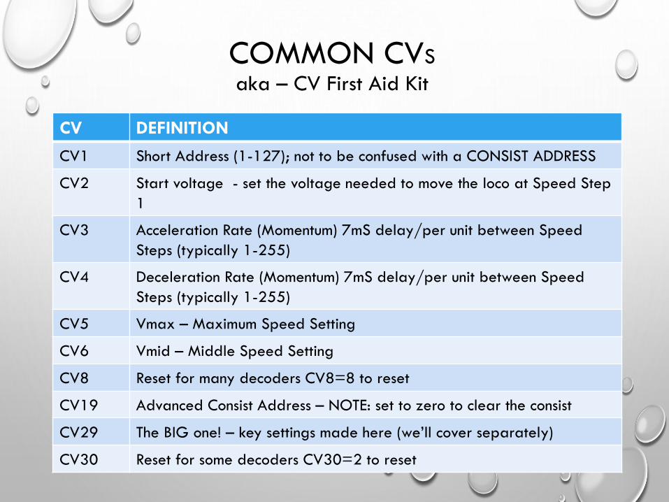
COMMON CVS
aka – CV First Aid Kit
CV DEFINITION
CV1 Short Address (1-127); not to be confused with a CONSIST ADDRESS
CV2 Start voltage - set the voltage needed to move the loco at Speed Step
1
CV3 Acceleration Rate (Momentum) 7mS delay/per unit between Speed
Steps (typically 1-255)
CV4 Deceleration Rate (Momentum) 7mS delay/per unit between Speed
Steps (typically 1-255)
CV5 Vmax – Maximum Speed Setting
CV6 Vmid – Middle Speed Setting
CV8 Reset for many decoders CV8=8 to reset
CV19 Advanced Consist Address – NOTE: set to zero to clear the consist
CV29 The BIG one! – key settings made here (we’ll cover separately)
CV30 Reset for some decoders CV30=2 to reset

The programming window and tabs are brand specific

CV 29
CV 8
CV 7

WHAT CV29 CONTROLS
NO DC / analog – DCC Only
DC / analog and DCC Operation

WHAT CV29 CONTROLS
14 Speed Steps – outdated use only on OLD systems
28 Speed Steps – extended to 128 Speed Steps in newer decoders

WHAT CV29 CONTROLS
Reverse Normal Direction of Travel (RS3 SHORT hood forward)
Normal Direction of Travel (think RS3 long hood forward)

Once you’ve set your address, save this configuration and set
PROGRAMMING to OPS Mode and adjust this setting.

CV 2CV 6CV 5
Standard Speed Control Tab

CV 29 = 50
CV 25 = 10
Slower < 128 Faster > 128
CV 66 CV 95
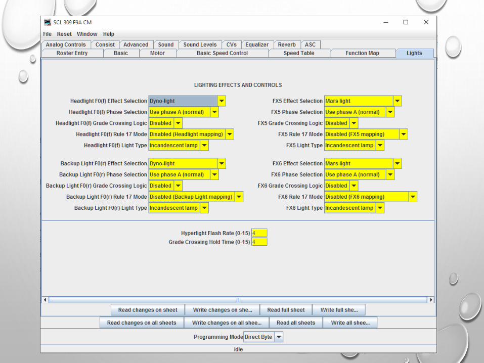
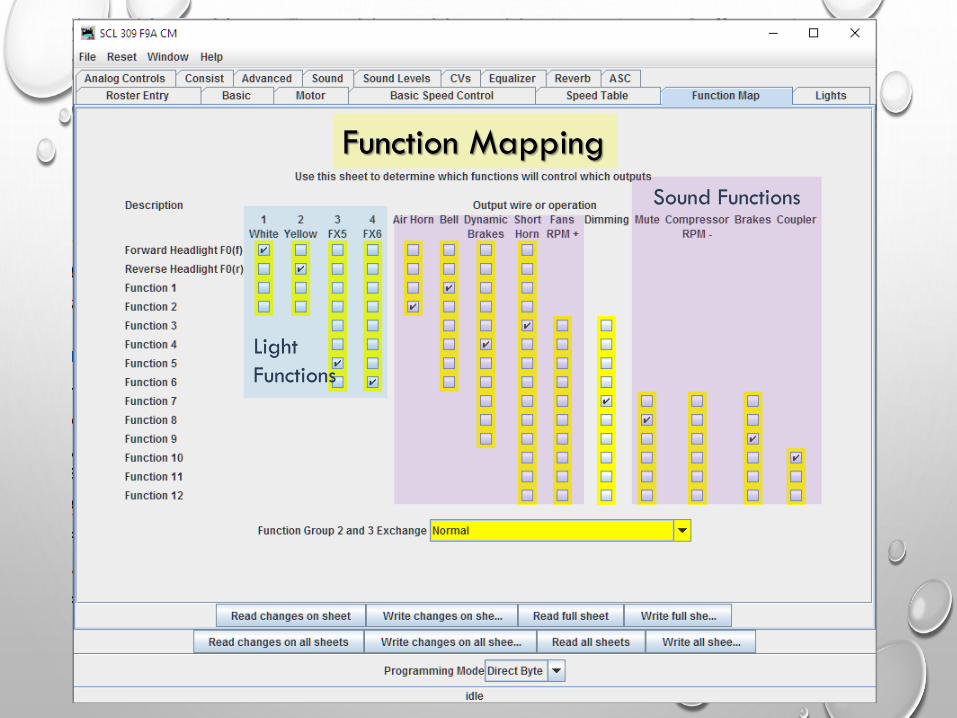
Function Mapping
Light
Functions
Sound Functions


This curve works
great for HO, some
N scale, S and O
gauge

HOW TO IMPORT CV DEFINITIONS AND VALUES FOR ESU DECODERS
• Go to http://www.loksound.com
• Download and install the latest LokProgrammer software (for this project,
you do not need the hardware from ESU)
• Download the software file for your decoder from the ESU website
• Open the file in the LokProgrammer Program and make changes in THIS
program first to make the programming easier.
• Export the CV List to a TEXT file (yourfilename.TXT)
• Open JMRI DecoderPro and select your decoder, and create an new
definition file for your locomotive.
• Import the CV List from LokProgrammer into your JMRI file!


Enter Roster ID Name here


ACKNOWLEDGEMENTS
• JEFF ALEY – PROTOTYPE RAILS
• INTERMOUNTAIN RAILWAY
• JOE FUGATE, MODEL RAILROAD HOBBYIST MAGAZINE
• SUNCOAST MODEL RAILROAD CLUB
ALL OF YOU!

BONUS ROUND


Note the
PORT used

MANUAL SERVER SETTINGS
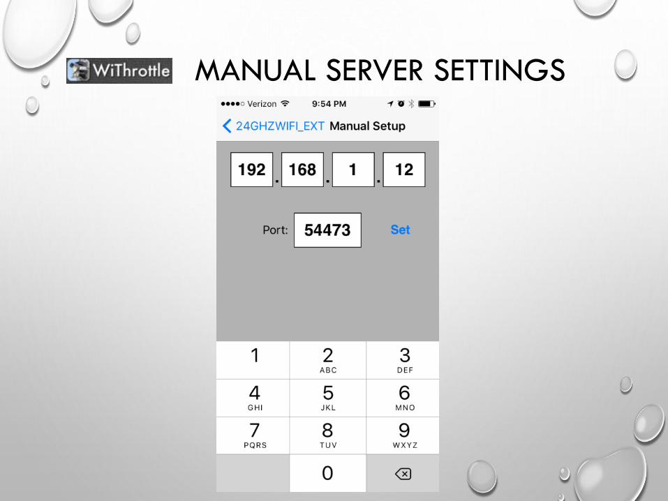
MANUAL SERVER SETTINGS

JMRI RESOURCES
• JMRI WEBSITE: http://jmri.sourceforge.net
• YAHOO GROUP: https://groups.yahoo.com/neo/groups/jmriusers
• DIGITRAX: http://www.digitrax.com
• RR-CIRKITS: http://www.rr-cirkits.com
• NCE: http://www.ncedcc.com

QUESTIONS ?