Plasticity and Deformation Processmetalurji.mu.edu.tr/Icerik/metalurji.mu.edu.tr/Sayfa/Plasticity...
25
Plasticity and Deformation Process Extrusion
Transcript of Plasticity and Deformation Processmetalurji.mu.edu.tr/Icerik/metalurji.mu.edu.tr/Sayfa/Plasticity...

Plasticity and Deformation Process
Extrusion
In extrusion process metal is compressed and forced to flow through a suitably shaped die to form a product with reduced but constant cross section
Hot extrusion is commonly used for many metals to reduce the forces required, eliminate cold working effects and reduce anisotropy
Cold extrusion is common for ductile metals and for simpler shapes
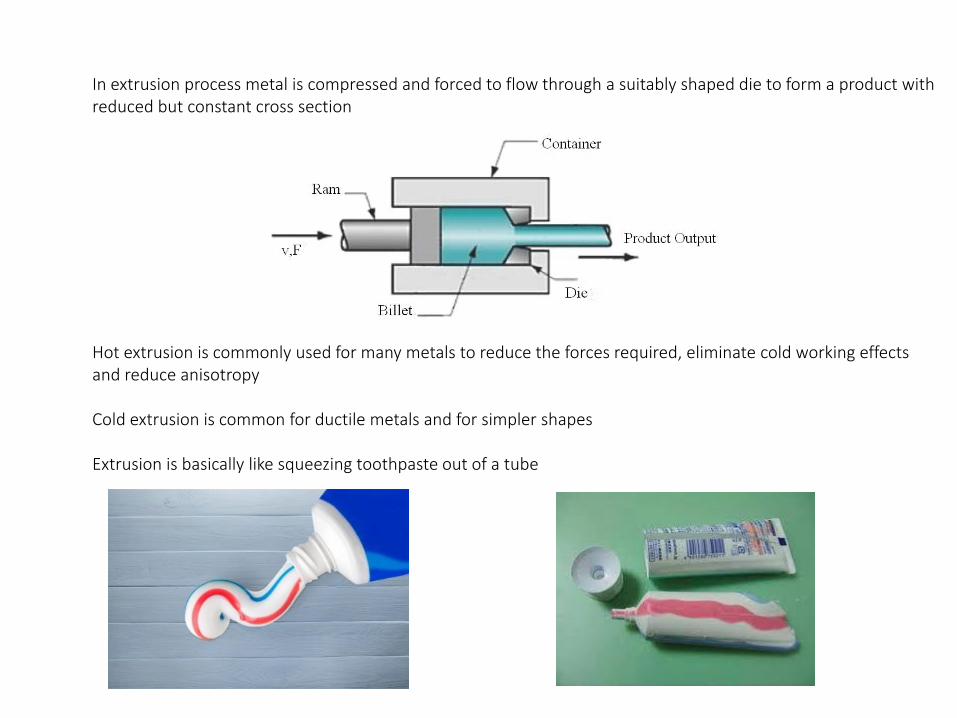
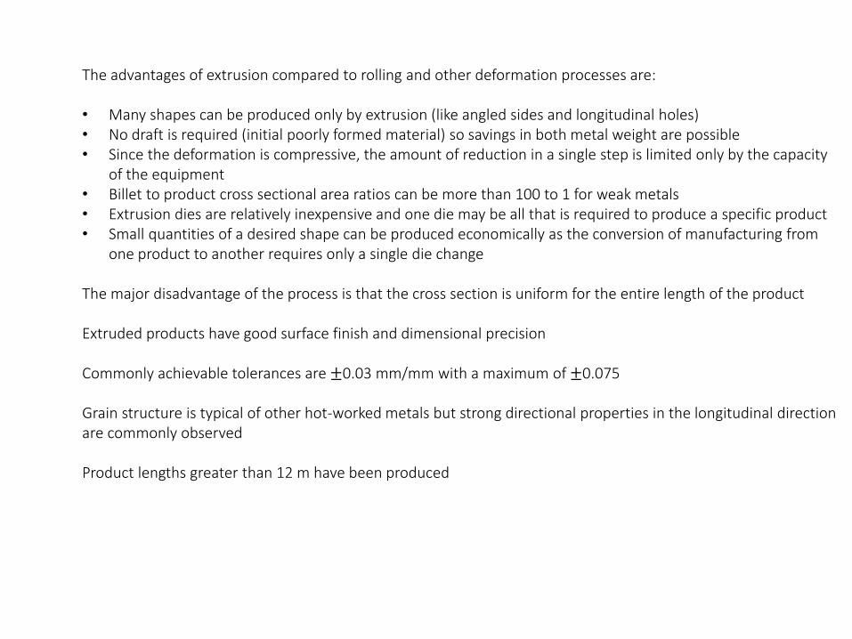
Extrusion is basically like squeezing toothpaste out of a tube

A common extrusion arrangement for metals is to have a heated billet placed inside a tubular chamber
A ram advances from one end, causing the billet to first upset and conform to the chamber
The pressure builds as the ram continues to advance
Metal both deforms and moves towards the die due to pressure and flows plastically through the die

The stress state within the material is triaxial compression
Metal billet is squeezed first in the longitudinal direction then in the radial directions
The radial compression causes friction as the billet moves in the chamber and heats
A stationary zone around the die-exit provides a cushion material which distributes the compressive stresses at an angle around 45 degrees from the chamber wall towards the die exit
Hence some of the longitudinal stress is transformed into shear stress that causes the majority of the plastic deformation
𝜎 =𝐹
𝐴0cos2 𝜃
𝜏 =𝐹
𝐴0sin 𝜃 cos 𝜃

The deformation zone around the die exit has a symmetric rhomboid shape around the longitudinal axis
Stress analysis is done on a cube that deforms to an oblique element due to shear stresses
Plastic deformation results from shear stresses on the sloped sides which make an angle close to 45 degrees with longitudinal and transverse directions and originate from compressive stresses in these directions
Shear stresses exist in the xy and xz directions as elongation occurs only in the x direction

Aluminum, magnesium, copper, lead and alloys of these metals are commonly extruded, taking advantage of the relatively low yield strengths and low hot working temperatures
Steels, stainless steels, nickel based alloys and titanium are far more difficult to extrude because of their high yield strengths and because they have the tendency to weld (join) to the walls of the die and chamber under high temperatures and pressures
However molten glass lubricants enable hot extrusions from these metals as they are able to withstand the high temperatures and adhere to the billet, flowing and thinning in a way that prevents metal-metal contact
Almost any cross-sectional shape can be extruded from the non-ferrous metals
Extrusion presses can extrude any shape that can be enclosed within a 75 cm diameter circle
The shapes and sizes are a bit more limited for steels other high-strength metals
The advantages of extrusion compared to rolling and other deformation processes are:
• Many shapes can be produced only by extrusion (like angled sides and longitudinal holes)• No draft is required (initial poorly formed material) so savings in both metal weight are possible• Since the deformation is compressive, the amount of reduction in a single step is limited only by the capacity
of the equipment• Billet to product cross sectional area ratios can be more than 100 to 1 for weak metals• Extrusion dies are relatively inexpensive and one die may be all that is required to produce a specific product• Small quantities of a desired shape can be produced economically as the conversion of manufacturing from
one product to another requires only a single die change
The major disadvantage of the process is that the cross section is uniform for the entire length of the product
Extruded products have good surface finish and dimensional precision
Commonly achievable tolerances are ±0.03 mm/mm with a maximum of ±0.075
Grain structure is typical of other hot-worked metals but strong directional properties in the longitudinal direction are commonly observed
Product lengths greater than 12 m have been produced

Hot extrusion is done by either the direct or indirect methods
In direct extrusion a solid ram drives the entire billet to and through a stationary die
The ram must provide an additional power to overcome the frictional resistance between the surface of the moving billet and the wall of the chamber in addition to the force required to push the billet through a narrow exit
In indirect extrusion a hollow ram pushes the die back through a stationary, confined billet
The friction between the billet and the chamber wall is eliminated since there is no relative motion
The required force is lower and longer billets can be used due to increased efficiency

The areas below the lines in the figure have units of Newton-meters and are proportional to the work or power required to produce the part
Indirect extrusion is more efficient but also more expensive equipment is required because of the complexity of the process
Removal of the billet material at the stationary end also requires extra maintainence
Extruded products can emerge from both process equipment at rates up to 300 m/min
This high rate increases the temperature of the billet which may be beneficial in some cases where cooling occurs rapidly
Temperature and the deformation rate should be controlled by a sensor feedback mechanism for extrusion of strong metals that produce massive deformation with excessive heat
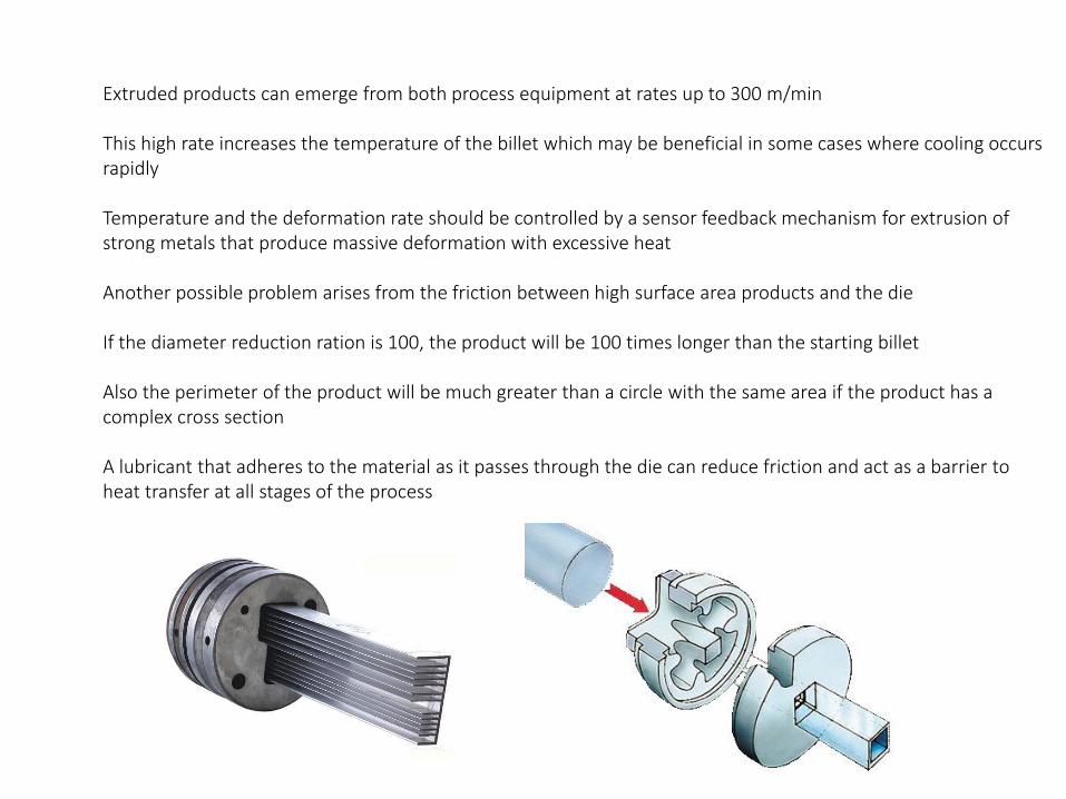
Another possible problem arises from the friction between high surface area products and the die
If the diameter reduction ration is 100, the product will be 100 times longer than the starting billet
Also the perimeter of the product will be much greater than a circle with the same area if the product has a complex cross section
A lubricant that adheres to the material as it passes through the die can reduce friction and act as a barrier to heat transfer at all stages of the process
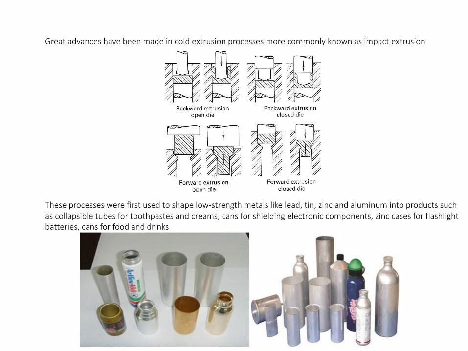
Great advances have been made in cold extrusion processes more commonly known as impact extrusion
These processes were first used to shape low-strength metals like lead, tin, zinc and aluminum into products such as collapsible tubes for toothpastes and creams, cans for shielding electronic components, zinc cases for flashlight batteries, cans for food and drinks
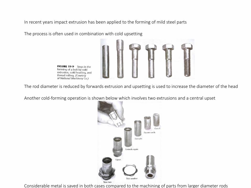
In recent years impact extrusion has been applied to the forming of mild steel parts
The process is often used in combination with cold upsetting
The rod diameter is reduced by forwards extrusion and upsetting is used to increase the diameter of the head
Another cold-forming operation is shown below which involves two extrusions and a central upset
Considerable metal is saved in both cases compared to the machining of parts from larger diameter rods
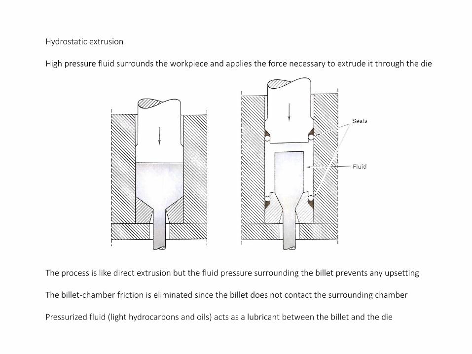
Hydrostatic extrusion
High pressure fluid surrounds the workpiece and applies the force necessary to extrude it through the die
The process is like direct extrusion but the fluid pressure surrounding the billet prevents any upsetting
The billet-chamber friction is eliminated since the billet does not contact the surrounding chamber
Pressurized fluid (light hydrocarbons and oils) acts as a lubricant between the billet and the die
While the process efficiency in hydrostatic extrusion is significantly greater than most other extrusion processes, there are problems related to the associated high fluid pressures which can be as high as 1700 MPa
Fluid leakage and ejection out of the die exit are common problems
Temperatures are limited since the fluid acts also as a heat sink and burns at relatively low temperatures
Hydrostatic extrusion is used when its unique advantages cannot be applied by other methods
One of these cases is pressure to pressure extrusion, a variant of hydrostatic extrusion
The product extrudates from one pressurized chamber to another high pressure chamber and the metal deformation is done in a highly compressed environment
Voids and cracks are suppressed in a compressed environment, resulting in pressure induced ductility
Materials that are relatively brittle at room temperature and atmospheric pressure such as molybdenum, beryllium, tungsten, and their alloys can be plastically deformed without fracture
Conventional extrusion is a discontinuous process, converting billets of some length into separate products
A continuous metal feed can be converted into continuous product if the pushing force can be applied to the periphery of the material rather than the back
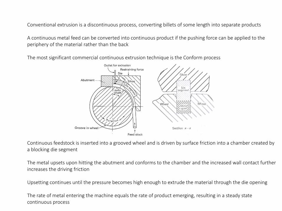
The most significant commercial continuous extrusion technique is the Conform process
Continuous feedstock is inserted into a grooved wheel and is driven by surface friction into a chamber created by a blocking die segment
The metal upsets upon hitting the abutment and conforms to the chamber and the increased wall contact further increases the driving friction
Upsetting continues until the pressure becomes high enough to extrude the material through the die opening
The rate of metal entering the machine equals the rate of product emerging, resulting in a steady state continuous process

Since surface friction is the propulsion force, the feedstock can be solid rod, metal powder, chips from machining, nonmetallic powders, polymeric powders
The process can be used to mix metallic and nonmetallic powders and coextrude them
Even fiber reinforced plastics have been extruded but the most common feed is coiled aluminum or copper rod
Continuous extrusion can be used in place of wire drawing and rolling to produce nonferrous products with small but uniform cross sections
A conform operation can produce an amount of deformation equivalent to ten drawing or cold-rolling passes since extrusion operations perform massive reduction through a single die
In addition, sufficient heat can be generated by the deformation that the product will emerge in an annealed condition that enables further processing without intermediate heat treatment

Hollow shapes like tubes and shapes with more than one longitudinal cavity can be extruded by several methodsThe stationary and moving mandrel processes are common for tubular products
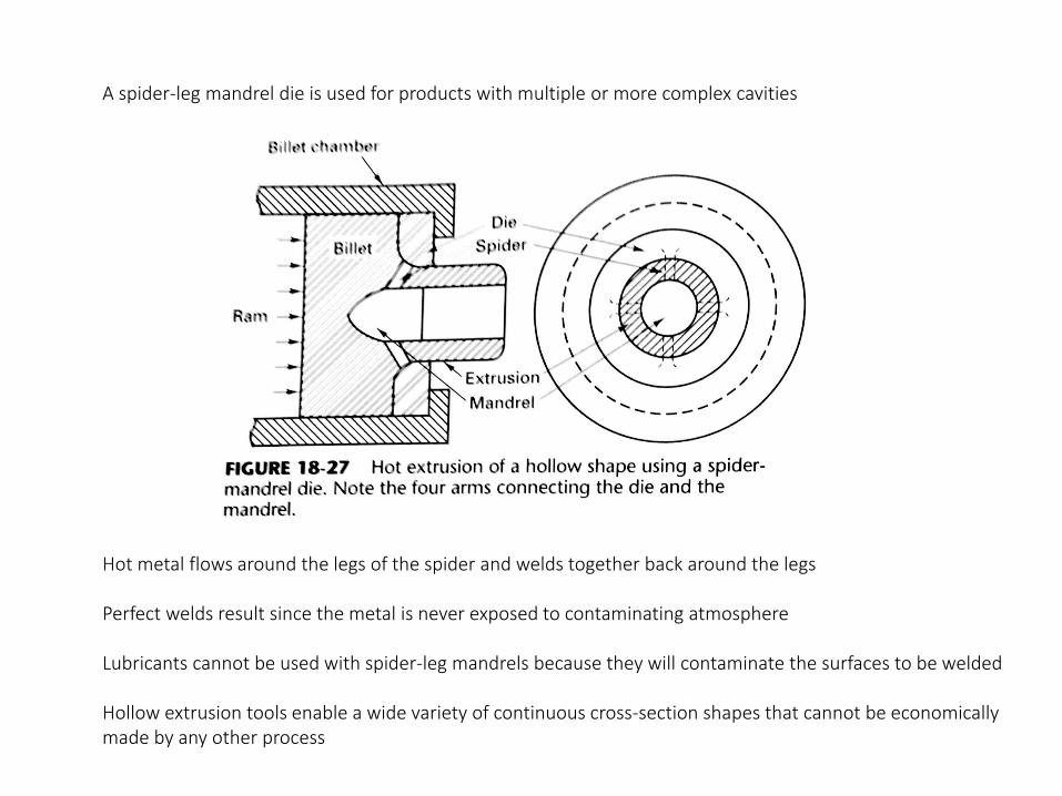
A spider-leg mandrel die is used for products with multiple or more complex cavities
Hot metal flows around the legs of the spider and welds together back around the legs
Perfect welds result since the metal is never exposed to contaminating atmosphere
Lubricants cannot be used with spider-leg mandrels because they will contaminate the surfaces to be welded
Hollow extrusion tools enable a wide variety of continuous cross-section shapes that cannot be economically made by any other process
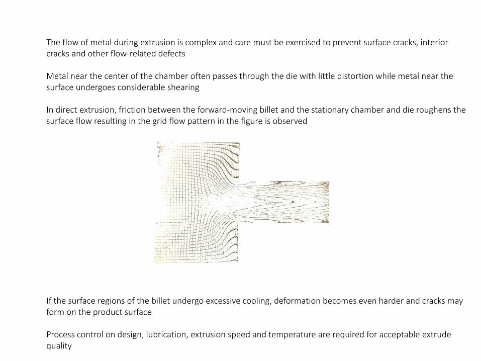
The flow of metal during extrusion is complex and care must be exercised to prevent surface cracks, interior cracks and other flow-related defects
Metal near the center of the chamber often passes through the die with little distortion while metal near the surface undergoes considerable shearing
In direct extrusion, friction between the forward-moving billet and the stationary chamber and die roughens the surface flow resulting in the grid flow pattern in the figure is observed
If the surface regions of the billet undergo excessive cooling, deformation becomes even harder and cracks may form on the product surface
Process control on design, lubrication, extrusion speed and temperature are required for acceptable extrude quality
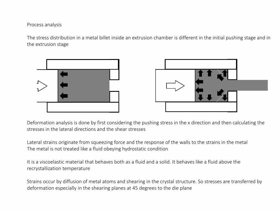
Process analysis
The stress distribution in a metal billet inside an extrusion chamber is different in the initial pushing stage and in the extrusion stage
Deformation analysis is done by first considering the pushing stress in the x direction and then calculating the stresses in the lateral directions and the shear stresses
Lateral strains originate from squeezing force and the response of the walls to the strains in the metal The metal is not treated like a fluid obeying hydrostatic condition
It is a viscoelastic material that behaves both as a fluid and a solid. It behaves like a fluid above the recrystallization temperature
Strains occur by diffusion of metal atoms and shearing in the crystal structure. So stresses are transferred by deformation especially in the shearing planes at 45 degrees to the die plane
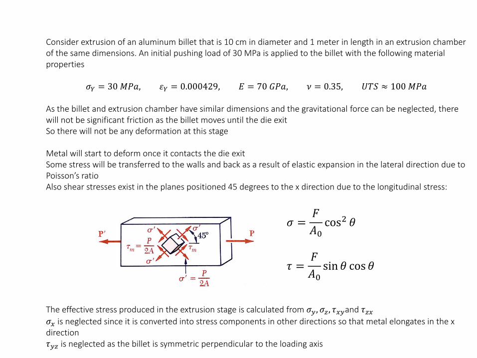
Consider extrusion of an aluminum billet that is 10 cm in diameter and 1 meter in length in an extrusion chamber of the same dimensions. An initial pushing load of 30 MPa is applied to the billet with the following material properties
𝜎𝑌 = 30 𝑀𝑃𝑎, 𝜀𝑌 = 0.000429, 𝐸 = 70 𝐺𝑃𝑎, 𝜈 = 0.35, 𝑈𝑇𝑆 ≈ 100 𝑀𝑃𝑎
As the billet and extrusion chamber have similar dimensions and the gravitational force can be neglected, there will not be significant friction as the billet moves until the die exitSo there will not be any deformation at this stage
Metal will start to deform once it contacts the die exitSome stress will be transferred to the walls and back as a result of elastic expansion in the lateral direction due to Poisson’s ratioAlso shear stresses exist in the planes positioned 45 degrees to the x direction due to the longitudinal stress:
The effective stress produced in the extrusion stage is calculated from 𝜎𝑦 , 𝜎𝑧, 𝜏𝑥𝑦and 𝜏𝑧𝑥𝜎𝑥 is neglected since it is converted into stress components in other directions so that metal elongates in the x direction𝜏𝑦𝑧 is neglected as the billet is symmetric perpendicular to the loading axis
𝜎 =𝐹
𝐴0cos2 𝜃
𝜏 =𝐹
𝐴0sin 𝜃 cos 𝜃

Consider extrusion of an aluminum billet that is 10 cm in diameter and 1 meter in length in an extrusion chamber of the same dimensions. An initial pushing load of -30 MPa is applied to the billet
𝐷𝑒𝑓𝑜𝑟𝑚𝑎𝑡𝑖𝑜𝑛 𝑎𝑡 𝑟𝑜𝑜𝑚 𝑡𝑒𝑚𝑝𝑒𝑟𝑎𝑡𝑢𝑟𝑒
-0.05
0
0.05
0.1
0.15
0.2
-120 -110 -100 -90 -80 -70 -60 -50 -40 -30 -20
Stra
in
Stress (MPa)
Strain x Strain y Shear strain xy
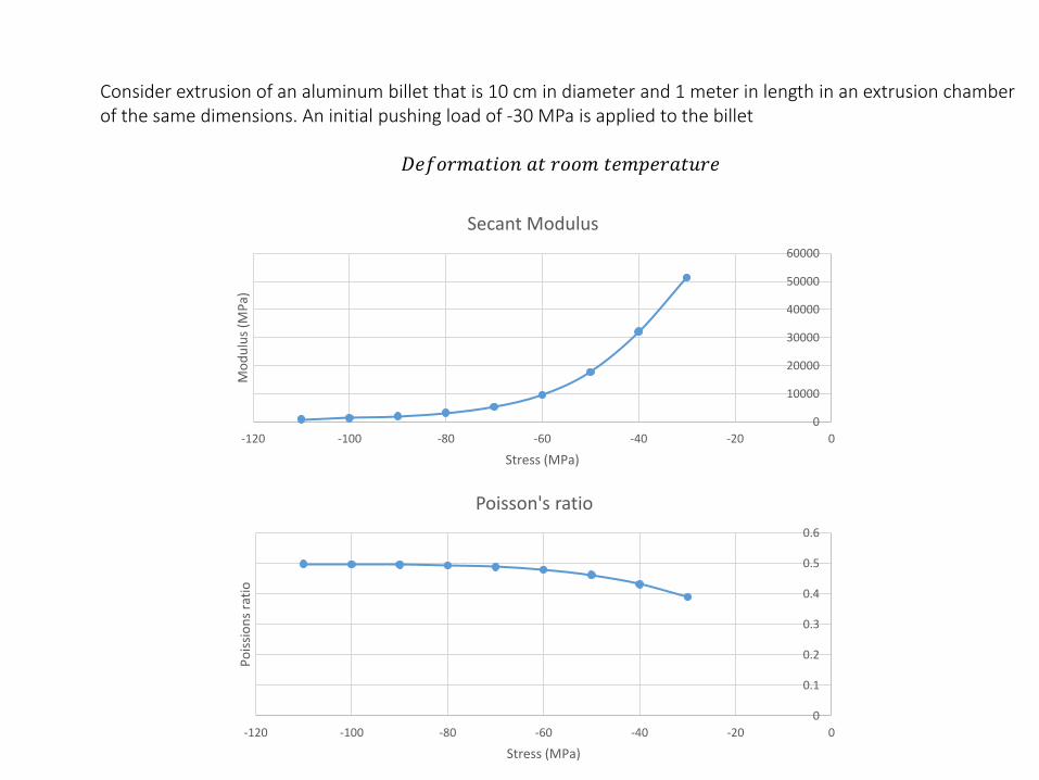
Consider extrusion of an aluminum billet that is 10 cm in diameter and 1 meter in length in an extrusion chamber of the same dimensions. An initial pushing load of -30 MPa is applied to the billet
𝐷𝑒𝑓𝑜𝑟𝑚𝑎𝑡𝑖𝑜𝑛 𝑎𝑡 𝑟𝑜𝑜𝑚 𝑡𝑒𝑚𝑝𝑒𝑟𝑎𝑡𝑢𝑟𝑒
0
10000
20000
30000
40000
50000
60000
-120 -100 -80 -60 -40 -20 0
Mo
du
lus
(MP
a)
Stress (MPa)
Secant Modulus
0
0.1
0.2
0.3
0.4
0.5
0.6
-120 -100 -80 -60 -40 -20 0
Po
issi
on
s ra
tio
Stress (MPa)
Poisson's ratio
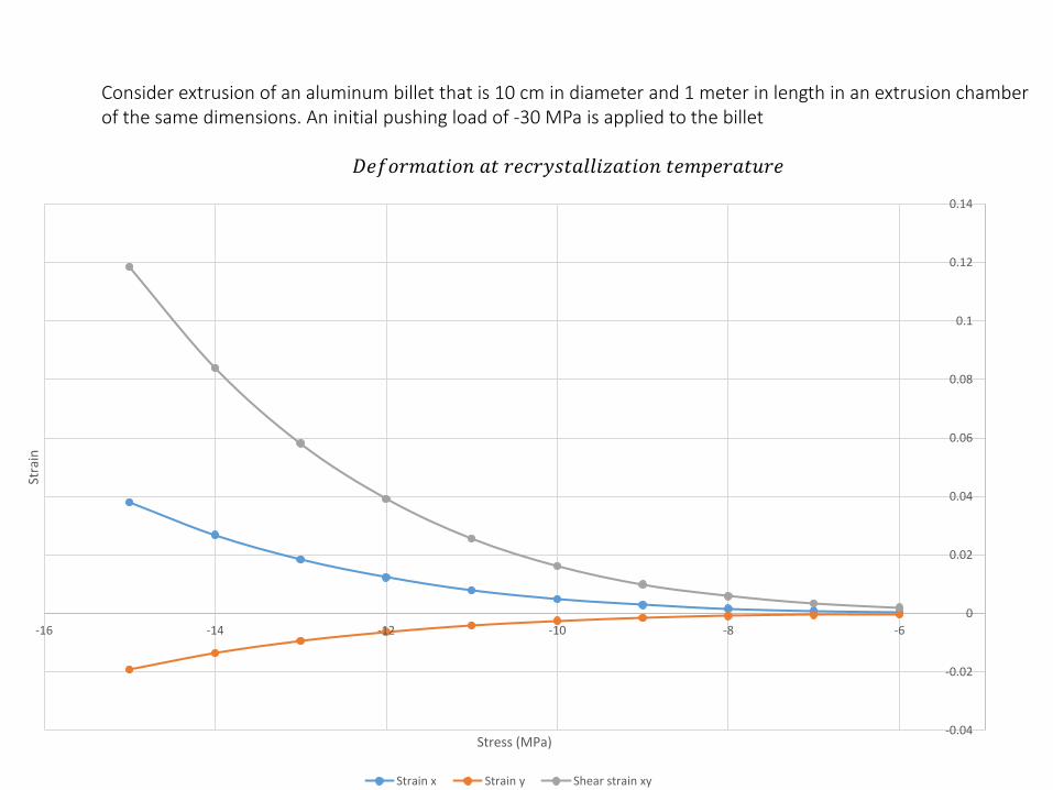
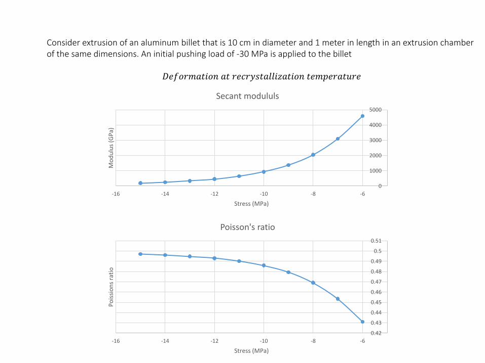
Consider extrusion of an aluminum billet that is 10 cm in diameter and 1 meter in length in an extrusion chamber of the same dimensions. An initial pushing load of -30 MPa is applied to the billet
𝐷𝑒𝑓𝑜𝑟𝑚𝑎𝑡𝑖𝑜𝑛 𝑎𝑡 𝑟𝑒𝑐𝑟𝑦𝑠𝑡𝑎𝑙𝑙𝑖𝑧𝑎𝑡𝑖𝑜𝑛 𝑡𝑒𝑚𝑝𝑒𝑟𝑎𝑡𝑢𝑟𝑒
-0.04
-0.02
0
0.02
0.04
0.06
0.08
0.1
0.12
0.14
-16 -14 -12 -10 -8 -6
Stra
in
Stress (MPa)
Strain x Strain y Shear strain xy
Consider extrusion of an aluminum billet that is 10 cm in diameter and 1 meter in length in an extrusion chamber of the same dimensions. An initial pushing load of -30 MPa is applied to the billet
𝐷𝑒𝑓𝑜𝑟𝑚𝑎𝑡𝑖𝑜𝑛 𝑎𝑡 𝑟𝑒𝑐𝑟𝑦𝑠𝑡𝑎𝑙𝑙𝑖𝑧𝑎𝑡𝑖𝑜𝑛 𝑡𝑒𝑚𝑝𝑒𝑟𝑎𝑡𝑢𝑟𝑒
0.42
0.43
0.44
0.45
0.46
0.47
0.48
0.49
0.5
0.51
-16 -14 -12 -10 -8 -6
Po
issi
on
s ra
tio
Stress (MPa)
Poisson's ratio
0
1000
2000
3000
4000
5000
-16 -14 -12 -10 -8 -6
Mo
du
lus
(GP
a)
Stress (MPa)
Secant modululs