Plasticity and Deformation Processmetalurji.mu.edu.tr/Icerik/metalurji.mu.edu.tr/Sayfa/...The...
34
Plasticity and Deformation Process Yielding
Transcript of Plasticity and Deformation Processmetalurji.mu.edu.tr/Icerik/metalurji.mu.edu.tr/Sayfa/...The...
Plasticity and Deformation Process
Yielding
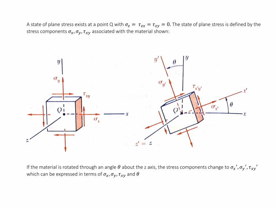
A state of plane stress exists at a point Q with 𝜎𝑧 = 𝜏𝑧𝑥 = 𝜏𝑧𝑦 = 0. The state of plane stress is defined by the
stress components 𝜎𝑥 , 𝜎𝑦 , 𝜏𝑥𝑦 associated with the material shown:
If the material is rotated through an angle 𝜃 about the z axis, the stress components change to 𝜎𝑥′, 𝜎𝑦
′, 𝜏𝑥𝑦′
which can be expressed in terms of 𝜎𝑥 , 𝜎𝑦 , 𝜏𝑥𝑦 and 𝜃
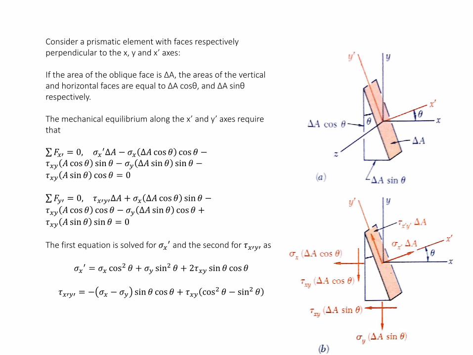
Consider a prismatic element with faces respectively perpendicular to the x, y and x’ axes:
If the area of the oblique face is ΔA, the areas of the vertical and horizontal faces are equal to ΔA cosθ, and ΔA sinθrespectively.
The mechanical equilibrium along the x’ and y’ axes require that
𝐹𝑥′ = 0, 𝜎𝑥′Δ𝐴 − 𝜎𝑥 Δ𝐴 cos 𝜃 cos 𝜃 −
𝜏𝑥𝑦 𝐴 cos 𝜃 sin 𝜃 − 𝜎𝑦 Δ𝐴 sin 𝜃 sin 𝜃 −
𝜏𝑥𝑦 𝐴 sin 𝜃 cos 𝜃 = 0
𝐹𝑦′ = 0, 𝜏𝑥′𝑦′Δ𝐴 + 𝜎𝑥 Δ𝐴 cos 𝜃 sin 𝜃 −
𝜏𝑥𝑦 𝐴 cos 𝜃 cos 𝜃 − 𝜎𝑦 Δ𝐴 sin 𝜃 cos 𝜃 +
𝜏𝑥𝑦 𝐴 sin 𝜃 sin 𝜃 = 0
The first equation is solved for 𝜎𝑥′ and the second for 𝜏𝑥′𝑦′ as
𝜎𝑥′ = 𝜎𝑥 cos
2 𝜃 + 𝜎𝑦 sin2 𝜃 + 2𝜏𝑥𝑦 sin 𝜃 cos 𝜃
𝜏𝑥′𝑦′ = − 𝜎𝑥 − 𝜎𝑦 sin 𝜃 cos 𝜃 + 𝜏𝑥𝑦 cos2 𝜃 − sin2 𝜃
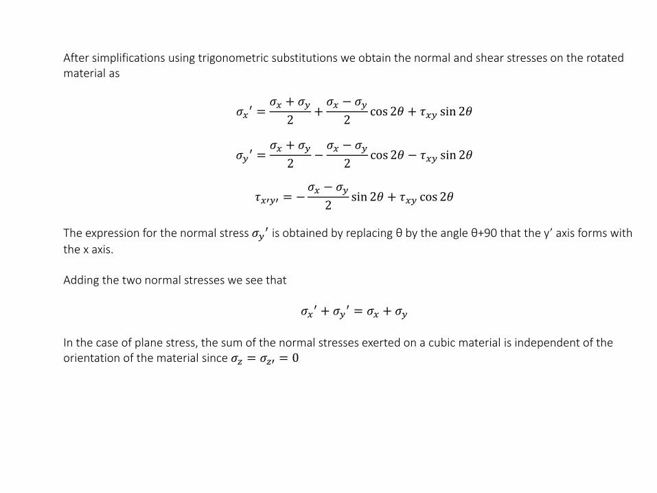
After simplifications using trigonometric substitutions we obtain the normal and shear stresses on the rotated material as
𝜎𝑥′ =
𝜎𝑥 + 𝜎𝑦
2+𝜎𝑥 − 𝜎𝑦
2cos 2𝜃 + 𝜏𝑥𝑦 sin 2𝜃
𝜎𝑦′ =
𝜎𝑥 + 𝜎𝑦
2−𝜎𝑥 − 𝜎𝑦
2cos 2𝜃 − 𝜏𝑥𝑦 sin 2𝜃
𝜏𝑥′𝑦′ = −𝜎𝑥 − 𝜎𝑦
2sin 2𝜃 + 𝜏𝑥𝑦 cos 2𝜃
The expression for the normal stress 𝜎𝑦′ is obtained by replacing θ by the angle θ+90 that the y’ axis forms with
the x axis.
Adding the two normal stresses we see that
𝜎𝑥′ + 𝜎𝑦
′ = 𝜎𝑥 + 𝜎𝑦
In the case of plane stress, the sum of the normal stresses exerted on a cubic material is independent of the orientation of the material since 𝜎𝑧 = 𝜎𝑧′ = 0
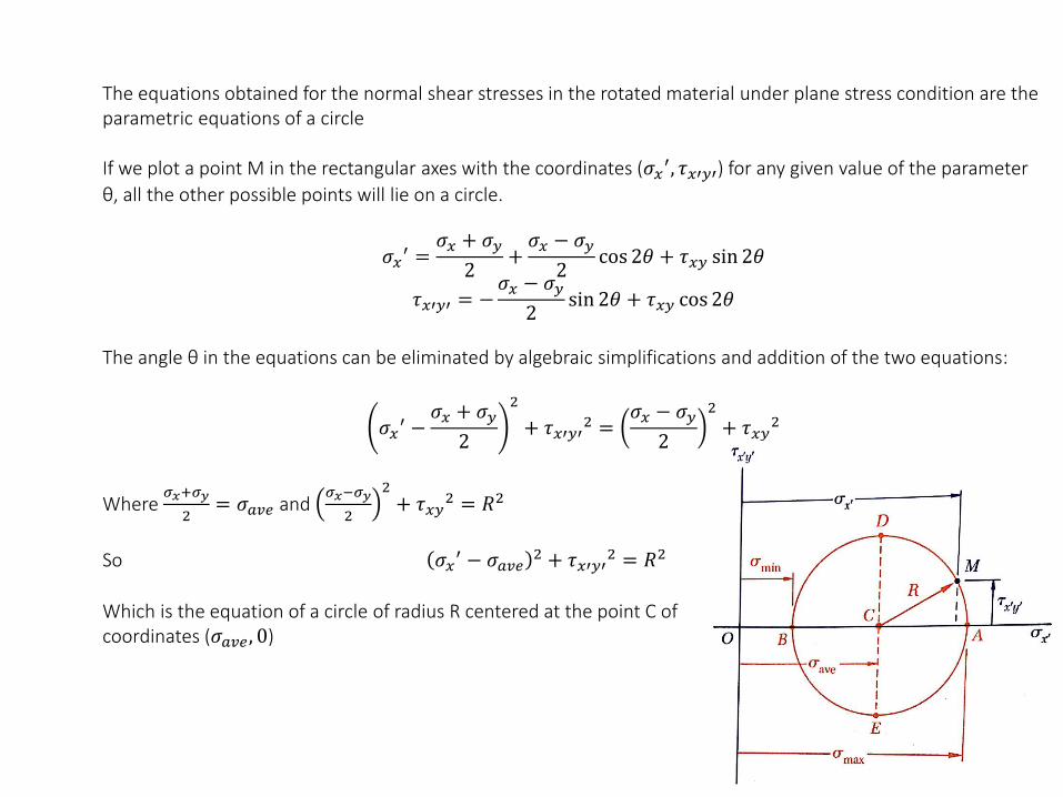
The equations obtained for the normal shear stresses in the rotated material under plane stress condition are the parametric equations of a circle
If we plot a point M in the rectangular axes with the coordinates (𝜎𝑥′, 𝜏𝑥′𝑦′) for any given value of the parameter
θ, all the other possible points will lie on a circle.
𝜎𝑥′ =
𝜎𝑥 + 𝜎𝑦
2+𝜎𝑥 − 𝜎𝑦
2cos 2𝜃 + 𝜏𝑥𝑦 sin 2𝜃
𝜏𝑥′𝑦′ = −𝜎𝑥 − 𝜎𝑦
2sin 2𝜃 + 𝜏𝑥𝑦 cos 2𝜃
The angle θ in the equations can be eliminated by algebraic simplifications and addition of the two equations:
𝜎𝑥′ −
𝜎𝑥 + 𝜎𝑦
2
2
+ 𝜏𝑥′𝑦′2 =
𝜎𝑥 − 𝜎𝑦
2
2
+ 𝜏𝑥𝑦2
Where 𝜎𝑥+𝜎𝑦
2= 𝜎𝑎𝑣𝑒 and
𝜎𝑥−𝜎𝑦
2
2+ 𝜏𝑥𝑦
2 = 𝑅2
So 𝜎𝑥′ − 𝜎𝑎𝑣𝑒
2 + 𝜏𝑥′𝑦′2 = 𝑅2
Which is the equation of a circle of radius R centered at the point C of coordinates (𝜎𝑎𝑣𝑒 , 0)
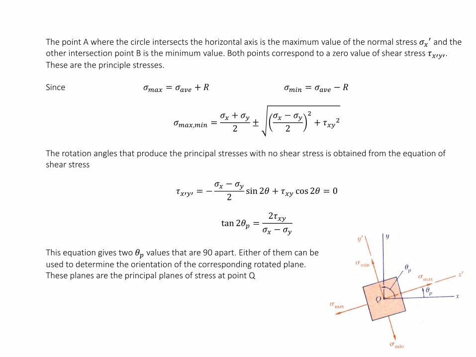
The point A where the circle intersects the horizontal axis is the maximum value of the normal stress 𝜎𝑥′ and the
other intersection point B is the minimum value. Both points correspond to a zero value of shear stress 𝜏𝑥′𝑦′.
These are the principle stresses.
Since 𝜎𝑚𝑎𝑥 = 𝜎𝑎𝑣𝑒 + 𝑅 𝜎𝑚𝑖𝑛 = 𝜎𝑎𝑣𝑒 − 𝑅
𝜎𝑚𝑎𝑥,𝑚𝑖𝑛 =𝜎𝑥 + 𝜎𝑦
2±
𝜎𝑥 − 𝜎𝑦
2
2
+ 𝜏𝑥𝑦2
The rotation angles that produce the principal stresses with no shear stress is obtained from the equation of shear stress
𝜏𝑥′𝑦′ = −𝜎𝑥 − 𝜎𝑦
2sin 2𝜃 + 𝜏𝑥𝑦 cos 2𝜃 = 0
tan 2𝜃𝑝 =2𝜏𝑥𝑦
𝜎𝑥 − 𝜎𝑦
This equation gives two 𝜃𝑝 values that are 90 apart. Either of them can be
used to determine the orientation of the corresponding rotated plane. These planes are the principal planes of stress at point Q
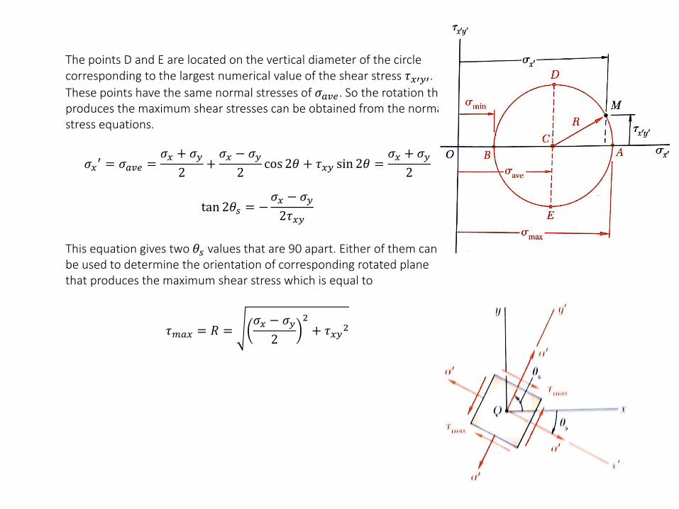
The points D and E are located on the vertical diameter of the circle corresponding to the largest numerical value of the shear stress 𝜏𝑥′𝑦′.
These points have the same normal stresses of 𝜎𝑎𝑣𝑒. So the rotation that produces the maximum shear stresses can be obtained from the normal stress equations.
𝜎𝑥′ = 𝜎𝑎𝑣𝑒 =
𝜎𝑥 + 𝜎𝑦
2+𝜎𝑥 − 𝜎𝑦
2cos 2𝜃 + 𝜏𝑥𝑦 sin 2𝜃 =
𝜎𝑥 + 𝜎𝑦
2
tan 2𝜃𝑠 = −𝜎𝑥 − 𝜎𝑦
2𝜏𝑥𝑦
This equation gives two 𝜃𝑠 values that are 90 apart. Either of them can be used to determine the orientation of corresponding rotated plane that produces the maximum shear stress which is equal to
𝜏𝑚𝑎𝑥 = 𝑅 =𝜎𝑥 − 𝜎𝑦
2
2
+ 𝜏𝑥𝑦2
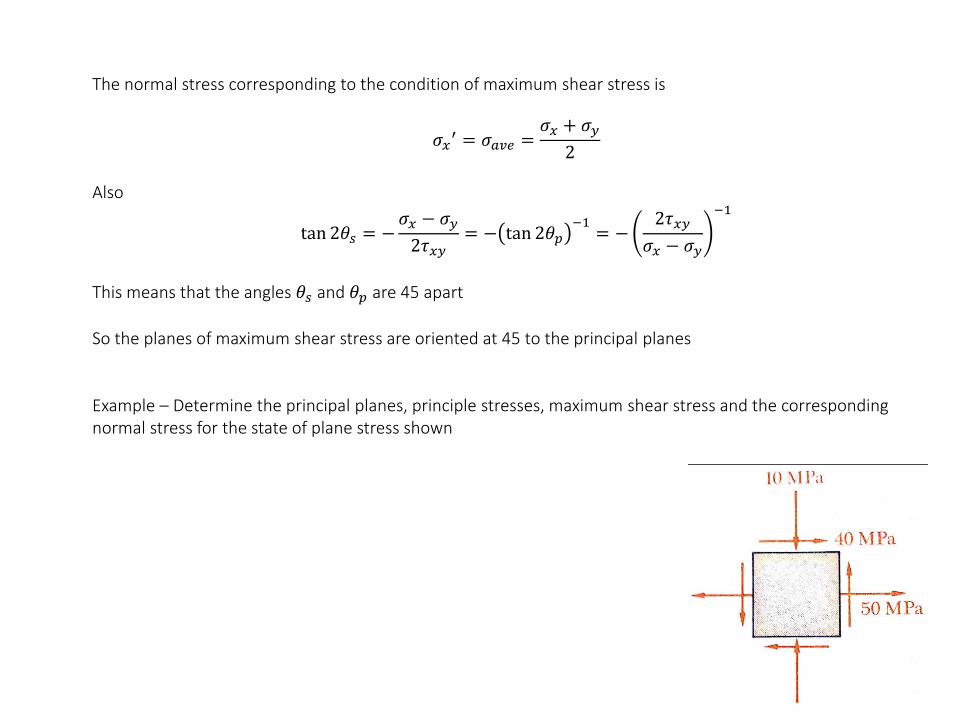
The normal stress corresponding to the condition of maximum shear stress is
𝜎𝑥′ = 𝜎𝑎𝑣𝑒 =
𝜎𝑥 + 𝜎𝑦
2
Also
tan 2𝜃𝑠 = −𝜎𝑥 − 𝜎𝑦
2𝜏𝑥𝑦= − tan 2𝜃𝑝
−1= −
2𝜏𝑥𝑦
𝜎𝑥 − 𝜎𝑦
−1
This means that the angles 𝜃𝑠 and 𝜃𝑝 are 45 apart
So the planes of maximum shear stress are oriented at 45 to the principal planes
Example – Determine the principal planes, principle stresses, maximum shear stress and the corresponding normal stress for the state of plane stress shown
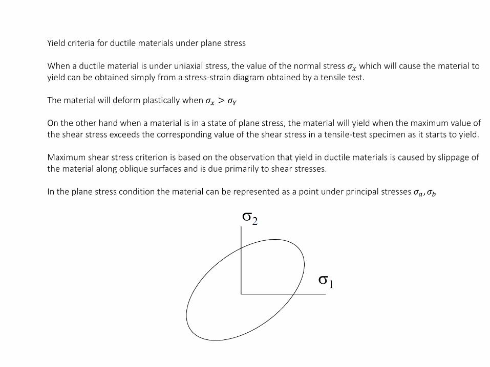
Yield criteria for ductile materials under plane stress
When a ductile material is under uniaxial stress, the value of the normal stress 𝜎𝑥 which will cause the material to yield can be obtained simply from a stress-strain diagram obtained by a tensile test.
The material will deform plastically when 𝜎𝑥 > 𝜎𝑌
On the other hand when a material is in a state of plane stress, the material will yield when the maximum value of the shear stress exceeds the corresponding value of the shear stress in a tensile-test specimen as it starts to yield.
Maximum shear stress criterion is based on the observation that yield in ductile materials is caused by slippage of the material along oblique surfaces and is due primarily to shear stresses.
In the plane stress condition the material can be represented as a point under principal stresses 𝜎𝑎 , 𝜎𝑏
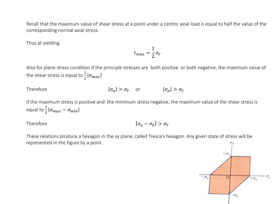
Recall that the maximum value of shear stress at a point under a centric axial load is equal to half the value of the corresponding normal axial stress.
Thus at yielding
𝜏𝑚𝑎𝑥 =1
2𝜎𝑌
Also for plane stress condition if the principle stresses are both positive or both negative, the maximum value of
the shear stress is equal to 1
2𝜎𝑚𝑎𝑥
Therefore 𝜎𝑎 > 𝜎𝑌 or 𝜎𝑎 > 𝜎𝑌
If the maximum stress is positive and the minimum stress negative, the maximum value of the shear stress is
equal to 1
2𝜎𝑚𝑎𝑥 − 𝜎𝑚𝑖𝑛
Therefore 𝜎𝑎 − 𝜎𝑏 > 𝜎𝑌
These relations produce a hexagon in the xy plane, called Tresca’s hexagon. Any given state of stress will be represented in the figure by a point.
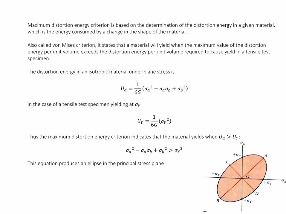
Maximum distortion energy criterion is based on the determination of the distortion energy in a given material, which is the energy consumed by a change in the shape of the material.
Also called von Mises criterion, it states that a material will yield when the maximum value of the distortion energy per unit volume exceeds the distortion energy per unit volume required to cause yield in a tensile test specimen.
The distortion energy in an isotropic material under plane stress is
𝑈𝑑 =1
6𝐺𝜎𝑎
2 − 𝜎𝑎𝜎𝑏 + 𝜎𝑏2
In the case of a tensile test specimen yielding at 𝜎𝑌
𝑈𝑌 =1
6𝐺𝜎𝑌2
Thus the maximum distortion energy criterion indicates that the material yields when 𝑈𝑑 > 𝑈𝑌:
𝜎𝑎2 − 𝜎𝑎𝜎𝑏 + 𝜎𝑏
2 > 𝜎𝑌2
This equation produces an ellipse in the principal stress plane
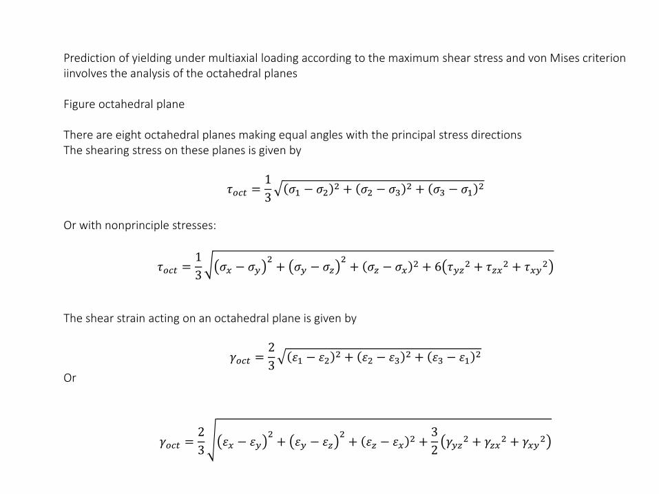
Prediction of yielding under multiaxial loading according to the maximum shear stress and von Mises criterion iinvolves the analysis of the octahedral planes
Figure octahedral plane
There are eight octahedral planes making equal angles with the principal stress directionsThe shearing stress on these planes is given by
𝜏𝑜𝑐𝑡 =1
3𝜎1 − 𝜎2
2 + 𝜎2 − 𝜎32 + 𝜎3 − 𝜎1
2
Or with nonprinciple stresses:
𝜏𝑜𝑐𝑡 =1
3𝜎𝑥 − 𝜎𝑦
2+ 𝜎𝑦 − 𝜎𝑧
2+ 𝜎𝑧 − 𝜎𝑥
2 + 6 𝜏𝑦𝑧2 + 𝜏𝑧𝑥
2 + 𝜏𝑥𝑦2
The shear strain acting on an octahedral plane is given by
𝛾𝑜𝑐𝑡 =2
3𝜀1 − 𝜀2
2 + 𝜀2 − 𝜀32 + 𝜀3 − 𝜀1
2
Or
𝛾𝑜𝑐𝑡 =2
3𝜀𝑥 − 𝜀𝑦
2+ 𝜀𝑦 − 𝜀𝑧
2+ 𝜀𝑧 − 𝜀𝑥
2 +3
2𝛾𝑦𝑧
2 + 𝛾𝑧𝑥2 + 𝛾𝑥𝑦
2
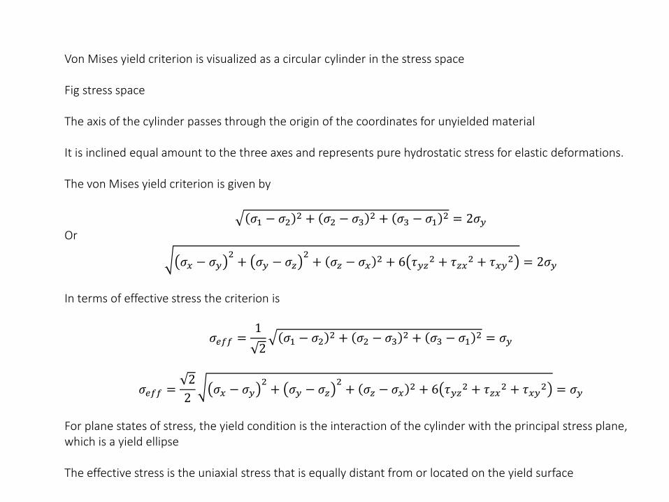
Von Mises yield criterion is visualized as a circular cylinder in the stress space
Fig stress space
The axis of the cylinder passes through the origin of the coordinates for unyielded material
It is inclined equal amount to the three axes and represents pure hydrostatic stress for elastic deformations.
The von Mises yield criterion is given by
𝜎1 − 𝜎22 + 𝜎2 − 𝜎3
2 + 𝜎3 − 𝜎12 = 2𝜎𝑦
Or
𝜎𝑥 − 𝜎𝑦2+ 𝜎𝑦 − 𝜎𝑧
2+ 𝜎𝑧 − 𝜎𝑥
2 + 6 𝜏𝑦𝑧2 + 𝜏𝑧𝑥
2 + 𝜏𝑥𝑦2 = 2𝜎𝑦
In terms of effective stress the criterion is
𝜎𝑒𝑓𝑓 =1
2𝜎1 − 𝜎2
2 + 𝜎2 − 𝜎32 + 𝜎3 − 𝜎1
2 = 𝜎𝑦
𝜎𝑒𝑓𝑓 =2
2𝜎𝑥 − 𝜎𝑦
2+ 𝜎𝑦 − 𝜎𝑧
2+ 𝜎𝑧 − 𝜎𝑥
2 + 6 𝜏𝑦𝑧2 + 𝜏𝑧𝑥
2 + 𝜏𝑥𝑦2 = 𝜎𝑦
For plane states of stress, the yield condition is the interaction of the cylinder with the principal stress plane, which is a yield ellipse
The effective stress is the uniaxial stress that is equally distant from or located on the yield surface
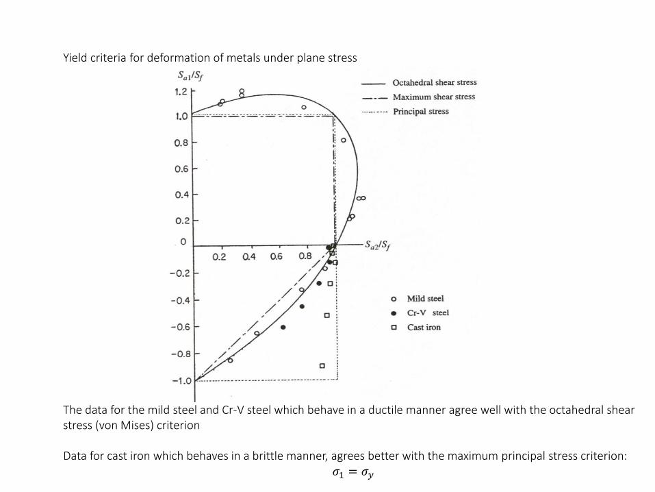
Yield criteria for deformation of metals under plane stress
The data for the mild steel and Cr-V steel which behave in a ductile manner agree well with the octahedral shear stress (von Mises) criterion
Data for cast iron which behaves in a brittle manner, agrees better with the maximum principal stress criterion:𝜎1 = 𝜎𝑦
Brittle materials fail suddenly in a tensile test by rupture without any prior yielding.
When a brittle material is under uniaxial tensile stress, the value of the normal stress which causes it to fail is equal to the ultimate strength of the material as determined from a tensile test.
When a brittle material is under plane stress, the principal stresses are compared to the ultimate strength obtained from the uniaxial tensile test.
Maximum normal stress criterion states that a brittle material will fail when the maximum normal stress exceeds the ultimate strength obtained from the uniaxial tensile test:
𝜎𝑎 > 𝜎𝑈 or 𝜎𝑎 > 𝜎𝑈
This criterion forms a square area centered on the xy plane. The criterion is based on the assumption that the ultimate strength of materials under tension and compression are equal, which is an overestimation for most materials as the presence of cracks and flaws often weaken the material under tension
Elasticity exercises
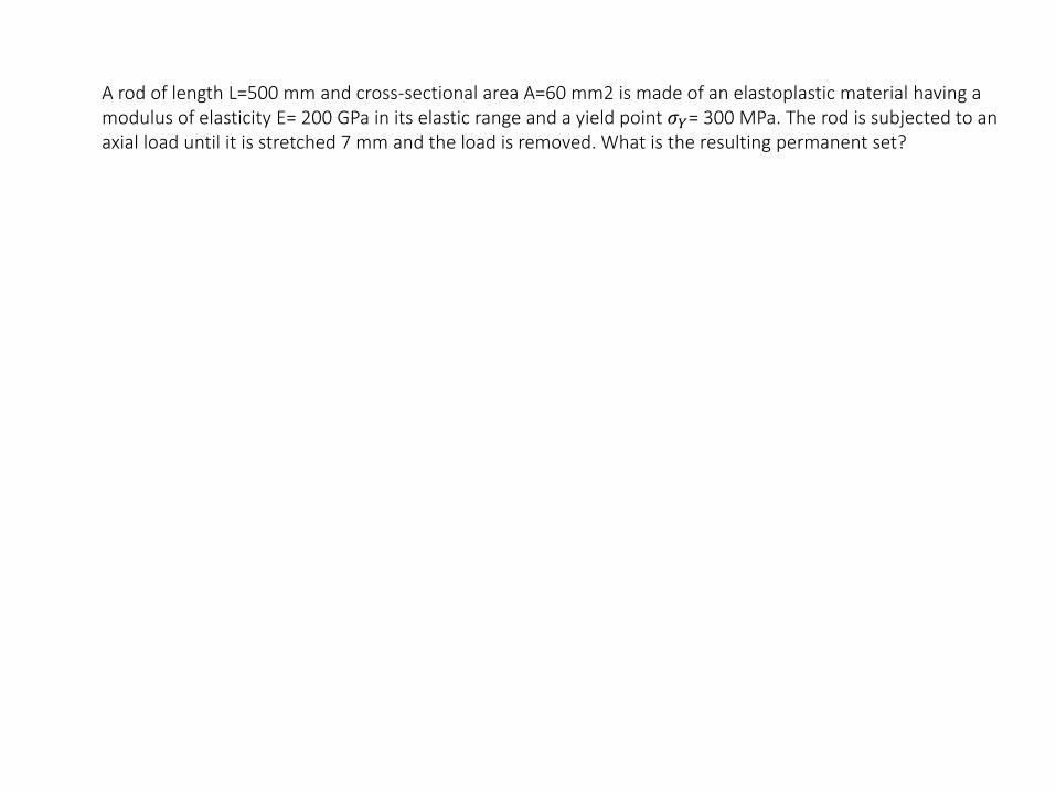
A rod of length L=500 mm and cross-sectional area A=60 mm2 is made of an elastoplastic material having a modulus of elasticity E= 200 GPa in its elastic range and a yield point 𝜎𝑌= 300 MPa. The rod is subjected to an axial load until it is stretched 7 mm and the load is removed. What is the resulting permanent set?
A nylon thread is to be subjected to an 11-N tension. What is the required diameter of the thread if its modulus is 3.1 GPa, the maximum allowable normal stress is 40 MPa and the length of the thread should not increase by more than 1%.
An aluminum test specimen that is in the shape of a bar of length 300mm*60mm*15mm is subjected to two equal and opposite centric axial forces of magnitude P. What is the maximum allowable value of P and the corresponding total elongation of the specimen if E= 70 GPa and 𝜎𝑎𝑙𝑙𝑜𝑤𝑎𝑏𝑙𝑒= 200 MPa.
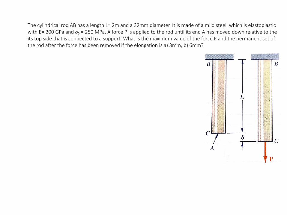
The cylindrical rod AB has a length L= 2m and a 32mm diameter. It is made of a mild steel which is elastoplastic with E= 200 GPa and 𝜎𝑌= 250 MPa. A force P is applied to the rod until its end A has moved down relative to the its top side that is connected to a support. What is the maximum value of the force P and the permanent set of the rod after the force has been removed if the elongation is a) 3mm, b) 6mm?
A steel rod of length L and uniform cross section of area A is attached to rigid supports and is unstressed at a temperature of 20 C. The steel is assumed to be elastoplastic with E= 200 GPa and 𝜎𝑌= 250 MPa. What is the stress in the rod after the temperature has been raised to 150 C if the coefficient of thermal expansion is 11.7*10-
6/C?
A cylindrical block of brass, that is 160 mm high and 120 mm in diameter is lowered into the ocean to a depth of 7500 m where the pressure is 75 MPa. Determine a) the change in height of the block, b) the change in its diameter, c) the change in its volume if the E= 105 GPa and 𝜐= 0.35. What is the pressure which should be applied d) to its top and bottom faces only, and e) to its cylindrical surface only to cause the same change of volume as the hydrostatic pressure?
What is the change in volume of a steel block of dimensions 80*60*40 mm when it is subjected to the hydrostatic pressure p= 180 MPa? What are the changes in the length of each side? E= 200 GPa, 𝜐= 0.29.
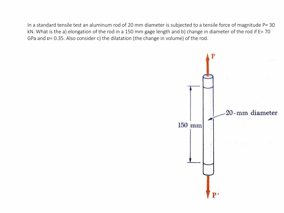
In a standard tensile test an aluminum rod of 20 mm diameter is subjected to a tensile force of magnitude P= 30 kN. What is the a) elongation of the rod in a 150 mm gage length and b) change in diameter of the rod if E= 70 GPa and 𝜐= 0.35. Also consider c) the dilatation (the change in volume) of the rod.

In a standard tensile test a 20 mm diameter rod made of an experimental polymer is subjected to a tensile force of magnitude P= 6 kN. What are the modulus of elasticity, the modulus of rigidity and the poisson’s ratio of the material if the elongation is 14 mm and decrease in diameter is 0.85 mm?
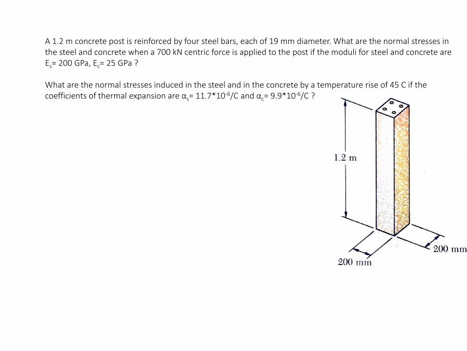
A 1.2 m concrete post is reinforced by four steel bars, each of 19 mm diameter. What are the normal stresses in the steel and concrete when a 700 kN centric force is applied to the post if the moduli for steel and concrete are Es= 200 GPa, Ec= 25 GPa ?
What are the normal stresses induced in the steel and in the concrete by a temperature rise of 45 C if the coefficients of thermal expansion are αs= 11.7*10-6/C and αc= 9.9*10-6/C ?
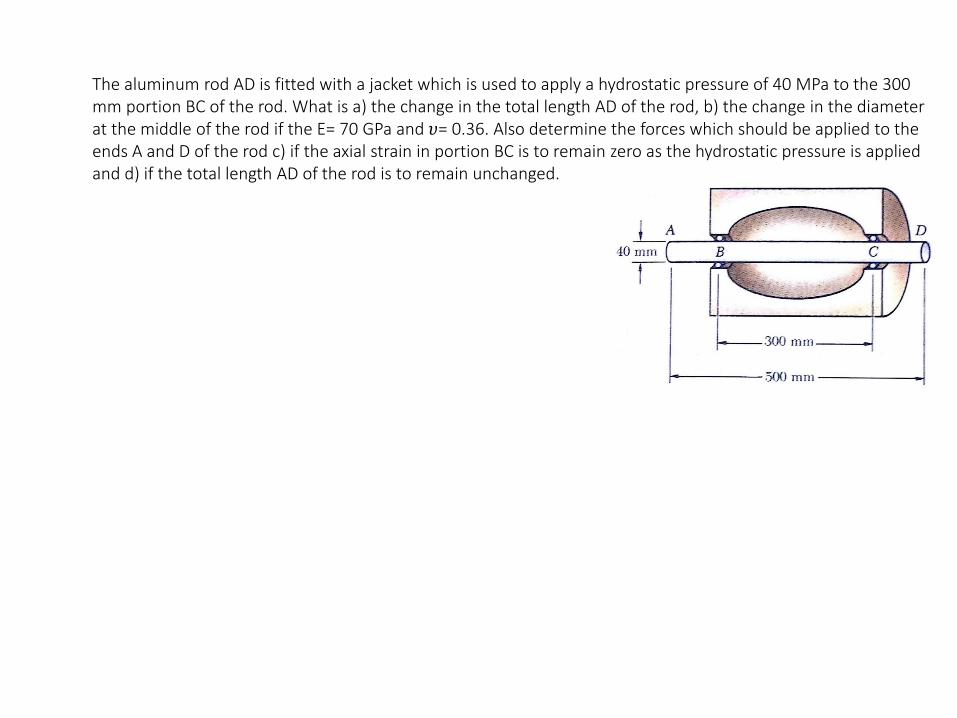
The aluminum rod AD is fitted with a jacket which is used to apply a hydrostatic pressure of 40 MPa to the 300 mm portion BC of the rod. What is a) the change in the total length AD of the rod, b) the change in the diameter at the middle of the rod if the E= 70 GPa and 𝜐= 0.36. Also determine the forces which should be applied to the ends A and D of the rod c) if the axial strain in portion BC is to remain zero as the hydrostatic pressure is applied and d) if the total length AD of the rod is to remain unchanged.
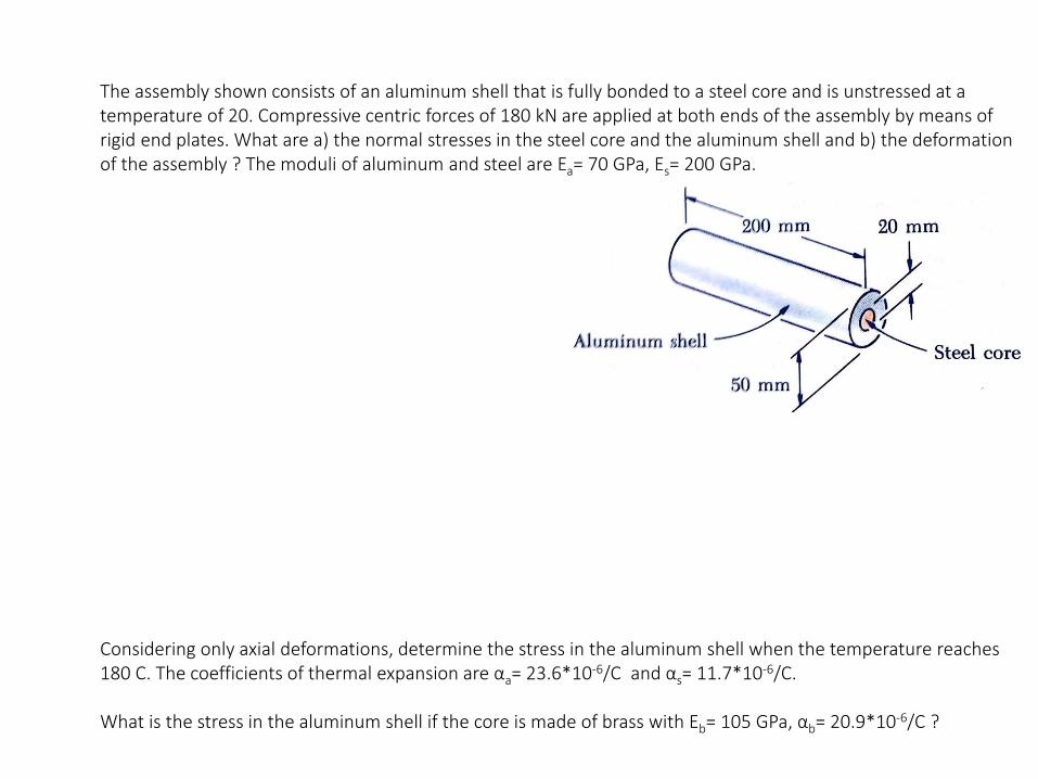
The assembly shown consists of an aluminum shell that is fully bonded to a steel core and is unstressed at a temperature of 20. Compressive centric forces of 180 kN are applied at both ends of the assembly by means of rigid end plates. What are a) the normal stresses in the steel core and the aluminum shell and b) the deformation of the assembly ? The moduli of aluminum and steel are Ea= 70 GPa, Es= 200 GPa.
Considering only axial deformations, determine the stress in the aluminum shell when the temperature reaches 180 C. The coefficients of thermal expansion are αa= 23.6*10-6/C and αs= 11.7*10-6/C.
What is the stress in the aluminum shell if the core is made of brass with Eb= 105 GPa, αb= 20.9*10-6/C ?
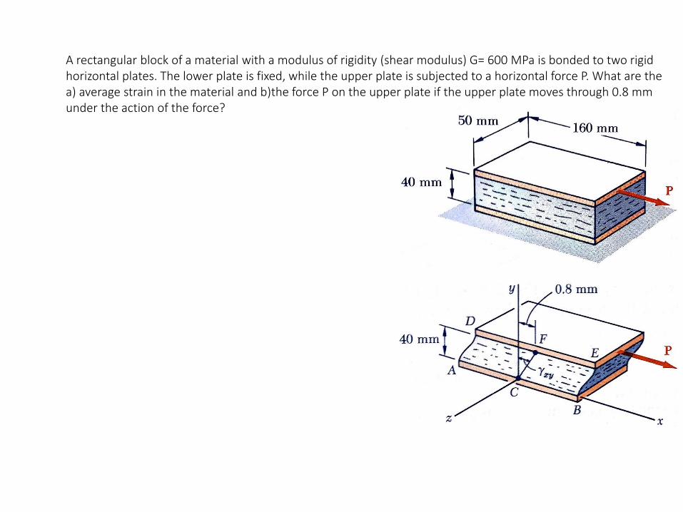
A rectangular block of a material with a modulus of rigidity (shear modulus) G= 600 MPa is bonded to two rigid horizontal plates. The lower plate is fixed, while the upper plate is subjected to a horizontal force P. What are the a) average strain in the material and b)the force P on the upper plate if the upper plate moves through 0.8 mm under the action of the force?
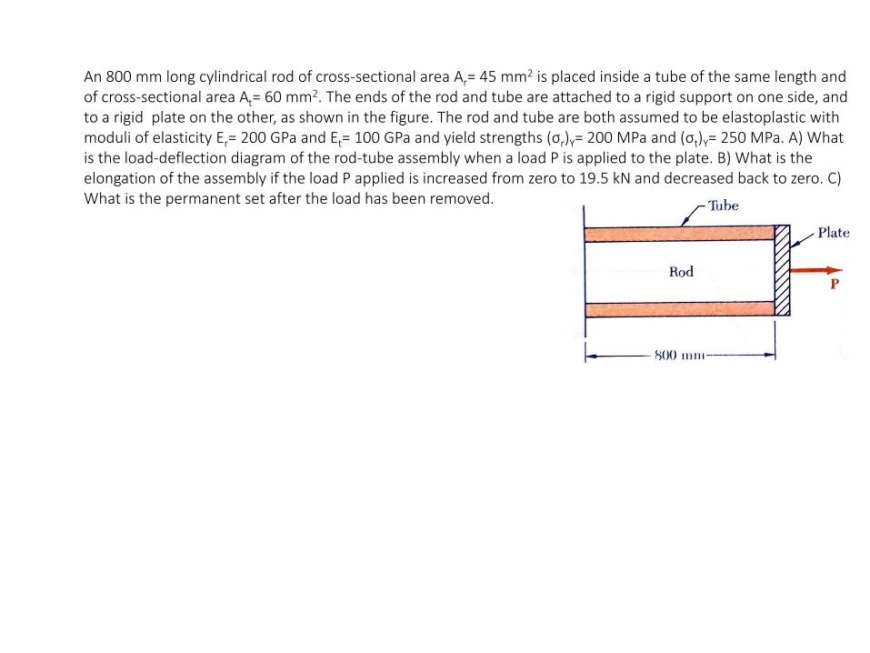
An 800 mm long cylindrical rod of cross-sectional area Ar= 45 mm2 is placed inside a tube of the same length and of cross-sectional area At= 60 mm2. The ends of the rod and tube are attached to a rigid support on one side, and to a rigid plate on the other, as shown in the figure. The rod and tube are both assumed to be elastoplastic with moduli of elasticity Er= 200 GPa and Et= 100 GPa and yield strengths (σr)Y= 200 MPa and (σt)Y= 250 MPa. A) What is the load-deflection diagram of the rod-tube assembly when a load P is applied to the plate. B) What is the elongation of the assembly if the load P applied is increased from zero to 19.5 kN and decreased back to zero. C) What is the permanent set after the load has been removed.
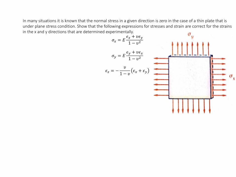
In many situations it is known that the normal stress in a given direction is zero in the case of a thin plate that is under plane stress condition. Show that the following expressions for stresses and strain are correct for the strains in the x and y directions that are determined experimentally.
𝜎𝑥 = 𝐸𝜖𝑥 + 𝜐𝜖𝑦
1 − 𝜐2
𝜎𝑦 = 𝐸𝜖𝑦 + 𝜐𝜖𝑥
1 − 𝜐2
𝜖𝑧 = −𝜐
1 − 𝜐𝜖𝑥 + 𝜖𝑦
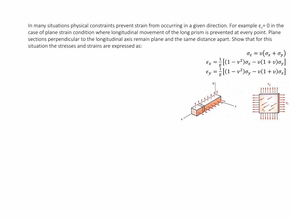
In many situations physical constraints prevent strain from occurring in a given direction. For example εz= 0 in the case of plane strain condition where longitudinal movement of the long prism is prevented at every point. Plane sections perpendicular to the longitudinal axis remain plane and the same distance apart. Show that for this situation the stresses and strains are expressed as:
𝜎𝑧 = 𝜐 𝜎𝑥 + 𝜎𝑦
𝜖𝑥 =1
𝐸1 − 𝜈2 𝜎𝑥 − 𝜐 1 + 𝜐 𝜎𝑦
𝜖𝑦 =1
𝐸1 − 𝜈2 𝜎𝑦 − 𝜐 1 + 𝜐 𝜎𝑥
A 20 mm square was scribed on the side of a large steel pressure vessel. The plane stress condition of the material after pressurization is shown. What is a) the change in the lengths of the sides and the percent change in the slope of the diagonal DB if E= 200 GPa and 𝜐= 0.3 ?
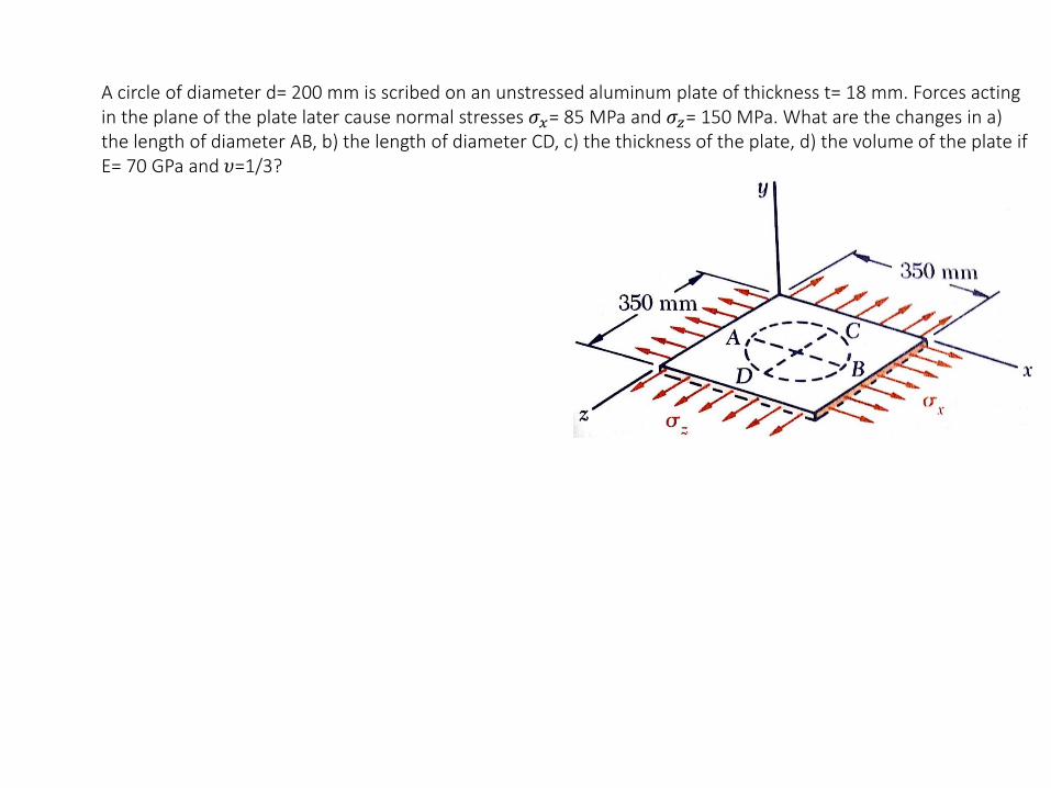
A circle of diameter d= 200 mm is scribed on an unstressed aluminum plate of thickness t= 18 mm. Forces acting in the plane of the plate later cause normal stresses 𝜎𝑥= 85 MPa and 𝜎𝑧= 150 MPa. What are the changes in a) the length of diameter AB, b) the length of diameter CD, c) the thickness of the plate, d) the volume of the plate if E= 70 GPa and 𝜐=1/3?