OFFICE OF THE MUNICIPAL CORPORATION GWALIOR,...
151
1 OFFICE OF THE MUNICIPAL CORPORATION GWALIOR, DIST-GWALIOR APPENDIX 2.18 TENDER DOCUMENT (FORM ‘F’ LUMPSUM TENDER FOR WATER SUPPLY RELATED WORKS) NIT Number and Date : MPGMC/6165/E-Tendering/Amrut/2017-18 Agreement Number and Date : ______________________________________ Name of Work : Water Supply Project – 2 of Municipal Corporation, Gwalior for, Under AMRUT, Name of the Contractor : ______________________________________ Probable Amount of Contract (Rs. In Figure) : Rs 28000 Lacs (Rs. In Words) : Rupees Two Hundred Eighty Crores Only. Contract Amount (Rs. In Figure) : ________________________________________ (Rs. In Words) : ________________________________________ Stipulated Period of Completion : 30 months including rainy season
Transcript of OFFICE OF THE MUNICIPAL CORPORATION GWALIOR,...

1
OFFICE OF THE MUNICIPAL CORPORATION GWALIOR, DIST-GWALIOR
APPENDIX 2.18
TENDER DOCUMENT
(FORM ‘F’ LUMPSUM TENDER FOR WATER SUPPLY RELATED WORKS)
NIT Number and Date : MPGMC/6165/E-Tendering/Amrut/2017-18
Agreement Number and Date : ______________________________________
Name of Work : Water Supply Project – 2 of Municipal
Corporation, Gwalior for, Under AMRUT,
Name of the Contractor : ______________________________________
Probable Amount of Contract
(Rs. In Figure) : Rs 28000 Lacs
(Rs. In Words) : Rupees Two Hundred Eighty Crores Only.
Contract Amount
(Rs. In Figure) : ________________________________________
(Rs. In Words) : ________________________________________
Stipulated Period of Completion : 30 months including rainy season

2
Table of Contents
Section No Particulars Page No
Section 1 NIT 03
Section 2
Instructions to Bidders (ITB) 06
Bid Data Sheet 12
Annexure-A to M
Annexure - A- Key Dates 14
Annexure –B- Affidavit 15
Annexure –C- Pre Qualification Criteria 16
Annexure –D- Special Eligibility Criteria 17
Annexure –E- Specifications 18
Annexure –F- Procedure for participating in E-tendering 19
Annexure –G- Joint Venture 21
Annexure –H- Organizational Details 23
Annexure –I- Technical Proposal 24
Annexure –J- Financial Bid 31
Annexure –K- Materials to be issued by department 32
Annexure –L- Letter of Acceptance (LOA) 33
Annexure –M- Performance Security 34
Section 3
Table of Clauses
Part-I General Conditions of Contract (GCC) 35
Contract Data 46
Annexure-N to W
Annexure –N- Drawings 49
Annexure –O- Detail of milestones 50
Annexure –P- Compensation of Delay 51
Annexure –Q- List of Equipment for Quality Control Lab 52
Annexure –R- Price Adjustment 53
Annexure –S- Bank Guarantee form for Mobilization Machinery Advance 54
Annexure –T- Bank Guarantee Form for Secured Advance 55
Annexure –U- Physical Completion Certificate 56
Annexure –V- Final Completion Certificate 57
Annexure –W- Salient Features of Labour laws 58
Part-II Special Conditions of Contract (SCC) 60
Section 4 Price Break-up Schedule 64
Section 5 Agreement Form 65
Annexure - X to Z
Section 6 Annexure –X- Billing Break-Up 66
Annexure –Y- Operation and Maintenance (Service Level Agreement) 67
Annexure-Z- Estimate for Operation and Maintenance

3
OFFICE OF THE MUNICIPAL CORPORATION- GWALIOR
Section – 1
Notice Inviting e-Tenders NIT No. MPGMC/6165/E-Tendering/Amrut/2017-18 Date: 22/04/2017
Online Lump Sum bids for the following works under “AMRUT” are invited from registered contractors and firms of repute fulfilling eligibility criteria:
1. Interested Bidder can view the NIT on website http://www.mpeproc.gov.in.and www.mpurban.gov.in
2. The Bid Document can be purchased only Online from 10:30 AM, 22 /04/2017 to 17:30 PM, 03/06/2017.
3. Amendment to NIT, if any, would be published on website only, and not in Newspaper.
The Bidder shall operate and maintain the water supply system for 5 years after successful completion
of the works as per Tender. The initial period of 2 years after completion shall be treated as Defect
Liability Period (DLP).
COMMISSIONER
MUNICIPAL CORPORATION, GWALIOR
S.No. Work
Probable
Amount
(In Rs.
Lakhs)
Completion
Period
(months)
1.0
Survey, Design, Construction and commissioning of water Supply Project – 2 of Gwalior Municipal Area including,
1. Design and construction of 160 MLD Water Treatment Plant
at Sharma Farm House and its all relevant component, complete in all respect.
2. Rehabilitation / Repair works I. Upgradation of Pumping machinery at Tighra to increase
output by 7 MLD. II. Rehabilitation of Existing Water Treatment Plant (two
numbers 68 MLD each) at Motijheel & repairing of existing clear water gravity main & Rising Main
3. Providing, Laying and Jointing of Clear Water Gravity Main/
Rising Main from various Tapping Point to OHTs/ GLSR, comprising of 200 mm to 1000 mm diameter, K9, DI pipe, having total length of 46.45 Km
4. Repairing of Existing Balancing reservoir at Motijheel 5. Repairing of Existing OHTs & GLSR. 6. Design & Construction of 43 nos. OHTs/ GSR of cumulative
capacity 40350 KL 7. Design & Construction of 7 nos. Sump of cumulative
capacity 3500kl and its all relevant component, complete in all respect.
8. Providing, Laying and Jointing of Distribution network comprising of 110 mm to 300 mm diameter, PE 100, PN 8, HDPE pipe, & diameter above 300mm of DI, K7, having total length of 777 Km, including fixing of House Service Connection & Installation of AMR compatible water meter, in Gwalior for strengthening and augmentation of water distribution network.
9. Provision of SCADA
28000
30 months
including rainy
season

4
Notice Inviting e-Tenders
OFFICE OF THE MUNICIPAL CORPORATION, - GWALIOR
NIT No. MPGMC/6165/E-Tendering/Amrut/2017-18 dated 22/04 /2017
Online lump-sum bids for the following works under “AMRUT” (estimated on UADD SOR w.e.f. 10/05/2012)
on Form “F” are invited from registered contractors and firms of repute fulfilling eligibility criteria:
S.N
o.
Name of the work Probable
amount
of
contract
(Rs. In
Lakhs)
Earnest
Money
Deposit
(EMD) (In
Rs Lakhs)
Cost of
Bid
Documen
t (In
Rupees)
Category of
Contractor
Time of
Comple
tion
1.0
Survey, Design, Construction and commissioning of water Supply Scheme of Gwalior Municipal Area including,
1. Design and construction of 160
MLD Water Treatment Plant at Sharma Farm House and its all relevant component, complete in all respect.
2. Rehabilitation / Repair works I. Upgradation of Pumping machinery
at Tighra to increase output by 7 MLD.
II. Rehabilitation of Existing Water
Treatment Plant (two numbers 68 MLD each) at Motijheel & repairing of existing clear water gravity main & Rising Main
3. Providing, Laying and Jointing of
Clear Water Gravity Main/ Rising Main from various Tapping Point to OHTs/ GLSR, comprising of 200 mm to 1000 mm diameter, K9, DI pipe, having total length of 46.45 Km
4. Repairing of Existing Balancing reservoir at Motijheel
5. Repairing of Existing OHTs & GLSR. 6. Design & Construction of 43 nos.
OHTs/ GSR of cumulative capacity 40350 KL
7. Design & Construction of 7 nos. Sump of cumulative capacity 3500kl and its all relevant component, complete in all respect.
8. Providing, Laying and Jointing of Distribution network comprising of 110 mm to 300 mm diameter, PE 100, PN 8, HDPE pipe, & diameter above 300mm of DI, K7, having total length of 777 Km, including fixing of House Service Connection & Installation of AMR compatible water meter, in Gwalior for strengthening and augmentation of water distribution network.
9. Provision of SCADA.
28000
140
50,000.00
Suitable class A of GoMP or equivalent in any State/Central Govt./ PSU
30
months
includin
g rainy
season.

5
1. All details relating to the Bid Document(s) can be viewed and downloaded free of cost from the website
mentioned in NIT.
2. Bid document can be purchased after making online payment of portal fees through Credit/Debit/Cash
Card/internet banking.
3. At the time of submission of the Bid the eligible bidder shall be required to:
i) pay the cost of Bid Document;
ii) deposit the Earnest Money;
iii) Submit a check list and
iv) Submit an affidavit.
Details can be seen in the Bid Data Sheet
4. ELIGIBILTY FOR BIDDERS:
(a) At the time of submission of the Bid the bidder should have valid registration with the Government of
Madhya Pradesh, PWD in appropriate class. However, such bidders who are not registered with the
Government of Madhya Pradesh and are registered with Central Government, State Government,
PSUs are eligible for submission of Bids.
(b) The bidder would be required to have valid registration with MPPWD in appropriate class at the time of
signing of the Contract.
(c) Failure to sign the contract by the selected bidder, for whatsoever reason, shall result in forfeiture of the
earnest money deposit.
5. Pre-qualification – Prequalification conditions, wherever applicable, are given in the Bid Data Sheet.
6. Special Eligibility - Special Eligibility Conditions, if any, are given in the Bid Data Sheet.
7. The Bid Document can be Purchased only Online from10:30 (time) 22 / 04 /2017 (date) to 17:30 (time) 03 /
06 / 2017 (date). Other key dates may be seen in Bid data sheet.
8. Amendment to NIT, if any, would be published on website only, and not in Newspaper.
COMMISSIONER
MUNICIPAL CORPORATION, GWALIOR

6
SECTION 2
INSTRUCTIONS TO BIDDERS (ITB)
A. GENERAL
1. SCOPE OF BID
The detailed scope of work, hereinafter referred to as “Work” is (1) “Design, Construction & Commissioning of water supply system and its operation and maintenance for a period of 5 years after completion of construction work. The initial period of 2 years after completion shall be treated as Defect Liability Period (DLP) . A brief description of project is as given below,
Background
(1) Water Supply Project:-
a) The population of Gwalior Municipal Corporation has increased tremendously. In 1991 GMC was
having a population of 6,90,765 souls. This population further increased to 8,27,026 souls as per 2001,
finally 11,59,032 souls as per 2011 census records of Gwalior Municipal Corporation. Recently 6 Wards
are added in the Gwalior Municipal Corporation. Existing Water supply system is not sufficient for
catering the future demand. This scheme is prepared for Gwalior Augmentation Water Supply Scheme
for year 2035.Supplying potable water @ 135 lpcd in Municipal area at a residual head of 10-12 m.
Project
MUNICIPAL CORPORATION, GWALIOR wants to execute water supply project in Municipal area to supply water @ 135 lpcd at a residual head of 10-12 m. The project report prepared by the MUNICIPAL CORPORATION, GWALIOR envisage, i) Providing, Laying and Jointing of Clear water Gravity Main/ Rising Main from various Tapping Point
to OHTs/ GLSR, comprising of 200 mm to 1000 mm diameter, K9, DI pipe, having total length of 46.45 Km
ii) Rehabilitation of Existing Water Treatment Plant (two numbers 68 MLD each) at Motijheel & repairing of existing Clear water rising/gravity pipeline.
iii) Up Gradation and Rehabilitation of Water Treatment Plant & Raw water Pumping Station at Tighara. iv) Construction of 43 nos. OHTs/ GSR of cumulative capacity 40350 KL & 7 nos. Sump cum pump
house of cumulative capacity 3500kl and its all relevant component, complete in all respect.
v) Providing, Laying and Jointing of Distribution network comprising of 110 mm to 300 mm diameter,
PE 100, PN 8, HDPE pipe, & diameter above 300mm of DI, K7, having total length of 777 Km,
including fixing of House Service Connection & Installation of AMR compatible water meter, in
Gwalior for strengthening and augmentation of water distribution network.
vi) Road reconstruction after laying of pipelines as per the original condition of road
vii) Provision of SCADA at WTPs and OHTs for monitoring.
The tender hereby is being invited for the execution of water supply project wherein the successful Bidder
has to augment the capacity of existing water supply system along with laying of the water distribution lines
in Gwalior Municipal Corporation. The essence of the project is:
b) Augmenting the existing capacity of water supply system of the town.
c) Supplying potable water @ 135 lpcd in Municipal area at a residual head of 10-12 m.
Therefore, (A) Water Supply:-
i) The bidder shall ensure house connections to house hold till the completion of construction works. For
making the individual water connection due considerations shall be given to the access to the house
hold and accordingly side lanes and back lanes are to be identified and used if possible. Also existing
useful water lines if found shall be suitably integrated with the proposed water Supply system.

7
ii) Bidder shall be examining the detail design and drawings and shall revalidate the same for preparation
of detailed construction drawings as per actual working conditions including usage of back lanes and
side lanes and minimum obstruction to existing utilities, road ways and railways.
On successful completion of the project as per best engineering practices the bidder shall operate and maintain the system for next 5 years. The initial 2 years period upon completion of construction work of this project shall be defect liability period (DLP). Therefore, strict adherence to the best design practice, quality construction and timely implementation is most important. The Detailed Project Report (DPR) for the work is available for viewing by the Bidder. However, it is clarified that the data and detailing of project in the DPR could be taken as base data only. The bidder is required to make his own assessment of work before bidding & the bidder shall not be entitled for claim on account of any deficiency / discrepancy in the data /information available in DPR. The Bidder is required to take approval for all detailed designs and drawings for all components of this project from Engineer-in-Chief, Urban Administration and Development, Bhopal.
2. General Quality of Work:
The work shall have to be executed in accordance with the drawings (prepared by Contractor and approved by the competent authority), technical specifications specified in the Bid Data Sheet/Contract Data, and shall have to meet high standards of workmanship, safety and security of workmen and works.
3. PROCEDURE FOR PARTICIPATION IN E-TENDERING
The procedure for participation in e-tendering is given in the Bid Data Sheet.
4. ONE BID PER BIDDER
4.1 The bidder can be an individual entity or a joint venture (if permitted as per Bid Data sheet). In case the J.V. is permitted, the requirement of joint venture shall be as per the Bid Data Sheet.
4.2 No bidder shall be entitled to submit more than one bid whether jointly or severally. If he does so, all bids wherein the bidder has participated shall stand disqualified.
4.3 In case of Bid submitted by the Joint Venture (Consortium of Bidders) only lead member should be essentially registered in appropriate class of Registration with the Government of Madhya Pradesh and are registered with Central Government, State Government, PSUs
5. Cost of Bidding
The bidder shall bear all costs associated with the preparation and submission of his bid, and no claim whatsoever for the same shall lie on the ULB.
6. Site Visit and examination of works
The bidder is advised to visit and examine the Site of Works and its surroundings and obtain for itself on its own responsibility all information that may be necessary for preparing the bid and entering into a contract for construction of the work. All costs shall have to be borne by the bidder.
B. BID DOCUMENTS
7. CONTENT OF BID DOCUMENTS
The Bid Document comprises of the following documents:
1. NIT with all amendments.
2. Instructions to Bidders,
3. Conditions of Contract:
i. Part I General Conditions of Contract and Contract Data; and
ii. Part II Special Conditions of Contract.
4. Specifications
5. Drawings,
6. Priced Bill of Quantities
7. Technical and Financial Bid
8. Letter of Acceptance
9. Agreement and
10. Any other document(s), as specified.

8
8. The bidder is expected to examine carefully all instructions, conditions of contract, the contract data, forms,
terms and specifications, bill of quantities, forms and drawings in the Bid Document. Bidder shall be solely
responsible for his failure to do so.
9. Pre-Bid Meeting (where applicable)
Wherever the Bid Data Sheet provides for pre-bid meeting:
9.1 Details of venue, date and time would be mentioned in the Bid Data Sheet. Any change in the
schedule of pre-bid meeting would be communicated on the website only, and intimation to bidders
would not be given separately.
9.2 Any prospective bidder may raise his queries and/or seek clarifications in writing before or during
the pre-bid meeting. The purpose of such meeting is to clarify issues and answer questions on any
matter that may be raised at that stage. The Employer may, at his option, give such clarifications as
are felt necessary.
9.3 Minutes of the pre-bid meeting including the list of the questions raised and the responses given
together with any response prepared after the meeting will be hosted on the website.
9.4 Pursuant to the pre-bid meeting if the Employer deems it necessary to amend the Bid Document, it
shall be done by issuing amendment to the online NIT.
10. Amendment of Bid Documents
10.1 Before the deadline for submission of bids, the Employer may amend or modify the Bid Documents
by publication of the same on the website.
10.2 All amendments shall form part of the Bid Document.
10.3 The Employer may, at its discretion, extend the last date for submission of bids by publication of the
same on the website.
C. PREPARATION OF BID
11. The bidders have to prepare their bids online, encrypt their Bid Data in the Bid Forms and submit Bid Seals
(Hashes) of all the envelopes and documents related to the Bid required to be uploaded as per the time
schedule mentioned in the key dates of the Notice Inviting e-Tenders after signing of the same by the Digital
Signature of their authorized representative.
12. DOCUMENTS COMPRISING THE BID
The bid submitted online by the bidder shall be in the following parts:
Part 1 – This shall be known as Envelope A and would apply for all bids. Envelop A shall contain the
following as per details given in the Bid Data Sheet:
i) Registration number or proof of application for registration and organizational details in format given
in the Bid Data sheet.
ii) Payment of the cost of Bid Document;
iii) Earnest Money; and
iv) An affidavit duly notarized.
Part 2 – This shall be known as Envelope B and required to be submitted only in works where pre-
qualification conditions and/or special eligibility conditions are stipulated in the Bid Data Sheet. Online
Envelop B shall contain a self-certified sheet duly supported by documents to demonstrate fulfillment of
pre-qualification conditions.
Part 3 – This shall be known as Envelope C and would apply to all bids. Envelop C shall contain financial
offer in the format prescribed enclosed with the Bid Data Sheet.
13. LANGUAGE
The bid as well as all correspondence and documents relating to the bid exchanged by the Bidder and the
Employer shall be in English or Hindi. Supporting documents and printed literature that are part of the Bid
may be in another language provided they are accompanied by an accurate translation of the relevant
passages in English. In such case, for the purposes of interpretation of the bid, such translation shall
govern.
14. TECHNICAL PROPOSAL
14.1 Only, in case of bids with pre-qualification conditions defined in the Bid data sheet, the Technical
Proposal shall comprise of formats and requirements given in the Bid Data Sheet.

9
14.2 All the documents / information enclosed with the technical proposals should be self attested and
certified by the Bidder. The Bidder shall be liable for forfeiture of his earnest money deposit, if any
document / information are found false/fake/untrue before acceptance of Bid. If it is found after
acceptance of the Bid, the sanctioning authority may at his discretion forfeit his performance
security/guarantee, security deposit, enlistment deposit and take any other suitable action.
15. FINANCIAL BID
i. The bidder shall have to quote rates in format referred in Bid Data sheet, in Lump sum, and not item
wise. If the bid is in absolute amount, overall percentage would be arrived at in relation to the NIT
amount. The overall percentage rate would apply for all items of work.
ii. Lump sum offer shall be quoted in figures as well as in words. If any difference in figures and words
found, lower of the two shall be taken as valid and correct.
iii. The bidder shall have to quote rates inclusive of all duties, taxes, royalties and other levies; and the
Employer shall not be liable for the same. Excise exemption on pipe shall be available as per norms.
iv. The material along with the units and rates, which shall be issued, if any, by the department to the
contractor, is mentioned in the Bid Data Sheet.
16. PERIOD OF VALIDITY OF BIDS
The bids shall remain valid for a period specified in Bid Data Sheet after the date of “close for biding” as
prescribed by the Employer. The validity of the bid can be extended by mutual consent in writing.
17. EARNEST MONEY DEPOSIT (EMD)
17.1 The Bidder shall furnish, as part of the Bid, Earnest Money Deposit (EMD), of the amount specified in the
Bid Data Sheet.
17.2 The EMD shall be in the form of Demand Draft/Fixed Deposit Receipt of a scheduled commercial bank,
issued in favour of the name given in the Bid Data Sheet. The Fixed Deposit Receipt shall be valid for six
months or more after the last date of receipt of bids. However, other forms of EMD may be allowed by the
employer by mentioning it in the Bid Data sheet.
17.3 Bid not accompanied by EMD shall be liable for rejection as non-responsive.
17.4 EMD of bidders whose bids are not accepted will be returned within ten working days of the decision on the bid.
17.5 EMD of the successful Bidder will be discharged when the Bidder has signed the Agreement and furnished
the Bank Guarantee of required value for Performance Security.
17.6 Failure to sign the contract by the selected bidder, for whatsoever reason, shall result in forfeiture of the
earnest money deposit.
D. SUBMISSION OF BID
18. The bidder is required to submit online bid duly signed digitally, and Envelop ‘A’ in physical form also at the
place prescribed in the Bid Data Sheet.
E. OPENING AND EVALUATION OF BID
19 PROCEDURE
19.1 Envelope ‘A’ shall be opened first online at the time and date notified and its contents shall be checked. In
cases where Envelop ‘A’ does not contain all requisite documents, such bid shall be treated as non-
responsive, and Envelop B and/or C of such bid shall not be opened.
19.2 Wherever Envelop ‘B’ (Technical Bid) is required to be submitted, the same shall be opened online at the
time and date notified. The bidder shall have freedom to witness opening of the Envelop ‘B’. Envelop ‘C’
(Financial Bid) of bidders who are not qualified in Technical Bid (Envelop ‘B’) shall not be opened.
19.3 Envelope ‘C’ (Financial Bid) of the qualified bidders shall be opened online at the time and date notified.
The bidder shall have freedom to witness opening of the Envelop ‘C’.
19.4 After opening Envelop ‘C’ all responsive bids shall be compared to determine the lowest evaluated bid.
19.5 The Employer reserves the right to accept or reject any bid, and to annul the biding process and reject all
the bids at any time prior to contract award, without incurring any liability. In all such cases reasons shall be
recorded.
19.6 The Employer reserves the right of accepting the bid for the whole work or for a distinct part of it.
20. Confidentiality
20.1 Information relating to examination, evaluation, comparison and recommendation of contract award shall
not be disclosed to bidders or any other person not officially concerned with such process until final decision
on the bid.

10
20.2 Any attempt by a bidder to influence the Employer in the evaluation of the bids or contract award decisions
may result in the rejection of its bid.
F. AWARD OF CONTRACT
21. Award of Contract
The Employer shall notify the successful bidder by issuing a ‘Letter of Acceptance’ that his bid has been
accepted.
22. Performance Security
22.1 Prior to signing of the Contract the bidder to whom LOA has been issued shall have to furnish performance
security of the amount, form and duration, etc. as specified in the Bid Data Sheet.
22.2 “In case if the employer finds from the Breakup of Design Build Prices, and/or Operation & Maintenance Prices and/or prices quoted for power consumption, that the prices indicated therein are unbalanced, the successful Bidder shall have to provide additional performance security as may be required by the employer for such unbalanced Bid prices.’’
23. Signing of Contract Agreement
23.1 The successful bidder shall have to furnish Performance security and sign the contract agreement within 15
days of issue of LOA.
23.2 The signing of contract agreement shall be reckoned as intimation to commencement of work. No separate
work order shall be issued by the Employer to the contractor for commencement of work.
23.3 In the event of failure of the successful bidder to submit Performance Security and additional performance
security if any or sign the Contract Agreement, his EMD shall stand forfeited without prejudice to the right of
the employer for taking action against the bidder.
24. CORRUPT PRACTICES
The Employer requires that bidders observe the highest standard of ethics during the procurement and
execution of contracts. In pursuance of this policy, the Employer:
i. may reject the bid for award if it determines that the bidder recommended for award has, directly or
through an agent, engaged in corrupt, fraudulent, collusive, or coercive practices in competing for the
Contract; and
ii. may debar the bidder if he is being blacklisted by any Department of State Government or GOI for non-
performance / sub standard execution or any other reason what so ever in similar type of works.
iii. may debar the bidder declaring ineligible, either indefinitely or for a stated period of time, to
participate in bids, if it at any time determines that the bidder has, directly or through an agent,
engaged in corrupt, fraudulent, collusive, or coercive practices in competing for, or in executing, a
contract.
For the purposes of this provision, the terms set forth above are defined as follows:
a. “corrupt practice” means the offering, giving, receiving, or soliciting, directly or indirectly,
anything of value to influence improperly the actions of another party;
b. “fraudulent practice” means any act or omission, including a misrepresentation, that knowingly
or recklessly misleads, or attempts to mislead, a party to obtain a financial or other benefit or to
avoid an obligation;
c. “coercive practice” means impairing or harming, or threatening to impair or harm, directly or
indirectly, any party or the property of the party to influence improperly the actions of a party;
d. “Collusive practice” means an arrangement between two or more parties designed to achieve
an improper purpose, including influencing improperly the actions of another party.
[End of ITB]

11
Bid Data Sheet
General
S.No. Particulars Data
1 Office inviting Tender Commissioner, Municipal Corporation,
Gwalior (M.P.)
2 NIT No MPGMC/6165/E-Tendering/Amrut/2017-18
3 Date of NIT
4 Bid document download
available from date & time
From 22.04.2017
10:30 Hrs
To 03.06.2017.
17:30 Hrs
5 Website link http://uadd.mpeprocurement.gov.in
For Section 1 - NIT
Clause
reference
Particulars Data
2 Portal fees As Applicable
3 Cost of bid document ( in the
form of Demand Draft)
Rs. 50,000
Cost of bid document
payable to
Municipal Corporation, Gwalior (M.P.)
Cost of bid document in favour
of
Commissioner, Municipal Corporation,
Gwalior (M.P.)
4 Affidavit Annexure B
5 Pre-qualifications required Yes
If Yes, details Annexure C
6 Special Eligibility No
If Yes, details Annexure D (Not applicable)
7 Key Dates Annexure A
For Section 2 - ITB
Clause
reference
Particulars Data
1 Name of work Water Supply Project- 2, Gwalior
(M.P.)
2 Specifications Annexure E
3 Procedure for participation in e-
tendering
Annexure F
4 Whether Joint-venture is allowed YES
If yes, requirement for Joint venture Annexure G
9 Pre bid meeting to held YES
If Yes, Date, Time & Place Date : 02/05/2017
Time from : 11:00 AM
Place : Directorate, Urban
Administration and
Development, Bhopal
12 Envelope –A containing :
i. Registration number or proof of
application for registration and
organizational details as per
Annexure ‘H’
ii. Cost of Bid Document
iii. EMD
iv. An affidavit duly notarized as per
Annexure –B
At the office of the
Commissioner, Municipal
Corporation, Gwalior (M.P.)
Before -17:30 hrs (05/06/2017)

12
Should reach in physical form
14 Envelope-B Technical Proposal Annexure – I and
Annexure – I (Format I-1 to I-5)
15 Envelope-C Financial Bid Annexure – J
Materials to be issued by the
department
16 Period of Validity of Bid 120 Days
17
Earnest Money Deposit Rs 140 .00 Lakhs
Forms of Earnest Money Deposit i. FDR/e-FDR
ii. Demand draft of scheduled
commercial bank
iii. Interest bearing securities of
post office
EMD valid for a period of Not less than 180 days
FDR (Fixed Deposit Receipt) must be
drawn in favour of
Commissioner, Municipal
Corporation, Gwalior (M.P.)
21 Letter of Acceptance (LoA) Annexure L
22 Amount of Performance Security 5% of the Tender Amount
Additional Performance Security, if
any
As per provision of clause
22.2 of ITB
Performance security in the format Annexure M
Performance security in favour of
Commissioner, Municipal
Corporation, Gwalior (M.P.)
Performance security valid up to Valid contract period plus 3
months
13
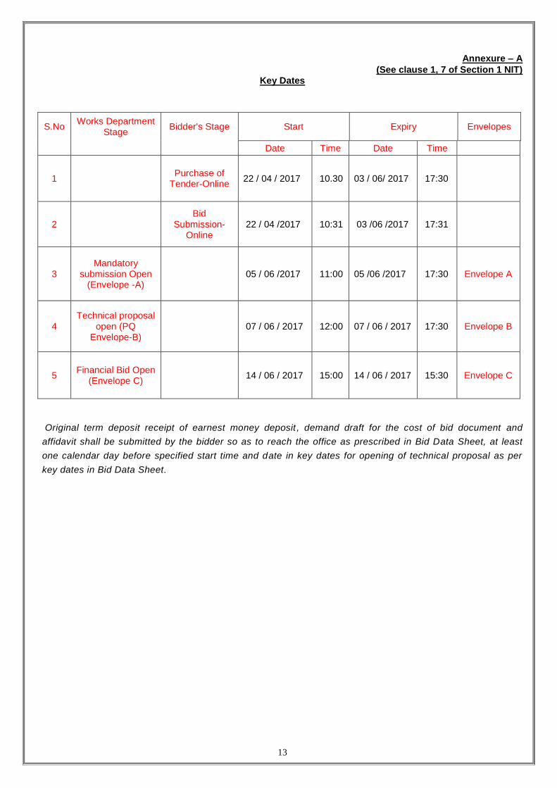
Annexure – A
(See clause 1, 7 of Section 1 NIT) Key Dates
S.No Works Department
Stage Bidder's Stage Start Expiry Envelopes
Date Time Date Time
1 Purchase of
Tender-Online 22 / 04 / 2017 10.30 03 / 06/ 2017 17:30
2 Bid
Submission-Online
22 / 04 /2017 10:31 03 /06 /2017 17:31
3 Mandatory
submission Open (Envelope -A)
05 / 06 /2017 11:00 05 /06 /2017 17:30 Envelope A
4 Technical proposal
open (PQ Envelope-B)
07 / 06 / 2017 12:00 07 / 06 / 2017 17:30 Envelope B
5 Financial Bid Open
(Envelope C) 14 / 06 / 2017 15:00 14 / 06 / 2017 15:30 Envelope C
Original term deposit receipt of earnest money deposit , demand draft for the cost of bid document and
affidavit shall be submitted by the bidder so as to reach the office as prescribed in Bid Data Sheet, at least
one calendar day before specified start time and date in key dates for opening of technical proposal as per
key dates in Bid Data Sheet.

14
Annexure – B
(See clause 3 of Section 1-NIT)
|| AFFIDAVIT ||
(To be contained in Envelope A)
(On Non Judicial Stamp of Rs. 1000)
I/we _______________________________________________________ who is/ are
_______________________ (status in the firm/ company) and competent for submission of the affidavit on behalf
of M/S ______________________ (contractor) do solemnly affirm an oath and state that:
I/we are fully satisfied for the correctness of the certificates/records submitted in support of the following
information in bid documents which are being submitted in response to notice inviting e-tender No.
______________ for __________________________ (name of work) dated _______ issued by the
________________ (name of the ULB).
I/we are fully responsible for the correctness of following self certified information/ documents and
certificates:
1. That the self certified information given in the bid document is fully true and authentic.
2. That:
a. Term deposit receipt deposited as earnest money, demand draft for cost of bid document and other
relevant documents provided by the Bank are authentic.
b. Information regarding financial qualification and annual turn-over is correct.
c. Information regarding various physical qualifications is correct.
3. No close relative of the undersigned and our firm/company is working in the department.
OR
Following close relatives are working in the department:
Name _______________ Post ____________________ Present Posting ___________
Signature with Seal of the Deponent (bidder)
I/ We, _____________________ above deponent do hereby certify that the facts mentioned in above paras
1 to 3 are correct to the best of my knowledge and belief.
Verified today _____________ (dated) at ______________ (place).
Signature with Seal of the Deponent (bidder)
15
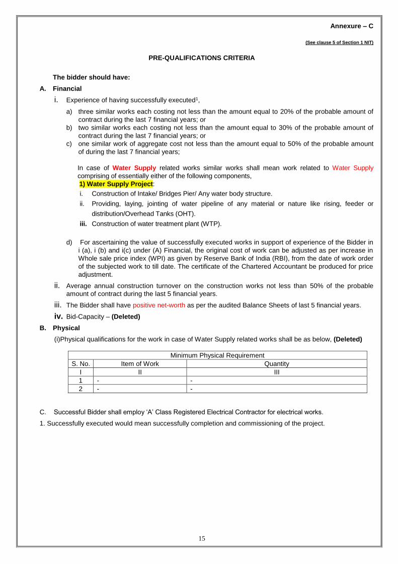
Annexure – C
(See clause 5 of Section 1 NIT)
PRE-QUALIFICATIONS CRITERIA
The bidder should have:
A. Financial
i. Experience of having successfully executed1,
a) three similar works each costing not less than the amount equal to 20% of the probable amount of
contract during the last 7 financial years; or
b) two similar works each costing not less than the amount equal to 30% of the probable amount of
contract during the last 7 financial years; or
c) one similar work of aggregate cost not less than the amount equal to 50% of the probable amount
of during the last 7 financial years;
In case of Water Supply related works similar works shall mean work related to Water Supply
comprising of essentially either of the following components,
1) Water Supply Project:
i. Construction of Intake/ Bridges Pier/ Any water body structure.
ii. Providing, laying, jointing of water pipeline of any material or nature like rising, feeder or
distribution/Overhead Tanks (OHT).
iii. Construction of water treatment plant (WTP).
d) For ascertaining the value of successfully executed works in support of experience of the Bidder in
i (a), i (b) and i(c) under (A) Financial, the original cost of work can be adjusted as per increase in
Whole sale price index (WPI) as given by Reserve Bank of India (RBI), from the date of work order
of the subjected work to till date. The certificate of the Chartered Accountant be produced for price
adjustment.
ii. Average annual construction turnover on the construction works not less than 50% of the probable
amount of contract during the last 5 financial years.
iii. The Bidder shall have positive net-worth as per the audited Balance Sheets of last 5 financial years.
iv. Bid-Capacity – (Deleted)
B. Physical
(i)Physical qualifications for the work in case of Water Supply related works shall be as below, (Deleted)
Minimum Physical Requirement
S. No. Item of Work Quantity
I II III
1 - -
2 - -
C. Successful Bidder shall employ ‘A’ Class Registered Electrical Contractor for electrical works.
1. Successfully executed would mean successfully completion and commissioning of the project.

16
Annexure – D
(See clause 6 of Section 1 NIT)
SPECIAL ELIGIBILITY CRITERIA

17
Annexure – E
(See clause 2 of Section 2-ITB &
clause 10 of GCC)
Specifications
(Enclosed)

18
ANNEXURE-F
(See clause 3 of Section 2-ITB)
Procedure for participation in e-Tendering
1. Registration of Bidders on e-Tendering System
All the PWD registered bidders are already registered on the new e-procurement portal
https://www,mpeproc.gov .in. The user id will be the contractor ID provided to them from MP Online. The
password for the new portal has been sent to the bidders registered email ID. For more details may contact
M/s___________ Tata consultancy Services Corporate Block, 5th floor, DB city Bhopal-462011, email id:
[email protected]. Helpdesk phone numbers are available on website.
2. Digital Certificate:
The bids submitted online should be signed electronically with a class III Digital Certificate to establish the
identity of the bidder submitting the bid online. The bidders may obtain class III Certificate issued by an
approved certifying Authority authorized by the controller of certifying Authorities, government of India. A
class III digital Certificate is issued upon receipt of the required proofs along with an application. Only upon
the receipt of the required documents, a digital certificate can be issued. For details please visit cca.gov.in.
Note:
i. It may take up to 7 working days for issuance of class III digital certificate; hence the bidders are
advised to obtain the certificate at the earliest. Those bidders who already have valid class III digital
certificate need not obtain another Digital Certificate for the same.
The bidders may obtain more information and the APPLICATION FORM REQUIRED TO BE
SUBMITTED FOR THE ISSUANCE OF DIGITAL CERTIFICATE FROM cca.gov.in.
ii Bids can be submitted till bid submission end date. Bidder will require digital signature while bid
submission. The digital certificate issued to the authorized user of a partnership firm/Private limited
company/Public Limited Company and user for online bidding will be considered as equivalent to a no-
objection certificate/power of attorney to that user.
In case of Partnership firm, majority of the partners have to authorize a specific individual through
authority letter signed by majority of partners of the firm.
In case of Private Limited company, Public Limited Company, the Managing Director has to authorize a
specific individual through Authority Letter. Unless the certificate is revoked, it will be assumed to
represent adequate authority of the specific individual to bid on behalf of the organization for online
bids as per Information Technology Act 2000. This Authorized User will be required to obtain a digital
certificate. The Digital Signature executed though the use of the responsibility of
Management/Partners of the concerned firm to inform the Certifying Authority, if the authorized user
changes, and applies for a fresh Digital Certificate for the new Authorized user.
3. Set Up of Bidder’s Computer System:
In order for a bidder to operate on the e-tendering System, the Computer system of the bidder is required to
be set up for Operating System, Internet Connectivity, Utilities, Fonts, etc. The details are available at
https://www.mpeproc.gov.in.

19
4. Key Dates:
The bidders are strictly advised to follow the time schedule (Key dates) of the bid of their side for tasks and
responsibilities to participate in the bid, as all the stages of each bid are locked before the tart time and date
and after the end time and date for the relevant stage if the bid as set by the Department.
5. Preparation and Submission of Bids
The bidders have to prepare their online, encrypt their bid data in the Bid forms and submit Bid of all the
envelopes and documents related to the Bid required to be uploaded as per the time schedule mentioned in
the key dates of the notice inviting e- Tenders after singing of the same by the Digital Signature of their
authorized representatives.
6. Purchase of Bid Document
For purchasing of the bid document bidders have to pay Service Charge online ONLY which is Rs. [as per
Bid Data Sheet]. Cost of Bid document is separately mentioned in the detailed NIT. The Bid Document shall
be available for purchase to concerned eligible bidders immediately after online release of the bids and upto
scheduled time and date as set in the key dates. The payment for the cost of bid document shall be made
online through Debit/Credit card. Net banking or NeFT Challan through the payment gateway provided on
the portal.
7. Withdrawal, Substitution and Modification of Bids
Bidder can withdraw and modify the bid before submission end date.

20
ANNEXURE-G
(See clause 4 of Section 2-ITB)
JOINT VENTURE (J.V.) If J.V. is allowed following conditions and requirements must be fulfilled –
1. Number of partners in a Joint Venture shall not exceed 3 (three). The partners shall comply with the following requirements :
a. One of the partners shall be nominated as being Lead Partner, and this authorization shall be evidenced by submitting a power of attorney signed by legally authorized signatories of all the partners;
b. The bid and, in case of successful bid, the Agreement, shall be signed so as to be legally binding on all partners; c. The partner in charge shall be authorized to incur liabilities and receive instructions for and on behalf of any and all
partners of the joint venture and the entire execution of the contract, including payment, shall be done exclusively with the partner in charge;
d. All the partners of the joint venture shall be liable jointly and severally for the execution of the contract in accordance with the contract terms, and a statement to this effect shall be included in the authorization mentioned under [c] above, as well as in the bid and in the Agreement [in case of successful bid];
e. Bidder shall submit the joint venture agreement (on Rs 1000/- Non-judicial stamp paper) indicating precisely the role and responsibilities of all the members of JV in respect of planning, design, construction equipment, key personnel, work execution, and financing of the project including operation and maintenance of the works. All members of JV should have active participation in execution during the currency of the contract. This should not be varied/modified subsequently without prior approval of the employer;
f. a copy of the Joint Venture Agreement entered into by the partners shall be submitted with the bid. g. The joint venture agreement shall be registered at the time of agreement, so as to be legally valid and binding on
all partners. 2. All the partners should meet out the minimum qualifying criteria required for the bid and collectively must meet the
criteria specified in full. Failure to comply with this requirement will result in rejection of the joint venture’s bid. 3. The performance security of joint venture shall be in the name of the partner Lead partner/joint venture. 4. Attach the power of attorney of the partners authorizing the Bid signatory(ies) on behalf of the joint venture 5. An individual Bidder cannot at the same time be member of a Joint Venture applying for this Bid. Further, a
member of a particular Bidder Joint Venture cannot be member of any other Bidder Joint Venture applying for this bid.
6. A copy of the Joint Venture agreement entered into by the partners made on Rs 1000/- Non-judicial stamp duly notarized shall be submitted with the bid. However at the time of agreement bidder shall get the joint venture agreement registered, so as to be legally valid and binding on all partners.
7. Furnish details of participation proposed in the joint venture as below: PARTICIPATION DETAILS FIRM ‘A’ (Lead partner) FIRM ‘B’ FIRM ‘C’ Financial Name of the Banker(s) Planning Construction Equipment Key personnel Execution of Work (Give details on contribution of each)
7. The partners of J.V. should satisfy the qualification criteria as below,
a. The Lead Partner must have the share of 51% in the J.V. b. The other partner(s) must have a share of minimum 25% in the J.V. c. The lead partner and the other partners must also meet 51% and 26% of the all qualification criteria
respectively except for the requirement of work experience described in Annexure 'C'. However both the partners must satisfy the full (100%) qualification criteria jointly. For this purpose the qualification of individual partners shall be added (for annual average turnover, net worth and for Bid Capacity Only).
8. For the meeting the minimum qualification criteria of experience of similar nature work,
i. Out of 3 similar works of value more than 20% of PAC, at least 2 works must be done by lead
partner and one work to be done by other partner,
Or
ii. Out of 2 similar works of value more than 30% of PAC, at least 1(one) work must be done by
lead partner and 1 (one) work to be done by other partner,
Or
iii In case of one similar work of value more than 50% of PAC the lead partner must satisfy the
criteria, However the other partner must satisfy the criteria in (i) above i.e., at least one work of 20%
of PAC.

21
ANNEXURE-H
(See clause 12 of Section 2 ITB & clause 4 of GCC)
ORGANIZATIONAL DETAILS
(To be enclosed with technical proposal)
S.No. Particulars Details
1. Registration No. issued by centralized
registration system of Govt. of MP or proof of
application for registration
(If applicable, scanned copy of proof of application
for registration to be uploaded)
2. Valid registration of Bidder in appropriate class
through centralized registration of Govt. of MP
Registration no………………. date……….
(Scanned copy of Registration to be uploaded)
3. Name of Organization/ Individual
4. Entity of Organization
Individual/ Proprietary Firm/ Partnership Firm
(Registered under Partnership Act)/ Limited
Company (Registered under the Companies
Act–1956)/ COUNCIL
5. Address of Communication
6. Telephone Number with STD Code
7. Fax Number with STD Code
8. Mobile Number
9. E-mail Address for all communications
Details of Authorized Representative
10. Name
11. Designation
12. Postal Address
13. Telephone Number with STD Code
14. Fax Number with STD Code
15. Mobile Number
16. E-mail Address
Note: In case of partnership firm and limited company certified copy of partnership deed/ Articles of Association
and Memorandum of Association along with registration certificate of the company shall have to be
enclosed.
Signature of Bidder with Seal
Date: _____________

22
Annexure – I
(See clause 14 of Section 2 of ITB)
Envelope – B, Technical Proposal
Technical Proposal shall comprise the following documents:
S.No. Particulars Details to be submitted
1 Experience - Financial and Physical Annexure – I (Format : I - 1)
2 Annual Turnover Annexure – I (Format : I - 2)
3 List of technical personnel for the key
positions
Annexure – I (Format: I - 3)
4 List of Key equipments/ machines for
quality control labs
Annexure – I (Format: I - 4)
5 List of Key equipments/ machines for
construction work
Annexure – I (Format: I – 5)
Note:
1. Technical Proposal should be uploaded duly page numbered and indexed.
2. Technical Proposal uploaded otherwise will not be considered.

23
Annexure – I (Format: I-1)
(See clause 15 of Section 2 of ITB
FINANCIAL & PHYSICAL EXPERIENCE DETAILS
A. Financial Requirement
The bidder should have completed either of the below:
a) three similar works each costing not less than the amount equal to 20% of the probable amount of contract
during the last 7 financial years; or
b) two similar works each costing not less than the amount equal to 30% of the probable amount of contract
during the last 7 financial years; or
c) one similar work of aggregate cost not less than the amount equal to 50% of the probable amount of
contract during the last 7 financial years;
To be filled in by the contractor:
i. Details of successfully completed similar works shall be furnished in the following format.
ii. Certificate duly signed by the employer shall also be enclosed for each completed similar work.
Agreement
Number & Year
Name of
Work
Date of
Work Order
Date of
Completion
Amount of
Contract
Employer's
Name and
Address
Existing commitments – (Value of ‘C’ for Bid Capacity formula) (deleted)
Agreement
Number &
Year
Name of
Work
Date of
Work
Order
Date of
Completion
Amount of
Contract
Amount Employer's
Name and
Address
B. Physical Requirement:
Execution of similar items of work in any one financial year during the last 3 financial years should
not be less than the minimum physical requirement fixed for the work.
S.No. Particulars
Actual Quantity Executed
(To be filled in by the contractor)
Year – 1 Year – 2 Year – 3
1 Physical qualification requirement No
2
3
Note: 1. Similar works: As described and detailed in Clause ‘A’ of Annexure ‘C’

24
Annexure – I (Format: I-2)
(See clause 14 of Section 2 of ITB
ANNUAL TURN OVER
Requirement:
Average annual construction turnover on the construction works not less than 50% of the probable
amount of contract during the last 5 financial years;
To be filled in by the contractor:
Financial Year Payments received for contracts in progress or completed
1
2
3
4
5
Note:
i. Annual turnover of construction should be certified by the Chartered Accountant.
ii. Audited balance sheet including all related notes, and income statements for the above financial years to be
enclosed.
Bid Capacity (Deleted)
Applicants who meet the minimum qualifying criteria in the evaluation as stated above are to be evaluated further
for bid capacity as under:
Bid Capacity = (2.0 A X B) - C
Where,
A = Maximum value of civil engineering works executed in any one year during the
last five year (10% weightage per year shall be given to bring the value of work executed at
present price level)
B = Proposed contract period in years.
C = Amount if work in hand at present.

25
Annexure – I (Format: I-3)
(See clause 14 of Section 2 of ITB
& Clause 6 of ITB
LIST OF TECHNICAL PERSONNEL FOR THE KEY POSITIONS
Minimum Requirement Available with the bidder
S.N
o.
Ke
y P
ositio
n
Min
imu
m
requ
ire
me
nt
Qu
alif
ica
tion
Ag
e
Sim
ilar
wo
rk
expe
rien
ce
Tota
l W
ork
Exp
erie
nce
S.N
o.
Na
me
of
Pe
rso
nn
el
Ke
y P
ositio
n
Qu
alif
ica
tion
Ag
e
Sim
ilar
wo
rk
expe
rien
ce
Tota
l W
ork
Exp
erie
nce
1 PM 1 B.E. Civil <45 Year
> 5 Year
>20 Year
2 DPM 4 B.E. Civil
< 40 Year
> 5 Year
>15 Year
3 Site Engineer 25 B.E/Dipl..
<35 Year
> 2 Year
>10 Year
4 QS 2 B.E. Civil
<35 Year
> 5 Year
>10 Year
5 Surveyor 2 Dipl. <35 Year
> 5 Year
>10 Year
6 Mechanical Engineer 1 B.E.
<35 Year
> 5 Year
>10 Year
7 Lab Incharge 1 B.E/Dipl
<35 Year
> 5 Year
>10 Year

26
Annexure – I (Format: I-4)
(See clause 14 of Section 2 of ITB)
List of Key Equipments/ Machines for Quality Control Labs
The Contractor shall be required to carry out all mandatory quality control tests as per specifications of various
items of work under the project. The Contractor should demonstrate his capacity with respect to availability of key
equipments / machines required for carrying out mandatory tests under project. All the materials i.e. pipes, pumps,
valves , specials etc. , to be procured under this contract shall be as per relevant IS codes of practice and inspected
by 3rd party. The certificate in this regard shall be furnished by the Contractor.
For monitoring the quality of treated water the Laboratory as per Appendix 15.7 and 15.8 of Manual on Water
supply and Treatment (CPHEEO) with up to date amendments if any.
Apart from above for the various civil works following Equipments/ Machines shall be required for quality
control.
Minimum requirement Available with the Bidder
S.
No.
Name of Equipment/ Machinery Quantity Name of Equipment/
Machinery
Quantity
1 Digging tools like pick axe,
shovel, etc.
One set
2 IS Sieves Nos. with lid and pan
(90 mm, 80 mm, 63 mm,
53 mm, 45 mm, 37.5 mm,
26.5 mm, 19 mm, 13.2 mm,
11.2 mm, 9.5 mm, 4.75 mm,
2.8 mm, 5.6 mm, 3.35 mm,
2.36 mm, 600 Micron,
425 Micron, 300 Micron,
150 Micron, 180 Micron,
90 Micron and 75 Micron)
ONE
SET
3 Sand Pouring Cylinder with tray
complete for field Density test
One set
4 Speedy moisture meter complete
with chemicals
One set
5 Straight Edges 3.00 meter width Two set
6 Liquid Limit and plastic limit
testing apparatus complete with
water bottle and glass wares
One set
7 Electronic/digital balance 5 kg One no.
8 Pan balance with weight box, 5
kg.
One no.
9 Slump cone Two no.
10 Concrete cube moulds (150 mm
X 150mm)
Twelve
no.
11 Free swelling index test
Apparatus
Six no.
12 Flakiness and elongation testing
gauges
Two no.
13 Water absorption test apparatus One no.
14 Specific gravity test apparatus One no.
15 B.S. compaction apparatus One no.
16 Proving rings One
each
17 Glass ware One set
18 Auto level and staff Three
nos.
19 Rapid moisture meter One no.
20 Post Hole Auger with
extensions
One set
21 Measuring tape, spatula,
glassware, porcelain dish, pestle
One set

27
mortar
22 Standard Proctor Density Test
Apparatus with rammer
One set
23 Electronic/digital balance 1kg
with the least count of 0.01 gm
One set
24 Camber Board Two no.
25 Core Cutter (10 cm dia.) 10cm/
15cm height complete with dolly
and Hummer.
One set
26 CBR Testing machine One no.
27 Oven (ambient to 200°C) One no.
28 Digital Thermometers Three o.
Aggregate Soundness test
apparatus
One no.
30 Concrete cube testing machine One no.
31 First aid box One no.
32 Sampling Pipette One no.
33 Balance One no.
34 Dial Gauges Six No.
35 Thickness gauge One set
36 Water still (4 ft.) One no.
37 A.I.V. testing equipment One no.
The above list of essential equipment for quality control is for guidance and is not complete.
Other apparatus and equipment as desired/required by the Engineer-in-Charge shall be procured by the Contractor

28
Annexure – I (Format: I-5)
(See clause 14 of Section 2 of ITB)
LIST OF EQUIPMENTS / MACHINES FOR CONSTRUCTION WORK
The Contractor shall carryout the construction work in such a way that the requirements of the
specifications of each item of work under the project are fully satisfied. For achieving the quality
parameters as per the specifications, the contractor shall be required to deploy appropriate
machinery and equipment for carrying out the work. In this section, the Bidder is required to
demonstrate his capacity with respect to Key equipments and machinery that are required to
carry out this work successfully.
Minimum requirement Available with the Bidder
S. No. Name of
Equipment/
Machinery
Quantity Name of
Equipment/
Machinery
Quantity
1 Dumper 6
2 Excavator/JCB 6
3 Crane/ Hydra 2
4 Mixer with weigh
Batcher
10
5 Tractor with Trolley 10
6 Total Station 3
7 Leveling Staff 3 Set
8 Earth Compactor 5
9 Road Cutter 2
10 Vibrator (Plate &
Needle)
10

29
Annexure – J
(See clause 14 of Section 2 of ITB)
FINANCIAL BID
(TO BE CONTAINED IN ENVELOPE C)
APPENDIX: 2.18
(See Paragraph 2.091)
TENDER FOR A LUMP SUM CONTRACT:
/We do hereby TENDER to execute the whole of the work described in the drawing and according to the annexed specification for the sum of Rupees (in figures) ……………………………………………..…………………….… (in words)……………………………………………………… (To be quoted in lump sum online and to be expressed both in words and figures). I/We have visited the site of work and am/are fully aware of all the difficulties and conditions likely to affect carrying out the work. I/We have fully acquainted myself/ourselves about the conditions in regard to accessibility of site and quarries/kilns, nature and the extent of ground, working conditions including stacking of materials, installation of tools and plant conditions effecting accommodation and movement of labour etc. required for the satisfactory execution of contract.
Should this bid be accepted, I/We hereby agree to abide by and fulfill all the terms and provisions of the
said conditions of contract annexed hereto so far as applicable, or in default thereof to forfeit and pay to the
Commissioner, Gwalior Municipal Corporation, Madhya Pradesh or his successors in office the sums of money
mentioned in the said conditions.
Note: i. Only Lump sum cost for the scope of work given therein shall be quoted. ii. Lump sum offer shall be quoted in figures as well as in words. If any difference in figures and words found lower
of the two shall be taken as valid and correct Price. If the bidder is not ready to accept such valid and correct Price and declines to furnish performance security and sign the agreement his earnest money deposit shall be forfeited.
iii. In case the price is not given by a bidder, his bid shall be treated as non-responsive. iv. All duties, taxes, and other levies payable by the bidder shall be included in the lump sum offer given by the
bidder. Only Exemption in Excise duty shall be available as per norms.
Dated______________
Bidder's Signature___________________
Address_______________________________
The above said TENDER is hereby accepted by me on behalf of the Corporation on the Day of _______________
The_________________2017_______
* To be expressed in words and figure)
SECURITIES
_______________________________________________________________________________
Name Address Occupation or Remarks
Profession
The above bid is hereby accepted by me on behalf of the (Name of ULB) on dated the _________ day of
__________ 20__
Commissioner
Municipal Corporation, Gwalior
District Gwalior (M.P.)

30
Annexure – K
(See clause 15 of Section 2 of ITB)
MATERIALS TO BE ISSUED BY THE DEPARTMENT (Deleted)

31
Annexure – L
(See clause 21 of Section 2 of ITB)
LETTER OF ACCEPTANCE (LOA)
No. _______________ Dated: ___________
To,
M/s. ___________________________
(Name and address of the contractor)
Subject: _________________________________
(Name of the work as appearing in the bid for the work)
Dear Sir (s),
Your bid for the work mentioned above has been accepted on behalf of the (Name of ULB) at your bided
lump sum offer as per scope of work given therein.
You are requested to submit the following within 15 (Fifteen) days from the date of issue of this letter:
a. The performance security/ performance guarantee of Rs. __________ (in figures) (Rupees
____________________________________________ in words) only being 5% of the capital cost of the project.
The performance security shall be in the shape of Term Deposit Receipt/ Bank Guarantee of any nationalized /
schedule commercial bank valid up to valid up to Valid Contract Period Plus three months.
(In prescribed Format as per Annexure – M)
b. The Additional Performance Security/ Additional Performance Guarantee of Rs. __________ (in figures) (Rupees
____________________________________________ in words) only. The performance security shall be in the
shape of Term Deposit Receipt/ Bank Guarantee of any nationalized / schedule commercial bank valid up Valid
Contract Period Plus three months. (In prescribed Format as per Annexure – M)
c. Duly signed Contract Agreement in Agreement Form as prescribed in Section – 5
Please note that
(i) the time allowed for carrying out the work as entered in the bid is __________ months including/excluding rainy
season, shall be reckoned from the date of signing the Contract Agreement and
(ii) the performance security/ performance guarantee of Rs. __________ (in figures) (Rupees
____________________________________________ in words) only being 5% of O & M and electrical cost, to be
submitted before the completion of design built component valid up to 3 months beyond the end of O&M period. The
performance security shall be in the shape of Term Deposit Receipt/ Bank Guarantee of any nationalized / schedule
commercial bank. (In prescribed Format as per Annexure – M)
Signing the contract agreement shall be reckoned as intimation to commencement of work and no separate letter for
commencement of work is required.
Therefore, after signing of the agreement, you are directed to contact Engineer-in-charge within 14days for
taking the possession of site and necessary instructions to start the work.
Yours faithfully,
Commissioner
Municipal Corporation, Gwalior

32
Annexure – M
(See clause 22 of Section 2 of ITB)
PERFORMANCE SECURITY
To
_______________________________ [Name of Employer]
_______________________________
_______________________________ [Address of Employer]
______________________________
WHEREAS_______________________ [name and Address of Contractor]
(Hereinafter called “the Contractor”) has undertaken, in pursuance of Letter of Acceptance No._______________
Dated _________to execute_________[Name of Contract and brief description of Works] (herein after called “the Contract”).
AND WHEREAS it has been stipulated by you in the said Contract that the contractor shall furnish you with a Bank Guarantee by a recognized bank for the sum specified therein as security for compliance with his obligation in accordance with the contract;
AND WHREREAS we have agreed to give the Contractor such a Bank Guarantee:
NOW THEREFORE we hereby affirm that we are the Guarantor and responsible to you on behalf of the Contractor, up to a total of ___________[amount of Guarantee]*__________ (in words), such sum being payable in the types and proportions of currencies in which the contract price is payable, and we undertake to pay you, upon your first written demand and without cavil or argument, any sum or sums within the limits of_____________[ amount of Guarantee] as aforesaid without your needing to prove or to show grounds or reasons for your demand for the sum specified therein.
We hereby waive the necessity of your demanding the said debt from the contractor before presenting us with the demand.
We further agree that no change or addition to or other modification of the terms of the Contract of the Works to be performed there under or of any of the Contract documents which may be made between you and the Contractor shall in any way release us from any liability under this Guarantee, and we hereby waive notice of any such change, addition or modification.
This Guarantee shall be valid until 3(three) months from the date of expiry of the Defect Liability Period.
Signature, Name and Seal of the Guarantor________________________________________________
Name of Bank__________________________________________________________________________
Address_______________________________________________________________________________
Phone No., Fax No., E-mail Address, of Signing Authority___________________________________
Date__________________________________________________________________________________
* An amount shall be inserted by the Guarantor, representing the percentage the Contract Price specified in the Contract including additional security for unbalanced Bids, if any and denominated in Indian Rupees.

33
SECTION 3
Conditions of Contract
Part – I General Conditions of Contract [GCC]
Table of Clauses of GCC
Sno Particulars S. No. Particulars
A. General 21 Payments for Variations and / or Extra
Quantities
1 Definitions 22 No compensation for alterations in or
restriction of work to be carried out.
2 Interpretations and Documents 23 No Interest payable
3 Language and Law 24 Recovery from Contractors
4 Communications 25 Tax
5 Subcontracting 26 Check Measurements
6 Personnel 27 Termination by Engineer in charge
7 Force Majeure 28 Payment upon Termination
8 Contractor's Risks 29 Performance Security
9 Liability For Accidents To Person 30 Security Deposit
10 Contractor to Construct the Works 31 Price Adjustment
11 Discoveries 32 Mobilization and Construction Machinery
Advance
12 Dispute Resolution System 33 Secured Advance
B. Time Control 34 Payment certificates
13 Programme E. Finishing the Contract
14 Extension of Time 35 Completion of Certificate
15 Compensation for Delay 36 Final Account
16 Contractor’s quoted percentage F. Other Conditions of Contract
C. Quality Control 37 Currencies
17 Tests 38 Labour
18 Correction of Defects noticed during
the Defect Liability Period
39 Compliance with Labour Regulations
D. Cost Control 40 Audit and Technical Examination
19 Variations - Change in original
Specifications, Designs, Drawings etc.
41 Death and Permanent Invalidity of
Contractor
20 Extra Items 42 Jurisdiction
43 Monthly RA bills
34
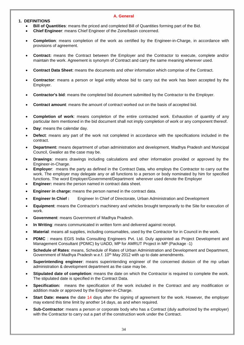
A. General
1. DEFINITIONS
Bill of Quantities: means the priced and completed Bill of Quantities forming part of the Bid.
Chief Engineer: means Chief Engineer of the Zone/basin concerned.
Completion: means completion of the work as certified by the Engineer-in-Charge, in accordance with
provisions of agreement.
Contract: means the Contract between the Employer and the Contractor to execute, complete and/or
maintain the work. Agreement is synonym of Contract and carry the same meaning wherever used.
Contract Data Sheet: means the documents and other information which comprise of the Contract.
Contractor: means a person or legal entity whose bid to carry out the work has been accepted by the
Employer.
Contractor's bid: means the completed bid document submitted by the Contractor to the Employer.
Contract amount: means the amount of contract worked out on the basis of accepted bid.
Completion of work: means completion of the entire contracted work. Exhaustion of quantity of any
particular item mentioned in the bid document shall not imply completion of work or any component thereof.
Day: means the calendar day.
Defect: means any part of the work not completed in accordance with the specifications included in the
contract.
Department: means department of urban administration and development, Madhya Pradesh and Municipal
Council, Gwalior as the case may be.
Drawings: means drawings including calculations and other information provided or approved by the
Engineer-in-Charge.
Employer: means the party as defined in the Contract Data, who employs the Contractor to carry out the
work. The employer may delegate any or all functions to a person or body nominated by him for specified
functions. The word Employer/Government/Department wherever used denote the Employer
Engineer: means the person named in contract data sheet.
Engineer in charge: means the person named in the contract data.
Engineer In Chief : Engineer In Chief of Directorate, Urban Administration and Development
Equipment: means the Contractor's machinery and vehicles brought temporarily to the Site for execution of
work.
Government: means Government of Madhya Pradesh.
In Writing: means communicated in written form and delivered against receipt.
Material: means all supplies, including consumables, used by the Contractor for in Council in the work.
PDMC : means EGIS India Consulting Engineers Pvt. Ltd. Duly appointed as Project Development and
Management Consultant (PDMC) by UADD, MP for AMRUT Project in MP (Package -1)
Schedule of Rates: means, Schedule of Rates of Urban Administration and Development and Department, Government of Madhya Pradesh w.e.f. 10th May 2012 with up to date amendments.
Superintending engineer: means superintending engineer of the concerned division of the mp urban
administration & development department as the case may be.
Stipulated date of completion: means the date on which the Contractor is required to complete the work.
The stipulated date is specified in the Contract Data.
Specification: means the specification of the work included in the Contract and any modification or
addition made or approved by the Engineer-in-Charge.
Start Date: means the date 14 days after the signing of agreement for the work. However, the employer
may extend this time limit by another 14 days, as and when required.
Sub-Contractor: means a person or corporate body who has a Contract (duly authorized by the employer)
with the Contractor to carry out a part of the construction work under the Contract.

35
Temporary Work: means work designed, constructed, installed, and removed by the Contractor that are
needed for construction or installation of the work.
Tender / Bid, Tenderer /Bidder: are the synonyms and carry the same meaning where ever used.
UADD: Urban Administration and Development Department
Variation: means any change in the work which is instructed or approved as variation under this contract.
Work: the expression "work" or "works" where used in these conditions shall unless there be something
either in the subject or context repugnant to such construction, be construed and taken to mean the work by
virtue of contract, contracted to be executed, whether temporary or permanent and whether original,
altered, substituted or additional.
2. INTERPRETATIONS AND DOCUMENTS
2.1 Interpretations
In the contract, except where the context requires otherwise:
a. words indicating one gender include all genders;
b. words indicating the singular also include the plural and vice versa.
c. provisions including the word “agree”, “agreed” or “agreement” require the agreement to be recorded in writing;
d. written” or “in writing” means hand-written, type-written, printed or electronically made, and resulting in a permanent record;
2.2 Documents Forming Part of Contract:
1. NIT with all amendments.
2. Instructions to Bidders
3. Conditions of Contract:
i. Part I General Conditions of Contract and Contract Data; with all Annexures
ii. Part II Special Conditions of Contract.
4. Specifications
5. Drawings
6. Bill of Quantities
7. Technical and Financial Bid
8. Agreement
9. Any other document (s), as specified. 3. Language and Law
The language of the Contract and the law governing the Contract are stated in the Contract Data.
4. Communications
All certificates, notice or instruction to be given to the Contractor by Employer/Engineer shall be sent on the
address or contact details given by the Contractor in [Annexure H of ITB]. The address and contract details
for communication with the Employer/Engineer shall be as per the details given in Contract Data Sheet.
Communication between parties that are referred to in the conditions shall be in writing. The notice sent by
facsimile (fax) or other electronic means (email) shall also be effective on confirmation of the transmission.
The notice sent by registered post or speed post shall be effective on delivery or at the expiry of the normal
delivery period as undertaken by the postal service. In case of any change in address for communication,
the same shall be immediately notified to Engineer-in-Charge
5. Subcontracting
Subcontracting shall be permitted for contracts value more than amount specified in the Contract Data with
following conditions.
a. The Contractor may subcontract up to 25 percent of the contract price, only with and after the approval
of the Employer in writing, but will not assign the Contract. Subcontracting shall not alter the
Contractor's obligations.
b. The following shall not form part of the sub-contracting:
i. hiring of labour through a labour contractor,
ii. the purchase of Materials to be incorporated in the works,
iii. hiring of plant & machinery
c. The sub-contractor will have to be registered in the appropriate category in the centralised registration
system for contractors of the GoMP.

36
6. Personnel
6.1 The Contractor shall employ for the construction work and routine maintenance the technical personnel as
provided in the Annexure I-3 of Bid Data sheet, if applicable. If the Contractor fails to deploy required number
of technical staff, recovery as specified in the Contract Data will be made from the Contractor.
6.2 If the Engineer asks the Contractor to remove a person who is a member of the Contractor's staff or work
force, stating the reasons, the Contractor shall ensure that the person leaves the Site within three days and
has no further connection with the Works in the Contract.
7. Force Majeure
7.1 The term "Force Majeure" means an exceptional event or circumstance:
a) Which is beyond a party’s control?
b) Which such party could not reasonably have provided against before entering into the contract,
c) Which, having arisen, such party could not reasonably have avoided or overcome, and
d) Which is not substantially attributed to the other Party
Force Majeure may include, but is not limited to, exceptional events or circumstances of the kind listed
below, so long as conditions (a) to (d) above are satisfied:
(i) War, hostilities (whether war be declared or not), invasion, act of foreign enemies),
(ii) Rebellion, terrorism, sabotage by persons other than he contractor’s Personnel, revolution,
insurrection, military or usurped power, or civil war,
(iii) Riot, commotion, disorder, strike or lockout by persons other than the Contractor’s Personnel,
(iv) Munitions of war, explosive materials, ionising radiation or contamination by radio activity, except ass
may be attributed to the Contractor’s use of such munitions, explosives, radiation or radio activity, and
(v) Natural catastrophes such as earthquake, hurricane, typhoon or volcanic activity,
7.2 In the event of either party being rendered unable by force majeure to perform any duty or discharge any
responsibility arising out of the contract, the relative obligation of the party affected by such force majeure
shall upon notification to the other party be suspended for the period during which force majeure event lasts.
The cost and loss sustained by either party shall be borne by respective parties.
7.3 For the period of extension granted to the Contractor due to Force Majeure the price adjustment clause shall
apply but the penalty clause shall not apply. It is clarified that this sub clause shall not give eligibility for price
adjustment to contracts which are otherwise not subject to the benefit of Price adjustment clause.
7.4 The time for performance of the relative obligation suspended by the force majeure shall stand extended by
the period for which such cause lasts. Should the delay caused by force majeure exceed twelve months, the
parties to the contract shall be at liberty to foreclose the contract after holding mutual discussions.
8. Contractor's Risks
8.1 All risks of loss of or damage to physical property and of personal injury and death which arise during and in
consequence of the performance of the Contract are the responsibility of the Contractor.
8.2 All risks and consequences arising from the inaccuracies or falseness of the documents and/or information
submitted by the contractor shall be the responsibility of the Contractor alone, notwithstanding the fact that
designs/drawings or other documents have been approved by the department.
9. Liability for Accidents to Person
The contractor shall be deemed to have indemnified and saved harmless the Government and/or the
employer, against all action, suits, claims, demands, costs etc. arising in connection with injuries suffered by
any persons employed by the contractor or his subcontractor for the works whether under the General law or
under workman's compensation Act, or any other statute in force at the time of dealing with the question of
the liability of employees for the injuries suffered by employees and to have taken steps properly to ensure
against any claim there under.
10. Contractor to Construct the Works
10.1The Contractor shall construct, install and maintain the Works in accordance with the Specifications and
Drawings as specified in the Contract Data
10.2 In the case of any class of work for which there is no such specification as is mentioned in contract Data,
such work shall be carried out in accordance with the instructions and requirement of the Engineer-in-
charge.
10.3 The contractor shall supply and take upon himself the entire responsibility of the sufficiency of the scaffolding,
timbering, Machinery, tools implements and generally of all means used for the fulfilment of this contract
whether such means may or may not approved of or recommended by the Engineer.
11. Discoveries
Anything of historical or other interest or of significant value unexpectedly discovered on the Site shall be the
property of the Employer. The Contractor shall notify the Engineer of such discoveries and carry out the
Engineer's instructions for dealing with them.

37
12. Dispute Resolution System
12.1 No dispute can be raised except before the Competent Authority as defined in Contract data in writing giving
full description and grounds of Dispute. It is clarified that merely recording protest while accepting
measurement and/or payment shall not be taken as raising a dispute.
12.2 No issue of dispute can be raised after 45 days of its occurrence. Any dispute raised after expiry of 45 days of
its first occurrence shall not be entertained and the Employer shall not be liable for claims arising out of such
disputes.
12.3 The Competent Authority shall decide the matter within 45 days.
12.4 Appeal against the order of the Competent Authority can be preferred within 30 days to the Appellate
Authority as defined in the Contract data. The Appellate Authority shall decide the dispute within 45 days.
12.5 Appeal against the order of the Appellate Authority can be preferred before the Madhya Pradesh Arbitration
Tribunal constituted under Madhya Pradesh Madhyastham Adhikaran Adhiniyam, 1983.
12.6 The contractor shall have to continue execution of the works with due diligence notwithstanding pendency
of a dispute before any authority or forum.
B. Time Control
13. Programme
13.1 Within the time stated in the Contract Data, the Contractor shall submit to the Engineer for approval a
Programme showing the general methods, arrangements, order, and timing for all the activities in the Works
for the construction of works.
13.2 The program shall be supported with all the details regarding key personnel, equipment and machinery
proposed to be deployed on the works for its execution. The contractor shall submit the list of equipment
and machinery being brought to site, the list of key personnel being deployed, the list of
machinery/equipments being placed in field laboratory and the location of field laboratory along with the
Programme
13.3 An update of the Programme shall be a programme showing the actual progress achieved on each activity
and the effect of the progress achieved on the timing of the remaining Works, including any changes to the
sequence of the activities.
13.4 The Contractor shall submit to the Engineer for approval an updated Programme at intervals no longer than
the period stated in the Contract Data. If the Contractor does not submit an updated Programme within this
period, the Engineer may withhold the amount stated in the Contract Data from the next payment certificate
and continue to withhold this amount until the next payment after the date on which the overdue
Programme has been submitted.
13.5 The Engineer's approval of the Programme shall not alter the Contractor's obligations
14. Extension of Time
14.1 If the Contractor desires an extension of time for completion of the work on the ground of his having been
unavoidably hindered in its execution or on any other grounds, he shall apply, in writing, to the Engineer-in-
charge, on account of which he desires such extension. Engineer-in-charge shall forward the aforesaid
application to the competent authority as prescribed.
14.2 The competent authority shall grant such extension at each such occasion within a period of 30 days of
receipt of application from contractor and shall not wait for finality of work. Such extensions shall be granted
in accordance with provisions under clause -7or clause- 15 of this agreement.
14.3 In case of the work already in progress, the contractor shall proceed with the execution of thr works,
including maintenance thereof, pending receipt of the decision of the competent authority as aforesaid with
all due diligence.
15. Compensation for delay
15.1 The time allowed for carrying out the work, as entered in the agreement, shall be strictly observed by the
Contractor.
15.2 The time allowed for execution of the contract shall commence from the date of signing of the agreement. It
is clarified that the need for issue of work order is dispensed with.
15.3 In the event milestones are laid down in the Contract Data for execution of the works, the contractor shall
have to ensure strict adherence to the same.
15.4 Failure of the Contractor to adhere to the timelines and/or milestones shall attract such liquidated damages
as is laid down in the Contract Data
15.5 In the event of delay in execution of the works as per the timelines mentioned in the contract data the
Engineer-in- charge shall retain from the bills of the Contractor Amount equal to the liquidated damages
liveable until the contractor makes such delays good. However, the Engineer-in-charge shall accept
bankable security in lieu of retaining such amount.
15.6 If the contractor is given extension of time after liquidated damages have been paid, the engineer in charge
shall correct any over payment of liquidated damages by the Contractor in the next payment certificate.

38
15.7 In the event the contractor fails to make good the delay until completion of the stipulated contract period
(including extension of time) the sum so retained shall be adjusted against liquidated damages levied.
16. Contractor's quoted offer : NA
The contractor’s quoted lump sum offer referred to in the "Bid for works" will be deducted/ added from/to the
net amount of the bill after deducting the cost of material supplied by the department.
C. Quality Control
17. Tests
17.1 The Contractor shall be responsible for:
a. Carrying out the tests prescribed in specifications, and
b. For the correctness of the test results, whether preformed in his laboratory or elsewhere.
17.2 The contractor shall have to establish field laboratory within the time specified and having such equipments
as are specified in the Contract Data.
17.3 Failure of the contractor to establish laboratory shall attract such penalty as is specified in the Contract
Data.
17.4 Ten percent of the mandatory tests prescribed under the specifications shall be got carried out through
Laboratories accredited by National Accreditation Board of Laboratories (NABL) by the Engineer-In –
Charge and the cost of the such testing shall be deducted from the payments due to Contractor.
18. Correction of Defects noticed during the Defect Liability Period
18.1 The defect liability period of work in the contract shall be the Contract Data
18.2 The Contractor shall promptly rectify all defects pointed out by the Engineer well before the end of the
Defect Liability Period. The Defect Liability Period shall automatically stand extended until the defect is
rectified.
18.3 If the Contractor has not corrected a Defect pertaining to the Defect Liability Period to the satisfaction of the
Engineer, within the time specified by the Engineer, the Engineer will assess the cost of having the Defect
corrected, and the cost of correction of the Defect shall be recovered from the Performance Security or any
amount due or that may become due to the contractor and other available securities.
D. Cost Control
19. Variations - Change in original Specifications, Designs, Drawings etc.
19.1 The Engineer in charge shall have power to make any alterations, omissions or additions to or substitutions
for the original specifications, drawings, designs and instructions, that may appear to him to be necessary
during the progress of the work and the contractor shall carry out the work in accordance with any
instructions which may be given to him in writing signed by the Employer, and such alterations, omission,
additions or substitutions shall not invalidate the contract and any altered, additional or substituted work,
which the contractor may be directed to do in the manner above specified, as part of the work, shall be
carried out by the contractor on the same conditions in all respects on which he agree to do the main work.
19.2 The time for the completion of the work shall be extended in the proportion that the altered, additional or
substituted work bears to the original contract work and the certificate of the Engineer in charge shall be
conclusive as to such proportion.
20. Extra items
20.1 All such items which are not in the priced BOQ shall be treated as extra items.
21. Payments for Variations and / or Extra Quantities
21.1 The rates for the additional (Extra Quantities), altered or substituted work/ extra items under this clause
shall be worked out in accordance with the following provisions in their respective order:-
a. The contractor is bound to carry out the additional (Extra quantity), work at the same rates as are specified
in the contract for the work.
b. If the item is not in the priced BOQ and is included in the SOR of the department, the rate shall be arrived at
by applying the quoted tender percentage on the SOR rate.
c. If the rates of the altered or substituted work are not provided in applicable SOR-such rates will be derived
from the rates for a similar class (type) of work as is provided in the contract (priced BOQ) for the work.
d. If the rates are for the altered, substituted work cannot be determined in the manner specified in the sub
clause (c) above-then the rates for such composite work item shall be worked out on the basis of the
concerned schedule of rates minus/plus the percentage quoted by the contractor.
e. If the rates of a particular part or parts of the item is not in the schedule of rates and the rates for the
altered, or substituted work item cannot be determined in the manner specified in sub clause (b) to (d)
above, the rate for such part or parts will be determined by the Competent Authority as defined in the
Contract data on the basis of the rate analysis derived out of prevailing market rates when the work was
done.

39
f. But under no circumstances, the contractor shall suspend the work on the plea of non acceptability of rates
on items falling under sub clause (a) to (d). In case the contractor does not accept the rate approved by
Engineer in charge for a particular item, the contractor shall continue to carry out the item at the rates
determined by the Competent Authority. The decision on the final rates payable shall be arrived at through
the dispute settlement procedure.
22. No compensation for alterations in or restriction of work to be carried out.
22.1 If at any time after the commencement of the work, the Government, for any reason whatsoever, not require
the whole or any part of the work as specified in the bid to be carried out, the Engineer in charge shall give
notice in writing of the fact to the Contractor and withdraw that whole or any part of the work.
22.2 The Contractor shall have no claim to any payments or compensation whatsoever, on account of any profit
or advantage which he might have derived from the execution of work in full or on account of any loss
incurred for idle men and machinery due to any alteration or restriction of work for whatsoever reason.
22.3 The Engineer in charge may supplement the work by engaging another agency to execute such portion of
the work, without prejudice to his rights.
23. No Interest Payable
No interest shall be payable to the Contractor on any payment due or awarded by any authority.
24. Recovery from Contractors
Whenever any claim against the Contractor for the payment arises under the contract, the Department shall
be entitled to recover such sum by:
(a) Appropriating, in part or whole of the Performance Security and additional Performance Security, if any;
and/or Security deposit and/or any sums payable under the contract to the contractor..
(b) If the amount recovered in accordance with (a) above is not sufficient, the balance sum may be recovered
from any payment due to the contractor under any other contractor of the department, including the
securities which become due for release.
(c) The department shall, further have an additional right to effect recoveries as arrears of land revenue under
the M.P. Land revenue Code.
25. Tax
25.1 The rates quoted by the Contractor shall be deemed to be inclusive of the sales and other levies, duties,
cess, toll, taxes of Central and State Governments, local bodies and authorities. But the rates shall be
excluding excise duty exemption on pipes as per Norms
25.2 The liability, if any, on account of quarry fees, royalties, octroi and any other taxes and duties in respect of
materials actually consumed on public work, shall be borne by the Contractor.
25.3 Any Changes in the taxes due to change in legislation or for any other reason shall not be payable to the
contractor.
26. Check Measurements
26.1 The department reserves to itself the right to prescribe a scale of check measurement of work in general or
specific scale for specific works or by other special orders.
26.2 Checking of measurement by superior officer shall supersede measurements by subordinate officer(s), and
the former will become the basis of the payment.
26.3. Any over/excess payments detected, as a result of such check measurement or otherwise at any stage up
to the date of completion of the defect liability period specified in this contract, shall be recoverable from the
Contractor, as per clause 24 above.
27. Termination by Engineer in Charge
27.1 If the contractor fails to carry out any obligation under the Contract, the Engineer in charge may by notice
require the Contractor to make good the failure and to remedy it within a specified reasonable time.
27.2 The Engineer in charge shall be entitled to terminate the contract if the Contractor
a) Abandons the works or otherwise plainly demonstrates the intention not to continue performance of his
obligations under the contract;
b) the Contractor is declared as bankrupt or goes into liquidation other than for approved reconstruction or
amalgamation;
c) without reasonable excuse fails to comply with the notice to correct a particular defect within a reasonable
period of time;
d) the Contractor does not maintain a valid instrument of financial Security, as prescribed;
e) the Contractor has delayed the completion of the Works by such duration for which the maximum amount of
liquidated damages is recoverable;
f) If the Contractor fails to deploy machinery and equipment or personnel or set up a field laboratory as
specified in the Contract Data.

40
g) if the Contractor, in judgemental of the engineer in charge has engaged in corrupt or fraudulent practices in
competing for or in executing the contract;
h) Any other fundamental breaches as specified in the Contract Data.
27.3 In any of these events or circumstances, the engineer in charge may, upon giving 14 days’ notice to the
contractor, terminate the contract and expel the Contractor from the site. However, in the case of sub
paragraph (b) or (g) of clause 27.2, the Engineer in charge may terminate the contract immediately.
27.4 Notwithstanding the above, the Engineer in charge may terminate the contract for convenience by giving
notice to the contractor.
28. Payment upon Termination
28.1 If the contract is terminated under clause 27.3, the Engineer shall issue a certificate for value of the work
accepted on final measurements, less advance payments and penalty as indicated in the Contract Data.
The amount so arrived at shall be determined by the Engineer-in-charge and shall be final and binding on
both the parties.
28.2 payment on termination under clause 27.4 above, the Engineer shall issue a certificate for the value of the
work done, the reasonable cost of removal of Equipment, repatriation of the contractor’s personnel
employed solely on the works, and the contractor’s costs of protecting and securing the works and less
advance payments received up to the date of the certificate, less other recoveries due in terms of the
contract and less taxes due to be deducted at source as per applicable law.
28.3 If the total amount due to the Employer exceeds any payment due to the Contractor, the difference shall be
recovered as per clause 24 above.
29. Performance Security
The Contractor shall have to submit performance security and additional performance security, if any, as
specified in Bid data sheet at the time of signing of the contract. The contractor shall have to ensure that
such performance security and Additional performance, if an, security remains valid for the period as
specified in the Contract data.
30. Security Deposit
30.1 Security deposit shall be deducted from the each running bill at the rate as specified in the contract data.
The total amount of security deposit so deducted shall not exceed the percentage of contract price specified
in the Contract data.
30.2 The Security may be replaced by equivalent amount of bank guarantee or fixed deposit receipt assigned to
the Employer, with validity up to 3(three) months beyond the completion of defect Liability PERIOD/
extended Defect Liability.
30.3 The Security deposit shall be refunded on completion of defect liability period.
31. Price Adjustment (Deleted)
32. Mobilization and Construction Machinery Advance
32.1 Payment of advances shall be applicable if provided in the Contract Data.
32.2 If applicable, the Engineer in charge shall make interest bearing advance payment to the contractor of the
amounts started in the Contract Data, against provision by the contractor of an unconditional Bank
Guarantee in a form and by nationalized/Scheduled banks, in the name as stated in the Contract data, in
amounts equal to the advance payment. The Guarantee shall remain effective until the advance payment
has been repaid, but the amount of the guarantee shall be progressively reduced by the amounts repaid by
the contractor.
32.3 The rate of interest chargeable shall be as per Contract data.
32.4 The construction machinery advance, if applicable, shall be limited to 80% of the cost of
construction machinery and admissible only for new construction machinery.
32.5 The advance payment shall be recovered as stated in the Contract data by deducting proportionate
amounts from payment otherwise due to the Contractor. No account shall be taken of the advance payment
or its recovery in assessing valuations of work done, variations, price adjustments, compensation events, or
liquidated damages.
33. Secured Advance (Deleted)
34. Payment Certificates
The payment to the contractor will be as follows for construction work:
(a) The contractor shall submit to the engineer monthly statement of the value of the work executed less the
cumulative amount certified previously, supported with detailed measurement of the items of work executed
as per the Billing Break-up in section 6.
(b) The engineer shall check the Contractor’s monthly statement and certify the amount to be paid to the
contractor.

41
(c) The value of work executed shall be determined, based on the measurements approved by the
Engineer/Engineer in charge.
(d) The value of work executed shall comprise the value of the quantities of the items in the Billing Breakup
given in Section 6.
(e) The value of work executed shall also include the valuation of variations and compensation events.
(f) All payments shall be adjusted for deductions for advance payment, security deposit, other recoveries in
terms of contract and taxes at source as applicable under the law.
(g) The Engineer may exclude any item certified in a previous certificate or reduce the proportion of any item
previously certified in any certificate in the light of later information.
(h) Payment of intermediate certificate shall be regarded as payments by way of advance against the final
payment and not as payments for work actually done and completed.
(i) Intermediate payment shall not preclude the requiring of bad, unsound and imperfect or unskilled work to be
removed and taken away and reconstructed or be considered as an admission of the due performance of
the contractor any part thereof, in any respect or the occurring of any claim.
(j) The payment of final bill shall be governed by the provisions of clause 36 of GCC.
E. Finishing the Contract
35. Completion Certificate
35.1 A completion certificate in the prescribed format in Contract data shall be issued by the Engineer in charge
after physical completion of the work.
35.2 After final payment to the contractor, a final completion certificate in the prescribed format in the contract
data shall be issued by the Engineer in charge.
36. Final Account
36.1 The Contractor shall supply the Engineer with a detailed account of the total amount that the Contractor
considers payable for works under the Contract within 21 days of issue of certificate of physical completion
of works. The Engineer shall issue a letter for start of Defects Liability period/O&M period and certify any
payment that is due to the Contractor within 45 days of receiving the Contractor’s account if it is correct and
complete. If the account is not correct or complete, the Engineer shall issue within 45 days a schedule that
states the scope of the corrections or additions that are necessary. If the Account is still unsatisfactory after
it has been resubmitted, the matter shall be referred to the competent authority as defined in the Contract
data, who shall decide on the amount payable to the contractor after hearing the Contractor and the
Engineer in Charge.
36.2 In case the account is not received within 21 days of issue of Certificate of Completion as provided in
clause 35.2 above, the Engineer shall proceed to finalize the account and issue a payment certificate within
28 days.
G. Other Conditions of Contract
37. Currencies
All payments will be made in Indian Rupees.
38. Labour
38.1 The Contractor shall, unless otherwise provided in the Contract, make his own arrangements for the
engagement of all staff and labour, local or other, and for their payment, housing, feeding and transport.
38.2 The Contractor shall, if required by the Engineer, deliver to the Engineer a return in detail, in such form and
at such intervals as the Engineer may prescribe, showing the staff and the numbers of the several classes
of labour from time to time employed by the Contractor on the Site and such other information as the
Engineer may require.
39. COMPLIANCE WITH LABOUR REGULATIONS
39.1 During continuance of the Contract, the Contractor and his sub Contractors shall abide at all times by all
existing labour enactments and rules made there under, regulations, notifications and bye laws of the State
or Central Government or local authority and any other labour law (including rules), regulations, bye laws
that may be passed or notification that may be issued under any labour law in future either by the State or
the Central Government or the local authority. Salient features of some of the major labour laws that are
applicable to construction industry are given in the Contract data. The Contractor shall keep the Employer
indemnified in case any action is taken against the Employer by the competent authority on account of
contravention of any of the provisions of any Act or rules made there under, regulations or notifications
including amendments. If the Employer is caused to pay or reimburse, such amounts as may be necessary
to cause or observe, or for non-observance of the provisions stipulated in the
notifications/byelaws/Acts/Rules/ regulations including amendments, if any, on the part of the Contractor,
the Engineer/Employer shall have the right to deduct any money due to the Contractor including his amount
of performance security. The Employer/Engineer shall also have right to recover from the Contractor any
sum required or estimated to be required for making good the loss or damage suffered by the Employer.
The employees of the Contractor and the Sub-Contractor in no case shall be treated as the employees of
the Employer at any point of time.

42
40. Audit and Technical examination
Government shall have the right to cause an audit and technical examination of the works and the final bill
of the contract including all supporting vouchers, abstract etc. To be made after payment of the final bill and
if as a result of such audit and technical examination nay sum is found to have been overpaid in respect of
any work done by the contractor under the contract or nay work claimed by him to have been done under
the contract and found not to, have been executed, the contractor shall be liable to refund the amount of
overpayment and it shall be lawful for government to recover the same from him in the manner prescribed
in clause 24 above and if it is found that the contractor was paid less than what was due to him, under the
contract in respect of any work executed by him under it, the amount of such under payment shall be duly
paid by government to the Contractor.
41. Death or permanent invalidity of contractor
During continuance of the contract, the contractor and his sub-contractors shall abide at all times by all
existing labour enactments and rules made there under, regulations, notifications, and bye laws of the state
or central government or local authority and any other labour law (including rules), regulations, bye laws
that may be passed or notification that may be issued under any labour law in future either by the state or
the major labour laws that are applicable to construction industry are given in the contract data. The
contractor shall keep the employer indemnified in case any action is taken against the employer by the
competent authority on account of contravention of any of the provisions of any Act or rules made their
under, regulations or notifications including amendments. If the Employer is caused to pay or reimburse,
such amounts as may be necessary to cause or observe, or for non-observance of the provisions
stipulated in the notifications/bye laws/Acts/Rules regulations including amendments, if any, on the part of
the contractor, the engineer/employer shall have the right to deduct from any money due to the contractor
including his amount of performance of security. The employer/engineer shall also have right to recover
from the contractor any sum required or estimated to be required for making good teh loss or damage
suffered by the employer. The employees of the contractor and the sub contractor in no case shall be
treated as the employees of the employer at any point of time.
42. Jurisdiction
This contract has been entered into the State of Madhya Pradesh and its validity, construction,
interpretation and legal effect shall be subjected to the exclusive jurisdiction of the courts in Bhopal or of the
courts at the place where this agreement is entered into. No other jurisdiction shall be applicable.
43. Monthly RA Bills
The payment certificates shall be regulated as per the provisions of clause 34 of the contract.
43.1 Upon the signing of agreement the Engineer shall decide the date of submission of monthly statement (RA
Bills) as mentioned in clause 34 (a)
43.2 The Engineer shall check the Contractor’s monthly statement (RA Bills) and certify the amount to be paid to
the contractor within 7 days of submission of monthly statement (RA Bills).
43.3 The employer shall ensure the payment to the Contractor as per clause 34 (d), (e), (f) & (g) within 10
days of submission of monthly statement (RA Bills).
[End of GCC]

43
Contract Data
Clause
reference
Particulars Data
1.14 Employer Municipal Corporation, Gwalior
1.15 Engineer Assistant Resident Engineer, Gwalior of Project
Development and Monitoring Consultants (PDMC)
1.16 Engineer in charge Resident Engineer, Gwalior of Project Development
and Monitoring Consultants (PDMC)
1.22 Stipulated period of completion 30 months
3 Language & Law of Contract English & Indian Contract Act 1872
4
Address & contact details of the
Contractor
As per Annexure H
Address & contact details of the
Employer/Engineer-phone, Fax,
e-mail.
__________________________________________
__________________________________________
5 Subcontracting permitted for
contract value
25% of the Contract value
6
Technical Personnel to be
provided by the contractor –
requirement &
As per Annexure I (Format I-3)
Penalty, if required Technical
personal not employed
Rs. 30,000/- per month/ Per Person for Degree
Holder,
Rs. 18,000/- per month/ Per Person for Diploma
Holder & others
10 Specifications Annexure E
Drawings As per Annexure N
Component authority for deciding
dispute under Dispute resolution
system
Superintending Engineer of UADD in charge of
Concerned Division
12 Appellate Authority for deciding
dispute under Dispute resolution
system
Engineer –In-Chief /Chief Engineer UADD
13 Period of submission of updated
construction program
30 days upon signing the agreement
Amount to be withheld or not
submitting construction program
in the prescribed period
0.20% of the Contract Amount
14 Competent Authority for granting
Time Extension
Appropriate authority within the Urban Local Body
after scrutiny and recommendation by Chief
Engineer/Engineer-in-Chief UADD
15 Milestones laid down for the
contract
YES
If Yes, details of milestones As per Annexure O
Liquidated damage As per Annexure P
17 List of equipments for lab As per Annexure Q
Time to establish lab 2 months of signing the agreement
Penalty for not establishing field
Laboratory
0.20% of the Contract amount till the establishment of
Lab
18 Defect Liability Period 24 Months after physical completion of work
21 Competent authority for
determining the rate
Engineer-In-Chief
27 Any other conditions for breach
of contract
______________________________________

44
Clause
reference
Particulars Data
28 Penalty Penalty shall include
(a)Security deposit as per clause 30 of General
conditions of contract and
(b)Liquidated damages imposed as per clause 15 or
performance security (Guarantee) including
additional performance security (Guarantee), if any,
as per clause 29 of General conditions of contract,
whichever is higher.
29 Performance Guarantee
(security) shall be valid up to
Till issue of Physical completion certificate as per
clause 35.1
30
Security deposit to be deducted
from each running bill
As the rate of 5 %
Maximum limit of deduction of
security deposit
Up to 5 % of Final contract amount.
31 Price adjustment formula and
procedure to calculate
As per Annexure R
(NOT APPLICABLE)
31.1(1) Price adjustment shall be
applicable
(NOT APPLICABLE)
32 32.1 Mobilization and
Construction Machinery Advance
applicable
Yes
32.2 If yes, unconditional Bank
Guarantee
In the format prescribed in Annexure - S
32.3 If yes, Rate of interest
chargeable on advance
Interest rate as per notified bank rate on the date of
inviting tender
32.4 If yes, Type & Amount
payment that can be paid
1. Mobilization advance-Not more than 10% of
contract amount
2. Construction Machinery advance-not more than
10% of contract amount limited to 80% cost of the
Machinery
32.5 If yes, Recovery of Advance
payment
Recovery of Mobilization and/or Construction
Machinery advance shall commence when 10% of
the contract amount is executed and recovery of total
advance shall be done on pro-rata basis and shall be
completed by the time work equivalent to 80% of the
contract amount is executed.
In addition to the recovery of principal amount,
recovery of interest shall be carried out as calculated
on the outstanding amount of principal at the close of
each month. The interest shall be accrue from the
day of payment of advance and the recovery of
interest shall commence when 10% of the contract
amount is executed and shall be completed by the
time work equivalent to 80% of the contract amount
is executed.
33 33.1 Secured Advance applicable No Security Advance payable
33.2 If yes, Unconditional bank
Guarantee
In the format prescribed in Annexure-T

45
Clause
reference
Particulars Data
33.3 If yes, Conditions for
secured Advance
a) The materials are in accordance with the
specification of works,
b) Such materials have been delivered to site,
and are properly stored and protected against
damage or deterioration to the satisfaction of the
engineer. The contractor shall store the bulk
material in measurable stacks,
c) The Contractor’s records of the requirements,
ordered, receipt and use of materials are kept in
a form approved by the Engineer and such
records shall be available for inspection by the
Engineer;
d) The contractor has submitted whit his
monthly statement the estimated value off the
materials on site together with such documents
as may be required by the engineer for the
purpose of valuation of the materials and
providing evidence of ownership and payment
thereof;
f) The quantity of materials are not excessive
and shall be used within a reasonable time as
determined by the engineer.
33.4 If yes, recovery of secured
advance
The advance shall be repaid from each
succeeding monthly payments to the extent
materials [for which advance was previously
paid] have been incorporated into the works.
35 Completion certificate- After
physical completion of the work
As per Annexure - U
Final Completion Certificate –
after final payment on completion
of the work
As per Annexure - V
36 Competent Authority Chief Engineer/Engineer-in-Chief, UADD
39 Salient features of some of the
major labour laws that are
applicable
As per Annexure - W
41 Competent Authority Appropriate authority within the Urban Local
Body

46
Annexure – N
(See clause 10 of Section 3 of GCC)
DRAWINGS

47
Annexure – O
(See clause 10 of Section 3 of GCC)
DETAILS OF MILESTONES
The time allowed for the carrying out the work, as entered in the tender form shall be strictly observed by
the contractor and shall be deemed to be essence of the contract and shall be reckoned immediately from
the date of issue of the order to commence the work issued to the contractor.
The work shall throughout the stipulated period of contract be proceeded with all due diligence keeping in
view that time is the essence of the contract. The contractor shall be bound in all cases, to complete the
following financial target,
- 1/8th of the whole work before 1/4th of the whole time allowed under the contract has elapsed,
- 3/8th of the work before 1/2 of such time has elapsed
- 3/4th of the work before 3/4 of such time has elapsed.

48
Annexure – P
(See clause 10 of Section 3 of GCC)
COMPENSATION FOR DELAY
If the contractor fails to achieve the milestones, and the delay in execution of work is attributable to the
contractor, the Employer shall retain an amount from the sums payable and due to the contractor as per
following scale –
i. Slippage up to 25% in financial target during the milestone under consideration – 2.5% of the work
remained unexecuted in the related time span.
ii. Slippage exceeding 25% but up to 50% in financial target during the milestone under consideration –
5% of the work remained unexecuted in the related time span.
iii. Slippage exceeding 50% but up to 75% in financial target during the milestone under construction –
7.5% of the work remained unexecuted in the related time span.
iv. Slippage exceeding 75% in financial target during the milestone under consideration – 10% of the work
remained unexecuted in the related time span.
Note: For arriving at the dates of completion of time span related to different milestones, delays which are
not attributable to the Contractor shall be considered. The slippage on any milestone is if made good in
subsequent milestones or at the time of stipulated period of completion, the amount retained as above shall
be refunded. In case the work is not completed within the stipulated period of completion along with all
such extensions which are granted to the Contractor for either Employer’s default or Force Majeure, the
compensation shall be levied on the contractor at the rate of 0.05% per day of delay limited to maximum of
10% of contract price.
The decision of appropriate authority within the Urban Local Body after scrutiny and recommendation by
Chief Engineer/Engineer-in-Chief UADD shall be final and binding upon both the parties.

49
Annexure – Q
(See clause 10 of Section 3 of GCC)
LIST OF EQUIPMENT FOR QUALITY CONTROL LAB

50
Annexure – R
(See clause 10 of Section 3 of GCC)
PRICE ADJUSTMENT (Not Applicable)

51
Annexure - S (See clause 32 of Section 3 -GCC)
BANK GUARANTEE FORM' FOR MOBILIZATION AND CONSTRUCTION MACHINERY ADVANCE To, ______________ [name of Employer] ______________ [address of Employer] ______________ [name of Contractor]
ln accordance with the provisions of the General Conditions of Contract, clause 31 ("Mobilization and Construction Machinery Advance") of the above-mentioned Contract________________ [name and address of Contractor] (hereinafter called "the Contractor") shall deposit with ________________ [name of Employer] a bank guarantee to guarantee his proper and faithful performance under the said Clause of the Contract in an amount of [amount of Guarantee* [in words]. We, the ______________________ [bank of financial institution] as instructed 'by the Contractor, agree unconditionally and irrevocably to guarantee as primary obligator and not as surety merely, the payment to _____________ [name of Employer] on his first demand without whatsoever right of obligation on our part and without his first claim to the Contractor, in the amount not exceeding [amount of guarantee]*[in words]. We further agree that no change or addition to or other modification of the terms of the Contractor or Works to be performed there under or of any of the Contract documents which may be made between [name of Employer] and the Contractor, shall in any way release us from any liability under this guarantee, and we hereby waive notice of any such change, addition or modification. This guarantee shall remain valid and in full effect from the date of the advance payment under the Contract until ______________[name of Employer] receives full repayment of the same amount from the Contractor.
Yours truly, Signature and Seal:
Name of Bank/Financial Institution: Address: Date:
* An amount shall be inserted by the Bank or Financial Institution representing the amount of the Advance Payment, and denominated in Indian Rupees.

52
Annexure –T
(See clause 33 of Section 3- GCC)
Bank Guarantee Form for Secured Advance (Deleted)

53
Annexure - U (See clause 35 of section 3 -GCC)
Physical Completion Certificate
Name of Work:
____________________________________________________________________________________
____________________________________________________________________________________
____________________________________________________________________________________
Agreement No. ______________________Date________________________
Amount of Contract Rs __________________________
Name of Agency: ______________________________
Used MB No.: __________________________________
Last measurement recorded
a. Page No. & MB No.:____________________________
b. Date: _______________________________________
Certified that the above mentioned work was physically completed on................. (Date) and taken over
on.................... (Date) and that I have satisfied myself to best of my ability that the work has been done properly.
Date of issue
Executive Engineer
________________
________________

54
Annexure-V (See clause 35 of section 3 -GCC)
Final Completion Certificate
Name of Work:
____________________________________________________________________________________________
____________________________________________________________________________________________
__________________________
Agreement No._______________________________________ Date: ______________
Name of Agency:________________________________________________________
Used MB No._______________________________
Last Measurement recorded
b. Page No. & MB No._______________________
c. Date___________________________________
Certified that the above mentioned work was physically completed on__________ (date)
And taken over on__________(date).
Agreement amount Rs.____________
Final amount paid to contractor Rs._____________
Incumbency of officers for the work
I have satisfied myself to best of my ability that the work has been done properly.
Date of Issue
Executive Engineer
________________
________________

55
Annexure – W (See clause 39 of Section 3 -GCC)
Salient Features of Some Major Labour Laws Applicable
(a) Workmen Compensation Act 1923: - The Act provides for compensation in case of injury by accident arising out of and during the course of employment.
(b) Payment of Gratuity Act 1972: - Gratuity is payable to an employee under the Act on satisfaction of certain conditions on separation if an employee has completed the prescribed minimum years (say, five years) of service or more or on death the rate of prescribed minimum days’(say, 15 days) wages for every completed year of service. The Act is applicable to all establishments employing the prescribed minimum number (say, 10) or more employees.
(c) Employees P.F. and Miscellaneous Provision Act 1952: The Act Provides for monthly contributions by the Employer plus workers at the rate prescribed (say, 10% or 8.33%). The benefits payable under the Act are:
i. Pension or family pension on retirement or death as the case may be. '
ii. Deposit linked insurance on the death in harness of the worker.
iii. Payment of P.F. accumulation on retirement/death etc.
(d) Maternity Benefit Act 1951: - The Act provides for leave and some other benefits to women employees in case of confinement or miscarriage etc.
(e) Contract Labour (Regulation & Abolition) Act 1970: - The Act provides for certain welfare measures to be provided by the Contractor to contract labour and in case the Contractor fails to provide, the same are required to be provided, by the Principal Employer by Law. The principal Employer is required to take Certificate of Registration and the Contractor is, required to take license from the designated Officer. The Act is applicable to the establishments or Contractor of Principal Employer if they employ prescribed minimum (say 20) or more contract labour.
(f) Minimum Wages Act 1948: - The Employer is to pay not less than the Minimum Wages fixed by appropriate Government as per provisions of the Act if the employment is a scheduled employment. Construction of buildings, roads, runways is scheduled employment.
(g) Payment of Wages Act 1936: - It lays down as to by what date the wages are to be paid, when it will be paid and what deductions can be made from the wages of the workers.
(h) Equal Remuneration Act 1979: - The Act provides for payment of equal wages for work of equal nature to male and female workers and for not making discrimination against female employees in the matters of transfers, training and promotions etc.
(i) Payment of Bonus Act 1965: - The Act is applicable to all establishments employing prescribed minimum (say, 20) or more workmen. The Act provides for payments of annual bonus 'within the prescribed range of percentage of wages to employees drawing up to the prescribed amount of wages, calculated in the prescribed manner. The Act does not apply to certain establishments. The newly set-up establishments are exempted for five years in certain circumstances. States may have different number of employment size.
(j) Industrial Disputes Act 1947: - The Act lays down the machinery and procedure for resolution of industrial disputes, in what situations a strike or lock-out becomes illegal and what are the requirements for laying off or retrenching the employees or closing down the establishment.
(k) Industrial Employment (Standing Orders) Act 1946: - It is applicable to all establishments employing prescribed minimum (say, 100, or 50). The Act provides for laying down rules governing the conditions of employment by the Employer on matters provided in the Act and gets these certified by the designated Authority.
(l) Trade Unions Act 1926: - The Act lays down the procedure for registration of trade unions of workmen and Employers. The Trade Unions registered under the Act have been given certain immunities from civil and criminal liabilities.
(m) Child Labour (Prohibition & Regulation) Act 1986: - The Act prohibits employment of children below 14 years of age in certain occupations and processes and provides for regulations o employment of children in all other occupations and processes. Employment of child labour is prohibited in building and construction industry.

56
(n) Inter-State Migrant Workmen's (Regulation of Employment & Conditions of Service) Act 1979: - The Act is applicable to an establishment which employs prescribed minimum (say, five) or more inter-state migrant workmen through an intermediary (who has recruited workmen in one state for employment in the establishment situated in another state). The inter-State migrant workmen, in an establishment to which this Act becomes applicable, are required to be provided certain facilities such as Housing, Medical-Aid, Travelling expenses from home up to the establishment and back etc.
(o) The Building and Other Construction workers (Regulation of Employment and Conditions of Service) Act 1996 and the Cess Act of 1996: - All the establishments who carry on any building or other construction work and employs the prescribed minimum (say, 10) or more workers are covered under this Act. All such establishments are required to pay cess at the rate not exceeding 2% of the cost of construction as. may be modified by the Government., The Employer of the establishment- is required to provide safety measures at the building or construction work and other welfare measures, such as canteens, first-aid facilities, ambulance, housing accommodations for workers near the-work place etc. The Employer to whom the Act applies has to obtain a registration certificate from the Registering Officer appointed by the Government.
(p) Factories Act 1948: - The Act lays down the procedure for approval of plans before setting up a factory, health and safety provisions, welfare provisions, working hours, annual earned leave and rendering information regarding accidents or dangerous occurrences to designated authorities. it is applicable to premises employing the prescribed minimum (say, 10) persons or more with aid of power or another prescribed minimum (say, 20) or more persons without the aid of power engaged in manufacturing process.
CONSTRUCTION SAFETY
1) IS: 3696(Part-1, 2) Safety code for scaffolds and ladder
2) IS: 3764 Safety code for excavation work
3) IS: 7205 Safety code for erecting of structural steel work
4) SP: 70-2001 Handbook on Construction Safety Practices
1. On all excavation work, safety precautions for the protection of life and property are essential: While
measures to avoid inconveniences to the public are desirable. Such measures and precautions include the
erection and maintenance signs (to forewarn public), barricades, bridges, and detours: placing and
maintenance of lights both for illumination and also as danger signals, provision of watchmen to exclude
unauthorized persons particularly children, from trespassing on the work: and such other precautions as
local conditions may dictate.
2. Suitable scaffolds should be provided for workmen for all works that cannot safely be done from the
ground, or from solid construction except such short period work as can be done safely from ladders.
When a ladder is used, an extra mazdoor shall be engaged for holding the ladder and if the ladder is used
for carrying materials as well suitable footholds and hand-hold shall be provided on the ladder and the
ladder shall be given an inclination not steeper than ¼ to 1(¼ horizontal and 1 vertical.)
3. Scaffolding of staging more than 3.6 m (12ft.) above the ground or floor, swung or suspended from an
overhead support or erected with stationary support shall have a guard rail properly attached or bolted,
braced and otherwise secured at least 90 cm. (3ft.) high above the floor or platform of such scaffolding or
staging and extending along the entire length of the outside and ends thereof with only such opening as
may be necessary for the delivery of materials. Such scaffolding or staging shall be so fastened as to
prevent it from swaying from the building or structure.
4. Working platforms, gangways and stairways should be so constructed that they should not sag unduly
or unequally, and if the height of the platform or the gangway or the stairway is more than 3.6 m (12ft.)
above ground level or floor level, they should be closely boarded, should have adequate width and should
be suitably fastened as described in (2) above.
5. Every opening in the floor of a building or in a working platform shall be provided with suitable means
to prevent the fall of person or materials by providing suitable fencing or railing whose minimum height
shall be 90 cm. (3ft.)
6. Safe means of access shall be provided to all working platforms and other working places. Every ladder
shall be securely fixed. No portable single ladder shall be over 9m. (30ft.) in length while the width
between side rails in rung ladder shall in no case be less than 29 cm. (11½") for ladder upto and including
3 m. (10 ft.) in length. For longer ladders, this width should be increased at least ¼” for each additional 30

57
cm. (1 foot) of length. Uniform step spacing of not more than 30 cm shall be kept. Adequate precautions
shall be taken to prevent danger from electrical equipment. No materials on any of the sites or work shall
be so stacked or placed as to cause danger or inconvenience to any person or the public. The contractor
shall provide all necessary fencing and lights to protect the public from accident and shall be bound to
bear the expenses of defense of every suit, action or other proceedings at law that may be brought by any
person for injury sustained owing to neglect of the above precautions and to pay any damages and cost
which may be awarded in any such suit; action or proceedings to any such person or which may, with the
consent of the contractor, be paid to compensate any claim by any such person.
7. (a) Excavation and Trenching - All trenches 1.2 m. (4ft.) or more in depth, shall at all times be supplied
with at least one ladder for each 30 m. (100 ft.) in length or fraction thereof, Ladder shall extend from
bottom of the trench to at least 90 cm. (3ft.) above the surface of the ground. The side of the trenches
which are 1.5 m. (5ft.) or more in depth shall be stepped back to give suitable slope or securely held by
timber bracing, so as to avoid the danger of sides collapsing. The excavated materials shall not be placed
within 1.5 m. (5ft.) of the edges of the trench or half of the depth of the trench whichever is more. Cutting
shall be done from top to bottom. Under no circumstances, undermining or undercutting shall be done.
(b) Safety Measures for digging bore holes:-
(i). If the bore well is successful, it should be safely capped to avoid caving and collapse of the bore well.
The failed and the abandoned ones should be completely refilled to avoid caving and collapse;
(ii). During drilling, Sign boards should be erected near the site with the address of the drilling contractor
and the Engineer in-charge of the work.
(iii). Suitable fencing should be erected around the well during the drilling and after the installation of the
rig on the point of drilling, flags shall be put 50m alround the point of drilling to avoid entry of people;
(iv). After drilling the bore well, a cement platform (0.50m x 0.50m x 1.20m) 0.60m above ground level
and 0.60m below ground level should be constructed around the well casing;
(v). After the completion of the bore well, the contractor should cap the bore well properly by welding
steel plate, cover the bore well with the drilled wet soil and fix thorny shrubs over the soil. This should be
done even while repairing the pump;
(vi). After the bore well is drilled the entire site should be brought to the ground level.
8. Demolition - before any demolition work is commenced and also during the progress of the work, (i)
All roads and open areas adjacent to the work site shall either be closed or suitably protected.
(ii) No electric cable or apparatus which is liable to be a source of danger or a cable or apparatus used by
the operator shall remain electrically charged.
(iii) All practical steps shall be taken to prevent danger to persons employed from risk of fire or explosion
or flooding. No floor, roof or other part of the building shall be so overloaded with debris or materials as
to render it unsafe.
9. All necessary personal safety equipment as considered adequate by the Engineer-in-Charge should be
kept available for the use of the person employed on the site and maintained in a condition suitable for
immediate use, and the contractor should take adequate steps to ensure proper use of equipment by those
concerned. The following safety equipment shall invariably be provided:--.
(i) Workers employed on mixing asphaltic materials, cement and lime mortars shall be provided with
protective footwear and protective goggles
. (ii) Those engaged in white washing and mixing or stacking of cement bags or any material which is
injurious to the eyes, shall be provided with protective goggles.
(iii) Those engaged in welding works shall be provided with welder’s protective eyeshields.
(iv) Stone breaker shall be provided with protective goggles and protective clothing and seated at
sufficiently safe intervals.
(v) When workers are employed in sewers and manholes, which are in active use, the contractors shall
ensure that the manhole covers are opened and ventilated at least for an hour before the workers are
allowed to get into the manholes, and the manholes so opened shall be cordoned off with suitable railing
and provided with warning signals or boards to prevent accident to the public. In addition, the contractor
shall ensure that the following safety measure are adhered to :-
(a) Entry for workers into the line shall not be allowed except under supervision of the JE or any other
higher officer.
(b) At least 5 to 6 manholes upstream and downstream should be kept open for at least 2 to 3 hours before
any man is allowed to enter into the manhole for working inside.

58
(c) Before entry, presence of Toxic gases should be tested by inserting wet lead acetate paper which
changes colour in the presence of such gases and gives indication of their presence.
(d) Presence of Oxygen should be verified by lowering a detector lamp into the manhole. In case, no
Oxygen is found inside the sewer line, workers should be sent only with Oxygen kit.
(e) Safety belt with rope should be provided to the workers. While working inside the manholes, such rope
should be handled by two men standing outside to enable him to be pulled out during emergency.
(f) The area should be barricaded or cordoned of by suitable means to avoid mishaps of any kind. Proper
warning signs should be displayed for the safety of the public whenever cleaning works are undertaken
during night or day.
(g) No smoking or open flames shall be allowed near the blocked manhole being cleaned. (h) The malba
obtained on account of cleaning of blocked manholes and sewer lines should be immediately removed to
avoid accidents on account of slippery nature of the malba.
(i) Workers should not be allowed to work inside the manhole continuously. He should be given rest
intermittently. The Engineer-in-Charge may decide the time up to which a worker may be allowed to work
continuously inside the manhole.
(j) Gas masks with Oxygen Cylinder should be kept at site for use in emergency.
(k) Air-blowers should be used for flow of fresh air through the manholes. Whenever called for, portable
air blowers are recommended for ventilating the manholes. The Motors for these shall be vapour proof and
of totally enclosed type. Non sparking gas engines also could be used but they should be placed at least 2
metres away from the opening and on the leeward side protected from wind so that they will not be a
source of friction on any inflammable gas that might be present.
(l) The workers engaged for cleaning the manholes/sewers should be properly trained before allowing to
work in the manhole.
(m) The workers shall be provided with Gumboots or non sparking shoes, bump helmets and gloves,non
sparking tools, safety lights and gas masks and portable air blowers (when necessary). They must be
supplied with barrier cream for anointing the limbs before working inside the sewer lines.
(n) Workmen descending a manhole shall try each ladder stop or rung carefully before putting his full
weight on it to guard against insecure fastening due to corrosion of the rung fixed to manhole well.
(o) If a man has received a physical injury, he should be brought out of the sewer immediately and
adequate medical aid should be provided to him.
(p) The extent to which these precautions are to be taken depend on individual situation but the decision of
the Engineer-in-Charge regarding the steps to be taken in this regard in an individual case will be final.
(vi) The Contractor shall not employ men and women below the age of 18 years on the work of painting
with products containing lead in any form. Wherever men above the age of 18 are employed on the work
of lead painting, the following precaution should be taken:
- (a) No paint containing lead or lead products shall be used except in the form of paste or readymade
paint.
(b) Suitable face masks should be supplied for use by the workers when paint is applied in the form of
spray or a surface having lead paint is dry rubbed and scrapped.
(c) Overall shall be supplied by the contractors to the workmen and adequate facilities shall be provided to
enable the working painters to wash during and on the cessation of work.
10. An additional clause (viii)(i) of Safety Code (iv) the Contractor shall not employ women and men
below the age of 18 on the work of painting with product containing lead in any form, wherever men
above the age of 18 are employed on the work of lead painting, the following principles must be observed
for such use :
(i) White lead, sulphate of lead or product containing these pigment, shall not be used in painting
operation except in the form of pastes or paint ready for use.
(ii) Measures shall be taken, wherever required in order to prevent danger arising from the application of
a paint in the form of spray.
(iii) Measures shall be taken, wherever practicable, to prevent danger arising out of from dust caused by
dry rubbing down and scraping.
(iv) Adequate facilities shall be provided to enable working painters to wash during and on cessation of
work.
(v) Overall shall be worn by working painters during the whole of working period.

59
(vi) Suitable arrangement shall be made to prevent clothing put off during working hours being spoiled by
painting materials.
(vii) Cases of lead poisoning and suspected lead poisoning shall be notified and shall be subsequently
verified by medical man appointed by competent authority.
(viii)The employer may require, when necessary medical examination of workers. (ix) Instructions with
regard to special hygienic precautions to be taken in the painting trade shall be distributed to working
painters.
11. When the work is done near any place where there is risk of drowning, all necessary equipments
should be provided and kept ready for use and all necessary steps taken for prompt rescue of any person in
danger and adequate provision, should be made for prompt first aid treatment of all injuries likely to be
obtained during the course of the work.
12. Use of hoisting machines and tackle including their attachments, anchorage and supports shall
conform to the following standards or conditions:-
(i) (a) These shall be of good mechanical construction, sound materials and adequate strength and free
from patent defects and shall be kept repaired and in good working order.
(b) Every rope used in hoisting or lowering materials or as a means of suspension shall be of durable
quality and adequate strength, and free from patent defects.
(ii) Every crane driver or hoisting appliance operator, shall be properly qualified and no person under the
age of 21 years should be in charge of any hoisting machine including any scaffolding winch or give
signals to operator.
(iii) In case of every hoisting machine and of every chain ring hook, shackle swivel and pulley block used
in hoisting or as means of suspension, the safe working load shall be ascertained by adequate means.
Every hoisting machine and all gear referred to above shall be plainly marked with the safe working load.
In case of a hoisting machine having a variable safe working load each safe working load and the
condition under which it is applicable shall be clearly indicated. No part of any machine or any gear
referred to above in this paragraph shall be loaded beyond the safe working load except for the purpose of
testing.
(iv) In case of departmental machines, the safe working load shall be notified by the Electrical Engineer-
in-Charge. As regards contractor’s machines the contractors shall notify the safe working load of the
machine to the Engineer-in-Charge whenever he brings any machinery to site of work and get it verified
by the Electrical Engineer concerned.
13. Motors, gearing, transmission, electric wiring and other dangerous parts of hoisting appliances should
be provided with efficient safeguards. Hoisting appliances should be provided with such means as will
reduce to the minimum the risk of accidental descent of the load. Adequate precautions should be taken to
reduce to the minimum the risk of any part of a suspended load becoming accidentally displaced. When
workers are employed on electrical installations which are already energized, insulating mats, wearing
apparel, such as gloves, sleeves and boots as may be necessary should be provided. The worker should not
wear any rings, watches and carry keys or other materials which are good conductors of electricity.
14. All scaffolds, ladders and other safety devices mentioned or described herein shall be maintained in
safe condition and no scaffold, ladder or equipment shall be altered or removed while it is in use.
Adequate washing facilities should be provided at or near places of work.
15. To ensure effective enforcement of the rules and regulations relating to safety precautions the
arrangements made by the contractor shall be open to inspection by the Engineer-in-Charge or their
representatives.
16. Notwithstanding the above clauses from (1) to (14), there is nothing in these to exempt the contractor
from the operations of any other Act or Rule in force in the Republic of India.

60
Section 3
Conditions of Contract
Part-II Special Conditions of Contract [SCC]
1. GENERAL:
The special conditions are supplementary conditions to the TENDER and shall form the part of the contract.
1.1 It shall be the responsibility of BIDDER to co-ordinate with traffic authority, Railways, MPRDC, M.P.
Electricity Board, Telephone authority, various authorities including Public Health Engineering, Water
resource Department for obtaining necessary permissions regarding crossing of road/railway tracks, shift of
various types of public utilities like existing pipe line, sewer line, cable etc. as may be required for the due
fulfillment of the obligations under this contract. Municipal Corporation, Gwalior shall deposit all charges
including charges for Electric Connection, Crossing of Railway and Road way etc. as may be necessary for
seeking required permissions from different authorities but it shall be the primary responsibility of the
contractor/firm to pursue with various authorities and obtain the permissions at the earliest. If as a result of
excavation of trenches the underground services such as water main electric telephones cable, sewer lines
become naked and unsupported it shall be the responsibility of the contractor to make suitable and
necessary arrangement as per direction of the Engineer-in-Charge for their protection and no extra payment
on this account will be made to the contractor. Any damages caused to the above mentioned underground
services due to negligence of the contractor or otherwise the same shall be made good by the contractor at
his own cost.
2.0 Accuracy of Lines, Levels and Grades
2.1 The various works shall be done true to line, level and grade. The periodical checking of these by the
Engineer or Engineer's representative shall not absolve the Contractor of his responsibility regarding their
accuracy. In case of any deviation or discrepancy in line, level or grade at the meeting faces, the contractor
shall make good the discrepancy at his own cost and without any compensation for the additional work if
any involved. Whenever such a discrepancy is found to arise at the junction of works being carried out by
different Contractors the responsibility to set right their respective discrepancies shall be fixed by the
Engineer whose decision shall be final and binding on the Contractors concerned. Engineer shall further
have the unquestioned right if need be to rectify the discrepancies and recover the cost from the Contractor
or Contractors according to proportions as he May consider reasonable.
2.2 The details of location and the nearest permanent bench marks. Reference Grid Marks shall be obtained by
the Contractor in writing from the Engineer. Temporary bench mark for day to day use shall be fixed with
reference to above permanent bench marks with double leveling. The Grid Co-ordinates and its references
May be obtained from the Engineer.
3.0 Arrangements of Water and Electric Power
Arrangement for water and electric power required by the Contractor for the works shall be made by him at
his own cost. Employer will however recommend to the State Electricity Board for giving the connection and
power to the Contractor. However the Employer will bear no responsibility in this respect.
4.0 Measures for Prevention of Fire
4.1 The Contractor shall not set fire to any standing Jungle, trees, brush wood or grass without a written
permission from the Engineer.
4.2 When such permission is given and also in all cases when destroying out of dug trees, brush wood, grass
etc. by fire, the Contractor shall take necessary measures to prevent such fire spreading to or otherwise
damaging surrounding property.
4.3 Any damage caused by the spreading of such fire, whether in or beyond limits of the Employer's property,
the amount of the damage shall be recovered by the Engineer from the Contractor's Bills as damages or
deducted by any other duly authorized officer from any sums that May be due or become due from the
Employer to the Contractor under the contractor otherwise.
4.4 The Contractor shall bear the expenses of defending any action or law proceedings that May be brought by
any person by injury sustained owing to neglect of precautions to prevent the spread of fire and shall pay
any damage and cost that May be awarded in consequence.
5.0 Site Order Book
A site order book shall be kept at the Employer's office on the site of the work. As far as possible all orders
regarding the works are to be entered in this book. All entries therein shall be signed by the Engineer on his
representative and the contractor or his authorized representative. In important cases the Engineer will
countersign the entries which have been made. The site order book shall not be removed from the work site
except with written permission of the Engineer and the Contractor or his representative shall be bound to
take note of all instructions and directions meant for the Contractor as entered in the site order book without

61
having to be called on separately to note them. The Engineer shall submit periodically copies of the remarks
in the site order book to the Employer for record and to the contractor for submitting compliance report.
6.0 Foundations Depth/Levels.
The drawings indicate the general foundation levels to be adopted for the different conditions of the
structures. During execution these levels May be modified to suit the site conditions. The Contractor shall
not be liable to any compensation for any minor delays on this account. However this May be considered for
granting suitable extension in the completion period if necessitated by such events.
7.0 Approach Road
Necessary approach roads for various constructions of components of the work like Intake, WTP, OHT etc.
shall be satisfactorily constructed and maintained by the Contractor at his own cost.
8.0 Regulation and Bye-Laws
The contractor shall conform to the regulations, bye laws or any other statutory rules made by any local
authorities or by the Government and shall protect and indemnify the Employer against any claims or
liability arising from or based on the violations of any such laws, ordinance, regulations, orders and decrees
etc.
9.0 Contractor to use Excavated Hard Rock
All useful materials like hard rock etc. excavated by the Contractor at site shall be the property of Employer
and shall be issued to the Contractor at the issue rate of Rs. 200/- per cum. It shall be binding on the
Contractor to use it as rubble, metal aggregate etc. after breaking into the required size for concrete work
and as directed by the Engineer.
10.0 Income Tax
During the course of contract period, deductions of Income Tax shall be made at the prevailing rate of
Department of Income Tax Government of India and as revised from time to time as per the advice of
Income Tax authorities.
11.0 Supply and Arrangement of Materials
(1) The contractor shall make his own arrangement for supply of materials including cement and steel. The contractor shall be responsible for all transportation and storage of the materials at site and shall bear all the related costs. The Engineer shall be entitled at any time to inspect or examine all such materials. The contractor shall provide reasonable assistance for such inspection or examination as May be required.
(2) The contractor shall keep an accurate record of use of materials like cement and steel used in the works in a manner prescribed by the Engineers.
12.0 Cement
(a) The Contractor shall stock his requirement so as to ensure utilization of cement within 60 days but in no case later than 90 days Cement older than the period aforesaid shall not be used on any work except with the written permission of the Engineer, and after satisfactorily passing such lest as he May specify. The Contractor shall forthwith remove from the work such cement that Engineer has not allowed. The final disposal of such cement shall comply with the rules in force at the time and as the Engineer May approve
(b) Large stocks of cement shall not be kept at the works but only sufficient quantities shall be kept to assure continuity of the work. The Contractor shall provided and maintain efficient water proof storage sheds for cement on the site of work. It shall be stacked on the platform 30 cm. above the floor level and shall be covered with tarpaulin or any other impervious covering materials in order to protect the cement bags from moisture. The cement shall be neatly stacked in an orderly manner so as to allow an easy access and count. The arrangement of storage and utilization shall be such as to ensure the utilization of cement in the order of its arrival at the stores and the Contractor shall maintain satisfactory records which would at any time show the date of receipt and proposed utilization of cement laying in the stores at site.
(c) The Engineer shall at all time have access to the stores at sites of the Contractor. He shall have authority to check and examine the method of storage, record accounting and security provided by the Contractor. The Contractor shall comply with instructions that May be issued by the Engineer in this connection. The Contractor shall further at all times satisfy the Engineer on demand and by the production of records and books or submission of returns and Performa or by other proofs that May be demanded that the cement brought from the approved manufacturer with date of receipt & consumption etc. The Contractor shall at all times keep his records up to date to enable the Engineer to apply such checks as he May desire to impose.
The contractor shall provide a double locking arrangement to the store the key of one of the locks being with the Engineer or his representative at site. The Engineer or his authorized agent will have the authority to verify the stocks and check the consumption in any manner he thinks proper.
13.0 Special Condition Regarding Conditional Tender
The BIDDER will have to give an under taking with the instrument of Earnest Money to the effect that there are no conditions in the TENDER and if any conditions are found the same shall be ignored.

62
If such an under taking is not found with the Earnest Money the TENDER will not be opened and not taken into consideration. However in case the contractor gives such an undertaking at the time of opening of TENDER the same May be considered.
14.0 Design and Drawings
(1) The Detailed project report prepared by Municipal Corporation, Gwalior will be basic data for guidance of Contractor. The contractor will not claim whatsoever on account of deficiency in the data of Detailed Project Report.
(2) Bidder shall carryout detail survey and investigations (including soil test) as may be required for preparation of detail designs and drawings.
(3) The detailed design and drawing shall be prepared by Contractor and submitted to Government Engineering College for examination through Commissioner and the observations made by the examining institute shall be duly incorporated by Contractor without any claims what so ever in this regard. Thereafter the drawing duly vetted by engineering college shall be submitted to chief engineer for final approvals.
(4) The approved drawings shall remain in the sole custody of the Engineer. The Contractor shall obtain and make at his own expense any further copies required by him. At the completion of the contract the Contractor shall return to the Engineer all Drawings provided under the Contract.
One copy of the Drawings to be kept on Site.
(4) One copy of the Drawings furnished to the Contractor as aforesaid, shall be kept by the Contractor on the site and the same shall at all reasonable times be available for inspection and use by the Engineer and the Engineer's Representative and by any other person authorized by the Engineer in writing.
Disruption of Progress
(5) The Contractor shall give written notice to the Engineer whenever planning or progress of the works is likely to be delayed or disrupted unless any further drawing or order, including a direction, instruction or approval is issued by the Engineer within a reasonable time. The notice shall include details of the drawing or order required and of why and by when it is required and of any delay or disruption likely to be suffered if it is late.
Delay and Cost of delay of Drawings
(6) If, by reason of any failure or inability of the Engineer to issue within a time reasonable in all the circumstances any drawing or order required by the Contractor in accordance with sub-clause (3) of this Clause, the Contractor suffers delay then the Engineer shall take such delay into account in determining any extension of time to which the Contractor is entitled under Clause 44 hereof. However the Contractor shall not be entitled to any compensation for such delay, except extension of time.
Further Drawings and Instructions
(7) The Engineer shall have full power and authority to supply to the Contractor from time to time during the progress of the Works such further drawings and instructions as shall be necessary for the purpose of the proper and adequate execution and maintenance of the Works The Contractor shall carry out and be bound by the same.
15.0 Operation and Maintenance
Contractor shall operate and maintain the water supply project of Municipal Corporation, Gwalior for 5 years & after successful completion of works, for which Contractor shall be paid separately. The details of the operation and maintenance along with the payment are given on annexure Y and Z.
16.0 Sufficiency of Tender
The Contractor shall be deemed to have satisfied himself before tendering as to the correctness and
sufficiency of his TENDER for the Works and of the rates and prices of various Quantities and the Schedule
of Rates and Prices, if any, which Tender rates and prices shall, except in so for as it is otherwise provide in
the Contract, cover all his obligations under the Contract and all matters and things necessary for the
proper execution and maintenance of the Works. If, however, during the execution of the Works the
Contractor shall encounter physical conditions, other than climatic conditions on the Site, or artificial
obstructions, which conditions or obstruction could, in his opinion, not have been reasonable foreseen by an
experienced contractor the Contractor shall forthwith give written notice thereof to the Engineer's
Representative and if in the opinion of the Engineer, such conditions or artificial obstructions could not have
been reasonably foreseen by an experienced contractor, than the Engineer shall certify and the Employer
shall pay the additional cost to which the Contractor shall have been put by reason of such conditions,
including the proper and reasonable cost. However the Engineer in charge decision shall be final & binding.
17.0 Laying of Pipeline
17.1 In case the pipelines are to be laid under the existing roads/lanes/by lanes, the dismantling of
existing roads/lanes/by lanes shall be made in such a way that after laying of pipes or other such
structures that are required to be constructed/ placed under the road, the roads/lanes/by lanes shall

63
be restored to the original position. This means that if prior to proposed construction, the road was
black topped with specific composition of the payment than after construction, the road shall be
constructed by the contractor with the same composition and specifications. This will also apply for
concrete road or any other surface of roads.
17.2 The laying of pipes or other structures under the road is likely to involve public inconvenience
such as interruption to traffic or interference in normal right of way. The Contractor shall ensure
that because of the execution of work minimum possible public inconvenience is caused. For
ensuring this, pipeline laying and road reconstruction work shall be carried out and completed in
lengths specified by Employer (not more than 250 mtr. in one defined stretch of road).The further
excavation, dismantling of road and laying of pipes in the same stretch of road shall not be started
unless the earlier work of laying has been completed with full reconstruction of roads. The
scheduling of work shall be got approved by the Engineer In Charge.
18.0 Guidelines for the supervision and monitoring of execution of works under AMRUT
Procedures to be adopted by the contractors/ PDMC as per the following guidelines and format as
mentioned below

64

65
PROJECT :
PROJECT DEVELOPMENT AND MANAGEMENT CONSULTANT
EGIS India. C-26, Vidya Nagar, Hoshangabad Road, Bhopal - 462026
Contractor : M/s
REQUEST FOR INSPECTION (WATER SUPPLY )
RFI NO : Date :
1 Line No./Location
2 Type & Size :
3 Length :
4 Time & Date of Insp .Desired :
Submitted By Contractor Representative
Received By Consultants Representative
DESPRITION
CHECKED - Sign and Date
REMARKS FE(PDMC)
ARE(PDMC)
NAGAR NIGAM
CONTRACTOR
Material
Alignment
Excavation
Bedding
Laying
Testing
Back Filling
Road Restoration
Approved
Not Approved
Remarks :
Measurement Details
Description of item NO L B H Qty.

66
Contractor Representative Resident Engineer
COMMISSIONER
MUNICIPAL CORPORATION, GWALIOR

67
Section 4
Price Break-Up Schedule
S. No.
Name of the work
Pro-rata Share %
Commissioning & Performance
1
Designing (aesthetically), providing and constructing high rate Unconventional Water Treatment Plant i.e. Water Treatment Plant consisting of Civil, Mechanical and Electrical works including cost of providing and applying epoxy paint to inside surface of water retaining structures in contact with chlorine and providing anti-termite treatment to entire structure below ground level, mechanical and electrical components of various subworks as given below, including necessary hydraulic testing, structural testing and trial run for 3 months, etc. complete as per specifications & as directed by Engineer-in-charge (turn-key job) works.
i 160 MLD 20%
2 Rehabilitation / Repair works
A Upgradation of Pumping machinery at Tighra to increase output by 7 MLD.
Supply, delivery, unloading at site, storing till the time of erection, of the following equipment with all specified / essential accessories , installation, testing & Commissioning with all civil works , complete in all respect
Horizontal centrifugal double suction split casing pump with base plate, foundation bolts, coupling, coupling guard: 1
0.11%
537 cum/hr capacity, 45.0 m head.
Squirrel cage 440V, TEFC, induction motor for the above pump
Horizontal centrifugal double suction split casing pump with base plate, foundation bolt, coupling, coupling guard:
1 512 cum/hr capacity, 67.0 m head.
Squirrel cage 3.3 kV, TEFC, CACA induction motor for the above pump
B Replacement of Valves and repairing of civil Structures at existing WTPs at Motijheel
1 Providing and Fixing Sluice Valves Butterfly valves and Air valves with isolation valves of different diameter at existing WTP.
Diameter Qty in Nos. Rs/ number
0.16%
i 250mm 22 17101
ii 300mm 56 19397
iii 500mm 1 264000
iv 600mm 2 399000
v 700mm 1 628000
vi 900mm B/F 1 1068000
vii 150mm A/V 4 5995
viii 200mm A/V 10 8758
ix 75mm A/V 1 2963
2 Repair of existing civil structures , whitewash and repair of leakages
0.27%
3 Replacement of filter media of both the water treatment Plants at Motijheel
0.07%

68
C
Repairing of Existing Clear water Gravity Main/ Rising Main including replacement of non-functioning/ damage / leakage Sluice Valves & Air valves, support structures / Thrust Block/ Anchor Block/concrete support/concrete pillars /piers etc.
0.27%
3
Clear water Gravity and Rising Mains & Repairing Of Existing OHTs/ GLSR & Balancing reservoir at Motijheel
A Clear water Gravity and Rising Mains
S.No. Particulars Qty in meter
Rate
a
Providing, Laying and jointing socket & spigot joint centrifugally cast Ductile Iron Pressure pipes with inside cement mortar lining of Class K9 conforming to IS 8329: 2000 with suitable rubber gas kit push on joints as per IS 5382
7.84 %
i 200 mm diameter 16530 2167 Rs / m
ii 250 mm diameter 5635 2898 Rs / m
iii 300 mm diameter 7886 3664 Rs / m
iv 400 mm diameter 7600 5498 Rs / m
v 500 mm diameter 5000 8145 Rs / m
vi 600 mm diameter 2650 10596 Rs / m
vii 1000mm diameter 1155 24253 Rs / m
b
Providing, installing , testing & commissioning of valves and specials including valve chambers inclusive of excavation , form work & material complete in all respect etc.
0.20 %
c
Construction of civil structure for support / Thrust Block/ Anchor Block/concrete support/concrete pillars /piers/ restoration of culvert/ restoration of any structure damaged during pipe laying inclusive of excavation , form work & material complete in all respect etc.
0.20 %
B Repairing Of Existing Balancing reservoir at Motijheel 0.36%
C Repairing Of Existing OHTs & GLSR 0.71%
4
Design & Construction of 43 no. RCC OHT/GSR of Total Capacity 40350 KL and it’s all relevant component, complete.
Ward No. Tentative Location
Capacity in KL
Staging in m
Pro-
rata Share %
1 Transport Nagar( New) 800 22 0.30%
1 GLSR ( New) 800 GLSR 0.23%
2,33 Heera Bhomiya Tank(New) 700 22 0.26%
2 Mata Mandir 300 22 0.11%
3 Vinay Nagar (New) -I 800 22 0.30%
3 Vinay Nagar (New)- II 900 22 0.34%
4 Baara Bheega 800 22 0.30%
4 Chandan Nagar 700 22 0.26%
5 Moti Jheel( New) 500 22 0.14%
7 PHE Colony(New) 1800 22 0.63%
8,15 Jhalkari bai (New tank) 900 22 0.34%
14.38%

69
13 AVM Convent tank( New tank) 1000
22 0.37%
13 Tansen Nagar Park 1000 22 0.37%
16 (New proposad Tank) 1200 22 0.43%
18 Shatbdi puram 1000 22 0.38%
18 Maharjpura Pahadi 600 22 0.23%
18 Pintu park 700 22 0.26%
18 Amity Univ Pahadi 450 22 0.17%
19 Kunj Vihar 750 22 0.19%
19 Amaltas Colony 750 22 0.19%
20 New Tank - Air Force Sump Well 1500
22 0.54%
21 Gole Ka Mandir 600 22 0.23%
26 Risala Bazzaar 1000 22 0.38%
29 Darpan Colony 1000 22 0.38%
30 Tulsi Nagar ( New Tank) 1100 22 0.38%
31 Saket Nagar (New Tank) 700 22 0.26%
32 Laxmi Bai colony Tank 1000 22 0.37%
34 Adarsh nagar Tank 1000 22 0.37%
35 Nai Sadak ( New Tank) 1000 22 0.37%
38 New Proposed ( GLSR) 1400 GLSR 0.40%
39 NN Work Shop ( New Tank) 900 22 0.34%
43,44 SP office tank(New tank) 1600 22 0.54%
45 Proposed (New Tank ) 1300 22 0.46%
49 Proposed (New Tank ) 1000 22 0.38%
50,40 Proposed Gorkhi 1800 22 0.61%
54 Chana Kothar/ Javahar Colony 1000
22 0.54%
55 RAY 900 22 0.34%
58 Balwant kothi ( GLSR) 500 GLSR 0.15%
59 Gadde wala Mohalla( New tank) 600
22 0.23%
60 Hurawali( GLSR) 1000 GLSR 0.29%
60 Mahal Gaon Pahadi ( GLSR) 1000 GLSR 0.29%
60 Ramkrishna Ashram ( New Tank) 1500
22 0.54%
60 Scindia Nagar( New tank) 500 22 0.19%
Total 40350 14.38%
5 Providing Laying of various diameter HDPE/DI K7 pipe for strengthening and extension of Distribution system of Gwalior.
S.No. Particulars Qty Rate
a
Providing, Laying and jointing following HDPE PE 100 PN 8 pipes as per IS : 4984 - 1995 with suitable Butt Fusion welding joints as per IS 7634/1975.
21.35 %
i 110 mm diameter 577603 400 Rs / m
ii 160 mm diameter 69209 833 Rs / m
iii 200 mm diameter 6622 1293 Rs / m
iv 250 mm diameter 81879 2007 Rs / m

70
b
Providing laying and jointing following socket and spigot centrifugally cast iron (spun) pipes DI-K-7 Class as per IS 8329 (2000) including testing of joints, cost of pipes and jointing material complete.
400 mm diameter DI K7 36230 3102 Rs / m
600 mm diameter DI K7 2867 8335 Rs / m
c Providing, installing, testing & commissioning of valves and specials including valve chambers inclusive of excavation , form work & material complete in all respect etc.
0.85%
d
Construction of civil structure for support / Thrust Block/ Anchor Block/concrete support/concrete pillars /piers/ restoration of culvert/ restoration of any structure damaged during pipe laying inclusive of excavation , form work & material complete in all respect etc.
0.21%
Domestic Water Meters
e
Supply & Installation of AMR Compatible domestic water meters of inferential type, multijet, magnetically coupled, having dry dial, straight reading Class B conforming to is: 779/1994, ISO and EEC approved, including transportation to site, storage, safety, installation, testing, commissioning, making connections with existing pipeline, including excavation at sitr, dewatering and reinstating the same after completion of installation as per specifications including all taxes. Of size 15mm – 50,000 Nos
2.86 %
HSC ( House Service Connections)
f
Providing and laying MDPE PE 80 blue pipe as per ISO 4427 having 20 mm diameter house service connections with all accessories as mentioned below. No of connections – 50,000 Nos
4.46 %
6 Excavation & Road Restoration Work with safety arrangement
S.No. Particulars Qty Rate
a
Earth work in Excavation for pipe trench in all kind of soil in areas including dressing, watering and ramming and disposal of excavated earth lead upto 50 meters and lift upto 1.50 meters, disposal earth to be levelled neatly and dressed
1061307 129 Rs/Cum
b
Earth work in Excavation for pipe trench in all kind of Rock in areas including dressing, stacking of useful material, Disposable of unserviceable one upto 50 meters and lift upto 1.50 meters, disposal earth to be levelled neatly and dressed
i Soft rock with or without blasting or Bituminous Pavement
86497 206 Rs/Cum
ii Hard Rock Required Chiseling where blasting is prohibited
42453 408 Rs/Cum
3 Filling with moorum for pipe bedding or over the pipe including supply of murrom,
31016 625 Rs/Cum
c Filling available excavated earth in trenches, plinth sides of foundation in layers not exceeding 20 cm. In depth
1045972 29 Rs / Cum
21.55 %

71
including consolidation of each layer by ramming watering, lead upto 50 m and lift upto 1.50 m in all kind of soils.
d Carriage of material by mechanical transport including loading unloading and stacking etc. Earth upto 1 km distance
209194 61.01 Rs / Cum
e
Dismantling of flexible pavements and disposal of dismantled materials upto a lead of 1000 m, stacking serviceable and unserviceable material separately and as per relevant clause of section 200
i Bituminous Course 33925 358 Rs/ Cum
ii Granular Course 67651 247 Rs/ Cum
f
Construction of granular sub-base by providing coarse graded material, spreading in uniform layers on prepared surface , mixing by mix in place method at OMC, and compacting with vibratory roller to achieve the desired density, complete in all respect and as per relevant clauses ofsection-400. for grading- I Material
67651 604 Rs/Cum
g
Providing, laying ,spreading and compacting stone aggregates of specific sizes to water bound macadam specification including spreading in uniform thickness, hand packing, rolling with vibratory roller 8-10 tonnes in stage to proper grade and chamber, applying and brooming requisite type of screening / binding materials to fill up the interstices of coarse aggregate, watering and compacting as per required density as per relevant clauses of section - 400
i Grading (i) (b) Using Screening Non-Crushable type 25511 1035 Rs/Cum
ii Grading (ii) (b) Using Screening Non-Crushable type 25511 913
Rs/Cum
iii Grading (iii) (b) Using Screening Non-Crushable type 25511 931
Rs/Cum
h
Providing, laying bituminous macadam with hot mix plant using crushed aggregates of specified grading premixed with bituminous binder, transported to site, laid over a previously prepared surface with mechanical paver finisher to the required grade, level and alignment and rolled as per clauses 501.6 and 501.7 to achieve the desired compaction complete in all respects and as per relevant clauses of section - 504(i for grading I ( 80-100 mm thickness) bitumen content 3.25%)
1361 5565 Rs/Cum
i
Providing and applying primer coat with bitumen emulsion on prepared surface of granular Base including clearing of road surface and spraying primer at the rate of 0.75 kg/sqm using mechanical/Manual means and as per relevant clauses of section- 502.
340144 26 Rs/Sqm
j
Providing and applying tack coat with bitumen emulsion using emulsion pressure bituminous/granular surface cleaned with mechanical broom and as per relevant clauses of section-503. @0.40 kg per sqm (Non-bituminous surfaces) granular base not primed.
340144 14 Rs/Sqm

72
k
Providing, laying and rolling of close graded premix surfacing/mixed seal surfacing material of 20 mm thickness composed of 11.2 mm to 0.09 mm (Type- A) or 13.2 mm to 0.09 mm (Type-B) aggregates using penetration grade bitumen to the required line, grade and level to serve as wearing course on a previously prepared base, including mixing in a suitable plant, laying and rolling with a Smooth wheeled roller 8-10 tonn capacity, and finishing to required level and grade and as per relevant clauses of section-512. Type A or B aggregate with 60/70 bitumen
340144 150Rs/Sqm
l
Dismantling of cement concrete pavements including breaking to pieces not exceeding 0.02 Cum in volume and stock piling at designed locations and disposal of dismantled material up to a lead of 1000 m, stacking of serviceable & unserviceable material separately and as per relevant clause of section 200
CC Cutting 22676 716 Rs /Cum
m
Construction of dry lean cement concrete sub base over a prepared sub grade with coarse and fine aggregate conforming to IS 383 the size of coarse aggregate not exceeding 25 mm aggregate cement ratio not to exceed 15:1, aggregate gradation after blending to be as per table of MORTH specifications 600-1, cement content not to be less than 200 kg per cum, optimum moisture content to be determined during trial length construction, concrete strength not to be less than 10 MPa at 7 days mixed in a batching plant, transported to site, laid with paver with electronic sensor/ mechanical pave, compacting with 8-10 tonnes vibratory roller, finishing and curing and as per relevant clauses of section 603
11338 2715 Rs/Cum
n
Construction of Dowel jointed plain cement concrete pavement in M-30 grade concrete over a prepared sub base with 43 grade cement maximum size of coarse aggregate not exceeding 25 mm mixed in a batching and mixing plant as per approved mix design, transported to site, laid with a fixed form or slip form paver with spreading concrete by shovels, rakes compacted using needle, screed and plate vibrator and finished in a continuous operation including provision of contraction, expansion, and longitudinal joints, joint filler, separation membrane, sealant primer, joint sealant, deboning strip, placing of dowel bar, tie rod admixture as approved, curing compound, finishing to lines and grades as per approved drawings as per IRC 15/2002 and relevant clauses of section 602 of specifications complete but excluding cost for steel in dowel bar and tie rod etc.
22676 4698 Rs/Cum
7 Design & Construction of 7 no. sump cum pump house of Total Capacity 3500 KL and its all relevant component, complete. 1.29 %
8 SCADA 2.86 %

73
Note:
1.0 Under this agreement, it is clarified that any payment for the work of feeder/ distribution/ road reconstruction/ house
service connection/ Ht feeder for any executed quantity shall only be made on the item rates given against each item
of the work, after these given rates are adjusted by a factor explained in point no. 2 below. Accordingly the total lump
sum accepted tender cost shall be adjusted as per actual work done under these items.
Thus, any increase or decrease in the work described above (pipe line, road reconstruction and house
connection work) shall be paid or deducted from the total agreement cost of the work on the basis of the
unit rates of actual quantities of these items executed.
2.0 The final rates of above items shall be the rates plus or minus the overall percentage of the approved lump sum tender
cost. If the accepted cost of this tender is “x” than all the above mentioned rates shall be adjusted by a factor of “x” / (__)
and the increase/reduction shall be done on the basis of such adjusted rates.
3.0 As per clause 51 of GC if any order for change of scope is issued the contractor shall be liable to execute quantities
more than the above quantities, if required as per site conditions and payment for such excess work shall also be
made on the adjusted rates mentioned in point no. 2 above. Such excess quantities shall however remain within the
10% of the agreement cost of the total work.
4.0 Bidder shall be responsible for road reconstruction of pipe trenches till one rainy season. In case of any repair to be
made because of bad quality of construction the same shall be made good without any extra cost.
5.0 Bidder shall carry out fencing along the boundary of OHT and WTP.
6.0 The scope of work includes crossing of Railway/Highway as may be required for laying of pipeline. No extra payments
shall be made to the contractor for doing the same.

74
SECTION 5 AGREEMENT FORM
AGREEMENT
This agreement, made on the day of __________________between (name and address of Employer)
(hereinafter called “the Employer) and ________________(name and address of contractor) hereinafter called
"the Contractor" of the other part.
Whereas the Employer is desirous that the Contractor execute ____________________(name and
identification number of Contract) (hereinafter called "the Works") and the Employer has accepted the Bid by the
Contractor for the execution and completion of such Works and the remedying of any defects therein, at a cost of
Rs. __________________________
NOW THIS AGREEMENT WITNESSED as follows:
1. In this Agreement, words and expression shall have the same meanings as are respectively assigned to them in
the conditions of contract hereinafter referred' to and they shall be deemed to form and be read and construed as
part of this Agreement.
2. In consideration of the payments to be made by the Employer to the Contractor as hereinafter mentioned, the
Contractor hereby covenants with the Employer to execute and complete the Works and remedy any defects
therein in conformity in all aspects with the provisions of the contract.
3. The Employer hereby covenants to pay the Contractor in consideration of the execution and completion of the
Works and the remedying the defects wherein Contract Price or such other sum as may become payable under
the provisions of the Contract at the times and in the manner prescribed by the Contract.
4. The following documents shall be deemed to form and be ready and construed as part of this Agreement viz.
i. Letter of Acceptance
ii. Contractor's Bid
iii. Condition of Contract: General and Special
iv. Contract Data
v. Bid Data
vi. Drawings
vii. Bill of Quantities and _
viii. Any other documents listed in the Contract Data as forming part of the Contract.
In witnessed whereof the parties there to have caused this Agreement to be executed the day and year first
before written.
The Common Seal of affixed in the presence of:
Signed, Sealed and Delivered by the said __________________________________________________ in the presence of:
Binding Signature of Employer ________________________________ Binding Signature of Contractor________________________________

75
Section-6
ANNEXURE :X
BILLING BREAK-UP
1. For Water Treatment plant/clear water pump house/ sump well ( 20%of the total sanctioned cost)
1. 5% shall be payable to the Contractor after approval of designs and drawings. 2. 10% shall be payable to the Contractor after completion of excavation and foundation works. 3. 15% shall be payable to the Contractor after completion of works upto ground level. 4. 10% shall be payable to the Contractor after supply of all electrical and mechanical equipment’s. 5. 35% shall be payable to the Contractor on super structure work on pro-rata basis (i.e, with the on progress of work). 6. 10% shall be payable to the Contractor for erection, installation of electrical and mechanical equipment’s on pro-rata basis (i.e, with the on progress of work).. 7. 10% shall be payable on Successful Testing. 8. 5% shall be payable after completion of the whole work and trial run for a period of 3 month
2 For Rehabilitation/Repairing Works
A Upgradation of Pumping machinery at Tighra to increase output by 7 MLD ( 0.11%of the total sanctioned cost)
1. 5% shall be payable to the Contractor after approval of Designs and drawings.
2. 35% shall be payable to the Contractor on supply of electrical and mechanical equipments on pro-rata
basis
3. 45% shall be payable to the Contractor as per the progress of Civil Works
4. 10% shall be payable to the Contractor as per the progress erection, installation of electrical and
mechanical equipment
5. 5% shall be payable to the Contractor after completion of the whole work including Testing and
commissioning and trial run for a period of 3 months
B Replacement of Valves and repairing of civil Structures at existing WTPs at Motijheel ( 0.50%of the total
sanctioned cost)
1. 5% shall be payable to the Contractor after approval of Designs and drawings.
2. 15% shall be payable to the Contractor on completion of excavation, PCC and foundation in all
respect up to G.L. on pro-rata basis
3. 25% shall be payable to the Contractor on supply of electrical and mechanical equipments on pro-rata basis
4. 10% shall be payable to the Contractor on pro-rata basis as per the progress of erection, installation of
electrical and mechanical Equipments
5. 40% shall be payable to the Contractor on pro-rata basis as per the progress of Civil Works
6.
5% shall be payable to the Contractor after completion of the whole work including Testing and
commissioning and trial run for a period of 3 months
C Repairing of Existing Clear water Gravity Main/ Rising Main including replacement of non-functioning/ damage / leakage Sluice Valves & Air valves, support structures / Thrust Block/ Anchor Block/concrete support/concrete pillars /piers etc. ( 0.27%of the total sanctioned cost)
1. 5% shall be payable to the Contractor after approval of Designs and drawings.
2. 15% shall be payable to the Contractor on completion of excavation, PCC and foundation in all
respect up to G.L. on pro-rata basis.
3. 25% shall be payable to the Contractor on supply of electrical and mechanical equipments on pro-rata basis
4. 10% shall be payable to the Contractor on pro-rata basis as per the progress of erection, installation of
electrical and mechanical Equipments
5. 40% shall be payable to the Contractor on pro-rata basis as per the progress of Civil Works
6. 5% shall be payable to the Contractor after completion of the whole work including Testing and
commissioning

76
D Repairing Of Existing Balancing reservoir at Motijheel ( 0.36 % of the total sanctioned cost) 1 5% shall be payable to the Contractor after approval of designs and drawings. 2 25% shall be payable to the Contractor on completion of excavation, PCC and foundation in all
respect up to G.L. on pro-rata basis 3 65% shall be payable to the Contractor on pro-rata basis as per the progress of Civil Works. 4 5% shall be payable after completion of the whole work and trial run for a period of 3 months
E Repairing Of Existing OHTs & GLSR ( 0.71 % of the total sanctioned cost) 1. 5% shall be payable to the Contractor after approval of Designs and drawings.
2. 30% shall be payable to the Contractor on supply of electrical and mechanical equipments on pro-rata basis
3. 10% shall be payable to the Contractor on pro-rata basis as per the progress of erection, installation of
electrical and mechanical Equipments
4. 50% shall be payable to the Contractor on pro-rata basis as per the progress of Civil Works
5. 5% shall be payable to the Contractor after completion of the whole work including Testing and
commissioning
3 - Pipeline works
A- For Pipeline ( Clear water Gravity/Pumping main 8.24 % of the total sanctioned cost)
1 5% shall be payable to the Contractor after approval of designs and drawings.
2 60% shall be payable to the Contractor on supply of pipes
3 25% shall be payable to the Contractor after laying of pipeline in all respect on pro-rata basis
(i.e, with the on progress of work).
4 5% shall be payable on Successful Testing of the pipeline
5 5% shall be payable after completion of the whole work and trial run for a period of 3 month.
B - For Distribution Network (29.74 % of the total sanctioned cost)
1 5% of the Sanctioned cost shall be payable to the Contractor after approval of designs and drawings.
2 60% of the unit cost shall be payable to the Contractor on supply of pipes.
3 25% of the unit cost shall be payable to the Contractor after laying of pipeline in all respect on pro-rata
basis (i.e, with the on progress of work).
4 5% shall be payable on Successful Testing of the pipeline.
5% shall be payable after completion of the whole work.
C - For Valves and specials including valve chambers (Clear water Gravity main/Clear water
Pumping main / Distribution System ) , (0.2 % & 0.85 % for clear water and distribution pipelines
respectively of the total sanctioned cost)
1 5% shall be payable to the Contractor after approval of designs and drawings.
2 60% shall be payable to the Contractor on supply of Valves and specials.
3 25% shall be payable to the Contractor after fixing/ installing of Valves and specials in all
respect on pro-rata basis (i.e, with the on progress of work).
4 5% shall be payable on Successful Testing of the pipeline.
5 5% shall be payable after completion of the whole work and trial run for a period of 3
month
Note- For Pipe laying Items,
1 At any point of time, For the provision of payment under supply, the maximum length of un-laid pipes qualified under this shall not exceed 20% of the quantity specified in Bill of Quantity.
2 At any point of time, For the provision of payment under Pipe laying, the maximum length of
untested pipes qualified under this provision shall not exceed 10% of the quantity specified in Bill of
Quantity

77
D - For Construction of civil structure for support / Thrust Block/ Anchor Block/concrete
support/concrete pillars /piers/ restoration of culvert/ restoration of any structure damaged during
pipe laying (0.2 % & 0.21 % for clear water and distribution pipelines respectively of the total
sanctioned cost)
1. 5% shall be payable to the Contractor after approval of Designs and drawings. 2. 25% shall be payable to the Contractor on completion of excavation, PCC and foundation in all
respect up to G.L. on pro-rata basis.
3. 65% shall be payable to the Contractor on pro-rata basis as per the progress of Civil Works.
4. 5% shall be payable to the Contractor after completion of the whole work and trial .
E - For House Service Connections (4.46 % of the total sanctioned cost) 1. 5% shall be payable to the Contractor after approval of designs and drawings. 2. 30% shall be payable to the Contractor on supply of material including pipe, specials etc 3. 35% shall be payable to the Contractor after completion of work upto property boundary 4. 20% shall be payable to the Contractor after completion of work i.e. interconnection with the
existing connection or providing new connection in all respect incl. road restoration on pro-rata basis. 5. 5% shall be payable on Successful Testing of the connections and commissioning of the pipeline/
network. 6. 5% shall be payable after completion of the whole work and trial run for a period .
F - For Installation of AMR COMPATIBLE Water meters (2.86 % of the total sanctioned cost) 1. 5% shall be payable to the Contractor after approval of designs and drawings. 2. 40% shall be payable to the Contractor on supply of material i.e. water meter including specials
etc. 3. 40% shall be payable to the Contractor after fixing/ installation in all respect on pro-rata
basis. 4. 10% shall be payable on Successful Testing. 5. 5% shall be payable after completion of the whole work
G - Excavation, pipe bedding, refilling, Road reconstruction work for Clear Water gravity/ Rising
Main/ Distribution/Feeder Network (17.08% of the total sanctioned cost)
1. Payment for Excavation, pipe bedding, refilling, Road reconstruction work shall be made as per actual
work done on unit rate basis.
4 For OHT (14.38% of the total sanctioned cost)
1 5% of the Sanctioned cost shall be payable to the Contractor after approval of designs and
drawings.
2 10% of the Sanctioned cost shall be payable to the Contractor after completion of excavation .
3 10% of the Sanctioned cost shall be payable to the Contractor after completion of foundation .
4 20% of the Sanctioned cost shall be payable to the Contractor after construction of staging.
5 10% of the Sanctioned cost shall be payable to the Contractor after laying of Bottom slab.
6 10% of the Sanctioned cost shall be payable to the Contractor after erection of side walls.
7 10% of the Sanctioned cost shall be payable to the Contractor after laying of top slab.
8 10% of the Sanctioned cost shall be payable to the Contractor after fitting of all pipe and
valves etc.
9 10% of the Sanctioned cost shall be payable to the Contractor after plastering, painting, water
tightness testing etc. complete.
10 5 % of the Sanctioned cost shall be payable to the Contractor after 3 months of successful
completion of the work.

78
5 Sump cum pump house (1.29% of the total sanctioned cost)
1 5% shall be payable to the Contractor after approval of Designs and drawings.
2 15% shall be payable to the Contractor on completion of excavation, PCC and foundation in all
respect up to G.L. on pro-rata basis.
3 25% shall be payable to the Contractor on supply of electrical and mechanical equipments on pro-rata
basis
4 10% shall be payable to the Contractor on pro-rata basis as per the progress of erection, installation of
electrical and mechanical Equipments
5 40% shall be payable to the Contractor on pro-rata basis as per the progress of Civil Works
6 5% shall be payable to the Contractor after completion of the whole work including Testing and
commissioning
6. SCADA 1. 5% shall be payable to the Contractor after approval of designs and drawings. 2. 40% shall be payable to the Contractor on supply of material 3. 40% shall be payable to the Contractor after fixing/ installation in all respect on pro-rata basis. 4. 10% shall be payable on Successful Testing. 5. 5% shall be payable after completion of the whole work

79
ANNEXURE:Y
Operation and Maintenance: The Bidder shall be responsible for the operation and maintenance of the project for a period of 5 years from the date of successful completion of the work. During O&M all the expenses for repairs, replacements & consumables except electricity (to be borne by MUNICIPAL CORPORATION up to the limit as given below) shall be on the part of Bidder. It shall be the responsibility of Bidder that the system runs at desired capacity and efficiency during the O&M period. ULB shall extend all the necessary support to the Bidder for fulfilling the Obligations for operating and maintaining the system successfully. During O&M the scope of Contractor shall be to operate and maintain the Overall Water Supply system and Water Treatment plants (Existing & Proposed system, excluding Raw water Gravity Mains). During O&M the scope of Contractor shall be, Details of the operation and maintenance, 1.0 Repairs and replacements in each and every component of proposed and existing water supply
system of Gwalior town incl., Raw water pumping station, Raw water pumping main, water treatment
plants, pump houses, OHTs/ GLSR, Rising main, Feeder Main and distribution network so that
desired quantity of water should be delivered to Gwalior.
2.0 Consumables in the form of chemicals as may be required for treating water.
3.0 Electrical expenditure shall be borne by MUNICIPAL CORPORATION as per actual however Bidder
shall ensure that the combined efficiency of Motor and pumps should not be less than 70% during
O&M period.
4.0 It shall be the responsibility of Bidder that the WTP shall run at desired efficiency for compliance of
PCB norms.
5.0 Bidder shall keep the premises of Pump houses, Water Treatment plant and OHTs clean and tidy.
6.0 Bidder shall comply service level bench mark up to OHTs, i.e, Residual Chlorine, water availability in
OHTs for 24x7 water supply including desired pressure shall be on the part of bidder
7.0 Suitable penalties for non-adhering service level benchmark (as detailed in preceding paragraph)
shall be imposed on the Bidder.
8.0 Bidder shall handover the project facilities to the MUNICIPAL CORPORATION as per original
condition as constructed on 1st day after execution.
9.0 Unaccounted flow of water (UFW) to be checked by having bulk metering at Water treatment plant
and OHTs. Any loss of water quantity to be charged from bidder based on production cost.
10.0 Any penalty or additional electrical expenses for non-adhering of PF, Non installation of capacitor
Banks, less combined efficiency of motor and pumps shall be chargeable to bidder Details of minimum Staff to be deployed by Bidder for Operation and maintenance of the project,
S.No. Particulars Minimum Qualification
Experience No. Minimum monthly salary at the start of O&M in Rupees
1 Project manager B.E.(Civil) 5 years 1 50000 2 Dy. Project Manager B.E. (Civil) 3 years 9 30000
3 Engineer Dip (Mech/ Civil) 3 years 14 25000 The payment against the O&M shall be made every year on satisfactory upkeep and running of the system @ 2.90 % of the sanctioned Bid cost with an increment of 6% every succeeding year after 2nd year,
S.No. Year % of amount to be paid by ULB
1.0 1st Year 2.90% 2.0 2nd Year 3.08% 3.0 3rd Year 3.26% 4.0 4th Year 3.46% 5.0 5th Year 3.67%
Total 16.37%
The payment against the O&M shall be made in 4 equal installments after completion of each quarter. Period of
Operation and Maintenance can be extended up to 10 years on the same terms and conditions as mentioned in
this Bid. If bidder will not employ the no. of staffs shown, proportionate deduction shall be made accordingly.
1.0 O&M Obligation
1.1 The Contractor shall during the O&M Period (Post commissioning period), undertake all services relating to
operation and maintenance of the Water supply system of Gwalior (Existing and Proposed inventories) in
conformity with O&M requirements set out in CPHEEO manual and IS standards.
1.2 The Contractor shall undertake operations and maintenance of the Water supply system of Gwalior (Existing
and Proposed inventories) by itself or through contractor possessing requisite Technical/financial/managerial
expertise/ capability, but in either case, the Contractor shall remain solely responsible to meet the O&M

80
requirements.
1.3 The Contractor shall incorporate good management practices and appropriate technologies required for
meeting the Performance Standards.
1.4 The Contractor shall, during the O&M Period;
a. have requisite organization and designate and appoint suitable staff/ representatives as it may deem
appropriate to supervise the Project, to deal with the Employer and to be responsible for all necessary
exchange of information required pursuant to this O&M PERIOD;
b. for the purposes of determining that the Water supply system of Gwalior (Existing and Proposed inventories)
are being maintained in accordance with the O&M Requirements, the Contractor shall with due diligence
carry out all necessary and periodical Tests in accordance with the instructions and under the supervision of
the Employer. The Contractor shall maintain proper record of such Tests and the remedial measures taken
to cure the defects or deficiencies, if any, indicated by the Test results.
c. conduct all Tests to ascertain compliance with O&M Requirements.
2.0 The Contractor shall as per pre-agreed format record the system performance and periodically provide the
same to Employer.
In the event the Contractor has failed to operate and maintain the Project in accordance with the O&M
Requirements, and such failure has not been remedied despite a notice to that effect issued by the Employer
(“Notice to Remedy”), Employer may, without prejudice to any of its other rights /remedies, be entitled to
operate and maintain the Project or cause to repair and maintain the Project Infrastructures at the risk and
cost of the Contractor. The Contractor shall reimburse all 200% (two hundred percent) of the costs incurred
by Employer on account of such operation and maintenance or repair and maintenance within 7 days of
receipt of Employer claim thereof.
3.0 The Contractor shall be deemed to be in material breach of O&M Requirements if the Employer acting
reasonably and in accordance with the provisions hereof, has determined that the there has been a breach
of the Contractor’s obligations as follows:
a. there has been failure / undue delay in carrying out scheduled / planned maintenance or the scheduled /
planned maintenance has not been carried out in accordance with the O&M Requirements;
b. the maintenance of the Project Infrastructures or any part thereof has deteriorated to a level which is below
the acceptance level prescribed by the O&M Requirements;
c. there has been a serious or persistent let up in adhering to the O&M Requirements and thereby the Project
Infrastructures or any part thereof is not safe for operations;
d. there has been persistent breach of O&M Requirements. For avoidance of doubt, persistent breach shall
mean:
i. any breach of O&M Requirements by the Contractor which has not been remedied by the Contractor despite
a Notice to Remedy in respect thereof issued by the Employer ;
ii. recurrence of a breach by the Contractor, during the pendency of Notice to Remedy by the Employer
requiring the Contractor to remedy a breach, and repeated occurrence of a breach notwithstanding that
earlier breach has been remedied pursuant to Notice to Remedy or otherwise. Upon occurrence of a
material breach of O&M Requirements, Employer shall, without prejudice to and notwithstanding any other
consequences provided be entitled to terminate this O&M contract.
4.0 Service Obligation
a. supply Treated water to consumers within the Service Area and shall meet its Performance Standards as per
the CPHEEO requirement.
b. at its cost and expense, undertake emergency chlorination measures at times of outbreak of epidemics and
any such emergency situations.
c. identify Critical Measurement Points in the distribution network, in consultation with Employer for
installation of pressure measurement data loggers.
i. ensure that the Treated Water shall be supplied at a positive pressure being never less than
07 (seven) meters measured at all the Critical Measurement Points in the Service Area at all
times.
ii. continuously log pressure readings at all pressure‐metering points installed at Critical
Measurement Points, which shall also include a point where pressure is routinely
experienced at the minimum level in the Service Area, and monitor continuous pressured
water supply on a daily basis in accordance with the prudent utilities practice.
d. Carryout repairs to any leakages in the distribution network.
e. from the project commissioning date, carry out the following activities in the Service Area:
i. upon intimation by Employer provide connection to a property within a period of seven (7) days
from such intimation;
ii. carry on basic plumbing and shall replace, with the approval of the Employer, illegal property water
connections with legal connections where the property owner accepts to legitimize the connection,
and if the property owner does not so opt to legitimize the connection the operator shall act per

81
the written instruction of Employer and shall carryout disconnection in presence of Employer
official;
iii. Set up water quality surveillance program to undertake daily, weekly and monthly testing of
water quality at Consumer taps for checking the residual chlorine content and also chemical and
bacteriological quality of the supplied water, only in case the consumer is not storing water or
consuming water directly.
5.0 General Obligations
The Contractor shall at its own cost and expense observes, undertake, comply with and perform,
in addition to and not in derogation of its obligations set out as following:
a. investigate, study, design, procure, construct, augment, construct, operate and maintain the
project infrastructure in accordance with the provisions hereof;
b. review the existing consumer database, appropriately modify to reflect the details of consumers
and periodically update the same; [in case this data base does not exists then this work shall be
done by the Contractor]
c. develop and maintain in a good order and up to date the inventories, maps and any other technical
documents that are needed to operate all the project infrastructure;
d. allow representatives of Employer or persons duly authorized by the relevant Government Agency
concerned with safety, security or environmental protection, access to the Project Infrastructures ,
at all reasonable times and on reasonable notice, but so as not to interfere unreasonably with the
construction, operation or maintenance of the Project Infrastructures ;
i. procure, as required, the appropriate proprietary rights, licenses, agreements and permissions for
materials, methods, processes and systems used or incorporated into the Project;
j. make efforts to maintain harmony and good industrial relations among the personnel employed in
connection with the performance of its obligations under the Contract and shall be solely
responsible for compliance with all labour laws and solely liable for all possible claims and
employment related liabilities of its staff employed in relation with the Project and hereby
indemnifies Employer against any claims, damages, expenses or losses in this regard and that in
no case and shall for no purpose shall Employer be treated as employer in this regard;
k. not to place or create nor permit other person claiming through or under the Contractor to create or
place any Encumbrance or security interest over all or any part of Service Area or the Project
Infrastructures , or on any rights of the Contractor therein, save and except as expressly set forth
in this tender; be responsible for all the health, security, environment and safety aspects of the
Project at all times during the Operation and Maintenance Period
l. ensure that the Project Infrastructures remain free from all encroachments and take all steps
necessary to remove encroachments, if any;
m. upon receipt of a request thereof, afford access to the Project Infrastructures to the authorized
representatives of Employer for the purpose of ascertaining compliance with the obligations.
n. indemnify Employer against all actions, suits, claims, demands and claims and any loss or damage
or cost or expense that may be suffered by them on account of anything done or omitted to be
done by the Contractor in connection with the performance of its obligations under this Contract;
and
6.0 Providing Connection
Obligation to make connections to a water main
On receipt of connection advice from Employer the operator shall prepare the estimate as per approved
rates of Employer for providing water connection in which the cost of plumbing upto water meter shall be
included. Apart from the inclusion of applicable costs and charges in accordance with Employer’s water
supply bye laws, the cost shall also include the cost of road cutting if any and restoration to original or better
condition thereof. The estimate for the above cost/s shall be issued by the Employer to the intending
consumer. On payment to Employer by the intending consumer, the cost of new connections as per the
demand note/estimate Employer shall issue connection advice to the operator, and Contractor shall provide
such connection within seven (7) days upon completion of all connection work and affixation of a calibrated
metering device. The Employer shall reimburse to the operator the cost of providing water connection. The
operator shall be fully responsible for the restoration of road cutting to the original or better condition
thereof.
7.0 Disconnections
The operator shall carryout the disconnection of services only after the written instruction of Employer within
the stipulated time of seven (7) days.

82
8.0 Insurance
The Contractor shall throughout the O&M Period at its cost and expense, purchase and maintain by due
re‐instatement or otherwise all insurances limited to its obligations in respect of the project infrastructure in
accordance with the prudent industry practice. The Contractor shall maintain a register of entry in order of
premiums paid and proof of payments made shall be submitted to Employer whenever requested for. during
the subsistence of O&M Period the insurance shall follow the following guiding principles:
i. loss, damage or destruction of the Project Infrastructures excluding for the Existing Assets at
replacement value;
ii. comprehensive third party liability insurance including injury or death to personnel / representatives
of Persons who may enter the Service Area;
iii. workmen’s compensation insurance;
iv. standard fire and special perils
v. the Contractor’s general liability arising out of the rights granted by the Employer under this O&M
PERIOD;
vi. liability to third parties;
vii. Third Party Motor Vehicle Liability Insurance Covering use of all vehicles used by the Contractor or
its Sub‐ Contractors, whether or not owned by them, in connection with its obligation under this
O&M PERIOD; and
viii. any other insurance that may be necessary to protect the Contractor, its employees and its assets
against loss, damage, destruction, including insurance against all Force Majeure Events that are
insurable.
If at any time the Contractor fails to obtain or maintain in full force and effect any and all of the insurances
required under this O&M period, Employer may at its option (but not being obliged to do so) obtain and
maintain such insurance and all sums incurred by Employer thereof shall be reimbursed by the Contractor
to Employer together with interest thereon at 2% over SBI PLR from the date the respective sums were
incurred by Employer, within 7 days from the receipt of claim in respect thereof made by Employer.
8.1 Waiver of subrogation
All insurance policies in respect of the insurance obtained by the Contractor pursuant to this Section shall
include a waiver of any and all rights of subrogation or recovery of the insurers thereunder against, inter
alia, Employer, and its assigns, successors, undertakings and their subsidiaries, affiliates, employees,
insurers and underwriters, and of any right of the insurers to any set‐off or counterclaim or any other
deduction, whether by attachment or otherwise, in respect of any liability of any such person insured under
any such policy or in any way connected with any loss, liability or obligation covered by such policies of
insurance.
8.2 Un‐insurable Risks
If during the O&M period Period, any risk which has been previously insured becomes un‐ insurable due to
the fact that the insurers have ceased to insure such a risk and therefore insurance cannot be maintained /
re‐instated in respect of such risk, the Contractor shall notbe deemed to be in breach of its obligations
regarding insurance under this O&M period.
8.3 Environmental Compliance
The Contractor shall, at all times, ensure that all aspects of the Project Infrastructures and processes
employed in the construction, operation and maintenance thereof shall conform with the laws pertaining to
environment, health and safety aspects, policies and guidelines related thereto. The Contractor shall obtain
and maintain from time to time all necessary clearances as per the environment management plans in
respect of the Project Infrastructures. While, Employer shall provide necessary assistance to the Contractor
in securing the said clearances, the Contractor shall be responsible for obtaining and maintaining the said
clearances.
9.0 No Breach of Obligations
The Contractor shall not be considered to be in breach of its obligations under this O&M period nor shall it
incur or suffer any liability if and to the extent performance of any of its obligations under this OUis affected
by or on account of any of the following:
a. Employer Event of Default;
b. Compliance with the instructions of Employer or the directions of any Government Agency/ Court
Order/Statuary Body which may create deviation of obligation by Contractor detailed in this O&M
period;
10.0 Maintenance of Records
a) The Contractor shall maintain records in accordance and provide monthly, quarterly and annual reports of
the same to the Employer. This report should also include details on stocks and assets held by the
Contractor during the OU Period.

83
b) Maintain daily records of the following and submit the same to Employer and the Employer by the 10th day
of every Month or in case the 10th day of a Month is a holiday then on the following working day of such
Month:
i. Quantum of Treated Water as measured at the outlet..
ii. Results of the residual chlorine measurement in the network and the periodical measurement for
chemical and bacteriological analysis of the water supplied to the Consumers
iii. Quantum of Treated Water supplied to the Consumers based on the Water Supply and Consumption
Statement
iv. Estimation of the Leakage Losses and
v. Pressure at the Critical Measurement Points
vi. Redressal of Consumer complaints and public disclosure.
vii. provide to the Employer, a report on the project operational data, including technical and cost data.
Data shall include description of service levels, state of Project Infrastructures , physical
improvements carried and consequent investments made, operational issues including Consumer
service, monthly billing, and management of maintenance records, connections and disconnections.
viii. continuously log pressure readings at pressure‐metering points installed at Critical Measurement
Points on the distribution network as approved by the Employerincluding a point where pressure is
routinely experienced at the minimum level in Service Area and to measure and monitor continuous
pressured water supply on a daily basis in accordance with the good industry practice.
ix. rechlorinate the Treated Water so as to ensure that the residual chlorine content at the Consumer
tap complies with the O&M Requirement
x. take necessary action as may be appropriate and in accordance with good industry practice in the
event of an emergency or risk of danger or damage to persons or property (including the Project
Infrastructures ).
11.0 APPLICABLE PERMITS
The Contractor shall, at its own cost and expense, in addition to and not in derogation of its obligations
elsewhere set out in this O&M period shall;
a. make, or cause to be made, necessary applications to the relevant Government instrumentalities with such
particulars and details, as may be required for obtaining all Applicable Permits and obtain and keep in force
and effect such Applicable Permits in conformity with the Applicable Laws;
b. ensure and procure that its Sub‐Contractors comply with all Applicable Permits and Applicable Laws in the
performance by them of any of the Contractor’s obligations under this O&M period;
12.0 Water Shortage Period
a) A Water Shortage Period shall commence when Employer has failed to ensure raw water availability of
designated quantity of Raw Water to the Contractor because of any of the following reasons not attributable
to the negligence of Contractor :
b) Employer notifying the commencement of a Water Shortage Period or
c) The determination by Contractor of shortage of water and certification thereof by the Employer, Employer
shall notify the commencement of a Water Shortage Period to the Consumers through suitable means,
which shall be deemed to have commenced from the first hour of such notification.
d) The Water Shortage Period shall cease when the Employer notifies and supplies the designated quantity of
raw water or treated water from other source at the input point.
Provided that during a Water Shortage Period or otherwise, Employer shall have rights to direct the
Contractor to modify the water supply and regulate the allocation of potable water among the Consumers.
e) During the subsistence of a Water Shortage Period, Contractor shall undertake such measures so as to
minimize the supply interruptions to the Consumers. . Subject to the Contractor making reasonable
endeavors to maintain the Services, the Contractor shall not be considered to be in any Material Breach
under this O&M period and shall not be subjected to penalty arising out of water shortage.
13.0 Contractor Payment & Mechanism
Subject to the provisions of this O&M period and in consideration of the Contractor accepting the rights
under this contract to perform and discharge its obligations in accordance with the terms & conditions
set‐forth in this O&M period, Employer shall pay to the Contractor a lump sum fee bill/invoice raised by
operator after making necessary adjustments.
13.1 Escrow Mechanism
Employer shall establish and maintain an Escrow Account with the Escrow Agent, which shall be settled in
trust with the Escrow Agent and shall be operated in accordance with the provisions of escrow agreement.
13.2 Payment Guarantee Mechanism
The payment guarantee mechanism is set out below.

84
a. Employer shall within 15 (fifteen) days of project commissioning date enter into Escrow Agreement
with Contractor and a bank to be agreed between the Parties for opening and establishing a Escrow
Account, to meet the Contractor Payment (“EscrowAgreement”).
b. The nature and scope of the Escrow Account, deposits of amount, withdrawals and retention related
conditions shall be fully described in the Escrow Agreement.
c. The amounts deposited in the Escrow Account shall be utilized towards meeting the Contractor
Payment payable by Employer to the Contractor and in such manner as provided in the Escrow
Account. The amounts in the Escrow Account at the start of a quarter shall be equal to three months
of the Contractor Payments and shall be replenished on a regular basis in accordance with the
Escrow Agreement.
d. The Parties undertake that the amounts deposited in the Escrow Account shall be utilized only for
purposes and the manner as specified in Escrow Agreement.
13.3 Mechanism of Contractor Payment
The operator shall be paid through the Escrow Account on quarterly basis. The O&M cost submitted by the
operator at the time shall be divided for the period of contract on quarterly basis. The payment shall be
computed by Employer in consultation with the agency appointed by Employer. The net operator payment
shall be computed under the following formula which shall be paid by Employer:
Net Contractor Payment= (Agreed payment to the operator at the time of tendering
– (Penalty + Direct Payment + Liquidated damage (Material Breach)
14.0 Penalty
In case of non achievement of following service indicators as detailed hereunder Contractor shall be liable for
penalty which shall be calculated as follows:
Penalty Structure
S.N. Parameter Acceptable
Infraction
Penalty
(Rupees)
Modality Calculation Methodology
(A) (B) (D) (E) (F)
1. Residual
Chlorine not as
per the
CPHEEO norm
10 Location/
Complains
Five
Thousands
rupees per
infraction
beyond (B).
Employer or its
agency conducted
tests in the
recognized
laboratory –
laboratory test
certificate.
If the infraction is more than
ten then the penalty shall be
calculated Rupees twenty
five thousands + (number of
infraction beyond 10)
multiplied by Rupees five
thousands.
2. Water Quality
not as
CPHEEO
standard
10 locations Five
Thousands
rupees per
infraction
beyond (B).
Employer or its
agency conducted
tests in the
recognized
laboratory –
laboratory test
certificate.
If the infraction is more than
ten then the penalty shall
be= Rupees twenty five
thousands + (number of
infraction beyond 10)
multiplied by Rupees five
thousands.
3. Pressure lower
than 07 (seven)
meter at ferrule
point
3 critical
points
Ten
Thousands
Rupees per
infraction
beyond (B)
1. Employer or its
agency analyzed
the data-logger
data. and/or
2. Frequent
customer
complain by
same customer
and decided in
MC.
If the infraction is more than
three then the penalty shall
be = Rupees fifteen
thousand + (number of
infraction beyond 3)
multiplied Rupees ten
thousands.

85
S.N. Parameter Acceptable
Infraction
Penalty
(Rupees)
Modality Calculation Methodology
(A) (B) (D) (E) (F)
4. Non Receipt of
Water Charge
Bill or error in
water bill
50 non
Receipt
One
thousands
per
infraction
1. Two arrear
and customer
complain;
2. Enquiry by
Employer officials
or its agency;
If the infraction is more than
fifty then the penalty shall
be = Rupees two thousand
fife hundred + (number of
infraction beyond fifty)
multiplied Rupees ten
thousands.
5. Delay in
Connection
No
Tolerance
One
thousands
per day
1. Customer
signature on the
completion
certificate. And/or
2. Updated
customer
database
Number of days delayed
multiplied by one thousands
rupees per infraction.
6. Delay in
disconnection
No
Tolerance
Two
Thousands
per day
1. Notice
issued by NKPP
and data of
completion
certificate
submitted by
operator with
photograph.
And/or
2. Physically
verified by NKPP
or its agency on
the due date of
disconnection
with photograph
having digital time
(by the end of
office hours) and
date.
Number of days delayed
multiplied by two thousands
rupees per infraction.
7. Delay in repair
work as per the
Notice Served
To be
attended
within the
stipulated
time period.
Five
thousands
Physical verification
by NKPP or ots
agency.
Number of days delayed
multiplied by Five
thousands rupees per
infraction.
8. Non resolution
of customer
complain/issues
falling within
the ambit of
Contractor by
the same
customer in the
same calendar
month.
10
customers
Two
Thousands
1. Customer
complain
database.
2. MC
resolution;
3. Employer
or its agency’s
physical
verification
If the infraction is more than
ten then the penalty shall be
= Rupees ten thousand +
(number of infraction
beyond ten) multiplied
Rupees two thousands.
The penalty shall be limited to 10% of amount reserved for O&M under the main contract no.
...................................... dt. ...............................
15.0 Service Tax Indemnity
The services to be rendered by Contractor shall not attract any service vide Notification No.12/20 Service
Tax, dated 17th March 2012.; section 12 (e).
16.0 Technical Efficiency
ATEnis the “Actual Technical Efficiency” of the water supply systems operated by the Operator on behalf
of Employer in the Accounting Year “n” which is calculated as follows:
ATEn = Vfn / VSn
Where:

86
VSn= Volume of Water Supplied, which shall be equal to water put into distribution system at the
input of [Detail the input point] which is measured at the Flow meter installed at
_________ location.
Vfn= Total volume of water billed to the Consumers and Communities for services rendered during
the Accounting Year “n”.
The technical efficiency shall be determined, after 30 days from the end of each Billing Cycle.
17.0 Termination
This O&M period can be terminated:
17.1 In case of Contractor default where:
(a) The liquidated damage is more than 10% of the bid security [on prorata basis applicable to that
quarter] and has happened three consecutive quarter ;
(b) There is persistent default [five continuous] by operator even after notice has been served by
Employer;
(c) The Net Contractor payment payable by Employer is negative and has happened in three
consecutive quarter;
In all the above cases, the security deposit of the Contractor shall be forfeited by Employer and no payment
shall be made, and it is obligatory on the Contractor to vacate the properties / infrastructure facilities for
which operator was rendering service within 21 (twenty one) days on the publication of termination of this
O&M period.
17.2 In case of Employer default where:
17.3 Employer has failed to pay to Contractor in two consecutive quarters to operator’s payment;
17.4 The Nagar Nigam has passed resolution on recommendation of MC to terminate this contract;
Upon publication of such termination order triggered by the abovementioned event the Contractor is liable to get the
performance security in full and payment dues from Employer and shall vacate/ handover the asset to Employer
within 21 (twenty one) days.

87
ANNEXURE:Z
Annual Operation and Maintenance Estimate - Gwalior Water Supply
Repair & Maintenance Details of existing assets Amount (Rs. Lac)
1 WTP
Total MLD 181 MLD
Cost of civil Works 3484.25 Lakh @0.6% 20.9
Cost of E&M Works 2850.75 Lakh @2% 57.0
2 Pump House
Cost of civil Works 7541.7 16500 1244.38 7.5
Cost of E&M Works 1520.90 30.4
3 Rising Mains & Feeder Mains
O&M @0.5%
90,000 m. 10000 9000.00
45.00
4 OHT (46Nos.) 80 ML
80000000 Lit 12 9600.00
O&M @0.6% 57.60
5 Distribution 800000 m 1200 9600.00
O&M @0.5% 48.00
Total O&M for Existing Assets (excluding power )
266.40
6 Chemicals
Item Description Qty Rate Per Amount (Rs.)
Supply of Alum
25mg/lit. x 360 mld x 365 Days 3285000.00 9.00 kg 295.65
Supply of Chlorine
3mg/lit. x 360 mld x 365 Days 394200.00 19.00 kg 74.90
Maintenance & Repairs of proposed works
7
WTP
160 MLD, Total Cost 5600 Lakh
Cost of civil Works @ 60% 3360 Lakh @0.6% 20.16
Cost of E&M Works @40% 2240 Lakh @2% 44.80
8 OHT (43Nos.), Total Capacity 40.35ML 4027 Lakh 24.16
9
Sump Cum Pump House
Cost of civil Works @ 60% 216 Lakh @0.6% 1.30
Cost of E&M Works @ 40% 144 Lakh @2% 2.88
10 Rising Mains, Feeder Mains & Distribution Network
16600.00 Lakh @0.5% 83.00
Total Cost, Rs. 813.25

88
Annexure – E
(See clause 2 of Section 2-ITB & clause 10 of GCC)
Annexure ‘E’ Specifications (for water supply related works)
Table of Contents
S. No. Particulars Page No.
1.0 General
2.0 Pipeline
3.0 Water Treatment plant
4.0 Vertical Turbine Pumps for raw water pumping
5.0 Horizontal Split Casing Centrifugal pumps for clear water pumping
Part I General Design
Part II Specifications for 415 V induction motors
Part III Cabling and motor control panel
Part IV Butterfly valves
Part V Non Return valves
Part VI Delivery Pipes
Part VII Rating and name plates
7.0 Electric Sub-Station
8.0 Suggested Brands of Equipment

89
Chapter 1
General :
1.1 Scope of work
The scope of works under this Turn Key contract comprises of following sub works
A. Design and Construction of 160 MLD Conventional Water Treatment Plant at
Sharma Farm House
1. Design and construction of 160 MLD water Treatment Plant at Sharma Farm House including trail run commissioning and operation and maintenance for the period of 5 years including all necessary civil and electromechanical works including supply and installation of all necessary equipment’s and pipelines and valves, air backwash system , recirculation of waste water from WTP.
2. The scope of contract also includes along with plant layout of various Treatment units, orientation of these units with reference to ground levels so as to utilise optimally natural available gravity heads. This will further include the aligning and construction of various approach roads & internal roads with the suitably designed side drains. The scope further includes design of landscaping involving earth filling or excavation based on the architecturally designed layout and general arrangement of units.
3. Construction of chlorination room including supply & installations of chlorine contact chamber/s, supply & installations of chlorinators along with safety units and leak detectors.
4. The site electrification which requires installation of electrical poles, necessary wires/cables/switchboards etc. as required for illumination of the treatment plant site.
5. Providing, supplying, erection and commissioning of Transformer of suitable rating to be installed in an electric sub-station at WTP, inclusive of Provision of HT line upto to Transformer.
B. Rehabilitation / Repairing Works
The rehabilitation of the existing WTP( two number) at Motijheel include the following works. 1. Carrying out investigation of the site and assessing the required rehabilitation works in order to
bring the entire water treatment plant to the well-furnished/ functioning state and in good working condition which may include among others the following works;
2. Repairs to the existing receiving chamber/channel including all civil, mechanical works. 3. Repairing and Renovation of existing Rapid sand gravity filters after required modification,
including necessary repair works like removal of weak structural elements, strengthening the same with appropriate treatment, and finishing’s of all existing filter beds. Replacing the existing filter media and providing new media as per standard specification and sieve analysis, replacement of under drain system, back wash water gutter/gullet, pipe gallery, all piping arrangement of filter units by CI/DI pipes, valves and Air pipes, and outlet chamber with weirs and glazed tiling for filters above filter media and for all channels and with outlet chamber with glass lid & weir, dismantling of the existing outlet pipe system and replacing with new rate of flow controller, filter appurtenances any other works required for rapid sand filter beds and pipe line works.
4. Carrying out all required modifications of all civil and electro mechanical works, inlet and out CI / DI pipe line system valves and chambers, including dismantling of original works wherever required.
5. Rehabilitation works of entire existing W.T.P complex including inside and outside plastering, painting and other necessary required works such as grouting wherever required as per the, condition of existing structure, elements ,including water proofing of the building replacement to existing electrical equipment’s and mechanical equipment(excluding Pumping Machinery) of entire treatment plant including rehabilitating of all damaged, leaking pipes valves etc; zinc rich epoxy painting of existing pipes and pedestals. Replacement of the all doors, windows and ventilators with MS channel sections and glass panels.
6. Commissioning of the renovated WTP.

90
7. All the above works shall have to be carried out by the contractor without affecting present water supply to the public.
C. Up Gradation and Rehabilitation of WTP at Tighara.
The present capacity of 45 MLD WTP is to be up graded to 52 MLD capacity by installing additional pumps at Raw water Pumping Station and clear water pump house. Commissioning of the 52 MLD,
D. Repairing Of Existing Balancing reservoir at Motijheel
The existing Motijheel is constructed as balancing reservoir to WTP Constructed nearby. The works
include The major activities included are:
(i) In situ measures of lake cleaning such as de-silting, de-weeding
(ii) Strengthening of bund, lake fencing, shoreline development etc.
(iii) Repairing of pithing/ lining on walls & bed of lake.
(iv) Construction of Pathway/walkway/ approach all around the Lake
(v) Provision of benches / sitting arrangement.
E. Repairing of Existing Clear Water Gravity Main/ Rising Main
The works includes replacement of nonfunctioning/ damage / leakage Sluice Valves & Air valves, damaged support structures / damaged Thrust Block/ damaged Anchor Block/ damaged concrete support/concrete pillars /piers/
F. Repairing Of Existing OHTs & GLSR
The works includes assessment of damages / leakages t0 the existing OHTs / GLSR, and repairing of
leakages of the existing OHTs and GLSR, to make the water retaining structure water Tight, through
grouting or any other suitable method approved by the engineer. The works also includes repairing of any
damage to the structure.
The OHTs and GLSRs has to be provided and fixed accessories such as Valves, M.S. ladder, C.I.
manhole frame and covers, water level indicators, lightening conductor, G.I. pipe railing around walk way
and top slab, M.S. grill gate of 2 M height with locking arrangement of approved design, repairing of
valves chambers , boundary wall if required.
The works includes cleaning, desilting and providing & applying three coats of cement paint to the
structure including roof slab, epoxy painting ( food grade ) to internal surface and giving satisfactory water
tightness test. The job also include painting the name of the scheme and other details on the reservoir.
G. Construction of Sump Wells
The work includes construction of sump well at specified location with pumping arrangement. H. WORK OF PIPELINE
The work of gravity distribution system includes connection with the existing pipelines and laying of new pipelines. The work of Clear water rising main & Gravity Main includes connection with the existing pipeline from the Tap point to the newly constructed OHTs/ GLSR . The work of gravity distribution system and Clear water rising main & Gravity Main includes preparatory works, survey, survey for preparation of DMA index plans, hydraulic design of pipeline, manufacturing, testing & inspection at factory, supply, delivery and storage at site, lowering, laying and jointing,

91
sectional testing, refilling and commissioning of pipelines of various diameters, along with supply of specials, pipe appurtenances and associated civil works so as to achieve the objectives of the project. In the following locations, the DI pipelines are to be provided:
(i) For all the Clear water Rising Mains and Gravity Main DI Pipe will be used (ii) For diameters above 300mm in distribution system (iii) In river or nallah or canal or drain crossings
(iv) In road crossings and under traffic loads and where pipeline is to be laid below road carpet area (iv When pipeline is to be laid above ground
1 PIPE LINE All pipes and specials shall be provided by the Contractor. The work includes approval of vendor and QAP, inspection & testing at manufacturer’s works, packing, transportation, supply of pipes, as per specifications, along with all types of specials, valves and other material to be used, Stacking and/or storage of material, re-handling, excavation of trenches, laying and jointing of the pipes as per approved L-section, construction of thrust blocks and pedestals/anchor blocks for pipe support to lay pipes above/below ground or by excavation, as per specifications, and carry out sectional testing, pre-commissioning checks, full commissioning tests and trial runs. For calculation of pipe length for payment purposes, the laying length of sluice valve & dismantling joints and any other length of pipe in scope of work of items other than pipeline shall be deducted from overall length, as the same are being paid separately. All specials like bends, tees, reducers, dismantling joints, rubber rings, flanges, gaskets, nuts & bolts, rubber sheets, etc to be used in the laying and jointing of all types of pipes shall be supplied by the contractor as per given specifications. The diameter of pipe, the approximate lengths for the water supply schemes can be seen from the Index map enclosed in Vol III (Drawings) of the tender documents. The contractor has to re-design all pipelines based on survey conducted by his own team. Therefore, quantities of various sizes of pipelines may vary. The contractor can propose changes in the design which the department would review and approve if found feasible.
2.3.2 PIPE LINE LAYING WORK
The alignment adopted in this contract has been taken on and along the roads, wherever present. However, during execution of the works, if a shorter alternate and feasible route is found, the department may opt to lay pipeline along that shorter route. Expenses on account of damages to field boundaries or any other damages in field or of private property during laying of pipes shall be borne by the contractor. The grade (i.e. Lection) in which the pipe shall be laid shall be got approved by the department. The L-section shall be based on the following principles: The change in slopes per km. length shall not be more than 10 in number. The slopes required shall be such that in normal conditions, the cover over the laid pipe is not being more than 2.0 meters. The clear cover should be minimum 0.9 meters. The following common activities have been identified for Gravity/ I. Submission of vendor credentials for approval of the department and submission of QAP thereafter. II. Procurement and supply of pipes after pre-dispatch inspection by EIC or his authorized engineer or Third Party III. Procurement and supply of required specials after pre-dispatch inspection by EIC or his authorized engineer or Third Party IV. Submission of L-section and plan for approval of Engineer in Charge prior to commencement of work and after approval take up the work and submit as-built drawings after final laying and testing of pipeline V. Setting of works, laying and jointing of pipes and pipe appurtenances at required levels. The pipeline alignment in general shall be kept on the outer edge of the existing / proposed road boundaries. Wherever this is not possible, on approval of Engineer-In-Charge, the pipe can be laid near the road or

92
within the carriageway. No extra payment shall be made on account of additional excavation required for placing pipes further away from the road centres. No additional payment shall be made for excavation of road surface or any other strata for the approved pipe alignment. The alignment approved by the Engineer-In-Charge shall be final and binding to the contractor. VI. Cutting and repairing of roads during laying of pipelines VII. Submission of Surge analysis (agency to be got approved from EIC) for pumping mains and providing required surge protection systems/additional equipment(s) as per the requirement of the design, in addition to the proposed kinetic air valves (the KAV shall not be included in the analysis). VIII. For gravity mains also, if there is any valley in the alignment, NRVs of the same diameter shall be provided at suitable locations, as decided by the EIC, to safe guard the pipeline from the back pressure at the time of closure of valve. IX. Providing, installation and testing of on-line sluice valves, of the same diameter as that of pipeline, at all junction points, on all branch pipes. All valves to be installed at a particular junction may be housed in one chamber of appropriate size, the drawing of which shall be got approved by the EIC. X. Providing, installation and testing of on-line sluice valves, of the same diameter as that of pipeline, for the purpose of sectionalizing, at an average spacing of 5 km in the rising mains for sizes 300 mm and above only (not required in distribution mains). XI. The pressure rating of valves shall be as per the design pressure at the point of installation but not less than PN 1.0. The locations of sectionalizing valves shall be proposed as per site conditions and shall be got approved from Engineer-In-Charge. The sectionalizing valves shall be installed in chambers with a dismantling joint, D/F pipe and other specials. Minimum clear dimensions of the chamber shall be as per specifications given in Chapter 3 of this section of tender documents. The wall, roof and other structural members of the chambers shall be constructed as per design, which shall be got approved from the Engineer-In-Charge. XII. Providing, installation and testing of scour valve in rising mains of sizes 300 mm and above only (not required in distribution mains) at an average spacing of 5 km. The locations of scour valves in rising pipe line shall be proposed as per site conditions and shall be got approved from Engineer-In-Charge. The scour valves shall be installed in chambers with a dismantling pipe and other specials. Minimum clear dimensions of the chamber shall be as shown in drawings of tender documents. The wall, roof and other structural members of the chambers shall be constructed as per design, which shall be got approved from the Engineer-In-Charge. XIII. Providing, Installation and testing of Kinetic Air Valves with Isolating sluice valves, on all rising mains, at an average spacing of 2000 meters, of adequate pressure rating. On distribution mains, Single Ball Air valves (Large Orifice) shall be provided, at an average spacing of 2000 meters, of adequate pressure rating. The air valves shall be provided at convexities of water mains as per L-section. Additional air valves shall have to be provided if there is any significant peak or change in gradient, in between two valves placed at above stipulated distance. Valves shall be placed above the ground after taking out projecting GI class C pipe out of pipeline, as shown in drawing. The kinetic air valve along with sluice valve, as also all other air valves shall be encased in a MS Box, welded at all edges, so as to avoid tampering and water theft. Suitable number of holes should be made on the box to allow flow of air. The diameter of this GI pipe shall be equal to the NB of the flange of air valve. The minimum clear height from the GL to the top of the pillar shall be 3 meters. The entire projecting GI (class-C) pipe shall be encased in cement concrete as shown in drawing. In thickly populated areas or wherever distance of pipeline from the edge of road is very less, the air valves shall be installed in underground valve chambers, with CI rungs for access to the valve chamber, door with locking facility, and other facilities shown in tender drawing. Minimum clear dimensions of the chamber shall be as per specifications given in Chapter 3 of this section of tender documents. The wall, roof and other structural members of the chambers shall be constructed as per design, which shall be got approved from the Engineer-In-Charge. The size of Kinetic Air valves shall be governed by the size of pipeline as under:

93
Air valve 1. Up to 200 mm 50 mm 2. Above 200 mm to 350 mm 80 mm 3. Above 350 mm to 500 mm 100 mm
XIV. Providing, testing and installing all materials such as bends, tees, reducers, dismantling joints, rubber rings, flanges, nuts & bolts, rubber sheets etc. of required specifications for the installations. All specials shall be of CI / DI / Mild steel as per the requirements of site conditions desired at the point of installation as per hydraulic considerations. XV. Construction of required structures to cross drains, nallah, ravines etc. Providing U/s and D/S cut-off walls with apron, retaining walls etc. for protection of foundation footings of pedestals from erosion due to flowing nallah or drains of ravines or in front of a road culvert etc., where the soil cover may erode due to flow. XVI. Providing anchor blocks where necessary. XVII. Providing support structures such as saddles, etc. for the pipe laid above ground. XVIII. Providing thrust blocks at vertical and horizontal bends, for the combination of loads as per site conditions. Thrust blocks shall be provided at all locations for deflections exceeding 4 degrees in vertical/ horizontal alignment. The permissible deflection in each pipe length shall be as per the provisions of relevant standards. No reinforcement is required for thrust blocks to be provided for pipelines of diameters 150 mm below. XIX. Providing gradient blocks for pipes laid in steep slopes as detailed in specifications/relevant IS code. XX. Providing a dismantling pipe with flexible joints or dismantling joint with each sluice valve for easy maintenance. XXI. Providing granular bedding of 100 mm thickness below HDPE pipes as per given specifications. For granular bedding. XXII. Any damage caused while laying, testing, and commissioning or during execution, to the roads; properties etc. shall be got repaired by the contractor at no additional cost to the department. XXIII. For the length of pipe laid along nallah/river, a retaining wall up to scour depth or minimum 1 meter in area with rock formation & 2 meters in area of soil formations, below existing nallah/river bed, whichever is more, shall be provided by the contractor. XXIV. The Railway crossings shall be done by the contractor himself for which the permission fees shall be deposited by contractor. For maintaining the continuity of the laying, the contractor shall keep close liaison with the Railway or concern authorities for an early approval of crossing works. The cost of complete job shall be borne by the contractor. XXV. Summary of sizes and lengths of rising mains and distribution pipelines are given in the drawing enclosed in Vol.-III. They are as per survey carried out by the department. The contractor has to re-design all pipelines based on survey conducted by his own team. Therefore, quantities of various sizes of pipelines may vary. The contractor can propose changes in the design which the department would review and approve if found feasible. XXVI. The distribution pipelines from OHTs/ GLSRs shall be designed by the contractor after preparing Index Maps of the DMA. Any discrepancy shall be explained by the EIC whose decision shall be final and binding on the contractor.
I. Supply & Installation of On Line Water Quality Monitoring System
The scope shall cover supply & installation of online water quality monitoring system ( SCADA) for raw water and treated water in WTP. There are many water quality parameters for monitoring the quality. The list of water quality parameters monitoring required inlet and outlet of WTP. The four parameters of

94
importance are flow measurement, turbidity, pH, and residual chlorine which are vital and therefore these only are proposed for online monitoring. All flow meters shall be compatible to SCADA system. S.N. SCADA COMPONENTS 1 PLC panel with UPS ( 1 KVA, 2 Hrs. Backup) 2 SCADA S/W AND H/W INCLUDING 3 CLIENT MONITORING 3 ACTUATOR VALVES FOR FILTER BED at Proposed WTP 4 OPEN CHANEL FLOW METERS 5 LEVEL SENSORS FOR LOH AT FILTER BED ULTRASONIC TYPE 6 PRESSURE TRANSMETER FOR LOH AT FILTER BED 7 PH METER 8 DO METER 9 ULTRASONIC FLOW METER clamp on fixed type AT WTP OUTLET 10 TURBIDITY METER WITH 0-18000NTU RANGE 11 CHLORINE ANALIZER FOR WTP 12 CWR LEVEL SENSOR ULTRASONIC TYPE 13 PRESSURE TRANSMETER FOR HCFP 14 CHLORINE LEAKAGE SENSOR 15 RTU PANEL + GPRS data communication with UPS (1 KVA, 2 Hrs Backup) for OHT (ESR) 16 LEVEL SENSORS AT OHT ULTRASONIC TYPE 17 PRESSURE TRANSMETER AT OHT 18 CHLORINE ANALIZER AT FEW TELL END OHTs
19 FLOW METERS ULTRASONIC TYPE AT OHTs
These all supply & installation works have to be carried out at all the locations of existing & proposed WTP & OHTs/ GLSR according to their respective capacities .
a. Survey and soil investigation.
The scope of work further includes all necessary required works such as confirmatory surveys and soil investigations of foundations at new construction areas .
J. Construction of Miscellaneous Civil Works at Sharma Farm House
This includes the following miscellaneous works: i.Construction of Compound wall. ii.Construction of Clear Water Reservoir (CWR) iii.Construction of Staff quarters iv.Construction of Concrete approach road, v.Electrification works, including street lighting for approach road and water works street lighting.
The specifications for this project & various components thereof shall be as follows,
1.0 The specifications for various materials to be used for the project shall confirm to BIS standards
with up to date amendments as given below,
S. No. IS Code No. Title
1. IS 269:1989 33 grade ordinary Portland cement
2. IS 8112:1989 43 grade ordinary Portland cement
3. IS
12269:1987 53 grade Ordinary Portland cement
4. IS 1489:1991 Portland pozzolana cement
Part I:1991 Fly ash based
Part II:1991 Calcined clay based

95
5. IS 1786:1985 High strength deformed steel bars and wires for concrete reinforcement
6. IS 875:1987 Code of practice for design loads for building structure
Part I:1987 Dead loads
Part II:1987 Imposed loads
Part III:1987 Wind loads
Part IV:1987 Snow loads
Part V:1987 Special loads and load combinations
7. IS 13920:1993 Ductile detailing of reinforcement concrete structures subjected to seismic forces
8. IS 1893:2002 Criteria for earthquake resistant design of structures
9. IS 456:2000 Code of practice for plain and reinforcement concrete( third revision)
10. IS 457: 1957 Code of practice for general construction of plain and reinforcement concrete for
dams and other massive structure.
11. IS 1343:1980 Code of practice for pre-stressed concrete (first revision)
12. IS 3370:1965 Code of practice for concrete structure for the storage of liquids.
13. Part 1:1965 General requirement
Part 2:1965 Reinforced concrete structure
Part 3:1967 Pre-stressed concrete structures
Part 4:1967 Design tables
14. IS 6518:1972 Code of practice for control of sediment in reservoirs
15. IS 5330:1984 Criteria for design of anchor block for penstock with joints (first revision)
16. IS 7357:1974 Code of practice for structural design of tanks.
17. IS 3913:1966 Suspended sediment load samplers
18. IS 3917:1966 Scoop type bed material samplers.
19. IS 4890: 1968 Method for measurement of suspended sediment in open channels.
20. IS 4926:1976 Ready mix concrete (first revision)
21. IS 6295:1986 Code of practice for water supply and drainage high altitude and/or sub-zero
temperature regions(first revision)
22. IS 5477 Method for fixing the capacities of reservoir
Part 1:1969 General Requirement
Part2:1969 Dead storage
Part3:1969 Live storage
Part4:1971 Flood storage
23. IS 9668:1980 Code of practice for provision and maintenance of water supply for fire fighting
24. IS 8062 Code of practice for cathodic protection for steel structure
25. Part1:1976 General principles
26. Part2: 1976 Underground pipelines
27. IS 10221:1982 Code of practice for coating and wrapping of underground steel pipes
28. IS 8329: 2000 Centrifugally cast(spun) ductile iron pressure pipes for water, gas, and sewerage
29. IS 9523:1980 Ductile iron fittings for pressure pipes for water, gas, and sewerage
30. IS 11906:1986 Recommendation for cement mortar lining cast iron, mild steel and ductile iron pipes
31. IS 12288:1987 Code of practice for laying of ductile iron pipes
32. IS 4984:1994 HDPE pipes for potable water supplies, sewage and industrial effluents(third revision)
33. IS 7634
Part2:1975 Laying and jointing polyethylene(PE) pipes.

96
Part1:1976 General requirement
34. IS 14333 High Density Polyethylene Pipes for sewerage
35. IS 2530 Methods of test for polyethylene moulding materials and polyethylene compounds
DI K7 Pipes, Joints and Fittings for use for Sewerage applications
36 IS 5382 Rubber sealing rings for gas mains, water mains and sewers.
37 IS 4905 Methods for random sampling
38 IS 8008 Injection moulded HDPE fittings for potable water supplies
Part1:1976 General requirement
39 IS 7328 High density polyethylene materials for moulding and extrusion
NOTE:- Any other BIS standards as may be required will also be applicable. Quality assurance program of the
manufacturer shall have to be enclosed with the detailed design and drawings.
2.0 The other part of the specifications for various components of the project shall be as per
provisions of clauses and sub clauses of chapters of Manual on Water supply and Treatment
(third edition), CPHEEO Ministry of Urban Development Govt. Of India
a. Transmission of water, Chapter 6
b. Water treatment Chapter 7, 8 and 9
c. Distribution system Chapter 10
d. Pumping Stations and Machinery Chapter 11
e. Instrumentation and Control in Water treatment plant Chapter 12
f. Operation and Maintenance Chapter 13
g. Laboratory Tests and Procedures Chapter 15
Disclaimer: Any specifications not covered above shall be as per best Engineering practice
or as directed by Engineer In Charge. In the event of any disparity between the written
specifications and BIS provisions, the provisions in BIS shall prevail. The item wise
specifications to be followed by the Contractor are given in the subsequent Chapters.
The following are some guidelines for achieving the best possible quality of work under this
project.
Specification for providing laying and jointing of pipelines
1.0 Excavation of trenches, back filling, road restoration
1.1. Excavation for Pipe Line Trenches
The excavation in hard rock will have to be carried out either by controlled blasting or chiseling, wedging or by mechanical means and the tendered rate is supposed to cover cost of all such means.
The cutting of road shall be carried out by Road Cutter only.
1.2. Site Clearance
The pipe line alignment shall be cleared of all bushes, shrubs, roots, grass, weeds and if required trees, coming in the alignment of pipe line in the trench width portion. The rates for excavation shall cover all such site clearance work and no extra payment will be allowed on this account.
1.3. Alignment marking
After the work site is cleared as above, pipe line alignment with required trench width shall be marked on the ground with apex points, curves etc, as shown on the drawings or as directed by the Engineer-in-Charge for the stretch where the work is to be started. The contractor shall provide all labour, survey instruments, and materials such as strings, pegs, nails, bamboos, stones, mortar, concrete etc. required for setting out and establishment of bench marks. The contractor shall be responsible for the maintenance of bench marks and other marks and stakes as long as they are required for the work in the opinion of the Engineer-in-Charge.
1.4. Working survey
Working survey of the pipeline alignment shall be carried out by the contractor before start of the excavation work. Based on the working survey, the alignments, L-section (depth of laying), grade, and location of specials, valves and chambers shall be finalized and got approved from the competent

97
authority. The gradient and alignment shall be such that minimum horizontal and vertical bends shall be required.
1.5. Use of Machinery:
All excavations shall be carried out by mechanical equipments / machinery unless, in the opinion of the Engineer-in-Charge, the work involved and time schedule permit manual excavation.
1.6 Trench Width and Depth:
All buried pipelines shall be minimum 1 meter +/- 0.2 mtr below ground level to maintain proper cover & gradient unless other depths are approved by the engineer in charge. The trench width shall be constant throughout the trench depth, & shall provide a clearance of about 0.30 m on either side of the pipe line. The contractor May, for the facility of work or similar other reasons, excavate and also backfill later, if so approved by the Engineer-in-Charges, at his own cost, outside the allowable trench width specified above. Should any excavation be taken below the specified trench bottom, contractor shall fill it up to required level, at his own cost, with the same material available at the trench bottom including watering and compaction.
The excavation shall be as per approved in drawings, having sufficient depth over the pipe cover, bedding below pipe line wherever bedding is required. The trench bottom shall be excavated to proper grade as shown on drawings. The contractor shall provide site rails and leveling instruments required for checking the grade during excavation, bottom bedding and pipe laying Projections in rock excavation shall be removed by chipping.
The contractor shall carryout extra excavation at the pipeline joints to be welded in the trench, as required (minimum 0.6 m deep and 0.9 m lengthwise, all around the pipe), for facilitating proper welding of the bottom joint from outside. The work of trench excavation should be commensurate with laying and jointing of the pipe line. It should not be dug in advance for a length greater than 500 m ahead of work of laying and jointing of pipeline unless otherwise permitted by the Engineer-in-Charge.
1.7 Barricading and Guarding:
To protect persons from injury and to avoid damage to property, adequate barricades, construction signs, red lanterns and guards as required shall be placed and maintained during the progress of work, by the contractor at his cost.
All precautions shall be taken during excavation and laying operation to guard against possible damage to any existing structures, underground cables, pipe lines of water, gas, sewage etc. Any damage done to such properties will have to be repaired / rectified by the contractor at his cost. The Contractor has to ensure the following:
• safety protections as mentioned above have to be incorporated in the work process
• hindrances to the public have to be minimized
• the trench must not be eroded before the pipes are laid
• the trench must not be filled with water when the pipes are laid
• the trench must not be refilled before laying of the pipes
The bed for the laying of the pipes has to be prepared according to the L-Section immediately before laying of the pipes.
1.8. Reuse of surface material
All surface materials, which in the opinion of the Engineer-in-Charge, suitable for reuse in restoring the surface shall be kept separate from the general excavation material, as directed by the Engineer-in-Charge.
1.9. Stacking of excavated material
All excavated materials shall be stacked in such a manner that it does not endanger the work and avoids obstructing foot paths and roads. Hydrants under pressure, surface boxes, fire and other utility controls shall be left unobstructed and accessible until the work is completed. Gutters shall be kept clean or other necessary provisions made for street drainage and natural water courses shall not be obstructed. All the excavated material shall be the property of the Employer and shall be stacked or disposed off as directed by the Engineer-in-Charge.
1.10. Maintenance of traffic
The work of excavation and pipe laying shall be carried in such a manner that it causes the least interruption to traffic and the road / street May be closed in such a manner that it causes the least interruption to the traffic. Where it is necessary for traffic to cross open trenches, suitable bridging arrangement shall be provided. When the street is closed for traffic, suitable signs indicating that street is closed shall be placed and necessary detour signs for proper maintenance of traffic shall be provided.
1.11. Structure protection
Temporary support, adequate protection and maintenance of all underground and surface structures, drains, sewers and other obstructions encountered in the progress of work shall be furnished under the direction of the Engineer-in-Charge. The structures which have been disturbed shall be restored upon completion of work.
1.12. Protection of property

98
Trees, shrubbery fences, poles and all other property shall be protected unless their removal is allowed by the Engineer-in-Charge. When it is necessary to cut roots and tree branches, such cutting shall be done under the supervision and direction of the Engineer-in-Charge.
1.13. Avoidance of existing services
As far as possible, the pipeline shall be laid below existing services, such as water and gas pipes, cables, cable ducts and drains but not below sewers. Excavation of the trenches shall be carried out to the required depth accordingly. If it is unavoidable, the pipeline shall be suitably protected and lesser trench depth in such cases can be allowed. A minimum clearance of 150 mm shall be provided between the pipeline and such other services. When thrust or auger boring is proposed for laying pipeline across roads, railway or other utilities, larger clearance as required shall be provided. Adequate arrangements shall be made to protect and support the other services during excavation and pipe laying operations. The work shall be so carried out as not to obstruct access to the other services for inspection, repair and replacement. When such utilities are met with during excavation, the authority concerned shall be intimated and arrangements made to support the utilities in consultation with them.
1.14. Bailing out of Water
During the excavation if subsoil water is met with, contractor shall provide necessary equipment and labour for dewatering the trenches. If pumping out subsoil water is found necessary, contractor shall provide sufficient number of pumps for the same. The TENDERED rate shall cover all costs for bailing out of water including hire charges of pumps, cost of diesel and labour etc and hence, no extra payment shall be allowed.
1.15. Disposal of loose boulders etc
All loose boulders, semi detached rocks, (along with earthy stuff which might move therewith), not directly in the excavation but close to the area to be excavated, as to be liable, in the opinion of the Engineer-in-Charge, to fall or other wise endanger the workman equipments, or the work etc, shall be stripped off and removed away form the area of the excavation. The method used shall be such as not to shatter or render unstable or unsafe the portion which was originally sound and safe. The Tendered rate is supposed to cover this job and no extra payment will be allowed on this account.
1.16. Moorum / Sand Bedding below Pipeline
In case of hard rock and black cotton soil, before lowering of the pipes in trenches, a layer of selected moorum, available from excavated material under the same contract shall be provided below the pipe line to act as bedding. The bedding shall be compacted properly including required watering and the thickness of well compacted layer shall not be less than 150 mm. The bedding shall be provided for full trench width with proper grade as shown on drawings.
2. Refilling the trenches
2.1. Use of selected excavated material
Filling of excavated material in trenches shall be commenced as soon as the joints of pipes and specials have been tested and passed. The backfilling material shall be properly consolidated by watering and ramming, taking due care that no damage is caused to the pipes and the outer coating.
Selected surplus spoils from excavated material shall be used as backfill. Fill material shall be free from clods, salts, sulphate, organic or other foreign material. All clods of earth shall be broken or removed. Where excavated material is mostly rock, the boulders shall be broken into pieces not larger than 150 mm size, mixed with properly graded fine material consisting of moorum or earth to fill up the voids and the mixture used for filling.
2.2. Filling zones
For the purpose of back-filling, the depth of the trench shall be considered as divided in to the following three zones from the bottom of the trench to its top:
Zone A: From the bottom of the pipe (top of bedding) to the level of the centre line of the pipe
Back-filling by hand with selected approved material available from excavation, placed in layers of 150 mm and compacted by tamping. The back-filling material shall be deposited in the trench for its full width on each side of the pipe, specials and appurtenances simultaneously. Special care shall be taken to avoid damage of the pipe and the coating or moving of the pipe.
Zone B: From the level of the centre line of the pipe to a level 300 mm above the top of the pipe
Back-filling and compaction shall be done by hand or approved mechanical methods in layers of 150 mm; special care shall be taken to avoid damage of the pipe and the coating or moving of the pipe.
Zone C: Back-filling shall be done by mechanical methods in 15 cm.
2.3. All excavations shall be backfilled to the level of the original ground surfaces unless otherwise shown on the drawings or ordered by the Engineer-in-Charge in Charge, and in accordance with the requirements of the specification. The material used for backfill, the amount thereof, and the manner of depositing and

99
compacting shall be subject to the approval of the Engineer-in-Charge in Charge, but the Contractor will be held responsible for any displacement of pipe or other structures, any damage to their surfaces, or any instability of pipes and structures caused by improper depositing of backfill materials.
The back filled layers shall be wetted and compacted to a density of minimum 90 percent of the maximum dry density at optimum moisture content of the surrounding material. Any deficiency in the quantity of material for backfilling the trenches shall be supplied by the Contractor at his expense.
The Contractor shall at his own expense make good any settlement of the trench backfill occurring after backfilling and until the expiry of the defects liability period.
On completion of pressure and leakage tests exposed joints shall be covered with approved selected backfill placed above the top of the pipe and joints in accordance with the requirements of the above specifications. The Contractor shall not use backfilling for disposal as refuse or unsuitable soil.
2.4. Fillings of the trench excavated in rock
In case of excavation of trenches in rock, the filling up to a level of 30 cm above the top of the pipe shall be done with fine materials, such as soft soil, moorum etc. The filling up of the level of the centre line of the pipe shall be done by hand compaction in layers not exceeding 15 cm, whereas the filing above the centre line of the pipe shall be done by hand compaction or mechanical means in layers not exceeding 15 cm. The filling from a level of 30 cm above the top of the pipe to the top of the trench shall be done by mechanical methods with broken rock filing of size not exceeding 15 cm mixed with fine material as available to fill up the voids.
2.5. Consolidation
The consolidation of the filled material shall be done to attain 95 % proctor density. The density of the filled and compacted material shall be tested regularly and record maintained accordingly.
2.6 Road Restoration
The contractor shall be restoring the road after laying & jointing of pipe & refilling of trench. The restoration work shall include WBM & Bituminous/cc surface of thickness & design mix as directed by EIC
3.0 Supply, laying and jointing of DI Pipes and fittings.
3.1 The laying of pipe shall be as per IS 12288:1987 with up to date amendments.
3.2 The manufacturer and their associates (if any) should have the facility to carry out the internal coating lining and external coating / painting at factory for pipes and specials confirming to IS 11906:1986.
3.3 The DI pipe manufacturer should have valid BIS license from last 5 years (or valid BIS license from last 2 years with an experience of manufacturing and supplying at least 500 km of various diameters of DI pipe to any State/Central govt. / board/organization of repute in last 3 years conforming to IS 8329-2000 and with up to date amendment.
3.4 The DI pipe manufacturer should have house facility for carry out the following test for size DN 80-DN1000:-
a) C -value determination arrangement
b) Type test for leak tightness as per ISO 2531:2009/BS EN 545/IS 8329:200.
3.5 DI pipe manufacturer should have the ISO 9001:2008 & ISO 2531:2009 certification for manufacture of DI pipe.
3.6 Quality assurance program of the manufacturer shall be enclosed with the Tender.
4.0 Laying and jointing of High Density Polyethylene (HDPE) Pipes and fittings.
4.1. The testing, supplying, laying, jointing and testing at work sites of HDPE pipes shall be as per standards and Codes. If requirements of this Specification conflict with the requirements of the standards / Codes, this Specification shall govern.
Code No. Title/Specification
IS 4984 High Density Polyethylene Pipes for Water Supply
IS 2530 Methods of test for polyethylene moulding materials and polyethylene compounds DI K7 Pipes, Joints and Fittings for use for Potable Water Supply
IS 5382 Rubber sealing rings for gas mains, water mains and sewers.
IS 4905 Methods for random sampling
IS 7328 High density polyethylene materials for moulding and extrusion
IS 7634 Laying & Jointing of Polyethylene (PE) Pipes
IS 9845 Method of analysis for the determination of specific and/or overall migration of constituents of plastics material and articles intended to come into contact with foodstuffs

100
IS 10141 Positive list of constituents of polyethylene in contact with food stuffs, pharmaceuticals and drinking water.
IS 10146 Polyethylene for its safe use in contact with foodstuff, Pharmaceuticals and drinking water.
4.2 Handling, Transportation Storage and Lowering of pipes
During handling, transportation, storage and lowering, all sections shall be handled by such means and in such a manner that no distortion or damage is done to the section or to the pipes as a whole.
The following procedures should be followed so as to eliminate potential damage to pipes and fittings and to maintain maximum safety during unloading, lifting and lowering.
Pipes must not be stored or transported where they are exposed to heat sources likely to exceed 60oC.
Pipes shall be stored such that they are not in contact with direct sunlight, lubricating or hydraulic oils, petrol, solvents and other aggressive materials.
Scores or scratches to a depth of greater than 10% or more of wall thickness are not permissible; any pipes having such defects should be strictly rejected.
PE pipes should not be subjected to rough handling during loading and unloading operations. Rollers shall be used to move, drag the pipes across any surface.
Only polyester webbing slings should be used to lift heavy PE (>315mm) pipes by crane. Under no circumstances, chains, wire ropes and hooks be used on PE pipes.
Pipes shall not be dropped to avoid impact or bump. If any time during handling or during installation, any damage, such as gouge, crack or fracture occurs, the pipe shall be repaired if so permitted by the competent authority before installation.
During coiling care should be taken to maintain the coil diameter at or above the specified minimum to prevent kinks. Coiling shall be done when the pipe attains the ambient temperature from the extruder. In uncoiling or recoiling care should be taken that sharp objects do not scour the pipe.
When releasing coils, it must be remembered that the coil is under tension and must be released in a controlled manner. The end of the coil should be retained at all times, then the straps released steadily, one at a time. If the coil has bands at different layers of the coil, then they should be released sequentially starting from the outer layers. The amount of the energy locked up in the coil will depend on the size of the pipe, the SDR of the pipe, and the size of the coil.
Straight lengths should be stored on horizontal racks giving continuous support to prevent the pipe taking on a permanent set
Bare coils shall be wrapped with hessian cloth for long distance (> 300Kms) transportation. The truck used for transportation of the PE pipes shall be exclusively used of PE pipes only with no other material loaded – especially no metallic, glass and wooden items. The truck shall not have sharp edges that can damage the Pipe.
Pipes manufactured at factory are to be carried to the site of work directly or stacked suitably and neatly along the alignment/road side/elsewhere near by the work site or as directed by the Engineer-in-Charge.
Damages during transit, handling, storage will be to the Contractor’s account and replacement for such pipes has to be made by the Contractor without any extra cost as directed by the Engineer-in-Charge.
4.3 Lowering, Laying of Pipes
Each pipe shall be thoroughly checked for any damages before laying and only the pipes which are approved by the Engineer-in-Charge shall be laid.
While installing the pipes in trenches, the bed of the trench should be level and free from sharp edged stones. In most cases, the bedding is not required, as long as the sharp and protruding stones are removed, by sieving the dug earth, before using the same as backfill material. While laying in rocky areas suitable bed of sand or gravel should be provided. The fill to about 10 to 15 cm above the pipe should be fine sand or screened excavated material. Where hard rock is met with, bed concrete M15, 15 cm or 20cm thick sand bed as approved by the Engineer-in-Charge May be provided.
As PE pipes are flexible, long lengths of Electro/Butt-fusion jointed pipes having joints made above ground can be rolled or snaked into narrow trenches. Such trenches can be excavated by narrow buckets.
During the pipe laying of continuous Electro/Butt-fusion jointed systems, due care and allowance should be made for the movements likely to occur due to the thermal expansion/contraction of the material. This effect is most pronounced at end connections to fixed positions (such as valves etc) and at branch connections. Care should be taken in fixing by finishing the connections at a time the length of the pipe is minimal (lower temperature times of the day.)

101
For summer time installations with two fixed connection points, a slightly longer length of PE pipe May be required to compensate for contraction of the pipe in the cooler trench bottom.
The final tie-in connections should be deferred until the thermal stability of the pipeline is achieved.
The flexibility of polyethylene pipes allows the pipe to be cold bend. The fusion jointed PE pipe is also flexible as the plain Pipe. Thus the total system enables directional changes within the trench without recourse to the provision of special bends or anchor blocks. However, the pipe should not be cold bend to a radius less than 25 times the OD of the pipe.
The Installation of flanged fittings such as connections to sluice/air/gate valves and hydrant tees etc., requires the use of stub ends (collars/flange adaptors complete with backing rings and gaskets. Care should be taken when tightening these flanges to provide even and balance torque.
Provision should be made at all heavy fittings installation points for supports (such as anchoring of the flange in the soil) for the flange joint to avoid the transfer of valve wheel turning torque on to the PE flange joint.
PE pipe is lighter than water. Hence care should be taken for normal installations where there could be a possibility of flooding of the trench thus the trench shall be kept free of water till the jointing has been properly done
When flooded, some soils May lose cohesiveness, which May allow the PE pipe to float out of the ground. Several design checks are necessary to see if groundwater flotation May be a concern. Obviously, if the pipeline typically runs full or nearly full of liquid, or if groundwater is always below the pipe, flotation May not be a significant concern.
However, weights by way of concrete blocks (anchors) are to be provided so that the PE pipe does not float when suddenly the trench is flooded and the soil surrounding the pipe is washed away. Thus site conditions study is necessary to ensure the avoidance of flotation.
Pipe embedment backfill shall be stone-free excavated material placed and compacted to the minimum 95% of maximum dry density.
4.4 The pipe ends shall be suitable for Electro-fusion/ Butt- Fusion jointing system that shall provide for fluid tightness for the intended service conditions.
4.5 Bedding, Backfilling and Compaction
4.6 Bedding
In case of sandy strata no separate bedding is required. However the bottom face / trench bed where pipe shall be placed shall be compacted to provide a minimum compaction corresponding to minimum 95% of maximum dry density. The pipe bedding should be placed so as to give complete contact between the bottom of the trench and the pipe. The minimum cover over buried pipe should be 1 m.
4.7 Back Filling
Backfilling should be placed in layers not exceeding 15cm thickness per layer, and should be compacted to a minimum 95% of maximum dry density. The refilling should be done on both sides of pipe together & height difference in earth fill on each side should not be more to cause lateral movement of pipe.
Most coarse grained soil are acceptable. This May comprise of gravel or sand. However silty sand, clayey sand, silty and clayey gravel shall not be used unless proposed to be used in conjunction with gravel or clean sand.
It is very important that the pipe zone backfill material does not wash away or migrate in to the native soil. Likewise, potential migration of the native soil in to the pipe zone backfill must also be prevented.
Heavy earth moving equipment used for backfilling should not be brought until the minimum cover over the pipe is 90 cm in the case of wide tracked bulldozers or 120 cm in the case of wheeled roaders or roller compactors.
4.8 Compaction
Vibratory methods should be used for compaction. Compaction within distances of 15 cm to 45 cm from the pipe should be usually done with hand tempers. The backfill material should be compacted minimum 95% of maximum dry density.
4.9 Thrust Block
RCC thrust blocks, if required, should be suitably designed & provided at bends and at places of reduction in cross section to take care of thrust as required as per the provisions of relevant standards/codes.
4.10 Fittings & Specials
All HDPE fittings/ specials shall be of minimum PN 8 or above Pressure class, fabricated in accordance with IS: 8360 (Part I & III). PE Injection moulded fittings shall be as per IS: 8008 (Part I to IX). All fittings/specials shall be fabricated or moulded at factory only. No fabrication or moulding will be allowed at site, unless specifically permitted by the Engineer-in-Charge. Fittings will be Butt welded on to the pipes or other fittings by use of Electro/Butt fusion process. Recommended makes for PE / PP fittings / specials are Georg-Fischer / Glynwed / Frialen / Durafuse if purchased or should be manufactured by the manufacturer himself to have consistency with pipe material/grade.

102
4.11 Bends
HDPE bends shall be plain square ended conforming to IS: 8360 Part I & III Specifications. Bends shall be moulded.
4.12 Tees
HDPE Tees shall be plain square ended conforming to IS: 8360 Part I & II Specifications. Tees May be equal tees or reduced take off tees. Tees shall be moulded or fabricated from pipe elements.
4.13 Reducers
HDPE Reducers shall be plain square ended conforming to IS: 8008 Part I & VII Specifications. Reducer must be moulded.
4.14 Flanges/ HDPE Pipe Ends HDPE Stub ends shall be square ended conforming to IS: 8008 Part I & VI Specifications. Stub ends will
be welded on the pipe. Flange will be of slip on flange type as described below.
4.15 Slip-On Flanges
Slip-on flanges shall be metallic flanges covered by epoxy coating or plastic powder coating. Slip-on-flanges shall be conforming to standard mating relevant flange of valves, pipes etc. Nominal pressure rating of flanges will be PN10.
4.16 Welding Procedure
Jointing between HDPE pipes and specials shall be done as per the latest IS: 7634 part II. Method of jointing between the pipes to pipes and pipes to specials shall be with Electro or Butt-fusion welding using automatic or semi automatic, hydraulically operated, superior quality Electro/Butt-fusion machines which will ensure good quality welding of HDPE pipes.
Normally Electro/Butt fusion welding shall include following activities:
- Aligning of pipe on welding M/C
- Surface preparation for welding.
- Heating of pipes/ ends
- Holding pipes for welding
- Cooling etc.
4.17 Hydraulic Testing
Pipes shall be given different hydraulic tests for ensuring quality of manufacture as per clause 11.0 of this chapter.
4.18 Site Fabrication of PE Fittings
Two or more PE specials coming at one place (like PE Tee, Reducer, Flanged end etc.,) shall be jointed at contractor’s workshop and transported to the site of works for final installation with proposed PE pipelines. In no case, jointing of three or more welds in one place, at site will be allowed.
4.19 Training
The Contractor shall provide on-site training on PE pipe laying, jointing, testing and maintenance etc., to the personnel authorized by EMPLOYER.
4.20 Manuals
Technical Manual on PE pipes including precautions to be taken during operation of the pipeline shall be prepared and submitted by the contractor immediately on completion of work.
4.21 Flanges
All flanges employed in the project must be compatible whatever material used.
4.22 Marking
All pipes shall be marked at maximum interval of 1 m. The marking shall indicate at least the following information.
1) Manufacturer’s name & / or trade mark.
2) The dimensions (nominal outside diameter X nominal wall thickness)
3) The outside diameter tolerance (A or B)
4) The designation of pipes material (PE 100, PE 80 etc)
5) The nominal pressure (PN)
6) The production period (date or code)
7) The number of the International standard.
8) The word “Water” shall also be included.
9) Lot number/Batch Number
4.23 Packing & Transport
The pipes should be preferably transported by road from the factory and stored as per the manufacturer specifications to protect damage.
4.24 Summary of quality Tests:

103
1. Quality Mark : Pipe: IS 4984
2. Material : As per IS 4984. However only virgin resin is allowed, reworked
material is not allowed.
3. Grade of Material : PE 100 as per IS 4984 (Certificate from raw ;material
manufacturer is required).
4. Pressure Rating : Minimum PN 6 or above as per requirement.
5. Colour : as per IS 4984
6. Dimensions :
Diameter : The nominal diameter (outside)
Wall thickness : As per IS 4984.
Length : For diameter up to 110 mm : min 6 mtr max. 100 meter
For diameter more than 110 mm : minimum 6 meter.
7. Visual Appearance : as per IS 4984.
8. Test and sampling : as per IS 4984.
9. Special Test :
Notch hydraulic Test for the HDPE pipe made from PE-100 grade raw material as per ASTM 1474 OR ISO 13479 at manufacturers laboratory or independent laboratory and should pass the Hydraulic test as per IS:4984:1995 for a minimum 165 Hours. The test reports shall not be more than three months old.
Pipe shall convey water under variable temperature conditions ranging from 4 degree centigrade to 45 degree centigrade.
10. Jointing of pipes (pipe end) :
For diameters up and more than 110 mm diameter: Electro-fusion Process
11. Quality Assurance :
Quality Assurance Plan shall be got approved from the employer before production start.
5 Prestressed Concrete (PSC) Pipes
This Specification covers the requirements for design, manufacturing, testing, supplying, laying, jointing and testing at works and site of Prestressed Concrete (PSC) pipes used for water supply mains.
Applicable Codes
The manufacturing, testing, supplying, jointing and testing at work sites of PSC pipes shall comply with all currently applicable statutes, regulations, standards and Codes. In particular, the following standards, unless otherwise specified herein, shall be referred. In all cases, the latest revision of the Codes shall be referred to. If requirements of this Specification conflict with the requirements of the standards / Codes, this Specification shall govern.
S:784 Specifications for Prestressed Concrete Pipes (Including Fittings)
IS: 783 Code of Practice for Laying of Concrete Pipes
IS: 1343 Code of Practice for Prestressed Concrete
IS: 7322 Specifications for Specials for Steel Cylinder Reinforced Concrete Pipes
IS: 3597 Methods of Test for Concrete Pipes
IS: 5382 Specifications for Rubber Sealing Rings for Gas Mains, Water Mains and Sewers
IS: 226 Specifications for Structural Steel (Standard Quality)

104
Others I.S. Codes not specifically mentioned here but pertaining to the use of PSC pipes form part of these Specifications.
Design
The Contractor shall design PSC pipes as per the Specifications for PSC pipes, to withstand the likely extreme conditions of stresses that may arise during all stages of manufacturing, handling and service. The designs shall be submitted to the Engineer for approval. Only on written approval of the designs by the Engineer, the Contractor has to start manufacturing the pipes. Any alterations / additions suggested by the Engineer are to be carried out by the Contractor without any extra cost.
All pipes shall be designed to withstand the combined effects of internal water pressure and the external loads. The design of prestressed concrete pipes shall be in accordance with the basic assumptions and general requirements stipulated in IS: 1343.
The design of PSC pipes shall take into consideration all such stages which may cause stress in any section of the pipe. For investigation of these design stages, the likely extreme conditions of stresses shall be considered in the order of their occurrence, during the process of manufacture, handling, erection and under service, giving due regards to the worst accompanying conditions.
The wall of PSC pipes shall be sufficiently thick to ensure that during and immediately upon completion of the prestressing operation, the stress in the concrete shall not exceed the limit specified in relevant clauses of IS: 1343 and IS: 784. The maximum permissible stress due to all forces, after deducting full losses, shall confirm to relevant clauses of IS: 1343 and IS: 784, under combined conditions of full prestress with or without hydrostatic pressure and stresses due to erection or handling. All combination of direct forces in any plane section of the pipe shall remain always compressive. The values of this compressive stresses shall not be less than 10 kg/cm2.
No weightage on the difference in the concrete core thickness as well as the reinforcement schedule provided from one tender to another shall he considered for evaluation. This is entirely for the test pressure indicated in the schedule.
For any other details in the design of the pipe, Specifications in IS: 1343 and IS: 784 are binding.
Material
Cement
The cement used in the manufacture of PSC pipes shall conform to one of the following:
1. Ordinary Portland cement conforming to IS: 269
2. Rapid Hardening Portland Cement conforming to IS: 8041
3. Slag cement (with not more than 50 % slag) conforming to IS: 455
Aggregate
The coarse and fine aggregates shall conform to I.S.383. The maximum size of aggregate shall not exceed one third the thickness of the pipe or 20 mm whichever is smaller.
Water
The water used in the preparation of concrete mix shall be clean and free from harmful or injurious compounds such as acids, alkali, oil, organic material or other substances and shall conform to the requirements of mixing water as per IS: 456.
Admixtures
No admixtures shall be used in the preparation of concrete mix.
Concrete
Suitable mix of concrete shall be proportioned such that the pipes and fittings made from it shall conform to all the requirements of the Specifications for PSC pipes and the Specifications laid down for design mix concrete as per IS: 1343. The quality control of the concrete shall be exercised in accordance with IS: 456.

105
Steel reinforcement
The reinforcement steel used for manufacturing PSC pipes shall conform to the Specifications of IS: 784.
Rubber gaskets
Rubber gaskets used for joints shall comply with IS: 5382. The pipe manufacturer shall test each gasket by stretching it to 33.3 % in excess of its original length and examining it visually for defects, particularly at any joint.Gaskets shall be clearly labelled in bundles. The label shall indicate the type of gasket, the type of joint and the diameter of the pipe with which they are to be used, and that they have been tested.
Dimensions and Tolerances
The internal diameter of the pipes shall be as per Specifications in IS: 784.
Pipe sections shall be manufactured in lengths of 5 m unless otherwise specified or approved by Engineer.
The tolerances over length, diameter and thickness of pipes shall be as per IS: 784.
Manufacture Moulds
The Moulds and method of manufacture shall be such that the form and dimensions of the finished pipe conform to the requirements of Specifications of dimensions and tolerances and workmanship. The surface and edges of the pipes are clean and true to the dimensions.
Concrete Core
Unless the design calls for higher concrete strength, the minimum compressive strength of concrete shall not be less than 45 N/mm2 at 28 days.
Clear cover
The clear cover of concrete over all steel reinforcement including the ends of the longitudinal prestressing wires shall not be less than 12 mm.
Prestressing
1. Pretensioning and release of Longitudinal wires
The concrete core shall be longitudinally prestressed throughout its length, including the socket, by means of high tensile steel wires, which shall be provided with permanent anchorages embedded within the joint portion at each end.
The centre line spacing between the longitudinal wires measured along the arc shall not exceed twice the core thickness or 150 mm, whichever is greater. Where reinforcement is used, the pretension stress shall be maintained by suitable supports, during the placing and curing of the pipe core until the concrete in the core has attained strength equal to 1.8 times the longitudinal induced compression in the concrete.
The longitudinal wires shall be stressed to the design tension, taking into account the yield of slip of the temporary anchorages on the pipe moulds, and the tension shall be maintained by positive means during the curing of the concrete.
The tensioned wires shall not be released until the concrete in the core has attained a compressive strength of concrete in compression at 28 days as mentioned in Clause 15.6.13.2.
2. Circumferential Prestressing
Circumferential prestressing shall not take place until the concrete in the core has reached a sufficient compressive strength to resist without damage the force acting upon it, nor until the concrete in the core has reached a minimum cube strength of 32 N/mm2.
The initial compressive stress induced in the concrete core shall not exceed 55 % of the

106
compressive strength of the concrete in the pipe at the time of transfer.
Methods and equipment for applying the wire shall be such that wire shall be wound around the core in a helical form at the predetermined design spacing and capable of controlling the tension. Splicing or jointing (not welding), developing the full strength of the wire, may be permitted.
The clear spacing between successive turns of the circumferential prestressing wire shall not be less than the greatest of the following:
I. Diameter of the prestressing wire,
II. One and half times the maximum nominal size of the aggregate used for the outer coat concrete, and
III. 5 mm.
Cement mortar cover coating
1. After circumferential prestressing wire is wound on the pipes, it shall be given a coating of cement mortar, to protect it from corrosion. The cover coating shall preferably be applied within 16 hours after the prestressing wire has been wound. Minimum cement content in coating mortar shall be 600 Kg/m3. The thickness of this coating shall not be less than 25 mm, over the circumferential reinforcement.
2. Cement mortar coating shall be done by rotary brushes or belts or by other approved means. The sand and cement shall be thoroughly mixed before being fed into the cover coating machine. Pneumatic process in which mixing of all ingredients is carried out at the nozzles or gun, shall not be permitted.
Handling and Transportation of pipes
Pipes shall be handled and transported to the site carefully as per the general Specifications for Laying of Pipes and Fittings given in this chapter, as per IS: 783.
Pipes manufactured at factory are to be carried to the site of work directly or stacked suitably and neatly along the alignment / road side / elsewhere near by the work site, as directed by the Engineer.
All pipes shall be loaded in trucks by mechanical crane / tripod and unloaded carefully using crane / tripod. No unloading using crow bars or on tyres will be allowed in any case. Rubber belt may be used instead of crow bars or chains.
Extreme care shall be taken while handling the pipes. Damages during transit will be to the Contractor’s account and replacement for such pipes has to be made by the Contractor without any extra cost.
The rates should be inclusive of payment of entry tax, octroi, work contract tax and all other statutory taxes prevailing at the time of tendering. All such taxes are to be paid by the Contractor at no extra cost to the Engineer. This does not include any increase of slabs of levy due to turn over.
Lowering, Laying and Jointing of Pipes
Pipes shall be lowered, laid and jointed carefully as per the general Specifications for Laying of Pipes and Fittings given in this chapter, as per IS: 783.
Each pipe shall be thoroughly checked for any damages before laying. and only the pipes which are approved by the Engineer shall be laid.
As directed by the Engineer, moorum / sand bedding has to be done at the places shown. At other places, consolidation of bottom depth to the required grade will be done, as far as possible.
The trench shall be kept free of water till the jointing material is properly set.
Walking on completed line shall not be permitted until trenches are back filled.
Bedding for PSC Pipes
In case of sandy soil / soft soil / hard soil strata no separate bedding is required. However the bottom face / trench bed where pipe shall be placed shall be compacted to provide a minimum compaction corresponding to 95% of maximum dry density.
The trench bottom should be flat and free from sharp projection and stones/ rocks bigger than 30 mm in diameter or of other potentially damaging debris.

107
As directed by the Engineer, approved sand / moorum bedding has to be done in case of rock strata. At other places, consolidation of bottom depth to the required grade will be done, as far as possible.
The pipe should be uniformly and continuously supported throughout its whole length with approved uniform bedding material. The pipe bedding should be placed so as to give complete contact between the bottom of the trench and the pipe.
Jointing of Pipes
Pipes shall be provided with Flexible Joints unless otherwise specified. Joining shall be done in accordance with the Specifications of IS: 783, the general Specifications of Laying of Pipes and Fittings given in this chapter.The sections of the pipe should be joined together in such a manner that there shall be as little unevenness as possible along the inside of the pipe. The basic requirements for jointing are:
1. Cleanliness of all parts, particularly joint surface,
2. Correct location of components,
3. Centralisation of spigot within socket,
4. Provision of correct gap between one end of the spigot and the back of the socket (for rubber ring joint) to ensure flexibility at each end, and
5. any lubricant used shall be approved as to composition and method of application.
The following Specifications for jointing of PSC pipes are to be considered in addition to the above:
1. The joints shall be Confined Joints as per the approved Design and Drawing, with a continuous rubber ring made of a special composition rubber of such size and cross section as to fill completely the recess provided for it, over the spigot portion of the pipes. The gasket shall be the sole element to make the joint water tight and shall have smooth surface free from pits, blisters, porosity and other imperfections. The rubber compound shall contain not less than 5% by volume of first grade natural crude or synthetic rubber. The remainder of the compound shall consist of pulverised fillers free from rubber substitutes, reclaimed rubber and other deleterious substances.
2. Rubber ring used for jointing shall comply with IS: 5382. The manufacturer shall test each ring by stretching it to 33.3 % in excess of its original length.
3. Every rubber ring shall be visually checked particularly at joints, for any defects.
4. No jointing shall be made under water. The jointing surfaces shall be dried and cleaned before the joint and the prepared joint shall be kept clean.
5. All jointing work shall be done in an approved manner by skilled workmen so that complete pipeline shall have a continuous, smooth and uniform interior surface. Extended joint materials shall be removed from the inside of the pipes.
Specials and Fittings
Specials and fittings for PSC pipes shall be made out of steel plate fabricated to the required dimensions and given a coating of cement mortar inside and outside and shall be as per the Specifications below:
1. These specials shall be suitable for fixing prestressed concrete pipeline and shall conform to the requirements of IS: 784 and IS: 7322.
2. The special such as bends, tapers, tees, and branches shall be fabricated by cutting steel plates of
10 mm thickness and shall be manufactured with spigot and socket type joints with rubber gasket, suitable for jointing with a prestressed pipe, as per Specifications.
3. The steel for fabricated steel plate fittings is cut, shaped and welded so that the finished fitting has
the required shape and interior dimensions. Adjacent segments shall be jointed by means of lap or butt welding.
4. The steel used for manufacturing of specials shall conform to IS: 226.
5. The specials shall be lined inside and outside with 25 mm thick cement mortar, reinforced with 50 x
50 mm weld mesh of specified guage. The cement mortar inside shall be 1:1.5 (1 part cement: 1.5 part sand) and cement mortar outside shall be 1:2 (1 part cement:2 part sand).

108
6. All specials shall be hydrostatically tested before using as per Clause 8 of IS: 7322. In case of
specials manufactured at site, they shall be tested by penetration oil or other approved means. 7. All the specials shall be tested for hydrostatic pressure as specified for PSC pipes and to the
pressure specified for pipes in the reaches where the specials are fitted. 8. All fittings shall be inspected by the Engineer at the place of manufacture, either at site or at factory.
Engineer must have free access to the place of manufacture for the purpose of examining, testing and marking of the fittings.
9. The Contractor is fully responsible for any defects in manufacturing not conforming to IS
Specifications. All defective specials shall be replaced by the Contractor free of cost. 10. Extreme care shall be taken while carting the specials to site, so that inside or outside coating is not
damaged. If damages are observed the Contractor shall have to make it good at his cost.
11. For all other Specifications, the IS. 7322 or relevant amendments are binding. 12. Payment shall be done on per meter basis measured along the central line of the special/fittings.
The quantity is as mentioned in Bills of quantities. 13. The valves like sluice valves, non return valves, scour valves, air valves shall be arranged by the
Contractor as per the quoted rates and as per Bill of Quantities. 14. The quantity of specials shown in Bill of Quantities is tentative and the Contractor is required to
supply and fix the specials as per actual requirement on site, as per quoted rates.
Hydraulic Testing
Pipes shall be given different tests for ensuring quality of manufacture as per CPHEEO manual and IS code.
Measurement
The net length of pipes as laid or fixed shall be measured in running meters correct to a cm.
6 MDPE Pipes
This specification covers the requirements for successfully designing, manufacturing, supplying, laying, jointing
and testing at works and site of Medium Density Polyethylene Pipes used for water supply upto 50mm dia pipes.
Applicable Codes
The manufacturing, testing, supplying, laying, jointing and testing at work sites of MDPE pipes shall comply with
all currently applicable statutes, regulations, standards and Codes. In particular, the following standards, unless
otherwise specified herein, shall be referred. In all cases the latest revision of the Codes shall be referred to. If
requirements of this Specification conflict with the requirements of the standards / Codes, this Specification shall
govern.
Code No. Title/Specification
ISO 4427 Medium Density Polyethylene Pipes for Water Supply
IS 2530 Methods of test for polyethylene moulding materials and polyethylene compounds
IS 5382 Rubber sealing rings for gas mains, water mains and sewers.
IS 4905 Methods for random sampling
IS 7634 Laying & Jointing of Polyethylene (PE) Pipes
IS 9845 Method of analysis for the determination of specific and/or overall migration of constituents
of plastics material and articles intended to come into contact with foodstuffs
IS 10141 Positive list of constituents of polyethylene in contact with food stuffs, pharmaceuticals and
drinking water.
IS 10146 Polyethylene for its safe use in contact with foodstuff, Pharmaceuticals and drinking water.

109
Others Codes not specifically mentioned here but pertaining to the use of MDPE pipes form part
of these Specifications.
Designation
Pipes shall be designated as per ISO 4427, according to the grade of material and pressure class.
Colour
The colour of the pipe shall be blue.
Materials
The material used for the manufacturer of pipes should not constitute toxicity hazard, should not support microbial growth, should not give rise to unpleasant taste or odour, cloudiness or discoloration of water. Pipe manufacturers shall obtain a certificate to this effect from the manufacturers of raw material by any internationally reputed organization as per the satisfaction of the engineer in charge. The resin shall be supplied by any of the following manufacturer: BORSTAR, FINA and SOLVAY,
Raw Material
Raw material used to manufacture the MDPE pipes shall be 100% virgin blue compounded PE 80 polyethylene grade in accordance with ISO 4427-1996 or Natural resin with blue master batch as per IS 4984:1995 and should be approved by an organization of international repute for use in potable water. Every meter length of pipe should contain the Grade of PE resin, Pressure Rating, Name of project and Client or as directed by the Engineer.
Characteristics of the PE compound
Characteristics Units Requirements Test methods
Density Kg/m3 930 – 940 ISO 1183
(Basic Polymer)
MFR gm/10 minute 0.5 – 1.0 ISO 1133
Thermal Stability minute >20 ISO TR 10837
Volatile content mg/kg < 350 Annex A of ISO 4437
Pigment Dispersion grade < 3 ISO 13949
Performance Requirements:
Characteristics Requirements Test Parameter Test methods
Hydrostatic Strength
Failure time >100 hrs 200 / PE 80 σ = 9.0 MPa ISO 1167
Failure time > 165h 800 C/PE80 σ = 4.6 MPa - do -
Failure time > 1000h 800 C/PE80 σ = 4.6 MPa - do -
Elongation at break > 350% ISO6259 / 3
Tensile strength at yield >15 MPa ISO6259 / 3
Resistance to weathering
After weathering Thermal stability % Elongation & HS (165H / 800 C) shall be met E > 3.5 GJ/m2
Annex-A of ISO
4427
ISO/TR/10837
ISO6259/3
ISO 1167

110
Conventional Density > 930 Kg/m3 230 C ISO 1183
Thermal Stability 20 minute 2000 C ISO/TR 10837
Melt Flow Rate
(MFR)
1. Change in MFR by processing < 20% 2. + 30% of the value nominated by raw material the manufacturer
1900 C ISO 1133
Heat Reversion Longitudinally reversion shall be not greater than 3%
110 + 20 C ISO 2505 - 1
Reworked Material
No addition of Reworked/ Recycled Material from any source including the manufacturer’s own rework material resulting from the manufacture of pipes is allowed and the vendor is required to use only 100% virgin resin compound.
Coiling
The pipes supplied in coils shall be coiled on drums of minimum diameter of 25 times the nominal diameter of the pipe ensuring that kinking of pipe is prevented.
Workmanship / Appearance
Pipes shall be free from all defect including indentations, delaminating, bubbles, pinholes, cracks, pits, blisters, foreign inclusions that due to their nature degree or extent detrimentally affect the strength and serviceability of the pipe. The pipe shall be as uniform as commercially practicable in colour opacity, density and other physical properties as per relevant ISO 4427 or equivalent International Code. The inside surface of each pipe shall be free of scouring, cavities, bulges, dents, ridges and other defects that result in a variation of inside diameter from that obtained on adjacent unaffected portions of the surface. The pipe ends shall be cut clearly and square to the axis of the pipe.
Handling, Transportation Storage and Lowering of pipes
During handling, transportation, storage and installation, all sections shall be handled by such means
and in such a manner that no distortion or damage is done to the section or to the pipes as a whole.
The following procedures should be followed so as to eliminate potential damage to pipes and fittings and to maintain maximum safety during transportation, storage and installation.
Pipes must not be stored or transported where they are exposed to heat sources likely to exceed 60o C.
Pipes shall be stored such that they are not in contact with direct sunlight, lubricating or hydraulic oils, petrol, solvents and other aggressive materials.
Scores or scratches to a depth of greater than 10% or more of wall thickness are not permissible; any pipes having such defects should be strictly rejected.
PE pipes should not be subjected to rough handling during loading and unloading operations.
During coiling care should be taken to maintain the coil diameter at or above the specified minimum to prevent kinks. Coiling shall be done when the pipe attains the ambient temperature from the extruder. In uncoiling or recoiling care should be taken that sharp objects do not scour the pipe.
When releasing coils, it must be remembered that the coil is under tension and must be released in a controlled manner. The end of the coil should be retained at all times, then the straps released steadily, one at a time. If the coil has bands at different layers of the coil, then they should be released sequentially starting from the outer layers. The amount of the energy locked up in the coil will depend on the size of the pipe, the SDR of the pipe, and the size of the coil.
Bare coils shall be wrapped with hesian cloth for long distance (> 300Kms) transportation. The truck used for transportation of the PE pipes shall be exclusively used of PE pipes only with no other material loaded – especially no metallic, glass and wooden items. The truck shall not have sharp edges that can damage the pipe.

111
Damages during transit, handling, storage will be to the Contractor’s account and replacement for such pipes has to be made by the Contractor without any extra cost as directed by the Engineer.
Jointing of Pipes
The pipe shall have a jointing system that shall provide for fluid tightness for the intended service conditions. Appropriate jointing for MDPE pipe as per ISO 4427 & ISO 14236 shall be selected considering the existing working condition, pressure and flow of liquids
Compression Fittings
The Compression Fittings should be as per following guidelines:
a. The body of the compression fittings should be made from Poly Propylene.
b. Compression fittings should be manufactured in accordance with ISO14236 for use with HDPE/MDPE/GI pipes.
c. All types of compression fittings shall be certified by the International laboratories like KIWA,
DVGW and WRC for drinking water usage.
d. The fitting body shall be opaque. The composition of the plastics parts exposed to sun/ultra-violet radiation shall include UV stabilizer.
e. The minimum bore of the fittings shall be such that there shall be no obstruction for the passage
of water from the pipe to pipe fitting.
f. The fittings shall conform to the requirements for leak tightness for 1 hour when the pipe and fittings are assembled and hydraulically tested to the working pressure of the pipe.
The material used for manufacture of Compression Fittings and the material of the PP fitting components, which are in contact with the water , shall not contain toxic additives. The PP compression fittings shall be certified by the International laboratories like KIWAQ, DVGW and WRC for drinking water usage. A certification to that effect shall be submitted by the vendor of the fittings.
PP Saddles
a) The body of the tapping saddle should be made from Poly propylene.
b) The rubber ring to arrest leakage, provided around the tapping location of the saddle shall be made with Neoprene.
c) The fasteners used to fix the saddle to the PE water mains shall be maid with stainless steel / carbon steel.
d) The tapping saddles be suitable to tap PE water mains of diameter 63 to 200 mm and the pressure rating of the saddle shall be PN16.\
Electrofusion Saddles
a) The Electrofusion saddles should confirm to prEN12201-3
b) It should be manufactured from virgin compounded blue / black resign or natural resign with blue or
black master batch
c) The body of the tapping saddle should be made from Poly Propylene.
The tapping saddles shall be suitable to tap PE water mains of diameter 63 to 200 mm and the
pressure rating of the saddle
Tests to Establish Portability of Work
Pipe specimen shall be subjected to tests specified below in order to establish the suitability of these
pipes for use in carrying potable water:
I) Smell of the extract
II) Clarity of the colour of the extract
III) Acidity and alkality

112
IV) Global migration UV absorbing material Heavy metals
V) Unreacted monomers (styrens) and Biological tests
Hydraulic Testing
Pipes shall be given different tests for ensuring quality of manufacture as per CPHEEO manual and IS code
.
7 Galvanised Iron Pipes
This Specification covers the requirements for manufacturing, supplying, laying, jointing and testing at works and
site of Galvanised Iron pipes used for water supply.
Applicable Codes
The laying GI pipes and fittings / specials shall comply with all currently applicable statutes, regulations, standards
and Codes. In particular, the following standards, unless otherwise specified herein, shall be referred. In all cases,
the latest revision of the standards / Codes shall be referred to. If requirements of this Specification conflict with the
requirements of the standards / Codes, this Specification shall govern.
IS: 1239 (Part-I) Specification for Medium Grade GI Pipes
IS: 1239 (Part-II) MS Tubular or Wrought Steel Fittings for GI Pipes
IS: 4736 Specification for Galvanizing
IS: 554. Specifications for Pipe Threads of Screwed Tubes and Sockets
IS: 778 Gate Valve & Check Valve
IS: 2692 Ferule for Water Supply
Others I.S. Codes not specifically mentioned here but pertaining to the use of CI pipes form part of these
Specifications.
Manufacture
The pipes shall be Galvanised mild steel hot finished seamless (HFS) or welded ERW, HRIWor HFW screwed and
socketed conforming to IS: 1239 (Part-I) for medium grade. The zinc coating shall be uniform adherent, reasonably
smooth and free from imperfections.
All screwed pipes and sockets shall have pipe threads conforming to the requirements of IS: 554. Screwed tubes
shall have taper threads while the sockets shall have parallel threads.
Where the pipes have to be cut or threaded, the ends shall be carefully filed out so that no obstruction to bore is
offered. The ends of the pipe shall then be carefully threaded conforming to the requirements of IS: 554 with pipe
dies and tapes in such a manner that it will not result in slackness of joints when two pieces of pipes are screwed
together. The taps and dies shall be used only for straightening screw threads which have become bent or
damaged and shall not be used for turning of the threads as to make them slack, as the later procedure may not
result in a water tight joint. The screw threads of the pipes and fittings shall be protected from damage until they are
fitted.
Dimensions
The dimensions and weights of medium grade GI pipes and sockets and tolerances shall be as prescribed below:
Nominal Dimension of pipes Weight of pipe
bore Outside diameter (mm) Thickness Plain end Screwed end socket
(mm) Max. Min. (mm) Kg/m Kg/m
6 10.6 9.8 2.0 0.427 0.430
8 14.0 13.2 2.35 0.667 0.681
10 17.5 16.7 2.35 0.886 0.892

113
Nominal Dimension of pipes Weight of pipe
bore Outside diameter (mm) Thickness Plain end Screwed end socket
(mm) Max. Min. (mm) Kg/m Kg/m
15 21.8 21.0 2.65 1.27 1.28
20 27.3 26.5 2.65 1.64 1.65
25 34.2 33.3 3.24 2.51 2.53
32 42.9 42.0 3.25 3.23 3.26
40 48.8 47.9 3.25 3.72 3.76
50 60.8 59.7 3.65 5.24 5.31
65 76.6 75.3 3.65 6.69 6.81
80 89.9 88.0 4.05 8.68 8.85
100 115.0 113.1 4.50 12.40 12.70
125 140.8 138.5 4.85 16.50 17.00
150 166.5 163.9 4.85 19.60 20.20
Tolerance
Tolerance in Thickness
Butt welded medium tubes + not limited - 10.0 %
Seamless tubes + not limited - 12.5 %
Tolerance in Weight
Single tube (irrespective of quantity) + 10 % - 8 %
For quantities of less than 150 m of one size + 10 % - 8 %
For quantities of 150 m and over of one size + 4 % - 4 %
Specials and fittings
The fittings for GI pipes shall be of mild steel tubular or wrought steel fittings conforming to IS: 1239 (Part-II). The
fittings shall be designated by the respective nominal bores of the pipes for which they are intended.
Jointing
The pipes shall be cleaned and cleared of all foreign matter before being laid. While jointing the pipes, the inside of
the socket and the screwed end of the pipes shall be oiled and rubbed over with white lead and a few turns of spun
yarn wrapped round the screwed end of the pipe. The end shall then be screwed in the socket, tee etc., with the
pipe wrench. Care shall be taken that all pipes and fittings are properly jointed so as to make the joints completely
water tight and pipes are kept at all times free from dust and dirt during fixing. Burr from the joint shall be removed
after screwing. After laying, the open ends of the pipe shall be temporarily plugged to prevent access of water, soil
or any other foreign matter.
Laying of GI pipes and fittings
External work
1. GI pipes if used for external work, shall be laid according to specifications . If they are laid in
trenches, the widths and depths, for different diameters of the pipes shall be as follows:
Dia. of Pipe (mm) Width of Trench (cm) Depth of Trench (cm)
15 to 50 30 60
65 to 100 45 75
2. At joints the trench width shall be widened where necessary. The work of excavation and refilling
shall be done true to line and gradient in accordance with the Specifications on laying of pipes given in this chapter.

114
3. Pipes shall be laid on a cushion of sand minimum 7.5 cm deep and filled upto 15 cm above the pipes. The remaining portion of the trench shall then be backfilled as described in Chapter 5.
Internal work
1. For internal work, the Galvanised iron pipes and fittings shall run on the surface of the walls or
ceiling (not in chase) unless otherwise specified. The fixing shall be done by means of standard pattern holder bat clamps, keeping the pipes about 1.5 cm clear of the wall. When it is found necessary to conceal the pipes, chasing may be adopted or pipes fixed on the ducts or recess etc., provided there is sufficient space to work on the pipes with the usual tools. The pipes shall not ordinarily be buried in walls or solid floors. Where unavoidable, pipes may be buried for short distances provided adequate protection is given against damage and where so required joints are not buried. Where directed by the Engineer, a MS tube sleeve shall be fixed at the place where the pipe is passing through a wall or floor, for reception of the pipe and to allow freedom for expansion and contraction and other movements. In case the pipe is embedded in walls or floors it should be painted with anticorrosive bitumastic paints of approved quality. The pipe shall not come in contact with lime mortar or lime concrete as the pipe is affected by lime. Under the floors the pipes shall be laid in layer of sand filling as done under concrete floors.
2. All pipes and fittings shall be fixed truly vertical and horizontal unless unavoidable. The pipes shall
be fixed to walls with standard pattern holder bat clamps of required shape and size so as to fit tightly on the pipes when tightened with screwed bolts. These clamps shall be embedded in the brick work of the walls, and shall be spaced at regular intervals in straight lengths as shown in the table ahead:
Dia of Pipe (mm) Horizontal length (m) Vertical length (m)
15 2 2.5
20 2.5 3
25 2.5 3
32 2.5 3
40 3 3.5
50 3 3.5
65 3.5 5
80 3.5 5
3. The clamps shall be fixed at shorter lengths near the fittings as directed by the Engineer.
4. For G.I. pipes 15 mm diameter, the holes in the walls and floors shall be made by drilling with chisel
or jumper and not by dismantling the brick work or concrete. However, for bigger dimension pipes the holes shall be carefully made of the smallest size as directed by the Engineer. After fixing the pipes the holes shall be made good with cement mortar 1:3 (1 cement: 3 coarse sand) and properly finished to match the adjacent surface.
5. Unions will be provided to facilitate connections, additions and alternations as well as for
maintenance and for change of pipes. The locations where unions are to be provided will be decided with prior within approval of the Engineer.
Testing
The pipes and fittings after they are being laid and jointed shall be tested to a hydraulic test pressure of 60 kg/cm2 (600 m). The pipes shall be slowly and carefully charged with water allowing all air to escape and avoiding all shocks or water hammer, which may develop otherwise. The draw off taps and stop cocks shall then be closed and specified hydraulic pressure shall be applied gradually. A calibrated and accurate pressure gauge shall be used for testing the pressure. The test pump having been stopped, the test pressure should be maintained for at least half an hour. The pipes and fittings shall be tested in sections as the work of laying proceeds, having the joints exposed for inspection during the testing. Pipes or fittings which are found defective shall be replaced and joints found leaking shall be redone, without any extra payment.
The water for testing shall be provided by the Contractor. The quality of water should be approved by the Engineer.
8 Water Meters
AMR Compatible domestic water meters of inferential type, multijet, magnetically coupled, having dry dial, straight
reading Class B conforming to is: 779/1994, ISO and EEC approved, Water meters of approved type shall be
permitted to be used subject to such conditions prescribed by the Implementing Agency or the local bye-laws.

115
Metres of domestic type shall conform to the requirements of IS: 779. The meter shall be installed in accordance
with IS: 2401. The meter shall be fitted beyond the stopcock with unions to facilitate the necessary periodic
changing of the meter. If fitted in an exposed position outside the building, the meter shall be housed in water meter
boxes conforming to IS: 2104.
The AMR compatibility of meter shall be universal, such that in future if provision for AMR is made then it should be easily fitted with the meter and compatible with the software.
9 . Field Hydraulic testing of the pipelines
a. Sectional tests
After laying and jointing the pipeline shall be tested for tightness of barrels and joints, and stability of thrust blocks in sections approved by the Engineer-in-Charge in Charge. The length of the sections depends on the topographical conditions. Preferably the pipeline stretches to be tested shall be between two chambers (air valve, scour valve, bifurcation, other chamber).At the beginning, the Contractor shall test stretches not exceeding 1 km. After successful organizing and execution of tests the length May be extended to more than 1 km after approval of the Engineer-in-Charge in Charge. The hydraulic testing shall have to be commenced immediately after laying and jointing of 1 km reach is completed.
The water required for testing shall be arranged by the contractor himself. The Contractor shall fill the pipe and compensate the leakage during testing. The Contractor shall provide and maintain all requisite facilities, instruments, etc. for the field testing of the pipelines. The testing of the pipelines generally consists in three phases: preparation, pre-test/saturation and test, immediately following the pre-test.
10. Flushing and disinfecting of pipelines
After testing and commissioning the contractor shall flush the pipes with a velocity not less than 1 m/s or as approved by the Engineer-in-Charge in Charge. Disinfection of drinking water pipelines should be done by Contractor.
11. Above ground pipeline
DI K9 pipe of appropriate size, conforming to IS : 8329 or MS pipes of appropriate size and thickness, conforming to IS :3589 will be used wherever the pipeline is laid above ground. MS pipes will be in-lined and out-coated with 15 mm thick Cement concrete mortar or Epoxy coating of 400 Micron DFT.
12. Flow measuring devices:
Electromagnetic Flow Meter of appropriate size shall be provided along with 8 hour Battery back-up, at inlet and outlet of the Raw water and Clear water pipeline and Feeder pipeline outlet at RCC Over head tanks; to check losses and measure the quantity of water. Reading display of all the Flow meters, along with data logging instruments should be made available at single point, wherever decided by the Engineer-in-charge.
All the Electromagnetic Flow meters shall have the same make and salient features as under.
Coil housing of the Electromagnetic flow meters of Dican aluminum SS-304 and Flow-tube lining of PTFE / EPDM / Neoprene/ Hard rubber/ Poly urethene.
Recommended make: Krohne-Marshall / Yokogawa / Emerson- Rosemount/ Endress + Hauser/ Seimens ABB or equivalent.
13. Technical Qualifications for procurement of pipes during construction:
13.1. H.D.P.E. Pipe:
13.1.1. The Pipe manufacturer should have an annual installed production capacity of quantity equal to this TENDER.
13.1.2 The manufacturer should hold valid IS license under IS: 4984 consecutively for last five years to manufacture ISI marked pipes.
13.1.3 The Pipe manufacturer should have manufactured and supplied in India at least HDPE Pipe of minimum 110 mm or above dia. More than required in this Tender during past 3 years ending 2013. Self certified document from HDPE Pipe Manufacturer to be attached along with technical Tender.
14.0 Installation and Commissioning of HDPE pipes
14.1 Installation
a. Supplying, laying, jointing, testing and commissioning of pipes shall conform to relevant IS codes, as applicable.
b. The alignment of pipelines shown in drawings of the TENDER documents is only indicative and the exact alignment will be as per drawings and/or as directed by the Engineer or his representative.
c. The HDPE Pipes shall be laid in accordance with the latest IS 7634 Part-2
15.0 Field Hydraulic Test
a. The Sectional Hydraulic Test shall be carried out after the pipeline section to be tested has been laid jointed and backfilled to a depth sufficient to prevent floatation
b. Each length of the pipeline to be tested shall be capped or blanked off at each end and securely strutted or restrained to withstand the forces which will be exerted when the test pressure is applied.

116
c. Proposals for testing where thrusts on structures are involved, even where thrust flanges on the piping are installed, shall be with the prior approval of the Engineer.
d. The proper method of filling the pipeline with water shall be used. The length under test shall be filled making certain that all air is displaced through an air valve or any other appropriate mechanism. The test length shall then remain under constant moderate pressure as per testing method given in the IS 7634.
e. As per IS code water required to built up allowable drop in pressure during test will be treated as a makeup water.
f. The maximum allowable test pressure shall be 1.5 times the system design pressure or pipe rating whichever is higher
g. Notwithstanding the satisfactory completion of the hydraulic test, if there is any discernible leakage of water from any pipe or joint, the Contractor shall, at his own cost, replace the pipe, repair the pipe or re-make the joint and repeat the hydraulic test with cost including the cost of water.
h. Test pressures are to be measured in kg/cm2 at the centre of the blank flange situated at the lowest end of the pipeline under test. Unless otherwise specified the test pressure shall be as stated below.
16.0 INSTALLATION OF VALVES
General
The installation of valves shall be made according to the instructions of the manufacturer and the Engineer.
Installation of valves
Butterfly/Sluice valves shall be installed between flanges according to the instructions of the manufacturer.
Valves shall be placed on a support of concrete so that no shear stress is in the flanges. In case of axial thrust due to closure of a valve against pressure the valve shall be anchored in the support in a suitable manner to transfer the thrust into the floor slab of the chamber.
Air valves shall be installed on top of air valve tees.
SLUICE VALVES
DESIGN REQUIREMENT
A. Sluice valves shall generally conform to IS 14846/BS EN 1171/DIN 3352. Additionally, they should also meet specific requirement as stated.
B. Spindle, thrust collar and operating arrangement including hand wheel should be designed in such a way that one adult male is able to operate the valve against full differential pressure by exerting no more than 8 kgf effort (pull and push) on the hand wheel.
FEATURES OF CONSTRUCTION
a. Valves shall have inside screw, non rising spindle.
b. Valves shall be with appropriate bushing arrangement for replacement of packing without leakage (350 mm ø and above), up to 350 mm ø valves shall be gland.
c. Valves 450 mm ø & above shall be provided with an antifriction device / ball thrust bearing arrangement to minimize friction between spindle collar and casting. These should be housed away from wet chamber and should have facility for periodic greasing.
d. Valves of size 450 mm ø and above shall be provided with enclosed, grease packed spur gear box.
e. Valves 450 mm ø and above shall be provided with a drain and air plug.
f. All valve doors when fully closed would ensure door faces are riding on body seat ring by at least 50% of the width of seat ring and there is sufficient room for wear travel. Applicable for valves 350 mm and above, up to 300 mm valves shall be resilient seated.
g. All face and seat rings will be force/press fitted and additionally riveted (300 ø & above) to the recess in the CI casting. No screws are allowed.
h. Spindle, thrust collar and operating arrangement including hand wheel should be designed in such a way that one adult male is able to operate the valve against full differential pressure by exerting no more than 80 N effort (pull and push) on the hand wheel. Only single start, square threads with a pitch not exceeding 12 mm in the spindle be used.
i. Manufacturer to give details of gear box proposed – no. of spur pair, ratio, efficiency etc.
j. Manufacturer to justify with calculation that the valve proposed is operable within the effort parameters specified and no. of turns to ensure the time required to operate the valve from full open to full close is within reasonable limits. This is a vital requirement.
k. Nominal size of the valve shall be cast on the body of the valve.

117
DATA : 1. Size : 150 mm to 350 mm 2. Rating (Kg/sq.cm) : PN 1.0 3. Drilling : IS 1538 Table 4 & 6 / relevant ISO with latest
amendments/ BS EN 1092-2 4. Material of construction : Body : DI IS 1865 Gr. 500/7 ; 400/15 or
CI IS 210 Gr. FG 200 for PN 1.0 (all sizes) Wedge
: DI IS 1865 Gr. 500/7 ; 400/15 ( fully rubber lived
EPDM, up to 300 mm) or CI IS 210 Gr. FG 200 for PN 1.0
Spindle
: St. St. AISI 410 / 316 / relevant ISO with latest amendments
Seat & face rings
: Bronze IS 318 LTB II 6 / relevant ISO with latest amendments ( for 350 mm above)
Drain & air plug
: Bronze IS 318 LTB II 6 / relevant ISO with latest amendments
Ball thrust bearing : SKF or equivalent Bushing arrangement : Halprene on bronze Rivets : Soft annealed brass Gland packing : Teflon coated / graphite asbestos / hemp Fasteners : Carbon Steel
SHOP TESTING : HYDROTEST
:
Seat leakage : 10 Kg/cm² (5 min) – for PN 1.0 Back seat leakage : 5 Kg/cm² (2 min) – for PN 1.0 Body : 15 Kg/cm² (5 min) – for PN 1.0 APPROVED MAKE IVC / KIRLOSKAR / VAG / FOURESS/IVI or
equivalent
BUTTERFLY VALVES
a. Butterfly valves shall be of double eccentric and resilient sealed type generally as per BS EN 593, BS 5155 and IS 13095. Valves shall be installed in valve chambers. Valves shall be provided with stainless steel extension spindle so that valves can be operated from ground level and without entering the chamber.
b. Material of construction of butterfly valves shall comply with following requirements :
Item PN 1.0 Valves
Body Ductile IRON DIN 1693 – GGG40/spheriodal graphite icon IS 1865 Gr. 400/12
Disk Ductile IRON DIN 1693 – GGG40/spheriodal graphite icon IS 1865 Gr 400/12
Shaft Stainless steel BS 970 Grade 431 S 29
Body Seat Nickel weld overlay micro finished
Disc Seal EPDM
Seal retaining ring Ductile iron DIN 1693 – GGG40
Shaft bearing Bronze with EPDM ‘O’ ring seal
Internal Fasteners Stainless steel SS 316
Nuts, Bolts & washers for pipe flanges
High Tensile steel hot dip galvanized for valve in chamber. Stainless steel SS 316 for buried valves
Coating Internal and external with power of liquid epoxy coating with minimum dry film thickness of 250 microns
c. Butterfly valves shall be suitable for mounting in any position. The valve shall be free from induced vibration.
d. Butterfly valve shall be suitable for bi directional pressure testing with head tight shut off even after long period of operation of 5 years. The valves shall be of double flanged long type.

118
e. The valve seal shall be of replaceable design. When the valve is fully closed, the seal shall seat firmly. The seat surfaces shall be machined smooth to provide a long life for the seal. All fasteners shall be set flush so as to offer the least resistance possible to the flow through the valve.
f. The shaft shall be stainless steel with bronze or equivalent seal with self lubricating bearings. Disc pin shall be stainless steel. Ring shall be Ten directional seal adjusting suitable for pressure and vacuum service. Removal and replacement of steel shall be possible without removing the operating mechanism, valve shaft and without removing the valve from the pipeline. Valve shaft shall be of one piece unit extending completely through the valve disc hubs.
g. All valve spindle and head wheels shall be positioned to give access for operational personnel. Valves shall be provided with enclosed gear arrangement for ease of operation. The gear box shall be worm and worm wheel design type totally enclosed grease filled and weather proof. The operation with gearing shall be such that they can be opened and closed by one man against an unbalanced head of 1.15 times the specified ratings. Valves and gearing shall be such as to permit manual operation in a reasonable time and not exceed a required rim pull of 200 N. The valve disc shall be 90 deg turn.
h. The disc shall be designed to withstand the maximum pressure differential across the valve in either direction of flow. The disc shall be contoured to ensure the lowest possible resistance to flow and shall be suitable for throttling operation.
i. It should be possible to open the valve with upstream pipe fully filled and downstream pipe fully empty. The shaft shall be designed to withstand the maximum torque that will be imposed by the operator. It shall be secured to the disc by tapered stainless steel cotter pins.
j. Valve shall be provided with mechanism position indicator to show the position of the disc mounted on the driven shaft end.
k. Rigid adjustable stop mechanism shall be provided within the gear box or elsewhere on the valve to prevent movement of the disc beyond the fully opened or closed position (i.e. set points).
l. Valve shall be capable of closing against the maximum flow that can occur in practice. The break way torque against maximum differential head conditions shall be within the manufacturer]s limits.
m. All hand wheels shall be arranged to turn in a clock wise direction to close the valve, the direction of rotation for opening and closing being indicated on the hand wheels.
n. All hand wheels shall be provided with an internal locking device to prevent operation device by unauthorized person.
AIR VALVES
A SCOPE AND GENERAL DESIGN FEATURE
This section covers the requirements of double orifice type air valves with tamper proof cover to be used for evacuation of accumulation of air in water mains under pressure, for the exhaust of air when such mains are being charged with water and for inlet of air when they are emptied of water.
The working pressure of the air valves shall be 10kg/cm2 (PN 1).
B FUNCTION
Automatic air valves generally conforming to IS 14845 / relevant ISO with latest amendments are to be used for evacuation of accumulated air in water mains under pressure, for the exhaust of air when such mains are being charged with water and for ventilating the mains when they are being emptied of water.
C DESIGN FEATURES
a) Air valves shall be double orifice type and tamper proof unless otherwise directed by Engineer. A buoyant rigid float shall seal the large orifice and the chamber housing shall be designed to avoid premature closing of the valve by the air whilst being discharged. Small orifice shall discharge small air volume during operation under full internal pressures. All air valves shall be provided with isolating sluice valves and flanged end connection.
b) The valve shall be capable of exhausting air from pipe work automatically when being filled, the air being released at a sufficiently high rate to prevent the restriction of the inflow rate. Similarly the valve shall be capable of ventilating pipe work automatically when being emptied or under water hammer condition, the air inflow rate being sufficiently high to prevent the development of a vacuum in the pipelines. The valve shall also automatically release air accumulating in pipe work during normal working conditions.
c) The valves shall be designed to prevent premature closure prior to all air having been discharges from the line. The orifice shall be positively sealed in the closed position with the float only raised by the liquid and not by a mixture of air and liquid spray. The seating shall be so designed to prevent the float sticking after a long period in the closed position.
d) Air valves shall thus be designed to automatically operate so that they will;
Positively open under internal pressure less than atmospheric pressure to admit air in bulk during pipeline draining operation;
Exhaust air in bulk and positively close as water, under low head, fills the body of the valve during filling operation;
Not blow shut under high velocity air discharge; and

119
Exhaust accumulated air under pressure while the pipe is flowing full of water.
D CONSTRUCTION FEATURES
Material of construction of air valves shall comply with following requirements:
a) All air valves shall be constructed so that internal working parts which May become necessary for repairs shall be readily accessible, removable, and replaceable without used special tools and removing the valve from the line.
b) Valves with air intake or exhaust facilities shall have an integral protecting cover top shall be supplied to prevent dirt and debris from entering the outlet of the valve.
c) The contractor shall verify with the supplier of the valves that the valves have the capacity to sustain the pipeline test pressure prior to testing. In the event that the valves do not sustain the pressure they shall be removed and the stub pipes from the main pipeline blanked off before pressure testing the pipeline.
E DATA
a) Valve size : 50 to 400 mm dia.
b) Suitable for max. differential
pressure (kg/cm²) : 10
c) Material of construction
Body and cover : CI IS 210 Gr FG 200 or SG iron 1865 Gr
400/12 or grade GGG40
Float : Rubber coated timber or Polycarbonate up to 50 NB/ SS 304 above 50 NB
Internal Linkages : SS 304
Seat Ring : Dexine (Nitrile Rubber) or bronze seat
Isolating Sluice Valve : Generally conforming to IS 14846/relevant ISO
with latest amendments
Spindle for Sluice Valve : St. St. AISI 410
Bolts & Nuts : M.S.
TESTING AND PERFORMANCE
a) When tested as per clauses 11.6.d.1, the air passage and the function of ball floats in a valve shall be satisfactory, and the valve shall work smoothly.
b) Hydrostatic test of valve body, when tested in accordance with 11.6.d.4 there shall be no leakage through pressure sustaining components and joints. There shall be no permanent deformation of any part.
c) Valve seat and cock, when tested in accordance with 11.6.d.2 and 11.6.d.3 shall not show any leakage.
d) Function and Performance Test
d.1 The valve shall be fitted on a test bench. The pressure of the water in pipe shall be developed to working pressure, and the main valve shall be gradually opened to check the air release and float function. Compressed air shall then be slowly put into the valve through underside of the valve, and check the function of floats.
d.2 High Pressure Orifice Seat Test
Subsequent to high pressure orifice performance test, hydraulic pressure shall be reduced up to half of the working pressure to check leakage of orifice seat for a duration of three minutes.
d.3 Low Pressure Orifice Seat Test
Subsequent to high pressure orifice performance test, hydraulic pressure shall be reduced up to half of the working pressure to check leakage of orifice seat for duration of three minutes.
d.4 Body Test
The valve body (without cover and ball floats) shall be covered by a blank flange, keeping isolating valve open. Hydrostatic pressure of 1.5 times the pressure class of the valve shall be applied for duration of 5 minutes to check the water tightness of the body.
17 VALVE CHAMBERS
Valve chambers shall be constructed according to the typical drawings suitable for the respective valve and special arrangement if any shall be approved by Engineer. They shall be constructed in brick masonry as shown in the drawing. The chambers shall be constructed after the laying of the pipes and the assembly of specials and valves. The size of the chambers shall be according to the following criteria/ as per direction of Engineer.
Minimum distance of flanges from walls : 45 cm
Minimum distance of sockets from walls : 45 cm

120
Minimum distance between highest point of equipment and roof slab : 30 cm
Maximum distance between highest point of equipment and roof slab : 50 cm
Pipes passing through walls should be coated by two layer of soft material (Hessian felt) to allow for differential settling and longitudinal expansion if directed by Engineer. Only metallic pipes May be cast into the walls for anchoring purposes.
The work shall include excavation, consolidation, leveling, lean concrete as per drawing in foundations, finishing, refilling. It shall include all labour and material required for the complete chamber.
18 DISMANTLING JOINTS
Double flanged Dismantling joints shall be of Cast Iron in such a manner that valves (300 mm and above dia) can be dismantled without stress to the joints. These shall be for working pressures of 10 kg/cm2 (1 Mpa) and shall be completely leak proof with proper gasket arrangement. Flange dimensions shall conform to IS 1538 (part I to XXII). Flanged specials shall be supplied with required nuts, bolts and rubber gaskets. The nuts and bolts shall be of best quality carbon steel, machined on the shank and electro-galvanized. Rubber gasket shall be as per IS 5382. Dimensions and drilling of flat gasket will be as per IS 1538: 1993, suitable for making flanged joint. The dismantling pieces shall provide minimum clearance of + 25 mm (total distance 50 mm. The dismantling joint shall be internally and externally coated with hot applied (dip) bituminous paint.
19 THRUST BLOCKS
The thrust blocks shall be of plain/reinforced cement concrete on site as per design and drawings to be given by the Contractor and approved by the Engineer in Charge. The thrust blocks shall be cast directly against the undisturbed soil.

1
SPECIFICATION FOR CONSTRUCTION OF R.C.C. OVER HEAD WATER TANK / GSR
1. PREAMBLE:
The work of the aforesaid Overhead tank is to be assigned on Lump Sum contract at Turn-key job basis.
2. Scope of work:
Forty three RCC Overhead tanks as mentioned in Description of work is to be designed and tested on Lump
sum contract.
The work includes the following sub work:
i. Investigation and testing for foundation.
ii. Design and drawing of the structure.
iii. Construction as per approved designed and drawing.
iv. Providing and fixing of pipes, valves and other appurtenances.
v. Testing of the structure for the water tightness and stability.
vi. Construction of boundary walls for OHT/GSR,
Supply and installation of puddle collars and duck foot bends for installation of inlet, outlet, and washout and
overflow pipes. Supply and installation of double flanged CI/DI pipes with bell mouth piece for inlet, outlet, and
washout (scour) and overflow with specials. Interconnection of mains to respective duck-foot bends of reservoirs to be constructed under this contract using suitable specials. Interconnection of outlet pipes from the OHSR to the distribution feeders for DMA connected with OHSR with all materials. Providing, Laying & jointing of all inter-connecting pipeline of inlet & out let CI/DI double flanged pipes, within the campus boundary of the head works for OHSRs. The pipe sizes shall be corresponding to the incoming or outgoing pipes as the case may be.
The overflow pipe shall be connected to the distribution network to avoid wastage of water.
Providing scour / washout pipes, providing a bye-pass arrangement with valves to connect the incoming rising main to the outgoing distribution line for DMA, so as to enable supply to the DMA through direct pumping in case of shut down of OHT/GLSR. The sizes of overflow pipes shall be one size higher than the size of inlet pipe. The sizes of Scour pipe shall be minimum 100mm. The sizes of outlet pipes shall be the same as size of outgoing Distribution Mains for each SR
The length of boundary wall of OHT will be as per actual site condition. Contractors are advised to visit
the site before giving their offer.
All materials required for satisfactory completion of the work such as cement, steel, pipes, specials and
valves shall be procured by the contractor himself. The water required for construction shall be arranged
by the contractor but that required for testing and handed over to the department within the time period
specified in the Notice inviting TENDER.
3. LOCATION OF WORK:
Overhead tank site: 43 nos. RCC OHT of total capacity of 405350 kl. at specified location of Municipal
area.
4. GENERAL REQUIREMENT:
4.1 The foundation of the structure should be taken down sufficiently below the average ground level for safe
transfer of load to undisturbed formation. Suitable Soil test should be carried out by the contractor through
Govt. Engineering College or any other recognized laboratory to ascertain safe bearing capacity of the soil
for design purpose.
4.2 The tank shall have RCC round column staging only circular columns shall be preferred. The specification
laid down in the letter TC No. 236 dated 21.05.97 issued by Engineer-in-Chief PHED M.P. Bhopal be
strictly followed.
4.3 The type of foundation should be suiting to the determined safe bearing capacity of the soil and which
should be limited to 15 t/m2. The excavation shall be done in all sorts of strata and if blasting is required, the
contractor shall obtain permission from the competent authority and all rules regarding safety shall be
followed. The depth of foundation should be kept minimum 1.50m in rock and 3.0 m in soil irrespective of
design requirement.

2
4.4 The tanks can either be rectangular or circular is shaped supported over column staging but the location
plan of the columns should permit utilization of spacing underneath fully for construction of office/staff
building.
4.5 The capacity of the tanks specified in para 2.0 above shall be between the outlet level and the full tank
level. The maximum depth of water in the tanks should not be more than 6.0 m. The outlet level should be
kept minimum 0.15m above the tank floor level. A free board of 0,5m should be provided below the lowest
surface of the roof slab or beam. The inlet level should be 0.10m above the full tank level. The scour level
should be kept flush with the floor slab.
4.6 The height of the staging specified in para 2.0 shall be above the general ground level at the tank site of the
nearest road level whichever is higher and shall be measured up to tank floor level.
4.7 A RCC doglegged staircase 1.2m wide shall be provided from ground level to gallery on outlet of the tank.
The staircase should have straight flights with intermediate landing at bracing levels. The rise of the stairs
shall not be more than 25cm. The staircase should have railing on both sides comprising of 1.2m high GI
medium class pipe of 80 mm dia. posts, 1.5 to 1.6m apart and medium class 20mm dia. I pipes in three
rows. The GI pipes posts and the railing pipes (class medium) should be secured adequately.
4.8 A RCC gallery 1.2m wide all around the tank at vertical wall ring beam level should be provided to facilitate
inspection, cleaning and painting of the tank. A railing comprising of medium class 80m dia. GI pipes posts
1.2m high rigidly fixed in the gallery slab at 1.5m maximum spacing with 3 rows of 20mm GI pipes (Class
medium) should be provided. The gallery should have access from the staircase; A steel door shall be
provided at the entrance to the gallery or at the far end of the RCC staircase to prevent unauthorized entry.
4.9 Dog- legged RCC ladder supported on separate columns from tank wall with hand rails 0.45m in width
should be provided outside of the tank from gallery of top of roof slab. The RCC ladder shall have at least
one landing in between gallery and roof top and. Mild steel ladder, from the manhole in the roof slab to floor
slab, inside of the tank to facilitate inspection and cleaning. These ladders should be of MS plates
65mmx10mm size with 20mm dia. round bars fixed at 0.25 centers by holding and welding to MS plates.
The insides ladder should be properly supported in the mid span for rigidity.
4.10 An apron of cement concrete 1:2:4 i.e. M-15 mix should be provided for an area which is 1.5 meter more
the dimension of the tank of all sides having 100x100 mm drain in cement concrete 1:2:4 all around shall be
constructed and water will be led to the proper disposal point through the drain to be constructed for the
purpose. The top of the drain around the apron shall be 100mm above the ground level. Outer edge will be
covered with sloping earth the apron will have a slope of 1.60 from centre towards the drawl. The edge of
the drain will be flush with the top surface of the apron. The apron will be 100mm thick in cement concrete
1:2:4 laid on sub base of 100mm thick 1:4:8 cement concrete in case of black cotton/cohesive soil the soil
will be removed up to 500mm below the ground level and refilled with rammed moorum up to 400mm in
case of hard strata like moorum, kopra etc. moorum filling will not be required.
5. PIPES AND FITTINGS:
The inlet, outlet, over flow and scour pipes for the tanks shall be cast iron double flanged class A as per IS :
7181-186 all these pipes shall be independent of each other and shall be fixed in vertical position rigidly by
bolting and clamping properly.
The size of these pipes in OHTs shall be as given below
Inlet dia. of pipe As per the incoming Rising Main / Gravity main
Outlet dia. of pipe As per the outgoing pipe for Distribution network
Cast iron bell mouths as per Appendix 10.2 of CPHEEO manual conforming to IS 1538-1976 shall be
provide on the top end of all pipes. These pipes shall have CI puddle collars properly embedded in the floor
slab at the time of concerting to provide monolithic joint. Cast iron strainer shall be provided don the top of
outlet and scour pipes, Cast iron duck foot bends shall be fixed over cement concrete bed block, to support
vertical pipes. The bed blocks shall be designed to take the load of pipes and the water column indecently.
The double flanged Duck foot shall be provided. 1.2m below average ground level at site.
Cast Iron Double flanged sluice valves with spur gear and hand wheel class PN 1.0 confirming to IS : 14846
with all revision up to date issued of NIT shall be provided and fixed minimum 3.0 m away from the ground
level bracing, along with necessary C.I.D.F. pipes. The size of the valves shall be as given below:
Inlet valve Dia. As per the incoming Rising Main / Gravity main
Outlet valve Dia As per the outgoing pipe for Distribution network

3
The overflow pipe shall be connected to the distribution network to avoid wastage of water . The work of
OHT/GLSR will limit up to fixing of valves.
6 APPURTENANCES:
6.1 Water level indicator:
A float operated level indicator comprising of stainless steel float pulleys, steel wire rope and enameled
indicator plate calibrated to read depth of water in metre, shall be provided.
The pulleys should provide free movement of rope and they should be easily accessible for repair and
maintenance. The indicate plate should be fixed at about 5m. Above ground level on the front side of tank.
Additionally the following arrangement May be provided as optional
(a) Water level indicator, working on physical characteristics.
(b) Pressure gauge, calibrated, to read water depth directly.
6.2 Ventilators:
Mosquito proof ventilators, of suitable design shall be provide on the roof slab of tank to facilitate discharge
of dissolved gases of water and to keep the inside of tank odour free.
6.3 Man hole:
An opening of 0.75x0.75m or 0.9m dia size shall be provided in the roof slab fo tank for access inside the
tank for inspection and cleaning. The opening shall have CI/MS cover with locking arrangement.
Lightening Arrestor:
Aluminum lightening arrester as per relevant B.I.S. shall be above highest point and 30 mmx4mm size
strip connected to earth electrode shall be provided. The earth strip shall be secured rigidly to concrete
surface.
7 Finishing and painting
7.1 Form finish:
All external surfaces on the structure shall have form finish. However all uneven surface and small defects
shall be made even immediately after removal of forms with 1:1 cement mortar. The inside surface of the
tank shall be rendered even and water proof by cement plaster in 1:2 portion.
7.2 Painting of Concrete:
The outside surface of the Over Head Tank shall be painting with 3 coats of IS marked cement colour of
approved make including roof slab, epoxy painting ( food grade ) to internal surface and giving satisfactory water tightness test.. The colour shade shall be decided by the Engineer-in-Charge.
7.3 Painting of pipes etc.
Cast iron pipes, valves and fittings, shall be painted with 2 coats of black bituminous paint.
7.4 Aluminum Ladders and MH Cover:
As the Aluminum ladder inside of the tank and manhole cover shall be subjected to corrosive action of
chlorinates water they shall be coated with Aluminum paint
8. TESTING OF OVER HEAD TANK / SUMPWELL:-
In addition to the structural test as given in IS 456-1978 revised and amended up to date the Over head
tanks shall also be tested for water tightness at maximum water level in accordance with clause 10.1.1 of IS
3370 (part-I0 1965. The tanks shall be filled more than 0.25m per day and the settlement of foundation of
foundation shall be measured accurately before each filling. Any defect of any sort affecting the strength,
durability, appearance of usefulness of the structure noticed during testing shall be completely removed to
the satisfaction of executive Engineer with in the specified time for completion of work.
9. COMMISSOINING & HANDING OVER:-
On completion of all works and the successful of the over head tank, it shall be handed over to the
department for commissioning as required on completion of work and testing. The contractor shall submit
completion drawing in six sets along with foundation investigation, concrete strength water tightness test
reports at the time of handing over of work.
Additional Specifications
01 The work of construction of RCC reservoir involves workman ship; hence requirement of higher standard
than general concrete work is essential.

4
02 The TENDERs submitting their officer in form F (lump-sum TENDER) submit the drawing and calculation
within one month from the date of acceptance of their TENDER for scrutiny and approval of competent
authority of Public Health Engg. Department Madhya Pradesh. The responsibility for design, construction,
structural stability and water tightness for all water tight structures will however, rest solely with the
contractor and the will have to make good at their own const any damage or loss to Government due to
defect, if any in the above mentioned work.
03 The TENDER submitting their offer in form "F" (lump-sum TENDER) shall indicate the approximate
quantities of various items involved in the work e.g. cement, concrete and steel etc. This information shall
be attached with the TENDER itself. The lump sum offer shall include provision for balcony railing,
lightening arrestor, water level indicator and staircase also.
04 The contractor shall have to arrange his own steel whatever the quantity of steel is required to complete the
whole structure in all respect. The department shall not supply any quantity of steel under any
circumstances. No extension of time will be granted for late supplies of steel of escalation, if any in future.
The steel for reinforcement shall conform IS2266-1962 OR IS 1977-92 (st. 44) only and a certificate shall be
required to be produced to the department in support in addition to random sample at site duty got checked
at contractor cost to see whether it confirm to above specification.
05 The tank container shall be designed to take care of corrosive effect of water due to mixing of chlorine in the
water for disinfections.
06 The department shall not be responsible for providing water required for construction and other purpose.
The contractor shall make his own arrangement for the same at his own cost.
07 Not extra charges for the plastering if required for the finishing of the surface of structure shall be paid
under any circumstances.
08. Whenever bailing out of water or dewatering of foundation is required to be done, nothing extra will be paid
for it the contractor/firm should quote his rate after taking this factor into consideration.
09. The contractor/firm shall be required to submit the complete drawing in six copies on completion of the work
in A3 size only.
10. The contractor shall have to make his own arrangement of electric or telephone connection, if required at
his own cost.
11. For blasting if required, in foundation the contractor /firm will make his own arrangement for license/permit
and materials from the competent authority.
12. The work shall be treated as complete when the same is completely tested and handed over to the
department including site clearance.
DESIGN REQUIREMENT
01. A separate drawing showing only dimension must be given.
02. Details of reinforcement in different components like footing, columns bottom dome, vertical wall rings
beams, roof dome and stair case etc.
03. Orientation and shape of each type of bar must be shown against sketch for the component length and total
number of bar of each type must be mentioned to avoid confusion.
04. Location of pipes and other fittings and extra reinforcement at opening should be shown separately.
05. Bar bending schedule and location of construction joints also be made clear in the drawings.
06. Contractor shall consider the earthquake zone for design purpose.
REINFROCED CONCRETE WORK
It shall be strictly as per IS 456 & IS 3370 (part (i) to (iv), IS 11682 and other relevant specification revised
up to date for RCC structure s.
01. Minimum strength of concrete:
Minimum strength of concrete for components of elevated tank shall be as below:
Columns, staging - M25 (250kg/sqm.cm)
Tank including roof - M-30 (300kg/sqmc.m)
02 Minimum cement content:
From durability considerations minimum content shall be as below:
Concrete MK-25 - 350mg/cum
Concrete M-30 - 400kg/cum
03 The cover of concrete:

5
The minimum cover shall be 40mm all the reinforcement & for foundation this cover shall be 60mm.
04. Cement Grade:
Grade 43 of cement should be used for columns and for the tank portion, including the top dome cover only
fresh cement should be used in the tank. It is advisable to use cement, manufactured by major plant and
reputed firms. OPC shall be used for water retaining structures and for all other structures OPC or blast
furnace slag cement shall be used.
05 Water cement ratio
Water cement ratio shall be as given in BIS specifications for the particular grade of concrete. 06. Use of
Chemicals
When the water cement ratio is less he strength and durability of concrete of concrete is good. It is
advisable to use plasticizers in concrete and reduce water cement ratio up to 0.4 plasticizers manufactured
by reputed combines are recommended.
(i) Sika Qualcretae 24-B park street, calcutta, 7000 16 CM bauchemie PVT Vardhman chambers sector
17 Vashi new Mumbai 400703
(ii) Rioffe, 12 c Vikas center, S.V. Road Betul, Creuze, West Mumbai 400054.
(iii) Fos Rock India Ltd. Hafeea Chambers 2nd floor 111/74 K.H. Road Bangalore 560027.
(iv) Shallmar tar products, construction Additive division 16 NGN Vaidya Marg, bank street Mumbai.
400023.
Proportion of plasticiser to be used shall be as per the instruction manual supplied by the
manufactures.
07 MEASUREING:
The quantity of cement shall be determined by weight. The quantities of fine and coarse aggregates shall
be determined either by volume or by weight.
08 Aggregates
It is advisable to use metal derived from igneous rock preferable of basaltic or granitic origin. The coarse
sand should be free soil. All aggregates shall conform to all provision and test methods of I.S. specification
388-1963.
01 Fine aggregates when tested by the colorimetric method the color shall of be darker than light
amber, fine aggregates shall be capable of developing 30% o the compressive strength.
02 Maximum aggregate size shall not be more than 20mm when the spacing of reinforcement bar is
20mm.
03 Fineness modulus shall be more ten plus or minus 0.20 from that of the approved sample.
04 Water shall be clean & free from oil acids of injurious substances.
09. Storage of material
Cement shall be stored off the ground in a dry ventilated building. Aggregate shall be stored in 0.6 meters
layers on planning. reinforced steel shall be stored under cover & protected from rusting oil grease or
distortion only steel needed for immediate use shall be removed from storage.
10 Minimum Dimension And shapes:
Minimum Dimension shall be as below:
Circular 400mm
Tank wall 200mm
Bottom slab 150mm
Top slab 125mm
Note: If a dome is provided at the top, the thickness can be limited to 100mm rectangular square columns are not
allowed circular shafts are also not allowed. In respect of horizontal braces corners shall be properly
finished
Form
01 The contractor shall provide form that will produce correctly aligned concrete.
02 The centering shall be true and rigid and thoroughly based both horizon tally and diagonally. The
forms shall b sufficiently strong to carry the dead weight of the concrete without defection and tight
enough to prevent leakage of mortar.
03 For exposed interior or exterior concrete surface of columns and walls, steel or other approved
corrosion resistance devices shall be used.

6
04 Rigid care shall be exercised that all columns are in plum and true & thoroughly cross braced to
keep them so.
05 All floor and beam concreting shall be crowned not less than 6mm in all direction for every 4.8
meter span.
06 Beveled strains shall be provided in form, angles and in corners of column and beam boxes for
chamfering of corners where shown in drawings or as directed.
07 The inside of forms shall be coated with approved oil thoroughly wetted oil shall be applied before
reinforcement is placed.
08. Temporary openings for cleaning and inspections shall be provided at the base of vertical forms
and at other places when they are necessary.
11. FORM WORK:
Wherever Intz type of tanks are adopted or where then is an inclined slab having inclination steeper than
one vertical to three horizontals, inside form work must be provided, the procedure for such a form work be
a) Place outer form work.
b) Place inner form work 300 to 450mm wide Then concrete that portion then fix next strip and
concrete.
c) In respect of top of bottom domes, place upper form work for lowest circular strip of width equal to
1/4th dia. of dome and concrete as stated above, then concrete central half for which top form May
not be provided.
12. REINFORCEMENT STEEL
01. Bars and rods shall be free from scale oil structural defects and shall be maintained so on the job.
02. Fabrication shall be accurately done to the dimensions shown on the drawings, stirrups and ties
shall be bent around a pin having diameter at least twice the bar thickness, other bars shall be bent
around a pin having a diameter at least 6 times the bar thickness. All bars shall be bent cold.
03. All steel will be rigidly held in place with approved galvanized wire devices in such a manner that all
steel will support the weight of the workman without displacement.
04. On exterior exposed concrete no metal ties charts or spacer shall remain within 40mm of the
finished surface.
05. The steel bars used for reinforcement shall be strictly as per IS specifications.
13. Minimum Steel:
Design requirements as set out in relevant codes in respect of steel shall be full satisfied. However,
following minimum steel should be provided
a) Vertical steel in column 0.8% of cross sectional area actually required & 0.3% when larger
section than actually required is provided.
b) Horizontal links in columns not less than 8mm dia at 200mm c/c or 10mm dia not more than
300mm c/c.
c) Exposed RCC Surface On both faces when thickness is 150mm or more.
2 kg/sqm in one direction.
2 kg/sqm in perpendicular direction.
The above requirement is satisfied if.
8mm bars @ 200mm c/c OR
10mm bars @ 300mm c/c are provided.
Even if design steel is less than above, the above minimum shall
be provided.
d) Steel in tanks As per provision of IS 3370 subject to minimum as set out in (c)
above.
14. Minimum Spacing of Reinforcement:
Maximum spacing of main reinforcement in slab or walls shall not be more than 150mm center to center.
The spacing of secondary bars, such as distribution steel of vertical bars in columns shall not be more than
300mm center to center.
15. Type of Steel:
It is advisable to use corrosion resistant CR steel such steel is now available.
16. Detailing of Steel:

7
Before commencing the work the drawing should be studied. It must be insisted that the designer provides
details of the shape of each bar, its diameter, length and numbers of each category in a schedule of
reinforcement. This must be incorporated in every working drawing.
17. Mixing Concretes:
01 It is extremely essential that the contractors undertaking the work should have concrete mixer with them. No
hand mixing shall be allowed.
02. Concrete shall be mixed in the standard batch mixer with a drum speed of 200 to 250 peripheral feet per
minute mixing time shall be two minutes for batches of 1 cu. yd or 0.39 cum or under and shall be
increased 15 seconds for each additional 1/2 cu. yd or 0.39 cum of fraction thereof.
03. Tempered concrete shall not be allowed Air standard or lean concrete shall not be used, the contents of the
mixer shall be completely discharged before each new batch is loaded.
04. The concrete shall be, uniform in ingredients, colour and consistency.
18. Transportation
Concrete shall be handled from the places of mixing to the place of original deposit as rapidly as practicable
by methods which will prevent segregation or loss o any ingredients. If segregation does occur during
transport the concrete shall be remixed before begin placed.
19. PLACING OF CONCRETE
01. Concrete shall be deposited in its final position without segregation remanding or flowing.
02. When possible concreting shall be continues unit the section in completed.
03. Form shall be clean before concrete is placed.
04. In no case the concrete shall be laid without vibration, it is desirable to keep two concrete vibrators at the
construction site so that in case of break down the other vibrator can be used.
05. Concrete shall be shaped & vibrated with approved mechanical vibrator to maximum subsidence without
segregation and adjacent to form and joints over vibrating or vibrations of very wet mixes will not be
permitted and should be avoided Reinforcement bars shall be shaken to ensure bond with concrete.
06. Slabs and beams stems shall be placed in one operation.
07. Concrete columns & walls settle at least 2 hours before the floor system supported on is poured.
08. Construction joints be treated in accordance with is 456. The surface of already laid concrete be cleaned by
water jet and cement slurry be applied, Cement mortar 10mm thick of the same proportion as in concrete by
applied and then fresh concrete of the lift be laid. The form work must overlay 100m on the already laid
concrete.
09. Conveying & chatting of concrete shall be done only by approval of the Engineer-in-charge & with
equipment to insure a continuous flow without segregation.
10. Water accumulation during placing shall be removed concrete shall not be deposited in such accumulation.
11. The concrete shall be placed and compacted before setting commences and should not be subsequently
disturbed.
12. Converting shall be placed and compacted before setting commences and should not be subsequently
disturbed.
20. EXPOSED SURFACE
01 Imperfect surfaces where strength is not impaired May be patched and rubbed smooth with carborundum
brick.
02. Fins and projection shall be removed and the concrete surface affected there by shall be rubbed smooth.
03. Small voids shall be filled with 1:3 mortar pressed into holes and floated smooth.
04. Plastering and steel trawling of surface shall not be allowed.
05 Honey comb concrete shall be repaired by removal and replacement of member.
06. Forms shall be filled tightly so as to minimize fins joints shall be finished with bevels strips as directed by
the Engineer-in-charge.
21. CURING CONCRETE
01. It is extremely important to make arrangement for supply of sufficient water at the construction site for
curing of the concrete. Continuous and efficient curing is extremely important for development of good
compressive strength in any concrete structure.

8
02. After finishing concreting, curing shall be done by damping concrete at least for one week after placing.
Floor & vertical surfaces shall be covered with a layer of old gunny bags or similar absorbent material and
kept constantly wet. Curing operations shall begin as soon as the concrete has attained initial set. All
materials and facilities for curing concrete shall be on hand and ready for use before concrete is placed.
03. Concrete shall be kept wet and moist for at least two weeks.
22. FLOOR FINISH
Tank wall and floor finish shall be monolithic bonded.
23. REMOVAL OF FORM
01 In no circumstances forms shall be struck until the concrete reaches strength of at least twice the stress to
which the concrete May be subjected at the time of striking.
02. In normal circumstances i.e. at temperature 21 C forms May be removed at the following minimum times
which will be subject to the Engineer's requirement.
Wall 02 days
Columns 03 days
Beams soffits (sides) 05 days
Bottom of beams up to 6m span 14 days
Bottom of beams above 6m span 21 days
Slabs 125mm thick or less, up to 4.6m span 07 days
Slabs 125mm thick or less, above 4.6m span 14 days
Slabs over 125mm thick or, up to 4.6m span 18 days
Slabs over 125mm thick or above 4.6m span 14 days
04 All concrete shall be inspected for quality before forms are removed.
05. When struck by a carpenter's hammer it shall ring like stone.
06. Upon removal of forms the contractor shall place adequate precautions to prevent injury to the concrete by
construction loads.
07. The contractor shall be responsible for safe removal of forms and for placing adequate precaution.
24. APPROVAL OF MATERIAL
Before use, samples of all materials shall be got tested from recognized laboratory by the contractor at his
won cost and the test certificate shall be furnished to the Engineer-in-charge & no material shall be used
until it has been approved.
25. LABORATORY TEST
Following laboratory test shall be made by the contractor at his own cost and reports furnished to the
Engineer-in-charge.
S.No. Material Lab test Test method
01 Cement Physical & Chemical test IS 269-445
02 Coarse & Fine Aggregate
i) Gradation
ii) Deleterious constituents
iii) Moisture Content
iv) Bulking of fine aggregate (for volume
batching)
IS 2386 (part-I)
IS 2386(part-I)
IS 2386(part-III)
IS 2386(Part-III)
03 Coarse aggregate
i) Los Angles abrasive values (aggregate impact
valve)
ii) Soundness
iii)Alkali aggregate reactivity
IS 2386(part-IV)
IS 2386(part-V)
IS 2386(part-VII
04 Water Chemical test IS 456
05 Concrete i) Workability (Slump or compacting factor test)
ii) Concrete strength
IS 1199
IS 516
06 Bars and Rolls
i) Tensile Strength IS 432 (Part-I)

9
26 FIELD TEST
01 The contractor shall provide all equipments and make all arrangements for fields tests to exercise proper
quality control over work specially for test mentions as S.No.2(ii) and S.No. 5 mentioned under para 28.0.
02 Test for compressive strength of concrete.
03. Test specimens cubical in shape shall be 15x15x15cm.If the largest nominal size of the aggregates does
not exceed 20mm; 10cm cubes May be used as an alternative. Cylindrical test specimen shall be 15cm in
diameter and 30cm long. Smaller test specimen shall have ratio of diameter of specimen to maximum size
of aggregate of not less than 3 to 1 except that the diameter of the specimen shall be not less than 7.5 cm
for mixtures containing aggregate more than 5% of which retained on is sieve 480.
04 The mould shall be of metal preferable steel or cast iron and should be strong enough to prevent distortion.
It shall be constructed in such a manner as to falcate the removal of the moulded specimen without damage
and shall be so machined that when it is assembled ready for use. The dimensions and internal faces shall
be accurate within the permissible limits the mould and base plate shall be coated with a thin film of oil
before use in order to prevent adhesion of the concrete.
05. The tamping bar shall be of steel bar 16mm in diameter 0.6 meter long and bullet pointer at the lower end.
06. The test specimen shall be made as soon as practicable after mixing and in such a way as to produce full
compaction of the concrete with neither segregation nor excessive laitance. The concrete shall be filled into
the mould in layers approximately 5cm deep in placing each scoop full of concrete. The scoop shall be
moved around the top edge of the mould as the concrete slides from it in order to ensure a symmetrical
distribution of the concrete within the mould each layer shall be compacted by vibration. After the top layer
has been compacted the surface of the concrete shall be finished level with the top of the mould using a
travel & covered with a glass or metal plate to prevent evaporation.
07 When compacting by vibration, each layer shall be vibrated by means of an electric or pneumatic hammer
or vibrator or by means of a suitable vibrating table until the specific condition is attained.
08. The mode and quantum of vibration of the laboratory specimen shall be as nearly same as those adopted in
actual concreting operations.
09. The test specimen shall stored in a place free from vibration it should be kept in molest air of at least 90%
relative humidity & at a temperature of 2702 C for 24 hours + - 1/2 hours from the time of addition of water
to the dry ingredients in the fields, it should be kept under matting racks or other similar material for 24
hours + 1/2 hour from the time of adding water to the other ingredients at a temperature at a temperature
range of 22 to 32 C, after this period, the specimen shall be marked and remove from the mould and unless
required for test within 24 hours immediately submerged in clean, fresh water or saturated lime solution and
kept there until taken out just prior to test. The temperature of water or solution shall be maintained at 27 + -
C, the specimen shall not be allowed to become dry at any time until they have been tested.
10. At least 06 test samples on each day concreting should be collected and date mentioned on it subject to
minimum samples as described in para 25 (05) above.
11. The contractor shall also provide all equipments and make all arrangements for field test and conduct all
test as under and submit the test result to the Engineer-in-charge.
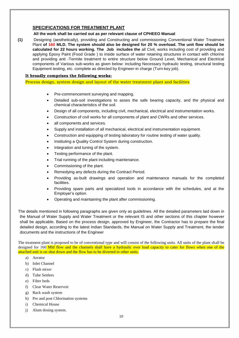
10
SPECIFICATIONS FOR TREATMENT PLANT
All the work shall be carried out as per relevant clause of CPHEEO Manual
(1) Designing (aesthetically), providing and Constructing and commissioning Conventional Water Treatment
Plant of 160 MLD. The system should also be designed for 20 % overload. The unit flow should be
calculated for 22 hours working. The Job includes the all Civil, works including cost of providing and
applying Epoxy Paint (Food Grade ) to inside surface of water retaining structures in contact with chlorine
and providing anti -Termite treatment to entire structure below Ground Level, Mechanical and Electrical
components of Various sub-works as given below: including Necessary hydraulic testing, structural testing
Equipment testing, etc. complete as directed by Engineer-in charge (Turn-key job).
It broadly comprises the following works:
Process design, system design and layout of the water treatment plant and facilities
Pre-commencement surveying and mapping.
Detailed sub-soil investigations to asses the safe bearing capacity, and the physical and chemical characteristics of the soil.
Design of all components, including civil, mechanical, electrical and instrumentation works.
Construction of civil works for all components of plant and CWRs and other services.
all components and services.
Supply and installation of all mechanical, electrical and instrumentation equipment.
Construction and equipping of testing laboratory for routine testing of water quality.
Instituting a Quality Control System during construction.
Integration and tuning of the system.
Testing performance of the plant.
Trial running of the plant including maintenance.
Commissioning of the plant.
Remedying any defects during the Contract Period.
Providing as-built drawings and operation and maintenance manuals for the completed facilities.
Providing spare parts and specialized tools in accordance with the schedules, and at the Employer’s option.
Operating and maintaining the plant after commissioning.
The details mentioned in following paragraphs are given only as guidelines. All the detailed parameters laid down in
the Manual of Water Supply and Water Treatment or the relevant IS and other sections of this chapter however
shall be applicable. Based on the process design, approved by Engineer, the Contractor has to prepare the final
detailed design, according to the latest Indian Standards, the Manual on Water Supply and Treatment, the tender
documents and the instructions of the Engineer
The treatment plant is proposed to be of conventional type and will consist of the following units. All units of the plant shall be
designed for 160 Mld flow and the channels shall have a hydraulic over load capacity to cater for flows when one of the
attached unit is on shut down and the flow has to be diverted to other units.
a) Aerator
b) Inlet Channel
c) Flash mixer
d) Tube Settlers
e) Filter beds
f) Clear Water Reservoir
g) Back wash system
h) Pre and post Chlorination systems
i) Chemical House
j) Alum dosing system.

11
k) Plant-drainage arrangement / Sludge tanks and recirculation System
l) Laboratory
m) Ancillary units
1) Aeration Fountain
Plan area not less than 0.625 square meter per MLD
2) Ventury Flume
With necessary devices, consisting of simple mechanical indicator. ( Pedestal type gauge)
3) Flash Mixer
Rapid mixing device, detention time30 to 60 seconds to give velocity gradient 300 to 400 sec-1 vane mixer type
confirming to I.S. 7090 of 1985.
One each Flash Mixer shall be provided for each set of two Tube settlers. The flash mixer shall be equipped with an impeller
type high speed mixer. The driving motor of suitable capacity and other accessories shall be totally enclosed but easily
accessible for maintenance. The shaft with the impeller shall be freely suspended from the driving gear mounted on a platform
on top of the chamber. Thrust or guide bearing shall be located above the liquid level. The impeller shall be of stainless steel-
316.
The outlet of the flash mixer shall lead directly to the Tube settler. The pipes shall be flanged CI material. For longer stretches
socket and spigot pipes with rubber ring may be used (Tyton) after approval of the Engineer. The chamber of flash mixer shall
be connected to the drainage system by means of a wall duct and a gate valve.
Detention Period 30 to 60 secs.
Free Board 50 cms
A walkway with hand railing shall be provided around the top of the flash mixer and shall be accessible from the ground level
by a staircase.
Material of construction
Shaft - SS 431
Paddles - MS
Drain Valve - Manually operated
Drive motors to be provided with local push button control also.
Tube Settler
The tubes shall be circular of 1.5mm thick black coloured plastic.
Detention Period 10 min.
4) Rapid Sand Filters and Filter House
Filter designed for filtration rate of 5,000 liters per square metre per hour, minimum 2 beds for plant up to 10 MLD,
for larger plants as specified, filters to be located in filter house with roof slab, pipe gallery and platform minimum
5.5 metre in width with constant rate filtration or declining rate filtration.
a) Filter Sand
Effective size 0.45 to 0.70 mm, uniformity coefficient not more than 1.7, nor less than 1.3,depth of water over sand
0.75 M, free board 50 cm, gravel 0.45 M in depth, sand and gravel confirming to I.S. 849 (i)-77, back wash by air
wash, standard appurtenances
b) Wash Water Tank
Capacity to be specified and suitable to supply water to wash specified number of filter beds at a time 12 minutes
@600 lit/ sqm /min. under a head of 12 m at under drain.

12
c) Wash Water Pumps
Capacity to fill water tank in 1 hour with 100 % standby.
d) Air Blowers
Capable of delivering 600 LMP per square meter of free air, of filter area at 0.4 kg/square cm at the under drains
(100% stand by) for period of 5 min.
7) Chemical House in Two Storey’s
a)Ground floor to accommodate 7 days alum requirement and sundry storage (Minimum 4 m height)
b) First floor to accommodate alum and lime tanks.
chain pulley block etc. (min. 5 m height)
c) Solution tanks
Minimum 3 tanks (one for preparation. second for dosing and third as standby), each tank capable of giving 8 hours
maximum dose without interruption, minimum free board 0.30 M, trays for dissolving, level indicator, mechanical
agitation devices, solution feed and drain lines, solution feed device (constant head device, strength of solution up
to 10% only) conforming to I.S. 9222 part-I/1979.
Pure Water Sump and Pump House
a) Capacity of sump (10000 KL)
b) Pump House
Pump house of required size over the sump or by the side.
9) Store House
Suitable for alum storage of three months and 7 days temporary storage, 7 days TCL requirement in mansoon with
20 % extra capacity for other sundry articles.
10) Vacuum feed type chlorinators - make to be approved by UAD.
a) Confirming to I.S. 10533 - A Part-II 1983.
b) Rate of withdrawal as per design.
c) Chlorinator equipment and container room: to confirm to I.S. 10553 Part - I 1983.
d) 100% Stand bye shall be provided
e) Contractor shall provide sufficient nos of toners/ containers for three months consumption.
11) By pass arrangements - C.I. pipes.
i) By passing all units of T.P.
ii) By passing flash mixer, clariflocculator.
iii) By passing flash mixer, clariflocculator & filter units
12) Disposal of waste from WTP: Safe disposal arrangement to nearby nalla including cost of pipe.
13) For WTP of capacity 30 mld and more additional arrangement for backwash water recycle shall be provided,
including sump, pumping machinery, rising main etc. complete.
Drainage arrangements To decant all units of WTP with CI pipes upto boundary of each unit and further extension
with RCC pipes to nearby nalla.
15) Electrical installation.
Both internal and external including entire plant area.
16) Laboratory equipment.
For the testing of incoming Raw water & outgoing Clear water laboratory of suitable Class as per CPHEEO Manual
shall be provided by the Contractor. The Laboratory equipments & Chemicals to be provided should be of GLAXO/
RANBAXY/ MERCK make. Contractor shall provide proper testing instrumentation for checking the water quality

13
parameters in regard to color, residual chlorine, Conductivity, Turbidity, etc. at various critical locations, i.e, inlet
chamber, Clear water sump and at the outlet pipe.
17) Sanitary blocks.
Carpet area-15 square metre minimum up to 25 Mld and 25 square metre above 25 Mld.
18) Administrative block and internal road.
To accommodate office room. chlorine room, laboratory room, panel board room, blower room
etc. and WBM road to connect all units from main gate of plot.
19) Rates given below are inclusive of uplift pressure if any and dewatering during entire work.
20) Disposal of waste from WTP: Safe disposal arrangement to nearby nalla including cost of pipes.
21) For WTP additional arrangement for backwash water recycle shall be provided, including sump, pumping
machinery, rising main etc. complete.
22) All pipes conduits channel with 20% overloading.
23) These rates are applicable for seismic zones-2,3 and 4.
24) All RCC structures shall be constructed in M-300.
25) All pipes and conduits channel with 20% overloading capacity.

14
TECHNICAL SPECIFICATION
A. PUMPS, MOTORS AND ALLIED EQUIPMENTS
PART1: SPECIFICATION FOR VERTICAL TURBINE PUMPS FOR RAW WATER PUMPING
Design, manufacturer, supply, erection, testing commissioning of turbine pumping sets for pumping clear
water including all electrical, mechanical equipment's accessories and civil works viz., foundation of pump,
motor, cable, pipes, fittings for suction, delivery butterfly valves, reflex valve, specials etc., complete as per
details given in this NIT.
1.0 DETAILED SPECIFICATIONS OF PUMPS SETS :
The pumps shall be vertical turbine wet pit type and non pull out design with multistage bowl assembly
directly coupled with vertical hollow shaft motors.
a. The pumps should be KIRLOSKAR/JYOTI/WORTHINGTON/BEACON WEIR/MATHER & PLATT make
only.
1.1 GENERAL SPECIFICATIONS
The pumps shall be water lubricated complete with bowl assembly, column pipe such floor discharge head,
line shaft, oil tubes, foundation plate/sole plate, basket strainer, motor foot stool and all necessary
accessories. The pump shall be designed so as to have a maximum flow capacity not less than 110% of the
rated flow capacity. The pumps shall also be designed for continuously operation at any point of head
capacity curve between 90% and 110% of pump rated flow, without undue vibration or overheating and
thrust bearing should be antifriction type point head.
(A) BOWLS:
The bowl shall be made of close grained cast iron smoothly finished and free any casting defects. The
bowls shall be capable of withstanding hydrostatic pressure equal to twice the pressure at rates capacity or
1.5 times of the shut off head whichever is greater. The water passage in the bowls shall be smooth and
shall have the Nitril rubber linked bearing with bronze shall to save bearing for the impeller shaft. Neoprene
rubber lined bearing with bronze shall should be provided in the bottom of the bowl assembly also.
(B) IMPELLERS :
Impellers shall be closed type made of zinc free bronze statically and dynamically balanced. Impellers shall
be free from any casting defect and shall be properly machined. All the water passage shall be smooth
finished. The impellers shall be secured to shaft with tapered lock collect or key & split rings.
(C) IMPLLER SHAFT :
The impeller shaft shall be of stainless steel with renewable stainless steel sleeves at bearing portion. The
impeller shaft shall be guided by bearing provided in each bowl. The butting faces of the shaft shall be
machined surer to the axis and the shaft shall be chamfered an the edged. The shaft shall have a surface
finish of 0.75 micron as per IS : 3078/1967.
(D) LINE SHAFT :
The line shaft shall be made of High grade carbon steel. The shafts shall be furnished with interchangeable
suctions having a length of 1.25 M / 2.5 M / 3M. The butting faces of shaft shall be machined square to
shaft axis and the shaft ends shall be chamfered on the edges. To ensure to correct alignment of shafts
they shall be perfectly straight.
The shaft shall not have the surface roughness more than 0.75 microns as per IS: 3073/1967.
The shaft shall have the adequate strength to withstand all the forces at + 10% of the critical speed of shaft.
(E) COLUMN PIPE :
Column pipe shall be manufactured from the heavy class M.S. pipe confirming to relevant India Standard
Specification. The column pipe shall not exceed 3.0 meters. in length & made of 6 mm thick sheet the dia.
of bolts to be used in flange joints should not be less than 20mm.
(F) LINE SHAFT BEARING :
Line shaft bearings shall be designed to be lubricated by forced water. line shaft bearing shall be cut less
Nitrile rubber lined bearing with bronze shell.
(G) LUBRICATION :
The pumps are water lubricated.
(H) DISCHARGE HEAD :
The discharge head shall be of standard construction cast iron as per IS:210 Gr. FG 200 and sufficiently
strong to support the weight of the pump. It shall befitted with a tube tension plate for tighten up. The shaft
tubes for the purpose of aligning the shafts.

15
(I) STUFFING BOX :
A packing gland shall be provided at the top of stuffing box. Shaft sleeves shall be provided on the top
shaft. The stuffing box shall be of sufficient depth to permit adequate packing. The space between the
pump motor main coupling and the stuffing box shall be sufficient to permit removal of packing gland and
insertion of new packing without dismantling the pump.
(J) MOTOR STOOL :
The motor stool shall be of fabricated mild steel shall be designed to take care of all static and dynamic
loads on it.
(K) PRESSURE INDICATION DEVICES :
Each pump shall be provided with pressure gauge of best quality makes to give indications of delivery
pressure. The pressure gauges shall be of Borden type, dial size 150mm.
(L) LABORATORY TEST :
Laboratory pump test shall be carried out as per IS: 9137 / for each pump to assess the pump discharge
V/s head, horse power and efficiency figures. The pump shall be subjected to a test pressure of 1.5 times of
the shut of pressure or twice the working (rated) pressure which ever higher.
(O) FIELD TEST :
The field test shall be carried out as per IS : 1710 and 5126.
The successful BIDDER will ensure the Engineer-in-charge of work or any other Senior Engineer nominated
by the CHIEF MUNICIPAL OFFICER, NAGAR PARISHAD KOLARAS will inspect and witness tests
conducted on the pumps and motors at manufacturer's place with respect to their characteristic and
performance as specified by the department.
1.2 GUARANTEED PERFORMANCE & TECHNICAL PARTICULARS :
The contractor shall submit the details of guaranteed performance & technical particulars as desired in the
Performa enclosed vide schedule's with the TENDER along with the preliminary out line drawing indicating
principal dimensions & weight of pumping equipments and cross section drawing indicating the assembly of
pumps & manor parts thereof with materials of constructions and special features. Complete descriptive and
illustrated literature on the equipment and accessories offered.
1.3 SPECIAL NOTES FOR BIDDER :
1.3.1 Pump should be capable of throttling. The throttle point discharge should be quoted. The extent to which
pump can be throttle and the corresponding discharge to be mentioned.
1.3.2 Duty point discharge should be specifically mentioned along with the head at which the same will be
attained. Efficiency at different operating heads and discharge should be mentioned.
1.3.3 The accessories like surface, discharge head/underground discharge head with elbow, prelub tank with
fittings, motor stand with NRR and thrust bearing housing, column assembly bowl, assembly, basket
strainer, as per specifications shall be quoted, individually. The drawing to the scale showing the proposed
arrangements for the pumps and the positions of various parts with detail drawing must accompany the
TENDERs along with detailed specification, make, guarantee period etc.
1.3.4 Head capacity curve shall be rising type and shut off head must be higher than the maximum operating
head for paralleled operations of pumps. Performance covers for each individual pump sets and also for the
four pump sets working in parallel should be given for full load and for throttled conditions also. All pumps to
be of identical in all respect.
2.0 SPECIFICATIONS FOR 415-V INDUCTION MOTORS :
2.1 TYPE :.
The motor shall be vertical hollow shaft squirrel cage type induction motors suitable to operate on 415 V, 3
Phase, 50 Cycle A.C. Supply at 1500 RPM directly coupled with vertical turbine pump. The motor shall
generally confirm to latest revision of IS : 325/1978 and other relevant ISS. Duly fitted with space heater
and RTDs & BTDs. The motor shall be of KIRLOSKAR, JYOTI, BHEL, CROMPTON, NGEF, make only.
2.2 VARIATION IN SUPPLY VOLTAGE :
The motors shall be capable of delivering rated output and rated power factor with following variations :
Voltage : + 10%
Frequency : + 5%
Combined : As per IS 325
2.3 RATED CAPACITY:

16
The minimum conditions rated capacity of motors shall be such that it meets the power requirements of
pumps in the complete range of its operation. It shall also provide on additional power requirement on the
motor. By 5% at the maximum power requirement or by 10% at the duty point of operation whichever is
maximum. The contractor shall ascertain the K.W. requirement and provide the motors of suitable capacity.
2.4 ACCELERATION CHARACTERISTICS:
The acceleration characteristics of motor shall be matched with the driven equipment so that acceleration is
obtained without over heating of motor.
2.5 METHOD OF STARTING:
The motors shall be designed for star/delta/soft starting at full voltage with starting current not exceeding
four times the rated full load current. The motor shall also be designed for a minimum pull out torque of
200%.
2.6 CONDITION OF START:
Motor when started with the drive imposing its full starting torque under the specified supply voltage
variation shall be capable of withstanding at least one successive starts from hot condition to start from cold
condition without damage to the winding.
2.7 CLASS OF INSULATION:
The motor winding shall be provided with insulation conforming to thermal class "F". The maximum
temperature rise of the winding shall not exceed the limits specified from class "B" insulation. The insulation
can be given tropical and fungicidal treatment for successful operation of motor in hot humid tropical
climate. It shall of thermos setting type and shall remain unaffected by heat. The coils shall be highly
uniform with uniform insulation strength and uniform dielectric losses.
2.8 MOTOR CONSTRUCTION:
The motor construction shall be suitable for easy dismantling and reassemble at site with the help of simple
over head crane. The motor shall be of core pack construction attached to the stator frame to facilitate easy
removal and replacement of the winding for maintenance purpose. The over head for winding at both ends
of the core shall be accessible for usual inspection without resorting to major dismantling.
2.9 MOTOR FRAME:
Motor frames shall be rigid fabricated steel they shall be suitably annealed to eliminate any residual stress
introduced during process of fabrication and machining.
2.10 STARTOR LAMINATIONS:
Stator laminations shall be made from suitable grade sheet steel varnished on inner side and shall be
adequately designed to overheating during starting and running conditions stipulated above.
2.11 ROTOR SHORT CIRCUITING RINGS:
Rotor short circuiting and rings shall be such that it is free to move with expansion of bars without distortion.
The connections of the bars to the end rings shall be made by bracing.
2.12 LOCKING ROTOR WITH STAND TIME:
Locked rotor with stand time under hot conditions at 110% voltage shall be more than starting time at
minimum permissible voltage by at least two seconds.
2.13 TYPE OF ENCLOSURE & DEGREE OF PROTECTION:
The degree of protection provided by the enclosures of motor shall conform to IS: 4691. the enclosure for
the motors shall be screen protected Drip Proof (SPDP) IP 23.
2.14 SHAFT INSULATION:
Suitable insulation shall be provided on shaft/bearing house to prevent shaft current. The insulation
provided shall be such that it shall retain its dielectrically properties even after its handled for number of
times during dismantling and reassemble.
2.15 BEARING ASSEMBLY:
Bearing assembly shall be such that it prevents dust and water from getting to the bearing. Further, bearing
lubricant shall not find access to the motor winding. The bearing assembly shall be provided with proper
lubricating nipples.
2.16 EARTHING:
The motor body shall have two separate earthing terminals for earthing in compliance with I.E. Rules.
2.17 DIMENSIONS OF MOTORS:
Motors shall be properly dimensioned to have greater stability and low vibration limit.

17
2.18 TESTING
All the motors shall be routine tested at manufacturers workshop and test certificate shall be provided with
motors.
(Bidder can suggest other options of pumps in the light of less Electrical expenditure and better efficiency without compromising on head and discharge. The change shall have to be approved by the Competent authority. However no separate cost shall be payable for the same.)

18
PART - 1: HORIZONTAL SPLIT CASING CENTRIFUGAL PUMPS FOR CLEAR WATER PUMPING
1.1 GENERAL DESIGN CONDITIONS
The pumps shall be high head single stage horizontally split casing type to facilitate easy inspection & maintenance. The pumps shall be designed to operate satisfactorily while handling a minimum suction lift from all causes nits of pump sets of combined capacity of 160 MLD against approximate total Head of 100 meters for pumping clear water from WTP.
The pump shall be horizontally split with the suction and delivery branches cast INLINE on the bottom half of the casing. The top half should be constructed to allow easy dismantling. There by providing the facility of inspection and repair to the equipment without any difficulty.
The rotating elements of pumps will be dynamically balanced and over stressing should not occur due to sudden failure of power, Reverse rotation should not damage the pumps.
The pumps shall be so designed as to have a maximum flow capacity of not less than 110% of the rated flow capacity.
The pumps shall be designed for continuous operation at any point of head capacity curve between 50% & 110% of pump rates flow without under vibration or overheating.
The pumps shall be so designed as to have a stable non overloading characteristics, capacity head curve shall be continuously from shut-off point to operating point and shall be suitable for parallel operation of pumps without any haunting possibility. The shut-off head should not exceed 120% of duty point head.
The impeller adjustment shall be designed in such a way that impellers run free in any installed condition.
1.2 GENERAL SPECIFICATION
The pump shall be complete with suction pipe, foundation plate/sole plate and all other necessary accessories.
The pumps should generally comply with the requirement of following standard.
1. IS 1520-1972 : Horizontal Centrifugal Pumps for clear, cold and fresh water.
2. IS 5120-1968 : Technical requirement of Rotor Dynamic special purpose pumps.
PUMP MAKE KIRLOSKAR, JYOTI, WORTHINGTON, BEACON AND MATHER & PLATT EQUIVALENT.
1.3 PUMP CASING
The casing should be made of closed grain Cast Iron smoothly finished and smooth surface finish inside free from any casting defects capable of withstanding twice the hydrostatic pressure at rated capacity or 1.5 time the shut off head. Whichever is greater. The water passage shall be completely smooth.
1.4 IMPELLERS
The pump impellers shall be of double suction type and of non-ferrous materials, preferably zinc free phosphorus, bronze,(LTBR IS318 –LTB2 ) designed to inherently provide dynamic-static axial balance. Design of impeller should be such as to prevent cavitations during the working condition specified. The impeller shall be statically and dynamically balanced depending on design considerations to minimum vibration at the pump bearings, thereby prolonging their working life.
1.5 PUMP SHAFT
The pump shaft shall be manufactured from high tensile carbon steel and provided with renewable zinc free bronze sleeves to protect the spindle from the water being pumped.
1.6 INTERNAL PARTS
The pump internal shall be constructed of bronze materials of suitable composition so as to provide compatibility with regard to rubbing surface. Hardness of wearing surface shall be so adjusted as to provide maximum economy in terms of replacement of wearing component i.e. casing neck rings shall be more soft than the impeller neck.
Facilities for gland drainage shall be provided and gland lubrication shall suitably arranged by means of providing connection from the discharge volutes.
1.7 PUMP BEARING
The pump is to be provided with suitably white metal lined split bush bearing and a deep grove ball thrust bearing to take up residual axial balance. These bearing should be oil lubricated.
1.8 PUMP COUPLING
This shall be of flexible pin type equipped with a suitable coupling guard.
1.9 SOLE PLATE
Each pump shall be provided with a heavy structural steel sole plate. Sole plate shall be provided and grouted with foundation. The sole plates shall be designed to permit removal of entire pump without disturbing sole plate.
1.10 PRESSURE INDICATION DEVICE
Each pump shall be provided with pressure gauges of good quality make to give indications of delivery pressure & vacuum pressure separately. The pressure gauges should be designed in such a way that the readings shall not be
19
affected due to mechanical vibrations. The connections sizes shall be 12mm and diameter size 150m. In addition to above each pump shall be fitted with electronic pressure transducer with electronic digital display type indicator in control panel to indicate the delivery vacuum pressure of the pumps.
1.11 BOLTS, NUTS & WASHERS
All bolts, nuts and washers shall be of superior quality conforming to relevant Indian Standard Specification.
1.12 MATERIAL OF CONSTRUCTION
MATERIAL OF CONSTRUCTION OF PUMP SHALL BE SUCH AS TO RESIST EROSION & CORROSION. MATERIALS OF CONSTRUCTION OF VARIOUS COMPONENTS SHALL BE AS UNDER
Pump casing : Cast Iron
Impellers : Zinc free Bronze conforming to relevant IS.
Pump shaft : High Tensile Carbon Steel with renewable Zinc free Bronze sleeves conforming to relevant IS.
Pump Internal : Bronze materials of suitable composition as per relevant IS.
Sole Plate : Fabricated as per IS 226.
Nuts, Bolts & Washers : High Tensile Mild Steel conforming to relevant I.S.
1.13 INSPECTION & TESTING
All the inspection, examination and testing shall be carried out in accordance with relevant In diameter Standard Specification.
1. LABORATORY TEST
Laboratory pump test shall be carried out as per IS: 5120-1968 each pump to assess the pump discharge Vs head, horse power and efficiency figure. The pump casing shall be subjected to a pressure test of 1.5 times the working pressure at duty point.
2. FIELD TEST
The field test shall be carried out as per IS: 1520-1972 & IS: 5120-1968. These test May be witnessed by the Engineer-in-charge or his authorized representative if they desire. The tolerance as specified in relevant IS code of practice shall not be application on the efficiency & KW output. The contractor shall have to demonstrate the quoted efficiency of pump during testing.
1.14 GUARANTEES PERFORMANCE & TECHNICAL PARTICULARS
The contractor shall submit the details of guaranteed performance and technical particulars as desired in the performance enclosed vide schedule 'B' along with the TENDER & the preliminary out line drawing indicating principal dimension and weight of pumping equipment and cross-section, drawing indicating the assembly of pumps & major parts thereof with materials of construction and special features, complete descriptive and illustrated literature on the equipment and accessories offered.

20
PART - II
SPECIFICATION FOR 415 V INDUCTION MOTORS
2.1 TYPE
The motor shall be horizontal SOLID shaft squirrel cage type for clear water pumps suitable to operate on 415 V, 3 phase, 50 Hz. AC supply (with allowable variation of 10%) directly coupled with pumps. The rotations of clear water pumps shall be 1500 RPM. The motor rating generally conform to latest revision of IS 325-1971 and other relevant I.S.S.
2.2 VARIATION IN SUPPLY VOLTAGE
The motors shall be capable of deliver integrated output and rated power factor with following variations:
VOLTAGE : +10%
FREQUENCY : +5%
COMBINED : +10%
PHASE IN BALANCE : +5%
2.3 RATES CAPACITY
The minimum continuous rated capacity of motors shall be such that it meets the power requirements of pumps in the complete range of its operations. It shall also provide additional power requirement in the motor by 5% at the maximum power requirement or by 10% at the duty point of operation whichever is maximum. The contractor shall ascertain the KW requirement and provide the motors of suitable capacity.
2.4 ACCELARATION CHARACTERISTICS
The accelerating characteristics of motor shall be matched with the driven equipment so that acceleration is obtained without over heating of motors.
2.5 METHOD OF STARTING
The motors shall be designed for star/delta/soft/starting at full voltage with starting current not exceeding 2 times the rated full load current. The motor shall also be designed for a minimum pull out torque of 200%.
2.6 NUMBER OF START
Motors when started with the drive imposing its full starting torque under the specified supply voltage variation shall be capable of withstanding at least two successive starts from hot condition and one start from cold condition without damage to the winding.
2.7 CLASS OF INSULATION
The motor winding shall be provided with insulation conforming to thermal class F. The maximum temperature rise of the winding shall not exceed the limits specified for class 'B' insulation. The insulation shall be given tropical and fungicidal treatment for successful operation of motor in hot, humid tropical climate. It shall be of thermo-setting type and shall remain unaffected by heat. The coils shall be highly uniform with uniform insulation strength and uniform dielectric lose. The dielectric losses shall be low and the star delta measurement should be not exceed 1% at 440V.
MAKE OF MOTOR CROMPTON, KEC, ABB AND SEIMENS ONLY.
2.8 MOTOR CONSTRUCTION
The motor construction shall be suitable for easy dismantling and reassembly at site with the help of simple over head crane. The motor shall be of core pack construction attached to the stator frame to facilitate easy removal and replacement of the winding for maintenance purpose. The over head for winding at both ends of the core shall be accessible for usual inspection without resorting to major dismantling.
2.9 MOTOR FRAME
Motor frame shall be of rigid casted steel. They shall be suitably annealed to eliminate up any residual stresses introduced during process of fabrication and machining.
2.10 STATOR LAMINATION
Stator laminations shall be made of suitable grade sheet varnished on either side and shall be adequately designed to avoid over heating during the starting and running conditions stipulated above.
2.11 ROTOR
Rotor should be desisted dynamically balanced and having carbon steel shaft hydraulically fitted.
2.12 LOCKED ROTOR WITH STAND TIME
Locked rotor with stand time under hot conditions at 110% voltage shall be more than starting time at minimum permissible voltage by at least two seconds.
2.13 TYPE OF ENCLOSURE & DEGREE OF PROTECTIONS
The degree of protection provided by the enclosures of motor shall conform to IS : 4691. The enclosure for the motors shall be closed air circuit air cooled (CMMMSPY) type, having of protection I.P. 55.
2.14 SHAFT INSULATION

21
Suitable insulation shall be provided on shaft bearing housing to prevent shaft current. The insulation provided shall be such that it shall retain its dialectical properties even after its handling for number of times during dismantling and reassembly.
2.15 BEARING ASSEMBLY
Bearing assembly shall be such that it prevents dust and water from getting into the bearing. Further, bearing lubricant shall not find access to the motor winding. The bearing assembly shall be provided with proper lubricating nipples.
2.16 EARTHING
The motor body shall have two separate earthing terminals for earthing in compliance with I.E. RULES.
2.17 TERMINAL BOXES
Separate terminal boxes shall be provided for main-Terminals of the motors and for R.T.D. and for space heaters. The terminals box for main terminals of motor shall be segregated type suitable for 3 core. 440 V. Aluminum conductor PVC insulated armored cables. The terminal boxes shall be spacious, dust & house proof designed and properly insulated. Adequate clearance should be given between live motor terminals and covers.
2.18 TEMPERATURE DETECTORS
Motors shall be provided with embedded temperature detectors, two for each phase winding at the location where the high temperatures May be expected in the stator winding. The temperature detectors shall also be provided in bearing assembly for monitoring the bearing temperature. The temperature detectors shall be connected with digital temperature scanners with alarm and trip points in the control panel.
2.19 ANTI - CONDENSATION HEATERS
Motors shall be have space heaters suitable for 240 V. single phase 50 Hz. A.C. supply, space heaters shall have adequate capacity to maintain motor internal temperature above due point to prevent moisture condensation on insulation during shut down periods.
2.20 DIMENSIONS OF MOTORS
Motors shall be properly dimensioned to have greater stability and low vibration limits. Mounting dimensions should confirm to IS : 2254.
2.21 COUPLING TO PUMPS
The motors shall be coupled to the pumps by means of polished steel shaft and flexible coupling. The size of line shaft and flexible coupling shall be calculated on the basis of maximum combined shear stress as per the relevant IS and shall not exceed 30% of the elastic limit in tension or 10% of ultimate tensile stress, shaft shall be designed taking into consideration that critical speed of the shaft which shall be higher than the operating or runaway speed.
2.22 DETAILS OF MOTORS TO BE FURNISHED
The TENDERs shall furnish along with their offer, the details of efficiency, total losses and power at different loads etc. as required in the form of guaranteed performance and technical particulars of motors in schedule 'B'.
2.23 TESTING
All the motors shall be routine an type tested at the supplier's workshop in the presence of Engineer-in-charge of work or his authorized representative or a third party inspection directed by Nagar approve the design.

22
PART-III CABLING AND MOTOR CONTROL PANNEL
3.1 CABLE CLEAR WATER PUMP HOUSE
In case of clear water pump house the soft starter panel of each motor of clear water centrifugal pump shall be
connected in L.T. panel in the pump house, through 300sqmm 3-1/2 core armored cable. Thus in all 2 Nos. of
300sqmm 3-1/2 core armored cable shall be laid in suitable duct and as per I.E.RULE. And a loop of about 1m
should be given in each cable.
3.2 REACTOR TYPE MOTOR SOFT STARTER [MOTOR CONTROL PANEL]
TECHNICAL SPECIFICATIONS:
TYPE OF SOFT STARTER NEUTRAL/LINE REACTOR SOFT STARTER
PRINCIPAL SRSS [SERIES REACTOR SOFT STARTER]
APPLICABLE STANDARD IS 3914 [MOTOR STARTER STANDARD
GUIDELINE]
REACTOR AIR CORE TYPE 100% COPPER WINDING
REACTOR CONNECTION REACTOR TO BE IN SERIES ON LINE OF
MOTORS
STARTING CURRENT LIMIT 2-3 TIMES OF FLSC IN STEPS [DEPENDING
UPON LOAD TORQUE REQUIREMENT
SETTABLE AT SITE]
HARMONIC REACTORS USED IN SOFT STARTERS
CIRCUITS OF AIR CORE SHOULD NOT
DEVELOP HARMONIES IN THE CIRCUITS
DUTY CYCLE 6 NO EQUAL SPACED STARTS/PER HOUR
METHOD OF COOLING AIR COOLED
SPECIFICATIONS FOR OTHER ITEMS SHOULD BE EQUIPPED WITH REQUIRED
SWITCH GEAR PROTECTIONS AND INDICATIONS
3.3 PUMP WELL WATER LEVEL INDICATOR
One No. electrical water level indicator with alarming system shall be provided for the pump well near which
the pump house of clear water has been constructed.
3.4 CIVIL WORK
1. Construction of covered cable trenches / tray from L.T. panel to panel board in pump house. The cable
trenches should be covered with sand and type should be broken type connected to bridge with bolts etc.
by suitable civil work and shall be covered with chequered plates of minimum thickness 7mm.
2. Construction of all other civil works required for erection of pump and motor with all foundation bolts,
washers including all work pertaining to it.
PART - IV - BUTTER - FLY VALVE
4.1 GENERAL REQUIREMENT
Each pump shall be provided with a butterfly valve in the delivery pipe, and in addition one no common butter fly
valve shall be also required in manifolds of each pump house. The butterfly valve shall be flanged, water works
pattern eccentrically pivoted.
The valve shall have head stock, extension rod & wheel for operation and gearing system if the size is 300mm
diameter or above. The valve shall generally confirm to relevant I.S.: 51450.
4.2 CONSTRUCTION
Butter fly valve having diameter equal to the diameter of delivery line suitable for individual flange bolting of flanges
of pipe, with the disc to form a section cut through a sphere, working in conjunction with a cone shaped seating in
body and synthetic rubber seal ring fitted to the disc with the help of a retaining ring & stainless steel screws, shall
be provided, confirming to relevant I.S. STANDARDS. The disc shaft bearing shall be offset along the pipe axis
from the place of the seating so as to get an unbroken position in full closed position.
4.3 MATERIALS OF CONSTRUCTION
1. Body : Close grained homogenous cast steel construction tested to 40 kg/cm2
2. Disc : Same as body tested to 20 kg/cm2
3. End housing and : Cast steel to grade 20 to 25 IS 210 or Cast Iron.
cover gear box

23
housing for manual
operation
4. Bearing : P.T.F.E. (Glass filled or carbon filled) having friction coefficient 0.04 (Note: Water
itself acts as a lubricant for PTFE bearings).
5. Stub Shaft : 18/8 quality stainless steel AIST 304/ASTMA351 Gr. CF.
6. Rubber Seal Ring: For standard water works valve precision moulded nitrite rubber ring (shore hardness 55
to 65).
7. Hardware used : Stainless steel.
Inside
8. Retaining Ring : S.G. Iron or Cast Steel Nickel plated.
9. Inside paint : Black bit mastic.
4.4 TESTING
The valves shall be subjected to closed ends tests as per relevant IS standard. Test certificate in triplicate shall be
furnished. If necessary, test shall be witnessed by the Engineer's representative.
Working Pressure : 20 kg/sq.cm.
Test Pressure Body : 40 kg/sq.cm
Seating : 20 kg/sq.cm.
Gear Box Outside : 1 kg/sq.cm.
PART - V - NON RETURN VALVE
5.1 GENERAL
The non-return valves shall be single door type, free acting quick opening, giving rapid non-clam closure & with low
head loss characteristics when in open position. The valves shall be provided with by passes and isolating valves
conforming to relevant Indian Standard.
Specification of the valves shall generally conform to IS: 5321 (Part-II)
5.2 MATERIALS OF CONSTRUCTION
Body, Cover, Door and Hinges : Cast steel construction
Hinge pins, Door pins & Door : 12% Chromium steel conforming to IS:1570
Suspension pins
Bearing Bushes : Leaded Gun Metal Gr. 2, Conforming to
IS: 318
Body rings and door faces : Leaded Gun Metal Gr.2, conforming to
IS: 318
5.3 TESTING
The valves shall be subjected to closed ends tests as per relevant IS standard. Test certificate in triplicate shall be
furnished. If necessary, test shall be witnessed by the Engineer's representative.
WORKING PRESSURE :20 KG/SQ.CM.
TEST PRESSURE BODY :40 KG/SQ.CM.
SEATING :20 KG/SQ.CM.

24
PART - VI DELIVERY PIPES
6.1 GENERAL
The scope of the work is providing, laying & jointing of all delivery pipes, specials valves of all the pump and
their connection to the common manifold as shown in drawing inclusive of the jointing of the manifolds to
the respective conveyance mains fixing with one main butterfly valve.
1. The contractor shall design and fabricate the common manifold which would be made out of MS 6mm thick
plates conforming to IS: 226 in such a way that it gives minimum frictional loss of head to the flow of water
and also avoid cavitations or vortices in the manifold. The manifolds should be in line and coated with
suitable material to protect it from corrosion in case of clear water ultimate carrying capacity shall be 3.64
MLD.
2. The contractor shall provide an expansion joint of his own design duly approved by the Engineer-in-charge.
3. Flanged joints shall be adopted for valves and butt welding joints or flanged joints in jointing of delivery pipe
with dismantling joints.
4. Concrete saddles for valves and thrust blocks shall be provided by the contractor as per the design and
drawings to be furnished by the contractor and subsequently approved by Engineer-in-charge.
6.2 MATERIAL OF CONSTRUCTION
All the pipes of works shall be fabricated out of steel plates conforming to IS:226-1962. The fabrication of
pipes shall generally conform to IS: 3589-1966.
6.3 TESTING
The pipes and common manifold shall be hydraulically tested to a pressure of 2 times the working pressure.
Test certificate to that effect shall be furnished by the contractor.
The Engineer-in-charge witness the above test if so desired, the contractor shall arrange for such test in
presence of Engineer-in-charge.
PART - VII RATING AND NAME PLATES
7.1 RATING PLATE
Each main and auxiliary item of plate shall have permanently attached to it a rating plates in a conspicuous
position. This shall be a non-corrodible material preferably chromium plates steel. The inscription shall be
engraved in black on the plate.
7.2 NAME PLATE
1. Each item of plant shall be provided with a name plate or label designating the service of the particular
equipment. The shape and size of the plate and inscription shall be approved by the Engineer-in-charge.
2. Such name plate shall be non-corrodible material preferably chromium plated steel having engraved black
lettering.
3. In case of indoor equipment like circuit breakers, starters etc. the plate shall be of transparent plastic
material with black lettering engraved on the back.
4. The name plate shall be screwed to the body of the equipment.
DETAILED TECHNICAL SPECIFICATION FOR 33 KV ELECTRIC SUB STATION (1 no. at WTP)
1. LOCATION OF WORK:-
Providing, supplying, erection and commissioning of Transformer of suitable rating to be installed in an
electric sub-station of 33 KV at WTP
2. SCOPE OF WORK
The Scope of works includes design, supply erection construction commissioning and testing 33 KV ,
electric substation (as per I.E. rules and specification) which mainly includes supply of transformer, outdoor,
substation structure, cables, other electrical equipment, accessories, and other allied required civil work etc.
complete. inclusive of Provision of HT line upto to Transformer.
The details specifications of the proposed work are given below. However specifications laid down in
relevant in diameter standards shall be strictly followed.
2.1 SUB STATION STRUCTURE AND ASESSORIES. :-
33/3.3KV outdoor substation comprising of 1 pole substation structure made of Double M.S. Girders &
channels of adequate section (not less than ISHC 200x10 and ISMB 100x50) and length, with provision, of

25
33 KV lightening arrester, A.B. switch, D.I. set, disc and post insulators with hardware substation premises
as per I.e. rules. Structure shall be complete with necessary painting of primary red oxide and finished with
two coat of aluminum paint.
2.2 TRANSFORMER
Minimum Two number transformer of suitable rating 3 phase, double, wound Dy 11, ONAN cooled outdoor
distribution transformer with off load top changer as per IS 2026 (with all standard fitting and bi directional
rollers and accessories as per I.E. rules) and as per other detailed specification. The transformer shall be
fixed on suitable plinth as per I.E. rules.
2.3 EARTHING SYSTEM:-
Double earthing of entire electrical system connected to earthing plates buried in ground and surrounded in
charcoal and salt up to adequate depth. The contractor shall have to carry out earth continuity tests earth
resistance measurement and all other required test in the presence o the Engineer-in-charge, which are
necessary to prove that complete job. If earthing system is
Already in working conditions then rectifications if required is to be done only
2.4 CIVIL WORK:
All related civil works such as construction of transformer plinth, foundation of substation structure, partition
wall between transformer, earth pits, cable trenches/cable trays, cable markers, foundation of Fencing pole
structure, providing and spreading 40mm B.T. metal as per I.E. Rules complete job.
2.5 FENCING FOR SUBSTATION YARD.
Industrial yard fencing arrangement using 65 mm x 6mm angle iron post complete as per I.E. rules
complete job if require at site
2.6 LIGHTING:-
Sub station yard lighting provision in panel.
2.7 SUPPLY OF SAFETY DEVICES:-
Supply of safety devices like rubber mating, hand gloves, first Aid box, danger boards, first Aid, charts, 0.5
Kg. Capacity Co2 type fire extinguishers and sand buckets etc. complete required as per specification and
I.E. rules One set.
2.8 OPERATION OF SUBSTATION:
The contract includes as operation and maintenance of the contract includes substation after
commissioning and training to departmental staff for 7days complete job.
2.9 ANY WORKS Equipment not specified in particular but considered necessary to complete the work as per
specification and I.E. Rules are also include in this TENDER and scope of works.
2.10 PANEL INSTLATIONS;
Panel is to be installed in substation or at place specified by the department.
3.0 IMPORTANT CONDITIONS:-
3.1 The BIDDER shall submit the brand names & efficiencies at various at various points and design calculation
for each and every equipment so as to assess and decide suitable offer.
3.2 A licensed class A electrical contractor authorized under I.E. Rules shall only carry out the work.
3.3 The Successful BIDDER on award of contract shall have to prepare and submit the detailed drawing of the
work duly approved by the Chief Electrical Inspector and Electrical Adviser, Govt. of M.P. After completion
of work the representative of the Chief Electrical Inspector and Electrical Adviser shall inspect the same.
The inspection the same. The inspection fee shall be borne by the contractor and electrical substation shall
be charged only after approval and permission of the competent authority as per I.E. Rules.
3.4 Supply and inspection of all the equipments shall be as per relevant BIS/ I.S. Specification and latest I.E.
Rules.
3.5 Make, Materials, Technical specification, Circuit diameter grams and connection details of each and every
equipment and its major parts offered should be clearly specified in the TENDER.
3.6 Test certificates guarantee, certificate and operation manual shall be submitted along with the supply of
equipment.
3.7 After commissioning of all the equipment successful trial will have to be given for at least 72 Hours.
3.8 Maintenance and training of department staff:-
After installation, commission and official testing of electric substation and other equipment satisfactorily,
the contractor shall have to run and maintain and electric substation to the complete satisfaction of the

26
Engineer in charge for a period of at least 7 days round the clock through his experienced and competent
staff under supervision of his experienced and qualified engineer.
3.9 Any work equipment not specified in particular but considered necessary to complete the works as per
specification and I.E. Rules are also included in this TENDER.
4. DESIGN DATA:-
4.1 All the equipment shall be designed for operation in tropical humid climate subject to heavy rainfall and
frequent thunderstorms with ambient air temperature of 50 deg. c (max)
4.2 The single line diameter gram of proposed 33 KV substation, main electric panel board bus bar is shown in
the enclosed drawing. The proposed site plan showing the relative location of substation with respect to
pump house is shown in separate drawing, which can be seen in office. The above drawing is enclosed
only for the guidance of the BIDDER.
4.3 The rating and specification of transformers and other electrical equipment shown in the drawing and
specification are indicative only The BIDDER shall checkup the rating of the equipment and satisfy
thoroughly regarding their adequacy.
4.4 All the materials used in this work must be strictly in accordance with the relevant I.S. specification and I.E.
rulers.
4.5.1 On completion of work, the contractor shall submit the completion drawing. Circuit diameter grams and
detailed electrical mechanical drawing of the equipments and the maintenance manuals in form as desired
by the engineer-in-charge.
5. DETAILED TECHNICAL SPECIFICATION:
5.1 TRANSFORMER:-
(a) 33 KV 3 phase, 50 Hz Oil immersed, Natural self cooled type Onan, core type with class "A" insulation,
double wound with off load tape changer outdoor distribution transformer with accessories designed and
manufactured with particular reference to tropical condition conforming to IS 1026: 1981 as per IE rules and
as per detailed specification.
Rating OF SUITABLE RATING
No load voltage ratio (HV/LV 33 KVA/3.3 KV
Winding materials copper
No of phases Three
Vector Dy 11
Connection On (HV/LV) Delta Star
Frequency 50 Hz
Installation Outdoor
Type of cooling Onan
Temperature rise in oil by thermometer 45 Deg. C
In winding of resistance 55 Deg. C
Terminal Arrangement
*(a) Primary Bare
(b) Secondary Weather proof bare bushing
Type of tap changer Off load top changer
Tapes step on HV +5% - 5% in steps of 2.50%
Fitting and accessories shall be provided as per IS 2026: 1981
5. 2 CONSTRUCTION:
CORE
The core shall be of C.R.G.IO. annealed steel materials having low losses and good grain properties, bolted,
together to the frames firmly to prevent vibration and noise,
WINDING:-

27
Winding shall be made out of electrolytic grade copper paper covered wire strips. Generally H.V. winding shall be
cross order of disc type with paper covered conductor and the L.V. winding, shall be cylindrical type disc or helical
type depending upon the voltage currents.
TANK:-
Transformer tank shall be robust construction and shall be fabricated with M.S. plate proper enforcement shall be
provided so as to ensure that no building occurs during service.
FITTING AND ACCESSORIES:-
All the fitting and accessories as mentioned below shall be of the good quality and confirming to Relevant IS
specification.
1. Rating and diameter gram plate.
2. Earthing terminals
3. Lifting lugs
4. Off load tape changing switch
5. Drain cum sampling valve wit plug.
6. Conservator with oil level gauge
7. Thermometer
8,. Air release plug.
9. Silica gel breather.
10. Bucholes Relay.
11. Radiametertor.
PAINTING:-
Thank in side, core clamp and other fitting exposed to the oil shall be painted by heat and oil resistant paint. the
exterior of the transformer and other ferrous fitting shall be first thoroughly cleaned, scraped and ten given two
coats of zinc chromate, red oxide, primer following by two finishing coats of synthetic enamel paints as per shade
No.631, of IS 5/1978.
DRAWING:-
Three copies of GA drawing showing details dimension and position of fitting and accessories shall be
submitted with equipment.
v. Indicating lamps for breaker ON/OFF Spring charge trip circuit healthy.
vi. Alarm Bell for S/C and E/F indication.
vii. Push button for test /reset/acknowledge.
6 PANEL BOARD
The LT AC Switch Board shall be of volts, 3 phase and neutral 50 Hz Distribution board, indoor type, sheet
clad by 1.5mm thick CRC sheet over S channel structure frame, floor mounted free standing type, cubical
pattern, dust & vermin proof having protection group IP 53, and shall comprise of following.
1 Nos. of incoming ACB OF suitable rating make L&T siemens, Alsthan
C&S and Schinder
1Nos. SFU OF suitable rating
- 1Nos. off 144 sq. mm flush tie ampere meter with selector switch.
- 1Nos. set of Indication Lamps for all three phase, On OFF auto Trip .
- 1 Nos. set of CT for protection and metering.
- 1 Nos. of solid state Triple pole on directional IDMTL over load and earth fault relay.
- The bus bar shall be suitable for 3 Phase and applicable amps,. the bus bar shall be with colored insulated
sleeves. The supports shall be suitable spaced to give mechanical rigidity for with standing stress due to
system fault,. The panel compartments shall have adequate space for termination of incoming and
outgoing feeder cables equipped with gland, lugs etc. Panel Board should have a digital display unit
showing line voltage, phase voltage, current and power factor. Control panel should have automatic
capacitor bank.
7 CABLES:-
Power cable of PVC, aluminum armored cable of size 3x400mmx3,5 with require lugs gland. Total to be
considered for lump sum offer is 20 meter. each from transformer to panel.

28
Control cable of PVC, copper cable of size 1 x 2.5 sq.mm x 3 and 6 core with required lugs, glands. Total
length to be considered for lump sum offer is 50mtr, for various connections.
Units rates of cable to be quoted for any addition as required at time of execution.
8 SUB STATION STRUCTURE ADN ACCESSORIES.
8.1 33/0.44 KVA outdoor substation comprising of suitable substation structure and other required substation
material as given below:
8.2 SUB STATION STRUCTURE:-
Sub station structure extension made of 1 Nos. of two pole structure made out Two Nos. of 200xc 100mm
M.S. channels fabricated and welded using 33 x 5 mm. M.S flat to make one pole of substation total
substructure have our poles MS channels shall be not less than 100x 50mm and length as required to
complete the substation structure, clamps, nut bolts and other necessary MS Material as required for
construction of substation structure. These structures shall be made as per detailed drawing enclosed.
8.3 3 KV Lightning arresters:
Station class 1- KA rating, single pole lightning arrester for use of 33 KV solidly ground natural system and
suitable for pedestal mounting complete with bolts and nuts. One SET of three numbers.
8.4 AIR BREAK SWITCHES:-
Air break switches 33 KV 400 amp. Triple pole with earth blades, gang operated, double break isolators
suitable for horizontal mounting, complete with locking arrangement in both On/Off position post type
insulators operating pipe arcing horns, hand operated machismo. The isolators will be complete with fixing
bolts and nuts. all hardware parts shall be hot dip Galvanized.
8.5 DROP OUT FUSES:-
Drop out fuses 33 KV outdoors drop out fuse cut out of expulsion type compete with insulators mounted on
bas channels and suitable for cross arm mounting for a working current up to 400 amps. complete with fuse
holders, fuse elements and operating rod. All hardware pa5rts shall be hot dip galvanized Each set
comprise for 3 Mps single pole drops fuses. The drop out fuse set shall be for control of 500 KVA
Transformer Primary One set.
8.6 Post pin and Disc insulators
33 KV disc insulator complete with hardware.
33 KV pin post complete with GI pin
8.7 ALUMINUM TUBULAR BUSBAR:-
Aluminum tabular bus bar required for internal connection of 33 KV equipment such as transformer Isolator,
DO fuse etc. Jumpers, Terminal connectors connection supports. insulators bolts nuts etc complete
8.8 PAINTING
Structure shall be complete with necessary painting of primary red oxide and finished with two coat of
aluminum paint.
9 SHIFTING OF TRANSFORMER
There is no work of shifting of old transformer.
10 CIVIL WORK
All related civil work such as construction of transformer plinth foundation of substation structure earth pits
cable trenches/ cable trays, cable markers, providing and spreading 40 mm BT metal as per IE rules
complete job.
11 EARTING SYSTEM:-
Double earthing of entire electrical system connected to earthing plates buried in ground and surrounded in
charcoal and salt up to adequate depth, where damaged earth is encountered at a distance of 2 meters
from any permanent structure shall be provided. It shall also included digging of pits earth plates as per
latest IS, watering pipe with funnel of required length and diameter earth strip per without kinks lugs and
clamps, salt and charcoal earth chamber etc as per EI rules the contractor shall have to carry out earth
continuity tests, earth resistance measurement and all other required test in the presence of the Engineer
in charge which in his opinion are necessary to prove that the system is in accordance with design
specification and as per IE rules complete.
11.1 EARTHING MATERIAL
Copper earthing plate of size 3.15 x 600x 600mm 6 nos
Copper earthing strip 50x 5 mm as required
GI earthing plate of size 6.3 x 600x600mm

29
GI earthing strip 50 x 5mm as required for earthing arrangement
CI main hole cover for earthing pits.
GI pipe for earthing pits 50 mm diameter of length 1.5 meter
Funnel and other required earthing materials as per IE rules & IS
12 FENCING FOR 33 KV SUBSTATION YARD
Industrial type fencing arrangement using 65 mm x 6mm angle iron post each of 3 meter height fixed as
required at a spacing of 2 meter with 2 meter high GI chain link wire mesh fencing of minimum opening of
75mm x 75mm 2 meter wide main gate with locking arrangement and etc complete as per IE rules
complete job.
13 LIGHTING
Sub station lighting provision in panel is to be done.
14 SUPPLY OF SPARES
Supply of essential spares like DO fuses HRC fuses indication lamps cable lugs for maintenance one set
15 Supply of essential tools
Supply of essential tools and equipment like DO operating rod earthing rod sets, required for operation of
substation helmet HD one set of each item.
16 SUPPLY OF SAFETY DEVICES:
Supply of safety devices like rubber mating gloves, first Aid box leather apron danger boards, first and
charge 0.5 kg capacity CO2 type fire extinguisher and sand buckets etc complete required as per
specification and IE rules one set.
Note: The quantities given in annexure E&F are approximate. However the contractor shall have to execute the
complete works as per specification and IE rules.
The equipment of following brand shall be required & accepted.
S. No. Equipment Acceptable makes
1. Transformer NGEF, Crompton, Alsthom, Kirloskar, Voltemp btcl,
TESLA
2. 3 KV VCB CROMPTON, ALSTHOM, ABB, JYOTI, SIEMENS,
BHEL, NIEPE-BANGLORE
3. AIR CIRCUIT BREAKER L & T, SIEMENS, ABB, JYOTI, CROMPTON, C & S
4. CTS PTS CROMPTON, ALSTHOM, UNIVERSAL, JYOTI,
C&S
5. 44 KV LIGHTING ARRESTER IGE, OBLUM ALPRO, CROMPTON
6. RELAYS L & T, SIEMENS, ABB, JYOTI, C&S
7. AIR BREAKS SWITCHES SIL, WSL, KIRON TEXTILE
8. POST AND DIS INSULATORS SIL, WSI, KIRON TEXTILE, ATLAS JAIPURIA,
JYOTI
9. ALUMINUM TUBULAER BUSBAR AS PER IE RULE AND AS PER RELATIVE
STANDARD
10. CABLES FINOLEX UNIVERSAL HAVELLS NICCO CCI
11. DROP OUT FUSES SIL, WSI, KRON TEXTILE, ATLAS, JAIPURIA
12. EARTHING MATERIAL AS PER IE RULES AND AS PER RELATIVE
STANDARD D
13. SAFETY DEVICE AS PER IE RULE AND AS PER RELATIVE
STANDARD
14. METERS AE, MECO.

30
The following manufacturers are recommended to be used for the proposed work. The Bidders May substitute
alternative equivalent brand names with prior approval of Engineer in charge.
Item / Component Recommended makes
VT and Centrifugal Pump Kirloskar / Jyoti / Mather+Platt / WPIL/ Aqua / Maxflow
/Darling
Pump motor Kirloskar / Jyoti / Crompton / ABB / Elsthom / Siemens
Sluice Valve / Scour Valve Kirloskar / IVC / VAG / IVI / marck
Non-return / Check Valve Kirloskar / IVC / VAG / IVI / marck / marck
Kinetic Air Valve Kirloskar / IVC / VAG / IVI / marck
Butterfly Valve Fouress / IVC / VAG / L&T (Audco) / marck
Valve Actuator Auma / Rotork / Limitork
Single faced Sluice Gate / Stop-log Kirloskar / JASH / VAG
Flow & Pressure regulating Valve Darling Muesco / VAG / Keystone
Electro-magnetic Flow meters – Battery operated Emerson / Krohne Marshall / Yokogawa / Endress Hauser
Water Hammer Control Sureseal or equivalent
D.I. pipe Specials & Fittings Electrosteel / KISWOK / Jindal / Kejariwal
Electro-fusion & Compression fittings Glynwed / Georg Fisher/Astore/Magnum
Chlorinators Pennwalt (W&T), SIEMENS, Alldos
Chlorine leakage detectors Pennwalt (W&T), Capital Control(US), Alldos
WTP Equipments :
(Bar Screen, Flash mixer, Clariflcculator, Clarifier,
Pressure Sand filter, Activated Carbon filter,
Chemical dosing system etc.
Voltas / Shivpad / Triveni / Hindustan Dorr-Oliver
Power Transformers ABB / Crompton / Emco / Siemens / Alstom
HT Switch Gear Alstom / Jyoti / Crompton / Siemens
Vacuum Circuit Breaker (VCB) Siemens / Schneider M.G. / Jyoti / L & T
Air Circuit Breaker (ACB) Siemens / Schneider M.G. / Jyoti / L & T
Moulded Case Circuit Breaker MCCB Siemens / Schneider M.G. / Jyoti / L & T
Soft starters Siemens / Alstom / Jyoti / ABB / Schneider M.G.
Relay and Contactors Siemens / Alstom / Jyoti / ABB / L&T
Cables Tropodur / Finolex / Asian / Gloster / Incab / Universal /
Polycab / C%S
EOT crane Hitech / Indef / Hiking / Ambika

31
1
FOR INSTRUMENTATION, AUTOMATION AND SCADA SYSTEM :
Programmable Logic Controllers (PLC) Rockwell (Allen Bradly) / Siemens / Honeywell
Panel Enclosures and Consoles Rittal / President / Cutler Hammer
Ultrasonic Type Level Measurement Device Endress+Hauser / Krohne Marshall / Hycontrol UK.
Float & Board Type Level Measuring system Nivo (Toshniwal), Endress + Hauser, Pune Techtrol
Switch fuse Disconnector L & T, FN Type, Siemens, GEPC
Multi-Function Energy Meters Enercon, L & T, SOCOMEC
Capacitor bank Crompton Greaves, Khatau Junker, Malde, L &T
Cable Termination kit Raychem, Denson, M-Seal
Battery HBL NIFE, Exide, Amco
Battery Charger Chaabi Electrical, Masstech
Tacho Meter on line Kana Electric, Proton, Jay Shree Electronics
Pressure switch Indfoss, Switzer,Tag Process Instruments
Flow switch Switzer, General Instrument,Forbes Marshall
Pressure gauge WAREE, WIKA, AN Instruments, Guru, Hitek
Pressure Transmitter Emerson, Foxbro, Druck, Endress – Hauser, ABB,
Honeywell Automation
Engineering cum Operator work Station IBM, Compaq, Dell
Printer EPSON, HP, CANNON, WIPRO
Local Supervisory Station IBM, Compaq, Dell
HMI Software Wincc, Rs View, Monitorpro, Intellution, Indusoft
Alarm Annunciator Minilec, Peacon, ICA, APLAB
Uninterruptible Power Supply HI-Real, Pulse, Tata Libert, APC, APLAB
Instruments & Control Cables Delton, Asian, Servel, TCL, Thermopad
Receiver Indicator/Digital panel meter Masibus, Yokogawa, Lectrotek, NISHKO, SaiTech, MTL
INSTS
Intercom system Betel, Samsung, Tata, Panasonic, Matrix
Conductivity level switch Pune techtrol, Krohne Marshall, E+H
Multifunction power monitor MASIBUS, L&T, ENERCON, SOCOMECH, SECURE, DAE
Temperature Scanner SaiTech, Masibus, Nishko, Lectrotek
Analog Signal Multiplier MASIBUS, Sai Tech, MTL INSTS, NISHKO
Portable vibration measuring equipment Shrenk Every, IRD, STM Instrument, TIME
Portable sound measuring equipment CENTER, MECORD, CYNGET