Obstacle Detection and Navigation Planning for Autonomous ... · Obstacle Detection and Navigation...
8
Obstacle Detection and Navigation Planning for Autonomous Micro Aerial Vehicles Matthias Nieuwenhuisen, David Droeschel, Marius Beul, and Sven Behnke Abstract— Obstacle detection and real-time planning of collision-free trajectories are key for the fully autonomous operation of micro aerial vehicles in restricted environments. In this paper, we propose a complete system with a mul- timodal sensor setup for omnidirectional obstacle perception consisting of a 3D laser scanner, two stereo camera pairs, and ultrasonic distance sensors. Detected obstacles are aggregated in egocentric local multiresolution grid maps. We generate trajectories in a multi-layered approach: from mission planning to global and local trajectory planning, to reactive obstacle avoidance. We evaluate our approach in simulation and with the real autonomous micro aerial vehicle. I. I NTRODUCTION Micro aerial vehicles (MAVs) are enjoying increasing popularity. Due to their low cost and flexibility, they are used for aerial photography, inspection and surveillance missions. In most cases, a human operator pilots the MAV remotely to fulfill a specific task or the MAV is following a predefined path of GPS waypoints in an obstacle-free altitude. Our MAV is shown in Fig. 1. We aim for a fully au- tonomous creation of semantic maps of buildings on demand of a user. Hence, the MAV has to operate at low altitudes in the vicinity of facades and other structures, e.g., trees, street lights, and power cables. This requires more elaborated means of navigation than direct flight between predefined GPS waypoints. We follow a multi-layered approach to navigation: from slower deliberative to fast reactive layers, including mission planning, global and local path planning, fast local obstacle avoidance, and robust motion controllers. Although we aim at mapping the environment during execution, prior knowledge can aid our mission planning—in contrast to fully autonomous exploration of unknown space. We incorporate 3D city models as acquired by land surveying authorities, i.e., a Level-of-Detail 2 (LoD2) model containing footprint, height, and roof-shape of buildings [1] and a digital elevation model (DEM) of the environment. These models do not include smaller structures, which constitute a collision hazard for the MAV. Thus, the initial mission plans need to be adjusted on the fly, whenever more information becomes available during a flight. Nevertheless, buildings are often the largest obstacles and might inhibit local path planners to find a feasible path towards the global goal. Other obstacles, e.g., power poles, vegetation, or building attachments, are likely This work has been supported by grants BE 2556/7 and BE 2556/8 of German Research Foundation (DFG). The authors are with the Autonomous Intelligent Systems Group, Institute for Computer Science VI, University of Bonn, Germany [email protected] Fig. 1: Our MAV is equipped with eight co-axial rotors and a plurality of sensors, including a continuously rotating 3D laser scanner and two stereo camera pairs. to be small enough to be covered by our local obstacle map, built by means of efficient multiresolution scan registration. Hence, a globally consistent path enables a local planner to navigate towards a global goal. MAVs pose a problem for designing sensory systems and perception algorithms due to their size and weight constraints and limited computing power. In order to enable navigation in difficult 3D environments for autonomous MAVs, we developed a small and lightweight continuously rotating 3D laser scanner that measures distances of up to 30 m in almost all directions. It consists of a Hokuyo 2D laser range finder (LRF) which is rotated by a servo actuator to gain a 3D FoV, as shown in Fig. 2. Up to now, such 3D laser scanners are rarely used on MAVs due to their payload limitations. Instead, two-
Transcript of Obstacle Detection and Navigation Planning for Autonomous ... · Obstacle Detection and Navigation...
Obstacle Detection and Navigation Planning for Autonomous MicroAerial Vehicles
Matthias Nieuwenhuisen, David Droeschel, Marius Beul, and Sven Behnke
Abstract— Obstacle detection and real-time planning ofcollision-free trajectories are key for the fully autonomousoperation of micro aerial vehicles in restricted environments.
In this paper, we propose a complete system with a mul-timodal sensor setup for omnidirectional obstacle perceptionconsisting of a 3D laser scanner, two stereo camera pairs, andultrasonic distance sensors. Detected obstacles are aggregatedin egocentric local multiresolution grid maps. We generatetrajectories in a multi-layered approach: from mission planningto global and local trajectory planning, to reactive obstacleavoidance.
We evaluate our approach in simulation and with the realautonomous micro aerial vehicle.
I. INTRODUCTION
Micro aerial vehicles (MAVs) are enjoying increasingpopularity. Due to their low cost and flexibility, they are usedfor aerial photography, inspection and surveillance missions.In most cases, a human operator pilots the MAV remotely tofulfill a specific task or the MAV is following a predefinedpath of GPS waypoints in an obstacle-free altitude.
Our MAV is shown in Fig. 1. We aim for a fully au-tonomous creation of semantic maps of buildings on demandof a user. Hence, the MAV has to operate at low altitudesin the vicinity of facades and other structures, e.g., trees,street lights, and power cables. This requires more elaboratedmeans of navigation than direct flight between predefinedGPS waypoints. We follow a multi-layered approach tonavigation: from slower deliberative to fast reactive layers,including mission planning, global and local path planning,fast local obstacle avoidance, and robust motion controllers.
Although we aim at mapping the environment duringexecution, prior knowledge can aid our mission planning—incontrast to fully autonomous exploration of unknown space.We incorporate 3D city models as acquired by land surveyingauthorities, i.e., a Level-of-Detail 2 (LoD2) model containingfootprint, height, and roof-shape of buildings [1] and a digitalelevation model (DEM) of the environment. These modelsdo not include smaller structures, which constitute a collisionhazard for the MAV. Thus, the initial mission plans need tobe adjusted on the fly, whenever more information becomesavailable during a flight. Nevertheless, buildings are often thelargest obstacles and might inhibit local path planners to finda feasible path towards the global goal. Other obstacles, e.g.,power poles, vegetation, or building attachments, are likely
This work has been supported by grants BE 2556/7 and BE 2556/8 ofGerman Research Foundation (DFG).
The authors are with the Autonomous Intelligent Systems Group,Institute for Computer Science VI, University of Bonn, [email protected]
Fig. 1: Our MAV is equipped with eight co-axial rotors anda plurality of sensors, including a continuously rotating 3Dlaser scanner and two stereo camera pairs.
to be small enough to be covered by our local obstacle map,built by means of efficient multiresolution scan registration.Hence, a globally consistent path enables a local planner tonavigate towards a global goal.
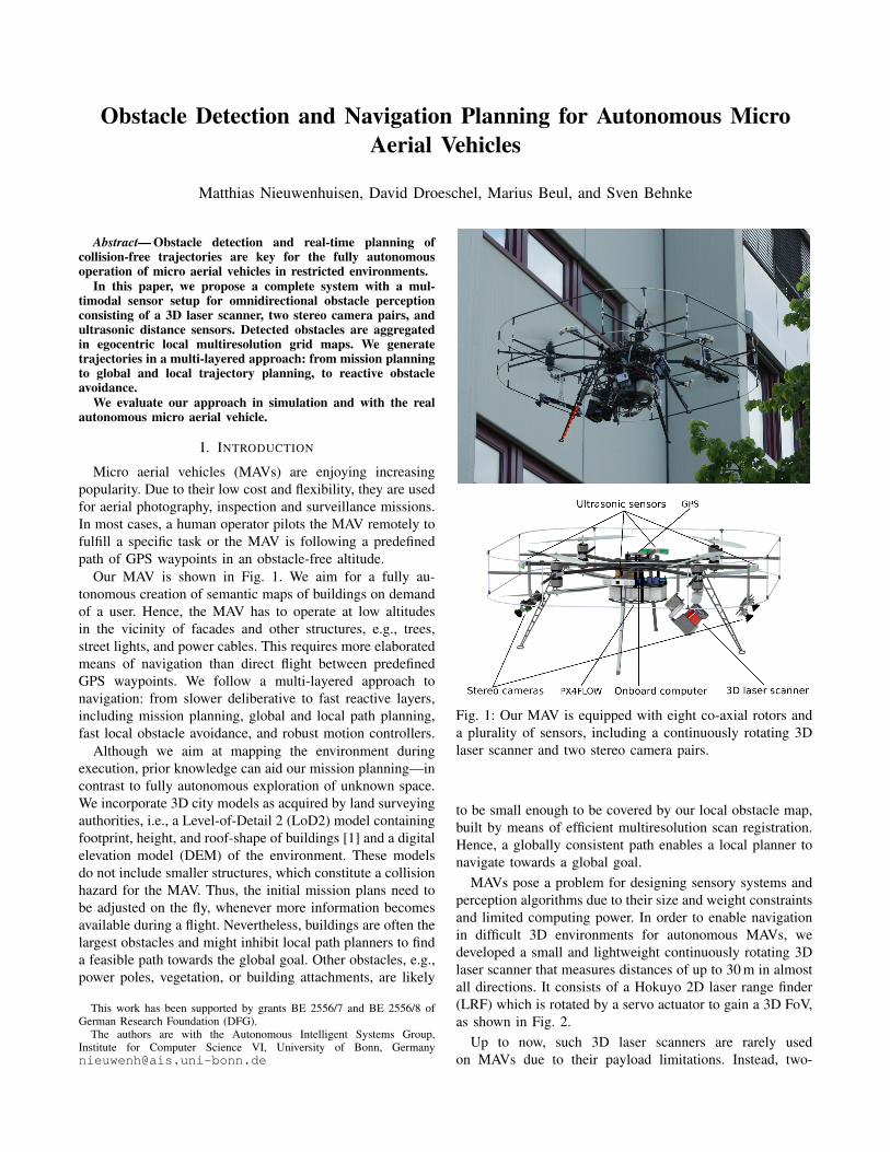
MAVs pose a problem for designing sensory systems andperception algorithms due to their size and weight constraintsand limited computing power. In order to enable navigationin difficult 3D environments for autonomous MAVs, wedeveloped a small and lightweight continuously rotating 3Dlaser scanner that measures distances of up to 30 m in almostall directions. It consists of a Hokuyo 2D laser range finder(LRF) which is rotated by a servo actuator to gain a 3D FoV,as shown in Fig. 2.
Up to now, such 3D laser scanners are rarely usedon MAVs due to their payload limitations. Instead, two-
behnke
Schreibmaschine
In Proceedings of International Conference on Unmanned Aircraft Systems (ICUAS), Orlando, USA, May 2014.
dimensional laser range finders are used [2], [3], [4], [5],which restricts the field-of-view to the two-dimensionalmeasurement plane.
Additionally, our MAV is equipped with two stereo camerapairs, and ultrasonic sensors covering the volume around theMAV up to 30 m range [6]. All these sensors have only localprecision. This is reflected in the local multiresolution prop-erty of our MAV-centric obstacle map. The local navigationplanner operates directly on this representation. We employ3D local multiresolution path planning, extending ideas fromour prior work [7]. This efficient planning technique allowsfor frequent replanning, which makes 3D navigation indynamic, unpredictable environments possible.
After a discussion of related work in the next section,we introduce our MAV in Sec. III. Sec. IV describes ourlocal multiresolution obstacle map. Our hierarchical controlarchitecture from global path planning to low-level control isdetailed in Sec. V. We present evaluation results in Sec. VI.
II. RELATED WORK
The application of MAVs varies especially in the level ofautonomy—ranging from basic hovering and position hold-ing [8] over trajectory tracking and waypoint navigation [9]to fully autonomous navigation [2].
1) Obstacle Perception: Particularly important for fullyautonomous operation is the ability to perceive obstacles andto avoid collisions. Obstacle avoidance is often neglected,e.g., by flying in a sufficient height when autonomouslyflying between waypoints. Most approaches to obstacleavoidance for MAVs are camera-based, due to the limitedpayload [10], [11], [12], [13], [14], [15], [16], [17]. Hence,collision avoidance is restricted to the field of view (FoV) ofthe cameras. Moore et al. [18] use a ring of small cameras toachieve an omnidirectional view in the horizontal plane, butrely on optical flow for speed control, centering, and headingstabilization only.
Other groups use 2D laser range finders (LRF) to local-ize the UAV and to avoid obstacles [2], limiting obstacleavoidance to the measurement plane of the LRF, or combineLRFs and visual obstacle detection [3], [19], [20]. Still, theirperceptual field is limited to the apex angle of the stereo cam-era pair (facing forwards), and the 2D measurement planeof the scanner when flying sideways. They do not perceiveobstacles outside of this region or behind the vehicle.
We allow omnidirectional 4D movements of our MAV,thus we have to take obstacles in all directions into account.Another MAV with a sensor setup that allows omnidirec-tional obstacle perception is described in [21].
2) Navigation Planning: A two-level approach tocollision-free navigation using artificial potential fields onthe lower layer is proposed in [22]. Similar to our work,completeness of the path planner is guaranteed by an allo-centric layer on top of local collision avoidance.
Some reactive collision avoidance methods for MAVsare based on optical flow [23] or a combination of flowand stereo vision [24]. However, solely optical flow-basedsolutions cannot cope well with frontal obstacles and these
Fig. 2: 3D laser scanner. A 2D LRF is continuously rotatedaround the red axis.
methods are not well suited for omnidirectional obstacleavoidance as needed for our scenario.
Recent search-based methods for obstacle-free navigationinclude work of MacAllister et al. [25] and Cover et al. [26].A good survey on approaches to motion planning for MAVsis given in [27]. These methods assume complete knowledgeof the scene geometry—an assumption that we do not makehere.
III. SYSTEM SETUP
Our MAV platform is an octorotor platform with a co-axialarrangement of rotors (see Fig. 1). This yields a compactflying platform that is able to carry a plurality of sensorsand an onboard computer with sufficient computing power(Intel Core i7-3820QM 2.7 GHz) for sensor data processingand navigation planning employing the Robot OperatingSystem (ROS [28]) as middleware. For low-level velocityand attitude control the MAV is equipped with a PIXHAWKflight control unit [29]. To allow for safe omnidirectionaloperation of the MAV in challenging environments our MAVis equipped with a multimodal sensor setup. Our main sensorfor obstacle perception is a continuously rotating 3D laserscanner (Fig. 2). The measurement density of the 3D laserscanner varies and has its maximum in a forward-facingcone. Only a small portion above the MAV’s back is occludedby its core. Two stereo camera pairs (pointing in forwardand backward direction) are used for visual odometry andobstacle perception. Equipped with fish-eye lenses they covera large area around the MAV. Eight ultrasonic sensors aroundthe MAV complete the perception setup. Despite their limitedrange and accuracy, they aid the perception of small obstaclesin the vicinity of the MAV, such as tree branches, overheadpower cables and transmission lines. The fusion of thesesensors facilitate the reliable detection and avoidance ofobstacles. Their fusion is discussed in Sec. IV-C.
For localization and state estimation, we use GPS and anoptical flow camera [30] in addition to the two stereo camerapairs and the 3D laser scanner. The flow camera is pointingvertically to the ground and can—given suitable lightingconditions—measure velocities relative to the ground-planewith more than 100 Hz. We detail our sensor setup and theprocessing pipeline in [6], [31].
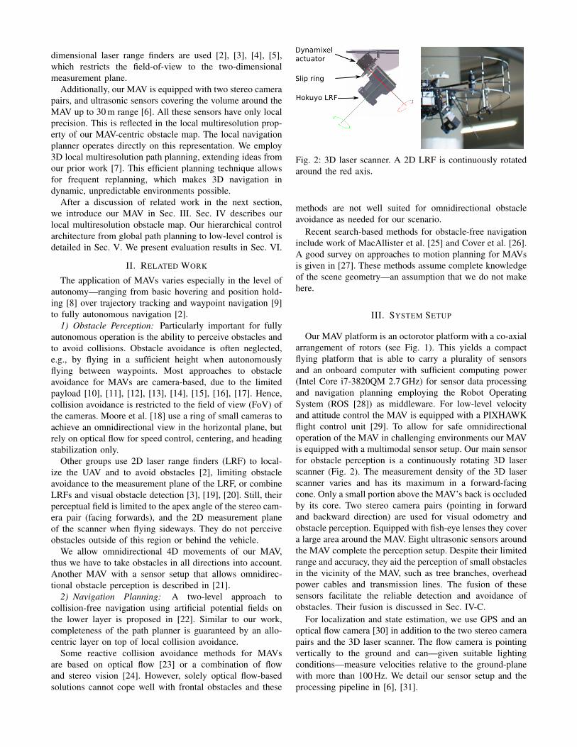
Fig. 3: We aggregate 3D laser scans (middle) into local grid-based obstacle maps. The right image shows a resulting mapfrom the indoor environment in the left image. The scans are aggregated over 1 s.
IV. OBSTACLE PERCEPTION
In order to fuse and accumulate laser range measure-ments, we construct MAV-centric obstacle maps. For eachmeasurement and the corresponding 3D point, the individualcell of the map is marked as occupied. An exemplary mapfrom an indoor environment is shown in Fig. 3. The map isused by our path planning and obstacle avoidance algorithmsdescribed in subsequent sections.
A. Local Multiresolution Map
We use a hybrid local multiresolution map that representsboth occupancy information and the individual distance mea-surements. The most recent measurements are stored in ringbuffers within grid cells that increase in size with distancefrom the robot’s center. Thus, we gain a high resolution in theclose proximity to the sensor and a lower resolution far awayfrom our robot, which correlates with the sensor’s character-istics in relative distance accuracy and measurement density.Compared to uniform grid-based maps, multiresolution leadsto the use of fewer grid cells without loosing informationand consequently results in lower computational costs. Fig. 4shows our multiresolution grid-based map.
We aim for efficient map management for translation androtation. Therefore, individual grid cells are stored in a ringbuffer to allow shifting of elements in constant time.
We interlace multiple ring buffers to obtain a map withthree dimensions. The length of the ring buffers depends onthe resolution and the size of the map. In case of a translationof the MAV, the ring buffers are shifted whenever necessaryto maintain the egocentric property of the map.
B. Scan Registration
To compensate the sensor’s motion during scan acquisi-tion, we incorporate a visual odometry estimate from twopairs of wide-angle stereo cameras [32]. This 6D motionestimate is used to assemble the individual 2D scan lines ofeach a half rotation to a 3D scan.
We register consecutive 3D scans by matching Gaussianpoint statistics in grid cells (surfels) between local multires-olution grid maps [33]. We assign surfels in a probabilistic
way within a Gaussian mixture model (GMM) in a coarse-to-fine fashion, which is facilitated by the multiresolutionproperty of our map.
After the new scan has been registered to the map, the newmeasurements are added, replacing the oldest measurements.We also implement an aging of the individual grid cells,which leads to the abandoning of outdated measurements infree or unobserved volumes.
C. Occupancy Mapping
The individual sensors of our MAV have differentstrengths and weaknesses. In order to perceive as manyobstacles as possible it is necessary to fuse the measurementsadequately into a single map. We collect these measurementsin an occupancy grid maintaining occupancy probabilities.We fuse measurements from the 3D laser scanner, from wide-angle stereo cameras and from ultrasound sensors. Fig. 5shows an example of an outdoor scenario where fusing laserrange measurements with dense stereo [34] allows for per-ception of challenging obstacles. Besides very thin obstaclessuch as a cable in the previous example, transparent objectsare demanding for reliable obstacle perception. Fig. 6 showshow fusing measurements from our 3D laser scanner withultrasound measurements allows for detecting transparentobstacles, like windows.
V. PLANNING
To reduce the planning complexity we divide the overallplanning problem into multiple problems with different levelsof abstractions. This is represented by a hierarchical controlarchitecture for our MAV, with slower deliberative plannersthat solve complex path and mission planning problems onthe upper layers and high-frequency reactive controllers onthe lower layers (see Fig. 7).
A. Mission and Global Path Planning
The topmost layers are a mission planner and a globalpath planner using a static representation of the environmentderived from a 3D city model and a digital elevation model,depicted in Fig. 8(a). This model is stored efficiently inan OctoMap [35]. The global environment model does notchange during a single observation mission. Hence, the
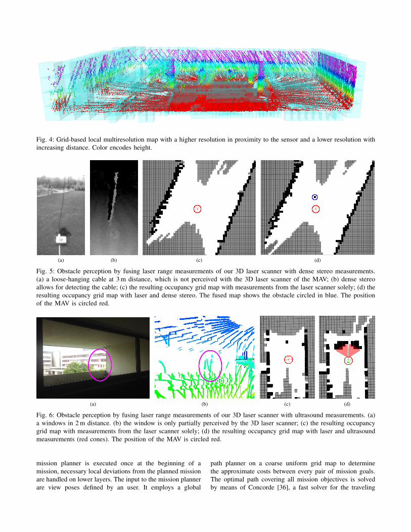
Fig. 4: Grid-based local multiresolution map with a higher resolution in proximity to the sensor and a lower resolution withincreasing distance. Color encodes height.
(a) (b) (c) (d)
Fig. 5: Obstacle perception by fusing laser range measurements of our 3D laser scanner with dense stereo measurements.(a) a loose-hanging cable at 3 m distance, which is not perceived with the 3D laser scanner of the MAV; (b) dense stereoallows for detecting the cable; (c) the resulting occupancy grid map with measurements from the laser scanner solely; (d) theresulting occupancy grid map with laser and dense stereo. The fused map shows the obstacle circled in blue. The positionof the MAV is circled red.
(a) (b) (c) (d)
Fig. 6: Obstacle perception by fusing laser range measurements of our 3D laser scanner with ultrasound measurements. (a)a windows in 2 m distance. (b) the window is only partially perceived by the 3D laser scanner; (c) the resulting occupancygrid map with measurements from the laser scanner solely; (d) the resulting occupancy grid map with laser and ultrasoundmeasurements (red cones). The position of the MAV is circled red.
mission planner is executed once at the beginning of amission, necessary local deviations from the planned missionare handled on lower layers. The input to the mission plannerare view poses defined by an user. It employs a global
path planner on a coarse uniform grid map to determinethe approximate costs between every pair of mission goals.The optimal path covering all mission objectives is solvedby means of Concorde [36], a fast solver for the traveling
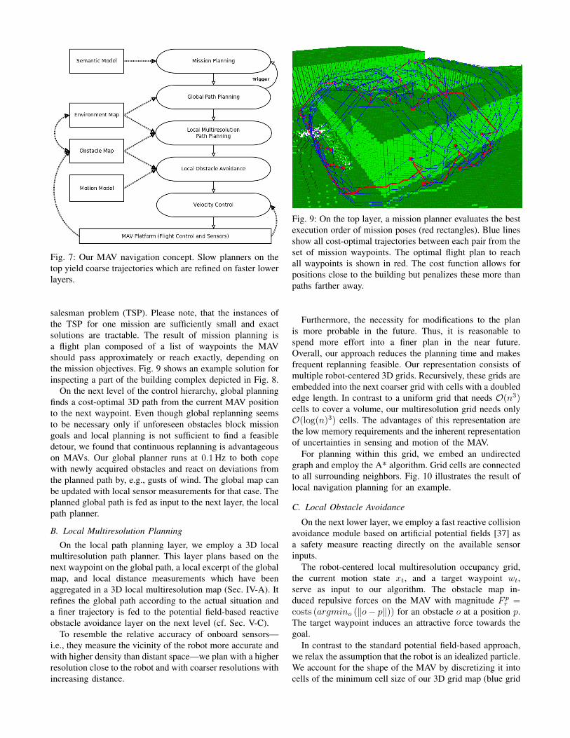
Fig. 7: Our MAV navigation concept. Slow planners on thetop yield coarse trajectories which are refined on faster lowerlayers.
salesman problem (TSP). Please note, that the instances ofthe TSP for one mission are sufficiently small and exactsolutions are tractable. The result of mission planning isa flight plan composed of a list of waypoints the MAVshould pass approximately or reach exactly, depending onthe mission objectives. Fig. 9 shows an example solution forinspecting a part of the building complex depicted in Fig. 8.
On the next level of the control hierarchy, global planningfinds a cost-optimal 3D path from the current MAV positionto the next waypoint. Even though global replanning seemsto be necessary only if unforeseen obstacles block missiongoals and local planning is not sufficient to find a feasibledetour, we found that continuous replanning is advantageouson MAVs. Our global planner runs at 0.1Hz to both copewith newly acquired obstacles and react on deviations fromthe planned path by, e.g., gusts of wind. The global map canbe updated with local sensor measurements for that case. Theplanned global path is fed as input to the next layer, the localpath planner.
B. Local Multiresolution Planning
On the local path planning layer, we employ a 3D localmultiresolution path planner. This layer plans based on thenext waypoint on the global path, a local excerpt of the globalmap, and local distance measurements which have beenaggregated in a 3D local multiresolution map (Sec. IV-A). Itrefines the global path according to the actual situation anda finer trajectory is fed to the potential field-based reactiveobstacle avoidance layer on the next level (cf. Sec. V-C).
To resemble the relative accuracy of onboard sensors—i.e., they measure the vicinity of the robot more accurate andwith higher density than distant space—we plan with a higherresolution close to the robot and with coarser resolutions withincreasing distance.
Fig. 9: On the top layer, a mission planner evaluates the bestexecution order of mission poses (red rectangles). Blue linesshow all cost-optimal trajectories between each pair from theset of mission waypoints. The optimal flight plan to reachall waypoints is shown in red. The cost function allows forpositions close to the building but penalizes these more thanpaths farther away.
Furthermore, the necessity for modifications to the planis more probable in the future. Thus, it is reasonable tospend more effort into a finer plan in the near future.Overall, our approach reduces the planning time and makesfrequent replanning feasible. Our representation consists ofmultiple robot-centered 3D grids. Recursively, these grids areembedded into the next coarser grid with cells with a doublededge length. In contrast to a uniform grid that needs O(n3)cells to cover a volume, our multiresolution grid needs onlyO(log(n)3) cells. The advantages of this representation arethe low memory requirements and the inherent representationof uncertainties in sensing and motion of the MAV.
For planning within this grid, we embed an undirectedgraph and employ the A* algorithm. Grid cells are connectedto all surrounding neighbors. Fig. 10 illustrates the result oflocal navigation planning for an example.
C. Local Obstacle Avoidance
On the next lower layer, we employ a fast reactive collisionavoidance module based on artificial potential fields [37] asa safety measure reacting directly on the available sensorinputs.
The robot-centered local multiresolution occupancy grid,the current motion state xt, and a target waypoint wt,serve as input to our algorithm. The obstacle map in-duced repulsive forces on the MAV with magnitude F p
r =costs (argmino (‖o− p‖)) for an obstacle o at a position p.The target waypoint induces an attractive force towards thegoal.
In contrast to the standard potential field-based approach,we relax the assumption that the robot is an idealized particle.We account for the shape of the MAV by discretizing it intocells of the minimum cell size of our 3D grid map (blue grid
(a) OctoMap derived from the 3D city model anda digital elevation model.
(b) Local laser scan from the environment, in-cluding a building and vegetation (blue circle).Measurements on the MAV itself are circled red.
(c) Photo of the scanned environment.
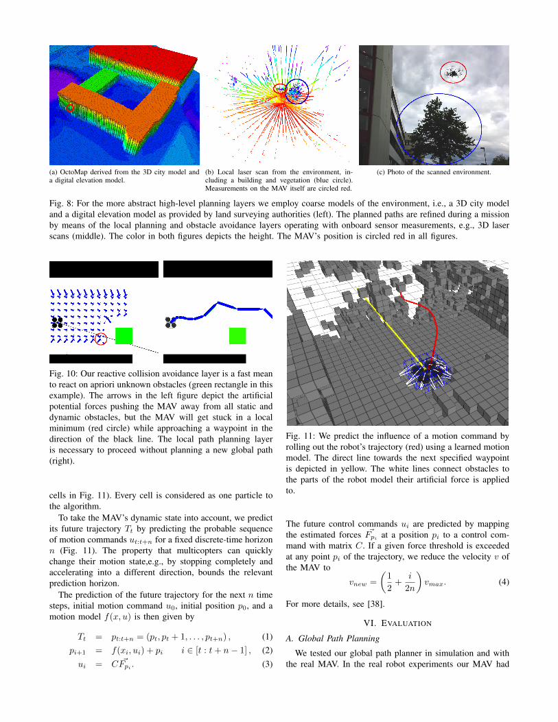
Fig. 8: For the more abstract high-level planning layers we employ coarse models of the environment, i.e., a 3D city modeland a digital elevation model as provided by land surveying authorities (left). The planned paths are refined during a missionby means of the local planning and obstacle avoidance layers operating with onboard sensor measurements, e.g., 3D laserscans (middle). The color in both figures depicts the height. The MAV’s position is circled red in all figures.
Fig. 10: Our reactive collision avoidance layer is a fast meanto react on apriori unknown obstacles (green rectangle in thisexample). The arrows in the left figure depict the artificialpotential forces pushing the MAV away from all static anddynamic obstacles, but the MAV will get stuck in a localminimum (red circle) while approaching a waypoint in thedirection of the black line. The local path planning layeris necessary to proceed without planning a new global path(right).
cells in Fig. 11). Every cell is considered as one particle tothe algorithm.
To take the MAV’s dynamic state into account, we predictits future trajectory Tt by predicting the probable sequenceof motion commands ut:t+n for a fixed discrete-time horizonn (Fig. 11). The property that multicopters can quicklychange their motion state,e.g., by stopping completely andaccelerating into a different direction, bounds the relevantprediction horizon.
The prediction of the future trajectory for the next n timesteps, initial motion command u0, initial position p0, and amotion model f(x, u) is then given by
Tt = pt:t+n = (pt, pt + 1, . . . , pt+n) , (1)pi+1 = f(xi, ui) + pi i ∈ [t : t+ n− 1] , (2)
ui = C ~Fpi. (3)
Fig. 11: We predict the influence of a motion command byrolling out the robot’s trajectory (red) using a learned motionmodel. The direct line towards the next specified waypointis depicted in yellow. The white lines connect obstacles tothe parts of the robot model their artificial force is appliedto.
The future control commands ui are predicted by mappingthe estimated forces ~Fpi
at a position pi to a control com-mand with matrix C. If a given force threshold is exceededat any point pi of the trajectory, we reduce the velocity v ofthe MAV to
vnew =
(1
2+
i
2n
)vmax. (4)
For more details, see [38].
VI. EVALUATION
A. Global Path Planning
We tested our global path planner in simulation and withthe real MAV. In the real robot experiments our MAV had
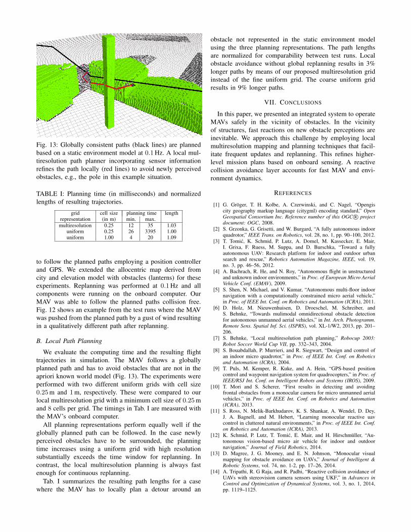
Fig. 13: Globally consistent paths (black lines) are plannedbased on a static environment model at 0.1Hz. A local mul-tiresolution path planner incorporating sensor informationrefines the path locally (red lines) to avoid newly perceivedobstacles, e.g., the pole in this example situation.
TABLE I: Planning time (in milliseconds) and normalizedlengths of resulting trajectories.
grid cell size planning time lengthrepresentation (in m) min. max.multiresolution 0.25 12 35 1.03
uniform 0.25 26 3395 1.00uniform 1.00 4 20 1.09
to follow the planned paths employing a position controllerand GPS. We extended the allocentric map derived fromcity and elevation model with obstacles (lanterns) for theseexperiments. Replanning was performed at 0.1Hz and allcomponents were running on the onboard computer. OurMAV was able to follow the planned paths collision free.Fig. 12 shows an example from the test runs where the MAVwas pushed from the planned path by a gust of wind resultingin a qualitatively different path after replanning.
B. Local Path Planning
We evaluate the computing time and the resulting flighttrajectories in simulation. The MAV follows a globallyplanned path and has to avoid obstacles that are not in theapriori known world model (Fig. 13). The experiments wereperformed with two different uniform grids with cell size0.25m and 1m, respectively. These were compared to ourlocal multiresolution grid with a minimum cell size of 0.25mand 8 cells per grid. The timings in Tab. I are measured withthe MAV’s onboard computer.
All planning representations perform equally well if theglobally planned path can be followed. In the case newlyperceived obstacles have to be surrounded, the planningtime increases using a uniform grid with high resolutionsubstantially exceeds the time window for replanning. Incontrast, the local multiresolution planning is always fastenough for continuous replanning.
Tab. I summarizes the resulting path lengths for a casewhere the MAV has to locally plan a detour around an
obstacle not represented in the static environment modelusing the three planning representations. The path lengthsare normalized for comparability between test runs. Localobstacle avoidance without global replanning results in 3%longer paths by means of our proposed multiresolution gridinstead of the fine uniform grid. The coarse uniform gridresults in 9% longer paths.
VII. CONCLUSIONS
In this paper, we presented an integrated system to operateMAVs safely in the vicinity of obstacles. In the vicinityof structures, fast reactions on new obstacle perceptions areinevitable. We approach this challenge by employing localmultiresolution mapping and planning techniques that facil-itate frequent updates and replanning. This refines higher-level mission plans based on onboard sensing. A reactivecollision avoidance layer accounts for fast MAV and envi-ronment dynamics.
REFERENCES
[1] G. Gröger, T. H. Kolbe, A. Czerwinski, and C. Nagel, “Opengiscity geography markup language (citygml) encoding standard,” OpenGeospatial Consortium Inc. Reference number of this OGC R© projectdocument: OGC, 2008.
[2] S. Grzonka, G. Grisetti, and W. Burgard, “A fully autonomous indoorquadrotor,” IEEE Trans. on Robotics, vol. 28, no. 1, pp. 90–100, 2012.
[3] T. Tomic, K. Schmid, P. Lutz, A. Domel, M. Kassecker, E. Mair,I. Grixa, F. Ruess, M. Suppa, and D. Burschka, “Toward a fullyautonomous UAV: Research platform for indoor and outdoor urbansearch and rescue,” Robotics Automation Magazine, IEEE, vol. 19,no. 3, pp. 46–56, 2012.
[4] A. Bachrach, R. He, and N. Roy, “Autonomous flight in unstructuredand unknown indoor environments,” in Proc. of European Micro AerialVehicle Conf. (EMAV), 2009.
[5] S. Shen, N. Michael, and V. Kumar, “Autonomous multi-floor indoornavigation with a computationally constrained micro aerial vehicle,”in Proc. of IEEE Int. Conf. on Robotics and Automation (ICRA), 2011.
[6] D. Holz, M. Nieuwenhuisen, D. Droeschel, M. Schreiber, andS. Behnke, “Towards mulimodal omnidirectional obstacle detectionfor autonomous unmanned aerial vehicles,” in Int. Arch. Photogramm.Remote Sens. Spatial Inf. Sci. (ISPRS), vol. XL-1/W2, 2013, pp. 201–206.
[7] S. Behnke, “Local multiresolution path planning,” Robocup 2003:Robot Soccer World Cup VII, pp. 332–343, 2004.
[8] S. Bouabdallah, P. Murrieri, and R. Siegwart, “Design and control ofan indoor micro quadrotor,” in Proc. of IEEE Int. Conf. on Roboticsand Automation (ICRA), 2004.
[9] T. Puls, M. Kemper, R. Kuke, and A. Hein, “GPS-based positioncontrol and waypoint navigation system for quadrocopters,” in Proc. ofIEEE/RSJ Int. Conf. on Intelligent Robots and Systems (IROS), 2009.
[10] T. Mori and S. Scherer, “First results in detecting and avoidingfrontal obstacles from a monocular camera for micro unmanned aerialvehicles,” in Proc. of IEEE Int. Conf. on Robotics and Automation(ICRA), 2013.
[11] S. Ross, N. Melik-Barkhudarov, K. S. Shankar, A. Wendel, D. Dey,J. A. Bagnell, and M. Hebert, “Learning monocular reactive uavcontrol in cluttered natural environments,” in Proc. of IEEE Int. Conf.on Robotics and Automation (ICRA), 2013.
[12] K. Schmid, P. Lutz, T. Tomic, E. Mair, and H. Hirschmüller, “Au-tonomous vision-based micro air vehicle for indoor and outdoornavigation,” Journal of Field Robotics, 2014.
[13] D. Magree, J. G. Mooney, and E. N. Johnson, “Monocular visualmapping for obstacle avoidance on UAVs,” Journal of Intelligent &Robotic Systems, vol. 74, no. 1-2, pp. 17–26, 2014.
[14] A. Tripathi, R. G Raja, and R. Padhi, “Reactive collision avoidance ofUAVs with stereovision camera sensors using UKF,” in Advances inControl and Optimization of Dynamical Systems, vol. 3, no. 1, 2014,pp. 1119–1125.
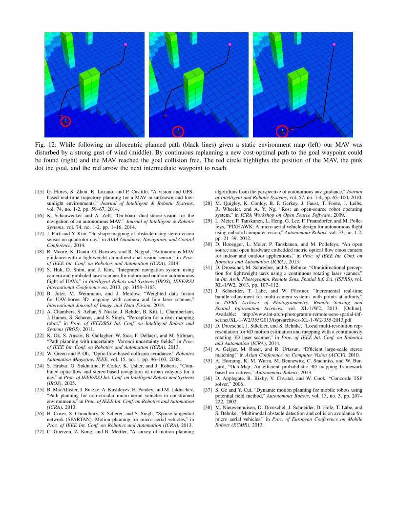
Fig. 12: While following an allocentric planned path (black lines) given a static environment map (left) our MAV wasdisturbed by a strong gust of wind (middle). By continuous replanning a new cost-optimal path to the goal waypoint couldbe found (right) and the MAV reached the goal collision free. The red circle highlights the position of the MAV, the pinkdot the goal, and the red arrow the next intermediate waypoint to reach.
[15] G. Flores, S. Zhou, R. Lozano, and P. Castillo, “A vision and GPS-based real-time trajectory planning for a MAV in unknown and low-sunlight environments,” Journal of Intelligent & Robotic Systems,vol. 74, no. 1-2, pp. 59–67, 2014.
[16] K. Schauwecker and A. Zell, “On-board dual-stereo-vision for thenavigation of an autonomous MAV,” Journal of Intelligent & RoboticSystems, vol. 74, no. 1-2, pp. 1–16, 2014.
[17] J. Park and Y. Kim, “3d shape mapping of obstacle using stereo visionsensor on quadrotor uav,” in AIAA Guidance, Navigation, and ControlConference, 2014.
[18] R. Moore, K. Dantu, G. Barrows, and R. Nagpal, “Autonomous MAVguidance with a lightweight omnidirectional vision sensor,” in Proc.of IEEE Int. Conf. on Robotics and Automation (ICRA), 2014.
[19] S. Huh, D. Shim, and J. Kim, “Integrated navigation system usingcamera and gimbaled laser scanner for indoor and outdoor autonomousflight of UAVs,” in Intelligent Robots and Systems (IROS), IEEE/RSJInternational Conference on, 2013, pp. 3158–3163.
[20] B. Jutzi, M. Weinmann, and J. Meidow, “Weighted data fusionfor UAV-borne 3D mapping with camera and line laser scanner,”International Journal of Image and Data Fusion, 2014.
[21] A. Chambers, S. Achar, S. Nuske, J. Rehder, B. Kitt, L. Chamberlain,J. Haines, S. Scherer, , and S. Singh, “Perception for a river mappingrobot,” in Proc. of IEEE/RSJ Int. Conf. on Intelligent Robots andSystems (IROS), 2011.
[22] K. Ok, S. Ansari, B. Gallagher, W. Sica, F. Dellaert, and M. Stilman,“Path planning with uncertainty: Voronoi uncertainty fields,” in Proc.of IEEE Int. Conf. on Robotics and Automation (ICRA), 2013.
[23] W. Green and P. Oh, “Optic-flow-based collision avoidance,” RoboticsAutomation Magazine, IEEE, vol. 15, no. 1, pp. 96–103, 2008.
[24] S. Hrabar, G. Sukhatme, P. Corke, K. Usher, and J. Roberts, “Com-bined optic-flow and stereo-based navigation of urban canyons for auav,” in Proc. of IEEE/RSJ Int. Conf. on Intelligent Robots and Systems(IROS), 2005.
[25] B. MacAllister, J. Butzke, A. Kushleyev, H. Pandey, and M. Likhachev,“Path planning for non-circular micro aerial vehicles in constrainedenvironments,” in Proc. of IEEE Int. Conf. on Robotics and Automation(ICRA), 2013.
[26] H. Cover, S. Choudhury, S. Scherer, and S. Singh, “Sparse tangentialnetwork (SPARTAN): Motion planning for micro aerial vehicles,” inProc. of IEEE Int. Conf. on Robotics and Automation (ICRA), 2013.
[27] C. Goerzen, Z. Kong, and B. Mettler, “A survey of motion planning
algorithms from the perspective of autonomous uav guidance,” Journalof Intelligent and Robotic Systems, vol. 57, no. 1-4, pp. 65–100, 2010.
[28] M. Quigley, K. Conley, B. P. Gerkey, J. Faust, T. Foote, J. Leibs,R. Wheeler, and A. Y. Ng, “Ros: an open-source robot operatingsystem,” in ICRA Workshop on Open Source Software, 2009.
[29] L. Meier, P. Tanskanen, L. Heng, G. Lee, F. Fraundorfer, and M. Polle-feys, “PIXHAWK: A micro aerial vehicle design for autonomous flightusing onboard computer vision,” Autonomous Robots, vol. 33, no. 1-2,pp. 21–39, 2012.
[30] D. Honegger, L. Meier, P. Tanskanen, and M. Pollefeys, “An opensource and open hardware embedded metric optical flow cmos camerafor indoor and outdoor applications,” in Proc. of IEEE Int. Conf. onRobotics and Automation (ICRA), 2013.
[31] D. Droeschel, M. Schreiber, and S. Behnke, “Omnidirectional percep-tion for lightweight uavs using a continuous rotating laser scanner,”in Int. Arch. Photogramm. Remote Sens. Spatial Inf. Sci. (ISPRS), vol.XL-1/W2, 2013, pp. 107–112.
[32] J. Schneider, T. Läbe, and W. Förstner, “Incremental real-timebundle adjustment for multi-camera systems with points at infinity,”in ISPRS Archives of Photogrammetry, Remote Sensing andSpatial Information Sciences, vol. XL-1/W2, 2013. [Online].Available: http://www.int-arch-photogramm-remote-sens-spatial-inf-sci.net/XL-1-W2/355/2013/isprsarchives-XL-1-W2-355-2013.pdf
[33] D. Droeschel, J. Stückler, and S. Behnke, “Local multi-resolution rep-resentation for 6D motion estimation and mapping with a continuouslyrotating 3D laser scanner,” in Proc. of IEEE Int. Conf. on Roboticsand Automation (ICRA), 2014.
[34] A. Geiger, M. Roser, and R. Urtasun, “Efficient large-scale stereomatching,” in Asian Conference on Computer Vision (ACCV), 2010.
[35] A. Hornung, K. M. Wurm, M. Bennewitz, C. Stachniss, and W. Bur-gard, “OctoMap: An efficient probabilistic 3D mapping frameworkbased on octrees,” Autonomous Robots, 2013.
[36] D. Applegate, R. Bixby, V. Chvatal, and W. Cook, “Concorde TSPsolver,” 2006.
[37] S. Ge and Y. Cui, “Dynamic motion planning for mobile robots usingpotential field method,” Autonomous Robots, vol. 13, no. 3, pp. 207–222, 2002.
[38] M. Nieuwenhuisen, D. Droeschel, J. Schneider, D. Holz, T. Läbe, andS. Behnke, “Multimodal obstacle detection and collision avoidance formicro aerial vehicles,” in Proc. of European Conference on MobileRobots (ECMR), 2013.