Molecular Crystals and Liquid Crystals · Reconfigurable Colloidal Swarms in Nematic Liquid...
12
This article was downloaded by: [UNIVERSITAT DE BARCELONA] On: 07 July 2015, At: 07:45 Publisher: Taylor & Francis Informa Ltd Registered in England and Wales Registered Number: 1072954 Registered office: 5 Howick Place, London, SW1P 1WG Click for updates Molecular Crystals and Liquid Crystals Publication details, including instructions for authors and subscription information: http://www.tandfonline.com/loi/gmcl20 Reconfigurable Swarms of Colloidal Particles Electrophoretically Driven in Nematic Liquid Crystals Sergi Hernàndez-Navarro ac , Pietro Tierno bc , Jordi Ignés-Mullol ac & Francesc Sagués ac a Department of Physical Chemistry, Universitat de Barcelona, Barcelona, Catalonia, Spain b Department of Structure and Constituents of Matter, Universitat de Barcelona, Barcelona, Catalonia, Spain c Institute of Nanoscience and Nanotechnogy, Universitat de Barcelona, Catalonia, Spain Published online: 06 Jul 2015. To cite this article: Sergi Hernàndez-Navarro, Pietro Tierno, Jordi Ignés-Mullol & Francesc Sagués (2015) Reconfigurable Swarms of Colloidal Particles Electrophoretically Driven in Nematic Liquid Crystals, Molecular Crystals and Liquid Crystals, 610:1, 163-172, DOI: 10.1080/15421406.2015.1025635 To link to this article: http://dx.doi.org/10.1080/15421406.2015.1025635 PLEASE SCROLL DOWN FOR ARTICLE Taylor & Francis makes every effort to ensure the accuracy of all the information (the “Content”) contained in the publications on our platform. However, Taylor & Francis, our agents, and our licensors make no representations or warranties whatsoever as to the accuracy, completeness, or suitability for any purpose of the Content. Any opinions and views expressed in this publication are the opinions and views of the authors, and are not the views of or endorsed by Taylor & Francis. The accuracy of the Content should not be relied upon and should be independently verified with primary sources of information. Taylor and Francis shall not be liable for any losses, actions, claims, proceedings, demands, costs, expenses, damages, and other liabilities whatsoever or howsoever caused arising directly or indirectly in connection with, in relation to or arising out of the use of the Content. This article may be used for research, teaching, and private study purposes. Any substantial or systematic reproduction, redistribution, reselling, loan, sub-licensing, systematic supply, or distribution in any form to anyone is expressly forbidden. Terms &
Transcript of Molecular Crystals and Liquid Crystals · Reconfigurable Colloidal Swarms in Nematic Liquid...

This article was downloaded by: [UNIVERSITAT DE BARCELONA]On: 07 July 2015, At: 07:45Publisher: Taylor & FrancisInforma Ltd Registered in England and Wales Registered Number: 1072954 Registeredoffice: 5 Howick Place, London, SW1P 1WG
Click for updates
Molecular Crystals and Liquid CrystalsPublication details, including instructions for authors andsubscription information:http://www.tandfonline.com/loi/gmcl20
Reconfigurable Swarms of ColloidalParticles Electrophoretically Driven inNematic Liquid CrystalsSergi Hernàndez-Navarroac, Pietro Tiernobc, Jordi Ignés-Mullolac &Francesc Saguésac
a Department of Physical Chemistry, Universitat de Barcelona,Barcelona, Catalonia, Spainb Department of Structure and Constituents of Matter, Universitat deBarcelona, Barcelona, Catalonia, Spainc Institute of Nanoscience and Nanotechnogy, Universitat deBarcelona, Catalonia, SpainPublished online: 06 Jul 2015.
To cite this article: Sergi Hernàndez-Navarro, Pietro Tierno, Jordi Ignés-Mullol & Francesc Sagués(2015) Reconfigurable Swarms of Colloidal Particles Electrophoretically Driven in Nematic LiquidCrystals, Molecular Crystals and Liquid Crystals, 610:1, 163-172, DOI: 10.1080/15421406.2015.1025635
To link to this article: http://dx.doi.org/10.1080/15421406.2015.1025635
PLEASE SCROLL DOWN FOR ARTICLE
Taylor & Francis makes every effort to ensure the accuracy of all the information (the“Content”) contained in the publications on our platform. However, Taylor & Francis,our agents, and our licensors make no representations or warranties whatsoever as tothe accuracy, completeness, or suitability for any purpose of the Content. Any opinionsand views expressed in this publication are the opinions and views of the authors,and are not the views of or endorsed by Taylor & Francis. The accuracy of the Contentshould not be relied upon and should be independently verified with primary sourcesof information. Taylor and Francis shall not be liable for any losses, actions, claims,proceedings, demands, costs, expenses, damages, and other liabilities whatsoever orhowsoever caused arising directly or indirectly in connection with, in relation to or arisingout of the use of the Content.
This article may be used for research, teaching, and private study purposes. Anysubstantial or systematic reproduction, redistribution, reselling, loan, sub-licensing,systematic supply, or distribution in any form to anyone is expressly forbidden. Terms &

Conditions of access and use can be found at http://www.tandfonline.com/page/terms-and-conditions
Dow
nloa
ded
by [
UN
IVE
RSI
TA
T D
E B
AR
CE
LO
NA
] at
07:
45 0
7 Ju
ly 2
015

Mol. Cryst. Liq. Cryst., Vol. 610: pp. 163–172, 2015Copyright © Taylor & Francis Group, LLCISSN: 1542-1406 print/1563-5287 onlineDOI: 10.1080/15421406.2015.1025635
Reconfigurable Swarms of Colloidal ParticlesElectrophoretically Driven in Nematic
Liquid Crystals
SERGI HERNANDEZ-NAVARRO,1,3 PIETRO TIERNO,2,3
JORDI IGNES-MULLOL,1,3,∗ AND FRANCESC SAGUES1,3
1Department of Physical Chemistry, Universitat de Barcelona, Barcelona,Catalonia, Spain2Department of Structure and Constituents of Matter, Universitat de Barcelona,Barcelona, Catalonia, Spain3Institute of Nanoscience and Nanotechnogy, Universitat de Barcelona,Catalonia, Spain
We present experiments where anisometric colloidal microparticles dispersed in a ne-matic liquid crystal cell with homeotropic anchoring conditions are dynamically as-sembled by means of liquid-crystal-enabled electrophoresis (LCEEP) using an ACelectric field perpendicular to the confining plates. A nematic host with negative dielec-tric anisotropy leads to a driving force parallel to the cell plates. We take advantageof the resulting gliding anchoring conditions and the degeneracy in the direction ofparticle motion to design reconfigurable trajectories using a photosensitive anchoringlayer (azosilane self-assembled monolayer), as the particle trajectory follows the localdirector orientation.
Keywords electrophoresis; colloids; self-assembly; azobenzene; swarms
Introduction
The assembly and transport of microscopic entities, such as particles, droplets, or mi-croorganisms, is a permanently motivating challenge in Soft Materials science. Colloidassembly can be tuned by controlling their size [1] and shape [2], their surface chemistry[3, 4], or by suspending the inclusions in a liquid crystal [5]. Optical trapping techniquesare often employed to achieve direct control over the placement of colloidal inclusions,and holographic tweezers allow to extend such control to a few hundreds of particles [6],although the technique is limited by the field of view of the optical system. Recently, newperspectives for the assembly and transport of colloids through the interplay of phoreticand osmotic mechanisms have been demonstrated [7, 8].
When electric fields are involved, Direct Current (DC) driving of colloids can leadto unwanted effects such as ion migration or electrolysis, which can be avoided by using
∗Address correspondence to Jordi Ignes-Mullol, Universitat de Barcelona, Marti i Franques1 08028, Barcelona, Catalonia, Spain. E-mail: [email protected]
Color versions of one or more of the figures in the article can be found online atwww.tandfonline.com/gmcl.
163
Dow
nloa
ded
by [
UN
IVE
RSI
TA
T D
E B
AR
CE
LO
NA
] at
07:
45 0
7 Ju
ly 2
015

164 S. Hernandez-Navarro et al.
Alternating Current (AC) fields. For AC driving to be effective, the fore-aft symmetry ofindividual particles must be broken. This has been realized with metallo-dielectric Janusparticles driven in aqueous media [9], where symmetry is broken by the particle inhomoge-neous surface. More recently, the use of a nematic liquid crystal (NLC) host has showed thecapability to transport homogeneous solid [10–12] or liquid inclusions [13] along the localnematic director. In this Liquid Crystal Enabled Electrophoresis (LCEEP), symmetry isbroken by the NLC director field around the inclusion, which must have a nonzero dipolarcomponent in order for LCEEP propulsion to be effective. When a microscale inclusionis dispersed in a NLC, the distortion of the director field leads to the formation of de-fects around the particle, with a configuration that depends on the particle shape and onthe anchoring conditions. For spherical particles, tangential boundary conditions result inthe formation of two surface defects (boojums) leading to a quadrupolar symmetry of thedirector, while homeotropic boundary conditions lead either to an equatorial ring defect(quadrupolar symmetry) or to a single hyperbolic hedgehog point defect (dipolar symme-try) [5, 14, 15]. LCEEP has been demonstrated with spherical solid or liquid inclusions,and the required dipolar symmetry has been achieved by means of suitable particle surfacefunctionalization. However, it may be challenging to prepare a sample with a large numberof spherical inclusions featuring a single hedgehog point defect configuration.
In this work we use anisometric pear-shaped solid inclusions with tangential boundaryconditions embedded in a NLC. Particle shape guarantees non-quadrupolar elastic distor-tions of the director field, thus enabling LCEEP propulsion when subjected to an externalAC electric field. By employing photoelastic modulations of the NLC matrix we are able toseparate particle driving and steering [16], demonstrating an unparalleled ability to controlthe assembly of arbitrarily large ensembles of inclusions, and to drive the formed clustersas swarms along reconfigurable paths.
Experimental Section
Preparation of Photosensitive Glass-ITO Plates
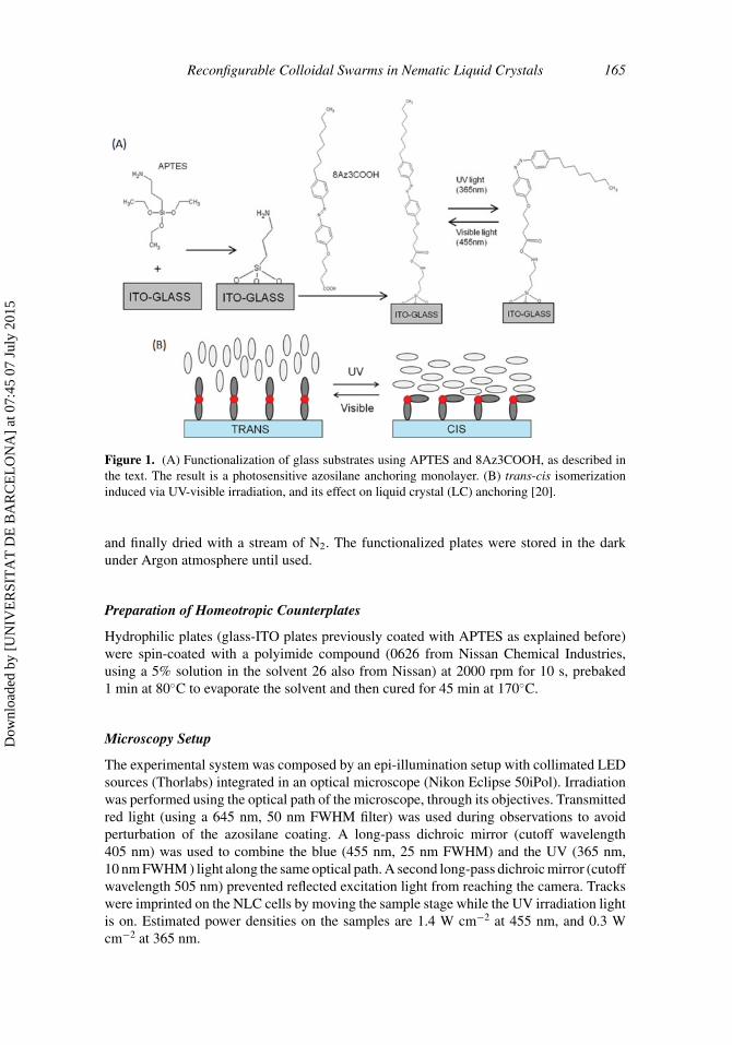
NLC cells were prepared using 0.7 mm thick microscope slides of size 15×25 mm2, coatedwith a thin layer of indium-tin oxide (ITO) with a sheet resistance of 100 � per square(VisionTek Systems). Photosensitive glass-ITO plates were prepared as shown in Fig. 1.In a first step, clean and dry plates where coated with a self-assembled monolayer of(3-aminopropyl) triethoxysilane (APTES, Sigma-Aldrich) [17], and subsequently rinsedwith toluene, methanol (99.9%, Scharlau) and ultrapure water. Plates were then stored in adesiccator for 2 h before further use. In a second step, an amide bond was formed betweenthe amino terminal group of APTES and the custom-synthesized azobenzene 4-octyl-4′-(carboxy-3-propyloxy)azobenzene (8Az3COOH) [18]. This bond formation was typicallyperformed [19] in a dimethylformamide (DMF, peptide synthesis grade, Scharlau) mediumusing pyBOP (>97%, Fluka) as the coupling agent. APTES-functionalized plates wererinsed in DMF and submerged in a Petri dish with 5 ml of DMF to which 1 ml of DMFcontaining 0.6 mg of 8Az3COOH and 1 ml of DMF containing 1.0 mg of pyBOP wereadded. Additionally, 6 μL of N-ethyldiisopropylamine (>98%, Fluka) were added to obtainthe necessary alkaline environment. The system was kept in the dark and under stirringovernight. The plates were subsequently rinsed first with DMF and then with MilliQ water,
Dow
nloa
ded
by [
UN
IVE
RSI
TA
T D
E B
AR
CE
LO
NA
] at
07:
45 0
7 Ju
ly 2
015
Reconfigurable Colloidal Swarms in Nematic Liquid Crystals 165
Figure 1. (A) Functionalization of glass substrates using APTES and 8Az3COOH, as described inthe text. The result is a photosensitive azosilane anchoring monolayer. (B) trans-cis isomerizationinduced via UV-visible irradiation, and its effect on liquid crystal (LC) anchoring [20].
and finally dried with a stream of N2. The functionalized plates were stored in the darkunder Argon atmosphere until used.
Preparation of Homeotropic Counterplates
Hydrophilic plates (glass-ITO plates previously coated with APTES as explained before)were spin-coated with a polyimide compound (0626 from Nissan Chemical Industries,using a 5% solution in the solvent 26 also from Nissan) at 2000 rpm for 10 s, prebaked1 min at 80◦C to evaporate the solvent and then cured for 45 min at 170◦C.
Microscopy Setup
The experimental system was composed by an epi-illumination setup with collimated LEDsources (Thorlabs) integrated in an optical microscope (Nikon Eclipse 50iPol). Irradiationwas performed using the optical path of the microscope, through its objectives. Transmittedred light (using a 645 nm, 50 nm FWHM filter) was used during observations to avoidperturbation of the azosilane coating. A long-pass dichroic mirror (cutoff wavelength405 nm) was used to combine the blue (455 nm, 25 nm FWHM) and the UV (365 nm,10 nm FWHM ) light along the same optical path. A second long-pass dichroic mirror (cutoffwavelength 505 nm) prevented reflected excitation light from reaching the camera. Trackswere imprinted on the NLC cells by moving the sample stage while the UV irradiation lightis on. Estimated power densities on the samples are 1.4 W cm−2 at 455 nm, and 0.3 Wcm−2 at 365 nm.
Dow
nloa
ded
by [
UN
IVE
RSI
TA
T D
E B
AR
CE
LO
NA
] at
07:
45 0
7 Ju
ly 2
015

166 S. Hernandez-Navarro et al.
AC sinusoidal electric fields were applied using a function generator (ISO-TECH IFA730) and an amplifier (TREK model PZD700), via electric contacts to LC cell plates.
Bright field and polarized optical images were captured with an AVT Marlin F-131BCMOS camera controlled with the software AVT SmartView 1.10.2. Digitized images weresubsequently processed and analyzed using software packages ImageJ and IgorPro.
LC Cells Preparation
LC cells were built by gluing together an azosilane-coated plate and a homeotropic counter-plate with strips of polyethylene terephthalate (Mylar, Goodfellow) acting as spacers, ob-taining cell gaps in the range 13–46 μm. Polystyrene anisometric particles (pear-shaped,2×3 μm2 , 3×4 μm2, or 8×10 μm2 Magsphere), initially suspended in water, were redis-persed in methanol. A few microliters of the sonicated methanol dispersion were depositedon top of a small volume of the NLC (MLC-7029, Merck, room temperature properties:�ε(1 kHz) = −3.6, K1 = 16.1 pN, K3 = 15.0 pN), and the solvent was let to evaporate ina desiccator. The NLC dispersion was subsequently agitated in a vortex and sonicated. LCcells were filled by capillary action with freshly prepared dispersions.
Results and Discussion
Photoelastic Modulation of the Liquid Crystal Cells
Without external influences, boundary conditions of the prepared cells lead to uniformhomeotropic anchoring of the NLC, with the dispersed pear-shaped particles aligningfollowing the local director field. By irradiating with UV light, we force the azosilanemonolayer to adopt the cis form leading to planar alignment of the local NLC director [20](Fig. 1B, 2A, 2B).
The unpolarized beam of UV light has a spatial intensity profile with approximately aGaussian shape, which leads to a radial splay arrangement of the NLC director in contactwith the irradiated spot (Fig. 2A, 2B), organized around a central s = +1 point defect.Outside of the spot, the director remains perpendicular to the cell. Application of an externalAC field aligns the negative dielectric anisotropy NLC parallel to the plates everywhere [21].Because of the homeotropic anchoring, the field-induced planar alignment is energeticallydegenerate. However, the in-plane radial boundary conditions imposed by the irradiatedspot break this degeneracy, propagating the pure splay texture radially outwards for severalmillimeters. The induced configuration is stable for days under an AC field, well past thehalf-life for thermal relaxation of the azosilane film, which is about 30 minutes in thissystem.
Liquid-crystal Enabled Electrophoretic Driving
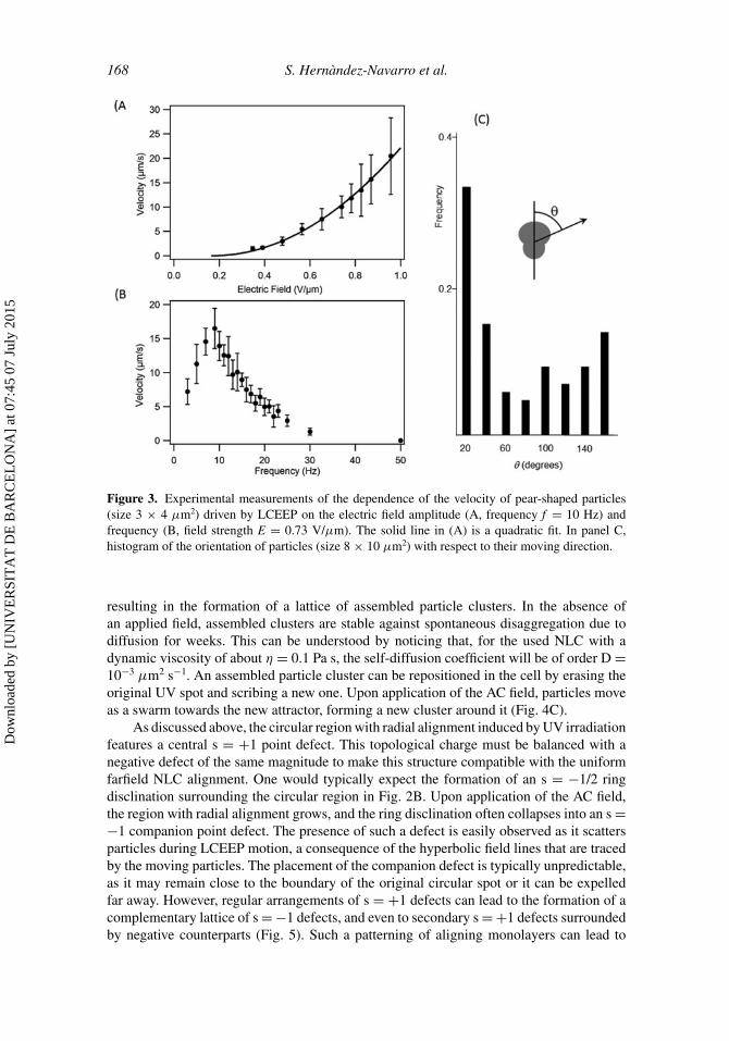
Upon application of the AC field, particles tumble instantaneously following the NLCdirector so that their long axis lays, on average, parallel to the cell plates. Simultaneously,LCEEP sets the particle into motion along the local director at a constant speed, which is abalance between electrophoretic propulsion and viscous drag. Particle speed has a leadingquadratic dependence on the electric field amplitude (Fig. 3A) and features a maximumaround 10 Hz for 3 × 4 μm2 particles (Fig. 3B). These results agree qualitatively with thebehavior of spherical solid [10] or liquid [13] inclusions driven by LCEEP under differentconfigurations. Speed changes drastically with particle size. It is undetectably slow for the
Dow
nloa
ded
by [
UN
IVE
RSI
TA
T D
E B
AR
CE
LO
NA
] at
07:
45 0
7 Ju
ly 2
015

Reconfigurable Colloidal Swarms in Nematic Liquid Crystals 167
Figure 2. (A) Schematics of the cross section of the experimental cell upon irradiation with a UVlight spot. The bottom plate is coated with the azosilane film, which is isomerized into the cis form,leading to hybrid anchoring conditions across the cell gap. (B) Top-view micrograph between crossedpolarizers. The scale bar is 500 μm long. (C) Cross section schematics of the cell upon application ofa sinusoidal electric field between the plates. Red arrows indicate the dominant direction of motion ofthe anisometric particles. (D) Top-view micrograph between crossed polarizers of the configurationin (C). The scale bar is 200 μm long.
smallest particles (2 × 3 μm2), and has significantly lower values that those reported inFig. 3 for the largest particles (8 × 10 μm2).
During propulsion, we find that most particles are oriented so that their symmetryaxis is roughly parallel to the direction of motion, with the larger lobule ahead (Fig. 2C),although there is a significant dispersion in their orientation, as shown in Figure 3C withdata using the largest particles in order to better resolve their orientation. LCEEP arisesfrom the anisotropic ionic mobility around the inclusions, and this, in turn, is modifiedby the defect pattern induced by the inclusion in the surrounding NLC director. Given theparticle geometry in the present case, one would expect the formation of two boojums(surface defects) along the symmetry axis. The fact that particles are dispersed in the NLCwithout annealing it into the isotropic phase might generate pinning on inhomogeneitiespresent on the particles surface, leading to metastable defect arrangements. This mightjustify the anomalous particle orientation we observe during LCEEP motion (Fig. 3C), andthe disordered packing obtained upon particle assembly (see below).
Cluster Assembly and Swarm Transport
The region with radial alignment acts as a basin of attraction for dispersed particles, whichassemble around the original UV-irradiated spot into an arrested aster configuration (Fig. 4).If multiple UV spots are distributed over the sample surface, they compete as attractors,
Dow
nloa
ded
by [
UN
IVE
RSI
TA
T D
E B
AR
CE
LO
NA
] at
07:
45 0
7 Ju
ly 2
015
168 S. Hernandez-Navarro et al.
Figure 3. Experimental measurements of the dependence of the velocity of pear-shaped particles(size 3 × 4 μm2) driven by LCEEP on the electric field amplitude (A, frequency f = 10 Hz) andfrequency (B, field strength E = 0.73 V/μm). The solid line in (A) is a quadratic fit. In panel C,histogram of the orientation of particles (size 8 × 10 μm2) with respect to their moving direction.
resulting in the formation of a lattice of assembled particle clusters. In the absence ofan applied field, assembled clusters are stable against spontaneous disaggregation due todiffusion for weeks. This can be understood by noticing that, for the used NLC with adynamic viscosity of about η = 0.1 Pa s, the self-diffusion coefficient will be of order D =10−3 μm2 s−1. An assembled particle cluster can be repositioned in the cell by erasing theoriginal UV spot and scribing a new one. Upon application of the AC field, particles moveas a swarm towards the new attractor, forming a new cluster around it (Fig. 4C).
As discussed above, the circular region with radial alignment induced by UV irradiationfeatures a central s = +1 point defect. This topological charge must be balanced with anegative defect of the same magnitude to make this structure compatible with the uniformfarfield NLC alignment. One would typically expect the formation of an s = −1/2 ringdisclination surrounding the circular region in Fig. 2B. Upon application of the AC field,the region with radial alignment grows, and the ring disclination often collapses into an s =−1 companion point defect. The presence of such a defect is easily observed as it scattersparticles during LCEEP motion, a consequence of the hyperbolic field lines that are tracedby the moving particles. The placement of the companion defect is typically unpredictable,as it may remain close to the boundary of the original circular spot or it can be expelledfar away. However, regular arrangements of s = +1 defects can lead to the formation of acomplementary lattice of s = −1 defects, and even to secondary s = +1 defects surroundedby negative counterparts (Fig. 5). Such a patterning of aligning monolayers can lead to
Dow
nloa
ded
by [
UN
IVE
RSI
TA
T D
E B
AR
CE
LO
NA
] at
07:
45 0
7 Ju
ly 2
015

Reconfigurable Colloidal Swarms in Nematic Liquid Crystals 169
Figure 4. A radial pattern imprinted on the NLC cell by a UV light spot (Figure 2) attracts dispersedparticles (A) that assemble into an arrested aster-like cluster following centripetal trajectories (B).In (C), the UV light spot has been rewritten 600 μm to the right. Upon application of the AC field(t = 0s), the cluster of particles moves as a swarm towards the center of the new spot.
Figure 5. Micrograph between crossed polarizers of a NLC cell where a lattice of circular spots hasbeen imprinted with a center-to-center distance of about 650 μm. Upon application of the AC field,complementary s = −1 and secondary s = +1 defects (black labels) are formed. The scale bar is300 μm.
Dow
nloa
ded
by [
UN
IVE
RSI
TA
T D
E B
AR
CE
LO
NA
] at
07:
45 0
7 Ju
ly 2
015

170 S. Hernandez-Navarro et al.
Figure 6. (A) Schematics of the cross section of a NLC cell previously irradiated with a UV spot thatis now illuminated at the center with a narrower spot of blue light, which leads to the isomerization ofthe azosilane layer into the trans form. (B) Top view micrograph between crossed polarizers revealinga corona with planar radial alignment. The scale bar is 500 μm. (C) Top view of the spiral textureformed by the NLC director upon application of an AC field. The scale bar is 200 μm. (D) Particlesare attracted to the center of the irradiated spot following spiral trajectories and assemble into arotating mill. The trajectories of three different particles are tracked for the same amount of time.
interesting defect healing scenarios in NLC cells with hybrid anchoring conditions [22,23].
Controlling the Dynamic State of Colloidal Clusters
The LCEEP-induced assembly of colloidal inclusions can be modified from the formationof static aster-like aggregates to rotating mills, where assembled particles rotate at a constantlinear velocity around the center of the aggregate (Fig. 6). This can be achieved by takingadvantage of the higher cost of splay with respect to bend distortions in this NLC, since theelastic constant K1 is 7% higher than K3 (see above). We begin by erasing the central regionof a UV-irradiated spot using a smaller spot of blue light (Fig. 6). With this, in the absenceof electric field, the NLC director features a homeotropic configuration both outside andinside a corona with planar radial alignment.
Upon application of the AC field, the NLC director both inside and outside the ringadopts a degenerate planar alignment because of the homeotropic anchoring conditions. Asexplained above for the full circular spot case (see Fig. 2), the degeneracy is broken by theradial boundary conditions both on the outer and on the inner ring boundary. The energycost of the large splay distortions in the region inside the ring prompts the NLC director
Dow
nloa
ded
by [
UN
IVE
RSI
TA
T D
E B
AR
CE
LO
NA
] at
07:
45 0
7 Ju
ly 2
015

Reconfigurable Colloidal Swarms in Nematic Liquid Crystals 171
to adopt a spiral bend-splay configuration. This does not happen in the case where onlya spot of UV light is applied, since the alignment on the cis-azosilane surface imposes apure splay radial distortion. Nevertheless, even in this case one can observe that the regionsurrounding the central s = +1 defect features a bend-splay, rather than a pure bend, texture(Fig. 2D).
Using a similar protocol, the dynamic state of an already assembled cluster of particlescan be reversibly and selectively switched from the arrested aster to the rotating millconfiguration, thus offering an additional degree of control on this colloidal assemblingprocess.
Conclusions
In this study, we have reported a novel protocol to control the assembly of colloidalinclusions dispersed in a nematic liquid crystal layer by means of liquid-crystal en-abled electrophoresis. Taking advantage of the degenerate planar anchoring obtainedwith a mesogen with negative dielectric anisotropy, we are able to independently controlparticle driving, achieved by means of an AC electric field applied across the cell gap,and particle steering, realized by means of a custom-synthesized azosilane monolayer thatenables the photoelastic modulation of the NLC director field. We have shown that parti-cles can be assembled into single or multiple clusters of arbitrary size by suitable patternsof UV light irradiation, with the possibility to reversibly address the dynamical state ofindividual clusters. Clusters of particles can be driven as swarms with this technique byscribing arbitrary paths with light on the photosensitive alignment layer. Inclusions can beof different nature, either solid or liquid, since the only requirement for LCEEP driving is onthe topology of the distortion caused by the inclusions on the NLC matrix. The reconfigura-bility and remote addressability displayed by the reported protocol paves the way for novelstrategies in lab-on-a-chip applications. One could even envisage more complex geometriesin the NLC matrix that include disclination lines. Since LCEEP drives the inclusion alongthe local director field, linear defects might be used to generalize the colloidal transportalong two-dimensional paths reported here into transport strategies that involve localiza-tion in the third dimension. From a more fundamental perspective, the reported assemblyprocess poses challenging questions on the effective interaction among colloidal particlesembedded in the NLC matrix. For instance, assembled clusters display a large steady-stateinterparticle distance (see Fig. 4B and 6D), which indicates the existence of long rangerepulsive forces that can actually be experimentally tuned by means of the frequency of theapplied AC field.
Acknowledgment
We thank Patrick Oswald for the polyimide compound, and Joan A. Farrera for the azoben-zene synthesis and assistance in chemical functionalization.
Funding
We acknowledge financial support by MICINN (Project numbers FIS2010-21924C02,FIS2011-15948-E) and by DURSI (Project no. 2009 SGR 1055). S.H.-N. acknowledgesthe support from the FPU Fellowship (AP2009-0974). P.T. further acknowledges supportfrom the ERC starting grant "DynaMO" (No. 335040) and from the "Ramon y Cajal"program (No. RYC-2011-07605).
Dow
nloa
ded
by [
UN
IVE
RSI
TA
T D
E B
AR
CE
LO
NA
] at
07:
45 0
7 Ju
ly 2
015
172 S. Hernandez-Navarro et al.
References
[1] Yethiraj, A., et al. (2004). Advanced Materials, 16, 596–600.[2] Glotzer, S. C., & Solomon, M. J. (2007). Nat. Mater. 6, 557–62.[3] Jiang, S., et al. (2010). Adv. Mater., 22, 1060–71.[4] Wang, Y., et al. (2012). Nature, 491, 51–5.[5] Poulin, P., et al. (1997). Science, 275, 1770–3.[6] Grier, D. G. (2003). Nature, 424, 810–6.[7] Duan, W., Liu, R., & Sen, A. (2013). J. Am. Chem. Soc., 135, 1280–3.[8] Kagan, D., Balasubramanian, S., & Wang, J. (2011). Angew Chem Int Ed Engl, 50, 503–6.[9] Gangwal, S., et al. (2008). Physical Review Letters, 100, 058302.
[10] Lavrentovich, O. D., Lazo, I., & Pishnyak, O. P. (2010). Nature, 467, 947–50.[11] Lavrentovich, O. D. (2014). Soft Matter, 10, 1264–83.[12] Lazo, I., & Lavrentovich, O. D. (2013). Philos Trans A Math Phys Eng Sci, 371, 20120255.[13] Hernandez-Navarro, S., et al. (2013). Soft Matter, 9, 7999–8004.[14] Poulin, P. & Weitz, D. A. (1998). Physical Review E, 57, 626–637.[15] Stark, H. (2001). Physics Reports, 351, 387–474.[16] Hernandez-Navarro, S., et al. (2014). Angew Chem Int Ed Engl, 53, 10696–700.[17] Howarter, J. A., & Youngblood, J. P. (2006). Langmuir, 22, 11142–7.[18] Crusats, J., et al. (2004). Langmuir, 20, 8668–8674.[19] Albericio, F., et al. (1998). The Journal of Organic Chemistry, 63, 9678–9683.[20] Aoki, K., et al. (1992). Langmuir, 8, 1014–1017.[21] Oswald, P., & Pieranski, P. (2005). Nematic and Cholesteric Liquid Crystals: Concepts and
Physical Properties Illustrated by Experiments. The liquid crystals book series, Boca Raton:Taylor & Francis. xxiv, 618 p.
[22] Petit-Garrido, N., et al. (2011). Physical Review Letters, 107, 177801.[23] Guillamat, P., Sagues, F., & Ignes-Mullol, J. (2014). Physical Review E, 89, 052510 (1–7).
Dow
nloa
ded
by [
UN
IVE
RSI
TA
T D
E B
AR
CE
LO
NA
] at
07:
45 0
7 Ju
ly 2
015