MICROSTRUCTURE AND MECHANICAL BEHAVIOUR OF …MICROSTRUCTURE AND MECHANICAL BEHAVIOUR OF ALUMINIUM...
11
21 st International Conference on Composite Materials Xi’an, 20-25 th August 2017 MICROSTRUCTURE AND MECHANICAL BEHAVIOUR OF ALUMINIUM MATRIX COMPOSITES REINFORCED WITH GRAPHENE OXIDE AND CARBON NANOTUBES Fei Lin 1 , Paloma H. Manrique 1 , Ian A. Kinloch 1 , and Robert J. Young 1 1 National Graphene Institute and School of Materials, University of Manchester, Manchester, M13 9PL, UK Email: [email protected] Web page: http://advancednanomaterials.weebly.com/phd-students.html Keywords: Aluminium matrix composites, Graphene oxide, Carbon nanotubes, Microstructure, Mechanical properties ABSTRACT Aluminium (Al) matrix composites (AMCs) reinforced with 0.5 wt. % graphene oxide (GO) and 0.5 wt. % carbon nanotubes (CNTs) were respectively produced by powder metallurgy (PM) followed by hot extrusion. Microstructural characterisations, including Raman mapping, showed a heterogeneous dispersion of both reinforcing materials, especially of CNTs, in the composite. Consequently, the addition of both carbonaceous materials resulted in a slight decrease of the typical extrusion duplex <111> + <100> fibre texture intensity. This texture weakening was more pronounced in the Al/GO composite, which can be caused by the pinning effect of the reinforcement. Moreover, the mean grain size of the Al matrix remains invariant with the addition of CNTs, whereas the Al/GO composite exhibits reduced grain size compared to pure Al due to the pinning effect of the reinforcement. In agreement with the finer matrix grains, the Al/GO composite shows an improved mechanical performance over pure Al. However, despite the similarity of the mean grain size, the Al/CNT composite displays a decreased compressive yield stress relative to the pure Al. This phenomenon was attributed to a low efficiency of load transfer from the Al matrix to the reinforcement, resulting from the large extent of agglomeration of the CNTs and the absence of chemical reactions at the interfaces. 1 INTRODUCTION Al products are widely applied as structural materials, due to the low density, improved mechanical properties, good formability, large availability and green impact on the environment [1–4]. Despite reduced ductility and toughness sometimes, metal matrix composites (MMCs) are still in demand for airplanes and lightweight vehicles due to improved mechanical properties (such as specific strength and stiffness, Young’s Modulus), which depends on the size, shape and dispersion of reinforcements (e.g., SiC, Si 3 N 4 , Al 2 O 3 , C) and the reinforcement/matrix interface [5–9]. It is very difficult, however, to achieve significant improvement of the mechanical performance of Al products using the conventional approaches based on alloy chemistry, heat treatments and deformation [10]. The size of such reinforcements has a strong effect on the strength and ductility of resulting composites. The mechanical performance of AMCs could be further increased by reducing the size of the reinforcements from the micrometre to the nanometre scale, forming “nanocomposites”. Recently, various types of nanomaterials have been developed, and such nanomaterials, with unique properties, show great potential for use as reinforcing phases for metals [11]. Carbonaceous materials, including graphene and CNTs, have recently emerged as additive materials for structural applications thanks to their high Young’s modulus as well as excellent electrical and thermal conductivities. Graphene and CNTs have the potential to be the most effective reinforcing fillers for composite materials [11]. They have been successfully incorporated into polymers to form high performance composite materials [12–17]. However, studies on reinforcement
Transcript of MICROSTRUCTURE AND MECHANICAL BEHAVIOUR OF …MICROSTRUCTURE AND MECHANICAL BEHAVIOUR OF ALUMINIUM...
21st International Conference on Composite Materials
Xi’an, 20-25th August 2017
MICROSTRUCTURE AND MECHANICAL BEHAVIOUR OF
ALUMINIUM MATRIX COMPOSITES REINFORCED WITH
GRAPHENE OXIDE AND CARBON NANOTUBES
Fei Lin1, Paloma H. Manrique
1, Ian A. Kinloch
1, and Robert J. Young
1
1 National Graphene Institute and School of Materials, University of Manchester,
Manchester, M13 9PL, UK
Email: [email protected]
Web page: http://advancednanomaterials.weebly.com/phd-students.html
Keywords: Aluminium matrix composites, Graphene oxide, Carbon nanotubes, Microstructure,
Mechanical properties
ABSTRACT
Aluminium (Al) matrix composites (AMCs) reinforced with 0.5 wt. % graphene oxide (GO) and
0.5 wt. % carbon nanotubes (CNTs) were respectively produced by powder metallurgy (PM) followed
by hot extrusion. Microstructural characterisations, including Raman mapping, showed a
heterogeneous dispersion of both reinforcing materials, especially of CNTs, in the composite.
Consequently, the addition of both carbonaceous materials resulted in a slight decrease of the typical
extrusion duplex <111> + <100> fibre texture intensity. This texture weakening was more pronounced
in the Al/GO composite, which can be caused by the pinning effect of the reinforcement. Moreover,
the mean grain size of the Al matrix remains invariant with the addition of CNTs, whereas the Al/GO
composite exhibits reduced grain size compared to pure Al due to the pinning effect of the
reinforcement. In agreement with the finer matrix grains, the Al/GO composite shows an improved
mechanical performance over pure Al. However, despite the similarity of the mean grain size, the
Al/CNT composite displays a decreased compressive yield stress relative to the pure Al. This
phenomenon was attributed to a low efficiency of load transfer from the Al matrix to the
reinforcement, resulting from the large extent of agglomeration of the CNTs and the absence of
chemical reactions at the interfaces.
1 INTRODUCTION
Al products are widely applied as structural materials, due to the low density, improved mechanical
properties, good formability, large availability and green impact on the environment [1–4]. Despite
reduced ductility and toughness sometimes, metal matrix composites (MMCs) are still in demand for
airplanes and lightweight vehicles due to improved mechanical properties (such as specific strength
and stiffness, Young’s Modulus), which depends on the size, shape and dispersion of reinforcements
(e.g., SiC, Si3N4, Al2O3, C) and the reinforcement/matrix interface [5–9]. It is very difficult, however,
to achieve significant improvement of the mechanical performance of Al products using the
conventional approaches based on alloy chemistry, heat treatments and deformation [10].
The size of such reinforcements has a strong effect on the strength and ductility of resulting
composites. The mechanical performance of AMCs could be further increased by reducing the size of
the reinforcements from the micrometre to the nanometre scale, forming “nanocomposites”. Recently,
various types of nanomaterials have been developed, and such nanomaterials, with unique properties,
show great potential for use as reinforcing phases for metals [11].
Carbonaceous materials, including graphene and CNTs, have recently emerged as additive
materials for structural applications thanks to their high Young’s modulus as well as excellent
electrical and thermal conductivities. Graphene and CNTs have the potential to be the most effective
reinforcing fillers for composite materials [11]. They have been successfully incorporated into
polymers to form high performance composite materials [12–17]. However, studies on reinforcement
Fei Lin, Paloma Hidalgo-Manrique, Ian A. Kinloch, Robert J. Young
of metals by carbonaceous materials is still far behind their polymer composite counterparts [18]. This
is due to the fact that the introduction of carbonaceous materials into the metal matrix is rather difficult
due to the harsh fabrication conditions employed for processing composite materials (i.e. high
temperature and high pressure). The main challenges are the attainment of a homogeneous dispersion
of reinforcements within the matrix, the formation of strong interfacial bonding and the retention of
the structural stability of the reinforcements [11]. Powder metallurgy (PM) is, by far, the most feasible
and widely-used route for preparing MMCs reinforced with carbonaceous materials due to a superior
balance of properties, modest cost and commercial availability in range of semi-finished product
[6,18].
This work aims to study the effect of adding carbonaceous materials on the microstructure, texture
and mechanical properties of Al. Above all, pure Al was respectively reinforced with 0.5 wt. % GO
and 0.5 wt. % CNTs through a PM route combined with hot extrusion. After preparation, the matrix
grain structure and crystallographic orientations as well as the dispersion of the reinforcing materials
in the Al matrix of the composites were investigated and compared to the unreinforced material. We
also analysed the role of the pinning effect of the reinforcing materials, determined by their degree of
agglomeration within the Al matrix, upon the resultant microstructure and texture of the composite
materials. In addition, compression tests were performed on pure Al, Al/GO and Al/CNT composites.
The mechanical performance of the composites was interpreted in terms of the matrix grain size
refinement and the effectiveness of the load transfer from the matrix to the reinforcements. Finally, we
evaluated the potential occurrence of interfacial reactions and the structure of the reinforcing materials
in the composites.
2 EXPERIMENTAL PROCEDURE
2.1 Materials and Processing
The starting materials were pure Al powder (48 ± 18 μm), GO powders and CNTs powders in this
study. The Al/0.5 wt. % GO and Al/0.5 wt. % CNTs were prepared in a few steps. Firstly, the Al and
reinforcement powders were mixed by ball milling. Afterwards, the mechanically-mixed powders
were green compacted under pressure at room temperature (RT). Finally, the green compact was
sintered at 600 ºC for 2h followed by hot extrusion at 420 ºC to obtain bars of 12 mm in diameter. The
rods produced were then air-cooled. For comparison purposes a pure Al bar was also prepared from
the Al powder in the same manner.
2.2 Sample preparation
The preparation of the bulk fabricated materials, for SEM (scanning electron microscopy), EBSD
(electron back-scatter diffraction), XRD (X-ray diffraction) and Raman, followed standard grinding
with SiC papers, polishing with diamond pastes and oxide polishing suspension. Raw GO and CNTs
powders, for Raman test, were dispersed in deionised water and ethanol under sonication respectively,
followed by vacuum drying.
2.3 SEM and EBSD
Microstructural examinations were performed by Angle selective backscattered (AsB) detector of
Zeiss Sigma VP FEG-SEM (field emission gun). EBSD was carried out using Sirion FEG-SEM
equipped with a HKL EBSD system operated at 20 kV, using a sample tilt angle of 70º, a working
distance of 16 mm. and a step size of 0.05-0.1 μm. The EBSD analyses were completed using HKL
Channel 5 software.
2.4 XRD
The macrotexture was analysed by XRD using Cu Kα radiation in a Bruker D8 Discover
diffractometer. Then, the orientation distribution function and the calculated pole figures were
obtained using the MATLAB toolbox MTEX.
21st International Conference on Composite Materials
Xi’an, 20-25th August 2017
2.5 Raman spectroscopy
Raman spectroscopy was conducted on the materials using a Renishaw System 2000 Raman
Spectrometer with a 633 nm HeNe laser. Polarised Raman spectroscopy was undertaken by a
Renishaw System 1000 Raman Spectrometer with a 514 nm Ar+ laser. Specimens were rotated in the
spectrometer on a rotation stage while there was a polariser in the detector parallel to the incident laser
polarisation. A Renishaw inVia Raman System with a 633 nm HeNe laser was used to obtain the
dispersion of fillers by Raman mapping. Calibration was undertaken for each spectrometer using the Si
Raman band at 520 cm-1
.
2.6 Compression test
Uniaxial compression tests were conducted on an Instron universal testing machine at an initial
strain rate of 10-3
s-1
at RT. The tests were performed using lubrication in order to minimise friction
between the sample and the anvils. Compression cylinders of 3 mm in diameter and 4.5 mm in height
were machined from the extruded bars with their loading axis parallel to the extrusion direction (ED).
The load-displacement data from the load frame were corrected for machine compliance and then used
to calculate true stress (σ) and true strain (ε). The yield stress corresponding to each test was calculated
as the true stress at 0.2% engineering strain. In addition the work hardening rate (θ) was calculated as
the slope of the σ-ε curves at each strain level.
3 RESULTS
3.1 Microstructure
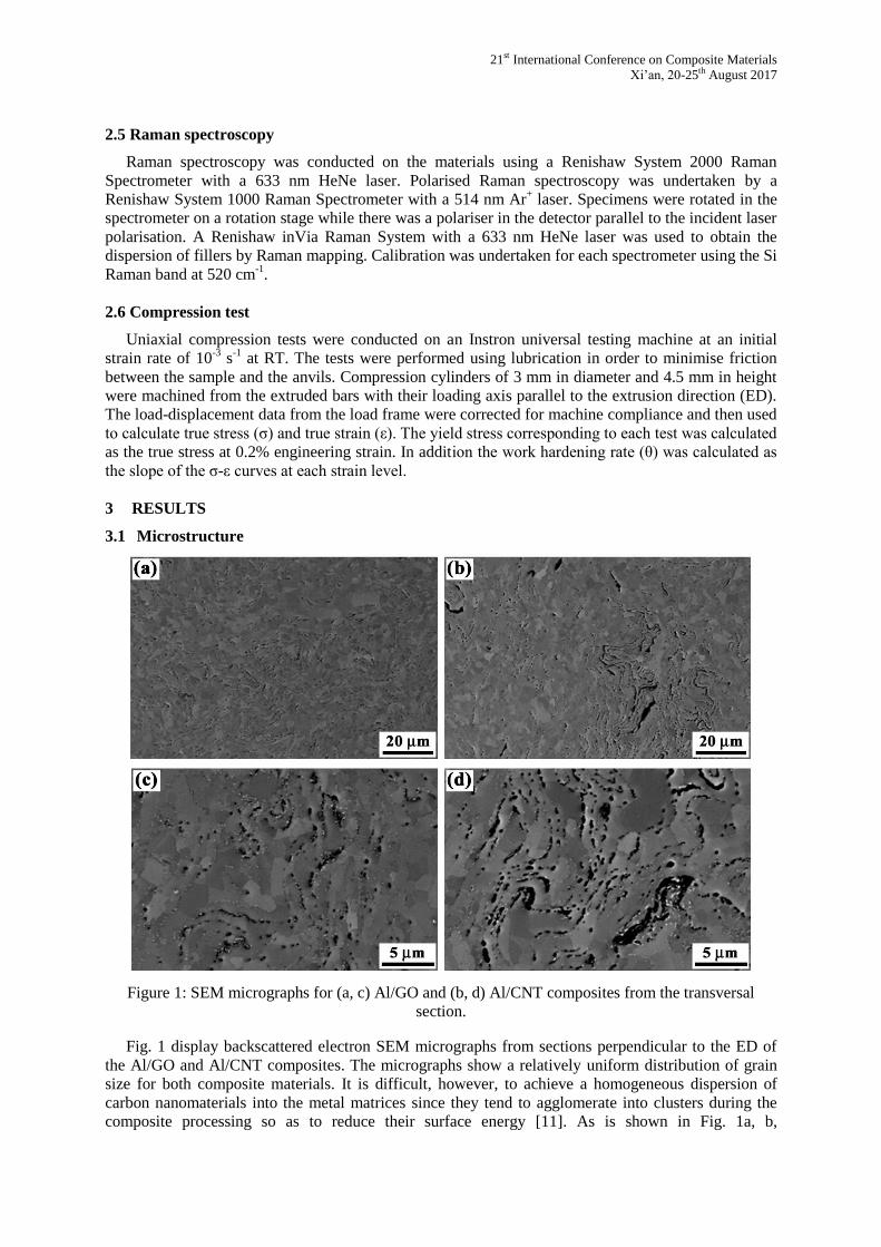
Figure 1: SEM micrographs for (a, c) Al/GO and (b, d) Al/CNT composites from the transversal
section.
Fig. 1 display backscattered electron SEM micrographs from sections perpendicular to the ED of
the Al/GO and Al/CNT composites. The micrographs show a relatively uniform distribution of grain
size for both composite materials. It is difficult, however, to achieve a homogeneous dispersion of
carbon nanomaterials into the metal matrices since they tend to agglomerate into clusters during the
composite processing so as to reduce their surface energy [11]. As is shown in Fig. 1a, b,
Fei Lin, Paloma Hidalgo-Manrique, Ian A. Kinloch, Robert J. Young
reinforcements are not uniformed dispersed in the Al matrix. Reinforcement clusters (in black
contrast) are clearly observed in both materials, and is more evident in the Al/CNT composite. These
clusters are preferentially located at the grain boundaries (GBs), in agreement with other references
[3,11,18–21].
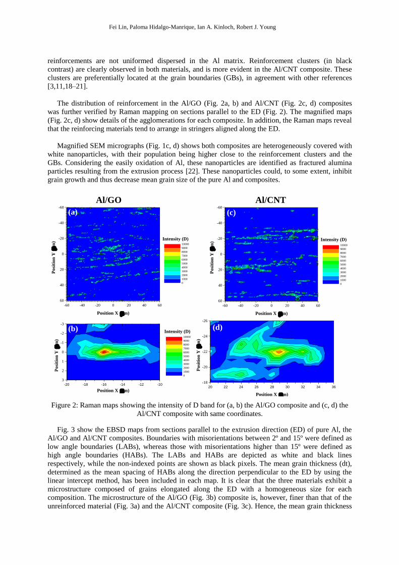
The distribution of reinforcement in the Al/GO (Fig. 2a, b) and Al/CNT (Fig. 2c, d) composites
was further verified by Raman mapping on sections parallel to the ED (Fig. 2). The magnified maps
(Fig. 2c, d) show details of the agglomerations for each composite. In addition, the Raman maps reveal
that the reinforcing materials tend to arrange in stringers aligned along the ED.
Magnified SEM micrographs (Fig. 1c, d) shows both composites are heterogeneously covered with
white nanoparticles, with their population being higher close to the reinforcement clusters and the
GBs. Considering the easily oxidation of Al, these nanoparticles are identified as fractured alumina
particles resulting from the extrusion process [22]. These nanoparticles could, to some extent, inhibit
grain growth and thus decrease mean grain size of the pure Al and composites.
Figure 2: Raman maps showing the intensity of D band for (a, b) the Al/GO composite and (c, d) the
Al/CNT composite with same coordinates.
Fig. 3 show the EBSD maps from sections parallel to the extrusion direction (ED) of pure Al, the
Al/GO and Al/CNT composites. Boundaries with misorientations between 2º and 15º were defined as
low angle boundaries (LABs), whereas those with misorientations higher than 15º were defined as
high angle boundaries (HABs). The LABs and HABs are depicted as white and black lines
respectively, while the non-indexed points are shown as black pixels. The mean grain thickness (dt),
determined as the mean spacing of HABs along the direction perpendicular to the ED by using the
linear intercept method, has been included in each map. It is clear that the three materials exhibit a
microstructure composed of grains elongated along the ED with a homogeneous size for each
composition. The microstructure of the Al/GO (Fig. 3b) composite is, however, finer than that of the
unreinforced material (Fig. 3a) and the Al/CNT composite (Fig. 3c). Hence, the mean grain thickness
-60 -40 -20 0 20 40 60
60
40
20
0
-20
-40
-60
Posi
tion
Y (
m)
Position X (m)
0
1000
2000
3000
4000
5000
6000
7000
8000
9000
10000
Intensity (D)
-20 -18 -16 -14 -12 -10
3
2
1
0
-1
-2
-3
Intensity (D)
Posi
tion
Y (
m)
Position X (m)
0
1000
2000
3000
4000
5000
6000
7000
8000
9000
10000
-60 -40 -20 0 20 40 60
60
40
20
0
-20
-40
-60P
osi
tion
Y (
m)
Position X (m)
0
1000
2000
3000
4000
5000
6000
7000
8000
9000
10000
Intensity (D)
20 22 24 26 28 30 32 34 36
-18
-20
-22
-24
-26
Po
siti
on
Y (
m)
Position X (m)
Al/GO Al/CNT
(a) (c)
(b) (d)
21st International Conference on Composite Materials
Xi’an, 20-25th August 2017
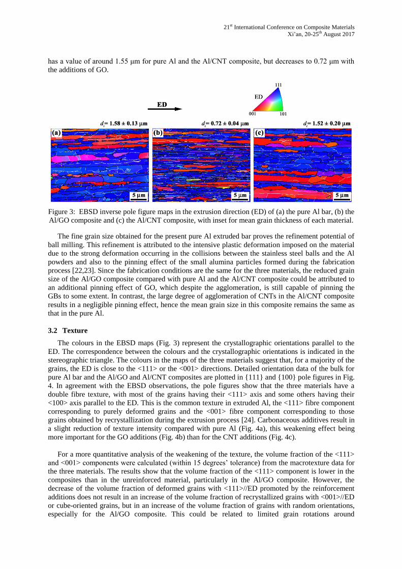
has a value of around 1.55 μm for pure Al and the Al/CNT composite, but decreases to 0.72 μm with
the additions of GO.
Figure 3: EBSD inverse pole figure maps in the extrusion direction (ED) of (a) the pure Al bar, (b) the
Al/GO composite and (c) the Al/CNT composite, with inset for mean grain thickness of each material.
The fine grain size obtained for the present pure Al extruded bar proves the refinement potential of
ball milling. This refinement is attributed to the intensive plastic deformation imposed on the material
due to the strong deformation occurring in the collisions between the stainless steel balls and the Al
powders and also to the pinning effect of the small alumina particles formed during the fabrication
process [22,23]. Since the fabrication conditions are the same for the three materials, the reduced grain
size of the Al/GO composite compared with pure Al and the Al/CNT composite could be attributed to
an additional pinning effect of GO, which despite the agglomeration, is still capable of pinning the
GBs to some extent. In contrast, the large degree of agglomeration of CNTs in the Al/CNT composite
results in a negligible pinning effect, hence the mean grain size in this composite remains the same as
that in the pure Al.
3.2 Texture
The colours in the EBSD maps (Fig. 3) represent the crystallographic orientations parallel to the
ED. The correspondence between the colours and the crystallographic orientations is indicated in the
stereographic triangle. The colours in the maps of the three materials suggest that, for a majority of the
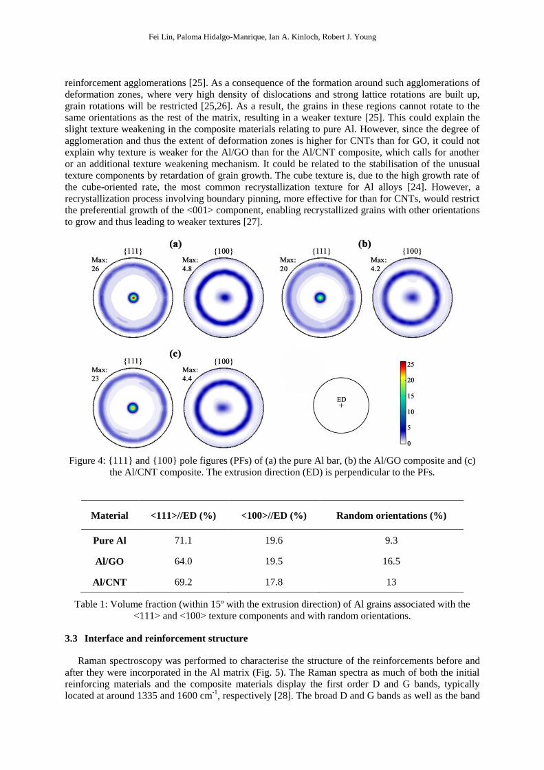
grains, the ED is close to the <111> or the <001> directions. Detailed orientation data of the bulk for
pure Al bar and the Al/GO and Al/CNT composites are plotted in {111} and {100} pole figures in Fig.
4. In agreement with the EBSD observations, the pole figures show that the three materials have a
double fibre texture, with most of the grains having their <111> axis and some others having their
<100> axis parallel to the ED. This is the common texture in extruded Al, the <111> fibre component
corresponding to purely deformed grains and the <001> fibre component corresponding to those
grains obtained by recrystallization during the extrusion process [24]. Carbonaceous additives result in
a slight reduction of texture intensity compared with pure Al (Fig. 4a), this weakening effect being
more important for the GO additions (Fig. 4b) than for the CNT additions (Fig. 4c).
For a more quantitative analysis of the weakening of the texture, the volume fraction of the <111>
and <001> components were calculated (within 15 degrees’ tolerance) from the macrotexture data for
the three materials. The results show that the volume fraction of the <111> component is lower in the
composites than in the unreinforced material, particularly in the Al/GO composite. However, the
decrease of the volume fraction of deformed grains with <111>//ED promoted by the reinforcement
additions does not result in an increase of the volume fraction of recrystallized grains with <001>//ED
or cube-oriented grains, but in an increase of the volume fraction of grains with random orientations,
especially for the Al/GO composite. This could be related to limited grain rotations around
Fei Lin, Paloma Hidalgo-Manrique, Ian A. Kinloch, Robert J. Young
reinforcement agglomerations [25]. As a consequence of the formation around such agglomerations of
deformation zones, where very high density of dislocations and strong lattice rotations are built up,
grain rotations will be restricted [25,26]. As a result, the grains in these regions cannot rotate to the
same orientations as the rest of the matrix, resulting in a weaker texture [25]. This could explain the
slight texture weakening in the composite materials relating to pure Al. However, since the degree of
agglomeration and thus the extent of deformation zones is higher for CNTs than for GO, it could not
explain why texture is weaker for the Al/GO than for the Al/CNT composite, which calls for another
or an additional texture weakening mechanism. It could be related to the stabilisation of the unusual
texture components by retardation of grain growth. The cube texture is, due to the high growth rate of
the cube-oriented rate, the most common recrystallization texture for Al alloys [24]. However, a
recrystallization process involving boundary pinning, more effective for than for CNTs, would restrict
the preferential growth of the <001> component, enabling recrystallized grains with other orientations
to grow and thus leading to weaker textures [27].
Figure 4: {111} and {100} pole figures (PFs) of (a) the pure Al bar, (b) the Al/GO composite and (c)
the Al/CNT composite. The extrusion direction (ED) is perpendicular to the PFs.
Material <111>//ED (%) <100>//ED (%) Random orientations (%)
Pure Al 71.1 19.6 9.3
Al/GO 64.0 19.5 16.5
Al/CNT 69.2 17.8 13
Table 1: Volume fraction (within 15º with the extrusion direction) of Al grains associated with the
<111> and <100> texture components and with random orientations.
3.3 Interface and reinforcement structure
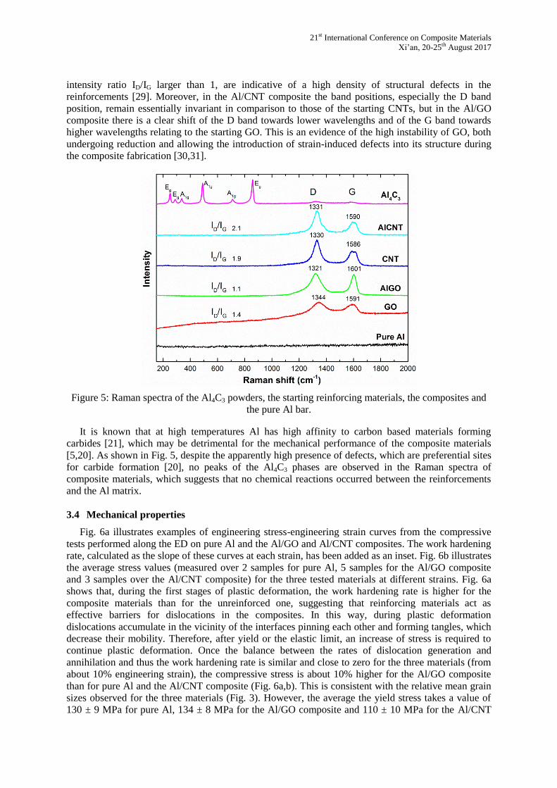
Raman spectroscopy was performed to characterise the structure of the reinforcements before and
after they were incorporated in the Al matrix (Fig. 5). The Raman spectra as much of both the initial
reinforcing materials and the composite materials display the first order D and G bands, typically
located at around 1335 and 1600 cm-1
, respectively [28]. The broad D and G bands as well as the band
21st International Conference on Composite Materials
Xi’an, 20-25th August 2017
intensity ratio ID/IG larger than 1, are indicative of a high density of structural defects in the
reinforcements [29]. Moreover, in the Al/CNT composite the band positions, especially the D band
position, remain essentially invariant in comparison to those of the starting CNTs, but in the Al/GO
composite there is a clear shift of the D band towards lower wavelengths and of the G band towards
higher wavelengths relating to the starting GO. This is an evidence of the high instability of GO, both
undergoing reduction and allowing the introduction of strain-induced defects into its structure during
the composite fabrication [30,31].
Figure 5: Raman spectra of the Al4C3 powders, the starting reinforcing materials, the composites and
the pure Al bar.
It is known that at high temperatures Al has high affinity to carbon based materials forming
carbides [21], which may be detrimental for the mechanical performance of the composite materials
[5,20]. As shown in Fig. 5, despite the apparently high presence of defects, which are preferential sites
for carbide formation [20], no peaks of the Al4C3 phases are observed in the Raman spectra of
composite materials, which suggests that no chemical reactions occurred between the reinforcements
and the Al matrix.
3.4 Mechanical properties
Fig. 6a illustrates examples of engineering stress-engineering strain curves from the compressive
tests performed along the ED on pure Al and the Al/GO and Al/CNT composites. The work hardening
rate, calculated as the slope of these curves at each strain, has been added as an inset. Fig. 6b illustrates
the average stress values (measured over 2 samples for pure Al, 5 samples for the Al/GO composite
and 3 samples over the Al/CNT composite) for the three tested materials at different strains. Fig. 6a
shows that, during the first stages of plastic deformation, the work hardening rate is higher for the
composite materials than for the unreinforced one, suggesting that reinforcing materials act as
effective barriers for dislocations in the composites. In this way, during plastic deformation
dislocations accumulate in the vicinity of the interfaces pinning each other and forming tangles, which
decrease their mobility. Therefore, after yield or the elastic limit, an increase of stress is required to
continue plastic deformation. Once the balance between the rates of dislocation generation and
annihilation and thus the work hardening rate is similar and close to zero for the three materials (from
about 10% engineering strain), the compressive stress is about 10% higher for the Al/GO composite
than for pure Al and the Al/CNT composite (Fig. 6a,b). This is consistent with the relative mean grain
sizes observed for the three materials (Fig. 3). However, the average the yield stress takes a value of
130 ± 9 MPa for pure Al, 134 ± 8 MPa for the Al/GO composite and 110 ± 10 MPa for the Al/CNT
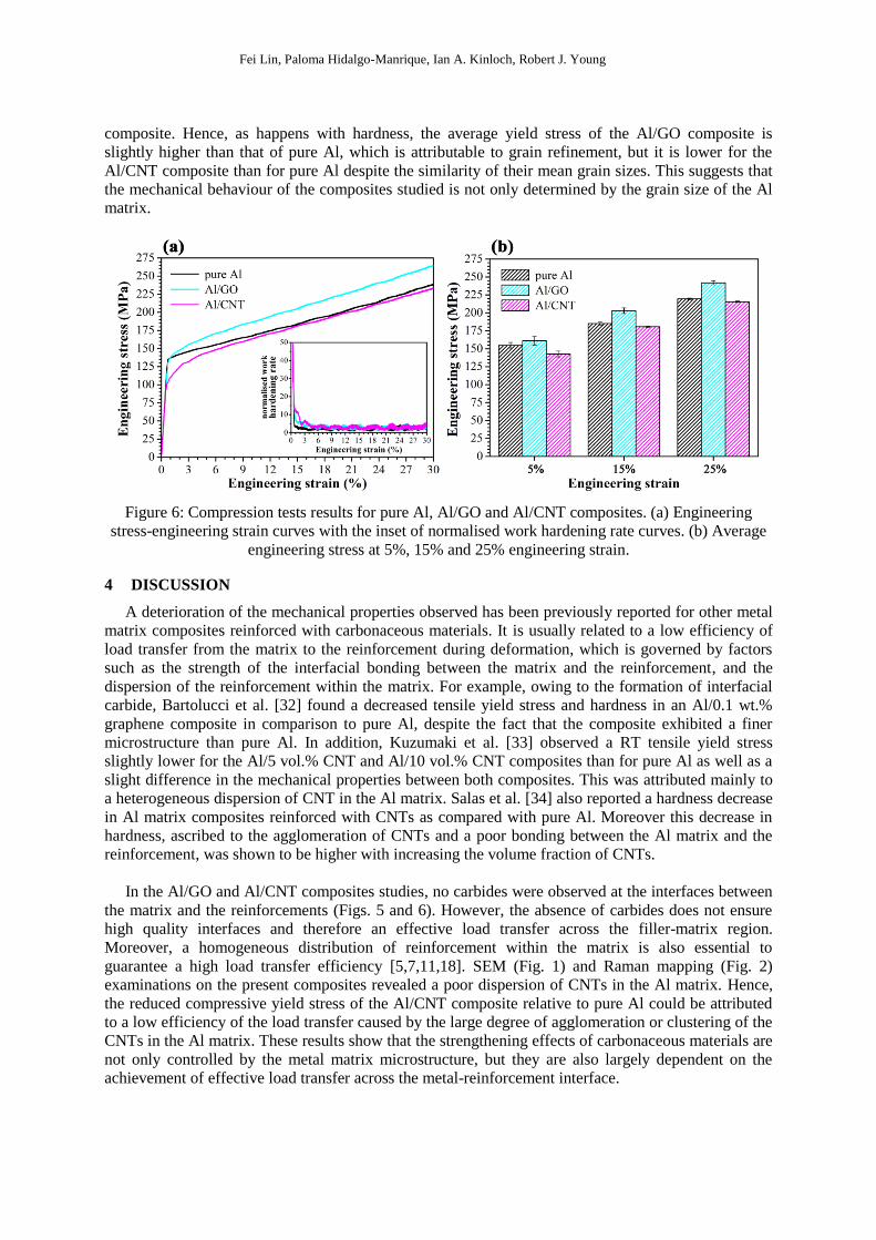
Fei Lin, Paloma Hidalgo-Manrique, Ian A. Kinloch, Robert J. Young
composite. Hence, as happens with hardness, the average yield stress of the Al/GO composite is
slightly higher than that of pure Al, which is attributable to grain refinement, but it is lower for the
Al/CNT composite than for pure Al despite the similarity of their mean grain sizes. This suggests that
the mechanical behaviour of the composites studied is not only determined by the grain size of the Al
matrix.
Figure 6: Compression tests results for pure Al, Al/GO and Al/CNT composites. (a) Engineering
stress-engineering strain curves with the inset of normalised work hardening rate curves. (b) Average
engineering stress at 5%, 15% and 25% engineering strain.
4 DISCUSSION
A deterioration of the mechanical properties observed has been previously reported for other metal
matrix composites reinforced with carbonaceous materials. It is usually related to a low efficiency of
load transfer from the matrix to the reinforcement during deformation, which is governed by factors
such as the strength of the interfacial bonding between the matrix and the reinforcement, and the
dispersion of the reinforcement within the matrix. For example, owing to the formation of interfacial
carbide, Bartolucci et al. [32] found a decreased tensile yield stress and hardness in an Al/0.1 wt.%
graphene composite in comparison to pure Al, despite the fact that the composite exhibited a finer
microstructure than pure Al. In addition, Kuzumaki et al. [33] observed a RT tensile yield stress
slightly lower for the Al/5 vol.% CNT and Al/10 vol.% CNT composites than for pure Al as well as a
slight difference in the mechanical properties between both composites. This was attributed mainly to
a heterogeneous dispersion of CNT in the Al matrix. Salas et al. [34] also reported a hardness decrease
in Al matrix composites reinforced with CNTs as compared with pure Al. Moreover this decrease in
hardness, ascribed to the agglomeration of CNTs and a poor bonding between the Al matrix and the
reinforcement, was shown to be higher with increasing the volume fraction of CNTs.
In the Al/GO and Al/CNT composites studies, no carbides were observed at the interfaces between
the matrix and the reinforcements (Figs. 5 and 6). However, the absence of carbides does not ensure
high quality interfaces and therefore an effective load transfer across the filler-matrix region.
Moreover, a homogeneous distribution of reinforcement within the matrix is also essential to
guarantee a high load transfer efficiency [5,7,11,18]. SEM (Fig. 1) and Raman mapping (Fig. 2)
examinations on the present composites revealed a poor dispersion of CNTs in the Al matrix. Hence,
the reduced compressive yield stress of the Al/CNT composite relative to pure Al could be attributed
to a low efficiency of the load transfer caused by the large degree of agglomeration or clustering of the
CNTs in the Al matrix. These results show that the strengthening effects of carbonaceous materials are
not only controlled by the metal matrix microstructure, but they are also largely dependent on the
achievement of effective load transfer across the metal-reinforcement interface.
21st International Conference on Composite Materials
Xi’an, 20-25th August 2017
5 CONCLUSIONS
Al matrix composites were reinforced with 0.5 wt. % GO and 0.5 wt. % CNTs by PM. We
analysed the microstructure, texture, and mechanical behaviour of the composites compared with pure
Al, and the reinforcement structure, as well as the interfacial reaction.
1. Both reinforcing materials tend to disperse heterogeneously in the Al matrix, resulting in the
formation of agglomerates at the GBs. However, the extent of clustering is higher in the Al/CNT
composite than in the Al/GO composite.
2. The pure Al bar as well as the composite materials exhibit a microstructure composed of
grains elongated along the ED. However, while the Al/CNT composite exhibits the same mean grain
size as the unreinforced material, the Al/GO composite exhibits a more refined microstructure due to
the pinning effect of GO.
3. The texture of the unreinforced material and the composites consists mainly of the double
<111> + <100> fibre, typical of extruded Al bars. Compared with pure Al, the intensity of this
extrusion texture decreases with the addition of both carbonaceous materials, attributable to the
formation of deformation zones around the reinforcement agglomerations. In addition, the pinning of
GBs can be considered to restrict the preferential growth of certain orientations, leading to further
texture weakening in the Al/GO composite.
4. The composite fabrication process introduces structural defects in the reinforcing materials,
but no carbide formation was observed at interfaces between the Al matrix and the reinforcements.
5. In agreement with their relative mean grain sizes, the Al/GO composite shows improved
mechanical properties over pure Al. However, despite the similarity of the mean grain sizes, the
Al/CNT composite displays decreased compressive yield stress relative to pure Al. This was ascribed
to a low efficiency of load transfer from the Al matrix to the CNTs resulting from agglomeration.
ACKNOWLEDGEMENTS
The authors would like to appreciate the financial support from Beijing Institute for Aeronautical
Materials (BIAM) within The Aviation Industry Corporation of China (AVIC).
REFERENCES
[1] E.A. Starke, J.T. Staley, Application of modern aluminum alloys to aircraft, Prog. Aerosp. Sci.
32 (1996) 131–172. doi:10.1016/0376-0421(95)00004-6.
[2] J.C. Williams, E.A. Starke, Progress in structural materials for aerospace systems, Acta Mater.
51 (2003) 5775–5799. doi:10.1016/j.actamat.2003.08.023.
[3] W. Miller, L. Zhuang, J. Bottema, A. Wittebrood, P. De Smet, A. Haszler, A. Vieregge, Recent
development in aluminium alloys for the automotive industry, Mater. Sci. Eng. A. 280 (2000)
37–49. doi:10.1016/S0921-5093(99)00653-X.
[4] J. Li, Y. Xiong, X.D. Wang, S.J. Yan, C. Yang, W. He, J. Chen, S. Wang, X. Zhang, S. Dai,
Microstructure and tensile properties of bulk nanostructured aluminum/graphene composites
prepared via cryomilling, Mater. Sci. Eng. A. 626 (2015) 400–405.
doi:10.1016/j.msea.2014.12.102.
[5] I.A. Ibrahim, F.A. Mohamed, E.J. Lavernia, Particulate reinforced metal matrix composites - a
review, J. Mater. Sci. 26 (1991) 1137–1156. doi:10.1007/BF00544448.
[6] D. Miracle, Metal matrix composites – From science to technological significance, Compos.
Sci. Technol. 65 (2005) 2526–2540. doi:10.1016/j.compscitech.2005.05.027.
[7] A. Mortensen, J. Llorca, Metal Matrix Composites, Annu. Rev. Mater. Res. 40 (2010) 243–
270. doi:10.1146/annurev-matsci-070909-104511.
Fei Lin, Paloma Hidalgo-Manrique, Ian A. Kinloch, Robert J. Young
[8] R.O. Ritchie, The conflicts between strength and toughness, Nat. Mater. 10 (2011) 817–822.
doi:10.1038/nmat3115.
[9] S.T. Mavhungu, E.T. Akinlabi, M.A. Onitiri, F.M. Varachia, Aluminum Matrix Composites for
Industrial Use: Advances and Trends, Procedia Manuf. 7 (2017) 178–182.
doi:10.1016/j.promfg.2016.12.045.
[10] S.J. Yan, S.L. Dai, X.Y. Zhang, C. Yang, Q.H. Hong, J.Z. Chen, Z.M. Lin, Investigating
aluminum alloy reinforced by graphene nanoflakes, Mater. Sci. Eng. A. 612 (2014) 440–444.
doi:10.1016/j.msea.2014.06.077.
[11] S.C. Tjong, Recent progress in the development and properties of novel metal matrix
nanocomposites reinforced with carbon nanotubes and graphene nanosheets, Mater. Sci. Eng. R
Reports. 74 (2013) 281–350. doi:10.1016/j.mser.2013.08.001.
[12] S. Stankovich, D.A. Dikin, G.H.B. Dommett, K.M. Kohlhaas, E.J. Zimney, E.A. Stach, R.D.
Piner, S.T. Nguyen, R.S. Ruoff, Graphene-based composite materials, Nature. 442 (2006) 282–
286. doi:10.1038/nature04969.
[13] J.R. Potts, D.R. Dreyer, C.W. Bielawski, R.S. Ruoff, Graphene-based polymer
nanocomposites, Polymer (Guildf). 52 (2011) 5–25. doi:10.1016/j.polymer.2010.11.042.
[14] R.J. Young, I. A. Kinloch, L. Gong, K.S. Novoselov, The mechanics of graphene
nanocomposites: A review, Compos. Sci. Technol. 72 (2012) 1459–1476.
doi:10.1016/j.compscitech.2012.05.005.
[15] J.N. Coleman, U. Khan, W.J. Blau, Y.K. Gun’ko, Small but strong: A review of the mechanical
properties of carbon nanotube–polymer composites, Carbon N. Y. 44 (2006) 1624–1652.
doi:10.1016/j.carbon.2006.02.038.
[16] E.T. Thostenson, Z. Ren, T.-W. Chou, Advances in the science and technology of carbon
nanotubes and their composites: a review, Compos. Sci. Technol. 61 (2001) 1899–1912.
doi:10.1016/S0266-3538(01)00094-X.
[17] C. A. Cooper, R.J. Young, M. Halsall, Investigation into the deformation of carbon nanotubes
and their composites through the use of Raman spectroscopy, Compos. Part A Appl. Sci.
Manuf. 32 (2001) 401–411. doi:10.1016/S1359-835X(00)00107-X.
[18] S.R. Bakshi, D. Lahiri, A. Agarwal, Carbon nanotube reinforced metal matrix composites - a
review, Int. Mater. Rev. 55 (2010) 41–64. doi:10.1179/095066009X12572530170543.
[19] D.B. Xiong, M. Cao, Q. Guo, Z. Tan, G. Fan, Z. Li, D. Zhang, Graphene-and-Copper Artificial
Nacre Fabricated by a Preform Impregnation Process: Bioinspired Strategy for Strengthening-
Toughening of Metal Matrix Composite, ACS Nano. 9 (2015) 6934–6943.
doi:10.1021/acsnano.5b01067.
[20] W. Zhou, T. Yamaguchi, K. Kikuchi, N. Nomura, A. Kawasaki, Effectively enhanced load
transfer by interfacial reactions in multi-walled carbon nanotube reinforced Al matrix
composites, Acta Mater. 125 (2017) 369–376. doi:10.1016/j.actamat.2016.12.022.
[21] A. El-Ghazaly, G. Anis, H.G. Salem, Effect of graphene addition on the mechanical and
tribological behavior of nanostructured AA2124 self-lubricating metal matrix composite,
Compos. Part A Appl. Sci. Manuf. 95 (2017) 325–336. doi:10.1016/j.compositesa.2017.02.006.
[22] J. Corrochano, P. Hidalgo, M. Lieblich, J. Ibáñez, Matrix grain characterisation by electron
backscattering diffraction of powder metallurgy aluminum matrix composites reinforced with
MoSi2 intermetallic particles, Mater. Charact. 61 (2010) 1294–1298.
doi:10.1016/j.matchar.2010.08.010.
[23] J. Corrochano, J.C. Walker, M. Lieblich, J. Ibáñez, W.M. Rainforth, Dry sliding wear
behaviour of powder metallurgy Al–Mg–Si alloy-MoSi2 composites and the relationship with
the microstructure, Wear. 270 (2011) 658–665. doi:10.1016/j.wear.2011.01.029.
[24] I.L. Dillamore, W.T. Roberts, Preferred orientation in wrought and annealed metals, Metall.
Rev. 10 (1965) 271–380. doi:10.1179/mtlr.1965.10.1.271.
[25] X. Jiang, M. Galano, F. Audebert, Extrusion textures in Al, 6061 alloy and 6061/SiCp
21st International Conference on Composite Materials
Xi’an, 20-25th August 2017
nanocomposites, Mater. Charact. 88 (2014) 111–118. doi:10.1016/j.matchar.2013.11.009.
[26] F.J. Humphreys, P.N. Kalu, The plasticity of particle-containing polycrystals, Acta Metall.
Mater. 38 (1990) 917–930. doi:10.1016/0956-7151(90)90164-C.
[27] P. Hidalgo-Manrique, S.B. Yi, J. Bohlen, D. Letzig, M.T. Pérez-Prado, Effect of Nd Additions
on Extrusion Texture Development and on Slip Activity in a Mg-Mn Alloy, Metall. Mater.
Trans. A. 44 (2013) 4819–4829. doi:10.1007/s11661-013-1823-7.
[28] D.G. Papageorgiou, I.A. Kinloch, R.J. Young, Graphene/elastomer nanocomposites, Carbon N.
Y. 95 (2015) 460–484. doi:10.1016/j.carbon.2015.08.055.
[29] A.C. Ferrari, D.M. Basko, Raman spectroscopy as a versatile tool for studying the properties of
graphene, Nat. Nanotechnol. 8 (2013) 235–246. doi:DOI 10.1038/nnano.2013.46.
[30] Z. Li, R.J. Young, I. A Kinloch, Interfacial Stress Transfer in Graphene Oxide
Nanocomposites, ACS Appl. Mater. Interfaces. 5 (2013) 456–463. doi:10.1021/am302581e.
[31] D. Poirier, R. Gauvin, R.A.L. Drew, Structural characterization of a mechanically milled
carbon nanotube/aluminum mixture, Compos. Part A Appl. Sci. Manuf. 40 (2009) 1482–1489.
doi:10.1016/j.compositesa.2009.05.025.
[32] S.F. Bartolucci, J. Paras, M.A. Rafiee, J. Rafiee, S. Lee, D. Kapoor, N. Koratkar, Graphene–
aluminum nanocomposites, Mater. Sci. Eng. A. 528 (2011) 7933–7937.
doi:10.1016/j.msea.2011.07.043.
[33] T. Kuzumaki, K. Miyazawa, H. Ichinose, K. Ito, Processing of Carbon Nanotube Reinforced
Aluminum Composite, J. Mater. Res. 13 (1998) 2445–2449. doi:10.1557/JMR.1998.0340.
[34] W. Salas, N.G. Alba-Baena, L.E. Murr, Explosive Shock-Wave Consolidation of Aluminum
Powder/Carbon Nanotube Aggregate Mixtures: Optical and Electron Metallography, Metall.
Mater. Trans. A. 38 (2007) 2928–2935. doi:10.1007/s11661-007-9336-x.