LISA Gravitational Reference Sensors - icecube.wisc.edu · for GRS Gap Measurement Optical Fiber...
44
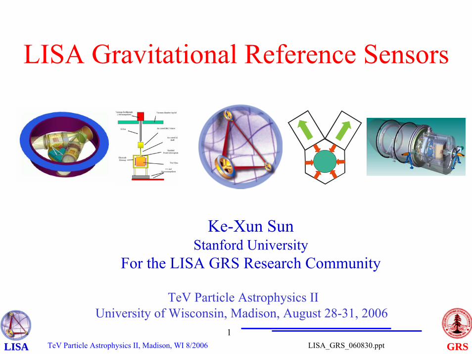
TeV Particle Astrophysics II, Madison, WI 8/2006 1 GRS LISA_GRS_060830.ppt LISA LISA LISA Gravitational Reference Sensors TeV Particle Astrophysics II University of Wisconsin, Madison, August 28-31, 2006 Ke-Xun Sun Stanford University For the LISA GRS Research Community
Transcript of LISA Gravitational Reference Sensors - icecube.wisc.edu · for GRS Gap Measurement Optical Fiber...
TeV Particle Astrophysics II, Madison, WI 8/20061
GRSLISA_GRS_060830.pptLISALISA
LISA Gravitational Reference Sensors
TeV Particle Astrophysics IIUniversity of Wisconsin, Madison, August 28-31, 2006
Ke-Xun SunStanford University
For the LISA GRS Research Community
TeV Particle Astrophysics II, Madison, WI 8/20062
GRSLISA_GRS_060830.pptLISALISA
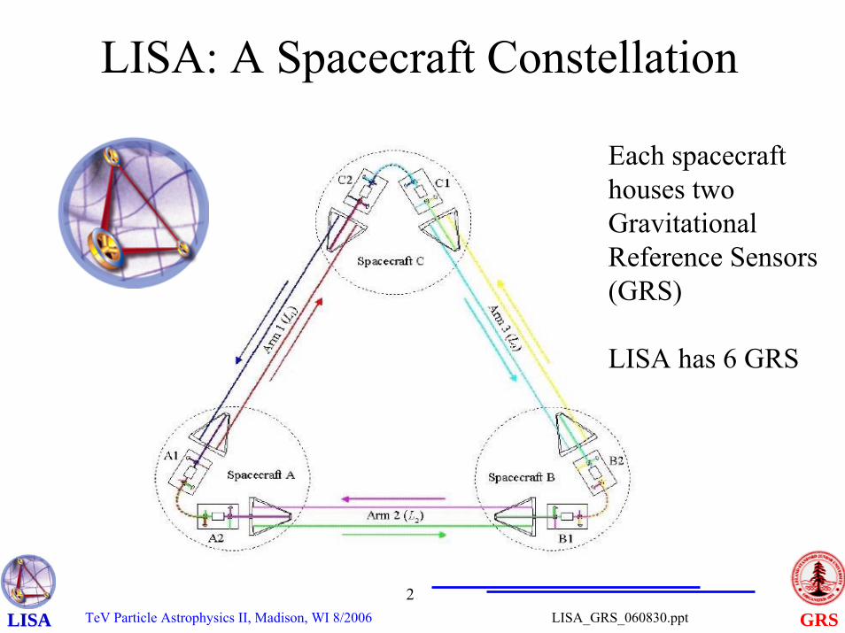
LISA: A Spacecraft Constellation
Each spacecraft houses two Gravitational Reference Sensors (GRS)
LISA has 6 GRS
TeV Particle Astrophysics II, Madison, WI 8/20063
GRSLISA_GRS_060830.pptLISALISA
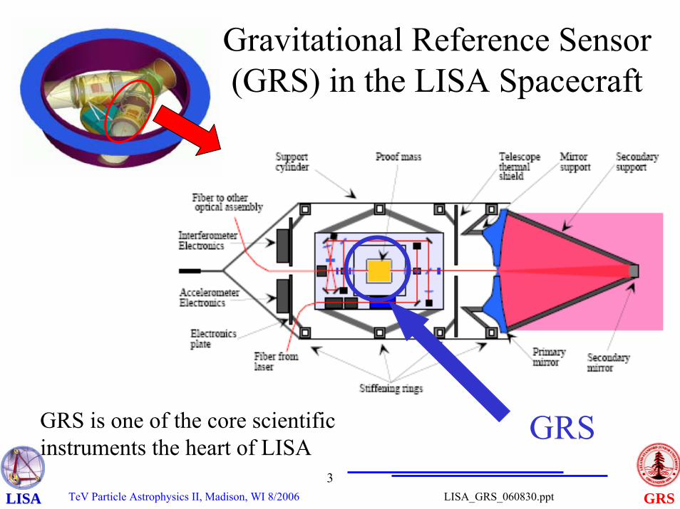
GRS
Gravitational Reference Sensor (GRS) in the LISA Spacecraft
GRS is one of the core scientificinstruments the heart of LISA
TeV Particle Astrophysics II, Madison, WI 8/20064
GRSLISA_GRS_060830.pptLISALISA
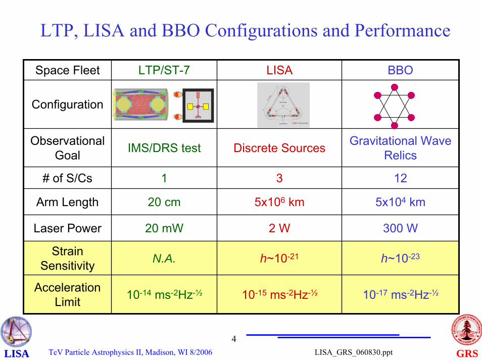
LTP, LISA and BBO Configurations and Performance
Space Fleet LTP/ST-7 LISA BBO
Configuration
IMS/DRS test
1
20 cm
20 mW
N.A.
10-14 ms-2Hz-½
Observational Goal Discrete Sources Gravitational Wave
Relics
# of S/Cs 3 12
Arm Length 5x10⁶ km 5x10⁴ km
Laser Power 2 W 300 W
Strain Sensitivity h~10-21 h~10-23
Acceleration Limit 10-15 ms-2Hz-½ 10-17 ms-2Hz-½
TeV Particle Astrophysics II, Madison, WI 8/20065
GRSLISA_GRS_060830.pptLISALISA
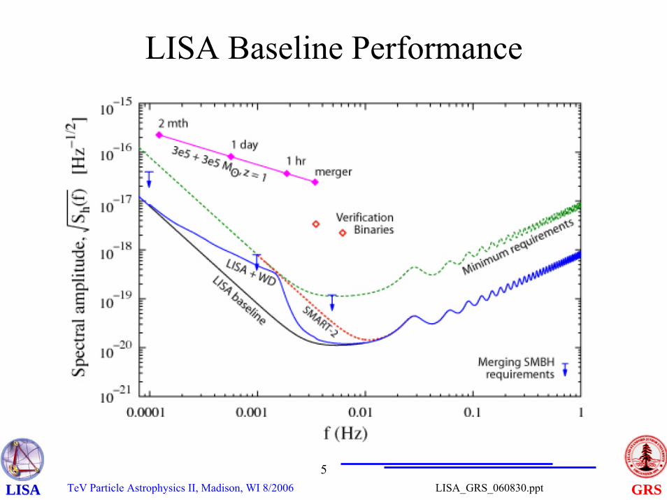
LISA Baseline Performance
TeV Particle Astrophysics II, Madison, WI 8/20066
GRSLISA_GRS_060830.pptLISALISA
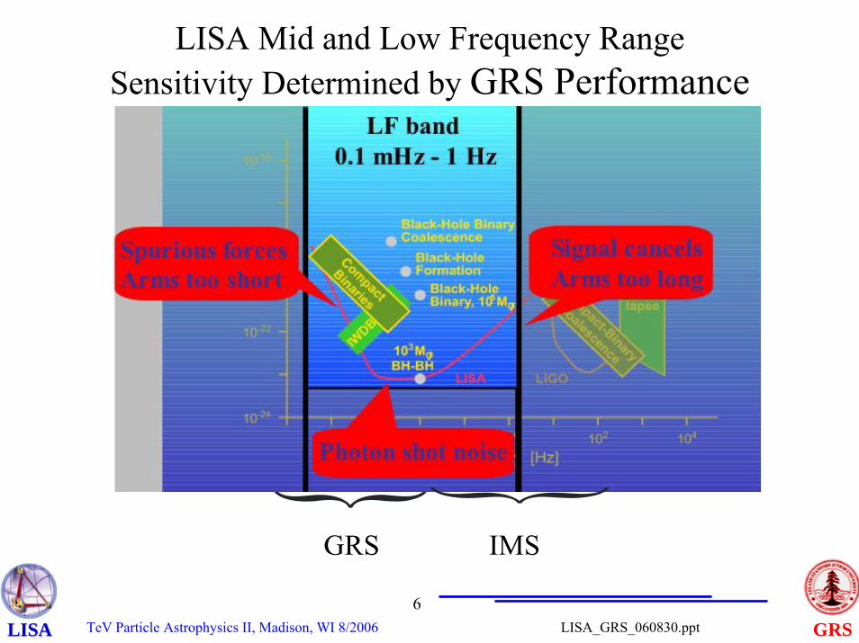
LISA Mid and Low Frequency RangeSensitivity Determined by GRS Performance
GRS
}IMS
TeV Particle Astrophysics II, Madison, WI 8/20067
GRSLISA_GRS_060830.pptLISALISA
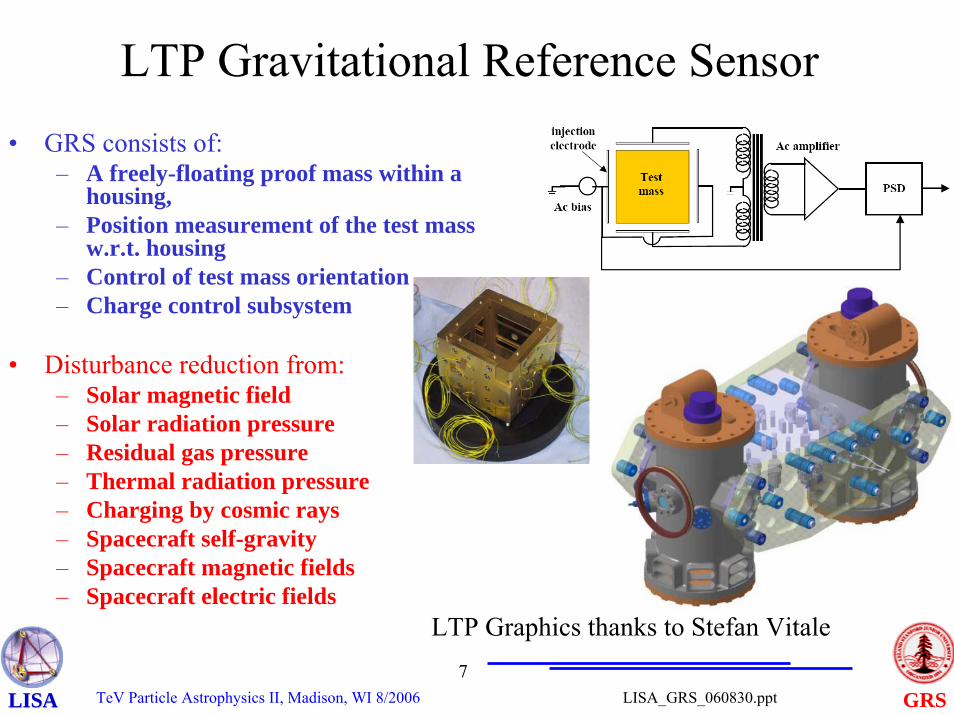
• GRS consists of:– A freely-floating proof mass within a
housing,– Position measurement of the test mass
w.r.t. housing– Control of test mass orientation– Charge control subsystem
• Disturbance reduction from:– Solar magnetic field– Solar radiation pressure– Residual gas pressure– Thermal radiation pressure– Charging by cosmic rays– Spacecraft self-gravity– Spacecraft magnetic fields– Spacecraft electric fields
LTP Gravitational Reference Sensor
LTP Graphics thanks to Stefan Vitale
TeV Particle Astrophysics II, Madison, WI 8/20068
GRSLISA_GRS_060830.pptLISALISA
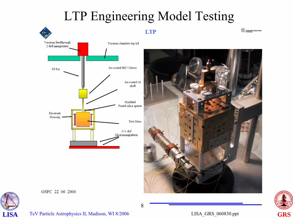
LTP Engineering Model Testing
TeV Particle Astrophysics II, Madison, WI 8/20069
GRSLISA_GRS_060830.pptLISALISA
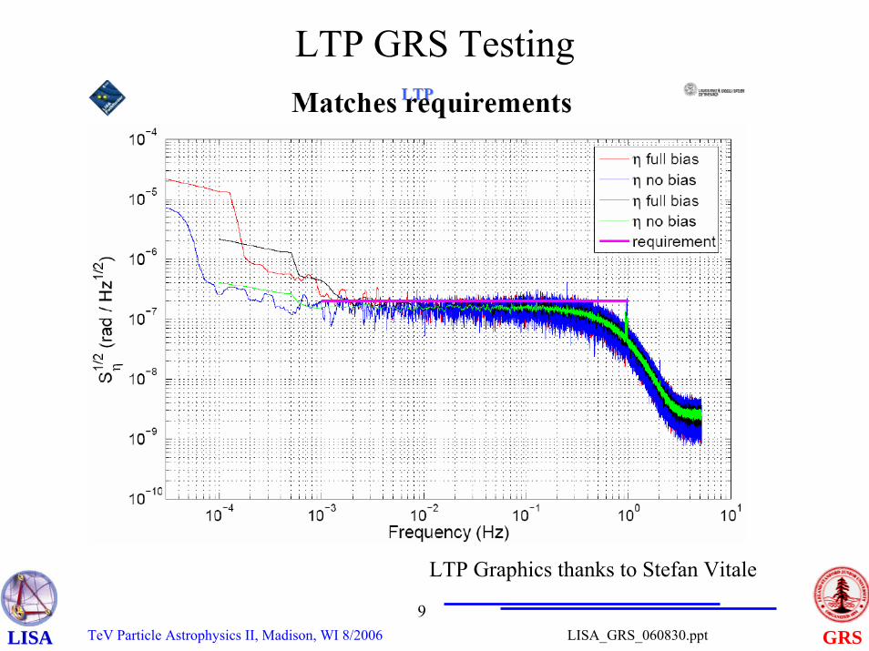
LTP GRS Testing
LTP Graphics thanks to Stefan Vitale
TeV Particle Astrophysics II, Madison, WI 8/200610
GRSLISA_GRS_060830.pptLISALISA
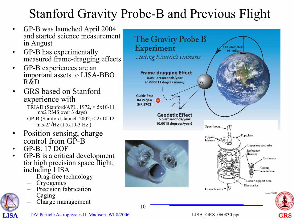
Stanford Gravity Probe-B and Previous Flight• GP-B was launched April 2004
and started science measurement in August
• GP-B has experimentally measured frame-dragging effects
• GP-B experiences are an important assets to LISA-BBO R&D
• GRS based on Stanford experience with
TRIAD (Stanford/APL, 1972, < 5x10-11 m/s2 RMS over 3 days)
GP-B (Stanford, launch 2002, < 2x10-12 m.s-2/√Hz at 5x10⁻³ Hz )
• Position sensing, charge control from GP-B
• GP-B: 17 DOF• GP-B is a critical development
for high precision space flight, including LISA
– Drag-free technology– Cryogenics– Precision fabrication– Caging– Charge management
TeV Particle Astrophysics II, Madison, WI 8/200611
GRSLISA_GRS_060830.pptLISALISA
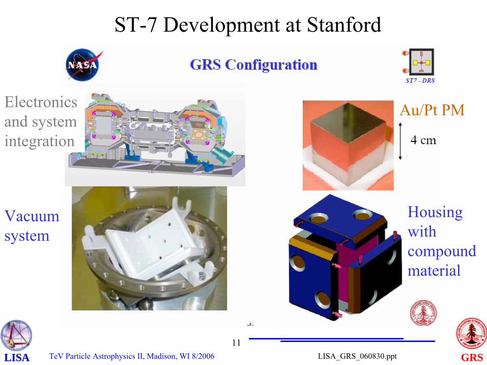
ST-7 Development at Stanford
Au/Pt PM
Housing with compound material
Vacuum system
Electronics and system integration
TeV Particle Astrophysics II, Madison, WI 8/200612
GRSLISA_GRS_060830.pptLISALISA
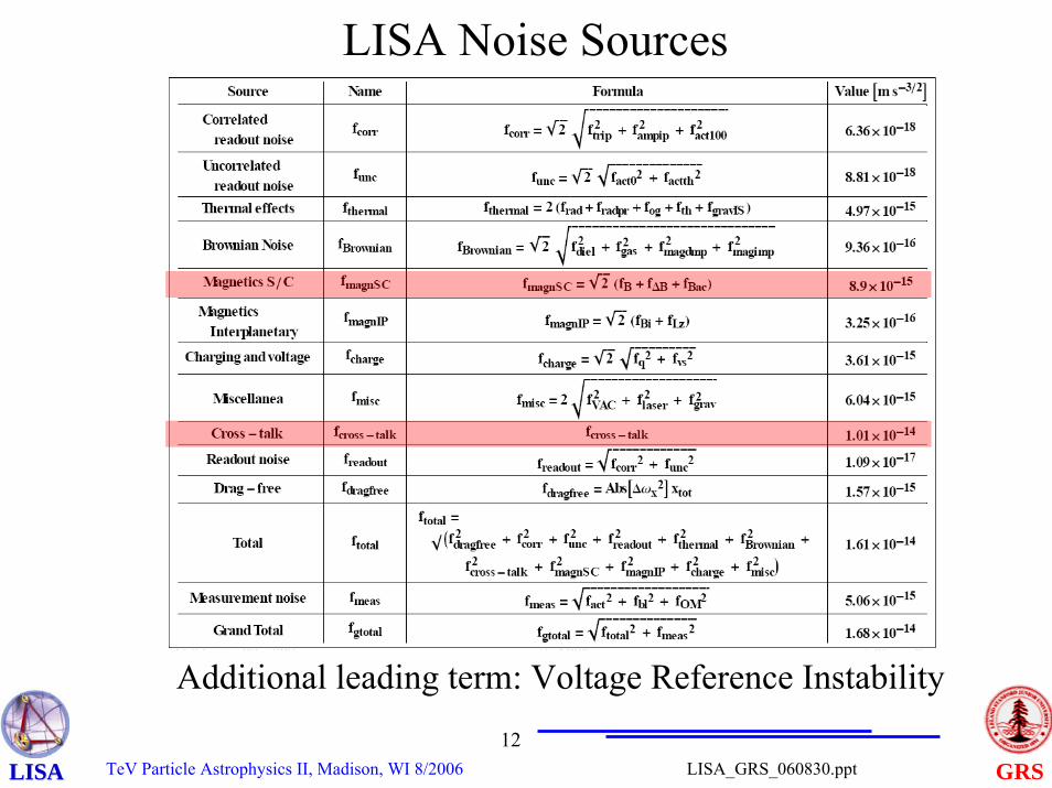
LISA Noise Sources
Additional leading term: Voltage Reference Instability
TeV Particle Astrophysics II, Madison, WI 8/200613
GRSLISA_GRS_060830.pptLISALISA
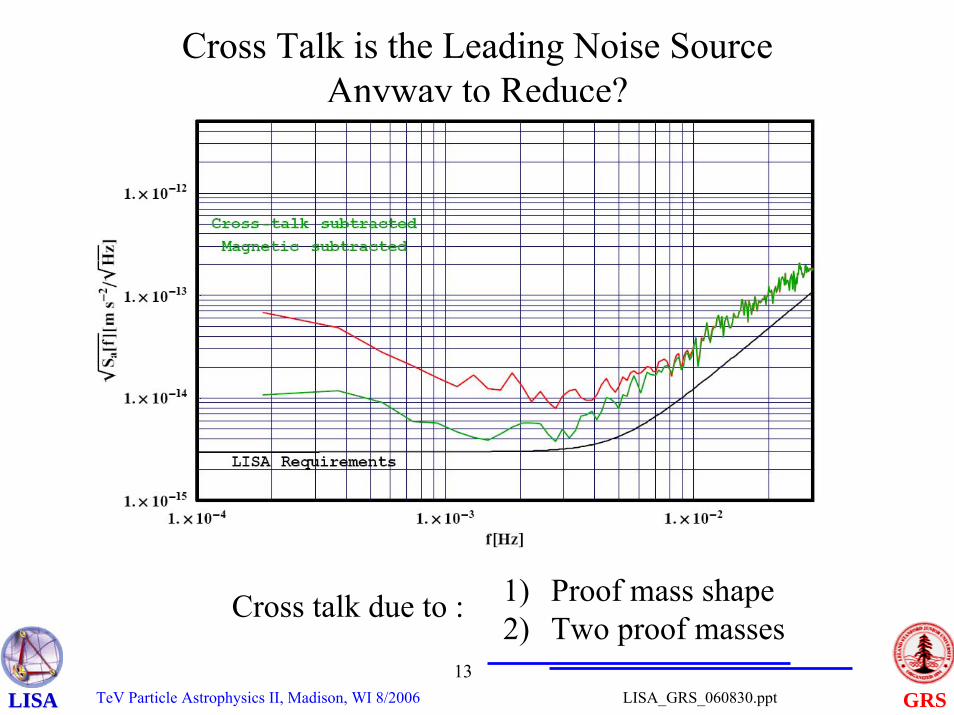
Cross Talk is the Leading Noise SourceAnyway to Reduce?
Cross talk due to : 1) Proof mass shape2) Two proof masses
TeV Particle Astrophysics II, Madison, WI 8/200614
GRSLISA_GRS_060830.pptLISALISA
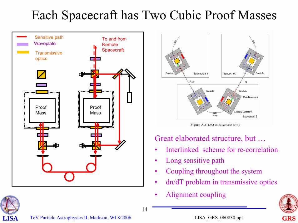
Each Spacecraft has Two Cubic Proof Masses
Proof Mass
ProofMass
To and from Remote Spacecraft
Waveplate
Transmissive optics
Sensitive path
Great elaborated structure, but …• Interlinked scheme for re-correlation• Long sensitive path• Coupling throughout the system• dn/dT problem in transmissive optics
• Alignment coupling
TeV Particle Astrophysics II, Madison, WI 8/200615
GRSLISA_GRS_060830.pptLISALISA
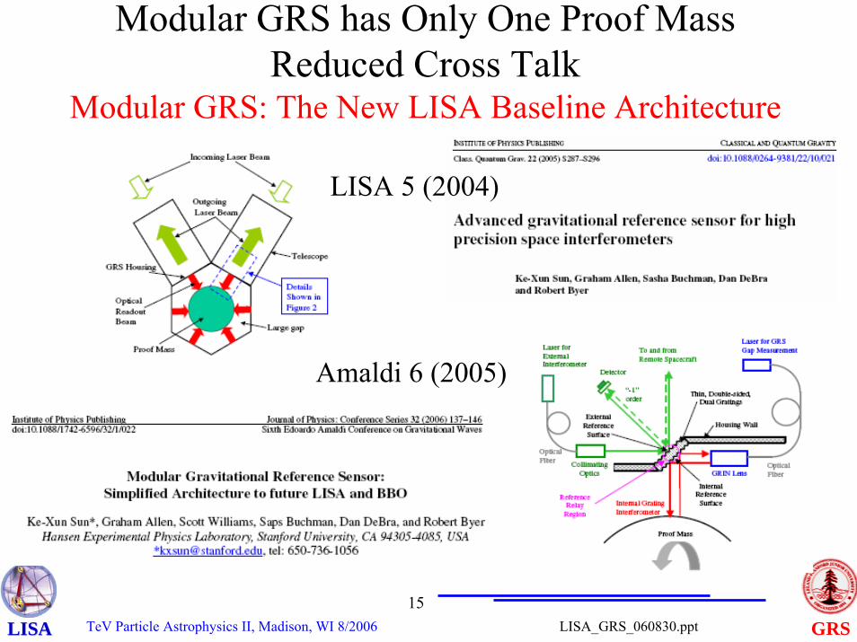
Modular GRS has Only One Proof MassReduced Cross Talk
Modular GRS: The New LISA Baseline Architecture
LISA 5 (2004)
Amaldi 6 (2005)
TeV Particle Astrophysics II, Madison, WI 8/200616
GRSLISA_GRS_060830.pptLISALISA
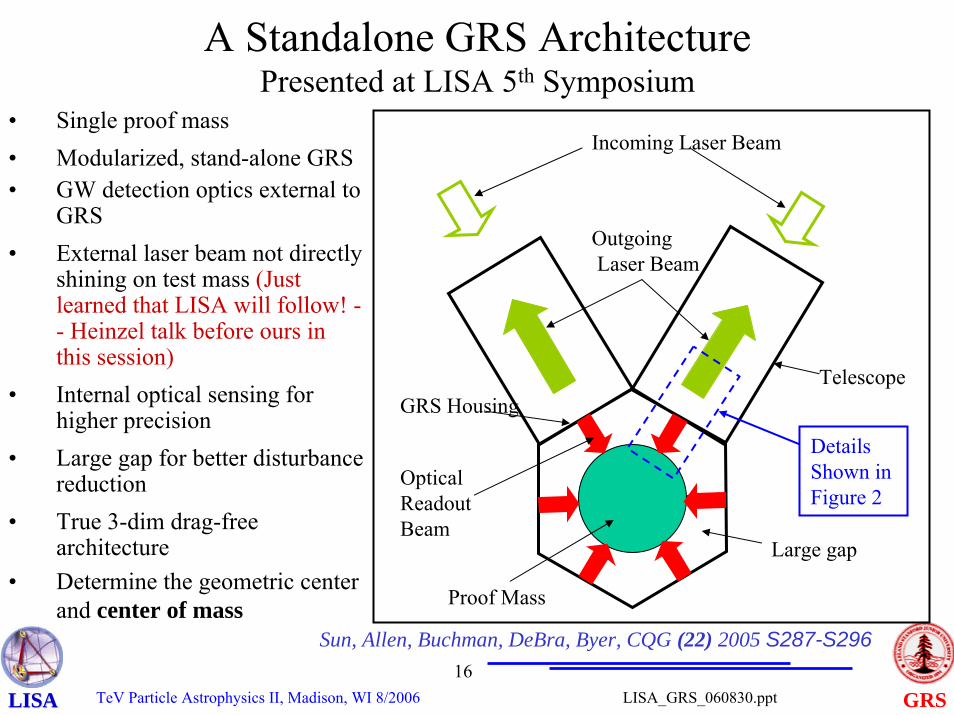
A Standalone GRS Architecture Presented at LISA 5th Symposium
OutgoingLaser Beam
Proof Mass
Large gap
GRS Housing
Optical ReadoutBeam
Telescope
Incoming Laser Beam
Details Shown in Figure 2
• Single proof mass• Modularized, stand-alone GRS• GW detection optics external to
GRS• External laser beam not directly
shining on test mass (Just learned that LISA will follow! -- Heinzel talk before ours in this session)
• Internal optical sensing for higher precision
• Large gap for better disturbance reduction
• True 3-dim drag-free architecture
• Determine the geometric center and center of mass
Sun, Allen, Buchman, DeBra, Byer, CQG (22) 2005 S287-S296
TeV Particle Astrophysics II, Madison, WI 8/200617
GRSLISA_GRS_060830.pptLISALISA
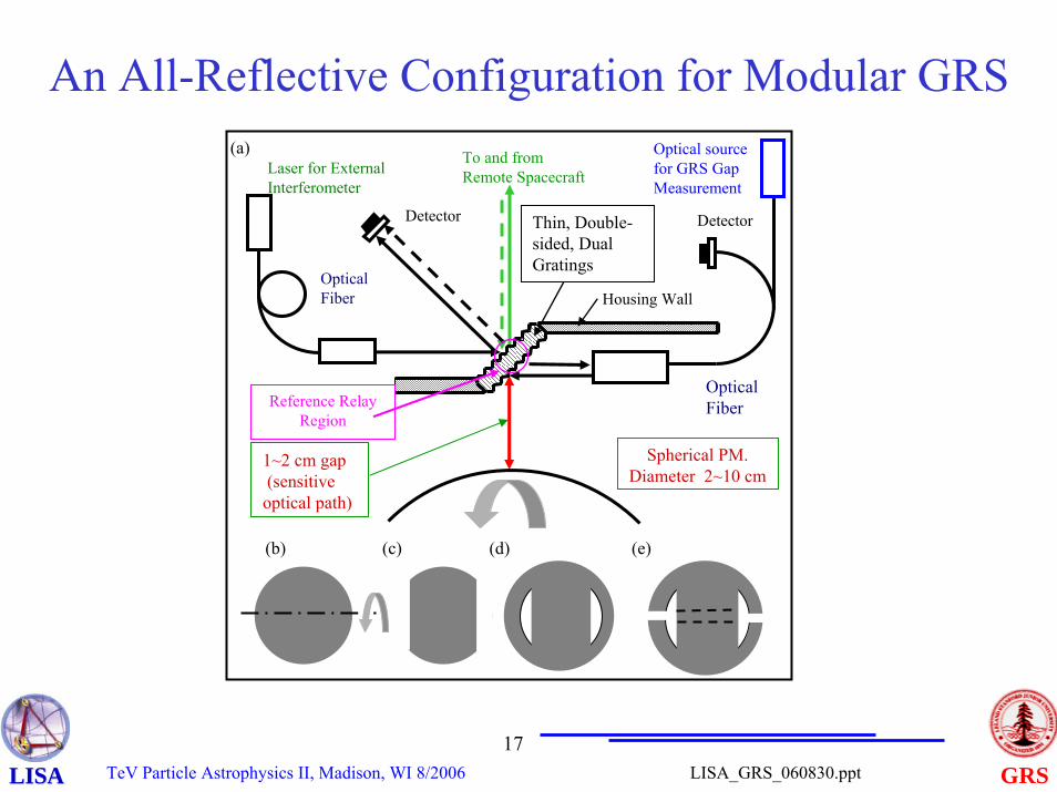
An All-Reflective Configuration for Modular GRS
(b) (c) (d) (e)
Housing Wall
Thin, Double-sided, Dual Gratings
Laser for External Interferometer
Optical Fiber
To and from Remote Spacecraft
Optical source for GRS Gap Measurement
Optical Fiber
Detector
Reference Relay Region
1~2 cm gap(sensitive optical path)
Spherical PM.Diameter 2~10 cm
(a)
Detector
TeV Particle Astrophysics II, Madison, WI 8/200618
GRSLISA_GRS_060830.pptLISALISA
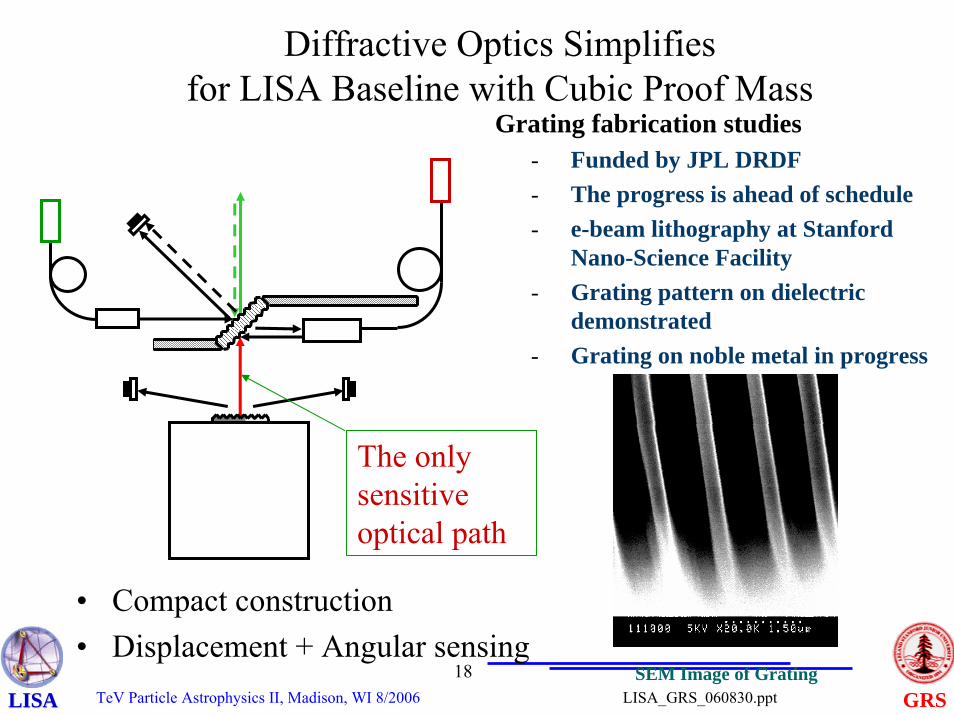
Diffractive Optics Simplifiesfor LISA Baseline with Cubic Proof Mass
• Compact construction• Displacement + Angular sensing
The only sensitive optical path
SEM Image of Grating
Grating fabrication studies- Funded by JPL DRDF- The progress is ahead of schedule- e-beam lithography at Stanford
Nano-Science Facility- Grating pattern on dielectric
demonstrated- Grating on noble metal in progress

TeV Particle Astrophysics II, Madison, WI 8/200619
GRSLISA_GRS_060830.pptLISALISA
• Multi-mirror design
• Telescope main heavy primary mirror and tube fixed
• Steering direction by moving (rotating) lighter tertiary and quaternary mirrors
• Assign coarse and fine adjustments to different mirrors
• Add CCD imager for seeking acquisition
CCD imager
Webb Space Telescope Multi-Mirror Steering Scheme
From interferometer laserto remote S/C
From remote S/C
TeV Particle Astrophysics II, Madison, WI 8/200620
GRSLISA_GRS_060830.pptLISALISA
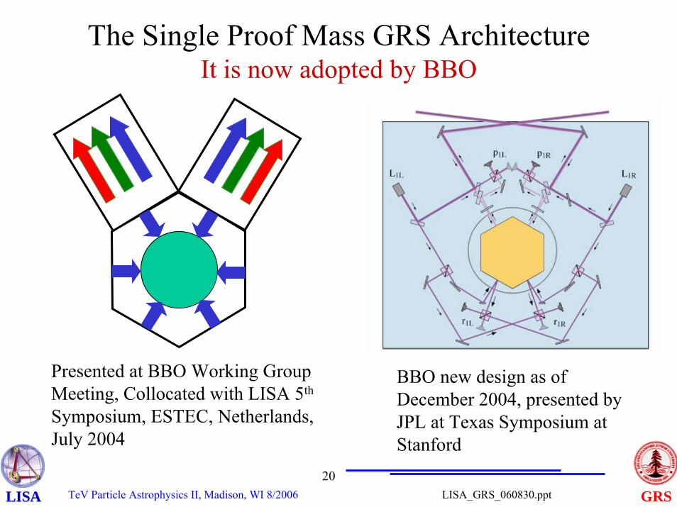
The Single Proof Mass GRS ArchitectureIt is now adopted by BBO
Presented at BBO Working Group Meeting, Collocated with LISA 5th
Symposium, ESTEC, Netherlands, July 2004
BBO new design as of December 2004, presented by JPL at Texas Symposium at Stanford
TeV Particle Astrophysics II, Madison, WI 8/200621
GRSLISA_GRS_060830.pptLISALISA
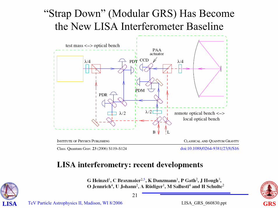
“Strap Down” (Modular GRS) Has Become the New LISA Interferometer Baseline
TeV Particle Astrophysics II, Madison, WI 8/200622
GRSLISA_GRS_060830.pptLISALISA
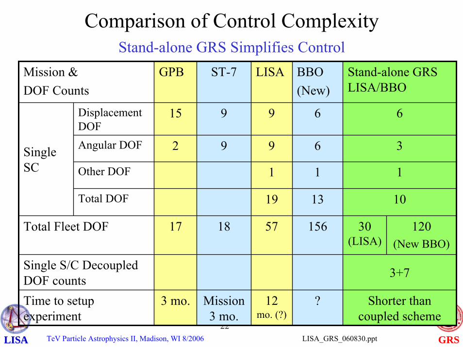
Comparison of Control ComplexityStand-alone GRS Simplifies Control
Mission & DOF Counts
GPB ST-7 LISA BBO(New)
Stand-alone GRS LISA/BBO
Displacement DOF
6
Angular DOF
Other DOF
Total DOF 19 13 10
Single S/C Decoupled DOF counts 3+7
Time to setup experiment
3 mo. Mission 3 mo.
12 mo. (?)
? Shorter than coupled scheme
120(New BBO)
3
1
Total Fleet DOF 17 18 57 156 30 (LISA)
15 9 9 6
2 9 9 6
1 1Single SC
TeV Particle Astrophysics II, Madison, WI 8/200623
GRSLISA_GRS_060830.pptLISALISA
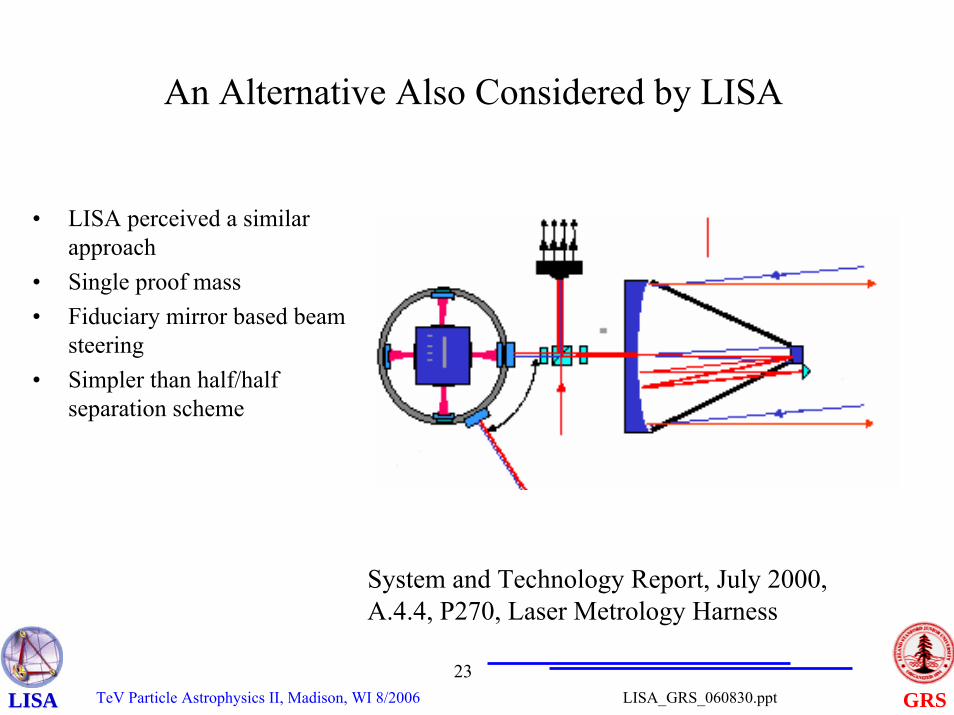
An Alternative Also Considered by LISA
• LISA perceived a similar approach
• Single proof mass• Fiduciary mirror based beam
steering• Simpler than half/half
separation scheme
System and Technology Report, July 2000,A.4.4, P270, Laser Metrology Harness
TeV Particle Astrophysics II, Madison, WI 8/200624
GRSLISA_GRS_060830.pptLISALISA
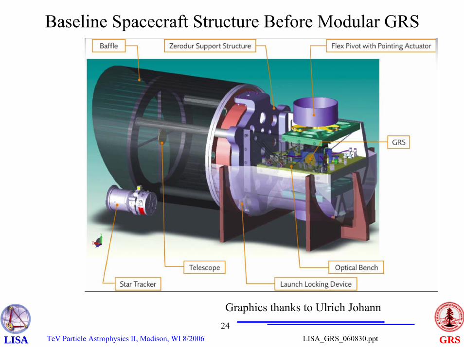
Baseline Spacecraft Structure Before Modular GRS
Graphics thanks to Ulrich Johann
TeV Particle Astrophysics II, Madison, WI 8/200625
GRSLISA_GRS_060830.pptLISALISA
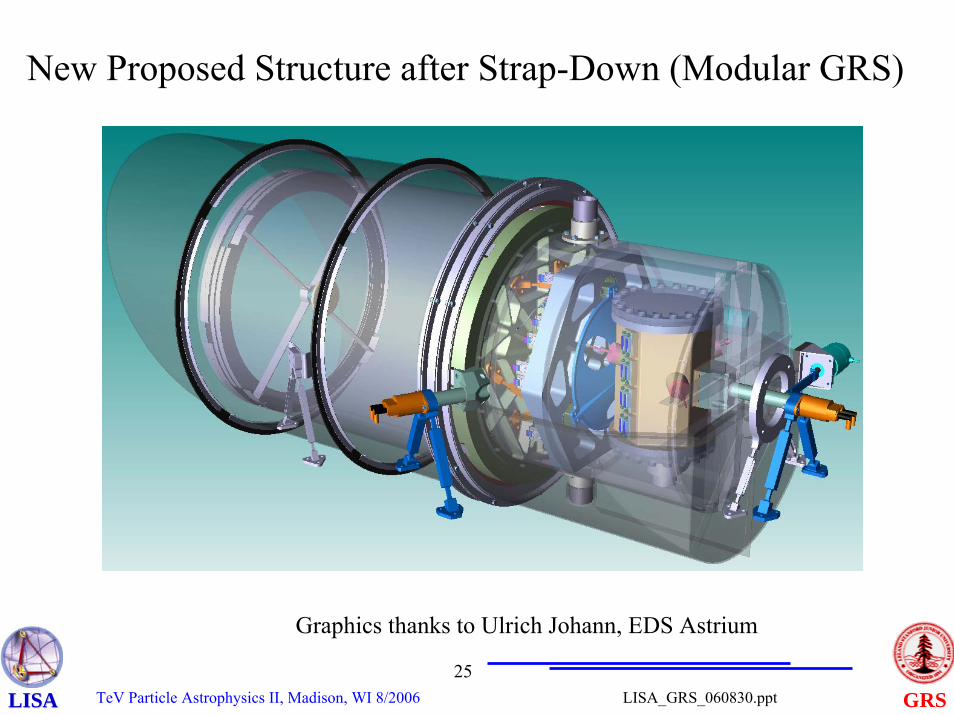
New Proposed Structure after Strap-Down (Modular GRS)
Graphics thanks to Ulrich Johann, EDS Astrium
TeV Particle Astrophysics II, Madison, WI 8/200626
GRSLISA_GRS_060830.pptLISALISA
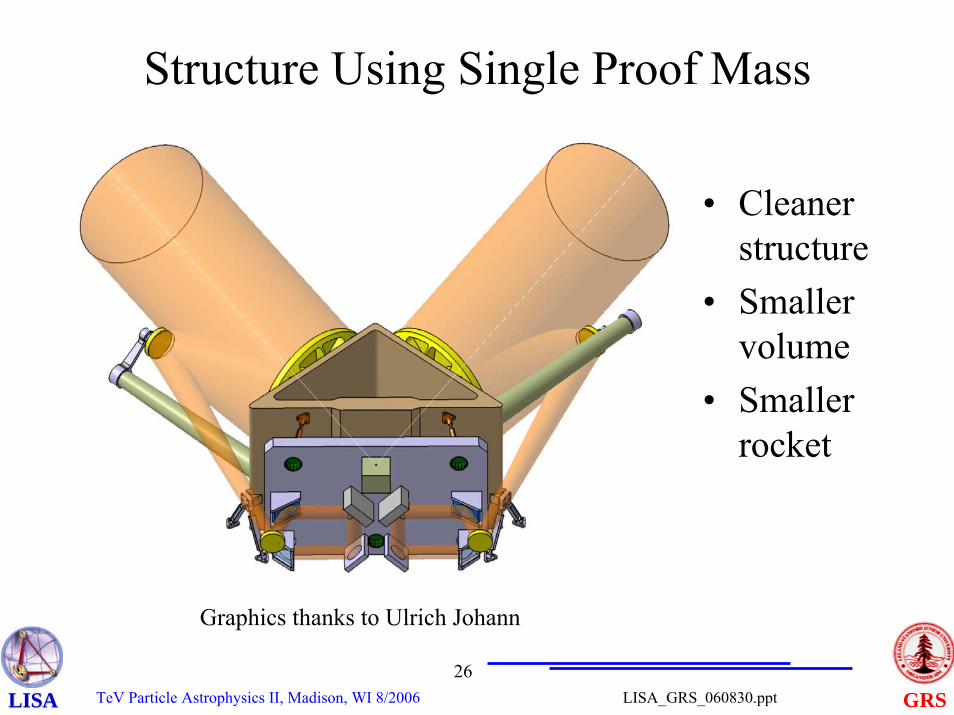
Structure Using Single Proof Mass
• Cleaner structure
• Smaller volume
• Smaller rocket
Graphics thanks to Ulrich Johann
TeV Particle Astrophysics II, Madison, WI 8/200627
GRSLISA_GRS_060830.pptLISALISA
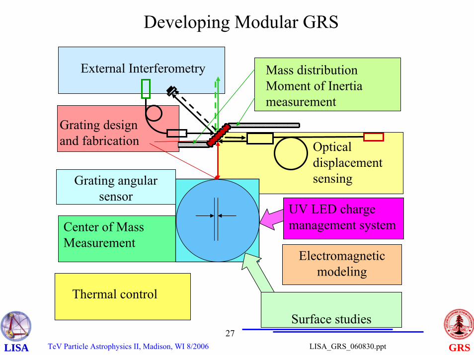
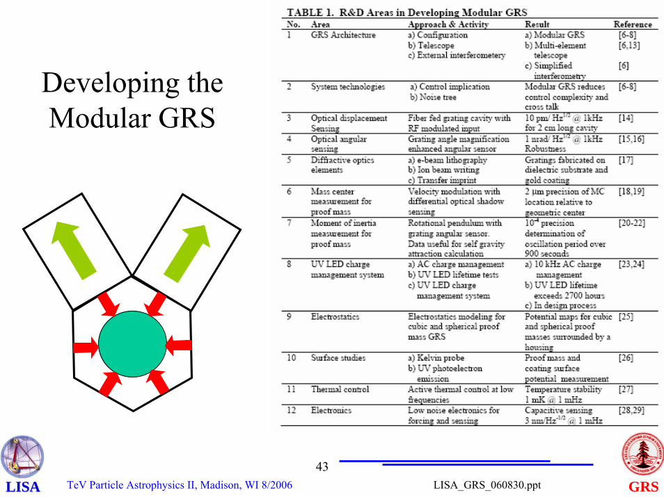
Developing Modular GRS
Thermal control
Center of Mass Measurement
Mass distributionMoment of Inertia measurement
Optical displacement sensing
Grating design and fabrication
External Interferometry
UV LED charge management system
Electromagnetic modeling
Surface studies
Grating angular sensor
TeV Particle Astrophysics II, Madison, WI 8/200628
GRSLISA_GRS_060830.pptLISALISA
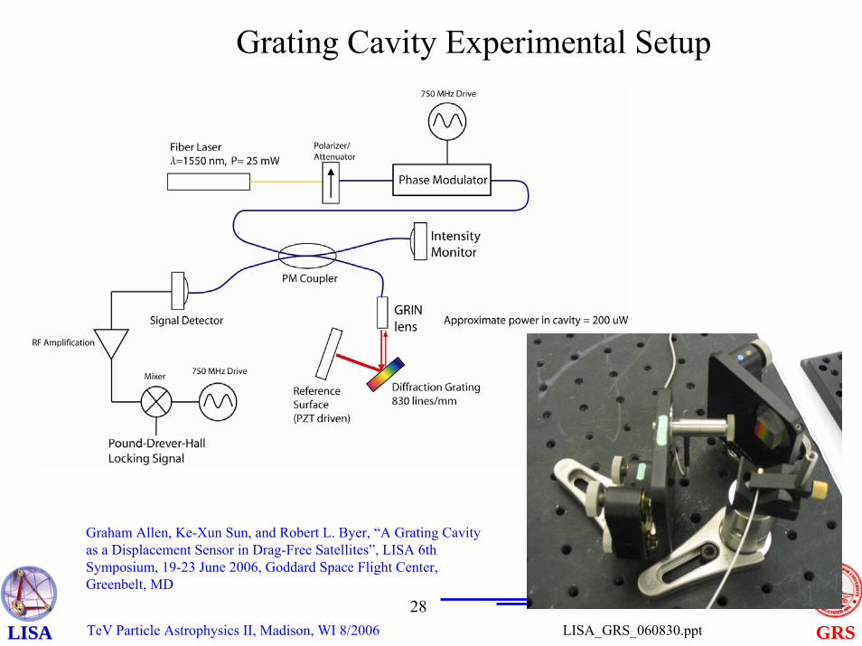
Grating Cavity Experimental Setup
Graham Allen, Ke-Xun Sun, and Robert L. Byer, “A Grating Cavity as a Displacement Sensor in Drag-Free Satellites”, LISA 6th Symposium, 19-23 June 2006, Goddard Space Flight Center, Greenbelt, MD
TeV Particle Astrophysics II, Madison, WI 8/200629
GRSLISA_GRS_060830.pptLISALISA
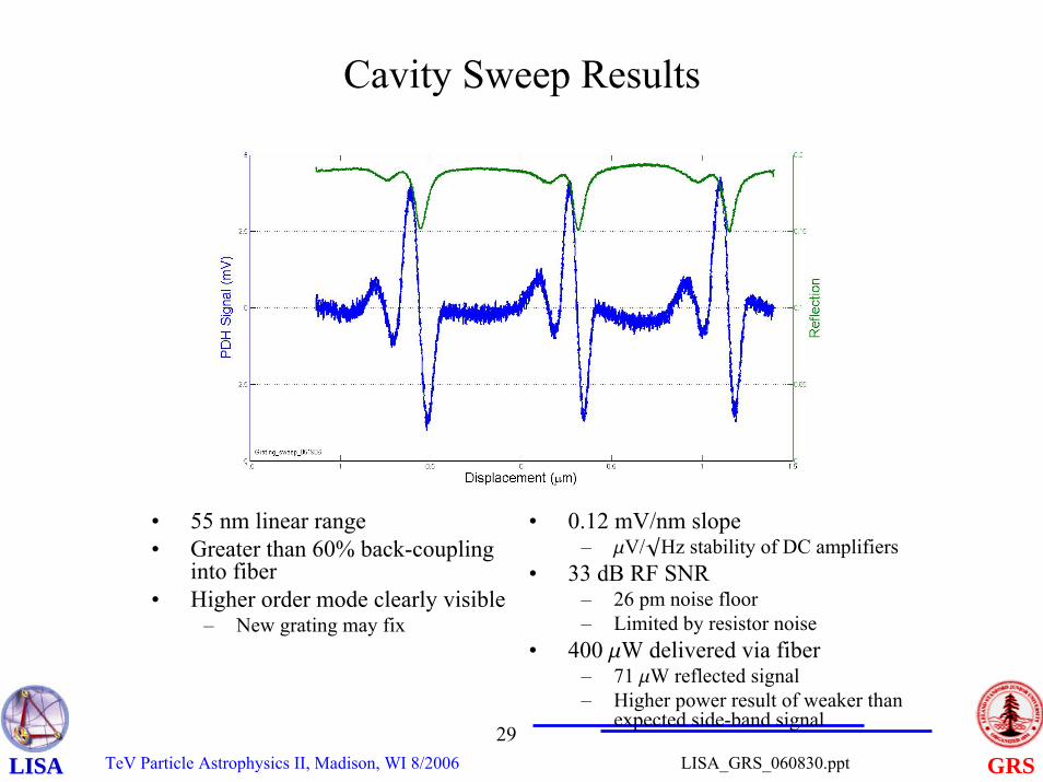
Cavity Sweep Results
• 0.12 mV/nm slope– mV/◊Hz stability of DC amplifiers
• 33 dB RF SNR– 26 pm noise floor– Limited by resistor noise
• 400 mW delivered via fiber– 71 mW reflected signal– Higher power result of weaker than
expected side-band signal
• 55 nm linear range• Greater than 60% back-coupling
into fiber• Higher order mode clearly visible
– New grating may fix
TeV Particle Astrophysics II, Madison, WI 8/200630
GRSLISA_GRS_060830.pptLISALISA
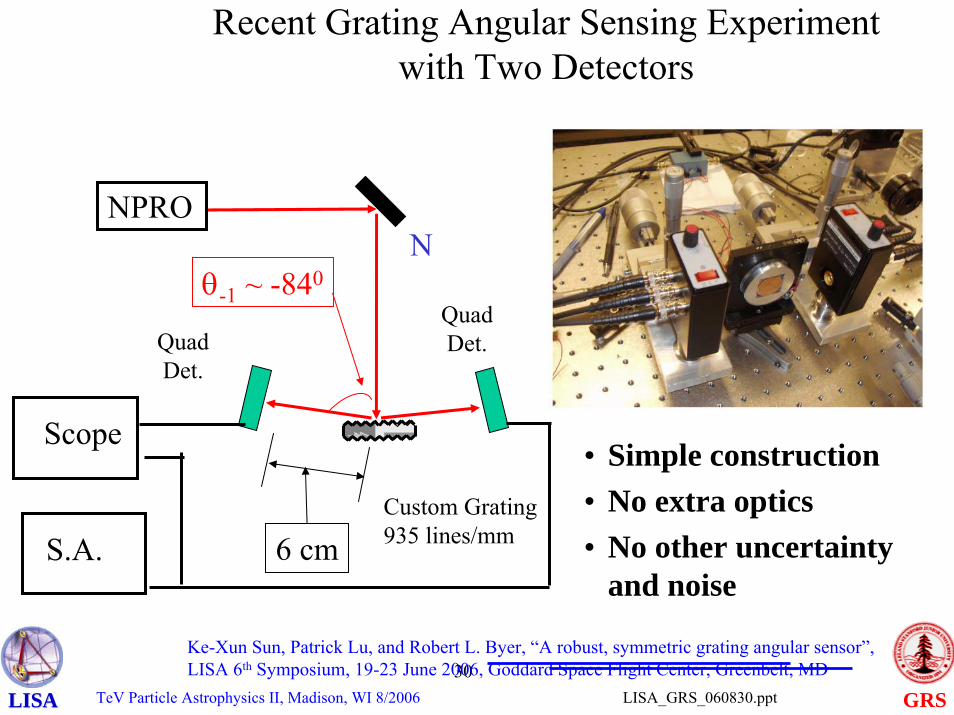
Recent Grating Angular Sensing Experiment with Two Detectors
Custom Grating 935 lines/mm
NPRO
Quad Det.
Scope
S.A.
Nθ-1 ~ -840
6 cm
Quad Det.
• Simple construction• No extra optics• No other uncertainty
and noise
Ke-Xun Sun, Patrick Lu, and Robert L. Byer, “A robust, symmetric grating angular sensor”, LISA 6th Symposium, 19-23 June 2006, Goddard Space Flight Center, Greenbelt, MD
TeV Particle Astrophysics II, Madison, WI 8/200631
GRSLISA_GRS_060830.pptLISALISA
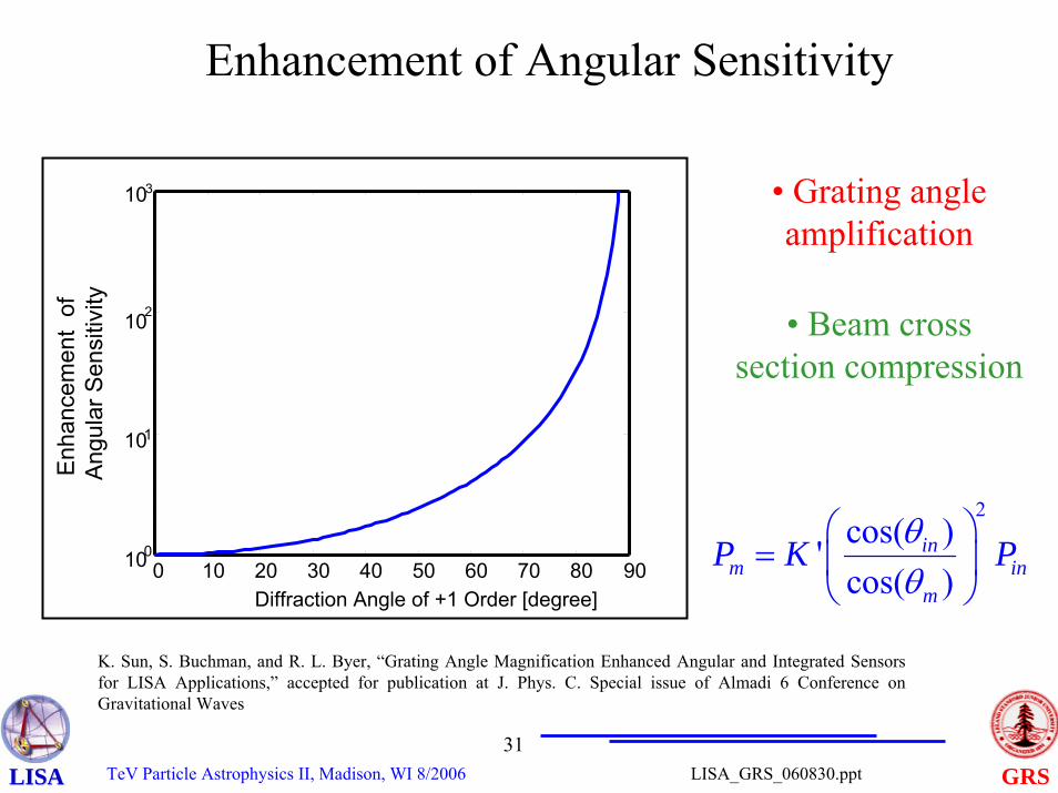
Enhancement of Angular Sensitivity
0 10 20 30 40 50 60 70 80 90100
101
102
103
Diffraction Angle of +1 Order [degree]
Enh
ance
men
t of
An
gula
r Sen
sitiv
ity
• Grating angle amplification
2cos( )'cos( )
inm in
m
P K Pθθ
⎛ ⎞= ⎜ ⎟
⎝ ⎠
• Beam cross section compression
K. Sun, S. Buchman, and R. L. Byer, “Grating Angle Magnification Enhanced Angular and Integrated Sensors for LISA Applications,” accepted for publication at J. Phys. C. Special issue of Almadi 6 Conference on Gravitational Waves
TeV Particle Astrophysics II, Madison, WI 8/200632
GRSLISA_GRS_060830.pptLISALISA
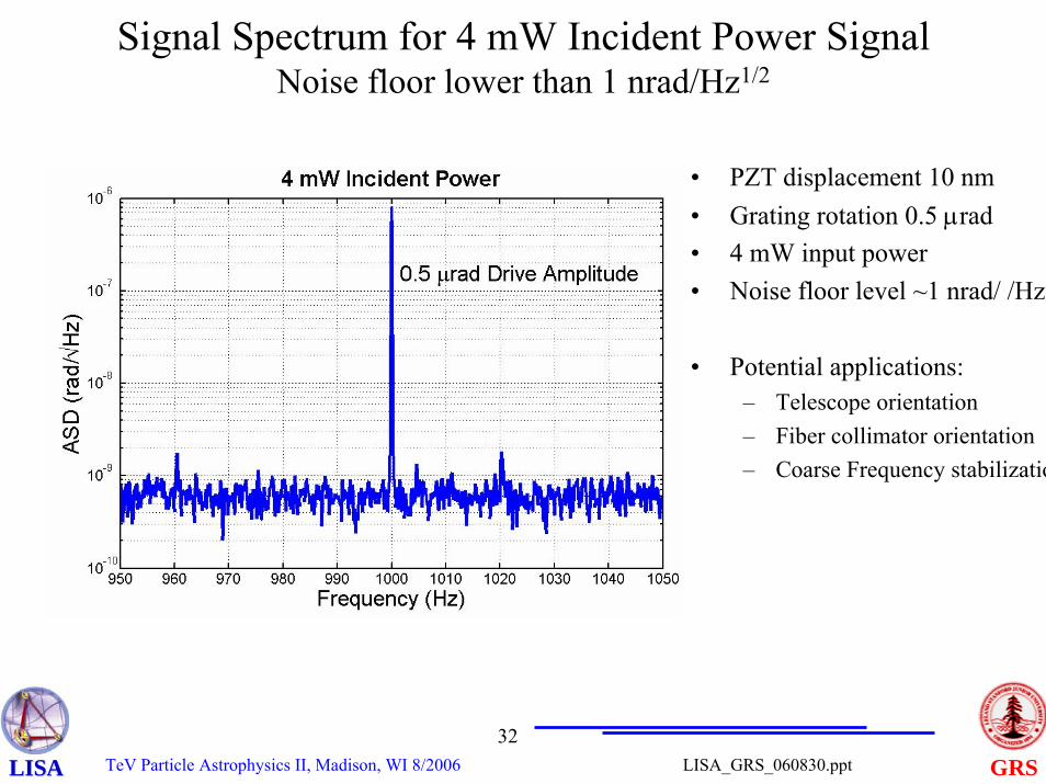
Signal Spectrum for 4 mW Incident Power Signal Noise floor lower than 1 nrad/Hz1/2
• PZT displacement 10 nm• Grating rotation 0.5 μrad• 4 mW input power• Noise floor level ~1 nrad/ /Hz1
• Potential applications:– Telescope orientation – Fiber collimator orientation– Coarse Frequency stabilizatio
TeV Particle Astrophysics II, Madison, WI 8/200633
GRSLISA_GRS_060830.pptLISALISA
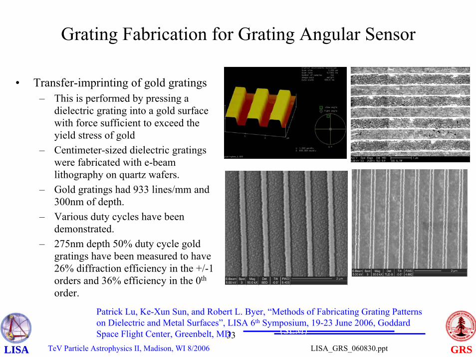
Grating Fabrication for Grating Angular Sensor
• Transfer-imprinting of gold gratings– This is performed by pressing a
dielectric grating into a gold surface with force sufficient to exceed the yield stress of gold
– Centimeter-sized dielectric gratings were fabricated with e-beam lithography on quartz wafers.
– Gold gratings had 933 lines/mm and 300nm of depth.
– Various duty cycles have been demonstrated.
– 275nm depth 50% duty cycle gold gratings have been measured to have 26% diffraction efficiency in the +/-1 orders and 36% efficiency in the 0th
order.
Dielectric grating, 50% duty cycle (AFM image)
Imprinted gold grating, 50% duty cycle (SEM)
Dielectric grating 25% duty cycle (SEM)
Patrick Lu, Ke-Xun Sun, and Robert L. Byer, “Methods of Fabricating Grating Patterns on Dielectric and Metal Surfaces”, LISA 6th Symposium, 19-23 June 2006, Goddard Space Flight Center, Greenbelt, MD
TeV Particle Astrophysics II, Madison, WI 8/200634
GRSLISA_GRS_060830.pptLISALISA
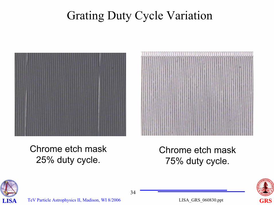
Grating Duty Cycle Variation
Chrome etch mask 25% duty cycle.
Chrome etch mask 75% duty cycle.
TeV Particle Astrophysics II, Madison, WI 8/200635
GRSLISA_GRS_060830.pptLISALISA
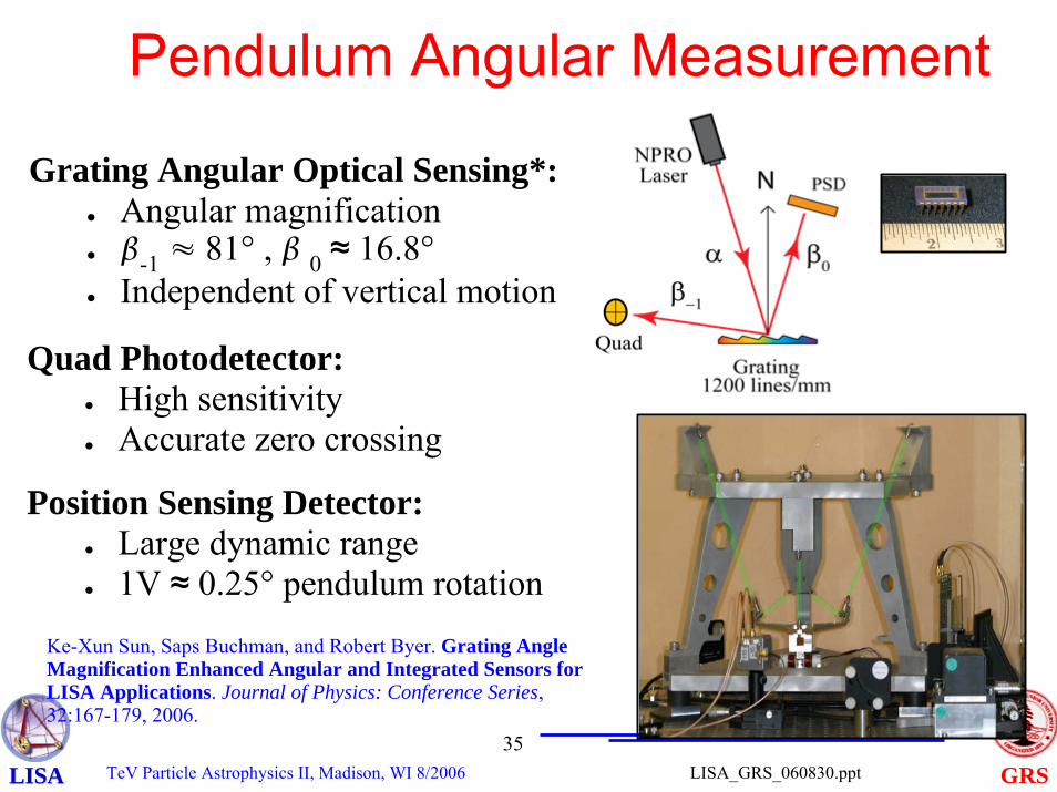
Pendulum Angular Measurement
● Measure inertia to below 1 part in 104
− Includes mass property uncertainties
Grating Angular Optical Sensing*:● Angular magnification● -1 ≈ 81° , 0 ≈ 16.8°● Independent of vertical motion
Ke-Xun Sun, Saps Buchman, and Robert Byer. Grating Angle Magnification Enhanced Angular and Integrated Sensors for LISA Applications. Journal of Physics: Conference Series, 32:167-179, 2006.
Quad Photodetector:● High sensitivity● Accurate zero crossing
Position Sensing Detector:● Large dynamic range● 1V ≈ 0.25° pendulum rotation
TeV Particle Astrophysics II, Madison, WI 8/200636
GRSLISA_GRS_060830.pptLISALISA
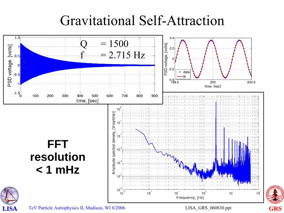
Gravitational Self-AttractionQ = 1500f = 2.715 Hz
FFTresolution < 1 mHz
TeV Particle Astrophysics II, Madison, WI 8/200637
GRSLISA_GRS_060830.pptLISALISA
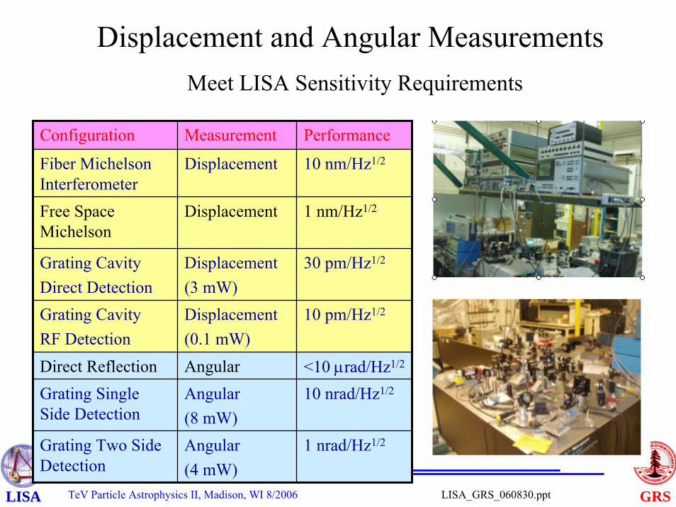
Displacement and Angular MeasurementsMeet LISA Sensitivity Requirements
Configuration Measurement Performance
Fiber Michelson Interferometer
Displacement 10 nm/Hz1/2
1 nm/Hz1/2
Grating CavityDirect Detection
Displacement(3 mW)
30 pm/Hz1/2
Grating CavityRF Detection
Displacement(0.1 mW)
10 pm/Hz1/2
Direct Reflection Angular <10 μrad/Hz1/2
Grating Two Side Detection
Angular(4 mW)
1 nrad/Hz1/2
Grating Single Side Detection
Angular(8 mW)
10 nrad/Hz1/2
Free Space Michelson
Displacement
TeV Particle Astrophysics II, Madison, WI 8/200638
GRSLISA_GRS_060830.pptLISALISA
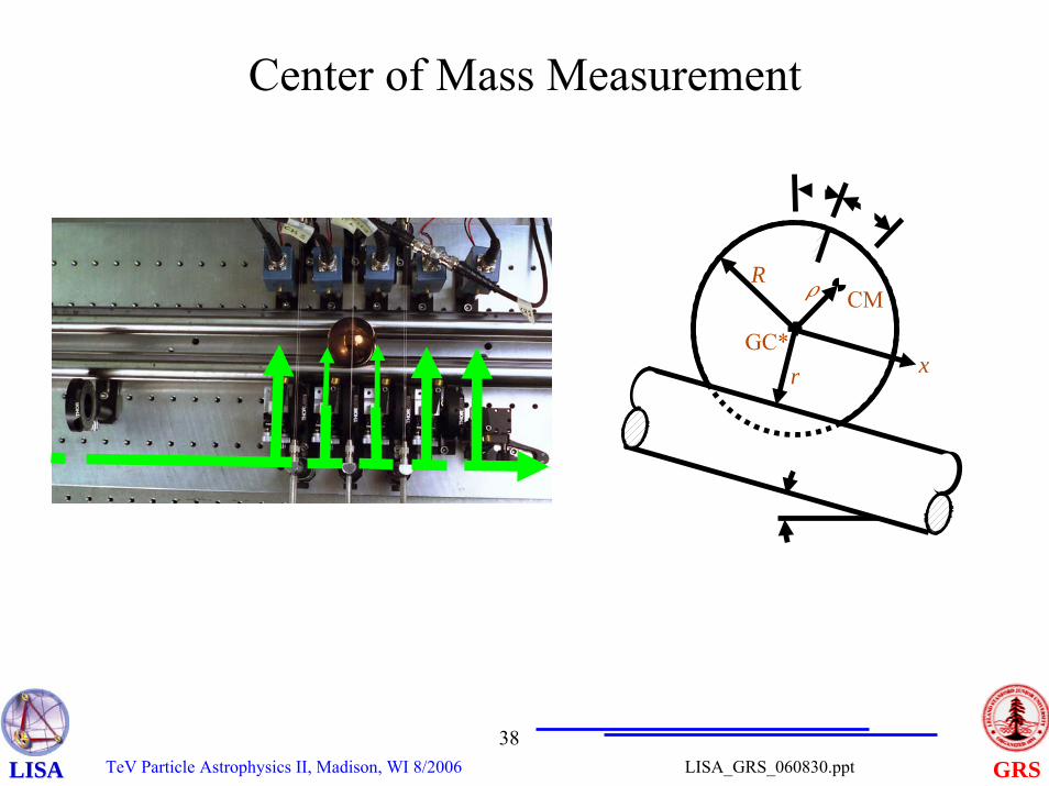
Center of Mass Measurement
CM
GC*
R
r
�
�
x
�
TeV Particle Astrophysics II, Madison, WI 8/200639
GRSLISA_GRS_060830.pptLISALISA
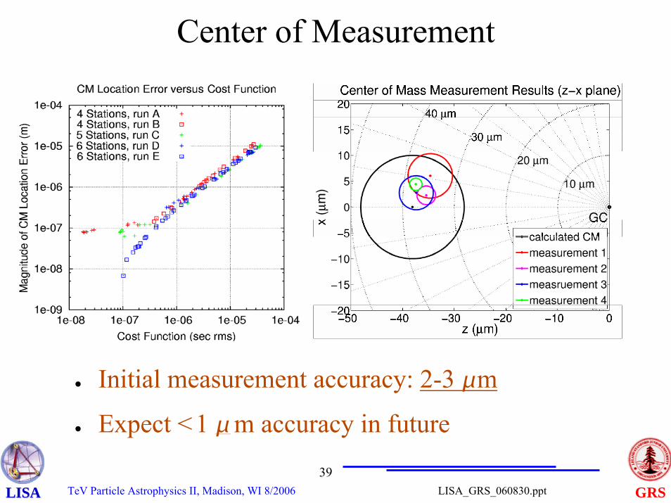
Center of Measurement
● Initial measurement accuracy: 2-3 m
● Expect <1 m accuracy in future
TeV Particle Astrophysics II, Madison, WI 8/200640
GRSLISA_GRS_060830.pptLISALISA
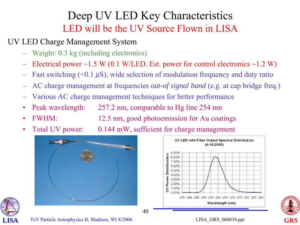
Deep UV LED Key CharacteristicsLED will be the UV Source Flown in LISA
UV LED Charge Management System– Weight: 0.3 kg (including electronics)– Electrical power ~1.5 W (0.1 W/LED. Est. power for control electronics ~1.2 W)– Fast switching (<0.1 μS), wide selection of modulation frequency and duty ratio– AC charge management at frequencies out-of signal band (e.g. at cap bridge freq.)– Various AC charge management techniques for better performance• Peak wavelength: 257.2 nm, comparable to Hg line 254 nm• FWHM: 12.5 nm, good photoemission for Au coatings• Total UV power: 0.144 mW, sufficient for charge management
TeV Particle Astrophysics II, Madison, WI 8/200641
GRSLISA_GRS_060830.pptLISALISA
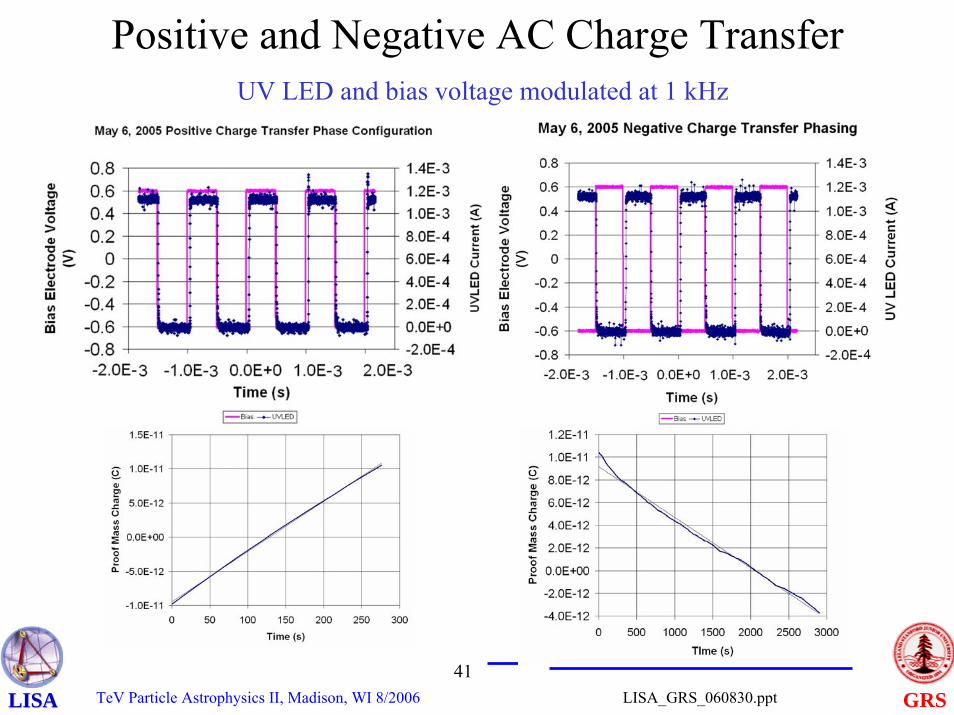
Positive and Negative AC Charge TransferUV LED and bias voltage modulated at 1 kHz
TeV Particle Astrophysics II, Madison, WI 8/200642
GRSLISA_GRS_060830.pptLISALISA
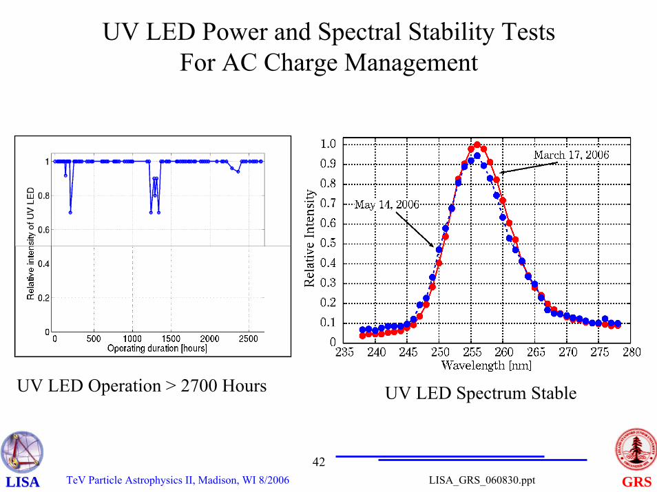
UV LED Power and Spectral Stability Tests For AC Charge Management
UV LED Operation > 2700 Hours UV LED Spectrum Stable
TeV Particle Astrophysics II, Madison, WI 8/200643
GRSLISA_GRS_060830.pptLISALISA
Developing the Modular GRS
TeV Particle Astrophysics II, Madison, WI 8/200644
GRSLISA_GRS_060830.pptLISALISA
Summary
• LISA GRS technology made much progresses– LTP ground testing performance met requirements– LTP launch is still on schedule
• Novel LISA GRS architecture– Modular GRS (“Strap Down”) is adopted as the new
LISA IMS/GRS baseline– Single proof mass configuration under serious
considerations– Much progress in modular GRS development