Leybold, ULTRATEST UL 100 PLUS, Helium Leak … · ULTRATEST UL 100 PLUS...
60
vakuumtechnik Vakuum- Verfahrenstechnik GA 10.207/4 Gebrauchsanweisung Operating Instructions Mode d'emploi MeB-und Analysentechnik LEYBOLDAG Ein Unternehmen der Degussa ULTRATEST UL 100 PLUS Helium-Leck-Detektor-Portable Helium-Leak Detector, Portable Detecteur de fuites a helium portatif Software-VersionlVersion 3.x du logiciel 155 82, 155 83, 896 38
Transcript of Leybold, ULTRATEST UL 100 PLUS, Helium Leak … · ULTRATEST UL 100 PLUS...
vakuumtechnik VakuumVerfahrenstechnik
GA 10.207/4
Gebrauchsanweisung Operating Instructions Mode d'emploi
MeB-und Analysentechnik
LEYBOLDAG Ein Unternehmen der Degussa
ULTRATEST UL 100 PLUS Helium-Leck-Detektor-Portable Helium-Leak Detector, Portable Detecteur de fuites a helium portatif
Software-VersionlVersion 3.x du logiciel
155 82, 155 83, 896 38
___________________________ mm ACHTUNO r Vor ledsr /nan!Jpruchnahme des ServIces Itd.s. aUI GrUnden der ArbeltBslcherhs/t und de. Umweltsch lib:es notwlilndlg. am oder 1m Gerlt baflndllche. gaflihrll· che ste"e (z.a 1m S/nne EG-Alchfflnle L 380, 1976 /1979 odor VaG 16) anzuzelgen und zu deklarleren.
Inhalt 1 1.1 1.1.1 1.1.2 1.1.3 , .1.4
1.2 1.2.1 1.2.2 1.2.3
1.3 1.3.1
1.3.1.1 1.3.2 1.3.3 1.3.4 1.3.5 1.3.6
1.4 1.4.1 1.4.2
2 2.1 2.1.1
2.1.2
2.1.3
2.2
2.2.1 2.2.1.1 2.2.1.2 2.2.1.3
2.2.2
2.2.3 2.2.4
2.2.5
2.2.6
2.2.7
2.2.8
2.2.8.1
2.2.8.2
2.2.8.3
2.2.8.4 2.2.9
2.2.10 2.2.'1 2.2.12 2.2.13
2
Baschrelbung ••••.•••... Allgemeine Angaben •..•• Bezeichnung ..•.•••.•.•.. Verwendungszweck ..••... KennzeichnungS5teUe BaugruppenObersicht .••.••
Technische Daten •••••.• Physikalische Daten ••••... Elektr/sche Daten ••.••..•• Sonstige Daten ••••... •••.
4 4 5 5 5 5
6 6 7 7
Technlsche Beschrelbung 8 Beschreibung des NachweisPrinzips (Gegenstrom) ••.•.. 9 Ventilstellung ••...•.•.••• 9 Vorval<uumpumpe •••••••• 10 Turbo-Molekularpumpe .••. 10 Massenspaktrometer ...•.. 10 lonenquelle ••••.••.....• 11 lonenfa.nger und VerstArker 11
Ausstattung ........... 12 Lieferumfang •••.•.•.••. 12 ZubehOr ••••••••..••.•. 12
Bedlenung und Batrleb •. 14 AufBtelien des UL 100 PLUS 14 Obersicht der Bacien- und Anzeigeelemente •••••..• 14 Vorbereitung zur Inbetrieb-nahme •..•...••••••.•. 15 Betriebstemperatur .•.•... 16
Beschrelbung der Bedlenfunkllonen ....... 16 NetzanschiuB ..•.••.••.• 16 Elektrlscher AnschluB •.••• 16 Netzschalter "EIN/AUS· ... 17 Netzspannungsausgang fOr ZusatzgerAte •.••••••.•• 17 Taste "START" und "STOPNENT" ••••.•..•. 17 Werteingabe~Taste ••••.•• 18 Mel3bereichswahl-Taste "Automatik" rTriggenogik" 19
MeBbereichswahl-Taste "HAND" .....•..•.••.. 19 Nullpunkt-Taste "Auto-Zero" 19
Multifunktions-Taste "Akustisches Signal" 19 Multifunktions-Taste "Trigger und Kalibrierung" •• 20 Funktion "Trigger 1 und 2" Normal ................ 20 Funktion "Trigger 1 und 2" Invers ••.•••..••••.•. . . 21 Sonderfunktion Trigger 1 und 2 (Geratezustand) 22 Funlction "Kalibrierung" ..•. 22 Taste fOr Eingabe-Ende "ENTER" ••..•••.••.••. 22 Permanenter parameterspeicher 23 Gasballastven1ll .......... 23 TestanschluB •..•.•.•... 24 Zusatzliche Bedieneinrlchtungen 24
IMPORTANTl Before conlultfng tho Servico Dopt., ploolo dec/are, for fila Btlke or oporatfonal 'alsty and environmental protection, any toxic or other hazardoUB productt (e.g. a, defined In EEC dlroctive L 360, 1976/1979 or VBG 16) existing In or around tho BpparBfu, to be BOrY/cod.
Contents 1 Description """""'" 4
4 5 5 5 5
1.1 General ............... . 1.1.1 Designation. • • • • . . . . . •.• 1.1.2 Purpose ••.......••.•..• 1.1.3 Rating Plate ••.......••.. 1.1.4 Modules ..•••••......••.
1.2 Technical Data ......... . 6 6 7 7
1 .2.1 Physical Data .."" .... " 1.2.2 Electrical Data .......... . 1.2.3 Other Data .•.•.•..••...•
1.3 1.3.1
1.3.1.1 1.3.2 1.3.3 1.3.4 1.3.5 1.3.6
1.4 1.4.1 1.4.2
2 2.1 2.1.1
2.1.2
2.1.3
2.2
2.2.1 2.2.1.1 2.2.1.2 2.2.1.3
2.2.2
2;2.3 2.2.4
2.2.5
2.2.6
2.2.7
2.2.8
2.2.8.1
2.2.8.2
2.2.8.3
2.2.8.4 2.2.9
2.2.10 2.2.11 2.2.12 2.2.13
Technical Description .... 8 D!3scription of Leal< Detection Principle (CounteriIQw) ....• 9 Valve positions •••.•..•. -.. 9 Backing Pump .......••• 10 Turbo-Molecular Pump •..• 10 Mass Spectrometer .••••.. 1 0 Ion Source ..... "".... 11 Ion Collector and Amplifier 11
Equipment ............ 12 Standard Specification •••. 12 Accessories .......••.•• 12
Operation ........ '. . . . . 14 Setting Up 'he UL 100 PLUS 14 Layout of Contrals and Displays 14
Preparations for Initial Start-Up ..••.•••..••••• 15 Operating T amparature ._... 16
Description of controis " 16
Mains Connections '. . • . • . • 16 Electrical Connections .••.. 16 "ON/OFF" Power Switch " 17' Mains Outlet for Auxiliary Equipment ........•••.. 17 Pushbutton "START" and "STOPNENT" •........• 17 Parameter Pushbutton ••••• 18 Range Selector Pushbutton "Automatic" rTrigger logic" 19
Measuring Range Selector "Manual" •.......•..... 19 Pushbutton "Auto Zero" ••. 19
Mum-Function Pushbutton "Acoustic Signal" ....••.. 19 Multl~Function Pushbutton "Trigger and Calibration" 20 Function "Trigger 1 and 2" Nonnal •....•••••••...• 20 Function "Trigger 1 and 2" Invers •. .• .• . •••••••••• 21 Special function Trigger 1 and 2 (equipment status) '" 22 Function "Calibration" 22 "ENTER" Pushbutton ..... 23
Permanent Parameter Memory 23 Gas Ballast Valve ........ 23 Test Connection ••....••. 24 Additional,Features ....••• 24
ENrIOHI Pour chlB ra/BonB 1180B i la rkurit8 et i I'onvlronnomont, prlero d'lndlquer a chaqua domande d'intervenf/on du Borvlce aprea-vonte fOB pradu'" dangorewc (p. 8l\'. au termo dOB directlVeB do la CE L 380, 197611979 ou vea 18) BO trouvant Bur ou dBnB /'eppef8l1.
Sommalre 1 Description •............. 4
4 5 5 5 5
1.1 Generalltes ............. . 1.1.1 Designation ••.•...•.•••.. 1.1.2 Emploi •....••...•.•..••• 1.1.3 Signalisations .••.....•..•• 1.1.4 Composition modulalre ..••..
1.2 Caracterlstlques technlquea e e i i
1.2.1 Caracteristiques physiques ..• 1.2.2 Caracteristiques electriques •.. 1.2.3 Autres caract8ristiques ••.•••
1.3 1.3.1
1.3.1.1 1.3.2 1.3.3 1.3.4 1.3.5 1.3.6
1.4 1.4.1 1.4.2
2 2.1 2.1.1
2.1.2
2.1.3
2.2
2;2.1 2.2.1.1 2.2.1.2 2.2.1.3
2.2.2
2.2.3 2.2.4
2.2.5
2.2.6
2.2.7
2.2.8
2.2.8.1
2.2.8.2
2.2.8.3
2.2.8.4 2.2.9
2.2.10 2.2.11 2.2.12 2.2. 13
Description technique Description du prinCipe de dateclion (contre·flux) Positions des robinets ..•.... Pompa a vide primafre ..•.. 1 ( Pompe turbomoleculaire •..• 1 ( SpeotromBtre de masse .••. 1 ( Source d'ions ...•..•••... 1· Col1ecteur d'ions at amplificateur 1"
Equlpemen, ............ 1: Equipement Standard .,. . • • . 1: Accessoires •.••...••...• 1:
Utilisation •.••.•••...... 1 ' Installation de UL 100 PLUS 1, Elements de commande et d'affichage .•.•••...•.... 1, Preparatifs pour la premiere mise en service .......... Temperature de service •...•
Description des fonctions de commande ............ . Raccordement au secteur '" Raccordement electrlque .••. 1 Interrupteur "MARCHE/ARRET" 1 Sortie de tension secteur pour appareils supplementaires '" Touches "START" at "STOPNENT" .••....••.. Touche d'entree de valeurs •• Touche de selection "automatique" rtrigger log. II des gammes de mesure •••.•.. Touche de selection "manuel1e" des gammas de mesure •... TOuche de remise ill zero "autozero" .•..•......••. Touche multifonction "signal acoustique" Touche multifonction "trigger at calibrage" Fonation "triggers 1 at 2'" normale ••••...•..•.•••. Fonction "triggers 1 at 2" inverse ••••••...•.•.. '" Fonction speciale triggers 1 et 2 (atat de I'appareil) ••••••.•• Fonction "caIibrage" •••.... Touche de confirmation d'entree "ENTER" ..•.•... Memoirs perm. des parametres Robinat de lest d'air ••...•. Raccord test ......... ... . Dispositifs supplementaires .•

mm~ __________ ~ ______ ~ __ __ 2.2.13.1 SchlOsselschalter .••.•... 25 2.2.13.2 Multifunktions-Schnittstelle .. 27 2.2.13.3 Trigger-Ausgange Trigger 1 + 2 28 2.2.13.4 Teilstromventilansteuerung 29
2.2.13.5 Femsteuerung der Lecksuch-funktionen .••••..•••.••• 30
2.2.13.6 AnaJog-Spannungs-AusgAnge 30 2.2.13.7 Analog-Spannungs-Ausgang
fOr den EinlaBdruck (PE) .•. 31 2.2.13.8 KopfhOrer-AnschluB •••.•. 32
2.2.13.9 Halskette ..•••.•••..... 32 2.2.13.10 Verbindung zwischen Bedien-
2.3
2.3.1
2.4 2.4.1
2.4.2
2.4.3
2.4.3.1 2.4.3.2
2.4.3.3 2.4.4
2.4.5
2.4.6
2.4.6.1 2.4.6.2 2.4.7
2.4.7.1
2.4.7.2 2.4.7.3
2.4.7.4
2.4.8 2A.B.1
2.4.8.2
2.5
2.6 2.6.1 2.6.2
2.6.3
2.6.4
2.7
2.7.1 2.7.2 2.7.3
einheit und Lecksuohmodul 32
Inbetrlebnahme und Abo pumpen elneB ProfllngB •. 33 Einstellen der Uhrzeit und Datum •...•••..•..•••. 36
Betrlebaarten .•..•••• ~ . 37 Obersicht der Betriebsarten .••••••.... 37 Vakuum-Lecksuche mit prOfling •••..••..•...•• 38 Handhabung des PrOfIings bei lokaler und integraler Lecksuche ..••••....•.• 38 lokale Lecksuche ......•. 38 Bestimmung der Ansprech-zeit •.•..••....•••.•.. 39 Integrale Lecksuche ...... 39 Besonderheiten bel groBem Volumen elnes PrQfIings ... 39 Besonderheilen bei kleinem Volumen eines PrQfIings '" 39 Besonderheiten bei kleinen und groBen Leckraten .•.•• 40 Kleine Leckraten •.•.•.•.. 40 GroBe Leckraten ..•••.•.• 40 Besondere LecksuchablAufe 40
Option Teilstrompumpsatz TPS UL 100 PLUS .......... 40 Sonstige Pumpsatze .••.•• 42 Betrieb des Lecksuchmoduls ohne Pumpmodul .•..•... 43 Lecksuchmodul mit anderer Vorvakuumpumpe am VorvakuumanschluB ........• 43 SchnOffeliecksuche •..•.•. 44 Lecksuche mit Standard· schnOffler ..........••.. 45 Lecksuche mit Hefium·SchnOffier QUICKTEST QT 100 ..... 45
AuBerbe1riebsetzung .... 45
Kallbrieren und Tunen .•. 46 Tunen ..•.••••••..••.• 46 Kalibriereri mit eingebautem Testleck •.•.. 46 Kalibrieren mit externem Testleck .••.••..•..••.• 47 Kalibrieren im SchnUffelbetrieb .....••.. 48
Servlcefunktlon der Eleklronlk-Elnhelt ....... 49 Statusanzeige _. . • • • . • . . .. 52 Fehlermeldung ......•••. 53 Abgleich der Massen-position ................ 55
22.13.1 Keylock Switch .......... 25 2.2.13.2 Multi-Function Interface ..•• 27 2.2.13.3 Trigger OutpUts Trigger 1 + 2 28 2.2.13.4 Driving of the Partial-Flow •• 29
2.2.13.5 Remote Control of the Leak Testing Functions ...•.•.• 30
2.2.13.6 Analog voltage outputs .•.. 30 2.2.13.7 Analog voltage output for
the inlet pressure (PE) •••.• 31 2.2.13.8 Headset Socket .•...••.• 32
2.2.13.9 Carrying Chain .....•..•• 32 2.2.13.10 Connection between Control
2.3
2.3.1
2.4 2.4.1
2.4.2
2A.3
2.4.3.1 2.4.3.2
2.4.3.3 2.4.4
2.4.5
. 2.4.6
2.4.6.1 2.4.6.2 2.4.7
2.4.7.1
2.4.7.2 2.4.7.3
2.4.7.4
2.4.8 2A.B.1
2.4.8.2
2.5
.2.6 2.6.1 2.6.2
2.6.3
2.6.4
2.7
2.7.1 2.7.2 2.7.3
Unit and Leak Detection Module ••....•..••... ,. 32
Initial Stan-Up and Evacuation of a Test Object ••..•... 34 Entering time and date .... 36
Opemlng Modes .••..•. 37 Overview of the operating modes ..••..••. 37 Vacuum Leak Detection with Test Object ..•..•...••. 38 Handling of the Test Object for Local or Integral Leak Detection .•..•..••..•.. 38 Local Leak Detection .•... 38 Determination of Response Time ..••..•.••..••.•• 39 Integral Leak Detection •... 39 Special Features of Large-Volume Test Objects 39 Special Features of Smail-Volume Test Objects 39 Special Features of Low and High Leak Rates .•......• 40 Low Leak Rates ......... 40 High Leak Rates ..••..•.. 40 Special Leak Detection Procedures ...•..•...••. 40 Optional Partial-Flow Pump Set TPS UL 100 PLUS ...... 40 Other pump sets ........ 42 Leak Detection Module without Pump Module .•••.•...•• 43 Leak Detection Module with another Backing Pump Connected to the Forevacuum Inlet •.•• 43 Sniffing Leak Test .•...... 44 Leak Testing with Standard Sniffer •.••..•..•..•... 45 Leak Testing with QUICKTEST QT 100 Sniffer Probe ••... 45
Switching Off ...•...... 45
Calibration and Tuning .. 46 Tuning ...•..........•• 46 Calibration with the built-in calibrated leak •..••..... 46 Calibration with an extemal calibrated leak .....••.•• 47 Calibration in the sniffer mode................. 48
Service Functions of the EI~ronlcs Unit .....••. 49 Status Indication ...•..•.. 52 Error Messages ..••..... 53 Alignment of Mass Position ••••...•..••... 55
22.13.1 Commutate IX a de ........ 25 2.2.13.2 Interlace multifonction ..••••• 27 2.2.13.3 Sorties trigger, et trigger 2 .. 28 2.2.13.4 Commande du robinet flux
partiel . . . . . . . . . . . . . . . . . . 29 2.2.13.5 Telecommande de la detection
de fuite ...•••••• ;....... 30 2.2.13.6 Sorties tension analogique ... 30 2.2.13.7 Sortie de tension analogique pour
la pression d'admission (pE)· 31 2.2.13.8 Raccordement pour casque
d'ecoute ....•...•••...•• 32 2.2.13.9 Chaine de suspension ...... 32 2.2.13.10 CAble de connexion entre
2.3
2.3.1
2.4 2.4.1
2.4.2
2.4.3
2.4.3.1 2.4.3.2
2.4.3.3 2.4.4
2.4.5
2.4.6
2.4.6.1 2.4.6.2 2.4.7
2.4.7.1
2.4.7.2 2.4.7.3
2.4.7.4
2.4.8 2.4.8.1
2.4.8:2
2.5
2.6 2.6.1 2.6.2
2.6.3
2.6.4
2.7
2.7.1 2.7.2 2.7.3
l'unitS de commande at Ie module-detecteur ....... 32
Premiere mise en service et premiere evacuation d'une piece 35 Introduction de I'haure et de la date ............... 36
Modes ~e service •..••..• Aperpu des modes de service ••.•••.••..... Detection de fuites sur piece sous vide ... "...... Travail sur la piece pour les detections de fuites locale et intregrale •••......•....• Detection de fuite locale •... Determination du temps de niponse ....•....•..•..• Deteciion de fulte integrale •• Particulantes pour les pieces de grand volume .......... ParticularitBs pour les pieces de petit volume .......•••• Particularites pour les taux de fuite minimes at importants •• Petits taux de fuite •.••..... Importants taux de fuite ••... Procedures speciales de detection •.•..•..•....•• Option groupe de pompage de flux partiel TPS UL 100 PLUS Autres groupes de pompage Service du module·d8tect.eur sans module-pompe ..•••.. Module-d8tecteur avec une autre pompe sur Ie raccord vide primaire •••••..•.•.•. Detection avec renifleur ..•.• Detection avec renifleur _dard ....... ' ....... . Detection avec ren.ifleur rapids QT 100 ....•.....•
37
37
38
38 38
39 39
39
39
40 40 40
40
40 42
43
43 44
45
45
Arrirt de I'apparel! ...•••. 45
C8librage et syntonlsatlon. 46 Syntonisation ••••..•••... 46 Calibrage avec fuite calibree incorporee ••••••..•••... 46 Calbrage avec une fuits calib$ axteme •..•..•..• 47 Calibrage en mode renifleur ....•...••.....• 48
Unite electronique avec panneau de service •...•• 49 Indication d'etats ...•.••... 52 Messages d'erreurs .•...•. 53 Compensation de la position de masse ............... 55
3
___________________________ mm 3 Wartung ••••••.••••..•••• 56
3.1 Wartungsplan. •... . .• . ... 56
3.2 Wartungsarbelten.. . . . . . .. 56 3.2.1 Vorpumpe TRIVAC 0 1,6 B .•• 56
3.2.2 Turbo-Molekularpumpe TURBDVAC 50 ............ 56
3.2.3 Luftfilter wechseln •••.•.•... 56 3.2.4 Wechsel der lonenquelle 57
3.3 SoftwareumriiBtung fur Sottwareveralonen ab V 2.0 58
3.3.1 Identifikation der Software des UL 100 PLUS .......... 58
3.3.2 Ausbau der Mikrocomputer-lei1erkarts ................ 58
3.3.3 Austausch der programm-EPROM .................. 59
3.3.4 Einbau der Mikrocomputer-lei1erkarts ................ 60
3.4 Service ••••••.•••••••••• 60
1 Beschrelbung
1.1 Allgemeine Angaben Die58 Gebrauchsanweisung enthatt wichtige Informationsn zurn VerstAndnls, zur Aufstellung, Inbetriebnahme und Betrieb, Fehlersuche und zur Wartung des Helium-leck-Detektors UL 100 PLUS.
Wichtige Anweisungen. die die technische 5icherheit -und den Betriebsschutz betreffen, sind durch KennzeichnungBn hervorgehoben.
Vorslcht steht bei Arbeits- uoo Betriebsverfahren, die gansu einzuhaften sind, urn eine GefAhrdung von Personen auszuschlieBen.
Achtung bezieht sich auf Arbeitsw und Betriebsverfahren, die ganau einzuhatten sind, urn Beschadigungen oder ZerstOrungen des HeliumwLeckwDetektors UL 100 PLUS zu vermeiden.
Hlnwels gilt fOr technische Erfordernisse, die der Benutzer besonders beachten muB.
Abbildungshinweise z.B (4114), geben mit der ersten Ziffer die Abbildungsnummer an und mit der zweiten Ziffer die Position in dleser Abbildung.
HeliumwLeck-Detektor unmittelbar nach Emp-fang auspacken, auch wenn die Inbetriebnahme zu einem spAteren Zeitpunkt erlolgt
Transportverpackungsbehalter auf auBere Schaden untersuchen. Verpackungsmaterial vollstandig entfemen.
Hlnwela Bei eventuellen Schadensersatzforderungen ist der Transportbehalter und das Verpakkungsmaterial aufzubewahren.
Helium-Leck-Detektor UL 100 PLUS auf Vollw standigkeit prOfen (slehe Abschnitt 1.4).
4
3 Maintenance .•..••.•••.•• 56
3.1 Maintenance Schedule ••••. 56
3.2 Maintenance TaBks ••.•.••• 56 3.2.1 Backing Pump
TRIVAC 0 1,6 B ........... 56 3.2.2 TurbowMolecular Pump
TURBOVAC 50 • • .. .. . . . .. • 56 3.2.3 Exchanging the air filter ••••.. 56 3.2.4 Exchanging the Ion Source .••• 57
3.3 Software Update tor SOftware ReleaBBS from V 2.0. ....... 58
3.3.1 Identification of Software of the UL 100 PLUS 58
3.3.2 Removal of the Microprocessor PCB •.•••••. 58
3.3.3 exchanging the Program EPROM. ................. 59
3.3.4 Reassembly of the Micropro-cessor PCB ............... 60
3A Service ................. 60
1· Description
1.1 General These Operating Instructions contain important information on the functions, installation, startup, operation, troubleshooting and maintenance of the Helium Leak Detector UL "100 PLUS.
Important remarks concerning operational safety and protection are emphasized as folw lows:
caution indicates procedures that must be strictly observed to prevent hazards to perw sons.
Important indicates procedures that must be strictly observed to prevent damage to, or destruction of, the Helium Leak Detector UL 100 PLUS.
Note indicates special technical requirements the user must comply"with.
The references to diagrams, e.g., (4/14), consist of the Fig. No. and the Item No. in that order.
After delivery immediately unpack the helium leak detector, even if it is to be put into opera~ tion at a later date.
Examine the shipping container for any exterw nal damage. Remove all packing material.
Note The shipping container and packing material must be kept in the event of complaints about damage.
Check that the Helium Leak Detector UL 100 PLUS is complete (Section 1.4).
3 Entretlan 56
3.1 Plan d'entretlen ............ 56
3.2 Travaux crentretlan .....•..• 56 3.2.1 Pompe a vide primaire
TRIVAC 0 1,6 B ........... 56 3.2.2 Pompa turbomoleculaire
TURBOVAC 50 ... . . . .. . . . .. 56 3.2.3 Remplacement du fiitre a air .•.• 56 3.2.4 Remplacement de la
source d'lons ••••.•••.••••.• 57
3.3 Modification du loglclSI a partir de la version V 2.0 .... 58
3.3.1 Identification du I09iciel de UL 100 PLUS.... . .. ... .. 58
3.3.2 Demontage de Ia carta a microprocesseur •.•••.•.•••• 5E
3.3.3 Rem placement des EPROMS programme •••.•••••••••••• 51;
3.3.4 Montage de la carte a microprocesseur .•.••••••••• 6e
3.4 Service .................. 6e
1 Description
1.1 Geniiralltiis Ce mode d'emploi donne des informations im portantes pour comprendre, installer, mettre 81 service, utiliser at entretenir Ie deteoteur dl fuiles a helium UL 100 PLUS ainsi que sur Ii recherche des defauts.
Les remarques importantes concernant I"
s8cume technique at fonctionnelle sont mise en avidence de la tacon suivants.
Prudence signale des travaux ou operations respecter scrupuleusement pour ne pas mettr des personnes en danger.
Attention signale des travaux at operations respecter scrupuleusement afin d'Bviter Ie endonimagements au destructions du detectel de fuites a helium UL 100 PLUS.
Remarque signale das contraintes technique auxquellas I'utilisateur devra faire partiCl
lierement attention.
Lee chiffres entre parentheses dans Ie textI comme p.ex. (4/14), se rapportent pour Ie pn mier au numaro de la figure at pour deuxieme au numara concerns dans la legene de cette figure.
Daballer immBdiatement Ie detecteur de fuilE a. helium des la liVralson meme si la mise E service doit avoir lieu uitBrieurement
ContrOler d'abord si la baits de transpc presents des signes exterieurs d'avarie.
Remarque Conserver la boite de transport et Ie materi d'emballage pour las evantuellas pretentions des dommages-interets.
Verifier sl Ie detecteur de fuites a helium UL 100 PLUS est complet, vo,ir la section 1.4
mm ________ ~----------------Helium-Leck-Detektor UL 100 PLUS siner sorgfaltigen SichtprOfung unterziehen.
Fembedienungseinheit und AnschluBleitung prOten. urn sicherzustellen, daB auf dem Transportweg keine Schaden entstanden sind. .
Werden Beschadigungen festgestellt, 1st umgehend aine Schadensmeldung an den Spaditeur unci an den Versicherer zu leiten.
Falls as notwendig 1st, elas bescMdigte Tail zu ersetzen, bitte mit dar Auftragsabteilung in Verbindung setzen.
1.1.1 Bezelchnung Gebrauchsname Helium"Leck-Detektor-
Portable ULTRATEST UL 100 PLUS Lecksuch-Modul Pump-Modul Kurzbezeichnung
1.1.2 verwendungszweck
UL 100 PLUS
Dar Helium-Leck-Detektor UL 100 PLUS ist ein Heliumlecksucher mit massenspektrometrischem Nachweisprinzip.
Dar UL 100 PLUS zeichnet sich durch ainan graBen Nachweisbereich 8US.
Mit clem Ul , 00 PLUS kOnnen DichtheitsprO-1ungen an verschiederi groBen PrOflingen durchgefOhrt werden. Kleinere PrOflinge (Vol.:s 1 a I) kOnnen durch die im UL 100 PLUS vorhandene Vorvakuumpumpa evaku~ iert werden. Bei Bespruhen des PrOfIings mit Helium kann durch ein vorhandenes Leek He· lium in den Prufling eindringen. Schon gering~ ste Helium·Konzentrationen gelangen zum. Massenspektrometer und werden dart nachge~ wiesen.
Durch das Gegenstromprinzip ist die Verwen~ dung von flussigem Stickstoff nicht erlorder~ Uch.
Durch die besonders k1eine und leichte Bau~ weise ist der Ul100 PLUS universaU einsetz~ bar. Das Lecksuch~Modul ist yom Pump~
Modul abnehmbar und dadurch auch einzeln, z.B. zu Servicearbeiten an Vakuumanlagen, einfach einzusetzen.
An das Lecksuch~Modul ist jade andere geei~ gnete VOlVakuumpumpe uber die TrennsteUe der beiden GeriUebaugruppan anschlieBbar, wenn ein grOBeres SaugvermOgen am Testan· schluB und damit kOrzere Pumpzeiten benOtigt werden.
Der UL 100 PLUS ist 'mit einem Teilstrom~ Pumpsatz besonders fOr groBvolumige PrOfob~ jekte mit hohen Leckraten geeignet Leck~ ratennachweis und ~messung sind dann be· reits ab 100 mbar EinlaBdruck mOglich.
1.1.3 Kennzelchnungsstelle Ein TypenM und Leistungsschild 1st bairn UL 100 PLUS an zwei Stellen angebracht M Oberhalb deS elektrischen AnschluBfeldes
unter dem Tragegriff (siehe Abb. 8). ~ Auf der ROckseite der Bedieneinheit
1.1.4 Baugruppeniiberslcht Der UL 1 Dei PLUS besteht aus zwei HauptM
baugruppen:
Carefully examine the UL 100 PLUS visually.
Examine the remote control unit and connectM
ing lead to ensure that no damage has oc· curred in transit
If any damage is discovered. report it imM
mediately to the folWarding agent and insurer.
If the damaged part has to be replaced, get in touch with the orders department
1.1.1 Designation Full designation Portable Helium Leak
Detec10r ULTRATEST UL 100 PLUS Leak detection module Pump module Short designation
1.1.2" _Purpose
UL 100 PLUS
The Helium Leak Detector UL 100 PLUS is a helium leak indicator based on the mass specM
trometric principle of detection.
The UL 100 PLUS possesses a wide detec~ tion range.
The UL 100 PLUS permits leak checks 10 be carried out on test objects of various sizes. Small test objects (with a volume of 10 I or less) can be evacuated by the UL 100
. PLUS's own backing pump. On spraying the test object with helium, helium will enter it if there is a leak. Even very small helium conM
centrations reach the mass spectrometer where they are detected.
Owing to the counterflow prinoiple, liquid nitro· gen is not needed.
Because of its small, lightweight deSign, the UL 100 PLUS is highly versatile. Since the teak detection module can be separated from the pump module, the former can easily be used indMdually, for example in the selVicing of vacuum systems.
The leak detection module can be connected to any other suitable backing pump at the cou~ pDng between the two modules, if a higher pumping· speed at the test connection and hence a shorter pumping time is required.
When equipped with a partialMflaw pump set, the UL 100 PLUS is particularly suited for large·volume test objects with high leak rates. Leak detection and measurement are then a1~ ready possible from 100 mbar intake pressure and lower.
1.1.3 Rating Plate Two name plates are provided on the UL 100 PLUS: M above the electrical connections below the
carrying handle (see Fig. 8). ~ on the rear of the remote control unit
1.1.4 Modules The UL 100 PLUS comprises two modules:
Soumettre I'appareil a un contrOle visuel approfondi.
ContrOler I'unite de oommande a distance et Ie cordon de raccordement afin de s'assurer qu'auoun dommage n'est apparu' pendant 'Ie transport
Las eventueUes oonstatations de dommage doivent etre immediatement signalees a l'exM pediteur et a I'assureur.
Prendre contact avec Ie service oommandes 10rsque des pieces endommagees doivent eire remplacees.
1.1.1 Designation Appellation Detecteur de fuites a helium portalif ULTRA TEST UL 100 PLUS
Module-deteoleur Module-pompa Abreviation UL 100 PLUS
1.1.2 Emplol La detecteur,de fuites a Mlium UL 100 PLUS travaille selon Ie prinoipe de detection par speotrometriEI de masse.
La detecteur UL 100 PLUS se distingue par sa grande plage de detection.
Cet appareil permet d'effeotuer des epreuves d'etanch8it8 sur des pi90es de diffilrentes tailles. Les petites piaces (vol. ::s 1 0 I) pauvent etre evacuees par la pompa a vide primaire de UL 100 PLUS. De I'Mlium paut penetrer par la fuite dans la piace lorsqu'on la vaporise avec ce gaz. Meme de tras faibles concentrations d'Mlium peuvent arriver au spectromatre de masse pour y etre detectees.
L'utilisation d'azote liquide n'est pas necassaire gr8ce au principe de travail par contre~flux.
Le deteoteur UL 100 PLUS est d'un emploi universel grace a sa tailla r6duite et a sa con~ struction legere. La module-d8tecteur paut etre separe du module~pompe. II paut dono etre utilise separement, par exemple pour des travaux d'entretien sur des installations a vide.
Ce module~detecteur sa raccorde, par 1'8OM
couplement des deux modules, a toute autre pompa a vide primaire appropriee, lorsqu'un plus grand debit, et donc un temps de pomM
page plus court, est necessaire au raccord test
Equipe avec un groupe de pompage de flux partiel, Ie detecteur UL 100 PLUS est partiM
ouliarement apP'oprie a la detection d'impor~ tants taux de fuite d'objets volumineux. La detection et la mesure des taux de fuite sont alors possibles des une pression d'admission de 100 mbar.
1.1.3 Signalisations UL 100 PLUS est equipe de deux plaques signaletiques; M Au·dessus des connexions electriques, sous I. poignee (CF. fig. 6).
~ Sur la face amsre de l'unitS de commande.
1.1.4 CompOSitIon modulalre Le detecteur UL 100 PLUS sa compose de deux modules prinoipaux:
--------~---------------~
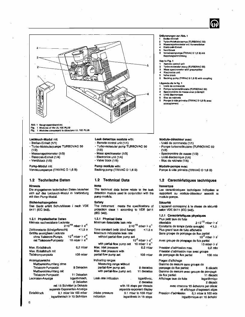
Abb. 1 BaugruppenOberslchl Fig. 1 Modules of the UL 100 PLUS Fig. 1 Modules compos,ant Ie detecteur UL 100 PLUS
LecksuCh·Modul mit • Bedien-Einheit (1/1) • Turbo-Molekularpumpe TURBOVAC 50
(112) • Massenspaktrometer (113) • Elektronik-Einheit (1/4) • Ventilblock (1/5)
Pump-Modul mit VOlVSkuumpumpe (TRIVAC D 1,6 B)
1.2 Technlsche Daten
Hlnwels Die angegebenen technischen Daten beziehen sich auf das Lecksuch-Modul In Verbindung mit dam Pump-Modul.
SlcherheHsangaben Das GarAt erront Schutzklasse I naoh VOE 0411 (lEO 348).
1.2.1 Physlkallsche Daten Kleinste nachweisbare Leckrate
2_10.10 mbar- ,. S·1
Zeitkonstante (blindgefJanscht) < 1,5 S GroBteI anzeigbare Leckrate
ohne Teilstrom-pumps. 10.2 mbar' ,. S·1 mitTeilstrom~Pumpsatz 10 mbar'" S·1
Max. EinlaBdruck Max. EinlaBdruck mit Teilstrompumpsatz
Anzeigebereiche MeBbereichsumfang -ohne Teilstrom-Pumpsatz:
0,2 mbar
100 mbar
80ekaden MeBbereichsumfang mit Teilstrom-Pumpsat2: 11 Oekaden
logarithmisch, 20ekaden
mit 15 Schritten je Dekade separate Exponenten-Anzeige
0,1 mbar bis 100 mbar logarithmisch in 15 Schritten
Leckraten-Anzeige
EinlaBdruck
6
Leak detection module with: - Remote-control unit (1/1) • Turbo-molecular pump TURBOVAC 50
(112) - Mass spectrometer (113) - Electronics unit (1/4) • Valve block (115)
Pump module with: Backing pump CTRIVAC 0 1,6 B)
1.2 Technical Data
Note The technical data below relate to the leak detection module used in conjunction with the pump module.
Safety The instrument meets the specifications of protection class 1 according to VOE 0411 (lEO 348).
1 .• 2.1 Physical Data Minimum detectable leak rate
2.10-10 mbar.l. S·1
Time constant (with blind flange) < 1.5 s Maximum indicatable leak rate
without partial-flow pump set 10-2 mbar' I. S·1
with partial-flow pump set 10 mbar·'. S·1
Max. inlet pressure 0.2 mbar Max. inlet pressure with partial flow pump set 100 mbar
Indicating ranges Measuring range without partial-flow pump set 8 decades
11 decades with partial-flow pump set
Leak rate indication
Intake pressure indication
logarithmic, 2 decades
with 15 steps per decade separate exponent display
0.1 mbar to 100 mbar logarithmic in 15 steps
Erliuterungen zur Abb. 1 1 Bedlen-Elnheit 2 Turbo-Moiekularpumpe (TURBOVAC 50) 3 Massanspaktromater mit VorvarsUirker 4 Elektronlk·Elnhelt 5 Ventltblock 6 Vorvakuumpumpe (TRNAC 0 t.6 B) mit
Kopplungselnrlchtung
Kay to Fig. 1 1 Ramote control unit 2 Turbo-molecular pump (TURBOVAC 50) 3 Mass spectrometer with preamplifier 4 Electronics unit 5 Valve block 6 Backing pump (TRNAC 01,6 B) with coupling
L6gende de la Ilg. 1 1 Unite da commanda 2 Pompe turbomoleculalre (TURBOVAC 50) 3 Spectromatre de masse avec preampll 4 Unite elactronlque 5 Bloc de roblnets 6 Pompa a vide prlmalre {TRIVAC 0 1 ,6 B) avec
accouplement
Module-dirtecteur avec: - Unite de commande (1/1) • Pompe turbomolaculaire (TURBOVAC 50
(1/2) • SpectromOtte de m .... (1/3) - Unite electronique (114) - Bloc de robinets (1/5)
Module-pompa avec: Pompa it vide primalre (TRIVAC 0 1,6 B)
1.2 Caracterlstlques techniques Remarque Les caracteristiques techniques indiquges St
rapportent au module·delecteur associe &
modure·pompe.
Securlte L'appareil correspond it la classe de securitEt solon VDE 0411 (lEO 348).
1.2.1 Oaracterlstlqu .. physiques Plus petit taux de fuite decelable 2.10.10 mbar- I· s' Constanta de temps (bride aveugle) < 1 ,5 ' Plus grand taux de fuite affichable Sans groupe de pompage de flux partiel
10.2 mbar·l· s' Avec groupe de pompage de flux partiel
10 mbar· I· .. Pression d'admission max. 0,2 mb~ Pression d'admission max avec groupe de pompage de flux partiel 1 00 m~
Plages d'affichage Gamme de mesure sans groupe de pompage de flux partlel: 8 decade Gamma de mesure avec groupe de pompage de flux partiel: 11 decade Affichage taux de fuite logarithmiqui
2 decade avec chacune 15 echelons par decac
at aflichi'!le d'exposant sepal Pression d'admission 0,1 mbar it 100mb;
logarithmique en 15 echelor
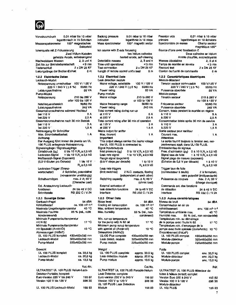
mm ________________________ __ Vorvakuumdruck 0,01 mbar bis 10 mbar
logarithmisch in 15 Schritten Massenspektrometer 180 0 magnetisches
Sektorteld lonenquelle mit Z-Fokussierung
Zwei lridium-Katoden geheizte Anode, selbstreinigend
Nachweisbare Massen 2, 3· und 4 Zeit bis 2ur Betriebsbereitschaft < 3 min TestanschluB 2 x ON 25 KF Leitungslange der Bedien-Einheit 8 m
'1.2.2 Elektrlsche Daten Lecksuch-Modul:
Netzspannung umschaltbar 100 V I '20 V 220 V 1240V (±S %) 50160 Hz
LeistungsaUfnahme 80 VA Pump-Modul:
Netzspannung 210 bis 260 V oder 100 bis 130 V
Netzfrequenzbereich 50/60 Hz Leistungsaufnahme 240 VA
Gesamtstromaufnahme wAhrend Hochlauf bell10V SA bei 220 V 2,5 A
Gesamtstromaufnahme nach 30 min Betrieb bei110V 3A bei220V' 1,5A
Netzausgang fOr SchnQffler Max. Strombelastbarkeit Achtung
1A
Der Ausgang fQhrt immer die jeweils am UL 100 PLUS anliegende Netlspannung.
Signaleingange I SignaJausgange EinlaBdruck (PE) 0 bis 10 V,RL~2,5 kG Leckraten-Signal 1 bis 10 V,RL~2,5 kG MeBbereich-Signal (Exponent) (0,5-V-Stufen pro Dekade) 1 bis 10 V
RL~2,5 kn Leckraten-Trigger (Grenz-wertschatter) 2 SchrieBer, potentiaJfrei
(voneinander unabMngig) SchaJtvermOgen max. 2 A; 60 V
(Ohmsche las1) Ext. Ansteuerung Lecksuch-funktionen 24 bis 48 V DC Schnitts1elle RS 232 C I V.24
1.2.3 Sonstlge Daten Gerausch-PegeJ 54 dBA KOhlluftbedarf ca 100 m3 ·h·' Maximale Umgebungstemperatur 40 °C Maximale Feuchte 85 % (rei., nicht
kondensierand) Minimale Pumpenanlauftemperatur mit N 62 Minimale Pumpenanlauftemperatur mit SpazialOI (Arctic~61) Abmessungen (HxBxl)
17°C
10°C
UL 100 PLUS komplett Lecksuch-Modul Pump-Modul
430X460x250 mm 320)(460x250 mm 225x460x250 mm
Gewicht UL 100 PLUS komplett Lecksuch-Modut Pump-Modu!
ca 33,5 kg ca 20,0 kg ca. 13,5 kg
Kat-Nr. ULTRATEST UL 100 PLUS Helium-LeckDetektor-Portable; komplett Euro-Version 220 V bis 240 V 15582 Version 100 V bis 120 V 896 38
UL 1 00 PLUS Lecksuch-Modul 15583
Backing pressure indication Mass spectrometer
0.01 mbar to 10 mbar logarithmic in 15 steps 180 0 magnetic sector
Ion source with Z-axis focussing two iridium cathodes
heated anode, self-cleaning Detectable masses 2, 3 and 4 Time untit operational < 3 min Test connection 2 x ON 25 KF Length of remote control unifs lead 8 rn
1.2.2 Electrical Data Leak detection module
Mains voltage, selectable 100 V / 120 V 220 V /240 V (±5 %) 50/60 Hz
Power rating 80 VA Pump module
Mains voltage
Mains frequency range Power rating
210 to 260 V or 100 to 130 V
50/60 Hz 240 VA
Total current rating during run-up at110V 5A at 220 V 2.5 A
Total current rating after 30 min of operation at110V 3A at 220 V 1.SA
Mains output for sniffer Max. cuurant Important
1 A
This output always carries the mains voltage the Ul 100 PLUS is connected to.
Signal inputs/outputs In!et pressure (PE) 0 to 10 V,RLi!!2,5 kD Leak rate signal 1 to 10 V,RL~2.5 kD Range signal (exponent) (0.5-V steps per decade)
Leak. rate triggers
1 to 10 V RL~2.S kO
(limit switches) 2 N.C. contacts, floating' (independent of each other)
Switching capacity max. 2 A; 60 V , (ohmic load)
Extemal activation of leak detection functions Interlace
1.2.3 Other Data Noise level COOling air consumption Max. ambient tempera1ure Max. humidity
Min. run-up temperature
241048VDC RS 232 C I V.24
S4dBA ca. 100 rn3 ·h·'
40°C 85 % (rei., non
condensed)
for the pump with N 62 oil Minimum pump runup temperature with special oil (Arctic·oil) Dimensions (HxWxO)
UL 100 Plus complete Leak. detect module Pump module
Weight" UL 100 PLUS complete Leak detection module Pump module
430X460x250 mm 320x460x250 mm 225X46Dx250 mm
approx. 33.5 kg approx. 20.0 kg approx. 13.5 kg
Cat.No. ULTRATEST UL 100 PLUS Portable Helium Leak Detector; complete Euro-version 220 V to 240 V 155 82 Version 100 V to 120 V 896 38 UL100 PLUS Leak Detection Module 15583
Pression vide 0,01 mbar 8 10 mbar primaire [ogarithmique en 15 echelons Spectrometre de masse Champ secteur
magnetique 180 0
Source d'ions avec focalisation Z Deux cathodes an iridium
Anode chauffee, _autonettoyante Masses decelablas 2, 3 et 4 Temps de montee en service <3 min Raccord test 2 x ON 25 KF Cordon de l'unitS de commande 8 m
1.2.2 Caracteristlques electriques Modu!e-detecteur
Tension secteur commutable 220 V /240 V (±5 %)
Puissance absorbee Module-pompa
100 VI120 V 50/60 Hz
80 VA
Tension secteur 210a260V OU1008130V
Frequence secteur 50/60 Hz Puissance absorb8e 240 VA
Consom. totaIe pendant la montee en regime 8110V SA .220V 2,SA
Consommatlon totale apras 30 min de service 8110V 3A a220V 1,SA
Sortie secteur pour renifleur Courant max. AttentIon
1A
La sortie foumit toujours la tension sec. respectivement appJi. dans UL 100 PLUS.
Entrees/sorties de signaux " Pres. d'admission (PE) 0 a 10 V,RL~2.5 kn Signal taux de fuite 1 a 10 V,RL~2,5 kn Signal plage de mesure (exposant) (Echelon de 0,5 V par decade)
Trigger taux de fuile (commutateur a seuils) 2 a fermeture,
sans potentiel (independants) Puissance de coupure max. 2 A; 60 V
(charge ohmique) Commande ext. des fonctions de detection 24 a 48 v DC In1ertece RS 232 C I V.24
1.2.3 Autrea caracteristlquea Niveau de bruit 54 dBA Consommation en air de refroidissement env." 100 m3 ·h·' Temperature ambiants max. 40 °C Humidite max. 85 % (rei., non condensee) Temperature min. au demarrage de la pompa avec I'huile N 62 Temperature min. d'amorcage de la
17°C
pompe avec huiJe speciale (HuileArctic) 10 °C Encombrement (HxLxP)
UL 100 PLUS complet Module-detecteur Module-pompa
Poids UL 100 PLUS complet Module-detecteur Module·pompe
430x460x2.50 mm 320x460x250 mm 225x460x250 mm
env. 33,5 kg env. 20,0 kg env. 13,5 kg
Ret UL TRATEST UL 100 PLUS de1eC1eur de fuites a. helium portatif; complet Version Euro 220 a. 240 V Version 100 V a 120 V Module-d6tecteur UL 100 PLUS
15582 89638
15583
7

--------------____________ mm 1.3 Technlsche Beschrelbung Der UL 100 PLUS dient zum Auffinden von leeks und ermOglicht es, die Leckrate quantitativ zu bestimmen. Die kleinste nachweisb. Helium-Leckrata betragt 2-10.10 mbar-I·S"'.
Der UL 100 PLUS besteht 8US dam Leeksuch-Modu! und dam Pump-Modul.
Oer UL 100 PLUS wird betriebsbereit gelietart. Dabei ist das Lecksuch-Modul auf das Pump-Modul abgestin'\mt und kalibriert. Das Lecksuch-Modul kann auch a1lein zur Auffindung von Leeks an Vakuumanlagen eingesetzt werden. Es muB sichergestellt sein, daB das Lecksuch-Modul nur an einer Stelle der Anlage angeschlossen wird, wo der Druck mit Sicharheit immer kleiner a1s 0,2 mbar ist
Hlnwels Bei alleiniger Verwendung des Lacksuch-Moduls mit sinem externen Vorva!<uum-Pumpsatz
. muB fUr die quantitative Leckraten-Anzeige das Saugvermagen dieses Pumpensatzes berUckslchtlgt werden (slehe Abschnitt 2.4.7). Gegebenenfalls ist das Lecksuch-Modul neu zu kalibrieren. Bel Verwendung des TeilstromPumpsatzes gilt die Kalibrierung Obar den gao. samten erweiterten MeBbereich. .
Nac:h dem Einschalten der Netzspannung baginnt der UL 100 PLUS mit dem automatischen Hochlauf. Dabei wird auf der KombiAnzeiga (4/3) der fortlaufend' erfaBte Vorvakuumdruck Pv (4/22) und der einmal ermittelte EinlaBdruck Pe (4/23) angezeigt Der -UL 100 PLUS ist lecksuchbereit, wenn der Hochlauf beendet ist. Dann schaltet die Kombi-Anzeige (4/3) auf Leckraten-Anzeige urn und zeigt die Betriebsbereitschaft des Gerates an.
Durch kurzes Betatigen der Taste "START" (4/24) wird die Evakuierung eines am UL 100 PLUS angeschlossenen PrDflings beg onnen, gleichzeitig leuchtet die Status-LED (4/1) grun, die Kombi-Anzeige schaltet wieder auf Druckanzeige.
Der fallende EinlaBclruck Pe (PrOfling) wird auf der Skala (4/23) der Kombi-Anzeige (4/3) angezeigt. 1st der EinlaBdruck PE kleiner als 0,2 mbar, erfolgt automatisch ein Umschalten der Kombi-Anzeige (413) von EinlaBdruck PE (4/23) auf Leckraten-Anzeige.
Wird der PrOfling mit Helium besprOht, kann Helium durch die Druckdifferenz durch ein eventuell vomandenes Leck in den PrOfling eindringen. Helium gelangt innerhalb der Ansprechzeit in das Massenspektrometer. Das Massenspektrometer ionisiert die Gas-MolekOIe, trennt sle oach ihrem Masse-zu-LadungsverhaJtnis und fangt die Helium-Ionen (Massanzahl 4) auf. Der Strom, proportional zur Anzahl der Helium-Ionen, die auf den lonenfAnger (3/5) traffen, wird verstarkt und auf der Kombi-Anzeige (4/3) als Leckrate sichtbar gemachl
Zum SelOften des PrOflings muB die Taste "STOP" (4/2) lange gedrOckt werden (mindestens 2 s). Die Status-LED (4/1) leuchtet rot Der Prufling wird hOrbar gaflutet und kann abgenommen werden.
8
1.3 Technical Description The UL 100 PLUS is used for detecting leaks and for quantitative determinations of leak rates. The smallest detectable helium leak rate is 2'10.10 mbar+s·'.
The UL 100 PLUS consists of the leak detection module and the pump module.
The UL 100 PLUS is supplied ready for ope· ration, with the leak detection module matched to the pump module and Calibrated. The leak
. detection module may be used individually for detecting leaks in vacuum systems. In this case, make sure that the leak detection module is connected to a point in the system where the pressure will certainly always be less than 0.2 mbar.
Note When using the leak detection module alone with-an external backing pump set, the pumping speed of this set must be taken into account for the quantitative leak rate indications (see Section 2.4.7). If necessary, the leak detection module must be recalibrated. If the partial·flow pump set is used, the UL 100 PLUS's calibration remains valid over the entire extended pressure range.
After sWitching on the mains power, automatic run-up 01 the UL 100 PLUS starts. The ·continuously monitored backing pressure Pv (4/22) and the once determined intake pressure PE (4/23) are shown on the combined indicator (4/3). The UL 100 PLUS is ready for leak detection once the UL 100 PLUS has run up. Then the combined indicator (4/3) switches over to leak rate indication, showing thai the UL 100 PLUS is ready for operation.
By briefly depressing the "START" pushbutton (4/24), evacuation of a test object connected to the UL 100 PLUS is started. At the same time, the status LED (4/1) lights up green, and the combined indicator changes back to pressure indication.
The falling intake pressure Pe (test object) is shown on the scale (4/23) of the combined indicator (4/3). Once the intake pressure PE drops below 0.2 mbar, the combined indicator (4/3) automatically changes over from intake pressure PE (4/23) to leak rate indication.
When the test object is sprayed with helium, the helium will, owing to the pressure difference, enter the test object through any leak. The helium. reaches the mass spectrometer within the response time. The mass spectrometer ionizes the gas molecules, separates them according to their mass-to·charge ratio and collects the helium ions (mass number 4). The current, whfch is proportional to the number of helium ions arriving at the ion collector (3/5), is amplified and shown on the combined indicator (4/3) as the le_ak rate.
To vent the test object, the "STOP" pushbutton (4/2) must be depressed for at least 2 s. The status LED (411) then turns red and the test object is audibly vented, whereupon it can be disconnected.
. 1.3 Description technique Le detectaur UL 100 PLUS permet non seu[ement la detection de fuites mais egalement la determination quantitative de leurs taux. Le plus petit taux de fuite d'helium decelable sa monte a 2'10·'0 mbar+s-';
Le detecteur UL 100 PLUS se compose de deux modules, [e module-detecteur et Ie module-pompe.
II est pret a fonctionner a la livraison et Ie module-detecteur est adapts au module-pompe et calibre. II est possible d'utiliser ssparement Ie module-detecteur pour detecter des fuites sur des installations a vide. II faut alors s'assurer que ce module soit raccords a un endroit de I'installation ou la pression reste absolument inferieure a 0,2 mbar.
Remarque . Lorsque Ie module-detecteur est employe seul avec un groupe de pompage primaire externe, iI faut tenir compte du debit-volume de ce groupe pour I'affichage quantitatif du taux de fuite (voir section 2.4.7). II est eventuellement necessaire de recalibrer Ie module-detecteur. 5i I'on utilise cependant Ie groupe de pompage de flux partiel, Ie Calibrage reste valable pour toute la gamme etendue des pressions.
La premiere operation de UL 100 PLUS apres sa mise en circuit est la montee en .regime automatique. La pression du vide primaire Pv (4/22) et la pression d'admission PE (4/23) sont indiquees sur I'affichage combine (4/3). La detection peut commencer quand la montee en regime-est terminee. L'affichage combine (4/3) commute alers sur affichage de taux de fuile et montre ainsi la disponibilite de I'apparei!.
L'evacuation d'une piece raccordee au detecteur UL 100 PLUS est amorcee en appuyant brievement sur la touche "START" (4/24). L'affichage d'etat vert (4/1) s'anume simultanement, I'affichage combine revient sur affichage de pression.
La pression d'admission decroissante PE (piece) est indiquee sur I'echella (4/23) de I'affichage combine (4/3). Lorsque cette pression d'admission PE devient infeneure a 0,2 mb81 I'affichage combine (4/3) revient auto· matiquement sur affichage de tau'x de fuite.
La piece est ensuite aSpergee avec de I'helium Si la piece presente une fuite, I'helium peut ) penetrer grAce ill la difference des press ions Ce gaz arrive dans Ie spectrometre de masSE en I'espace du temps de reponse. Le spectra metre de masse ionise les molecules du g82 les separe selon leur rapport masse/charge e capte les ions helium (masse 4). Le couran ionique proportionnel au nombre d'ions heliun arrivant sur Ie collecteur d'lons (3/5) est am plifia et represente sur l'afflChage combine (4/3 en tant que taux de fuite.
La remise a I'air de la piece s'effectue par un longue pression sur la touche "STOP" (4/': (au mains pendant 2 s). L'affichage d'eU rouge (4/1) s'allume, la remise a I'air de I piece se manifeste de fal;on audible. La, piec paut etre ensuite retiree.
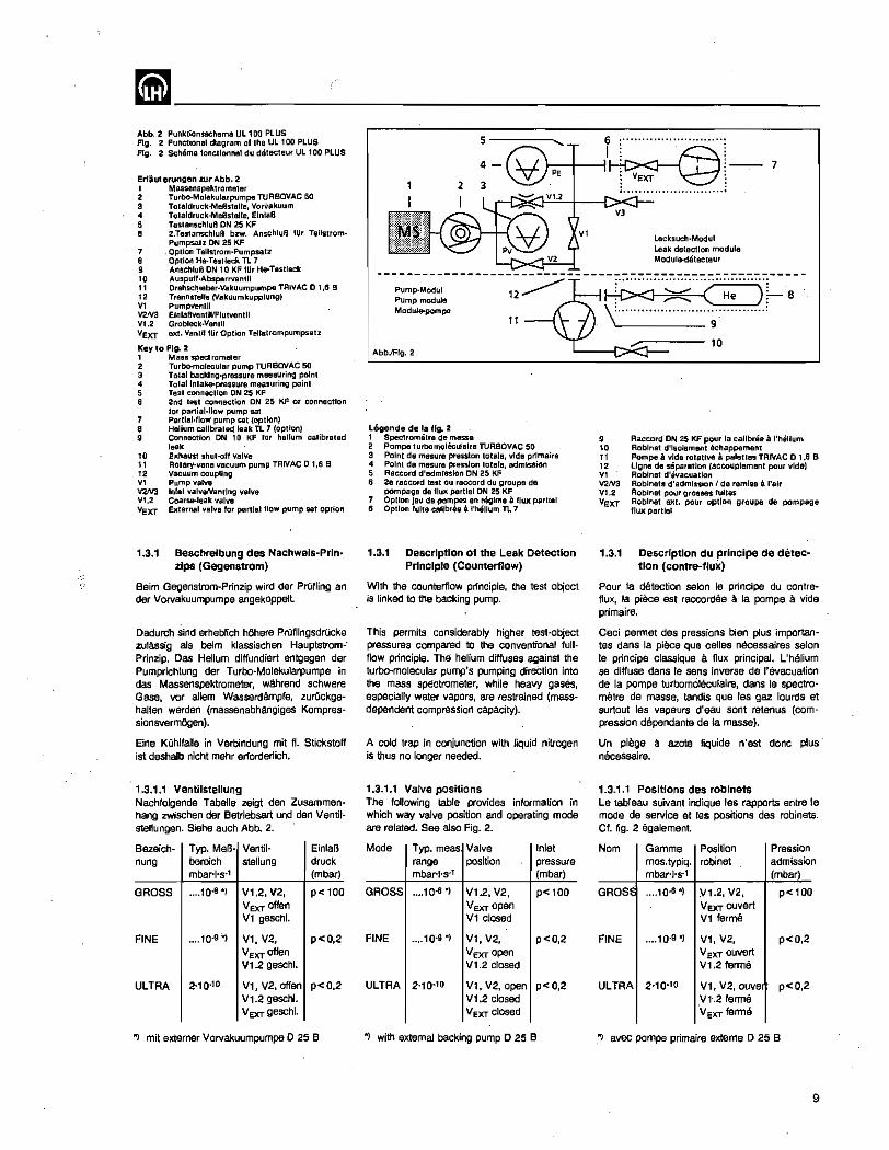
mm ________________________ __ Abb. 2 Funklionsschema UL 1 DO PLUS Fig. 2 Functional diagram of Iha UL 1 00 PLUS Fig. 2 Schema loncllonnal du detecteuf UL 100 PLUS
Erliuterungen zur Abb. 2 1 MaS5enspeklromaler 2 Turbo·Molekularpumpe TURBOVAC 50 3 Tolaldruck·MeBslelle, VOrVakuum " Tolaldruck·MeBslelle, Elnla8 5 Testanschlu8 ON 25 KF 6 2.Tes1anschluB bzw. AnschluB IUr Teilstrom·
Pumpsalz ON 25 KF 7 Oplion TeUstrom·Pumpsatz 8 Option He·Testleek TL 7 9 AnschluB ON 10 KF lOr He-Teslleck 10 Auspull·Absparrventll 11 Drehsc~leber·Vakuumpumpe TRIVAC 0 1,6 B 12 Trenns!e"e (Vakuumkupplung) V, PumpvenUI V2N3 ElnlallVenlillFlulvenlli Vl.2 Grobleck·Venlil VEXT ext. Ventn llir Option Tellslrompumpsalz
Key to FIg. 2 1 Mass spectrometer 2 Turbo-molecular pump TlJRBOVAC 50 3 Total backing-pressure measuring pOint 4 TOlallntake-pressure measuring point 5 Test connection ON 25 KF 6 2nd te5t connection ON 25 KF or connection
lor partlal·liow pump sat 7 Partlal·ltow pump set (option) 8 Helium calibrated leak TL 7 (opUon) 9 Connection ON 10 KF for helium calibrated
leak 10 Exhaust shut-oll valve 1 t Rotary·vane vacuum pump TRIVAC 0 1,6 B 12 Vacuum coupling VI Pump valve V2JV3 Inlat valveI'Vent!ng valve VI.2 Coarse-leak valve VExr Extarnal valve lor partlaillow pump set option
1.3.1 Beschrelbung des Nachwels-Prlnzips (Gegenstrom)
Beim Gegenstrom-Prinzip wird der Prufling an der Vorvakuumpumpe angekoppelt
Dadurcl1 sind erheblich hOhere PrOflingsdrOcke zulAssig als beim klassischen Hauptstrom-' Prinzip. Oas Helium diffundiert entgegen der Pumprichtung der Turbo-Molekularpumpe in das Massenspektrometer, wahrend schwere Gase, var aHem Wasserdflmpfe, zurOckgehalten werden (massenabhangiges Kompressionsvermogen).
Eine KOhlfaUe in Verbindung mit fl. Stickstoff ist deshalb nicht mehr erlorderlich.
1.3.1.1 Ventilstellung Nachfolgende Tabella zeigt den Zusammenhang zwischen der Betriebsart und den Ventilstell un gen. Siehe auch Abb. 2.
Bezeich- Typ. MeB· Ventil- Einlafl nung bereich stellung druck
mbar-I·s·l (mbar)
GROSS .... 10.6 *) V1.2, V2, p< 100 VExr offen V1 geschl.
FINE .... 10·9'*) V1, V2, p<O,2 VExr offen V1.2 geschl.
ULTRA 2'10.10 V1, V2, offen p<0.2 V1.2 geschl. VExr geschl.
, mit extemer Vorvakuumpumpe 0 25 B
Pump.Modul Pump module Module-pompa
AbbJFlg.2
Legenda de la fig. 2 I Spectrometre de masse
5
11
2 Pompa lurbomoleculalre TURSOVAC 50 3 Polnl da mesure pression tolale, vida prlmaire 4 Point de mesura pression totale, admission 5 Raccord d'admisslon ON 25 KF 6 2e raccord tasl au raccord du groupa de
pompaga de flux partiel ON 25 KF 7 Oplion jeu da pomj3fl en regime 8. flux partial 8 Option tulle caJibree! I'helium TL 7
1.3.1 Description of the Leak Detection PrinCiple (Counterflow)
With the counterflow principle, the test object is linked to the backing pump.
This permits considerably higher test-object pressures compared to the conventional full· flow principle. The helium diffuses against the turbo-molecular pump's pumping direction into the mass spectrometer, while heavy gases, especially water vapors, are restrained (massdependent compression capacity).
A cold trap in conjunction with liquid nitrogen is thus no longer needed.
1.3.1.1 Valve positions The following table provides information in which way valve position and operating mode are related. See also Fig. 2.
Mode Typ. meas Valve Inlet range position pressure mbar'j's-T (mbar)
GROSS .... 10-6*) V12, V2. p< 100 VExr open V1 closed
FINE .... 10.9 ") V1, V2, p<O,2 VExr open V1.2 closed
ULTRA 2'10-10 V1, V2, open p<O,2 V1.2 closed V Exr closed
·1 with extemal backing pump 0 25 B
-- 7
Lecksuch·Modul Leak detection module Module·detacteur
~''';;::'''(~~'''''/-- 8 \ ....................... ~ ............ .
9 10 11 12 V, V2N3 VI.2 VeXT
10
Raccord ON 25 KF pour la callbree a t'Mllum Roblnat d'isolement Achappement Pompe a vida rotative a patelles TRIVAC 0 1.6 B lIgne de separatIon (accouplement pour vide) Roblnal d'evacuetion Roblnels d'admlssion I de remise a I'alr Roblnel pour grosses lultes Robinet exl. pour option groupe de pompage fluxpartlel
1,3,1 Description du principe de detec-tion (contre-flux)
Pour la detection salon Ie principe du contreflux, la piece est raccordee a la pompe a vide primaire.
Ceci permet des pressions bien plus importantes dans la piece que celles necessaires salon Ie principe classique a flux principal. L'helium se diffuse dans Ie sens inverse de I'evacuation de la pompe turbomolsculaire, dans Ie spectrametre de masse, tandis que les gaz lourds et surtout les vapeurs d'eau sont retenus (compression dependante de la masse).
Un piege a azote liquide n'est done plus necessaire.
1.3.1.1 Positions des robinets Le tableau suivant indique les rapports entre Ie mode de service et les positions des robinets. Cf. fig. 2 egalement.
Nom Gamme Position Pression mes.typiq. robinet admission mbar+s-1 (mbar)
GROS .... 10-6 *) V1.2, V2, p<100 VEXT ouvert V1 ferme
FINE .. .. 10.9 *) V1, V2, p<0,2 VExr ouvert V1.2 ferme
ULTRA 2'10-10 V1. V2, ouve p<0,2 V1".2 ferms VExr 1erme
, avec pompe primaire externe D 25 8
9
--------------------------~ 1.3.2 Vorvakuumpumpe Die VOlVakuumpumpe erzeugt aus dam in den Leck-Detektor flieBenden Helium-Strom ainen proportionalen Helium-Druck. Dabei wird das stabile Helium-SaugvermOgen dieser Pumpa ausgenutzt. Seine GroBe bestimmt zusammen mit der Kompression der Turbo-Molekularpumpa die Empfin,dlichkeit der Anordnung.
Als Vorvakuumpumpe ist im UL 100 PLUS aine Drehschieber-Pumpe TAIVAC 0 , ,6 B eingebaut. Aile Daten und Angaben kOnnen der Gebrauchsanweisung GA 01.200 entnommen wEirden.
1.3.3 Turbo-Molekularpumpe Die Turbo-Molekularpumpe erzeugt aus dam Helium-Druck im Vorvakuum den HeliumDruck im Massenspektrometer, der dert dann nachgewiesen wird, Dabei wird ihr stabiles Kompressionsverm6gen fOr Helium 8u5genutzt. Seine GrOBe bestimmt zusammen mit dem SaugvermOgen der Vorvakuumpumpe die Empfindlichkeit der Anordnung,
Die Turbo-Molekularpumpe is~ aine TURBOVAC 50, Aile Daten und Angaben kennen der GA 05.100 entnommen werden.
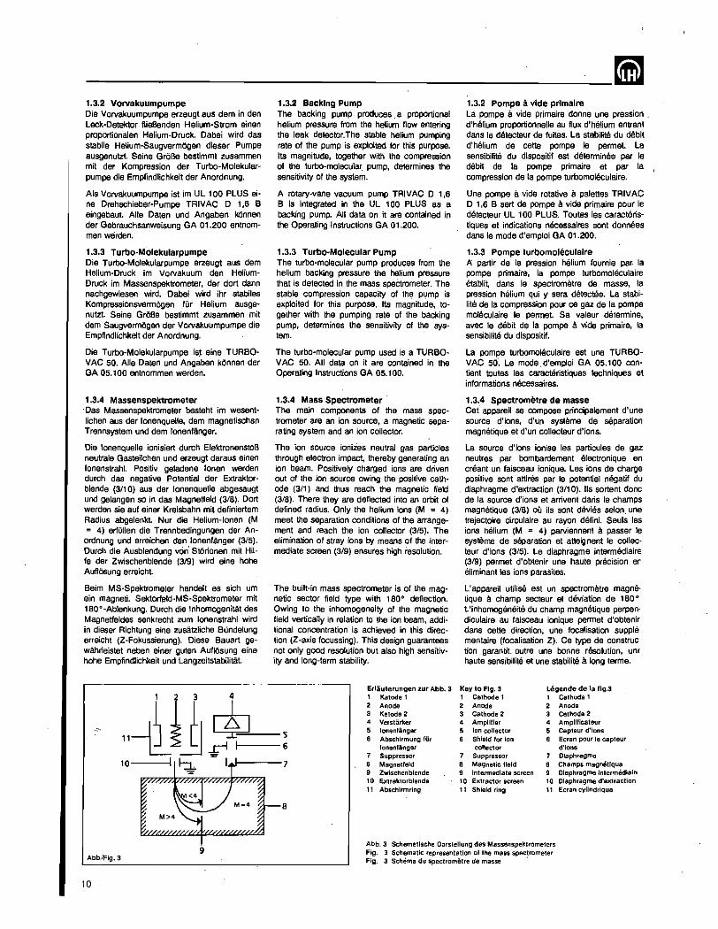
1.3.4 Massenspektrometer . Das Massenspektrometer besteht im wasentlichen aus der lonenquelle, dem magnetischen Trennsystem und dem 10nenfAnger.
Die lonenquelle ionisiert durch ElektronenstoB neutrale Gasteilchen und erzeugt daraus einen lonenstrahl. Positiv geladene lonen werden durch das negative Potential der Extraktorblende (3/10) aus der lonenquelle abgesaugt und gelangen so in das Magnetfald (3/8). Dart werden sie auf einer Kreisbahn mit definiertam Radius abgelenkt. Nur die Helium-Ionen (M = 4) erfullen die Trennbedingungen der An
ordnung und erreichen den lonenfanger (3/5). Durch die Ausblendung vOn' SIOrionan mit Hilfe der Zwischenblende (319) wird eine hohe AufiOsung erreicht.
Beim MS-Spektrometer handelt es sich um ein magneti. Sektorfald-MS-Spektrometer mit 180 0 -Ablenkung. DUrch die Inhomogenitat des Magnetfeldes senkrecht zum lonenstrahl wird in dieser Richtung eine zusatzliche Bundelung erreicht (Z -Fokussierung). Diese Bauart gewahrleistet neben einer guten AuflOsung eine hohe Empfindlichkeit und LangzeitstabilitAt.
10
1.3.2 Backing Pump The backing pump produces a proportional helium pressure from the helium flow entering the leak detector.The stable helium pumping rate of the pump is exploited for this purpose, Its magnitude, together with the compression of the turbo-molecular. pump, determines the sensitivity of the system.
A rotary-vane vacuum pump TRIVAC D 1,6 B is integrated in the UL 100 PLUS as a backing pump. AU data on it are contained in the Operating Instructions GA 01.200.
1.3.3 Turbo·Molecular Pump The turbo-molecular pump produces from the helium backing pressure the helium pressure that is detected in the mass spectrometer. The stable compression capacity of the pump is exploited for this purpose. Its magnitude, together with the pumping rate of the backing pump, determines the sensitivity of the system.
The turbo-molecular pump used is a TURBOVAC 50, All data on it are contained in the Operating Instructions GA 05.100.
1.3.4 Mass Spectrometer The main components of the mass spectrometer are an ion source, a magnetic separating system and an ion collector.
The ion source ionizes neutral gas particles through electron impact, thereby generating an ion beam. Positively charged ions are driven out of the ion source owing the positive cath~e (3/1) and thus reach the magnetic field (3/8). There they are deflected into an orbit of defined radius., Only the helium ions (M = 4) meet the separation conditions of the arrangement and reach the ion collector (3/5). The elimination of stray ions by means of the intermediate screen (3/9) ensures high resolution.
The built-in mass spectrometer is of the magnetic sector field type with 180° deflection, Owing to the inhomogeneity of the magnetic field vertically in relation to the ion beam, additional concentration is achieved in this direction (Z-axis focussing). This design guarantees not only gOOd resolution but also high sensitivity and long-term stability.
Erlauterungen zur Abb. 3 1 Katode 1 2 Anode 3 Katode 2 4 Verstarker
5 • lonenlanger , Abschirmung fUr 6 lonenf.iinger
7 Suppressor 7 , Magnelfeld
9 Zwlschenblende 10 EKtraktorblende 11 Abschlrmring
1.3.2 Pompe a vide prlmalre La pompe a vide primaire donne une pression . d'hSlium proportionnelle au flux d'hSlium entrant dans Ie detecteur de fuites. La stabilite du debit d'helium de cette pompe Ie permet La sensibilite du dispositif est determinee par Ie debit de la pompe primaire at par la compression de la pompe turbomoleculaire.
Une pompe a vide rotative a palettes TRIVAC D 1,6 B sert de pompe a vide primaire pour Ie detecteur UL 100 PLUS. Toutes les caractEiristiquas et indications necessaires sont donnees dans Ie mode d'emploi GA 01.200.
1.3,3 Pompe turbomoleculalre A partir de la pression helium fournie par: la pompe primaire, la pompe turbomoleculaire etablit, dans Ie spectrometre de masse, la pression helium qui y sera detectEie. La stabilite de la compression pour ce gaz de fa pompe mo!eculaire Ie permet. Sa valeur determine, avec Ie debit de la pompa a vide primaire, la sensibilite du dispositif.
La pompe turbomoleculalre est une TURBOVAC 50". Le mode.d'emploi GA 05.100 contient toutes les caracteristiques techniques et informations necessaires.
1.3,4 Spectrometre de masse Cet appareil Se compose principalement d'une source d'ions, d'un systeme de separation magnetique et d'un collecteur d'ions.
La source d'ions ionise les particules de 9az neutres par bombardement electronique en creant un faisceau ionique. Les ions de charge positive sont attires par Ie potentiel negatif du diaphragme d'extraction (3/10). lis sortent done de fa source d'ions at arrivent dans Ie champs magnetique (3/8) au its sont devies selon. une trajectoire circulaire au rayon defini. Seuls les ions heUum (M = 4) parviennent a passer Ie systems de separation et atteignent Ie callec· teur d'ions (3/5). Le diaphragme intermediaire (319) permet d'obtenir une haute precision er eliminant les ions paraSites.
l'appareil utilise est un spectrometre magna· tique a champ secteur et deviation de 180 ° L'inhomogenane du champ magnetique perpen· diculaire au faisceau ionique permet d'obtenir dans cette direction, une focalisation supple mentaire (focalisation Z). Ce type de construc tion garantit outre una bonne r9s0lution, UOf
haute sensibilite et une stabilite a long terme.
Key to Fig. 3 Legende de la flg.3 1 Cathode 1 1 Cathode 1 2 Anode 2 Anode 3 Cathode 2 3 Cathode 2 4 AmpUllar 4 AmpJJficateur
• Ion collector • Capleur d·ions , Shield for ion , Ecran pour Ie capteur collector d'ions
7 Suppressor 7 Olaphragme , Magnetic Ilerd Champs magnetJque 9 Intermediate screen Olaphragme Intermedlairl 10 Extractor screen ,. Olaphragme d·extraction 11 Shield ring 11 Ecran cyJlndrique
M=4 8
Abb.lFlg.3
10
9 Abb. 3 Schematlsche Darstellung des Massenspektrometers Fig. 3 Schematic representation of the mass spectrometer Fig. 3 Schema du spectrometre de masse .
~-------------------------1.3.5 lonenqueUe Die aus der Katode (3/1) oder (3/3) austretenden Elaktronen werden von der positiven Anode (3/2) angezogen. Sis treffen aber nicht 50-fort auf die Anode, sondern pandaln oft zwischen der Katode und dem Abschirmring (3111), bis sie schlieBlich an die Orahtwendel . der Anode gelangen. Auf diesem Wage ionisieren die Etektronen ,Gasatome durch Sto/3. Die positiven Gasionen werden durch die Extraktorblende (3/10) aus dam Anodenraum gazogen.
Zur Vermeidung von polymerisierten Kohlenwasserstoffablagerungen (isolierende Schichten, die die Empfindlichkeit beeintrachtigen kOnnen) 'yVird die Anode sta,ndig geheizt.
Die Katoden bestehen aus Iridiumband, das mit Thoriumoxid beschichtet ist. Wagen ihres Thoriumbelages arbeiten diese Iridium-GIOhfaclen mit einer viel niedrigeren Temperatur als Wolfram-GIOhfaden und haben eine ausgezeichnete Widerstandsfahigkeit (Durchbrennsichemeit) gegen VersprOdung, O2, H20-Dampf und KW-Stoffe.
Achtung Halogene oder halogenhaltige Substanzen k6nnen unter Umstanden die Lebensdauer der Katoden ungOnstig beeinflussen.
1.3.6 lonenfanger und Verstlrker Die positiven Helium-Ionen, die auf den lonenfanger (3/5) treffen, erzeugen im hochohmigen Eingang des Verstarkers einen Strom. Nach Verstarkung und Wandlung erscheint das Signal auf der Kombi-Anzeige (4/3) als Leckrateo
1.3.5 Ion Source The electrons emerging from the cathode (3/1) or (3/3) are attracted by the positive anode (3/2). However, they do not immediately reach the anode, but travel to and fro between the cathode and the shield (3/11) until finally reaching the wire spiral of the anode. In this path the electrons ionize gas atoms through impact. The positive gas ions are extracted from the anode space by the extractor screen (3/10).
The anode is constantly heated to prevent polymerized hydrocarbon deposits (insulating layers that may "impair the sensitivity).
The cathodes consist of iridium tape coated with thorium oxide. Owing to this thorium coating, the iridium filaments operate at a much lower temperature than tungsten ones and possess excellent resistance (burnout resistance) to embrittlement by oxygen, water vapor and hydrocarbons.
Important Halogens or halogen-containing substances may adversely affect the service life of the cathodes.
1.3.6 Ion Collector and Amplifier The positive helium ions arriving at the ion collector (3/5) produce a voltage at the highimpedance input of the amplifier. After pastamplification and conversion, the signal appears on the combined indicator (4/3) as the leak rate.
1.3.5 Source d'ions Les electrons sortant de la cathode (3/1) ou (313) sont attires par I'anode positive (3/2). lis ne parviennent pas immediatement a I'anode mais oscillent fn§quemment entre la cathode et I'ooran cylindrique (3/11) jusqu'a ce qu'ils atteignent enfin Ie filament spirale de I'anode. Les electrons ionisent de cette fa~on las atomes de gaz par collision. Les ions de gaz positifs sont retires de la zone de I'anode par [e diaphragme extracteur (3/10).
L'anode est chauffee constamment atin d'eviter les depOts d'hydrocatbures polymerises (couche isolante nuisant a. la sensibilit8).
Les cathodes sont composees de bandas d'jridium racouvertes d'une couche de thorine qui autorisa une temperature nettement inferieure a celie des filaments an tungstene et res rend tres resistants (imbrOlab[es) a la porasite, a I'oxygena, a la vapeur d'eau et aux hydrocarbures.
Attention Les halogenes au substances en contenant peuvent rectuire dans certains cas la duree de vie des cathodes.
1.3.6 Collectaur d'ions at ampllflcateur Les ions helium pasitifs arrivant au collecteur (3/5) creent une tension sur "entree fortement ohmique de I'amplificateur. Le signal, converti at amplifie, apparait, sur I'affichage combine (4/3) en indiquant Ie taux de fuite.
11
___________________________ mm 1.4 Ausstaltung
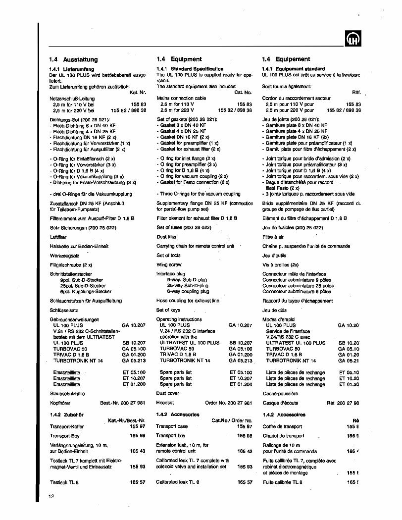
1.4.1 Lleferumfang Der UL 100 PLUS wire! betriebsbereit· 8usgeliefert Zurn Lieferumfang gshOren zusMzlich:
Kat Nr. NetzanschluB-Leitung
2,5 m fOr 110 V bei 2,5 m fUr 220 V bei
15583 15582/89638
Dichtungs-Set (200 28 021): - Flach-Dichtung 6 x ON 40 KF - Flach-Dichtung 4 x ON 25 KF • Flachdichtung DN 16 KF (2 x) - Flachdichtung fOr VOJVerstarker (1 x) - Flachdichtung fOr Auspuffilter (2 x)
- D-Ring fOr EinlaBflansch (2 x) - C-Ring fOr Vorverstarker (3 x) • O·Ring fOr D 1.6 B (4 x) - C-Ring fOr Vakuumkupplung (2 x) - Dichtring fOr Festo-Verschraubung (2 x)
- drei O-Ringe fOr die Vakuumkupplung
Zusatzflansch ON 25 KF (AnschluB far Teilstrom-Pumpsalz)
Filterelement zurn Auspuff-Filter 0 1.6 B
Satz Sicherungen (200 28 022)
Luftfilter
Halskette zur Bedien-Einheit
Werkzeugsatz
FIOgelschraube (2 x)
Schnittstellenstecker Spol. Sub-D-Stecker 25pol. Sub·D·Stecker 6pol. Kupplungs-Stecker
Schlauchstutzen fOr Auspuffleitung
SchlOsselsatz
Gebrauchsanweisungen UL 100 PLUS GA 10.207 V .241 AS 232 C~Schnittstenen~ betrieb mtt dem ULTRATEST UL 100 PLUS TURBOVAC50 TRIVAC D 1,6 B TURBOTRONIK NT 14
Ersatzteilliste Ersatzteilliste Ersatzteilliste
StaubschutzhOlle
KopfhOrer
1.4.2 Zubeh6r
SB 10.207 GA 05.100 GA 01.200 GA 05.213
IT 05.100 ET 10.207 IT 01.200
Kat.·NrJBest.-Nr. Transport·Koffer 155 97
Transport~Boy 155 98
Verlangerungsleitung, 10m, zur Bedien-Einheit 165 43
Testleck TL 7 komplett mit Elektro~ magnet-Ventil und Einbausatz 155 93
Testleck TL 8 165 57
12
1.4 Equipment
1.4.1 Standard Specification The UL 100 PLUS is supplied ready for operation. The standard equipment also includes:
Cat No. Mains connection cable
2.5 m for 110 V 2.5 m for 220 V
15583 15582/89638
Set of gaskets (200 28 021 ~ ~ Gasket 6 x ON 40 KF - Gasket 4 x ON 25 KF • Gasket DN 16 KF (2 x) • Gasket for preamplffier (1 x) - Gasket for exhaust filter (2 x)
- a ring for inlet flange (2 x) · 0 ring for preemplffier (3 x) ·0 ring forD 1.6 B (4 x) ~ 0 ring for vacuum coupling (2 x) - Gasket for Festa connection (2 x)
- Three O-rings for the vacuum coupling
SupplementalY flange ON 25 KF (connection for partial-flow pump set)
Filter element for exhaust filter 0 , ,6 B
Set of fuses (200 28 022)
Dust filter
Carrying chain for remote control unit
Set of tools
Wing screw
Interface plug 9-way. Sub-o-plug 25~way Sub~D-plug
6-way coupling plug
Hose coupling for exhaust line
Set of keys
Operating instructions UL 100 PLUS V.24 I RS 232 C interface operation with the ULTRATEST UL 100 PLUS TURBOVAC50 TRIVAC D 1,6 B TURBOTRONIK NT 14
Spare parts list Spare parts list Spare parts list
GA 10.207
SB 10.207 GA 05.100 GA 01.200 GA 05.213
IT 05.100 IT 10.207 IT 01.200
Dust cover
Headset Order No. 200 27 981
1.4.2 Accessories Cat.NoJ Order No.
Transport case 15597
Transport bey 155 98
Extension lead, 10m, for remote control unit 165 43
Calibrated leak TL 7 complete with solenoid valve and installation set 15593
Calibrated leak TL B 16557
1.4 Equlpement
1.4.1 Equlpement standard UL 100 PLUS est prAt au service a la livraison:
Sont foumis egalement ReI.
Cordon du raccordement secteur 2,5 m pour-110V pour 15583 2,5 m pour 220 V pour 155 82 , 896 38
Jeu de joints (200 28 021): - Garniture plate 6 x ON 40 KF - Garniture plate 4 x ON 25 KF • Garnilure plate DN 16 KF (2x) - Garniture plate pour preamplificateur (1 x) • Garnit plate pour filtre d'echappement (2 x)
- Joint torique pour bride d'admission (2 x) - Joint torique pour pr8amplificateur (3 x) - Joint torique pour 0 1,6 B (4 x) - Joint torique pour raccordem. sous vide (2 x) - Begue d'etancMite pour raccord
filetil Festa (2 x) - 3 jOints toriques p. raccordement sous vide
Bride supplementaire ON 25 KF (raccord dl. groupe de pompage de flux partiel)
Eleme.nt du fittre d'eohappement 0 1,6 B
Jeu de fusibles (200 28 022)
Filtre a air
Chaine p. suspendre l'unitS de commande
Jeu d'outils
Vis a oreilles (2x)
Connecteur mAle de"I'interface Connecteur subminiature 9 pOles Connecteur subminiature 25 pOles Connecteur subminiature 6 pOles
Raccord du tuYau d'eohappement
Jeu de cles
Modes d'emploi UL 100 PLUS Service de I'interface V.24/RS 232 C avec ULTRATEST UL 100 PLUS TURBOVAC50 TRIVAC D 1,6 B TURBOTRONIK NT 14
Liste de pieces de rechange Liste de pieces de rechange Liste de pieces de rechange
Cache-poussiere
GA 10.20'
SB 10.20' GA 05.100 GA 01.20 GA 05.21
ET 05.10 ET 10.20 IT 01.20
Casque d'ecoute Ro!. 200 27 98
1.4.2 Accessolres
Coffrs de transport
Chariot de transport
Rallonge de 10 m pour I'unite de commands
Fuite callibree TL 7, complete avec robinet electromagnetique et pieces de montage
Fuite calibres TL 8
Re 1559
1559
165.!
155 !
1651
~ Testleck TL 4-6 15580
Heliuffi-$chnOffler aUICKTEST aT 100 1559'
Helium-Standard-SchnOffler ST lOa 15590
SchnQffelleitung zum aUICKTEST, 5m 15577
SchnOffelieilung zurn aUICKTEST, 20m 15576
Teitstrom-Pumpsatz 16544
Ersatz-Ionenquelle 165 A.
Sonderzubehor Ausputfschlauch 5.6 x 2,75 pvc 12802 158
Arctic 01 (Flasche mit 1 I) 20028 181
Hlnwels Zum SelOften des UL 100 PLUS mit anderen Gasen a1s Umgebungsluft, kann das Sinterfiltar am Ventilblock (BelOftungsventil V3) gegen eine Schlauchverschraubung mit Schlauch ausgetauscht werden. 8enOtigt wird: Schlauchverschraubung M 5 fOr Schlauch 5 x 1 200 23 010 Schlauch 5 x 1 (MetalWare) 128 20 140
. Calibrated leak TL 4-6 15580
Helium Sample Probe aUICKTEST aT 100 1559.
Helium Standard Sample Probe ST lOa 15590
Sniffer tine for aUICKTEST, 5 m 15577
Sniffer line for aUICKTEST, 20 m 15576
Partial-flow pump set 16544
Spare ion source 16504
Special accB.ssories Exhaust tubing 5.5 x 2.75 PVC 12802158
Arctic oil (bottle with 1 I) 200 28181
"'Ole For venting of the UL 100 PLUS with gases other than air the sinter filter in the valve block (venting valve V3) may be exchanged for a screw-on hose coupling with hose. For this the following parts are required: Screw-on hose coupling M 5 for hose 5 x 1 Hose 5 x 1 (specify length)
200 23 010 12820140
Fuite calibree TL 4·6 15580
Renifleur helium aUICKTEST aT 100 1559'
Renifleur helium standard ST lOa 15590
Conduite du renifleur aUICKTEST, 5 m 15577
Conduits du renifleur aUICKTEST, 20 m 15576
Jeu de parT)pas en regime a flux partiel 16544
Source d'ions de rechange 165 O'
Accessoire special Tuyau d'echappement 5,5 x 2,75 PCV 12802 158 Huile Artie (bouteille avec 1 I) 20028 181
Remarque Pour remettre UL 100 PLUS a l'atmospMre avec d'autres gaz que I'air ambiant, il est possible de remplacer Ie fiJtre fritte du bloc de robinets (robinet V3) contre un raccord a vis 8quipe d'un tuyau. Sont necessaires: Raccord a vis M 5 pour Tuyau 5 x, Tuyau 5 x 1 (au metre)
200 23 010 12820 140
13
-...,..-____________ lil 2 Bedlenung und Betrieb
2.1 Aufstellen des UL 100 PLUS
2.1.1 Uberslcht der Bedlen- und Anzelgeelemente
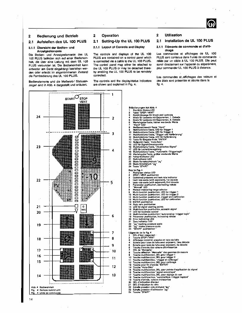
Die Badien- und Anzeigeelemente des Ul 100 PLUS befinden sich auf einer Bedieneinheit, die Ober aine Leitung mit dam UL 100 PLUS verbunden' 1st Die Bedieneinheit kann entweder am Gerat eingeMngt betrieben werden oder erlaubt im abgenommenen Zustand die Fembedienung des UL 100 PLUS.
Badienelemente und die MeBwert-1 Statusanzeigen sind in Abb. 4 dargestellt und eriautert .
24
23
22
21
20
19
18
17
16
15
14
........................................
2 Operation 2 Utilisation
2.1 Setting-Up the UL 100 PLUS
2.1.1 Layout of Controls and Display
2.1 Installation de UL 100 PLUS
2.1.1 Elements de commande at d'affl-chage
The controls and displays of the UL 100 PLUS are contained on a control panel which is connected via a cable to the UL 100 PLUS. The control panel may either be attached to the UL 100 PLUS or may be detached thereby enabling the UL 100 PLUS to be remotely controlled.
Les commandes at affichages de UL 100 PLUS sont contenus dans I'unite de commande reliee par un cable a. UL 100 PLUS. Ene paut sarvir directement sur I'appareil au separement, pour commander UL 100 PLUS a distance.
Les commandes at ,affichagas des valeurs at das stats sont presentes at decrits dans la The controls and the display/status indicators
are shown and explained in Fig. 4. fig. 4.
2
3
4
5
6
7
8
9
10
11
12
13
ErUiuterungen zur Abb. 4 1 Rot·Grlln Status·LED 2 Tasle"STOP/VENT" 3 Koml)l·Anzeige ttlr Druck und Leckrale 4 Skala ttlr Leckrate mil Exponenten, 1. Dekade 5 Skala Illr Leckrale mil Exponenten, 2. Dekade 6 Wertelngabe·Taste, klelner werdande Werle 7 ':Hand" LED 8 MeBberelchswahl·Taste "Hand" 9 MulllIunktlons·Tasle, LED Illr Trigger 1 10 Multllunklions.Tasle, 'LED lilt .Trlgger 2 11 Multlfunklions.Tasle, "Trlggar und Kallbrlarung" 12 Multifunktlons·Taste, LED ttlr Kalibrlerung 13 Tasta fllr Elngabe·Ende "ENTER" 14 NuUpunkl·Taste "AUlo-Zero" 15 LED ttlr Slgnal·Elnsalzpunkte 16 MulllIunkUomo-TaSle, "Akustischas Signal" 17 LED lIIr Lautstii.rkeregelung 18 Multllunktions·Tasle, "Automallk I Trlggerlogik" 19 Wertalngabe-Taste, gr5Ber werdende Werte 20 Fehler·lndlkator LED 21 Null·lndlkator LED 22 Skala Vorvakuumdruck "Py" 23 Skala EinlaBdruck "PE" 24 Taste "STARr'
lCey to FIg. 4 1 Redlgreen status LEO 2 STOP I VENT pushbutton 3 Combined pressure and leak rate Indicator 4 Leak rate scale (with 8)(ponent), 1 st decade 5 Leak rale scale (with exponent), 2nd decade 6 Parameter pushbutton, decreasing values 7 "Manual" LED 8 Manual measuring range selector 9 Multi-function pushbutton, LED lor trigger 1 10 Multl·function pushbutton, LED lor trigger 2 11 Mulli·functlon pushbutton, trigger and calibration 12 Multi·functlon pushbutton, LED for talibrallon 13 ENTER pushbutton 14 Auto zero pushbutton 15 LED lor signal starting points 16 Multl·functlon pushbutton, acoustic signal 17 LED lor loudness conlrol 18 Multi-function pushbUtlon,"autoranging I trigger logic" 19 Parameter pushbutton, increasing values 20 Error Indicating LED 21 Zero Indicator LED 22 "Pv" backing pressure scale 23 "Pe" Intake pressure scale 24 "START" pushbutton"
I.egende de la fig. 4 1 DEL d'Blat rouge·vert 2 Touche STOP I VENT 3 Alllchage combine: pression eltau)( de fuite 4 Echelle pour tawe: de lulte avec exposant. lere decade 5 Echelle pour taux de lulte avec 8)(posant, 201 decade 6 Touche d'entree des valeurs dBcrolssanles 7 DEL de "Manuelle' 8 Touche selection "Manuelle" des gammes de mesure 9 Touche multlfonctlon, DEL pour Irlgger 1 10 Touche multlfonctlon, DEL pour trigger 2 11 Touche multifonctlon, "Irlgger et callbrage" 12 Touche multlfonctlon, DEL pour callbrage 13 Touche pour lin d'enlrBe "ENTER" 14 Touche" Auto·zero" 15 Touche mulliloncilon, DEL pour points d'appllcation du signal 115 Touche mullllonction "signal acoustique" 17 Touche muillfonction, DEL pour niglage du son 18 Touche multlfonction, "automatlque { trigger logique" 19 Touche d'enlrBe, valeurs crolssantes
: ................................................. . 20 DEL d'lndlcatlon d'erreur 21 DEL d'indication du zero
Abb. 4 Bedleneinheit Fig. 4 Remote control unit FI 4 Unite de commande
14
22 Echelle pression vide prlmaire :'Pv" 23 Echelle pression d'admlsslon "PE" 24 Touche "START'
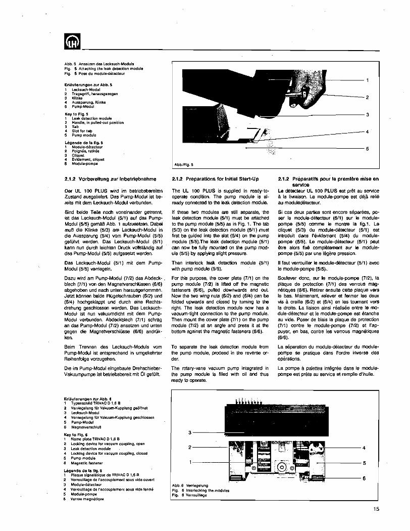
~-------------------------Abb. 5 Ansetzen des lecksuch-Moduls Fig. 5 Attaching Il'Ie leak defection module Fig. 5 Pose du module-chi'ecleUr
Erlauterungen zur Abb. 5 1 leckslIch·Modul 2 Tragegrllf, herausgezogen 3 Klinke 4 Aussparung, Klinke 5 Pump-Modld
Key 10 Fig_ 5 1 Leak detecl10n module 2 Handle, in puiled-oul position :3 TOib 4 Sial for lab 5 Pump module
Legende de Ie fig. 5 1 Module-detecteur 2 Poigruie, retiree 3 Clique! 4 Evldemenl, clique! 5 Module-pompa
2.1.2 Vorbereitung zur Inbetriebnahme
Der UL 100 PLUS wird im betriebsbereiten Zustand ausgeliefert. Das Pump-Modul ist bereits mit dam Lecksuch-Modul verbunden.
Sind beida Teile noch voneinander getrennt, ist das Lecksuch-Modul (5/1) auf das PumpModul (5/5) gemaB Abb. 1 aufzusetzen. Dabei mul3 die Klinke (5/3) am Lecksuch-Modul in die Aussparung (5/4) vom Pump-Modul (5/5) gefOhrt werden. Das Lecksuch-Modul (5/1) kann nun durch leichten Druck vollstandig auf das Pump-Modul (5/5) aufgesetzt werden.
Das Lecksuch-ModuJ (5/1) mit dem PumpModul (5/5) verriegeln.
Dazu wird am Pump-Modul (7/2) das Abdeck- . blech (7/1) von den Magnetvarschlussen (6/6) abgehoben und nach unten herausgenommen. Jetzt konnen beide Flugelschrauben (6/2) und (6/4) hochgekJappt und durch eine Rechtsdrehung geschlossen werden. Das LecksuchModul ist nun vakuumdichl mit dam PumpModul verbunden. Abdeckblech (7/1) schrag an das Pump-Modul (7/2) ansetzen und unten gegen die Magnelverschlosse (6/6) andrOkken.
Beim Trennen des Lecksuch-Moduls yom Pump-Modul ist entsprechend in umgekehrter Reihenfolge vorzugehen.
Die im Pump-Modul eingebaute DrehschieberVakuumpumpe ist betriebsbereit mit 01 geffillt
Erliuterungen zur Abb. 6 1 Typenschlld TRIVAC 0 1,6 a 2 Verriegelung IIIr Vakuum·Kupplung geoflnet 3 lecksuch-Modul 4 Verrieglliung fijI' Vakuum·Kupplung geschlossen 5 Pump-Modul 6 MagnetverschluB
Key to Fig. 6 1 Name plate TRIVAC 0 1 ,6 B 2 lockIng device lor vacuum CQupllng, open 3 leak detectIon module 4 Locking devlca lor vacuum cQupllng, closed 5 Pump module 6 Magnetic lastaner
Legende de la fig. 6 1 Plaque signalEitlqua de TRIVAC a 1,6 B 2 VerrtJuillage de I'accouplement sous vide Quvert 3 MQdule·detecleur 4 Verrouillage de l'accouplement SQUS vide lerma 5 Module·pompa 6 VerrOIl magnetique
-----2
~ ______________ ~3
~=====: Abb.lFig.5
2.1.2 Preparations for Initial Start·Up
The UL 100 PLUS is supplied in ready-tooperate condition. The pump module is already connected to the leak detection module.
If these two modules are still separate, 'the leak detection module (5/1) must be attached to the pump module (5/5) as in Fig. 1. The tab (5/3) on the leak detection module (5/1) must first be guided into the slot (5/4) on the pump module (5/5).The leak detection module (5/1) can now be fully mounted on the pump module (5/5) by applying slight pressure.
Then interlock leak detection module (5/1) with pump module (5/5).
For this purpose, the cover plate (7/1) on the pump module (7/2) is lifted off the magnetic fasteners (6/6), pulled downwards and out. Now the two wing nuts (6/2) and (6/4) pan be folded upwards and closed by turning to the right. The leak detection module now has a vacuum-tight connection to the pump module. Then mount the cover plate (711) on the pump module (7/2) at an angle and press it at the bottom against the magnetic fasteners (6/6).
To separate the leak detection module from the pump module, proceed in the reverse or· der.
The rotary-vane vacuum pump integrated in the pump module is filled with oil and thus ready to operate.
3----
2---~
Abb. 6 Verriegelung Fig. 6 InlerlQcklng the modules Fig. B verrouillage
2.1.2 Preparatifs pour la premiere mise en service
La detecteur UL 100 PLUS est pret au service a la livraison. La module-pompe est deja relie au moduledetecteur.
5i ces deux parties sont encore separees, poser Ie module-detecteur (5/1) sur Ie modulepompe (5/5) comme Ie montra la fig.1. Le cliquet (5/3) du module-detecteur (5/1) est introduit dans I'evidement (5/4) du modulepompe' (5/5). La modula-detecteur (5/1) peut etre alors fixe completement sur Ie mOdulepompa (5/5) par una legere pression.
II faut verrouiller Ie module-detecteur (5/1) avec Ie module-pompe (5/5) •.
Soulever donc, sur Ie module-pompe (7/2), la plaque de protection (7/1) des venous magnetiqljes (6/6). Retirer ensuite cette plaque vers Ie bas. Maintenant, relever et fermer les deux vis a orei!1e (6/2) et (6/4) an les touroant vers fa draite. La liaison ainsi realisee entre Ie module-detecleur et Ie module-pompe est etanche au vide. Poser de biais la plaque de protection (7/1) contre Ie module-pompa (7/2) at I'appuyer, en bas, contre Jes verrous magnetiques (6/6).
La separation du module-detecteur du modulepompa se pratique dans I'ordre inverse des operations.
La pompe a palettes integree dans Ie modulepompe est prete au service et remplie d'huile.
- .. :r----4
---,1------ 5
,E~----6
15
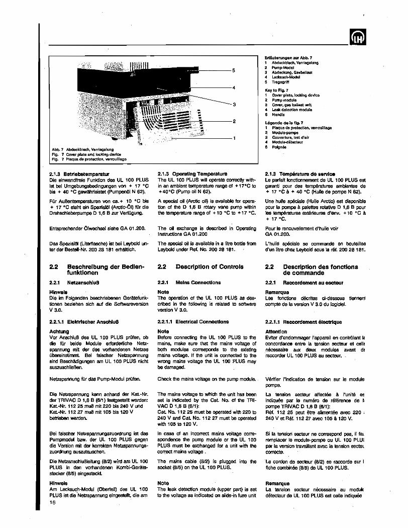
--------------------------~
Abb.7 Abdeekblech, Verrregelung FIg. 7 Cover plate and lockIng device FIg. 7 Plaque de protection, verroulUaga
2.1.3 Betrlebstemperatur Die einwandfreie Funktion des UL 100 PLUS ist bei Umgebungsbedingungen von + '7 °C bis + 40°C Qewahrleistet (PumpenOI N 62).
FOr AuBentemperaturen von ca + 10°C bis + '7 °C steht Bin SpeziaJOI (Arctic-Ol) fOr die Drehschieberpumpe 0 1,6 B zuy VerfOgung.
Entsprechender Olwechsel siehe GA 01.200.
Cas SpezialOI (Literflasche) ist bei Leybold un· ter der Bastell·Nr. 200 28 181 erhtdtlich.
2.2 Beschrelbung der Bedlen-funktlonen
2.2.1 NetzanschluB
Hlnwe18 Die im Foigenden beschriebenen Geratefunktionan beziehen sich auf die Softwareversion V 3.0.
2.2.1.1 Elektrlacher AnschluB
Achtung Var AnschluB des UL 100 PLUS prOfsn, ob die fOr beida Module eriorderliche Netzspannung mit der des vorhandenen Netzes Obereinstimmt. Bel 1a1scher Netzspannung sind BescMdigungen am Ul 100 PLUS nicht auszuschlieBen.
Netzspannung fOr das Pump-Modul prOfsn.
Die Netzspannung kenn anhand der Kat.-Nr. der TRIVAC 0 1,6 B (611) feslaestel~ werden: Kat-Nr. 112 25 muB mit 220 bis 240 V und Kat-Nr. 112 27 muB mit 105 bis 120 V betrieben werden.
Bei falscher Ne1zspannungszuordnung ist das Pumpmodul bzw. der UL 100 PLUS gage.n die Version mit der korrekten Netzspannungszuordnung auszutauschen.
Die NetzanschluBleitung (8/2) wird am UL 100 PLUS in den vorhandenen Kombi-Ger/ite_ker (8/5) eing'-kt.
Hinweis Am Lecksuch-Modul (Oberteil) des UL 100 PLUS ist die "Netzspannung eingestellt die am
16
3
-'~---2
2.1.3 Operating Temperature The Ul 100 PLUS will operate correctly within an ambient temperature range of + 17°0 to +40°0 (Pump oil N 62).
A special oil (Arctic oil) is available for operation of the D 1,6 B rotary vane pump within the temperature range of + 10°C to + 17 °0.
The oil exchange is described. in Operating Instructions GA 01.200
The special oil is available in a litre bottle from Leybold under Ref. No. 200 28181.
2.2 Description of Controls
2.2.1 Mains Connections
Note The operation of the UL 100 PLUS as des· cribed in the following is related to software version V 3.0.
2.2.1_1 Electrical Connections
Note Before connecting the Ul 100 PLUS to the mains, make sure that the mains voltage of both modules corresponds to the existing mllins voltage. If the unit is connected to the wrong mains voltage the UL 100 PLUS may be damaged.
Check the mains voltage on the pump module.
The mains voltage to which the unit has been set is indicated by the Cat No. of the TRIVAC 0 1,6 B (611): Cat No. 1 1.2 25 must be operated with 220 to 240 V and Cat No.1 12 27 must be operated with 105 to 120 V.
In case of an incorrect mains voltage correspondence the pump module or the UL 100 PLUS must be exchanged for 8 unit with the correct mains voltage .
The mains cable (8/2) is plugged into the socket (8/5) on the UL 100 PLUS.
Note The leak detection module (upper part) is set to the voltage as indicated on slide-in fuse unit
Erlluterungen zur Abb. 7 1 Abdackblech, Varrlagalung 2 Pump-Modul 3 Abdackung, Gasballasl 4 Lacksuch·Modul 5 Tragagrltt
Key to FIg. 7 1 Covar plaia, locking davlce 2 Pump moclula 3 Cover, gas ballast unit 4 Leak datactlon moclula 5 Handla
LO;ende de la fig. 7 1 Plaqua da protection, verrouillage 2 Module-pompa 3 Couvartura, lest d'alr 4 Modula-dataClauT 5 Poignae
2.1.3 Temperature de service Le parfait fonctionnement de UL 100 PLUS est garanti pour des temperatures ambiantes de + 17 ·C a + 40 ·C(Huile de pompe N 62).
Une huile speciale (Huile Arctic) est disponible pour la pompa a palettes rotative D 1,6 B pour les temperatures extBrieures d'env. + 10°C a + 17 °C.
Pour Ie renouveUement d'huile voir (lA 01.200.
L'huile speciale se commande en bouteilles d'un litre chez leybold sous la ref. 200 28181'.
2.2 Description des fonctlons de commande
2.2.1 Raccordement au &ecteur
Remarque Les fonctions decrites ci-dessous tiennem compte de la version V 3.0 du logiciet.
2.2.1.1 Raccordement electrlque
Attention Eviter d'endommager I'apparell en controlant I~
concordance entre la tension secteur at celiE necessaire aux deux modules avant dE raccorder UL 100 PLUS au secteur.
Verifier I'indication de tension sur Ie module pompeo
La tension secteur affectee a I'unite eE indiquee par Ie numero de reference de ~ pompe TRIVAC 0 1,6 B (611): RM. 112 25 paut ~ alimentee avec 220 ; 240 V et Ret. 11227 avec 105 a 120 V.
Si la tension secteur ne correspond pas, iI fal remplacer Ie module-pompe au UL 100 PLUl par 18 version travaillant avec la tension sectel correcte.
La cordon de secteur (812) se raccorde sur I fiche combinee (8/5) de UL 100 PLUS.
Remarque La tension secteur n9cessaire au modulE detecteur de UL 100 PLUS est celie indiques
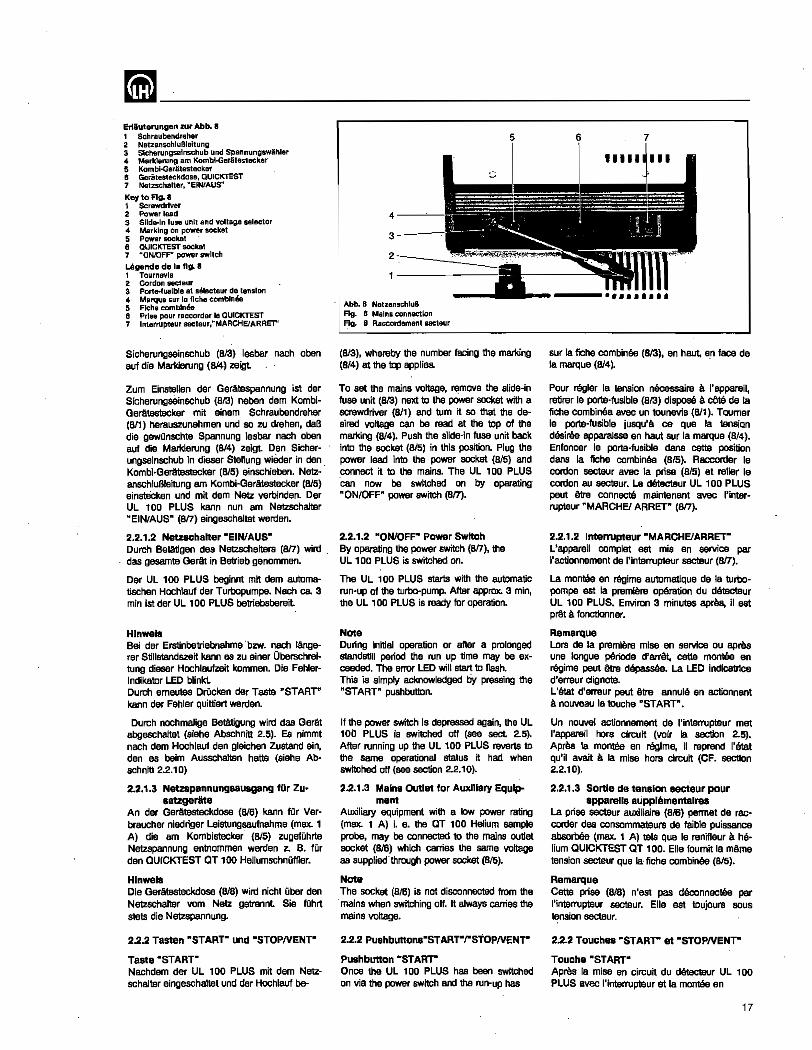
mm ________________________ __ Erlluterungen zur Abb. I 1 Schraubendreher 2 NetzanschluBleltung 3 Sicherungsainschub und Spannungswihler 4 Marklerung am KombloGer.litestecker 5 Kombl-Geriitestecker 8 GeraleS1eckdose, QUICKl'EST 7 Nel~chalter. "EINlAUS·
Key to FIg. a 1 Screwdriver 2 Power lead 3 Slide-In fuse unit and voltage selector '" Marking on power socket 5 Powar socket 6 QUICKTEST socket 7 ~ONlOFF" power switch
U!gende de 18 fig. 8 , Tournevls 2 Cordon &eCtaur 3 Porte-fusible at selecteur de tension '" Marque sur Ie fiche combineD 5 Fiche comb!nea 6 Prise pour raccordsr Ie QUICKTEST 7 Interrupteur secteuf,"MARCHEIARRET"
Sicherungseinschub (8/3) lesbar nach aben auf die Markierung (8/4) zeigt
Zurn Einstellen dar GerAtespannung ist dar Sicherungseinschub (al3) neben dam KombiGeJ'Atestecker mit einem Schraubendreher (8/1) herauszunahmen und so zu drehen, daB die gewQnschte Spannung lesbar nach oben auf die Markierung (814) zeigt Den Sicherungseinschub in dieser Stellung wieder in den" Kombi-Geratestecker (815) einschieben. NetzanschluBleitung am Kombi-Ger&testecker (815) einst8cken und mit dem Netz verbinden. Der UL 100 PLUS kann nun am Netzscha/ter "EIN/AUS" (817) eingeschaltet werden.
2.2.1.2 NetzschaHer "EIN/AUS" Durch Betatigen des Netzschalters (817) wird " das gesarnte GerM in Betrieb genom men.
Der UL 100 PLUS beglnnt mit dem automatischen Hochlauf der Turbopumpe. Nach ca. 3 min ist der UL 100 PLUS betriebsbereit
Hlnwel8 Bei der Erstinbetriebnahme "bzw. nach IAngerer Stillstandszeit kann as zu einer Oberschreitung dieser Hochlaufzeit kommen. Die FehlerIndikator LED blinkt. Durch emeutes DrOcken der Taste "START" kann der Fah[er quittiert werdan.
Durch nochmalige Betatigung wird das Ger&t abgeschaltet (siaha Abschnitt 2.5). Es nimmt nach dem Hochlauf den gleichen Zustanc:l ain, dan as bairn Ausschalten hatte (siehe Abschnitt 2.2.10)
2.2.1.3 Netzapannungsausgang fiir Zu .. satzgeriite
An der GerAtesteckdose (816) kann ffir Verbraucher niedriger Leistungsaufnahme (max. 1 A) die am Kombistecker (B/5) zugefuhrte Netzspannung entnommen werden z. B. fur den aUICKTEST aT 100 Heliumschnuffler.
Hlnwel8 Die Geratesteckdose (816) wird nicht Obar den Netzschaltar vom Netz getrennl Sie fOhrt stets die Netzspannung.
2.2.2 Tasten "START" und "STOPNENT"
Taste "START" Nachdem der UL 100 PLUS mit dem Netzschalter eingeschaltet und der Hochlauf be-
3--~
2 __ ---':::.:::::-"
Abb. 8 NetzanschluB Fig. 8 Mains connection Fig. 8 Raccordament secteur
5
(813), whereby the number facing the marking (814) at the top applies.
To set the mains voltage, I'E!mave the slide-in fuse unit (813) next to the power socket with a screwdriver (8/1) and tum it so that the desired voltage can be read. at the top of the marking (814). Push the slide-in fuse unit back into the socket (SIS) in this position. Plug the power lead into the power socket (815) and connect ij to the mains. The UL 100 PLUS can now be switched on by operating "ONIOFF" power switch (817).
2.2.1.2 "ON/OFF" Power Switch By operating the power switch (817), the UL 100 PLUS is switched on.
The UL 100 PLUS starts with the automatic run-up of the turbo-pump. After apprax. 3 min, the UL 100 PLUS is ready for operation.
Note During initial operation or after a prolonged standsHl[ period the run up time may be exceeded, The error LED will start to flash. This is simply acknowledged by pressing the "START" pushbutton.
[f the power switch is depressed again, the UL 100 PLUS is switched off (see sect 2.5). After running up the Ul100 PLUS reverts to the same operational status it had when switched off (see section 2.2.10).
2.2.1.3 Mains Outlet for AuxJllary Equip.. ment
Auxiliary equipment with a low power rating (max. 1 A) i. e. the aT 100 Helium sample probe, may be connected to the mains outlet socket (816) which carries the same voltage as supplied through power socket (815).
Note The socket (816) is not disconnected from the mains when switching off. It always carries the mains voltage.
2.2.2 PushbUllons"START"rSTOPNENT"
Pushbutton "START-Once the UL 100 PLUS has been switched on via the power switch and the run-up has
6
11111 III
sur Ia fiche combinee (813), en haut, en face de 10 marque (8/4~ .
Pour regler la tension necessaire s I'appareil, retirer Ie porte'fusible (813) dispose a cOlO de Ie fiche combinee avec un tounevis (8I1). Toumer Ie porte-fusible jusqu's ce que Ia tension desires apparalsse en haut sur la marque "(8/4). Enfoncer Ie porte-fusible dans cette position dans la fiche combinee (815). Raccorcler Ie cordon secteur avec la prise (8/5) et relier Ie cordon au secteur. Le detecteur UL 100 PLUS peut eve connecte maintenant avec I'interrupteur "MARCHEf ARRET" (817).
2.2.1.2 [nterrupteur -MARCHEIARRETL'appareil complet est mis en service par I'actionnement de I~interrupteur secteur (8n).
La montee en regime automatique de la turbopompe est la premiere operation du detecteur UL 100 PLUS. Environ 3 minutes apres, iI est prAt a fonctionner.
Remarque Lors de la premiere mise en service ou apree une langue periode d'arret. cette montee en regime peut _ depass6e. La LED indicatrlce d'erreur c1ignote. L'lItat d'erreur peut titre annule en actiannant a nouveau [8 touche "START".
Un nouvel actionnement de I'interrupteur met I'appareil hers circuit (voir fa section 2.5). Aprea la montee en regime, it reprend l'lItat qu'il avan a [a mise hors circuit (OF. section 2.2.10).
2.2.1.3 Sonle de tension 8ecteur pour apparell8 lupplementalres
La prise secteur euxiliaire (816) pennet de raecorder des consommateurs de faible puissance abaorbOe (max. 1 A) 181. que Ie renifleur a he· lium QUICKTEST QT 100. Elle foumij 10 mame tension secteur que la" fiche combinee (Sl5).
Remarque Cette prise (816) n'est pas deconnectee par I'interrupteur secteur. Elle est toujours sous t~nsion secteur.
2.2.2 Touch .. "START"' at "STOPNENT"
Touche -START"' Apres la mise en circuit du detecteur UL 100 PLUS avec l'interrupteur et 18 montee en
17
___________________________ mm endet 1st, erfolgt die waiters Bedienung mit der Taste "START" (4124) und der Taste "STOP I VENT" (4/2).
Durch kurzes OrOcken dBr Taste "START" wird ein angeschlossener Pnifling evakuiert, gleichzeitig leuchtet die Status-LED (4/1) grOn.
Der fallende. EinlaBdruck PE wird auf der Kambi-Anzeige (413) angezeiglf bis der EinlaBdruck von Pe < 0,2 mbar 1st Bei diesem EintaBdruck wire! automatisch die Kombi-Anzeige (4/3) so umgeschaJtet. daB anstelle des EinlaBdrucks die Leckrate angezeigt wird.
WAhrend 1m MeBbetrieb die Leckrate angezelgt wird. kann mit jedem weiteren Druck auf die Taste "START" die angezeigte leckrate auf einen evtI. angeschlossenen Drucker ausgegeben werden (PRINT ONLY -Betrieb siehe Schnittstellenbeschreibung S8 10.207).
Taste· STOP I VENT" Ausgehend yom MeBbebieb des UL 100 PLUS wird durch einmaliges kurzes OrOckan der Taste "STOPNENT" (412) des Evakuie· ran des PrOflings unterbrochen. Der UL 100 PLUS geht in den Stand-By-Zustand.
Oem Bediener wir:d dieser Zustand wie folgt angezeigt - Die angezeigte Leckrate wird ausgeblendet.
die lED's (413) sind aile aus. - Die rot-grune Status-lED (4/1) erlischl - Die Exponenten sind weiterhin slchtbar. - 1m Service1eld wird aut der Status~ 1 Fehler-
anzeige (26/1) "STBY" angezeigt. - Die LED-Zero (4/21) leuchtel
Nach dem Drucken der Taste "STOPNENT" (412) ertolgt ein Selbstabglelch des Ul 100 PLUS. Hierbei wird d~r gerAteinteme Heliumuntergrund und die elektrische Nullpunktverschiebung bestimmt
Durch langeres OrOcken (mindestens 2 s) der Taste "STOPNENT" (4/2) wird die Funktion VENT (Fluten) arreicht Das Flutventil V3 wird geOffnet Der PrOfIing wird hOrbar geflutel Dieser BetriebszuBtand wird durch rotes Auf[euchten dar Status-LED (4/1) gemaldel Die LEOs der Kombi-Anzeige (413) sind aile aus.
Das Flutventil V3 kann wieder geschlossen werden durch - nochmaliges ONckan der Taste "STOPI
VENT". Dar UL 100 PLUS geht in den Standby-Zustand oder
- Taste "START" (4/24) drucken. Dar UL 100 PLUS geht in den MeBbetrieb zurUck.
2.2.3 Wertelngab&o Tasten Nach Bet!tigen einer Multifunktionstaste kOnnen Qber die Werteingabe-Tasten (4/19) und (4/6) Parameter ins Gerat eingegeben werden. Zum Beispiel kann nach vorherigam Betatigen der Multifunldions-Taste "Akustisches Signal" (4/16) die Lautstarke des akustischen Signals eingestellt werden.
Hlnwels Mit den Werteingabe-Tasten (4/19) und (4/6) kann nur die Funidion beeinfluBt werden, die jeweils auf einer der Multifunktions-Tasten vorgewflhlt uoo Qber eine LED angezeigt wird.
18
been completed, further operation is carried out with the "START" (4/24) and "STOP I VENT" (412) pushbuttons.
By briefly depressing the "START" pushbut· ton (4/24), the test object is evacuated, during which time the status LED (4/1) is green.
The dropping intake pressure PE is shown on the combined indicator (413) until pressure PE is < 0.2 mbar. At this value of the intake pressure, the combined indicator (413) automatically changes over to leak rate indication instead of inlet pressure indication.
During indication of a leak rate in the measuring mode. each depressing of the " START" pushbutton will output the displayed leak rate on a printer if connected (PRINT ONLY mode see instructions for the interface SB 10.207).
Pushbutton' STOP I VENT" When the UL 100 PLUS is in the measurement mode, evacuation of the test object can be interrupted by briefly pressing the "STOP I VENT" (412) pushbutton once. The Ul 100 PLUS then _ itseij to _dby.
This condition is indicated to the operator as follows: - The displayed leak rate disappears, LED's
(413) are ail off. - The redlgreen status lED (4/1) is off .. - The exponents are still visible. • The status/error diplay (26/1) on the service
panel indicates "STBY". - The zero LED (4121) is on
After pressing "STOPNENT" (4/2) the seHalignment process of the UL 100 PLUS is started. Both internal helium background and electrical zero shift ar~ determined.
By pressing the pushbutton "STOPNENT" (412) for a longer period of time (for at least 2 s) the venting process can be started. Venting valve V3 is opened. The test object is audibly vented. This operating condition is indicated by the status LED (4/1). The lEDs on the combination display (4/3) are all ~ff.
Venting valve V3 can be closed again by
- again operating the "STOPNENT" pushbutton. The UL 100 PLUS returns to standby or
- operating the "START" (4/24) pushbutton. The UL 100 PLUS returns to the measurement mode.
2.2.3 Parameter Pushbuttona After operating a program pushbutton, parameters can be entered with the, parameter pushbuttons (4/19) and (416). For example, after previously operating the acoustic signal multi-function pushbutton (4/16), the volume of the acoustic signal can be adjusted.
Note With the parameter pushbuttons (4/19) and (4/6) one can only influence a function previously selected with a multi-function pushbutton and indicated by the relevant LED.
regime de la pompe ia commande est poursuivie avec la touche "START" (4124) et la touche "STOPNENT" (412).
La piBce raccordee est evacuee en tapant brievement la touche "START" (4124), simultanament la DEL d'etat verte (4/1) sallume.
La pression d'admission decroissante PE est in· diquee sur I'affichage combine (413) jusqu'a la valeur PE < 0,2 mbar. Quand cette valeur est attainte, I'affichage combine (413) est commute automatiquement de telle sorte que ce soit Ie taux de fuite et non ia pression d'admission qui soit affich8.,
Pendant I'affichage de taux de fuite en mode mesure, chaque pression sur la touche "START" provoque une sortie du taux actual sur "imprimante eventuellement raccordee (mode PRINT ONLY voir description d'interface SB 10.207).
Touche ·STOP 1 VENT' Lorsqua UL 100 PLUS est en mode de me· sure, on paut interrompre I'evacuation de la piece raccordee en actionnant, une saule foi~ et briOv.men~ Ie touche "STOPI VENT" (4/2). Ul 100 PLUS passe aiors en mode Stand·By.
Cet etat est indique a I'operateur de la fSCOr suivante: - Le taux de fuits indique disparait, les DEL
(413) sont toutes etaintes. - La DEL rouge·verts (4/1) s'eteinl - Las exposants restsnt vis/bles. - L'affichage d'etatld'erreur (26/1) du panneBl
de service indique "STBY". - la DEL du zero (4/21) s'ailume
L'equlHbrage 8utamatique de UL 100 PLUS I lieu apree I'actionnement de la touchl "STOPNENT" (412). le rond helium de I'op pareil et 18 derive electrique du zero sont alar. determines.
On obtient la fonction VENT (remise a I'atrnos phere) en actionnant plus longtemps (au moin: 2 s) 18 touche "STOPNENT" (412). Le robine de fuite V3 est ouvert. On entend distinctemer la remise a ratmosphere de 18 piece raccordee Cat Stat de service est signale par I'allumagl de Ie DEL d'etat (4/1). Las DEL de I'affichag combine (413) sont toutes eteintes.
Le robinet de fuits V3 peut Atre referme en
- actionnant une nouvelle fois la touch "STOPNENT". Ul 100 PLUS passe e mode Stand-By au en
- actionnant 18 touche "START" (4/24). U 100 PLUS revient en mode mesure.
2.2.3 Touches d'entree de valeurs Ce type de .touche (4/19) et (4/6) perme apres I'actionnement d'une touche programme d'introduire des parametres. II est par exempl possible en appuyant avant sur la touc~ multifonction "signal acoustique" (4/16), c realer l'intensitB du signal sonore.
Remarque Les touches d'entree des Valeurs (4/19) (4/6) ne peuvsnt influencer que la fonction ( la touche precedemment choisie et indlquE par une DEL.
~----------------------~-Die Werteingabe wird durch DrOcken dar Taste (4/19) vergrOBert und durch Dnlcken dar Taste (416) verkleinert. SiB wird erst mit DrQcken dar Taste Eingabe-Ende "ENTER" (4/l3) abgeschlossen und damit wirksam.
2.2.4 MeBberelchswahl-Taste "Automatlk"/"Triggerloglk"
Durch Beta.tigen dar Taste MeBbereichswahl "Automatik" (4118) wl!h~ der UL '00 PLUS automatisch den richtigen Me13bereich und zeigt diesen auf dar Kombi-Anzeige (413) an. Urn den jeweiligen Prof· bzw. MeBvorgang ohne VerzOgerungen durchfOhren zu kOnnen, empfiehlt BS sieh, den UL 100 PLUS auf Automatikbetrieb einzustBUen.
Als Sonderfunktion wird clie Taste bel dar Programmierung dar Trigger zur Umschaltung zwischen Normal- und Invers-Betrieb verwendet (slaha Abschnitt 2.2.8.2).
2.2.5 MeBberelchswahl·Ta81e "Hand"
Durch das Betatigen dar MeBbereichswahlTaste "Hand" (4/8) wird das automat AuswAhlen . des richtigen MeBbereiches abgeschahet Der MeBbereich muB Dber die Werteingabe-Taste (4/19) u. (416) eingestelJt werden und kann an den Exponenten (4/4) bzw. (4/5) abgelasen werclen. Durch eine in der MeBbereichswahl-Taste "Hand" vorhandene lED (4n) wirel diese Funktion angezeigt.
Bei Verwendung der Option Teilstrompumpsatz kann mit Hitfe der Taste "HAND" und der Werteingabetaste (416) manueU in den empfindlichsten MeBbereich (ULTRA) geschaltet werden. (Sieha Abschn~ 2.4.7.1).
2.2.& Nullpunkt-Taste -Auto-Zero"
1m MeBbetrieb wircl eine stOrende konstante Untergrundanzeige durch einmaliges Betatigen dar Nullpunkt-Taste (4/14) untercirOckt.
Ab Softwareversion V3.4 wirkt die Nullpunkttaste zusatzlich auf die TriggerausgAnge (Abschnitt 2.2.8) und auf die Analog· Spannungs·Ausgange (Abschnitt 2.2.13.6).
Die leckraten-Anzeige wird automatisch auf Null gesetzt und die Null·lndikator lED (4/21) blinkt.
Befindet sich der angezeigte Helium-Untergrund in der unteren Dekacle, so wircl der MeBbereich eine Dekacle empfindlicher gewAhIt Ein Umschalten in empfindHchere MeBbereiche ist nun nicht mehr mOgHch. Ein Absinken des Untergrundes wird durch eine gleitende Untergrundbestimmung korrigiert.
Durch nochmaliges Beta.tigen der NullpunktTaste (4/14) wird die Funktion aufgehoben, ein eventueller Untergrund wird wieder als leckrate angezeigt
2.2.7 MuHlfunktlons-Taste "Akustlsches SignallO
Hlnwels Die Betatigung dieser Taste und ihre Funktion kOnnen in allen Betriebsarten eOOlgen.
Mit der Multifunktions-Taste .. Akustischas Signal" (4/16) kann die lautstarke bzw. der Ein·
The value of the parameter is increased by pressing pushbut10n (4119) and decreased by pressing pushbutton (416). The entry does not take effect until the "ENTER" pushbutton (4113) has been depressed.
2.2.4 Range Selector Pushbutton • Automatlc"rTrigger logic"
By depressing the automatic measuring range selector (4118), the UL '00 PLUS automatically chooses the right measuring range and indicates it on the combined indicator (413). To perlann testing and measurement without delays,it is advisable to set the Ul 100 PLUS to automatic operation.
As a special function this pushbutton is used to switch between normal and inverse mode during the programming process' of the trig~ gers (see section 2.2.8.2).
2.2.5 Measuring Range Selector "'Man-ua'"
If the manual measuring range selector (4/8) is depressed, automatic selection of the right measuring range is switched off. The measuring range must now be entered with the parameter pushbut1on. (41'9) and (4/6) and can be read off directly at the exponents (4/4) and (4/5). This function is indicated by the LED (4n) on the measuring range selector.
When the optional partial flow pump set is used, the "MANUAL- pushbutton and the paM rameter pushbutton (4/6) may be used to manuafly switch over to the most sensitive (ULTRA) range (see also Section 2.4.7.1).
2.2.6 Pushbutton "'Auto Zero·
In the measurement mode, an unwanted constant background reading is supppressed by pressing the autozero pushbutton (4114) once.
As of software release V 3.4 the Zero pushbutton additionally affects the trigger outputs (Section 2.2.8) and the analogue voltage outpUlS (SBC1ion 2.2.13.6).
The leak rate indication is automatically set to zero and the zero indicating lED (4/21) flashes.
If the displayed helium background is in the lower part of a decade the next, more sensitive range is selected. Further switch oVer to an even more sensitive range is then no longer possible. A possible further reduction of the background will now be automatically accounted for by the adaptive background determination process.
If the auto zero pushbutton (4/14) is depressed again, the function is cancelled and any background is again displayed as leak rate.
2.2.7 Multl~Functlon Pushbutton "Acoustic SignaI'"
Note Operation of this pushbutton is possible in all operating modes.
With the aCoustic signal multi""function pushbutton (4116) one can adjust the loudness or
La valeur est augmentee en actionnant la touche (4/19) at diminuee par la touche (416). l'introduction n'est tenninee et donc activ8e qu'en actionnant la touche fin d'entree "EN~ TER" (4113).
2.2.4 Touche de selection "automat. .. , "trigger log. n des gammas de mBS.
l'actionnement de cette touche (4/18) declenche dans Ie' detecteur UL 100 PLUS Ie choix automatique de la gamma de mesure correcte at son indication sur !'affichage combine (4/3). Ce service automatique du detecteur UL 100 PLUS est conseiUe pour ne pas pereira de temps avec les differentes operations de contr"Ole au de mesure.
Pour la programmation des triggers ceHe touche a la fonction speciale de commuter entre mode nonnal at mode inverse (CF. section 2.2.8.2).
2.2.5 Touche de selection "manuelle" des gammes de mesure
l'actionnement de cette touche "manuelle" (4/8) arrete la selection automatique de la gam· me de mesure eorrecte. Celle-cl doit etre introduite au moyen d'une touche d'entree (4/19) ou (416). Elle paut lUre lue immediatement avec leS exposants (4/4) ou (4/5). la fonction est indiquee par une DEL (4n) sur is touche "manuelle" (selection manueile).
Avec I'option groupe de pompage Ii flux partiel, on utilise la touche "manuelle" at la touche d'introduction de valeurs (4/6) pour commuter· manuellement sur la gamme de mesure la plus sensible (ULTRA). (Cf. section 2.4.7.1).
2.2.& Touche de remise a zero "auto-zero"
En mode mesure I'affichage d'une valeur para~ site constanta paut ette supprime en actionnant la touche de remise a zero (4114).
A partir de la version V 3.4 du logiciel, !'action de la touche point zero s'etand egalement aux sorties trigger (section 2.2.8) et aux sorties de tension analogique (section 2.2.13.6).
l'afflchage de taux de fuite revient automatiquement a zero et la DEL du zero (4121) clignote.
La gamme de mesure sera choisie d'une decade plus sensible si Ie fond Mlium afficM se trouve dans la decade inffirieure. II n'est a10rs plus possible de commuter sur des gammas plus sensibles. La reduction du fond est corrigse par une determination flottante du fond.
En appuyant une nouvelle fois 'sur la touche de remise a zero (4/14), cette fonction est annulee at un eventuel fond parasite est affiche en tant que taux de fuite.
2.2.7 Touche muHtfonctlon "signal acou· stlque·
Remarque Cetta touche de fonotion est operante pour taus las modes de service.
la touche multifonction "Signal acoustique" (4/16) pennet de regler l'intensit8 sonore ou Ie
19
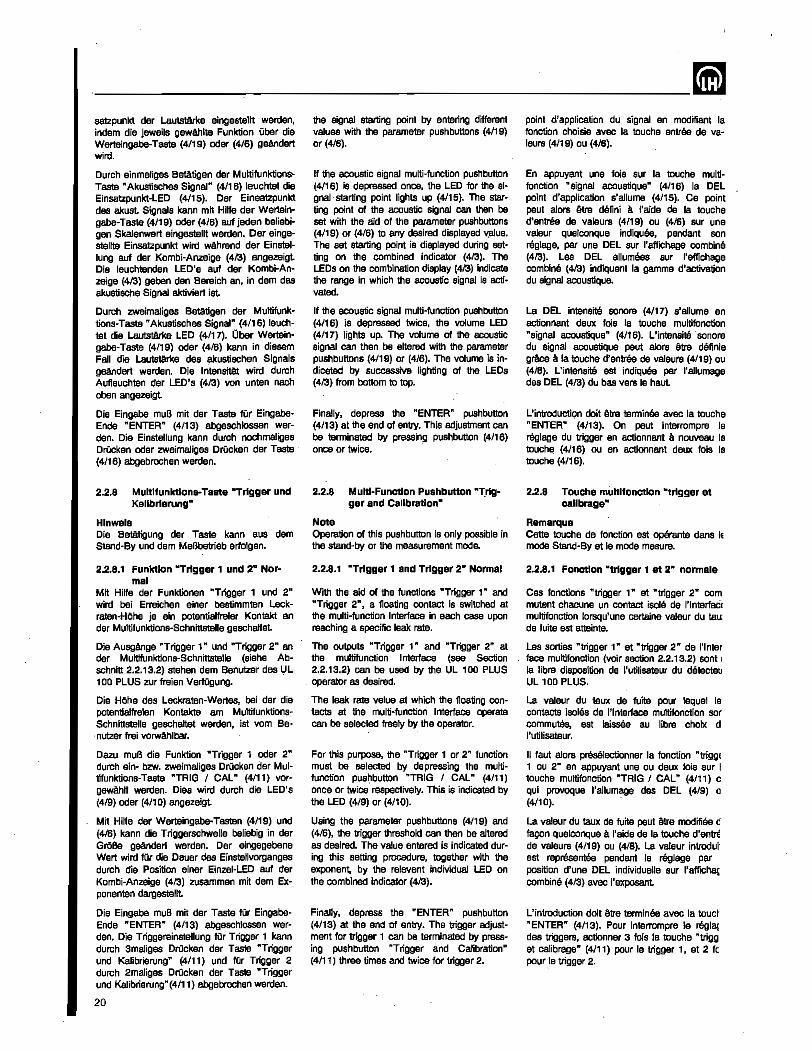
____ -'--________ il satzpunkt der LautstArke eingesteltt werden, indem die jewells gewAhlte Funktion uber die Werteingabe-Taste (4/19) oder (4/6) geAndert wird.
Durch einmaliges Beta.tigen der MuttifunktioosTaste "Akustisches Signal" (4/16) leuchta! die Einsatzpunkt-LED (4115). Der EinsBtzpunkt des akust Signals kann mit Hilfa der Wertsingabs-Taste (4119) oder (4/6) auf jeden beliebigen Skalenwert eingestellt werden. Der eingesteltte Einsatzpunkt wird wAh rend der Einstallung auf der Kombi-Anzeige (4/3) angezeigl Die leuohtenden LED's auf der Kombi-Anzelge (413) geben den Bereich an, in dam das akustische Signal aktiviert ist
Durch zweimaJiges Betatigen dar Multifunktions-Taste "Akustisches Signal" (4/16) leuchtel die Lautstarke LED (4/17). Ober Werleing8be-Taste (4/19) oder (4/6) kenn in diesem Fall die Lautstarke des akustischen Signals geAndert werden. Die Intensttlit wird durch Aufleuchten der LED's (413) von unten nach aben angezeigt.
Die Eingabe muB mit der Taste fOr EingabeEnde "ENTER" (4/13) ebgeschlossen werden. Die Einstel1ung kann durch nochmaliges DrUcken oder zweimaliges Drucken der Taste (4/16) abgebrochen werden.
2.2.8 Multlfunktlons-Taste "Trigger und Kallbrlerung"
Hlnwels Die BetMigung der Taste kenn aus dem Stand-By und dem MeBbetrieb erfolgan.
2.2.8_1 Funktlon "Trigger 1 und 2" Nor .. mal
Mit Hilte dar Funktionen "Trigger 1 und 2" wird bei Erreichen einer bestimmten Leekraten-HOhe je ein potentialfreier Kontakt an der Multilunktions-Schnittstelle geschahat
Die Ausgo1nge "Trigger 1" und "Trigger 2" an der Multifunktions-Schnittstelle (siehe Abschnitt 2.2.13.2) stehen dem Benutzar des UL 100 PLUS zur lreien VerfOgung.
Die HOhe des Leckraten-Wert_BS, bei der die potentialfreien Kontakte am MultifunktionsSchnittstelle geschaltet werden, ist vom Benwer lrei vorwflhlbar.
Dazu muB die Funktion "Trigger 1 oder 2" durch ein- bzw. zweimaliges Drucken der Multifunktions-Taste "TRIG I CAL" (4/11) vorgewAhIt werden. Dies wird durch die LED's (4/9) oder (4/10) angezeigt
Mit Hilfe der WerteingalJ&.Tasten (4/19) und (4/S) kann die Triggerschwelle beliebig in der GroBe geandert werden. Der eingegebene Wert wird fOr die Dauer des Einstellvorganges durch die Position einer Einzel-LED auf der Kombi-Anzeige (413) zusammen mit dem Exponenten dargestellt
Die Eingabe muB mit der Taste fOr EingabeEnde "ENTER" (4/13) abgeschlossen werden. Die Triggereinstellung fOr Trigger 1 kann durch 3maliges DrOcken der Taste "Trigger und Kalibrierung" (4/11) und fUr Trigger 2 durch 2maliges Drucken der Taste "Trigger und Kalibrierung"(4/11) abgebrochen werden.
20
the signal starting point by entering different values with the parameter push buttons (4/19) or (4/6).
If the acoustic signal multi-function pushbutton (4116) is depressed once, the LED for the signalstarting poinl lights up (4/15). The starting point of the acoustic signal can then be set with the aid of the parameter pushbuttons (4/19) or (4/6) to any desired displayed ~ue. The set starting point is displayed during setting on the combined indicator (413). The LEOs on the combination display (413) indicate the range in which the acoustic signal is activated.
If the acoustic signal multi-function pushbutton (4116) is depressed twice, the volume LED (4/17) lights up. The volume of the acoustic signal can then be ahared with the parameter pushbuttons (4/19) or (4/6). The volume is indicated by successive lighting of the LEOs (4/3) ~om bottom to top.
Finally, depress the "ENTER" pushbutton (4/13) at the end of entry. This adjustment can be terminated by pressing pushbutton (4/16) once or twice. .
2.2.8 Multi-Function Pushbutton "rrlgger and Calibration·
Noto Operation of this pushbutton is only possible in the stand·by or the measurement mode.
2.2.8.1 '"Trigger 1 and Trigger 210 Normal
With the aid of the functions "Trigger 1" and "Trigger 2", a floating contact is switched at the multi-function Interface in each case upon reaching a specific leak rate.
The outputs "Trigger 1" and "Trigger 2" at the multifunction Interface (see Section 2.2.13.2) can be used by the UL 100 PLUS
. operator as desired.
The leak rate value at which the floating contacts at the multi~function Interface operate can be selected freely by the operator.
For this purpose, the "Trigger 1 or 2" function must be selected by depressing the multifunction pus~button "TRIG I CAL" (4111) once or twice respectively. This is indicated by the LED (4/9) or (4/10).
Using the parameter push buttons (4/19) and (4/6), the trigger threshold can then be altered as desired. The value entered is indicated during this setting procedure, together with the exponent, by the relevent individual LED on the combined indicator (413).
Finally, depress the "ENTER" pushbutton (4/13) at the end of entry. The trigger adjustment lor trigger 1 can be terminated by pressing pushbutton "Trigger and Calibration" (4/11) three times and twice for trigger 2.
point d'application du signal en modifiant la fonction choisie avec la touche entree de valeurs (4/19) ou (416).
En appuyant une 10is sur la touche multifonction "signal acoustique" (4116) la DEL point d'application s'a1lume (4115). Ce point paut a10rs etre dMini a I'aide de la touche d'entree de valeurs (4/19) ou, (416) sur une valeur quelconque indiquee, pendant son reglage, par une DEL sur I'affichage combine (413). Les DEL allumees sur I'affichage combine (413) indiquent la gamme d'activation du signal acoustique.
La DEL intensitlt sonore (4/17) s'allume en aqtionnant deux fois la touche multifonction "signal acoustique" (4116). L'intansitil'sonore du signal acoustique peut alors etre delinis grftce Ii la touche d'entree de valeurs (4/19) au (416). L'intensitB est indiquee par I'allumage des DEL (413) du bas vers Ie haul
L'introductiQn doit Atre termlnee avec la touche "ENTER" (4/13). On peut interrompre Ie reglage du trigger en actionnant Ii nouveau la touchE! (4116) ou en actionnant deux lois la touche (4116).
2.2.8 Touche muhlfonctlon "trigger et callbrage"
Remarque Cette to!Jche de fonotion est operante dans IE mode Stand-By at Ie mode mesura.
2.2.8.1 Fondlon "t,rlgger 1 et 2" normale
Cas fonctions "trigger 1" at "trigger 2" com mutent chacune un contact isola de l'lnterfacil multifonction lorsqu'une certains valeur du tau: de fuits est attainte.
Las sorties "trigger 1" at "trigger 2" de l'lnter face multifonction (voir section 2.2.13.2) sont l
la libra disposition de I'utilisateur du dBtecteu UL 100 PLUS.
La valeur du taux de fuita pour lequel Ie contacts isalas de l'lnteriace multifonction sor commutes. est laissee au -libre chobe d I'utilisateur.
II laut slors preselectionner la fonction "triggE 1 au 2" en appuyant una au deux lois sur I touche multifonction "TRIG I CAL" (4/11) c qui provoque I'allumage des DEL (4/9) 0 (4/10).
La valeur du taux de fuite peul etre modifiee c' facen quelconqus Ii I'aide de la touche d'entnl de valeurs (4/19) ou (4/6). La valeur introdur est representee pendant Ie reglage par position d'une DEL individuelle sur l'affichB!; combine (4/3) avec I'exposant
L'introduction doit we terminee avec la touct "ENTER" (4/13). Pour interrompre Ie regiS{ des triggers, actionner 3 fois la touche "trigg et calibrage" (4111) pour Ie trigger 1, at 2 fc pour .Ie trigger 2.
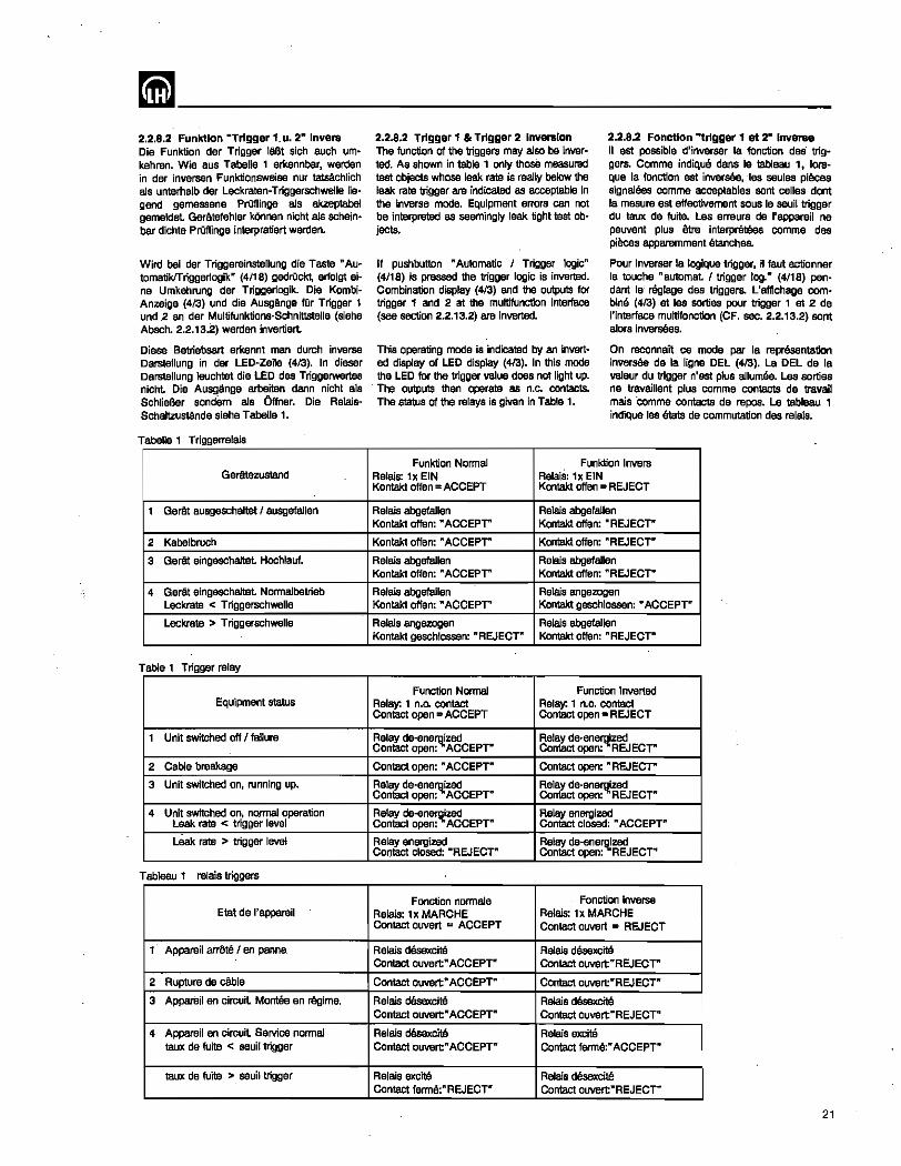
mm ________________________ __ 2.2.B.2 Funktlon -Trigger 1.u. 2- Invera Die Funktion der Trigger laBt 51ah auch urnkehren. Wie BUS Tabella' erkennbar. werden in der inversen Funktionsweise nur tatsAchlich a1s unterhalb der Leckraten-Triggerschwelle liegend gemessene PrOflinge a1s akzeptabel gemeldet GerAte1ehler kOnnen nicht a1s scheinbar dichte Pniflinge interpretiert werden.
Wird bei der Triggereinstellung die Taste "AutomatikITriggerlogik" (4118) gedrOckt, 8rfol91 aine Umkehrung der Triggerlogik. Die KombiAnzeige (413) und die Ausgfmge fOr Trigger 1 und ,2 an dar Multifunktions-Schnittstelle (siaha Absch. 2.2.13.2) werden invertiert.
Diese Betriebsart arkennt man durch inverse Darstellung in der LEo-Zeile (4/3). In dieser Darstellung leuchtet die LED des Triggerwertes nicht. Die AusgAnge arbeiten dann nicht als SchlieBer sondem ala Offner. Die RelaisSchaltzusla:nde siaha Tabella 1.
Tabella 1 Triggerrelais
Gerttezustand
1 GerAt ausgeschaJtet 1 ausgefallen
2 Kabelbruch
3 GerAt eingeschaJtet Hochlauf.
4 GerAt eingeschaJtet Normalbetrieb Leckrate < Trlggerschwelle
Leckrate > Triggerschwelle
Table 1 Trigger relay
Equipment status
1 Unit switched off 1 failure
2 Cable breakage
3 Unit switched on, running up.
• Unit switched on, normal operation Leak rate < trigger level
leak rate > trigger level
Tableau 1 relais triggers
Etat de I'appareil
1 Appareil arrete I en panne.
2 Rupture de eBble
3 Appareil en circuit Montee en regime.
• AppareiJ en circuit Service normal taux de fuits < saull trigger
taux de fuite > seuil trigger
2.2.8.2 Trigger 1 & Trigger 2 Inversion The function of the triggers may also be inverted. As shown in table 1 only those measured test objects whose leak rate is really below the leak rate trigger are indicated as acceptable in the inverse mode. Equipment errors can not be interpreted as seemingly leak tight test objects.
2.2.8.2 Fonctlan "'trigger 1 et 2· Invera8 II est possible d'inverser la fanction des" triggers. Comme indiqu8 dans Ie tableau 1, lorsque la fonction est inver., ·Ies saules pieces signalees comme acceptables sont celles dont la mesure est effectivement sous Ie seuil trigger du taux de tuite. Les erreurs de I'appareil ne peuvent plus etre interpret8es comme des pieces apparemment stanches.
If pushbutton "Automatic I Trigger logic" (4/18) is pressed the trigger logic is inverted. Combination display (413) and the outputs for trigger 1 and 2 at the multifunction interface (see section 2.2.13.2) are inverted.
Pour inverser la logique trigger. il faut actio'nner la touche .. automat 1 trigger log." (4/18) pendant Ie' reglage des triggers. L'affichage combine (413) at les sorties pour trigger 1 at 2 de I'interface mu1tifonction (CF. sec. 2.2.13.2) sant a10rs inversees. .
This operating mode is indicated by an inverted display of LED display (413). In this mode the LED for the trigger value does not Ught up.
. The outputs then operate as n.c. contacts. The status of the relays is given in Table 1.
On reconnait ce mode par la representation inversee de la ligne DEL (413). La DEL de la valeur du trigger n'est plus allumee. Las sorties ne travaillent plus comme contacts de travail mais "comme contacts de rapes. La tableau 1 indique les etats de commutation des relais.
Funktion Normal Funktion Invers Relais: 1x EIN Relais: 1x EIN Kontakt offen = ACCEPT Kontakt offen = REJECT
Relais abgefallen Relais abgefallen Kontakt offen: "ACCEPT" Kontakt offen: "REJECT"
Kontakt offen: "ACCEPT" Kontakt offen: "REJECT"
Relais abgefallen Relais abgefallen Kontakt offen: "ACCEPT" Kontakt offen: "REJECT"
Relais abgefallen Relais angezogen Kontakt offen: "ACCEPT" Kontakt geschlossen: "ACCEPT"
Relais angezogen Relais abgefallen Kontakt geschlossen: "REJECT'" Kontakt offen: "REJECT"
Function Normal Funetion Inverted Relay: 1 n.o. contact Contact open = ACCEPT
Relay: 1 n.o. contact Con1aCl open = REJECT
Relay de-ene~zed Contact open: ACCEPT"
Relay de-ene~zed Con1aCl open: REJECT"
Contact open: "ACCEPT" Contact open: "REJECT'"
Relay de·ene'll.ized Contact open: ACCEPT"
Relay de-energized Contact open: "REJECT"
Relay de-ene~zed Contact open: ACCEPT"
Relay energized Contact closed: "ACCEPT"
Relay energized Contact closed: "REJECr
Relay de-enerq!zed Contact open: REJECT"
Fe'netion normale Fonction inverse Relais: 1x MARCHE Relais: 1x MARCHE Contact ouvert = ACCEPT Contact owert = REJECT
Relais desexcit6 Relais deaaxcite Contact ouvert" ACCEPT'" Contact ouvert"REJECT"
Contact ouvert" ACCEPT" Con1aCl owert"REJECT"
Relals desexcite Relais dOsexcit8 Contact owert" ACCEPT" Contact ouvert"REJECT"
Aelais d8sexcit8 Relais excite Contact owert" ACCEPT" Contact ferme:" ACCEPT"
Relais excite Relais desexcite Contact ferme:"REJECT" Contact ouvert"REJECT"
21
--------------------------~ 2.2.8.3 Sonderfunktion Trigger 1 und 2
(Geritezustand)
Stormeldung Zurn Einstellen diesar Sonderfunktion der Trigger 1 und 2 mussan die Trigger durch DrQcken der Taste .. AutomatikITriggerlogik" (4/18) invers geschaltet werden.
1m Inversmodus kann 'Trigger 1 die Funktion als Sttlrmeldung Obernehmen.
Bedingung hierlOr ist. daB mit der Werteinga· be-Taste (4/19) der invertierte Trigger in ainen Bereich eingesteUt wird, in dam keine Leckrate angezeigt werden kann. z. B. > 1'109 mbar·,·s·l (Plus Exponent). Die Eingabe muB mit Taste "ENTER" (4/13) bestAtigt werden.
Bei -ainer Fehlermeldung wird der Kontakt 10 und 11 an der Multifunktions·$chnittstelle (siehe Absch. 2.2.13.2) geoffnet. Somit ist durch externe Beschaltung aine Fehlermeldung mOgHch.
Bereitmeldung Zum Ein'stellen dleser Sonderfunktlon der Trigger 1 und 2 mussen die Trigger durch DrOcken der Taste n AutomatiklTriggerlogik" (4/18) lnvers geschaltet werden.
1m Inversmodus kann Trigger 2 die Funktion als Bereitmeldung Obernehmen.
Bedingung hierfOr 1st, daB mit der Werteingabe-Taste (4/19) der invertierte Trigger in einen Bereich eingestellt wird, in dem keine Leckrate angezeigt werden kann, z. B. > 1'109 mbar'I's-1 (Plus, Exponent). Die Eingabe,muB mit Taste "ENTER" (4/13) bestatigt werden. Die Bereitmeldung erfolgt nach Geratehochlauf und erfolgreich eingeschalteter Emission.
In dieser Einstellung wird der Kontakt 12 und 13 an der Multifunktions-Schnittstelle (siahe Absch. 2.2.13.2) geschlossen. Somit ist durch elCterne Beschaltung eine ROckmeldung der Betriebs- bzw. MeBbereitschaft mOglich.
Hlnweis Wird nur eine der Sonderfunktionen 'genutzt, kann der andere Relaiskontakt weiterhin als inverser Triggerkontakt benutzt werden.
2.2.8.4 Funktion "Kallbrierung" Die Multifunktions-Taste "TRIG I CAL" (4/11) bzw. LED (4/12) dient zum Ermitteln des Kalibrierfaktors fOr eine quantitative LeckratenAnzeige. 1m einzelnen richtet sich ihre Wirkungsweise danach. ob ein intemes oder externes Testleck benutzt wird. Siehe Abschn. 2.6.2 und 2.6.3.
Die Funktion wird durch dreimaliges kurzes DrOcken der Taste (4/11) und anschlieBendes DrOcken der Taste "ENTER" (4/13) aktiviert.
2.2.9 Taste fUr Eingabe-Ende "ENTER"
Nach jeder Eingabe bestimmter Werte aber die Werteingabe-Taste (4/19) und (4/6) muB die Eingabe durch DrOcken der Taste fOr Eingabe·Ende "ENTER" (4/13) beendet werden. Erst dann ist der UL 100 PLUS in der Lage, die neuen Werte zu verarbeiten.
Die Taste dient auBerdem als Bestatigung fOr die AusObung des Kalibriervorgangs.
22
2.2.8.3 Special function Trigger 1 and 2 (equipment status)
E"or monitoring For setting this special mode of the triggers 1 and 2 the triggers must be inverted by pressing the "Automatic I Trigger logic" pushbutton (4118).
In the inverted mode trigger 1 can be used for error monitoring.
The precondition for this is that the parameter entry pushbutton (4/19) has been used to set the inverted trigger to such a range where no leak rate can occur e. g. >1'109 mbar+s·1
(pas. exponent). The entry must be acknowledged by the "ENTER" pushbutton (4/13).
In the event of an error message the COntact 10 and 11 on the multifunction interface (see Section 2.2.13.2) is opened. Thus it is possible to elCtemally indicate the occurrence of errors.
Ready indication For setting this special mode of the triggers 1 and 2 the triggers must be inverted by pressing the "Automatic 1 Trigger logic" pushbutton (4118).
In the inverted mode trigger 2 can be used for monitoring the operating condition.
The precondition for this is that the parameter entry pushbutton (4/19) has been -used. to set the inverted trigger to such a range where no leak rate can occur, for example >1'109
mbar-l·s·1 (positive exponent). The entry must. be acknowleged by the "ENTER" pushbutton. The ready indication occurs after running up and successfully switched on emission.
In this setting the contact 12 and 13 on the multifunction interface (see Section 2.2.13.2) is closed. Thus it is possible to elCtemally indicate the ready status of the leak detector.
Note If only one of the special functions is utilized, the other relay contact may still be used as an inverse trigger contact.
2.2.8.4 FUnction "Calibration" The multi-function pushbutton "TRIG 1 CAL" (4/11) and LED (4/12) are used for setting the calibration factor for quantitative leak rate indications. The effect depends on whether an internal or external calibrated leak is employed. See Sections 2.6.2 and 2.6.3.
This function is activated by briefly pressing pushbutton (4/11) followed by pressing the "ENTER" (4/13) pushbutton.
2.2.9 Pushbutton for End of Entry"EN~ TER"
Whenever entering values with the parameter pushbuttons (4/19) and (4/6), the "ENTER" pushbutton (4/13) must be depressed upon completion of the entering process. Only then will the UL 100 PLUS be able to process the new values.
This pushbutton is also used to confirm the calibration procedure.
2.2.8.3 Fanation speciale triggers 1 et 2 . (etal de I'apparell)
Message d'erreur Pour regler cette fonction speciale des triggers 1 et 2 i1 faut les inverser en actionnant la touche "automat. 1 trigger log." (4/18).-
En mode inverse Ie trigger 1 peut assurer la signalisation des erreurs.
La condition prealable est Ie reglage du trigger inverse, par la touche. d'entree de valeurs (4119), dans une gamme dans laquelle aucune fuite ne paut etre indiquee, p. ex. > 1'109
mbar+s·1 (exposant posilif). L'introduction doit etre confirmee par la touche "ENTER" (4/13).
En presence d'un message d'erreur Ie contact 10 et 11 de I'interface multifonction (CF. section 2.2.13.2) est ouvert Ceei permet de signaler las erreurs par un circuit externe.
Message d'aptltude au service Pour regler cette fonelion speciale des triggers 1 et 2 iI faut les inverser en actionnant la touche" automat 1 trigger log. It (4/18).
En mode inverse Ie trigger 2 peut assurer la signalisation de I'aptitude.
La condition prEiaiable est Ie reglage du trigger inverse, par la touche d'entree de valeurl: (4/19), dans une gamme dans Isquelle aucune fuite ne peut Erltre indiquee, p. ex. > 1.109
mbar+s·1 (exposant positif). L'introduction doil etre confirmee par la touche "ENTER" (4113). Le message d'aptitude est donne apres la man· tee en regime et. la commutation reussie de I'emission.
Dans ce reglage Ie contact 12 et 13 dE I'interface multifonction (CF. section 2.2.13.2: est ferma. Avec un appareillage elCterne a es donc possible de Signaler I'aptitude au service c.-a-d. a la mesure.
Remarque Si I'on n'utilise qu'une seule fonction speciale, I'autre contact de relais peut continuer a selVir comma contact de trigger inverse.
2.2.8.4 Fonction "callbrage" La touche multifonction "TRIG I CAL" (4111 au DEL (4112) parmet Ia determination dl faclsur de calibrage pour I'affichage quantilal du taux de fuite. L'effet de cette touche diffen selon qu'il s'agit d'une fuite calibree interne 0
externe. Voir les sections 2.6.2 at 2.6.3.
La fonction est activee en actionnanl trois foi brievement la touche (4/11) et en confirmar ensuite par la touche "ENTERIt (4/13).
2.2.9 Touche de. confirmation d'entree "ENTER"
Toule entree de parametre avec la touch d'entree de valeurs (4/19) ou (4/6) doit etre Ie minee en appuyant sur la touche de confirm. tion 1 activation "ENTER" (4/13). Ce n'e: qu'ensuite que Ie detecteur UL 100 PLUS e· en mesure de traiter les nouvelies valeurs.
. La touche sert en outre de confirmation pot I'execution d'un caiibrage.
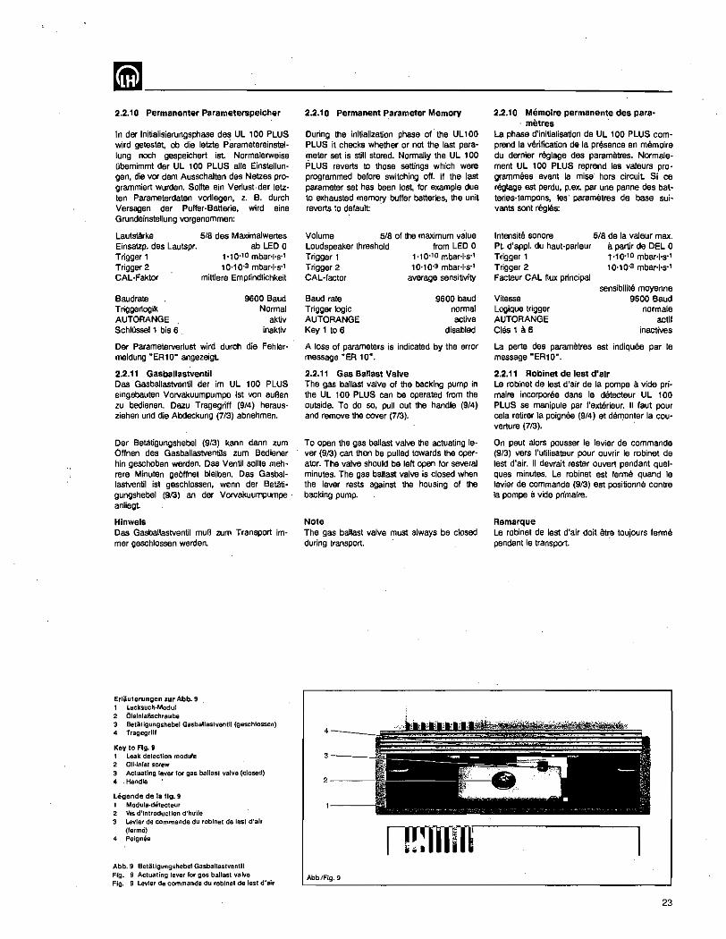
~--------~---------------2.2.10 Permanenter ParameterspelCher
In der Initialisierungsphase des UL , 00 PLUS wird getestet, ob die letzte parametereinstel· lung noch gespeichert ist. Normalerweise Obernimmt der UL 100 PLUS aile Einstellun· gen, die vor dam Ausschalten des Netzes programmiert wurden. Sonte ain Verlust-der letzten Parameterdaten vorliegen, z. B. durch Versagen der Puffer·Batterie, wird eine Grundeinstel1ung vorgenommen:
LautstArke Einsatzp. des Lautspr. Trigger 1 Trigger 2 CAL-Faktar
Baudrate Triggertogik AUTORANGE Schlussell bis 6
5/8 des Maximalwertas ab LED 0
1'10.10 mbar+s" 10-10.3 mbar+s"
mittlere Empfindlichkeit
9600 Baud Normal
aktiv inaktiv
Der Parameterverlust wird durch die Fehler· meldung "ER10" angezeigt
2.2.11 Gasballastventil Das Gasballastventil der im UL 100 PLUS eingebauten VOlVakuumpumpe ist von auBen zu bedienen. Dazu Tragegriff (9/4) herausziehen und die Abdeckung (7/3) abnehmen.
Oer Batatigungshebel (913) kann dann zum Offnen des Gasballastventils zum Bediener hin geschoben werden. Das Ventil sollte mehrare Minuten geOffnet bleiben. Das Gasballastventil ist geschlossen, wenn der Betatigungshebel (9/3) an der Vorvakuumpumpe· anliegt.
Hlnwels Das Gasba!lastventil muB zum Transport immer geschlossen werden.
Erliiuterungen zlAr Abb. 9 , Lecksucl!·Modul 2 OlelnlaBscl!raube 3 BeUUigungsllebel Gasballastventll (gaschtossen) 4 Tragegrlll
Key 10 FIg. 9 1 Leak detection module 2 OIl·lnfel screw 3 Acluatlng lever lor gas ballast valve (closed) 4 Handle
Legende de la fig. 9 1 Module·delectaur 2 Vis d'introduction d'hulle 3 levier de commande du robinat de lest d'alr
(ferme) 4 Poigmie
Abb.9 Betiitigungshebel Gasballsslventll Fig. 9 Actuating lever for gas ballast valve Fig. 9 Levier de commande dlA robine! de lasl d'air
2.2.10 Permanent P.arameter Memory
During the initialization phase of the Ul100 PLUS it checks whether or not the last parameter set is still stored. Normally the UL 100 PLUS reverts to those settings which were programmed before switching off. If the last parameter set has been lost, for example due to exhausted memory buffer batteries, the unit reverts to default:
Volume 5/8 of the maximum value Loudspeaker threshold from LED 0 Trigger 1 1010.10 mbar+s" Trigger 2 10'10.3 mbar+s·1
CAL-factor average sensitivity
Baud rate 9600 baud Trigger logiC normal AUTORANGE active Key1t06 disabled
A loss of parameters is indicated by the error message "ER 10".
2.2.11 Gas Ballast Valve The gas ballast valve of the backing pump in the UL 100 PLUS can be operated from the outside. To do so, pull out the handle (9/4) and remove the cover (7/3).
To open the gas ballast valve the actuating lever (913) can then be pulled towards the operator. The valve should be left open for several minutes. The gas ballast valve is closed when the lever rests against the housing of the backing pump.
Note The gas ballast valve must always be closed during transport.
3-__ _
2---
Abb.lFig.9
2.2.10 Memolre permanente des para-metres
La phase d'initialisation de UL 100 PLUS comprend la verification de la presence en memoire du dernier reglage des parametres. Normalemant UL 100 PLUS reprend les valeurs programmees avant la mise' hors circuit Si ce reglage est perdu, p.ex. par una panne des batteries-tampons, les· parametres de base suivants sont rE§gles:
Intensite sonore 5/8 de la valeur max. Pt d'appl. du haut-parleur a partir de DEL 0 Trigger 1 1'10.10 mbar+s" Trigger 2 10'10.3 mbar+s" Facteur CAL flux principal
sensibilite moyenne Vitesse 9600 Baud Logique trigger normale AUTORANGE actlf Chis 1 a. 6 inactives
La perte des parametres est indiquee par Ie message HER1 0".
2.2.11 Robinet de lest d'alr Le robinet de lest d'air de la pompa a vide prjmaire incorporee dans Ie detecteur UL 100 PLUS se manipule par I'extilrieur. II faut pour eela retirer la poignee (9/4) et demonter la couverture (713).
On peut alors pousser Ie levier de commande (9/3) vers I'utilisateur pour ouvrir Ie robinet de lest d'air. II devrait rester ouvert pendant quelques minutes. Le robinet est farme quand Ie levier de commande (9/3) est positionne contre la pompe a vide primaire.
Remarque Le robinet de lest d'air doit etre toujours ferme pendant Ie transport. .
23
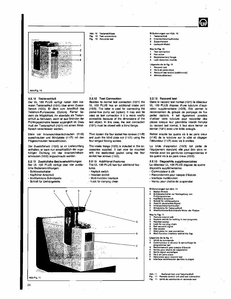
------------------~-----~
AbbJFlg.10
2.2.12 TestanschluB Der UL 100 PLUS verfOgt neben dam normalen TestanschluB (10/1) aber einen Zusatzflansch (10/3). Er dient zum AnschluB des Teilstrom-Pumpsatzes (Option). Ferner besteht die MOglichkeit ihn ebenfalls als TestanschluB lU benutzen, wenn ar aus GrOnden der PrOflingsgeomelrie besser zuganglich ist. Oazu muB der TestanschluB (10/1) mit einem Blindflansch verschlossen werden.
Dann vier Innensechskantschrauben (11/6) ausschrauben und Blindplatte (11n) mil den FIOgelschrauben herausdrOcken.
Dar Zusatzflansch (10/3) ist im Lieferumfang enthalten; ar kann nun einschlieBHch der 2ugeharigsn Dichtung mit vier Innensechskantschrauben (10/2) angeschraubt werden.
2.2.13 Zusatzllche Bedieneinrlchtungen Der UL 100 PLUS verfOgt Ober vier zusatzliche Bedieneinrichtungen: - SchlDsselschalter - Kopfhorer-AnschluB - Multifunktions-Schnittstelle - SchloB fOr Umhangekette
AbbJFig. 11
24
Abb. 10 TestanschHissa Fig. 10 Test connections Fig:. 10 Rllccords test
2.2.12 Test Connection Besides its ·normal test connection (1011) the UL 100 PLUS has an additional intake .port (1013). The latter is used for connecting the partial-flow pump set (option). It may also be used as test connection if it is more readily accessible because of the dimensions of the test object In this case, the test connection (lOll) must be closed with a blind flange.
Then loosen the four socket hex screws (11/6) and push the blind plate out (1117) using the four winged forcing screws.
The intake flange (1013) is included in ·the accessories supplied. II can now be mounted with the associated gasket using the four socket hex screws (10/2).
2.2.13 A~dltlonal Features The UL 100 PLUS has four additional features: - Keylock·switch - Headset socket - Multi-function Interface
. - Lock for carrying chain
5
~-----------------6
--------7 ------------------8
Erliuterungen zur Abb. 10 1 TestanschluB 2 Innensechskantschreube 3 Zusat.:llansch .. Lecksuch·Modul
Key to FIg.. 10 1 Test connection 2 Hel( screw 3 Supplementary lIange .. Leak detection module
Legende de la fig.. 10 1 Aaccord test 2 Vis a sil( pans creul( 3 Raccord test lateral (addltlonnel) 4 Module-detecteur
2.2.12 Raccord test Outre Ie raccord test normal (10/1) Ie detecteur UL 100 PLUS dispose d'une tubulure d'aspiration supplementaire (1013). Elle permet Ie raccordement du groupe de pompage de nux partiel (option). II est egalement possible d'utiliser cette tubulure pour raccorder des pieces lorsque leur geometrie interdit "emploi du raccord test normal. 11 faut alors fermer ce dernier (1011) avec une bride aveugle.
Retirer ensuite les Quatre vis a six pans creu)! (11/6) de la tubulure sur Ie cote et degager ,'obturateur (11n) avec vis a oreilles.
La bride - d'as:piration (1013) fait partie de I'equipement standard; elle peut etre alors reo montee avec les garnitures correspondantes el les quatre vis a six pans creux (10/2).
2.2.13 Dispositifs supplementaires Le detecteur UL 100 PLUS dispose de quatre dispositifs supplementaires: - Commutateur a cle - Raccordement pour casque d'ecoute - Interface multifonclion - Verrou pour chaine de suspension
Erliuterungen ~ur Abb. 11 1 Bedlen·Elnholl 2 Schlllssalschalter .:ur Verrlegelung von
PrUlprogrammon 3 1(0plh<Srer·AnschluB 4 SchloB IIIr Umhangekotte 5 Auslrltt akustisches Signal 8 Innensechskantschrauben 7 Blindpialle IIIr TestanschruB 8 Multifunklions·Schnlttstena hinter der I(lappa
Key to FIg. 11 1 Remote control unit 2 Keylock switch for locking In last programs 3 Headset sock.et .. Lock lor carrying chain 5 Exit acoustIc signal 6 Hel( scrows 7 Blind plate for test connection 8 Multl·lunctlon Interlace behind the flap
Ligende de 1a fig. 11 1 UnIte de commande . 2 Commutatour a cle pour Ie verroulllage de
programmes test 3 Raccordement pour casque d'ecoute 4 Verrou pour chaine de suspension 5 Sortie signal acoustique 8 Vis 8 sll( pans craUI( 7 Obturateur pour raccord test 8 Interface muttllonction dorriere Ie clapet
Abb. 11 Bedieneinheit und TestanschluB Fig. 11 Remote control unit and lest connection Fig. 11 Unite de commando el raccords test
mm ________________________ __ 2.2.13.1 SchlOsselschalter An de( Bedieneinheit <11/1) vom UL 100 PLUS 1st seitlich sin Schlusselschalter (11/2) angebracht.
Mit sechs verschiedenen SchWsseln lassen sich PrUfprogramme und Betriebsarten sinstellen.
Aktlvieren: • Entsprechenden SchlQssel in den Schlitz des
Schlusselschalters (11/2) der Bedieneinheit (11/1) bis zum Anschlag einschieben.
• Taste "ENTER" (4/13) betatigen. - Zero-Indikator LED (4/21) blinkt 3x lang.
• Schlussel abziehen.
Loschen: • Entsprechenden SchWssel in den Schlitz des
SchlOsselschalters (11/2) der Bedieneinheit (11Jl) bis zum Anschlag einschieben und anschlieBend Taste "ENTER'" (4/13)· betaligen.
- Null-lndikator LED (4/21) blinkt 6x kurz.
- SchlOssel abziehen.
Bairn Ausschalten des UL 100 PLUS werden die Eingaben, die Ober die SchlOsselfunktionen 1, 2 und 6 eingegeben wurden, abgespeichert, d.h. beim Wiedereinschalten erscheinen wieder die Zustande, die mit diesen SchlOsseln eingegeben wurden.
Die Funktionen, die mit SchlOssel 3, 4 und 5 eingestellt waren, werden beim Ausschalten nicht abgespeichert. Die Funktionen' der SchlOssel im einzelnen.
SchlUssel Nr. 1 SchlOssel Nr.1 verriegelt und entriegelt die Benutzung der Multifunktionstaste "Trigger und Kalibrierung" (4/11), um z. B. unbelugte Anderungen der eingestellten Kalibrierung und Triggerwerte zu verhindern.
Schliissel Nr.2 SchlOsser Nr.2 verriegelt und entriegelt Trigger, Kalibrierung, Hand, Auto und die Werteingabetasten.
SchlOssel Nr. 3 SchlOssel Nr. 3 wird nur in Verbindung mit dem Teilstrompumpsatz (Abschnitt 2.4.7.1) verwendet.
SchlUssel 3 ermOglicht bei automatischer Mel3bereichswahl die Umschaltung von FINE nach ULTRA. Hierbei wird das ext. Teilstromventil geschlossen und der Lecksucher arbeitet mit der maximalen Empfindlichkeit.
Die Umschaltung kann nur erfolgen, wenn der Einlal3druck p = 0,2 mbar unterschreitet.
Das Umschalten von ULTRA nach FINE ist nicht mOglich.
Schliissel Nr. 4 SchlOssel 4 ermOglicht die Lecksuche am Rezipienten mit eigener Vorvakuumpumpe ohne Verwendung des UL 100 PLUS-Pumpmoduls (6/5). Dazu 1st die Vakuumkupplung des Lecksuchmoduls (613) mit einem Blindflansch zu versehen und der Rezipient mit einem der TestanschlOsse zu verbinden.
2.2.13.1 Keylock Switch On the side of the UL 100 PLUS's remote control' unit <11/1) is a recessed keylock switch (11/2).
Six different keys can be used to enter test modes and operating modes.
Activating: - Insert the required key into the slit of the
key-operated switch (11/2) on the hand unit (11/1) right up to the stop.
- Operate "ENTER" (4113). - Zero indicator LED (4/21) flashes three
times (long). - Remove the key.
Deactivation: - Insert the required key into the slit of the
key-operated switch (11/2) on the hand unit (11/1) right up to the stop and then operate the RENTERH pushbutton (4f.13},
- Zero indicator LEO (4/21) flashes six times (briefly).
- Remove the key.
When switching off the UL 100 PLUS all entries entered through keys 1, 2 and 6 are stored, i.e.' when switching on again, the same conditions are set up.
Functions entered through keys 3, 4 and 5 are not stored when switching off. The effect of the keys is as follows.
Key No.1 Key No. 1 locks and unlocks the operation of the multi-function pushbutton "Trigger and Calibration" (4/11) for example to prevent unqualified changes in the calibration or trigger values.
Key No.2 Key No.2 locks and unlocks Trigger, Calibration; Manual, Auto and the parameter entry pushbuttons.
Key No.3 Key NO.3 is only used in connection with the partial flow pump set (see Section 2.4.7.1).
Key No. 3 permits switch over from FINE to ULTRA when the auto ranging process is on. When doing so, the external partial flow valve is closed and the leak detector is operated at its maximum sensitivity.
Switch over is only possible, provided'the inlet pressure is below p = 0.2 mbar.
Switch over from ULTRA to FINE is not possible.
Key No.4 Key No. 4 permits leak detection on objects with a backing pump without having to use the UL 100 PLUS pump module (6/5). For this purpose the vacuum connection on the leak detection module (613) must be equipped with a blind flange;- the test object is connected to one of the test connections.
2.2.13.1 Commutateur III cle Un commutateur a cle (1 1/2) est dispose dans un renfoncament sur Ie cOte de I'unite de commande (11/1) du detecteur UL lOa PLUS.
Six cles differentes permettent de ragler des programmes de verification et de modes de service.
Actlver: - Enfoncer la cle en question a fond dans la
fente du commutateur a cle (11/2) de I'unite de commande (11/1).
- Actionner la touche "ENTER" (4/13). - La DEL indicateur de zero (4/21) clignote 3x
(long). - Retirer fa cle.
Oesactiver. - Enfoncer la cle en question a fond dans la
fente du commutateur a cle (11/2) de I'unite de commande (1111) et actionner ensuite la touche "ENTER" (4/13).
- La DEL indicateur de zero (4/21) clignote 6x (court).
- Retirer la cia.
Quand UL 100 PLUS est mis hors circuit, il y a memorisation des donnees introduites par 'Ies cles " 2 et 6. Las etats introduits par cas cles apparaissent donc a nouveau a. la -remise en circuit.
Les fonctions reglees par les cles 3, 4 et 5 ne sont pas memorisees a la mise hors circuit Les diffl3rentes cles ont les lonctions suivantes.
Cle no. 1 La cle no. 1 verrouille et libere la touche multifonction "trigger et calibrage" (4/11), p. ex. pour empecher des modifications interdites du calibrage regie.
Cle no. 2 La cle no. 2 verrouille et libera les triggers, Ie calibrage, "Manualle", Auto, at les touches d'introduction de valaurs.
ele no. 3 La cle no. 3 ne s'utilise qu'en association avec Ie groupe de pompage a flux partiel (section 2.4.7.1).
La cle no. 3 permet la commutation de FINE vers ULTRA, en selection automatique des gammes de mesura. La robinet ext. flux partiel est ferme et Ie detecteur travailie avec la sensibillte maximale.
La commutation na peut avoir lieu que si la prassion d'admission tombs sous p '" 0,2 mbar.
La commutation de ULTRA VBrs FINE n'ast pas possible.
Cle no. 4 Elle permet la detection des fuites sur des objets ayant leur propre pompe primaire sans utiliser Ie module-pompe de UL 100 PLUS (6/5). EQuiper I'accouplement du vide du module detecteur (613) avec una bride aveugle et raccorder I'objet it. I'un des raccords test.
25
--------------------_____ mm Der Flutvorgang des Ul 100 PLUS kann nicht eingeleitet werden.
Urn in den Zustand "Betrieb ohne eigene Vorpumpa" zu gelangen, muB vcr dam Einschalten des UL 100 PLUS der SchlOssel NT. 4 ga-steckt saln. .
Dlase Lecksuchbetriebsart setzt voraus, daB am TestanschluB wahrend der gesamten Betriebsdauer des UL 100 PLUS sin Druck von Pe < 0,2 mbar herrscht
Nach dam Hochlauf kann im Zustand "STBY" der Schl0ssel NT. 4 wieder entfemt werden.
In der Betriebsart des UL 100 PLUS ohne Pumpmodul sind die Ventils Vl und V2 immer geoffnet, vorausgesetzt, der EinlaBdruck ist < 0,4 mbar.
Der Zustand "STANO-BY" unterscheidet sich vorn Zustand "MEAS" dadurch, daB die Leekratenanzeige ausgescha/tet ist. Oberschreitet der Einla1k1ruck den Wert 0,4 mbar. wird Vl automatisch geschlossen. die lonenquelle abgeschaltet und auf dam Statusdisplay die Fehlermeldung "ER01" (max. Vorvakuumdruck Oberschritlen) angezeigt
Zur Wiederaufnahme des Leeksuchbetriebes ohne Pumpmodul ist in diesem Fall das UL 100 PLUS-Lecksuchmodul auszuschalten und dann erneut mit eingestecktem SchlOssel Nr. 4 in Beuiab zu nahmen.
SchlUssel Nr. 5 'SchlOssel Nr. 5 ermoglicht das Messen von Leeks bei einem EinlaBdruck von PE < 100 mbar mit einer beliebigen externen Vorpumpe.
Der UL 100 PLUS ist somit in der Lage, ein Autoranging far MeBwerte von 10 mbar+s" bis 1'10.9 mbar+s-1 durchzufOhren, in AbhAngigkeit vom SaugvermOgen der Vorvakuumpumpe.
Zur Aktivierung den SchlOssel Nr. 5 in den SchlUsselschlitz der Bedieneinheit stacken und im STBY·, VENT- oder MEAS-Mode des UL , 00 PLUS die Taste "ENTEW drOcken.
Diese Funktion kann durch erneutes Aufrufen wieder aufgehoben werden. Danach geht der UL 100 PLUS in den STAND-By-Zustand.
Mit dam Abschalten des UL 100 PLUS (Netzschalter (917) auf Stellung "AUS") wird diese Funktion aufgehoben und nicht gespeichert.
Far den Einsatz in automatischen PrCtfsystemen braucht der SchlOssel Nr. 5 nur gesteckt sein, da er direkt nach dem Einschalten automatisch registriert wird.
Be; Verwendung des Standard-Teilstrompumpsatzes darf der SchlOssel Nr .. 5 nicht ak· tiviert werden, da ansonsten das Teilstrom· ventil nicht angesteuert wird.
Bei aktivem SchlOssel 5 kann der Rezipient nicht durch den UL 100 PLUS geflutet wer· den.
SchlOssel Nr. 6 Der SchWssel Nr. 6 ei moglicht den SchnOffel· belrieb.
26
. The venting process of the UL 100 PLUS can not be initiated.
Key No. 4 must be inserted before switching on the UL 100 PLUS when wanting to enter the operating mode "Operation without built-in backing pump".
For this leak detection mode it is required that during the entire process an inlet pressure PE of < 0.2 mbar is maintained at the test connection 01 the UL 100 PLUS.
After run-up. key. No. 4 may be removed when the unit has entered the "STBY" mode.
In the operating mode of the UL 100 PLUS without pump module valves V1 and V2 reo main always open, provided the inlet pressure is continuously below 0.4 mbar.
The "STAND·BY" condition differs from the "MEAS" condition in that the leak rate display is switched off. Should the inlet pressure exceed the value 0.4 mbar V1 is automatically closed and the ion source is switched off; the status display will then indicate "ER01" (max. forevacuum pressure exceeded).
In order to return to the operating mode without the pump module, the leak detection mo· dule must be switched off in this case and again put into operation using key NO.4.
Key No.5 Key No.5 allows the measurement of leaks at an inlet pressure of PE < 1 00 mbar in connection with any backing pump.
The UL 100" PLUS is thus placed in a position for autoranging in the 10 mbar+s-1 to 1'10.9 mbar+s·1 range, depending on the volume flow rate of the backing pump.
For activation key No. 5 is inserted into key slot on the operating unil Then the "ENTER" pushbutton is operated while the UL 100 PLUS is in the STBY, VENT or MEAS mode.
This function can be cancelled by calling up this function again. After having done so, the UL 100PLUS reverts to the STANDBY mode.
When switiching off the UL 100 PLUS (mains switch (Sn) in position "OFF") this function is cancelled and not stored.
For applications in automatic testing systems it is only required to insert key No.5, as its presence is automatically detected upon switching on.
When using the standard partial flow pump set key No.5 must not be activated as otherwise the partial flow valve will not function.
With key No. 5 active, the vacuum chamber cannot be vented by the UL 100 PLUS.
Key No.6 Key NO.6 enables the sniffer mode.
II n'est pas possible de pratiquer une remise a I'air dans UL 100 PLUS.
Pour obtenir I'etat "service sans module·pompa primalre", i1 faut enfoncer la cle no. 4 avant de mettre UL 100 PLUS en circuit
Ce mode de detection necessite une pression de PE < 0,2 mbar au raccord test pendant toute la duree du service de UL 100 PLUS.
Apres' la montee en regime la cle no. 4 paut eire retiree quand ,'unite est dans Ie mode "STBY",
Dans Ie mode de service de UL 100 PLUS sans madule-pompe les robinets V, at V2 sont toujours ouverts a condition que la pression d'admission soit < 0,4 mbar.
L'atat "STAND-BY" sa dlstingue de I'etat "MEAS" par la decommutation de I'affichage de taux de fuite. Lorsque la pression d'admission depasse la valeur 0,4 mbar, V1 est ferma automaliquement, la source d'lons d8connectae at Ie message d'erreur "ER01" (pression primaire max. depassee) est indique dans I'affichage d'etat).
Pour revenir en mode detection sans module· pompe, i1 faut arr~r dans ce cas Ie moduledetecteur de UL 100 PLUS et Ie remettre en service apres avoir enfonce la cle no. 4.
Cle no. 5 Elle permet la mesure de fuites pour une pression d'admission de Pe< 100 mbar avec une pompe primaire externe quelconque.
Le detecteur UL 100 PLUS est ainsi en me· sure d'effectuer une fonction auto range pour des valeurs de mesure de 10 mbar+s·1 a 1'10-g mbar+s" en fonction du debit de la pompe a vide primaire.
Pour activer, enfoncer la cle no. 5 dans la fente de I'unite de commande at actionner la touche "ENTER" quand UL 100 PLUS est en mode STBY, VENT ou MEAS.
Cette fonction paut eire supprimee ou bier reactivee par nouvel appel. UL , 00 PLUS passe ensuite a I'etat STAND-BY.
En mettant Ie detecteur UL 100 PLUS hon service (I'interrupteur (8/7) sur la positior "ARRET") cette fonction est supprimee et pa: mise en memoire.
Pour Ie service dans des contreles automa tiQues la cle no. 5 doit seulement eire enfon cee, etant automatiquement enregistree im mE!diatement apres mise en service.
Si un groupe de pompage a flux partiel stan dard est utilise, la cle no. 5 ne doit pas etr activee car Ie robinat de flux partiel ne sera pas commande.
Quand la cle 5 est activee, I'objet ne peut plu ~tre remis a.l'atmosphere par UL 100 PLUS.
Cle no. 6 Elle permet Ie service renifleur.
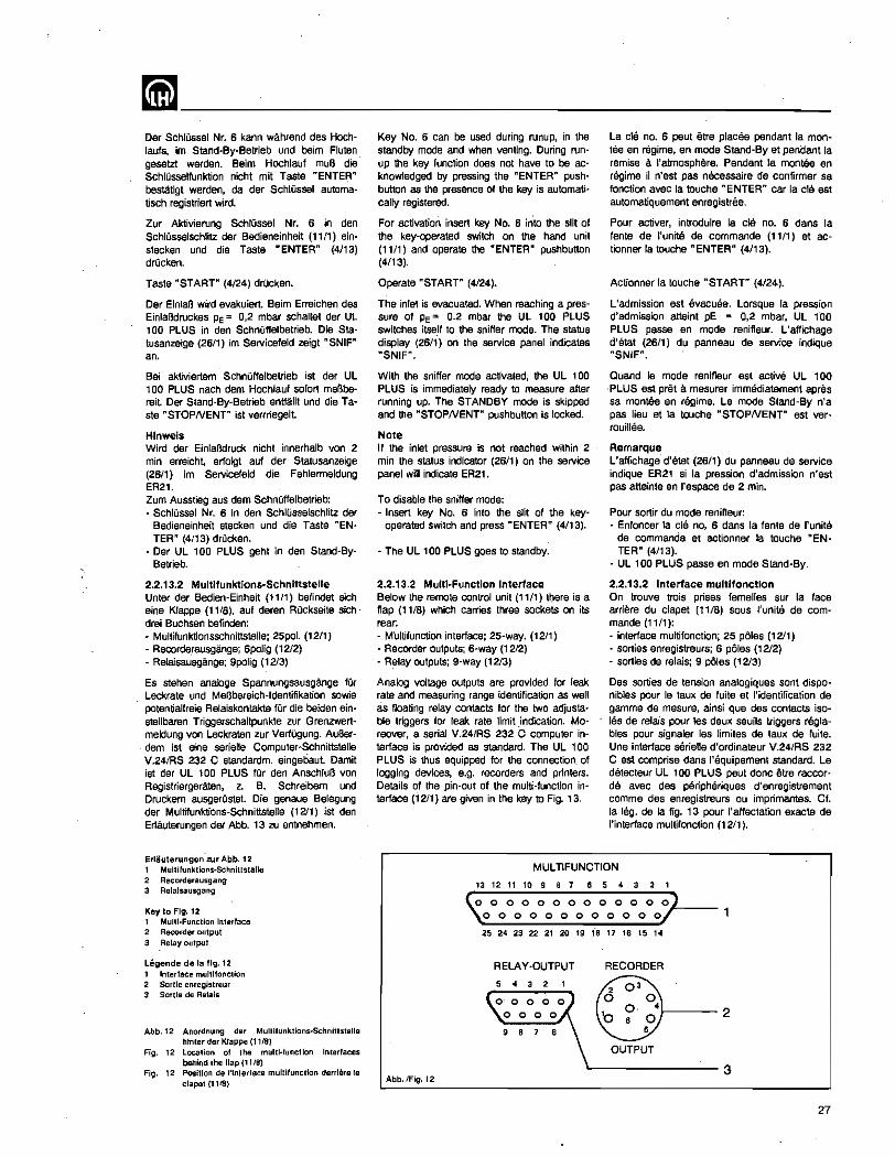
mm ________________________ __ Oer SchlQssel Nr. 6 kann wahrend des Hochtaufs, 1m Stand-By-Betrieb und baim Fluten gesetzt werden. Bairn Hochlauf mull die Schlusselfunktion nicht mit Taste "ENTE~" bestatigt werden, da der Schlossel automatisch registriert wird.
Zur Aktivierung SchlOssel Nr. 6 in den SchlOsselschlitz der Bedieneinheit (11/1) 8instecken und die Taste "ENTER" (4/13) drOcken.
Taste "START" (4/24) drOcken.
Der EinlaB wird 8vakuiert. Bairn Erreichen des EinlaBdruckes PE'" 0,2 mbar schaltet der UL 100 PLUS in den SchnOffelbetrieb. Die Statusanzeige (26/1) im Servicefeld zei9t "SNIF" an,
Bei aktiviertem SchnOffelbetrieb ist der UL 100 PLUS nach dam Hochlauf sofart mel'3bereil. Der Sland-By·Setrieb entMilit und die Taste .. STOPNENT" ist vemiegelt.
Hlnweis Wird der Einlalklruck nicht innerhalb von 2 min erreicht, erlolgt auf der Statusanzeige (26/1) im Servicefeld die Fehlermeldung ER21. Zum Ausstieg aus dem SchnOffelbelrieb: - SchlOssel Nr. 6 in den SchlOsselschlitz der
Bedieneinheit stecken und die Taste REN· TER w (4/13) drOcken,
- Der UL 100 PLUS geht in den Stand'By-Betrieb.
2.2.13.2 Multlfunktions·Schnittstelle Unler der Bedien·Einheit (11/1) befindet sich eine Klappe (11/8), auf deren Ruckseite sich· drei Buchsen befinden: - Multifunktionsschnittstellej 25pol. (12/1) - Recorderausgange; 6poJig (12/2) - Relaisausgange; 9polig (1213)
Es stehen analoge Spannungsausgange fUr Leckrate und Mel3bereich-ldentifikation sowie potentialfreie Relaiskontakte fUr die beiden ein· stellbaten Triggerschaltpunkte zur Grenzwertmeldung von Leckraten zur VerfOgung. AuBerdem ist eine serielte Computer·Schnittstelie V.241RS 232 C standardm. eingebaut. Damit ist der UL 100 PLUS fOr den Anschlul3 von Registriergeraten, z. B. Schreibem und Druckem ausgerOstet. Die genaue Belegung der Multifunktions-Schnittstelle (12/1) ist den Erlauterungen der Abb. 13 zu entnehmen.
Erliiuterungen lur Abb. 12 1 Mullilunktions-Schnittstelle 2 Recorderausgang 3 Relalsausgang
Key to Fig. 12 1 Multl·Function Interlace 2 Recorder output 3 Relay output
Legende de la Ilg. 12 1 Inlerlace mullilonction 2 Sortie enregislreur 3 Sortie de Relais
Abb.12 Anordnung der MulUlunktlons·Schnlttslelle hlnler der Klappe (11181
Fig. 12 Location 01 the multl·functlon Interlaces behind the !lap (11/8)
Fig. 12 Position de l'lnlerlace mul!iluncllon derriere fe clapet (1118)
Key No. 6 can be used during runup, in the standby mode and when venting. During runup the key function does not have to be acknowledged by pressing the "ENTERR pushbutton as the presence of the key is automatically registered.
For activation insert key No. 6 into the slit of the key-operated switch on the hand unit (11/1) and operate the "ENTER" pushbuttM (4113),
Operate "START" (4/24).
The inlet is evacuated. When reaching a pressure of PE"" 0.2 mbat the UL 100 PLUS switches itse.lf to the sniffer mode. The status display (2611) on the service panel indicates "SNIF",
With the sniffer mode activated, the UL 100 PLUS is immediately ready to measure after running up. The STANDBY mode is skipped and the "STOPNENTR pushbutton is locked.
Note If the inlet pressure is not reached within 2 min the status indicator (26/1) on the service panel will indicate ER21.
To disable the sniffer mode: - Insert key No. 6 into the slit of the key
operated switch and press "ENTER" (4/13),
- The UL 100 PLUS goes to standby.
2.2.13.2 Multi-Function Interface Below the remote control unit (11/1) there is a flap (11/8) which carries three sockets on its rear: - Multifunction interface; 25-way. (1211) - Recorder outputs; 6·way (12/2) - Relay outputs; 9-way (12/3)
Analog voltage outputs are provided for leak rate and measuring range identification as well as floating relay contacts for the two adjustable triggers for leak rate limit .indication. Moreover, a serial V.24/RS 232 C computer interface is provided as standard. The UL 100 PLUS is thus equipped for the connection. of logging devices, e.g. recorders and printers. Details of the pin-out of the multi-function interface (1211) are given in the key to Fig. 13.
La cle no. 6 peut etra places pendant la mantee en regime, en mode Stand-By et pendant la remise a I'atmosphere. Pendant la mantee en regime il n'est pas necessaire de confirmer sa fonctlon avec la touche "ENTER" car [a cia est automatiquemerit enregistree.
Pour activer, lntrodulre 18 cle no. 6 dans la fente de I'unite de commande (11/1) et actionner la touche "ENTER" (4/13).
Actionner la touche "START" (4/24).
L'admission est evacuee. Lorsque [a pression d'admission attaint pE "" 0,2 mbar, UL 1'00 PLUS passe en mode renifleur. L'affichage d'etat (26/1) du panneau de service indique "SNIF",
Quand Ie mode renifleur est active UL 100 PLUS est pret a mesurer immediatement apres sa montee en regime. Le mode Stand-By n'a pas lieu et la touche "STOPNENT" est ver(ouillee.
Remarque L'affichage d'etat (26/1) du panneau de service indique ER21 si la pression d'admission n'est pas attainte en I'espace de 2 min.
Pour sortir du mode renifleur: - Enfoncer la cia no .. 6 dans la fente de I'unite
de commande et actionner la touche "ENTER" (4113),
- UL 100 PLUS passe en mode Stand-By.
2.2.13.2 Interface multifonctlon On trouve trois prises femelles sur la face arriere du clapet (11/8) sous I'unite de commande (11/1): • interface multifonctionj 25 poles (1211) - sorties enregistreurs; 6 poles (1212) - sorties de relais; 9 poles (12/3)
Des sorties de tension analogiques sont dis ponibles pour Ie taux de fuite et I'identification de gamme de mesure, ainsi que des contacts isoles de telais pour les deux sauils triggers reglables pour signaler les limites de laux de fuite. Une interface serielle d'ordinateur V.24/RS 232 C est comprise dans I'equipement standard. Le detecteur UL 100 PLUS peut done eire raccor· da avec des peripheriques d'enregistrement comme des enregistreurs ou imprimantes. Cf. la leg. de la fig. 13 pour I'affectation exacte de I'interface multifonction (1211).
MULTIFUNCTION
13 12 11 10 9 8 7 6 5 4 3 2 1
(0 0 0 0 0 0 0 0 0 0 0 0 0,.) __ _
\0 0 0 0 0 0 0 0 0 0 0 0/
25 24 23 22 21 20 19 18 17 16 15 14
RELAY-OUTPUT RECORDER
r----2
OUTPUT
'--------3 Abb. !Fig. t 2
27

----~------~---~
13 12 " 10 9 8 7 8 5 4 3 2 1
\.0 0 0 0 0 0 0 0 0 0 0 0 0) ~o 0 0 0 0 0 0 0 0 0 0 0)'
25 24 23 22 21 20 19 18 17 18 15 14
Abb.13 Mulillunkiions-Ausgang Fig. 13 Multl·functlon output Fig. 13 Sortie mullilonclion
Waiters Beschreibung der einzelnen Signale fur die serislls Computer-$chnittstelle (1211) sowie Beschreibung der Betriebsarten REMOTE und PRINT ONLY siehe Schnittstellenbeschreibung S8 10.207.
z'usatzAch zu diesar Multifunktions-Schnittstelle befindet sich parallel sine Spoi. Schnittstellenbuchse (1213) auf der. "OChmars die vier RelaisausgAnge und die RecorderausgAnge geschaltet sind. Entsprechende Steckerbelegung siehe Abb. 14. Der separate Recorderausgang (12/2) liegt 8uch parallel zu den beiden vorgenannten Schnittstellenbuchsen. Entsprechende $teckerbelegung siehe Abb. 15.
2.2.13.3 Trlgger·Ausgange Trigger 1 +_,2. Zur extemen Ansteuerung von Grenzwertmel· dern z. B. "GUT" I "SCHlECHT"·Anzeigen sind 2 Triggerausgange (siehe Abschnitt 2.2.8.1) vorgesehen als potentialfreie Relais· kontakte. Zur Programmierung und Funktion der Trigger-AusgAnge siehe Abschnitt 2.2.8. Die Relaiskontakte sind herausgefUhrt auf der Multifunktionsbuchse und der. Relais·Aus· gangsbuchse mit folgender Belegung:
Standarcl·loglk (Funktlon Normal) Multifunktions-Schnittstelle (1211) bzw'.Abb13: PIN Nr. 10 und 11 schliel3ender Relaiskon
takt von Trigger 1 PIN Nr. 12 und 13 schliel3ender Relaiskon
takt von Trigger 2 Relaisausgang (1213) bzw. Abb 14: PIN Nr. 2 und 3 schliel3ender Relaiskon
takt von Trigger 1 PIN Nr. 4 und 5 schliel3ender Relaiskon
takt von Trigger 2
RELAY-OUTPUT
5 4 3 2 1
~oOoOoOo'l 9 8 7 6
Abb.14 Relalsausgang Fig. 14 Relay oulput Fig. 14 Sortie de relals
28
Erliuterungen zur Abb.13 Key to FIg. 13 1 frel 1 not used
Litgende de 101 fig. 13 1 Llbre
2 RXO 2 RXD 2 RXe 3 TXO 3 TXO , TXD 415 frel 415 not used 415 Llbres 6 DSR 6 DSR 6 OSR 7 GNO 7 GNO 7 GNO
~~ ~r~~~::~~lals'AUSgtinge! ~~ ~~;:!rUf(Relay outputs) 11 Trigger 1 (Relals·Ausgtinge 11 Trigger 1 (Relay outputs) 12 Trigger 2 (Relals·Ausgiinge 12 Trigger 2 (Relay outputs)
819 Libres 10 Trigger 1 (sorties de relais) 11 Trigger 'Jsortles de relais) 12 Trigger 2 sorties de relais)
~~ §~~uge~~~J~~lf~1;~~~~~~lye) ~~ ~~fr:i ~!~1!f~,g~te~::! 15 Bezugsmasse IIlr 14 15 Reference ground 'or 14
13 Triggar 2 sorties de relais) 14 Comman e robinet flux partie
~~ ~e~::ndUef~~~rcirur 14 HI 24 V Verso fUr 17 16 24 V versIon for 17 11 Teilstromventil RlIckmeldung 17 Partlal·flow·Valve status Ind. 18 PumpenlFluten 18 Pumpingl venting (Rem.
17 Robinel 18 Evacuer/remellre a I'alr
(telecommande) 19 20 21
(Fernsteuerung) control) StandBy/FlutenFernsteuerung) 19 Standbytvenllng (Rem. control) frel 20 not used
t9 Stand·by/remaUre 11 I'alr(telecommande)
~~Z~&1~nads~;rumpen I Flu· 21 ~:~rr:;,C~t~~~~ny~ {pumping I 22 Leckratenslgna' 22 Helium signal
20 Llbre 21 Masse de reference (evacuerf
remellre a l'airfStand·by) 23 :V~~~trICh.::~.~!'i .(Exponent) 23 :ve=~W3~~'!I~s'!9~ signal
9V = 10'W mbar+s·1 9V '" 10·To-mbar+s·1
22 Signal helium 23 Signel gamme de mesure Ifx,
24 ElnlaBdruck (PI!I) 24 Inlet pressure (Pel 25 Bezugsmasse \L.eckratenslgnal 25 Reference grounCl (leak rate
~~s~nlh~YK':n'bO~r.rs~fl"'s· , 24 Pression d'admlsslon (pe)
lMe8berelch·Slgnal . :[g~:~measurement range 25 Massa de reference (signal taux de lulie/signal gamme de mesure)
Further description of the single signals for the serial computer interlace (12/1) as well as the description of the operating modes REMOTE and PRINT ONLY see instructions for the interlace SB 10.207.
In addition to this multifunction interface there is a parallel g-way interface socket which du~ plicates the four relay outputs and the recorder outputs. The pin-out of this socket is given in Fig. 14. The separate recorder (12/2) output is in parallel to the aforementioned interface sockets. The pin-out of this socket is given in Fig. 15.
2.2..13.3 Trigger Outputs Trigger 1 + 2 Two trigger outputs (see section 2.2.8.1) with floating relay contacts are provided for con· nection to external limit value indicators such as for ex. "PASSED" 1 "REJECTED". For programming and operation of the trigger out· puts see Section 2.2.8. The relay contacts are accessible through the multHunction socket and the relay output socket, whereby the fol· lowing pin assignment applies.
Standard logic (Function normal) Multi-function interface (12/1) and Fig. 13: PIN No. 10 and 11 normally closed relay
contact of trigger 1 PIN No. 12 and 13 normally closed relay
contact of trigger 2 Relay output (1213) and Fig. 14: PIN No.2 and 3 normally closed relay
conlact of trigger 1 PIN NO.4 and 5 normally closed relay
contact of trigger 2
ErUiuterungen zur Abb. 14 1 nicht belegen
Key to Fig. 14 1 do not use
Voir la description d'interlace SB 10.207 pOl plus d'informations sur les differents signal; pour I'interlace senelle d'ordinateur (12/1) E
sur les modes de service REMOTE et PRIN' ONLY.
Outre cette interface mUltifonction on trouVE parallelement, une prise interface 9 pale (12/3) foumissant encore une lois les quatr sorties de (elais et les sorties enregistreur. POl les affectations voir la fig. 14. la sortie enregi~ treur separee (12/2) est egalement parallel aux deux prises interfaces preoitees. Pour Ie affectations voir la fig. 15.
2.2.13.3 Sorties trigger 1 et trigger 2 Deux sorties trigger (voir section 2.2.8.1) contacts isoles de relais sont prevues pour r connexion avec des indicateurs de valeur limit p. ex. "BON" I "REJETEn. Voir la sectio 2.2.8 pour la programmation et la fonction de sorties triggers. les contacts de relais sont sal tis sur Ie connecteur multifonction at la prise d sortie de relais avec les affectations suivantes:
Logique standard (fonctlon normale) Interface multifonction (1211) ou fig. 13: PIN No. 10 et'1 contact de travail du
trigger 1 PIN No. 12 et 13 contact de travail du
trigger 2 Sortie relais (12/3) au fig. 14: PIN No.2 et 3 contact de travail du
trigger 1 PIN No.4 et 5 contact de travail du
trigger 2
Legende de la Ilg. 14 1 L1bres
2 Trigger 1 (Relals.Ausgange) a Trigger t (Relals·Ausgange) 4 Trigger 2 (Rel .. ls·Ausgtinge) 5 Trigger 2 (Relals·Ausglinge) 6 Leckretensignal
2 Trigger 1 (Releyoutputs) 3 Trigger 1 (Relay outputs) 4 Trigger 2 (Relay outputs) 5 TrIgger 2 (Relay outputs) 6 Leak rate signal
Trigger 1 (sorties de relals) Trigger 1 (sorties de relals)
4 Trigger 2 (sorUes de relais) 5 Trigger ;Z (sorties de relais) 6 Signa' t .. ux de fuile
7 MeBbereich-Slgnal (Exponent)
OV=100 mbar+s-'. QV = 10.10 mbar+s-'
8 EinlaBdruck (pe) 9 Bezugsmasse
(Leckratensignafl Treppenspannung)
7 Measurement range (exponant)
OV=100 mbar+s·1• 9V = 10.10 mbar·!-s·1
8 Inletpr8SSure (PE) 9 Reference ground (Leak rate
signa' I staircase voltage)
7 Signal gamme de mesure (exprisant) OV= 100 mbar+s", 9V ,. '0.10 mbar+s·1
6 Presslon d'admi!05lon {pel 9 Masse de reference (signal tau)
de fuile/tension echelonnee)
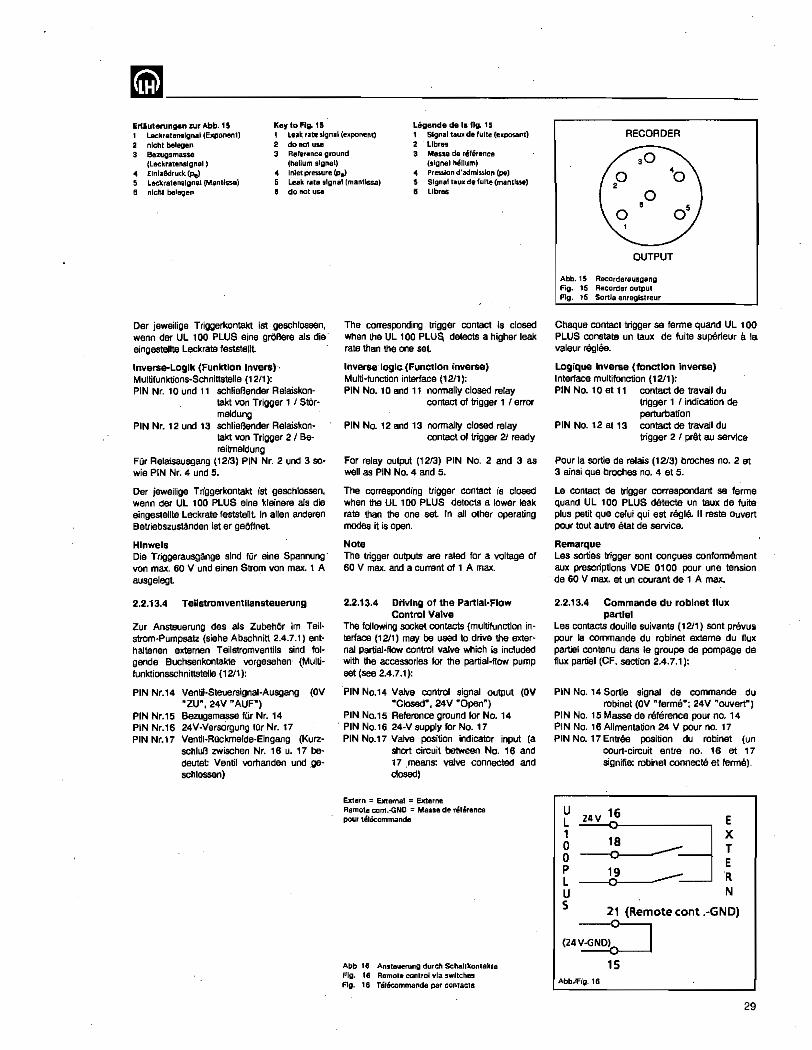
~-------------------------Erlluterungen zur Abb. 15 Key to FIg. 15 Legende de Ie fig. 15 1 Leckra,enslgnal (Exponent) 2 nlchl Delegen
1 leak ratestgnal (e~ponent) 2 do not use
1 Slgnallau~ defulte (e_posant) 2 Libras
3 Bezugsmasse 3 Reference ground 3 Masse de reference (Lackralenslgoal ) ElnlaBdruek. <Pel Leckralenslgnal (Mantissa) nlchl belegen
(helium signal) (signal helium) of Inletpressure(Pel .. Preulon d'admlsslon (pe) 5 Leak rale signal (mantissa) 6 do not usa
5 Sigoilll,au_ de tulte (mantlsse) 6 Libras
Der jeweilige Triggerkontakt ist geschlossen, wenn dar UL 100 PLUS aine graBere a1s die eingestellte leckrate feststeUt
Inverse-Logik (Funktion Invers)-· Muitifunktions-Schnittstelie (12/1): PiN Nr. 10 und 11 schlieBender Relaiskon
takt von Trigger 1 I Starmeldung
PIN Nr. 12 und 13 schlieBender Relaiskontakt von Trigger 2 / Bereitmeldung
Fur Relaisausgang (12f3) PIN Nr. 2 und 3 sowie PIN Nr. 4 und 5.
Der jeweilige Triggerkontakt ist geschlossen, wenn der UL 100 PLUS eine kleinere als die eingestellte Leckrate feststerrt In allen anderen Betriebszustanden ist er geOffnet
Hinwels Die Triggerausgange sind fUr eine Spannung" von max. 60 V und einen Strom von max. 1 A ausgelegt
2.2.13.4 Tellstromventllansteuerung
Zur Ansteuerung des als ZubehOr 1m Teilstrom-Pumpsatz (siehe Abschnitt 2.4.7.1) enthaltenen externen Teiistromventils sind 101-gende Buchsenkontakte vorgesehen- (Multifunktionsschnittstelle (1211):
PIN Nr.14 Ventil-Steuersignal-Ausgang (OV "ZU", 24V "AUF")
PIN Nr.15 Bezugsmasse fUr Nr. 14 PIN Nr.16 24V-Versargung fur Nr. 17 PIN Nr.17 Ventil-Ruckmefde-Eingang (Kurz
schluB zwischen Nr. 16 u. 17 bedeutet Ventil vorhanden und ,geschlossen)
The corresponding trigger contact is closed when the Ul 100 PlUa, detects a higher leak rate than the one set
Inverse' loglc_ (Function inverse) Multi-function interface (1211): PIN No.1 0 and 11 normally closed relay
contact of trigger 1 I error
PIN No. 12 and 13 normally closed relay contact of trigger 21 ready
For relay output (1213) PIN No. 2 and 3 as well as PIN No.4 and 5.
The corresponding trigger contact is closed when the UL 100 PLUS detects a lower leak rate than the one set In all other operating mooes it is open.
Note The trigger outputs are rated for a voltage of 60 V max. and a current of 1 A max.
2.2.13.4 Driving 01 the Partial-Flow Control Valve
The following socket contacts (multifunction interface (1211) may be used to drive the external Partial-flow control valve which is included with the accessories for tha partial-flow pump set (see 2.4.7.1):
PIN No.14 Valve control signal output (OV "Closed", 24V "Open")
PIN No.15 Reference ground for No. 14 . PIN No.16 24-V supply for No. 17
PIN No.17 Valve position indicator input (8 short circuit between No. 16 and 17 means: valve connected and closed)
Extern ::: External;; Externe Remote cont.-GNO = Masse de reference pour tel&c:ommanda
Abb 18 Anstellerung durch Schaltkontakte Fig. t6 Remote control via switches Fig. 16 Telecommande par contacts
RECORDER
,0 '0
,0
OUTPUT
Abb.15 Reoorderallsgang Fig. 15 ReCOrder output Fig. 15 Sortie enreglstreur
Chaque contact trigger sa ferme quand UL 100 PLUS constate un taux de fuite superieur a la valeur reglee.
Logique inverse (fondlon Inverse) Interface multifonction (12/1): PIN No.1 0 at 11 contact de travail du
trigger 1 I indication de perturbation
PIN No. 12 et 13 contact de travail du triggar 2 I pr€lt au service
Pour la sortie de ralais (12f3) broches no. 2 at 3 ainsi que brochas no. 4 at 5.
Le contact de trigger correspondant se ferma quand UL 100 PLUS detecte un taux de fuite plus petit que celui qui est regie. II reste ouvert pour tout autre elat de service.
Remarque Les sorties trigger sont conc;ues conformement aux prescriptions VDE 0100 pour une tension de 60 V max. at un courant de 1 A max.
2.2.13.4 Commande du roblnet 11ux partlel
les contacts douille suivants (1211) sont prilvus pour la commande du robinet externe du flux partiel contenu dans Ie groupe de pompage de flux partiel (CF. section 2.4.7.1):
PIN No. 14 Sortie signal de commande du robinet (OV "ferma"; 24V "oovert")
PIN No. 15 Masse de reference pour no. 14 PIN No. 16 Alimentation 24 V pour no. 17 PIN No. 17 Entree position du robinet (un
court-circuit entre no. 16 at 17 signifie: rabinet connecte et terms).
U 24V 16 E
!l :::~i u N S 21 (Remote cant .-GNO)
(24;;:J
15 Abb.IFig. 16
29
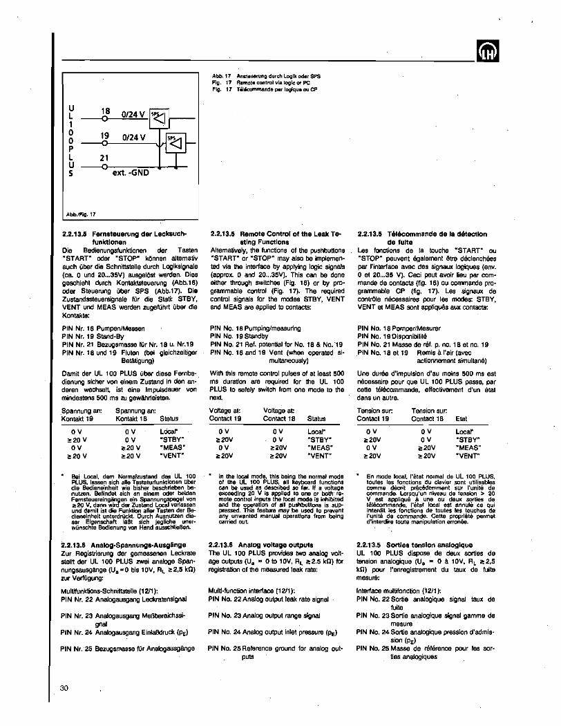
----------~----------~--~
U L 1 0 19 0/24 V 0 P L 21 U 5 ext. -GND
Abb.lFlg.17
2.2.13.5 Fernsteuerung der Lecksuch-funktlonen
Die Bedienungsfunktionen der Tasten "STAAT" oder "STOP" kOnnen a1temativ auch aber die Schnittstelle durch Logiksignate (ca. 0 und 20 ... 35V) ausgelOsl werden. Dies geschieht durch Kontaktsteuerung (Abb.16) oder Steuerung aber SPS (Abb.17). Die Zustandssteuersignale fOr die Stati: STBV, VENT und MEAS werden zugefOhrt Qber die Kontakte:
PIN Nr. 18 PumpenJMessen PIN Nr. 19 Stand-By PIN Nr. 21 Bezugsmasse fOr Nr. 1 S u. Nr.' 9 PIN Nr. 18 und 19 Fluten (bel gleichzeitiger
Betatigung)
Damit der UL 100 PLUS aber diese Fernbe· dienung sicher von einem Zustand in den an· deren wechsett. 1st aine Impulsdauer von mindestens 500 rna 2U gewAhrieisten.
Spannung an: Spannung an: Kontakt 19 Kontakt 18 Status
OV OV Local' 0!:20V OV oSTBY"
OV 0!:20V "MEAS" !:20V ~20V "VENT"
Bel local, dem Normalzustand des Ul 100 PLUS, lassen sich aile Tastalurlunktlonen Ilber die Bedieneinheit wie bishar baschrleben benutten. Bellndet sich an einem odar beiden Fernsteuereingangen eln Spannungspegel von ~20 V, dann wird der Zustand Local verlassen und damit 1st die Funktion aller Tasten der Bedieneinheit unterdrllckt. Durch Ausnutzen dieser Eigenschaft laBt sich jegliche unerwQnschle Bedlenung von Hand ausschlleBen.
2.2.13.6 Analog-Spannungs-Ausginge Zur Registrierung der gemessenen Leckrate stallt der UL 100 PLUS zwei analoge Spannungsausginge (Ua"'O bis 10V, RL 2:2.5 kn) zur VerfOgung:
Multifunktions-Schnittstelle (1211): PIN Nr. 22 Analogausgang Leckratensignal
PIN Nr. 23 Analogausgang MeBbereichSSi-gnal
PIN Nr. 24 Analogausgang EinlaBdruck (Pe)
PIN Nr. -25 Bezugsmasse fUr Analogausgange
30
Abb.11 Ansleuerung dllrch Loglk oder SPS Fig. 17 Rllmole conlrol via logic or PC Fig. 11 i.lecommande par loglqlle au CP
2.2.13,5 Remote Control of the Leak Te-8tlng Functions
Altematively. the functions of the pushbunons "STAAT" or "STOP" may also be implemented via the interlace by applying logic signals (approx. 0 and 20 ... 35V). This can be done either through switches (Fig. 16) or by programmable control (Fig. 17). The required control signals for tha modes STBY, VENT and MEAS are applied to contacts:
PIN No. 18 Pumping/measuring PIN No. 19.5tandby PIN No. 21 Ref. potential for No. 18 & No. '19 PIN No. 18 and 19 Vent (when operated si-
multaneously)
With this remote control pulses of at least 500 ms duration are required for the UL 100 PLUS to safely switch from one moda to the next.
Voltage at: Voltage at ContaCt 19 Contact 18 Status
OV OV Loca~
2:20V OV oSTBY" OV 2:20V "MEAS"
2:20V ~20V "VENT"
In the local mode, this being trye normal mode of the Ul 100 PLUS. all keyboard functions can be used as described so far. II a voltage exceeding 20 V is applied to one or both' remote control inputs the local mode is inhibited and the operation 01 all pushbuttons Is suppressed._ This feature may be used to prevent any unwanted manual operations from being carried out.
2.2.13.6 Analog voltage outputs The UL 100 PLUS provides two analog voltage outputs (Ua "" 0 to 10V, AL 2:2.5 kn) fOr registration of the measured leak rate:
Multi-function interlace (12/1): PIN No. 22 Analog output leak rate signal
PIN No. 23 Analog output range signal
PIN No. 24 Analog output inlet pressure (Pe)
PIN No. 25 Reference ground for analog outpu1S
2.2.13.5 Telecommande de 18 detection de fulte
Les fonctions de la touche "STARr ou "STOP~ peuvent egalement ~tre declenchees par "interlace avec des signaux logiques (env. o et 20 ... 35 V). Ceei paut avoir lieu par commands de contacts (fig. 16) ou commande programmable CP (fig. 17). Les signaux de contrOle necessaires pour les modes: STBY, VENT at MEAS sont appliques aux contacts:
PIN No. 18 Pompar/Mesurer PIN No. 19 Disponibilite PIN No. 21 Masse de relf. p. no. 18 et no. 19 ,PIN No. 18 at 19 Remis a I'air (avec
actionnement simultane)
Une duree d'impulsion d'au moins 500 ms est necessaire pour que UL 100 PLUS passe, par catte telecommande. effectivement d'un etat dans un autre.
Tension sur: Tension sur: Contact 19 Contact 18 Etat
OV OV Locar ;::20V OV oSTBY" OV 2:20V "MEAS"
ii!!::20V ;::20V "VENT"
En mode local. I'etat normal de Ul 100 PLUS, toutes les fonctions du clavier ,sont utilisables comme deerit precedemment sur I'unite de commande. lorsqu'un niveau de tension > 20 V est applique III une au deux sorties de ti:!Iecommande. I'etat local est annule ce qui Interdit las fonctions de toutes les touches de I'unite de commande. Catte propriats parmet d'interdire toute manipulation arronee.
2.2.13.5 Sorties tension analoglque UL 100 PLUS dispose de deux sorties de tension analogique (Ua '" 0 a 10V, RL ii!!2,5 kn) pour I'enregistrement du taux de fuite m8Suli:
Interlace multifonction (12/1): PIN No. 22 Sortie analogique signal taux de
fuite PIN No. 23 Sortie analogique signal gamme de
mesure PIN No. 24 Sortie analogique pression d'admis
sion (Pe) PIN No. 25 Masse de reference pour les sor
ties analogiquas
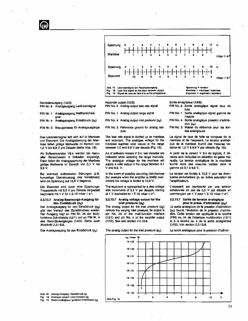
Recorderausgang (1212): PIN Nr. 5 Analogausgang Leckratensignal
PIN Nr. 1 Analogausgang MeBbereichssl-gnal
PIN Nr. 4 Analogausgang EinlaBdruck (Pe)
PIN Nr. 3 Bezugsmasse fOr Analogausgange
Das leckratensignal teilt sich auf In Mantissa und Exponent Die Analogspannung der Mantisse liefert' gOltige MeBwelte im Bereich von , ,0 V bis 9,9 V pro Dekad8 (siehe Abb. 18).
Ab Soflwareversion V3.4 werden bei manueller Bereichswahl 2 Dekaden angezeigt Dann liefert die Analogspannung der Mantissa gOltige MeBwerte im Bereich von 0,1 V bis 9,9V.
Bei eventuel! auftretenden Storungen (z.e. kurzzeitige Obersteuerung des Verstarkers) wird die Spannung auf 10,6 V begrenzt
Der Exponent wird durch eine Spannungs· Treppenstufe mit 0,5 V pro Dekade dargastellt beginnendmit1 Vfiir1 E-10mbar·I·$'"1.
2.2.13.7 Analog-$pannungs-Ausgang fur den ElnlaBdruck (Pe)
Der Analogausgang fOr den EinlaBdruck (Pe)
gibt den Verlauf des EinlaBdruckes wieder. Der Ausgang liegt an PIN Nr. 24 dar Multifunktions-Schnittstelle (1211) und an PIN Nr. 4 des Recorderausgangas (1212). Siehe auch Abschnitt 2.2.13.6.
Der Analogausgang fOr den EinlaBdruck (Pe)
Abb.19 Analog-Ausgang I elnlaBdruck Pe Flg. 19 Analogue output I inlel pressure Pe Fig. 19 Sortie analoglque I pression d'admlsslon PE
.
Spannung 0 2 3 4 5 • 7 8 • ,. V
MantiSse I I I I I " " I I
I I I I I I I I I I 2 3 4 , 8 7 8 • mbar·Hr
Spannung 0 , 3 4 , • 7 • • 10 V
Exponent ~-t-t-t-t-t-t-t-t-t-t-t-t-t-t-t-t-~-t-~-1
·10 .. .. -4
Abb. 18 Leckralenslgnal am Recorderausgang Flg. 18 Leak rate signal at the cllarl recorder output Fig. 18 Signal de !aux de fulta a la sorlie enreglstreur
Recorder output (1212): PIN No.5 Analog output leak rate signal
PIN No.1 Analog output range signal
PIN No.4 Analog output inlet pressure (Pe)
PIN No.3 Reference ground for analog out~ puts
The leak rate signal is dMded up as mantissa and exponent The analogue voltage for the mantissa supplies valid values in the range between 1.0 and 9.9 V per decade (Fig. 18).
As of software release V 3.4, two decades are indicated when selecting the range manually. The analogue VOltage for the mantissa will supply a valid outpUt in the range between 0.1 V and 9.9. V.
In the event of possibly occurring disturbances (for example when the amplifier is briefly overdriven) the voltage is limited to 10.6 V.
The exponent is represented by a step VOltage with increments of 0.5 V per decade, starting at 1 V equivalentto 1 E·10 mbar·I·,$'"'.
2.2.13.7 Analog voltage output for the Inlet pressure (PE)
The analog output for the inlet pressure (Pe)
reflects the varying inlet pressure. Its output Is pin No. 24 of the multi-function interface (1211) and pin No. 4 of the recorder output (1212). See also section 2.2.13.6.
The analog output for the Inlat pressure (PE)
Pe /mbar
1E+03
1E+02
1E+01
., 0 2 • • • mbar·I·s-1
Spannung = tension Mantissa = mantissa I mantissa Exponent = exponent I axposanl
Sortie enregi8treur (1212): PIN No.5 Sortie analogique signal taux de
fuito PIN No.1 Sortie analogique signal gamma de
mesure PIN No.4 Sortie analogique pression d'aclmis
sion (PE) PIN NO.3 Masse de reterence pour les sor-
ties analogiques
Le signal de taux de fuite sa compose de la mantissa et de I'exposant La tension analogique de la mantissa foumit des mesures va~ lables de 1,0 V a9,9 V par dilcade (fig. 18).
A partir de la version V 3.4 du logiciel, 2 decades sont indiquees en selection de game ma~ nueUe. La tension analogique de la mantissa foumit alors des mesures valides dans la gamme de 0,1 a 9,9 V.
La tension est Iimit8e a 10,6 V pour las even· tuelles perturbations (p. ex. brbve saturation de I'amplificateur).
L'9)!:p0s8nt est representS par une tension echelonn6e en pas de 0,5 V par decacte en commengant par 1 V pour 1 E-10 mbar·I·s-1.
2.2.13.7 Sol1le de tenston analoglque pour la press. d'admlBslon (pEl
La sortie ana/ogique de la pression d'aclmission (PE) foumit ,'evolution de /a pression d'aclmission. Catta tension est appliquee a la broche (PIN) no. 24 de I'interface multifonction (1211) at a la broche no. 4 de la sortie enregistreur (1212). Voir section 2.2.13.6.
La sortie analogique pour la pression d'aclmis-
./ V
-l-I-" 1e+00
1E-01 /. 1e-02 / 1e-03
1e-04
0 AbbJFlg.19
2 4 • • 10 V
31
-----------'----~ liefert sine Ausgangsspannung von 0 bis lOV. Dar Zusammenhang zwischen Spannung und Druck ist 8US Abb. 19 ersichtlich. Beispiel fOr Druck-Ausgabe: AnaJog-Ausgang "" ',0 V ergibt EinlaBdruck PE = ',0 '10.1 mbar
2.2.13.8 Kopfh6rer-AnschluB Neben dam seitlich an dar Bedien-Einheit" (11/1) eingabauten SchlCtsselschalter (11/2) befindet sich ein KopfhOrer-AnschluB (1113). Hier lassen sich Kopfhorer (Impedanz > 500 il) mit einem 3.5 mm Klinkenstecker anschlieBen.
2.2.13.9 Hal.kelte Die Bedieneinhelt laBt sich mit Hilte siner Halskette leieht am KOrper des UL 100 PLUS· Benutzers tragen. Zur 8efestigung ist dar KettenschlUssel fest in die SchloBbohrung (11/4) einzudrucken. Durch leichtes Verdrehan lam sich dar KettenschlOssel wieder aus dam SchloB herausziehen und die Katte entfemen.
2.2.13.10 Verblndung zwischen Bedleneln· helt und Lecksuchmodul
Die Spiralleitung zwischen Lecksuchmodul und Bedieneinheit laBt sich am Lecksuchmodul mittels einer im Leitungsbehalter vomandenen Steckvorrichtung trennen, um z. B. die 10m VeriAngerungsleitung (Kat-Nr. 165 43) einzusetzen. Dazu ist zunAchst die Spiralleitung vollstandig aus dem Leitungsbehalter und der BuchsentrAger samt Buchsa und Stecker bis zum EinrastBn vorsichtlg an der Leitung gagen den Federzug aus der Leitungsbox hersuszuziehen.
Jetzt kann der Stecker durch Anfassen an der Griffhulse aus der Buchse herausgezogen werden. Die Entriegelung der Steckvorrichtung geschieht dabei automatisch. Zum Stecken mussen die roten lagemarkierungen zueinander zeigen.' Mit eingestecktem Stecker kenn man die Steckvorrichtung wieder in der Kabelbox verschwinden lassen. Dazu ist vorsichtig an der Lettung zu ziehen und glaichzeitig dar Buchsentrager mittels leichler Drehung am Stecker im Uhrzeigersinn zu entriegeln und durch Nachgeben der Leitung in die Leitungsbox zurOckgleitan zu lassen.
Hlnwela Den Steckvarbinder hinter der RAndelmutter ergreifen. Durch Ergreifen und Drehen der RAndelmutter lOst sich der innere Teil und wird in den UL 100 PLUS zurOckgezogen.
32
supplies an output voltage ranging between 0 and 10 V. The relationship between voltage and pressure is given in Fig.19. Example of a pressure output Analog output ::. 1.0 V is equivalent to an inlet pressure PE = 1.0 ·10-' mbar
2.2.13.8 Headset Socket Next to the keylock switch (11/2) on the side of the remote control unit (11/1) is a headset socket (1113). Headsets (impedance >5000) can be connected with a 3.5 mm phone plug.
2.2.13.9 carrying Chain The carrying chain included with the accessories can be used to wear the remota control unit The carrying chain is attached by firmly pressing n into the lock (11/4). The carrying chain may be detached by Slightly tuming the end within the lock and removing it
2.2.13.10 Connection Cable between Remote Control Unit and Leak Oetaction Module
The coiled cord between leak detection module and remote control unit may be separated via the connector within the cable retainer, for eXample in order to extend the length using the 10 m long extension cable (Cat-No. 165 43). To do this. first carefully pull the coiled cord out of its retainer, including the springloaded socket holder with socket and plug. until the cable is arrested.
Now the plug can be detached from the socket by holding it at its outer casing. In doing so the plug is automatically released. For renewed plugging the two red markings must face each other. After the plug has been in· serted the entire connection is placed back in the cable retainer. To do this. carefully pull at the cable while slightly twisting the socket holder at the plug in the clockwise direction. By lightly releasing the cable it will then slide back into its retainer.
NOIe Grasp the connector behind the knurled collar. If the knurled collar is grasped and tumed. the intemal portion is disconnected and withdrawn into the UL 100 PLUS.
sion (PE) foumit une tension entre a et 10 V. La relation entre la tension et la pression est decrite par Fig. 19. Example d'une sortie de pression: sortie analogique ::. 1,0 V donne pression d'admission PE = 1,0.10.1 mbar
2.2.13.8 Raccordement pour casque d'Bcoute
A cOt8 du commutateur a cia (11/2) situa sur Ie cOte de "unite de commande ('111), on trouve un raccordement pour casque d'ecoute (1113) (impedance > 500 0) equipe d'une fiche Ii jack (3.5 mm).
2.2.13.9 Chaine de suspension Elle permet a I'utilisateur de UL , 00 PLUS de porter aisement I'unite de commande. La chaine se fixe en enfonant la cia fortement dans Ie verrou (1114). Pour retirer /a chaine. enlever la cia en la toumant legerement
2.2.13.10 Cable de connexlon entre l'unlt8 de commande at Ie module detecteur
Oe cable spirala entre Ie module detecteur at J'unite de commande paut Atre separe du connecteur situs dans Ie bo1ter de cable du module dstectBur pour utiliser p.ex. une rallonge de 10 m (ref. 165 43). Retirer d'a'bord Ie cable spirala completement at prudemment de son baitier et Ie support douitle a rassort avec la douille et la fiche jusqu'a l'enclenchement
On paut rnaintenant retirer la fiche de la aouille en la saisissant par son corps exteme. La liberation du connecteur a fiche sa fait automatiquement Pour ficher a nouveau, mettre les marques rouges face a face. Lorsque la fiche est inser8e on paut remettre Ie connecteur dans Ie bomer du cable en tirant prudemment sur Ie eBble et deverrouiltant simultanament Ie support douitle en toumant legerement la fiche dans Ie sans des aiguilles d'une mantra. En IAchant Ie cable, iI glissa dans son bomer.
Remarque Saisir Ie connecteur derriere I'ecrou molate. n faut Ie safsir et Ie toumer pour degager la partie interne qui est tire dans UL 100 PLUS.
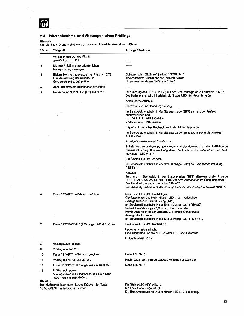
~-------------------------2.3 Inbetriebnahme und Abpumpen eines Priiflings
Hlnwels Die Lfd. Nr. 1, 3 und 4 sind nur bel der ersten Inbetriebnahme durchzufOhren,
Lfd.Nr. .T3tigkeit
Aufstellen des UL 100 PLUS gemaB Abschnitt 2.1
2 UL 100 PLUS mit der erforderlichen Netzspannung versorgen
3
4
5
6
7
Elektronikeinheit ausklappen (5. Abschnitt 2.7) Grundeinsteltung der Schalter im Servicefeld (Abb. 25) prufen
Ansaugstutzen mit Blindflansch schlieBen
Netzschalter "ErN/AUS". (8/7) auf "ErN"
Taste "START" (4/24) kurz drucken
Taste "STOPNENT" (4/2) lange (>25) drOcken.
a Ansaugslutzen Offnen.
9
10
11
12
PrOfting anschlieaen.
Taste "START" (4/24) kurz drOcken.
PrOfJing mit Helium besprOhen.
Taste "STOPNENT" langer als 2 5 drQcken.
'3 PrOfling abkoppeln.
Hinwels
Ansaugstutzen mit Blindflansch schlieBen oder neuen PrOfJing anschliel3en.
Der MeBbetrieb kann durch kurzes CrOcken der Taste "STOPNENT" unterbrochen werden.
Anzeige I Reaktion
Schlitzschalter (26/2) auf Stellung "NORMAL" Bedienschalter (26113) aile auf Stellung "Auto" Umschalter fUr Masse (26/11) auf "M4"
Initialisierung des UL laO PLUS; auf der Statusanzeige (26/1) erscheint "INIT" Die Bedienelnheit wird initialisiert; die Status-LED (4/1) leuchtel grOn.
Anlauf der Vorpumpe.
Elektronik wird mit Spannung versorgt.
1m Servicefel~ erscheint in der Statusanzeiga (26/1) alnma! durchlaufend nachstehender Text UL 100 PLUS VERSION-3.0 DATE-xx.xx.xx TIME-xx.xx.xx
Beginn automatischer Hochlauf der Turbo-MoJekularpumpe.
1m Servicefeld erscheint in der Statusanzeige (26/1) alternierend die Anzeige AGGL/VAG.
Anzeige Vorvakuum-und Einlal3druck.
Sobald Vorvakuumdruck Pv SO,l mbar und die Nenndrehzahl der TMP-Pumpe erreicht ist, erfolgt Bereitmeldung durch Aufleuchten der Exponenten und NullIndikatoren lED (4/21)
Die Status-LED (4/1) erJischt.
1m Servicefeld erscheint in der Statusanzeige (2611) die Bereitschaftsmeldung " STBY".
Hlnwels Erscheint im Servicefeld in der Statusanzeige (26/1) aiternierend die Anzeige ACCll SNIF, war der Ul 100 PLUS vor dem Ausschalten im Schnuffelbetrieb. Der EinlaB wird evakuiert; Anzeige "EVAC" Der Stand-By Betrieb wird Obersprungen und auf der Anzeige erscheint "SNIF".
Die Status-LEO (4/1) leuchtet grun. Die Exponenten und Null-lndikalor LED (4/21) vertOschen. Anzeige fallender EinlaBdruck Pe (4/23). 1m Servicefeld erscheint in der Statusanzeige (26/1) "EVAC" Sobald Einlal3druck Pe S 0,2 mbar, Umschalten der Kombi-Anzeige (413) auf Leckrate. Ein kurzes Signal ertOnt. Anzeige der Leckrate. 1m Servicefeld erscheint in der Statusanzeige (26/1) "MEAS".
Die Status-lED (4/1) leuchtel rot.
leckratenanzeige erlischt. Die Exponenten und die NulHndikator LED (4/21) leuchten.
Flutventil Offnet Mrbar.
Slehe Lfd. Nr. 6
Nach Ablauf der Ansprechzeit ggf. Anzeige der Leckrate.
Siehe Lfd. Nr. 7
Die Status"lED (4/1) erlischt. Die leckratenanzeige erlischt Die Exponenten und die NulHndikator LED (4/21) leuchtel'!'
33
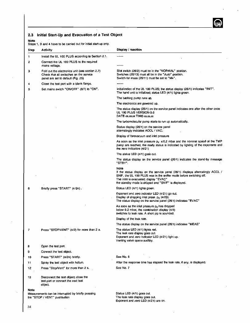
--------------__ --_________ mm 2.3 Initial Start-Up and Evacuation 01 a Test Object
Note Steps 1, 3 and 4 have to be carried out for initial start-up only.
Step
2
3
• 5
6
7
Adivity
Install the UL 100 PLUS according to Section 2.1.
Connect the UL 100 PLUS to the required mains voltage.
Fold out the electronics unit (see section 2.7) Check that all swilsches on the service panel 'are set to default (Fig. 25)
Close the test port with a blank flange .
Set mains switch "ON/OFF" (817) to "ON".
Briefly press "START" (4/24).
Press "STOPNENT" (4/2) for more than 2 s.
a Open the test port.
9
'0
" '2
Connect the test object.
Press "START" (4/24) briefly.
Spray the test object with helium.
Press "StopNent" for more than 2 s.
, 3 Disconnect the test object; close the test port or connect the next test objecl
Note Measurements can be interrupted by briefly pressing the "STOP 1 VENr pushbutton
34
Display I reaction
Slot switch (26/2) must be in the "NORMAL" position. Switches (26/13) must all be in the "Auto" position. Switch for mass (26111) must be set to "M4" .
Initialization of the UllOa PLUS; the status display (26/1) indicates "INIT". The hand unit is initialized; status lED (4/1) lights green.
The backing pump runs up,
The electronics are powered up.
The status display (26/1) on the service panel indicates one after the other once UL , 00 PLUS VERSION·3.0 DATE·xx.xx.xx TIME·xx.xx.xx
The turbomolecufar pump starts to run- up automatically.
Status display (26/1) on the service panel alternatingly indicates ACel I VAC.
Display of forevacuum and inlet pressure
As soon as the inlet pressure Pv :S 0,2 mbar and the nominal speed of the TMP pump are reached, the ready status is indicated by lighting of the exponents and the zero indicators (4/21)
The status lED (4/1) goes out
The status display on the service panel (26/1) indicates the stand-by message oSTBY". .
Note If the status display on the service panel (26/1) displays alternatingly ACel 1 SNIF, the UL 100 PLUS was in the sniffer mode before switching 'off. The inlet is evacuated; display" EVAC" the standby mode is skipped and "SNIF" is displayed.
Status lED (4/1) lights green.
Exponent and zero indicator lED (4/21) go out. Display of dropping inlet press. PE (4/23). The status display on the service panel (26/1) indicates "EVAC"
As soon as the inlet pressure PE has dropped below 0.2 mbar, the combination display (4/3) switches to leak rate. A short pip -is sounded.
Display of the leak rate.
The status display on the service panel (26/1) indicates "MEAS"
The status LED (4/1) lights red. The leak rate display goes out Exponent and zero indicator LED (4/21) light up. Venting valve opens audibly.
See No.6
After the response time has elapsed the leak rate, if any, is displayed.
See No.7
Status lED (411) goes out The leak rate display goes out Exponent and zero LED (4/21) are on.
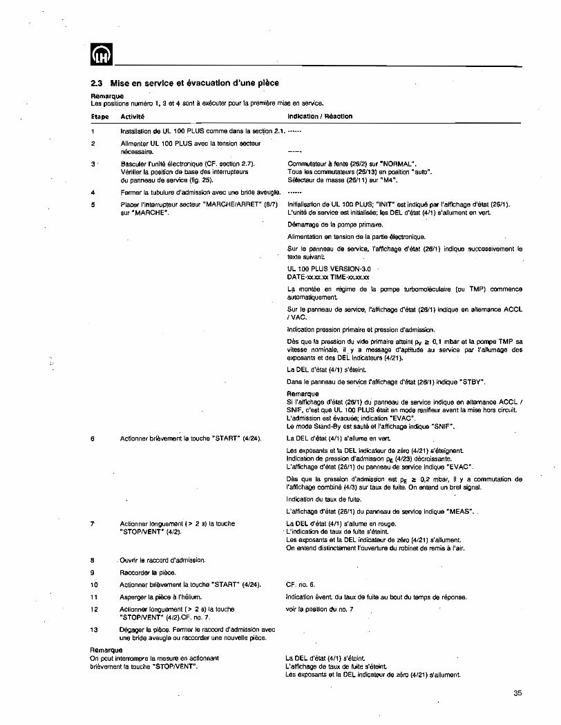
~-------------------------2.3 Mise en service et evacuation d'une piece
Remarque Les positions numaro " 3 at 4 sont ell executer pour la premiere mise en service.
Etape Activite Indication I Reaction
Installation de Ul 100 PLUS comma dans 1a section 2.1 .••••••
2 Alimenter UL , 00 PLUS avec la tension secteur necessaire.
3 Basculsr I'unite electronique (CF. section 2.7). Verifier la position de base des interrupteurs du panneau de service (fig. 25).
4 Fermer 18 tubulure d'admission avec une bride aveugle.
5
6
Pla,cer I'interrupteur secteur "MARCHE/ARAET" (817) sur n MARCHED.
Actionner brievement la touche "START" (4/24).
Actionner longuement (> 2 5) la touche "STOPNENT" (4/2).
8 Ouvrir Ie raccord d'admission.
9
10
11
12
Raccorder la piece.
Actionner briEwement la touche "START" (4/24).
Asperger la piece a 1'h9lium.
Actionner longuement (> 2 s) la touche "STOPNENT" (4/2}.CF. no. 7.
13 Degager la piece. Fermer Ie raccord d'admission avec une bride aveugls ou raccordsr une nouvelle piece.
Remarque On peut interrompre la mesure en actionnant brievement la touche "STOPNENT".
Commutateur a fente (26/2) sur "NORMAL". Tous les commutateurs (26/13) en position "auto". Selecteur de masse (26/11) sur "M4".
Initialisation de UL 100 PLUS; "INIT" est indique par I'affichage d'etat (2611). L'unile de service est initialisee; les DEL d'etat (411) s'allument en vert.
Demarrage de 18 pompa primaire.
Alimentation en tension de la partie electronique.
Sur Ie panneau de service, I'affichage d'etat (26/1) indique successivement Ie texte suivant:
UL 100 PLUS VERSION·3.0 DATE·xx.xx.xx TIME·xx.xx.xx
L{l montee en regime de 18 pompa turbomoleculaire (au TMP) commence automatiquement
Sur Ie panneau de service, I'affichage d'etat (26/1) indique en alternance ACCL IVAC.
Indication pression primaire et pression d'admission.
Des que la pression du vide primaire atteint Pv ~ 0,1 mbar et la pompe TMP sa vitesse nomina/e, il. y a mess,age d'aptitude au service par I'allumage des exposants et des DEL indicateurs (4/21).
La DEL d'etat (4/1) s'eteint
Dans Ie panneau de serv!ce I'affichage d'etat (26/1) indique "STBY".
Remarque Si I'affichage d'etat (26/1) du panneau de service indique en alternance ACCL 1 SNIF, c'est que UL 100 PLUS etait en mode renifleur avant la mise hors circuit. L'admission est evacuee; indication "EVAC". La mode Stand-By est saute at I'affichage indique "SNIF".
La DEL d'etat (4/1) s'allume en vert.
Les exposants et la DEL indicateur de zero (4/21) s'eteignant Indication de pression d'admission Pe (4/23) decroissante. L'affichage d'etat (26/1) du panneau de service indique "EVAC".
Des que la pression d'admission est PE ~ 0,2 mbar, iI y a commutation de I'affichage combine (4/3) sur taux de fuite. On entend un bref signal.
Indication du taux de fuite.
L'affichage d'etat (2611) du panneau de service indique "MEAS" ..
La DEL d'etat (4/1) s'allume en rouge. . L'indication de taux de fuite s'ereint. Les exposants et la DEL indicaleur de zero (4/21) s'allument. On entend distinctement I'ouverture du robinet de remis a I'air.
CF. no. 6.
Indication event du taux de fuile au bout du temps de n§ponse.
voir la position du no. 7
La DEL d'etat (4/1) s'eteint L'affichage de taux de fuite s'eteint Les exposants et la DEL indicateur de zero (4/21) s'allumant.
35
--~----------------------~ 2.3.1 Einstellen der Uhrzeit und Datum Urn bel Ausgaben des UL 100 PLUS spezla!! uber die V.24/RS 232 C-Schnittstelle gOll198 Werts fOr Vhrzeit und Datum zu erhalten, mussen diese gegebenenfalls neu eingestellt werden. Die Kontrolle dar 1m Gerat programmierten Uhrzeit und Datum kann auf zwei Arten erfolgen:
• nach dam Netzeinschalten lauft auf der aIphanumerischen Anzeige (2611) eine Initiali· sierungsanzeige ab, in der auch Uhrzeit und Datum angezeigt werden (Abschnitt 2.3.1).
• im SERVICE-Betrieb (slaha Abschnitt 2.7 Service-F unktionen).
Die Einstellung von Uhrzeit und Datum karin ebenfaUs auf zwei f\rten dur.chgeffihrt werden:
• am Gerat Ober die Bedieneinheit 1m SERVICE-Setrieb. Dies ist beschrieben im Abschnitt 2.7 im Ablaut nach Betlltigung der T_"HANO".
- Dber die V.24/RS 232 C-SchnittsteUe. Siehe hierzu S8 10.207.
36
2.3.1 Entering time and date In order to obtain valid outputs for date and time from the UL 100 PLUS via the V.24/RS 232 C interface date and time have possible to be reentered. Date and time programmed into the UL 400 can be checked as follows:
- after switching on the mains, initialization values are indicated on the alphanumerical display (26/1). These include time and date (see Section 2.3.1).
- in the servipe mode (see Section 2.7 Ser-vice functions).
Time and date may also be entered in two ways:
- on the unit itself via the hand unit in the service mode. This i,s described in Section 2.7 in the sequence after operating the "Manual" pushbutton.
- through the V.241RS 232 C interface. Refer to S8 10.207.
2.3.1 Introduction de I'heure et de la date II faut eventuellement introduire a nouveau la date at I'heure pour que ces valeurs soient correctes lars des sorties de UL 100 PLUS, notamment par I'interface V.24/RS 232 C~ Le contrOle de la date et de I'heure programmees dans I'apparell sa fait de deux manleres difMrentes:
- apras la mise en circuit, I'affichage alphanumerique (2611) mantra une initialisation indiquant egalement la date at I'heure (CF. section 2.3.1).
- en mode SERVICE (CF. section 2.7 fonctions de service)
l'introduction de' la date et de I'heure se fait egalement de deux manieres differentes:
- sur l'appareil, par I'unite de commande en mode SERVICE. Vous en trouverez la description dans la section 2.7, dans la sequence apres I'actionnement de la touche "manuelle".
- par I'interface V.24/RS 232 C. Consulter pour eela S8 10.207 •.
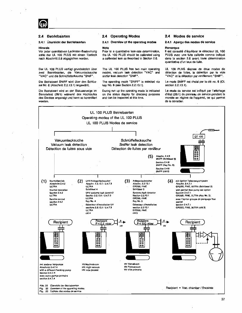
mm ________________________ __ 2.4 Betrlebsarten
2.4.1 Uberslcht dar Betrlebsarten
Hlnwels Vcr jader quantitativen Leckraten~Bestimmung sollte der UllOa PLUS mit a'inam Testleck nach Abschnitt 2.6 abgeglichen werden.
Der UL '00 PLUS verlOgt grundsatzlich Ober zwei Betriebsarten, die Vakuumlecksuche "VAC" und die SchnOffellecksuche "SNIF".
Die Betriebsart SNIFF wire! Ober den SchlUssel Nr. 6 (Abschnitl 2.2.13.1) angewahlt
Die Betriebsart wird an der Statusanzeige im Sef',(icefeld (26/1) wah rend des Hochlaufes des Gerates angezeigt und kann so kontrofliert werden.
2.4 Operating Modes
2.4.1 Overview 01 the operating modes
Note Prior to a quantitative leak-rate determination, the Ul '00 PLUS should be calibrated using a calibrated leak as described in Section 2.6.
The UL 100 PLUS has two main operating modes, vacuum leak detection "VACn and sniffer leak detection nSNIF1t.
The operating mode "SNIFF" is selected via key No.6 (see Section 2.2.13.1).
During run up the operating mode is indicated on the status display for checking purposes and can be inspected at this time.
UL 100 PLUS Betriebsarten
Operating modes of the UL 100 PLUS
UL 100 PLUS Modes de service
Vakuumlecksuche Vacuum leak detection
Detection de fuites sous vide
Schnuffellecksuche Sniffer leak detection
Detection de fuites par renifleur
2.4 Modes de service
2.4.1 Aperyu des modes de service
Remarque II est conseille d'equilibrer Ie detecteur UL 100 PLUS avec une fuits calibree comme indique dans la section 2.6 avant toute determination quantitative d'un taux de fuite.
UL 100 PLUS dispose de deux modes de detection de fuites, la detection par Ie vide "VAC" et ia detection par reniflement "SNIF".
Le mode SN'IFF est choisi par la cle no. 6 (Cf. section 2.2.13.1).
Le mOOe de service est indique par r affichage d'etat (26/1) du panneau de service pendant la montee en regime de I'appareil, ce qui permet de Ie contrOler.
.r-~
...L...L.
(5) Abschn.2.4.8 SNIFF (SchIOssetS)
Section 2.4.8 SNIFF (Key No.6)
Section 2.4.8 SNIFF (clli 6)
(1) Normalbetrleb (2) UHV·Anlagenlecksucher (3) Anlagenlecksucher Abschnlll 2.4.2 Abschn.2.2.13.112.4.7.3 Abschn.2.2.13.1 ULTRA ULTRA GROSS, FINE
Normal operation SchJUssel4 Sch[(lssel5
Section 2.4.2 UHV systems leak detecto'r Systemll leak detector ULTRA Section 2.2.13.112.4.7.3 Seclion 2.2.13.1
Service normal ULTRA GROSS, FINE
secllon 2.4.2 Key No.4 Key No.5
ULTRA oetecteur d'installation UV Detecteur d'installation lIections 2.2.13.1 '2.4.7.3 lIectlon 2.2.13.1 ULTRA GROSS, FINE ch!4 chi 5
( Rezipient ):14 p<~bar HV
mit anderer Vorpumpe Abschnitt 2.4.7.4 with a dille rent backing pump Section 2.4.7.4 avec autre pompe primaire section 2.4.7.4
Abb. 20 Obe.sicht der Belriebsarten
HV:Hochvakuum HV: High vacuum HV: vide pousse
Fig. 20 Overview 01 the operalJng modes Fig. 20 Tableau des mod8$ de service
W. Vorvakuum w: FOfQVaCUUm w: vide prlmalre
(4) mit Option Tellstrompumpsatz Abschn.2.4.7.1 GROSS, FINE, ULTRA (SchlOssel 3)
with partial flow pump set option SeclJon 2.4.7.1 GROSS, FINE, ULTRA (Key No.3)
avec I'optlon groupe de pompage lIul( par!!et sactlon 2.4.7.1 GROSS, FINE, ULTRA (cle 3)
( Rezipient ) II
Rezipient "" Vac, chamber l.Enceinte
37
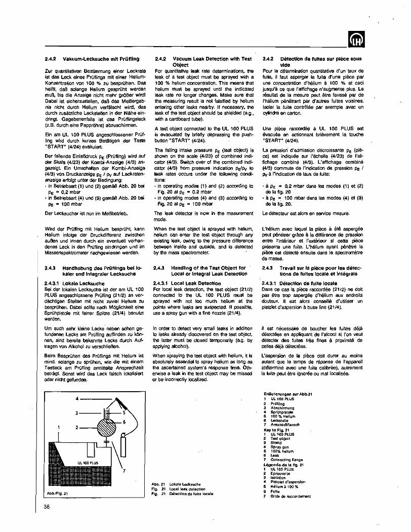
--------------------------~ 2.4.2 Vakuum·Lecksuche mit Priming
Zur quantitativen ,Bestimmung ainer Leckrate ist das Leek aines PrOflings mit ainer HeliumKonzentration von 100 % zu besprOhen. Das helBt, daB salange Helium gesprOht werden muB, bis die Anzeige nicht mehr groBer wirdl Dabei 1st sicherzustellen, daB das MeBergeb· nis nicht durch Helium verlAlscht wird. das dUTCh zusatzliche Leckstellen in der Nalls aindringt Gegebenenfalls 1st das PrOflingsleck (z.B. durch aine PapprOhre) abzuschirmen.
Ein am UL 100- PLUS angeschlossener PrOf· ling wird dUTCh kurzes Beta.tigen ,der Taste "START" (4/24) evakuiert.
Der faltende EinlaBdruck PE (PrOfling) wird auf der Skala (4/23) der Kombi-Anzeige (413) angezeigt Ein Umschatten dar Kombi-Anzeige (4/3) von Druckanzeige Pe l Pv auf Leckratenanzeige erfolgt unter der Bedingung: - in Betriebsart (1) und (2) gemaB Abb. 20 bei
PE "" 0,2 mbar - in Betriebsart (4) und (3) gemaB Abb. 20 bei
PE "" 100 mbar
Der Leeksucher ist nun im MeBbetrieb.
Wird der PrOfling mit Helium besprOht, kann Helium in10lge der Druckdifferenz zwischen auBen und innen durch ain eventuel! vorhandenas Leek in dan PnJfling eindringen und 1m Massenspaktrometar nachgewiesen werden.
2.4.3 Handhabung des Prii111ngs bello--kaler und integraler Lecksuche
2.4.3.1 Lokale _Lecksuche Bel der lokalen Lecksuche ist der am UL 100 PLUS angeschlossene PrOfling (21/2) an verdachtigen Stellen mit nicht zuviel Helium zu besprDhen. Dabei sollte nach MOglichkeit eine SprOhpistole mit feiner Spitze .(21/4) benutzt werden.
Um auch sehr kleine Lecks neben schon gefundenen Lecks am PrOfling auffinden zu kOnnen, sind bereits bekannte Leeks durch Auftragen von Alkohol zu verschlieBen.
Beim BesprOhen des PrOflings mit Helium ist mind. solange zu sprOhen, wie die mit elnem Testleck am PrOfling ermittelte Ansprechzeit betra-gt. Sonst wird das Leek falsch lokalisiert oder nicht gefunden.
Abb.lFlg. 21
38
2.4.2 Vacuum Leak Detection with Test Object
For quantitative leak rate determinations, the leak of a test object must be sprayed with a 100 % helium concentretio.n. This means that helium must be sprayed until the indicated leak rate no longer changes. Make sure that the measuring result is not falsified by helium entering other leaks nearby. If necessary, the leak of the test object should be shielded (e.g., with a cardboard tube).
A test object connected to the UL 100 PLUS is evacuated by briefly depressing the pushbutton "START" (4/24).
The falling intake pressure PE (test object) is shown on the scale (4/23) of combined indicator (413). Switch over 01 the combined indicator (413) from pressure indication PE/Pv to leak rates occurs under the following conditions: - in operating modes (1) and (2) according to
Fig. 20 at PE "" 0.2- mbar - in operating modes (4) and (3) according to
Fig. 20 at PE = laO mbar
The leak detector is now in the meaurement mode.
When the test object is sprayed with helium, helium can enter the test object through any existing leak, owing to the pressure difference between inside and outside, and is detected by the mass spectrometer.
2.4.3 Handling of the Test Object for Local or Integral Leak Detection
2.4.3.1 Local Leak Detection For local leak detection, the test object (21/2) connected to the UL 100 PLUS must be sprayed with not too much helium at the points where leaks are suspected. If possible, use a spray gun with a fine nozzle (21/4).
In order to detect very smail leaks in addition to leaks already discovered on the test object, the tatter must be closed temporarily (e.g. by applying alcohol).
When spraying the test object with helium, it is absolutely essential to spray helium as long as the ascertained system's response time. Otherwise a leak in the test object may be missed or be incorrectly localized.
Abb. 21 Lokale Lecksuche FIg. 21 Local leak detection Fig. 21 Oelectlon de fulle locale
2.4.2 Detection de fuHas sur piece sous vide
Pour la determination quantitative d'un taux de fuite, il faut asperger la fuite d'une piece par une concentration d'Mlium a 100 % et ceci jusqu'a. ce que I'affichage n'augmente plus. Le resultat de la mesure -paut etre 1aussB par de I'helium penetrant par d'autres fuites vOisines. lsoler la fuite contrOlee par exemple avec un cylindre en carton.
Una piece raccord~ a UL 100 PLUS est evacuee en actionnant brievement la touche "START" (4124).
La pression d'admission decroissante PE (piece) est indiquee sur l'echelle (4/23) de I'affichage combine (413). L'affichage combine (413) commute de I'indication de pression PE 1 Pv a I'indication de taux de fuite:
- it. PE = 0,2 mbar dans las modes (1) et (2) de la fig. 20
~ a PE = 100 mbar dans les modes (4) at (3) de la fig. 20.
La detecteur est slors en service mesure.
L'Mlium avec lequel la piece it. ete aspergee paut penetrer grace a la difference de pression entre l'in18rieur et I'exterieur si cette piece presents une fuite. L'helium ayant penetre la piece est detects ensuite dans Ie speetrometre de masse.
2.4.3 Travail sur 18 piece pour les detec-tions de 1ultes locale et integrale
2.4.3.1 Detection de tulte locale Dans ceo cas la piece raccordee (2112) ne doit pas !!itre trop aspergae d'helium aux endroits douteux. " est alors conseille d'utiliser un pistolet d'aspersion a buse fine (2114).
II est necessaire de boucher les fuites deja detectees en appliquant de I'alcool si I'on veut denecter des fuites tres fines a proximit9 de celles deja. detectees.
L'aspersion de la piece doit durer au mains autant que Ie temps de reponse de I'appareil (determine avec une fuite calibres), autrement la fuits peut Atre ignoree ou mal localisee.
Ertiuterungen zur Abb.21 1 UL 100 PLUS 2 Prllfllng 3 Abschlrmung 4 Spruhpistole 5 100 % Helium 6 Leckslelle 7 Anschlu8flansch Key to FIg. 21 1 UL 100 PLUS 2 Tesl object 3 Shield 4 Spray gun 5 100% helium 8 Leak 7 Connecting flange LCgende de la fig. 21 1 UL 100 PLUS 2 EprouveUe 3 lsolallon 4 PIstolel d'3Sperslon 5 Heliumal00% 8 Fulta 7 BrIde de raccordemenl
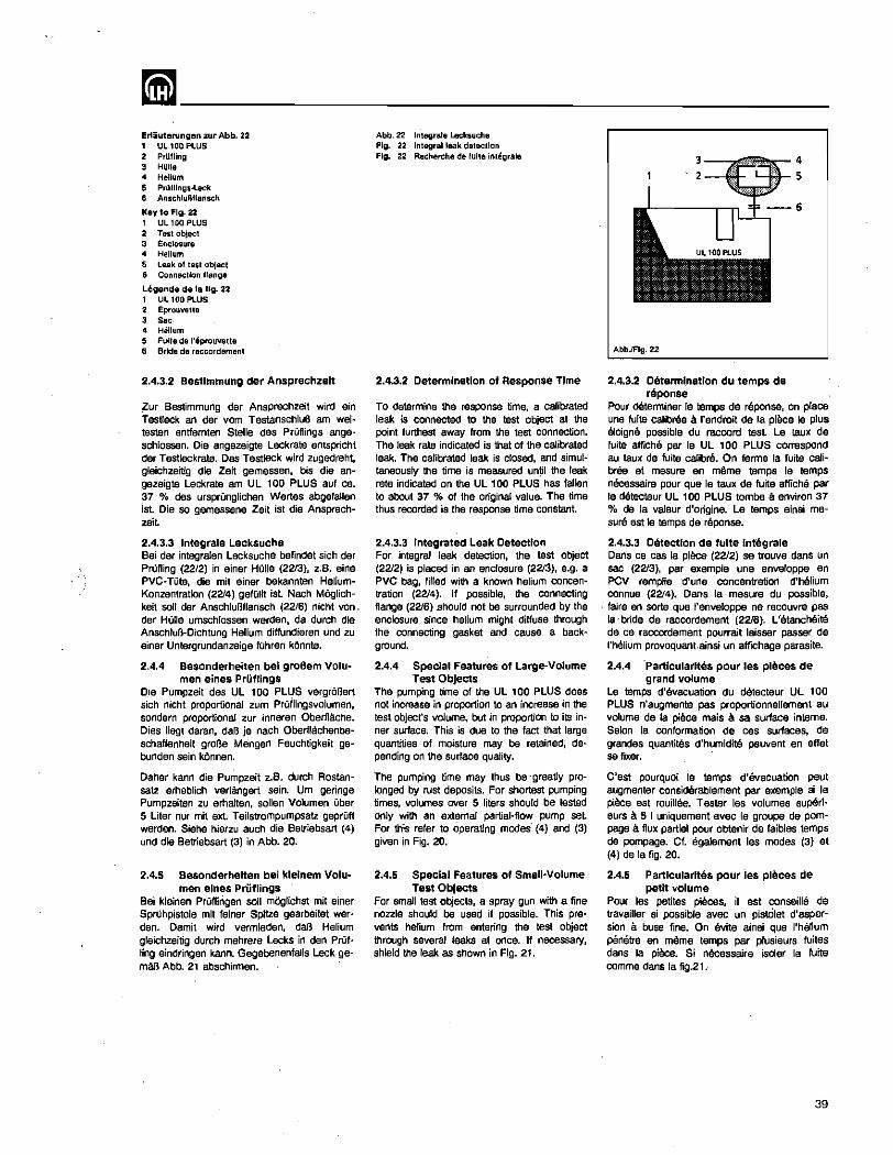
~-------------------------Erliuterungen zur Abb. 22 , UL 100 PLUS 2 Prllll1ng 3 HUlle
" Helium 5 Prllfllngs·Leck 6 AnsctlluBllansch
Key to fig. 22 1 UL 100 PLUS 2 Test object 3 Enclosure
" Helium 5 Leak 01 t8s1 object 6 Connection flange
Legende de Ie fig. 22 1 UL 100 PLUS 2 Eprollvelle 3 Sac " Helium 5 Fuite de l'eprQuvette 6 Bride de raccordemenl
2.4.3.2 Bestlmmung der Ansprechzeit
~ur Bestimmung der Ansprechzeit wird ein Testlack an der vom TestanschluB am wei~ testen entfemten Stelle des PrOflings angeschlossen. Die angezeigte Leckrate entspricht der Testleckrate. Cas Testleck wird zugedreht, gleichzeitig die Zeit gemessen, bis die angezeigte Leckrate am UL 100 PLUS auf ca. 37 % des ursprunglichen Wertes abgefaUen ist. Die so gemessene Zeit ist die Ansprechzeit.
2.4.3.3 Integrale Lecksuche Bei der integraJen Lecksuche befindet 5ich der PrOfling (22/2) in einer HOlle (2213), z.B. eine PVC-TUte, die mit einer bekannten HeliumKonzentration (2214) gefOlit jst Nach M6glichkeit soli der Anschlul3f1ansch (22/6) nicht von. der HOlle um5chlassen werden. da durch die AnschluB-Dichtung Helium diftundieren und zu einer Untergrundanzeige IOhren kOnnte.
2.4.4 Besonderheiten bel groBem Volu-men eines PrOflings
Ole Pumpzeit des UL 100 PLUS vergr613ert sich nicht proportional zum PrOflingsvolumen, sondern proportional zur inneren Oberilache. Dies liegt daran, dal3 je nach Oberflachenbeschaffenheit groBe Mengen Feuchtigkeit gebunden sein kannen.
Daher kann die Pumpzeit z.B. durch Rostansatz erheblich verlangert sein. Um geringe Pumpzeiten zu erhalten, sollen Volumen Ober 5 Liter nur mit ext. Teilstrompumpsatz geprOft werden. 5iehe hierzu auch die Belriebsart (4) und die Betriebsart (3) in Abb. 20.
2.4.5 Besonderheiten bei klelnem Volu-men eines PrOflings
Bei kleinen PrOflingen solt mOglichst mit einer SprOhpistole mit feiner Spitze gearbeitet werden. Damit wird vermieden, daB Helium gleichzeitig durch mehrere Leeks in den PrOfling eindringen kann. Gegebenenfalls Leek gemaB Abb. 21 abschirmen.
Abb.22 Integrale Lecksuche Fig. 22 Integral leak detection Fig. 22 Recherche de fulte integrale
2.4.3.2 Determination ot Response Time
To determine the response time, a calibrated leak is connected to the test object at the point furthest away from the test connection. The leak rate indicated is that of the calibrated leak. The calibrated leak is closed, and simultaneously the time is measured until the leak rate indicated on the UL 100 PLUS has fallen to about 37 % of the original value. The time thus recorded is the response time constant.
2.4.3.3 Integrated Leak Detection For integral leak detection, the test object (22/2) is placed in an enclosure (22/3), e.g. a PVC bag, filled with a known helium concentration (22/4). If possible, the connecting flange (2216) .should not be surrounded by the enclosure since helium might diffuse through the connecting gasket and cause a background.
2.4.4 Special Features ot Large-Volume Test Objects
The pumping time of the UL 100 PLUS does not increase in proportion to an increase in the test object's volume, but in proportion to its inner surface. This is due to the fact that large quantities of moisture may be retained, depending on the surface quality.
The pumping time may thus be -greatly prolonged by rust deposits. For shortest pumping times, volumes over 5 liters should be tested only with an external partial-flow pump set For this refer to operating modes' (4) and (3) given in Fig. 20.
2.4.5 Special Features ot Small·Volume Test Objects
For small test objeets, a spray gun with a fine nozzle should be used if possible. This pre· vents helium from entering the test object through several leaks at once. If necessary, shield the leak as shown in Fig. 21.
AbbJFig.22
2.4.3.2 Determination du temps de reponse
Pour determiner Ie temps de n§ponse, on place une fuita calibree a I'endroit de la piece Ie plus etoigna possible du raccord test Le taux de fuite afficM par Ie Ul 100 PLUS correspond au taux de fuite calibre. On ferme la fuite calibrae at mesure en mArne temps Ie temps necessaire pour que Ie taux de fuite affichs par Ie detecteur UL 100 PLUS tombe a environ 37 % de la valeur d'origioe. Le temps ainsi mesure est Ie temps de reponse.
2.4.3.3 Detection de tulte Integrale Dans ce cas la piece (22/2) sa trouve dans un sac (2213), par exemple une enveloppe en PCV remplie d'une concentration d'Mtium connue (2214). Dans la mesure du possible, fajre en sorte que I'enveloppe ne recouvre pas la -bride de raccordement (2216). L'etancheitS de ce raccordement pourrait laisser passer de I'helium provaquant.ainsi un affichage parasite.
2.4.4 ·Particularltes pour les phl!ces de grand volume
Le temps d'evacuation du detecteur Ul 100 PLUS n'augmente pas proportionnellement au volume- de la piece mais a sa surface interne. Selon la conformation de ces surfaces, de grandes quantites d'humidite peuvent en eftet se fIXer.
C'est pourquoi Ie temps d'evacuation peut augmenler considerablement par exemple si la piece est rouillee. Tester les volumes super;eurs a 5 I uniquement avec Ie groupe de pom· page a flux partiel pour obtenir de faibles temps de pompage. Cf. egalement les modes (3) et (4) de 10 fig. 20.
2.4.5 Partlcularltes pour les phl!ces de petit volume
Pour les petites pieces, il est conseille de travailler si possible avec un pistciret d'aspersian a buse fine. On Svite ainsi que 1'helium penetre en meme temps par plusieurs fuites dans la piece. Si necessaire isoler la fune comme dans la fig.21.
39
--------------------------~ 2.4.6 Besonderhelten bel klelnen und
graBen Leckraten
2.4.6.1 Kleine Leckraten Der UL 100 PLUS ist in der Lage, Leckraten bis 2'10.10 nibar-I·s·l nachzuweisen. Urn eine Anzeige in diesem Bereich ablesen zu kannen, ist 8ine eventual! vorhandene Untergrundanzeige mit Hilfe der Nullpunkttaste zu unterdrUcken.
Eins hOhere MeBwertaufiOsung erreicht man durch AnschlieBen aines Schreibers (Abschnitt 2.2.13.6) oder durch Ausgabe der Leckrate aber eine V.24-SchnitlStelle.
2.4.6.2 GroBe Leckraten Bei der Messung von greBen leckraten besteht die Gefahr der Verseuchung des Proflings und des UL 100 PLUS. ~aher die MaBzeit so kul'2 wie mOglich halten. Eins Verseuchung des PrOflings auBert sioh durch einen Untergrund, der auf der Kombi-Anzeige (413) abgelesen und gg1. mit der Nullpunkt-Taste (4/14) unterdrOckt wardan kann (siaha auch Abschnitt 2.2.6).
Hlnwels Durch Offnen der Gasballasteinrichtung (9/3) fUr mehrere Minuten kann eine Verseuchung der Vorvakuumpumpe behoben werden.
Eine Lokalisierung ist bei graBen Leekraten schwierig, da das Leek Helium schon aus ei· ner gewissen Entfernung ansaugl Daher nur wenig Helium mit einer Feinspruhspitze spruhen. Die quantitative Messung ist nur durch· fDhrbar, wenn 100 % Helium vor das Leek gebracht werden kann.
Haufige Leckratenmessungen uber Werte van 10.3 mbar+s·1 sollten mOglichst mit Teil· strompumpsatz durchgefuhrt werden. Siehe hierzu die Betriebsart (4) in Abb. 20.
Eine kurzzeitige Messung von Leckraten bis 10.2 mbar+s·1 ist jedoch auch ohne Teilstrompumpsatz mOglich.
2.4.7 8esondere Lecksuchabliiu1e
Die im Folgenden beschriebenen Lecksuchablaufe sind mit dam Lecksuchmodul des UL 100 PLUS in Verbindung mit jeweils notwendigen Zusatzgeraten mOglich. Sie erfordern im allgemeinen die Benutzung eines SchlQssels, mit dam die entsprechenden Ablaufe aktiviert werden.
2.4.7.1 Option Tel1strompumpsatz TPS UL 100 PLUS
Bei der Lecksuche mit einer Teilstrompumpe wird eine groBe Pumpe parallel zum LeeksuchereinlaB betrieben. Diese kann groBe Gasmengen abpumpen und entlastet damit den Lecksucher bzw. verschiebt seinen MeBbereich zu grOBeren Leckraten.
Die Lecksuche mit Teilstrempumpe ist dann ratsam, wenn entweder: - groBe Volumina schnell abzupumpen sind
- aine kurze Ansprechzeit an greBe Volumina gewQnscht wird
- bei hohen DrOcken (bis 100 mbar) Lecks gesucht werden sollen
40
2.4.6 Special Features at Low and High Leak Rates
2.4.6.1 Low Leak Rates The UL 100 PLUS is able to detect leak rates down to 2'10.10 mbar+s·1• To be able to read an indication in this range, any background has to be suppressed with the auto zero pushbutton.
Resolution may be increased by connecting a chart recorder (Section 2.2.13.6) or by outputting the leak rate through the V.24 interface.
2.4.6.2 High Leak Rates When measuring high leak rates, there is, a danger of the test object and UL 100 PLUS becoming contaminated. The measuring time should therefore be kept as short as possible. A contamination of the'test object makes itself felt through a background reading which may be read off on the combination display (4/3) and which may be suppressed by operating autozero pushbutton (4/14), if required (see also Section 2.2.6).
Note Contamination of the backing pump can be eliminated by opening the gas ballast valve (9/3) for several minutes.
With high leak. rates, it is difficult to localize a leak because the leak sucks in helium from quite a distance. It is therefore necessary to spray only a little helium with a fine nozzle. A quantitative measurement is only possible if 100% helium is brought in front of the leak.
Frequent leak rate measurements over values of 10-3 mbar+S"1 should best be carried out with a partial-flow pump set For this see operating mode (4) given in Fig. 20.
However, brief measurement of leak rates up to 10.2 mbar·I·S"1 is possible without the partial·flow pump set
2.4.7 Special Leak Detection Proce-dures
The leak detection processes described below can be carried out with thE;! leak de'taction module in connection with the stated additional components. Generally these leak detection processes require the use of a key to activate the corresponding functions.
2.4.7.1 Optional Partial·Flow Pump Set TPS UL 100 PLUS
For leak detection in connection with a partial· flow pump set. a large pump is connected in parallel to the inlet of the leak detector. It can pump out large quantities of gas, thereby relieving the leak detector of this duty and also expanding its measurement range.
Leak detection with a partial flow pump is recommended when either: - large volumes have to be pumped out quiCk
ly - a short response time is required in the case
of large volumes - detecting leaks at high pressures .(up to 100
mbar)
2.4.6 Panlcullrites pour les taux de 1ufte mlnlmes et lmportants
2.4.6.1 Petits taux de fuite UL 100 PLUS peut detecter des fuites jusqu's 2'10.10 mbar+s·1• Pour obtenir cetta preciSion, il faut interdire une eventuelle indication parasite avec la touche de remise s zero.
Une plus forte resolution des mesuras s'obtient ~n raccordant un enregistreur (sec. 2.2.13.6) au par la sortie des,',taux de fuite par une interface V.24.
2.4.6.2 Importants taux de fulte La mesure de grands taux de fuite presente Ie risque d'une contamination de la piece at du detecteur UL 100 PLUS. Le temps de mesure doit eire donc aussi court que possible. La contamination de la piece se manifeste par un fond parasite qui paut eire lu sur I'affichage combine (4/3) at supprime Ie cas echBant avec la touch. ZERO (4/14) (CF. section 2.2.6).
Remarque La pompe a. vide primaire peut etre decontaminae en ouvrant Ie dispositif de lest d'air (9/3) pendant quelques minutes.
Une localisation des tuites' importantas est difficile car elias attirent I'helium d'assez lain. II faut donc une buse fine pour n'asperger que peu d'heUum. La mesure quantitative ne paut etre executee que si "on paut obtenir de i'helium a. 1 00 % sur la fuite.
Utiliser de preference un groupe de pompage a flux partiel pour les fr8Quentes detections au· dessus de 10.3 mbar+s·1. Cf. mode de service (4) de la fig. 20.
Une breve mesure de taux de fuite jusqu's 10.2 mbar+s·1 est cependant possible sans ce groupe de pompage.
2.4.7 Procedures speciales de detection
Las procedures de detection decrites par la suite sont possibles avec Ie module detecteur de UL 100 PLUS assacie s differents appareils supplementaires. Ces procedures necessitent en general I'utilisation d'une cle pour activer les procedes.
2.4.7.1 Option groupe de pompage de flux partlel TPS UL 100 PLUS
Pour 18 detection des tuites avec une pompe a. flux partiel, on fait Iravailler une grosse pompa parallelement s I'admission du detecteur. Elle permet de pomper de grandes quantites de gaz et soulage ainai Ie de~ur au decare sa gamme de mesure vers les taux de fuite plus for:ts. La detection avec pompa a flux partielle est conseillee dans las cas suivants: - de grands volumes doivent etre evacues
rapidement - un temps de reponse rapide est necessaire
pour de grands volumes - pour las fortes pressions Uusqu's 100 mbar)
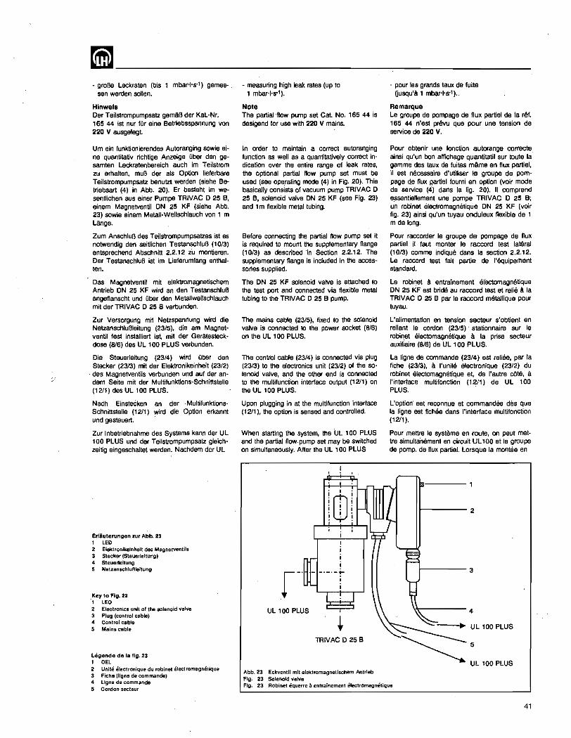
mm ________________ ~--------* graBe Leckraten (bis 1 mbar·'·s·1) games·
sen werden sollen.
Hlnwels Der Teilstrompumpsatz gemAB der Kat.-Nf. '65 44 ist nur fOr aine Betriebsspannung von 220 V ausgelegt.
Urn ein funktionierendes Autoranging sowie aine quantitativ richtige Anzeige Ober den g9-samten Leckratenbereich 8uch im Teilstrom zu arhatten, muB der als Option Heferbare Teilstrompumpsatz benutzt werden (siehe Betriebsart (4) in Abb. 20). Er besteht im wesentlichen aus ainer Pumpa TRIVAC 0 25 Bt
einem Magnetventil ON 25 KF (siehe Abb. 23) sowie einem MetaU-Wellschlauch von 1 m Lange.
Zum AnschluB des Teils'trompumpsatzes ist as notwendig den seitlichen TestanschluB (10/3) entsprechend Abschnitt 2.2.12 iu montieren. Der TestanschluB ist im Lieferumfang anlhalten.
Oas Magnetventil mit elektromagnetischem Antrieb ON 25 KF wird an den TestanschluB angeflanscht und Dber den Metallwellschlauch mit der TRIVAC D 25 e verbunden.
Zur Versorgung mit Netzspannung wird die Netzanschlul3leitung (23/5), die am Magnetventil fest installiert ist, mit der Geratesteckdose (B/6) des UL 100 PLUS verbunden.
Die Steuerleitung (23/4) wird Ober den Stecker (2313) mit der Elektronikeinheit (23/2) des Magnetventils verbunden und auf der andern Seite mit der Multifunktions-Schnittstelle (1211) des UL 100 PLUS.
Nach Einstecken an der Multifunktions· Schnittstelle (1211) wird die Option erkannt und gesteuert.
Zur Inbetriebnahme des Systems kann der UL 100 PLUS und der Teilstrompumpsatz gleichzeitig eingeschaltet werden. Nachdem der UL
Erliuterungen .tur Abb. 23 I LED 2 Elektronikelnhelt des Magnetvenlils 3 Stecker (Steuerlellung) 4 Steuerleltung 5 Net.tanschluflleltung
Key to FIg. 23 ., LED
2 Electronics unit 01 the solenoid valve 3 Plug (ClJntroi cable) 4 Control cable 5 Mains cable
Legende de la fig. 23 I DEL
2 Unite eleclronique du robinet electromagnellque 3 Fiche (ligne de commands) 4 llgne de commande 5 Cordon secteur
- measuring high leak. rates (up to 1 mbar+s-1).
Note The partial ·flow pump set Cat. No. 165 44 is desigend for use with 220 V mains.
In order to maintain a correct auto ranging function as well as a quantitatively cOrrect indication over the entire range of leak rates, the optional partial flow pump set must be used (see operating mode (4) in Fig. 20). This basically consists of vacuum pump TRIVAC 0 25 e, solenoid valve ON 25 KF (see Fig. 23) and 1 m flexible metal tubing.
Before connecting the partial flow pump set it is required to mount the supplementary flange (10/3) as described ·in Section 2.2.12. The supplementary flange is included in the accessories supplied.
The DN 25 KF solenoid valve is attached to the test port and connected via flexible metal tubing to the TRIVAC D 25 B pump.
The mains cable (23/5), fixed to the sd.enoid valve is connected to the power socket (8/6) on the UL 100 PLUS.
The control cable (23/4) is connected via plug (23/3) to the electronics unit (23/2) of the solenoid valve, and the other end is connected to the multifunction interface output (12/1) on the UL 100 PLUS.
Upon plugging in at the multifunction interface (1211), the option is sensed and controlled.
When starting the system, the UL 100 PLUS and the partial flow· pump set may be switched on simultaneously. After the UL 100 PLUS
UL 100 PLUS
iQJ' i , . , . , . , . , . , . ! . !
, , , , ,- -·_·-'1-
i ,
TAIVAC 0 25 B
Abb. 23 Eckventit mit elektromagnelischem Antrleb Fig. 23 Solenoid valve
- pour les grands taux de fuite Ousqu'a 1 mbar·I·s-' ).
Remarque Le groupe de pompage de flux partiel de la ref. 165 44 n'est prevu que pour une tension de service de 220 V.
Pour obtenir une fonction autorange correcte ainsi qu'un bon affichage quantitatif sur toute la gamme des taux de fuites mArne en flux partiel, iI est necessaire d'utmser Ie groupe de pompage d.e flux partiel foumi en option (voir mode de service (4) dans la fig. 20). II comprend e~sentiellement une pompe TRIVAC 0 25 B; un robinet electromagnetique DN 25 KF (voir fig. 23) ainsi qu'un tuyau onduleux flexible de 1 m de long.
Pour raccorder Ie groupe de pompage de flux partiel il faut manter Ie raccord test lateral (10/3) comme indique dans la section 2.2.12. Le raccord test fait partie de l'equipel11ent standard.
Le robinet a entrainement erectomagnetique ON 25 KF est bride au raccord test at relie a la TRIVAC 0 25 e par Ie raccord metallique pour tuyau.
L'alimentation en tension secteur s'obtient en reliant Ie cordon (23/5) stationnaire sur Ie robin,et electomagnetique a la prise sectaur auxilialre (8/6) de UL , 00 PLUS.
La ligne de commande (23/4) est reliee, par la fiche (2313), a I'unite electronique (23/2) du robinet electomagnetique et, de l'autre cate, a I'interface multifonction (1211) de UL 100 PLUS.
L'option" est reconnue et commandee des que la ligne est fichee dans I'interface multifonction (1211 ).
Pour mettre Ie systeme en route, on peut mettre simultanement en circuit UL 100 et Ie groupe de pomp, de flux partiel. Lorsque la mantee en
f----2
1-----3
\'<-----4
Fig. 23 Robinet equerre a entrainement eleclromagnetique
41
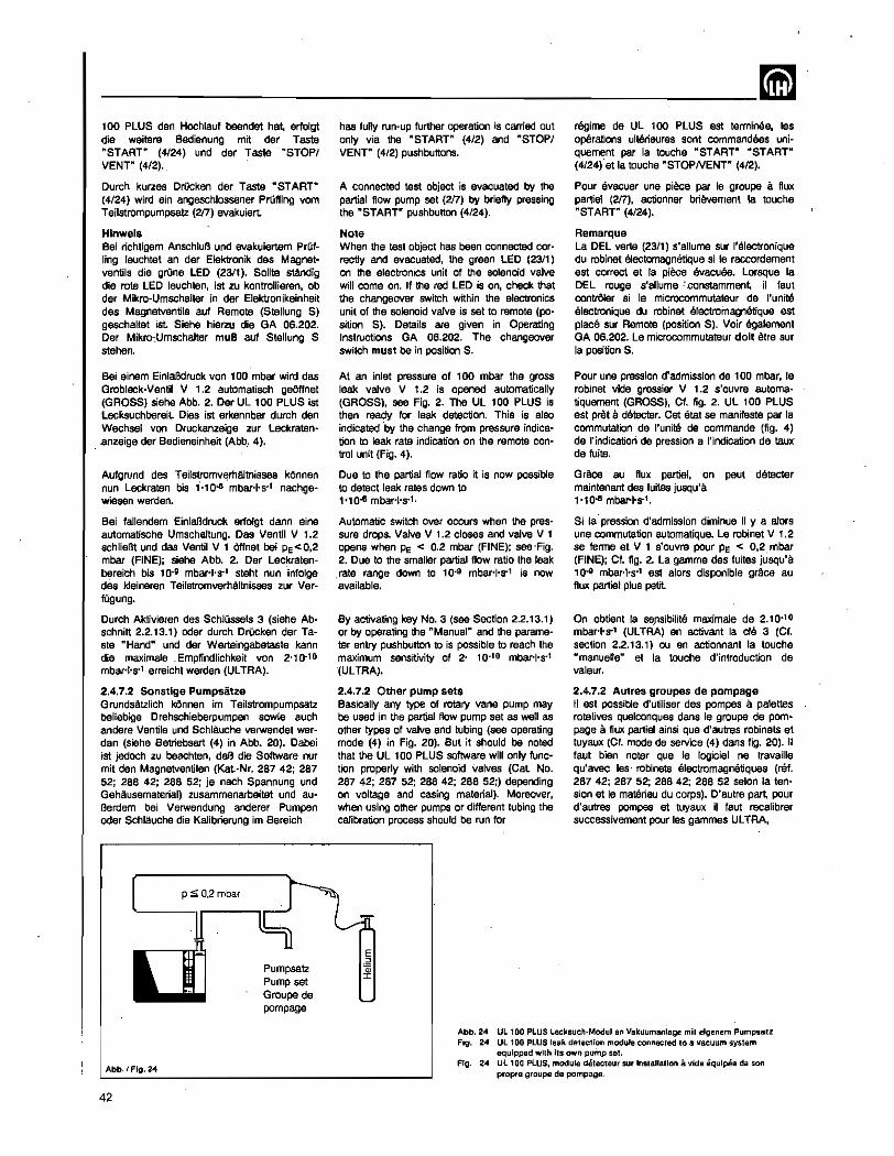
--------------------------~ 100 PLUS den Hochlauf beendet hat, erfolgt die weitere Bedienung mit der Taste "START" (4/24) und der Taste "STOPI VENT" (4/2).
Durch kurzes Dn1cken der Taste "START" (4/24) wird ein angeschlossener PrOfIing vom Teilstrompumpsatz (217) evakuiert.
Hlnwels Bei richtigem AnschluB und evakuiertem PrOfling lauchtet an der Elektronik des Magnetventils die grOna LED (2311). Solita standig die rote LED lauchten, ist zu kontrollieren. ob der -Mikro-Umschalter in der Elektronikeinheit des Magnetventils auf Remote (Stelfung S) geschaltet 1st Siehe hierzu die GA 06.202. Der Mikro~Umschalter muD auf Stellung S stehen.
Bel einem EinlaBdruck von 100 mbar wird das Grobleck-Ventil V 1.2 automatisch geOffnet (GROSS) siehe Abb. 2. Der UL 100 PLUS ist Lecksuchbereit Dies ist erkennbar durch den Wachsel von Druckanzeige zur Leckraten-
. ,anzeige der Badieneinhait (Abb .. 4).
Aufgrund des Tailstromvl;lrhaltnisses kOnnen nun Leckraten bis "'10-8 mbar+s·l nachge· wiesen werden.
Bei fallendem EinlaBdruck elfolgt dann eine automatische Umschaltung. Das Ventil V 1.2 schliellt urid das Ventil V 1 Offnet bei Pe< 0,2 mbar (FINE); siehe Abb. 2. Der Leckraten· bereich bis 10-9 mbar+S"1 steht nun infolge des kleineren Teilstromverhaltnisses zur Verrugung.
Durch Aldivieren des SchlOssels 3 (siehe Abschnitt 2.2.13.1) oder durch DrOcken der Ta· ste "Hand" und der Werteingabetaste kann die maximale _Empfindlichkeit von 2-10.10
mbar+s·1 erreicht werden (ULTRA).
2.4.7.2 Sonstlge Pumpsatze Grundsatzlich kOnnen im Teilstrompumpsatz beliebige Drehschieberpumpen sowie auch andere Ventile und Schlauche verwendet wer· den (siehe Batriebsart (4) in Abb. 20). Dabei ist jedoch zu beachten, daB die Software nur mit den Magnetventilen (Kat.-Nr. 287 42; 287 52; 288 42; 288 52; js nach Spannung und Geh8usematerial) zusammenarbeitet und auI3erdem bei Verwendung anderer Pumpen oder Schlauche die KaJibrierung im Bereich
p ~ 0,2 mbar
has fully run-up further operation is carried out only via the "START" (4/2) and "STOPI VENT" (4/2) push buttons.
A connected test object is evacuated by the partial flow pump set (2/7) by briefly pressing the "START" pushbutton (4/24).
Note When the test object has been connected correctly and evacuated, the green LED (23/1) on the electronics unit of the solenoid valve will come on.' If the red LED is on, check that the changeover switch within the electronics unit of the solenoid valve is sat to remote (po· sition S). Details are given in Operating Instructions GA 06.202. The changeover switch must be in position S.
At an inlet pressure at 100 mbar the gross leak valve V 1.2 is opened automatically (GROSS), see Fig. 2. The UL 100 PLUS is then ready for leak detection. This is also indicated "by the change from pressure indica· tion to leak rate indication on the remote control unit (Fig. 4).
Due to the partial flow ratio it is now possible to detect leak rates down to 1'10-6 mbar+s·1.
Automatic switch over occurs when the pres· sure drops. Valve V 1.2 closes and valve V 1 opens when Pe < 0.2 mbar (FINE); see ·Fig. 2. Due to the smaller partial flow ratio the leak rate range down to 10.9 mbar-I·S"1 is now available.
By activating key No.3 (see Section 2.2.13.') or by operating the "Manual" and the parame· ter entry pushbutton to is possible to reach the maximum sensitivity of 2- 10.10 mbar·1·s·1
(ULTRA).
2.4.7.2 Other pump sets Basically any type at rotary vane pump may be used in the partial flow pump set as well as other types of valve and tubing (see operating mode (4) in Fig. 20). But it should be noted that the UL 100 PLUS software will only funC 8
tion properly with solenoid valves (Cat No. 287 42; 287 52; 2aa 42; 288 52;) depending on voltage and casing material). Moreover, when using other pumps or different tubing the calibration process should be run for
E o
regime de UL 100 PLUS est terminee, les operations ulterieures sont commandees uniQuement par la touche "START" "START" (4/24) e1 10 touche "STOPNENT" (4/2).
Pour avacuer une piece par Ie groupe a flux partie! (217), actionner brievernent la touche "START" (4/24).
Remarque La DEL verte (23/1) s'allume sur I'electronique du robinet electomagnetique si Ie raccordement est correct at la piece evacuee. Lorsque la DEL rouge s'allume.' ,constamment, il faut contrOler si Ie microcommutateur de I'unite electronique du robinet -electroinagnetique est place sur Remote (position S). Voir egalement GA 06.202. Le microcommutateur dolt etre sur la position S.
Pour une pression d'admission de 100 mbar. Ie robinet vide grassier V 1.2 s'ouvre automatiquement (GROSS), Cf. fig. 2. UL tOO PLUS est pret a detecter. cet etal sa manifeste par la commutation de I'unite de commande (fig. 4) de I'indication de pression a I'indication de taUl(
de fuite.
Grace au flux partiel, on peul deteoter maintenant des fuites jusqu'a "1008 mbar-I·S"l.
8i la pression d'admission dirninue iI y a a10rs une commutation automatique. Le robinet V 1.2 se terma et V 1 s'ouvre pour Pe < 0,2, mbar (FINE); Cf. fig. 2. La gamme des tuiles jusqu'a 10-g mOOr'I's" est alors disponible grace au flux partiel plus petit
On obtient la sensibilite maximale de 2.10" 0 mbar·I·S"l (ULTRA) en activant la cle 3 ,(Cf. section 2.2.13.1) ou en actionnant la touche "manuelle" at la touche d'introduction de valeur.
2.4.7.2 Autres groupes de pompage II est possible d'utiliser des pompes a palettes rotatives quelconques dans Ie groupe de pom· page a flux partial ainsi que d'autres robinets et tuyaux (Cf. mode de service (4) dans fig. 20). II taut bien noter que Ie logicisl ne travaille qu'avec les· robinets electromagnetiques (ref. 287 42; 287 52; 2B8 42; 288 52 selon la ten· sion at Ie matSriau du corps). D'aulre part, pour d'autres pampas at tuyaux il faut recalibrer successivement pour les gammes ULTRA,
Pumpsatz ~ Pump set
Abb. I Fig. 24
42
Groupe de pompage
Abb.24 UL 100 PLUS Lecksuct\·Modul an Vakuumanlage mit eigenem Pumpsalz Fig. 24 Ull00 PLUS leak detection module connecled 10 a vacuum syslem
equipped with its own pump sel. Fig. 24 Ul 100 PLUS, module dchecteur sur Inslallatlon a vide equipee de son
propro groupe de pompage.
~-------------------------ULTRA, FINE und GROSS (siaha Abschnitt 2.6) nacheinander durchgefUhrt werden.
2.4.7.3 Betrleb des Lecksuchmoduls ohne Pumpmodul
Die Verwendung des Lecksuchmoduls ohne Pumpmodul (siaha Betriebsart (2) in Abb. 20) ist insbesondere in folgenden FAllen sinnvoll: • im Serviceeinsatz an Vakuumanlagen mit
eigenen Pumpen - an UHV-Anlagen mit niedrigen Drucken, die
nicht durch VorpumpenOI verschmutzt werden sollen
• wenn bereits vorhandene Drehschieberpum· pen als Vorpumpen genutzt werden sollen.
Oas Lecksuchmodul ist unler der Kat.Nr. 155 8a a1s eigenstandige Einheit erhalUich.
Be; UHV-Anlagen hat dies den besonderen Vorteil. daB die Anlage Gberhaupt nicht mit ainer Vorvakuumpumpe verbunden wird und damit kohfenwasserstoffrei bleibt
Urn das Lecksuchmodul in dieser Weise sinzusetzen, ist folgendermaBen vorzugehen: - Lecksuchmodul durch LOsen der beiden
SchnellverschlQsse yom Pumpmodul trennen.
- VorvakuumanschluB des Lecksuchmoduls mit Blindflansch ON 16 KF verschlieBen.
- EinlaB des Lecksuchmoduls mit Vakuumkammer verbinden (hierzu muB an der Vakuumkammer ein Ventil vorhanden seinl).
- Ventil zur evakuierten Vakuumkammer Offnen, so daB LecksuchereinlaB abgepumpt wird.
- SchlOssel Nr. 4 bis zUITJ Anschlag in SchlUs· selschlilz der Bedieneinhelt einstecken.
- Lecksuchmodul mit Netzschalter einschalten und Hochlauf abwarten (bis Exponent aufleuchtet).
- Das Ger!t ist nun meBbereit.
- Die Leckratenanzeige erfolgt nach DrDcken der Taste "START". Durch DrOcken der Taste "STOP" erfolgt in der Statusanzeige im Servicefeld die Anzeige "STBY"; es kann nicht geflutet werden!
- Taste "CAL" (4/11) 3x kurz drOcken.
• Taste "ENTER" (4/13) drOcken und somit den Vorgang bestatigen.
2.4.7.4 Lecksuchmodul mit anderer VOlVakuumpumpe am VorvakuumanschluB
Nachdem das Lecksuchmodul yom Pumpmodul gelOst wurde, staht an der Unterseite des Lecksuchmoduls ein Kleinflansch ON 16 KF zum AnschluB beliebiger Vorpumpen lur VerfOgung (siehe Betriebsart (1) in Abb, 20). Dabei ist lediglich zu beachten, daB der AnschluB von Pumpen mit einem Saugvermogen von mehr als 16 m3'h" nicht sinnvoll ist, da durch die Drosselwirkung des ON 16 KFFlansches dieses SaugvermCigen nichl am EinlaB des Lecksuchers wirksam werden kann,
Die Ablaufsteuerung des Lecksuchers bleibt in dieser Betriebsweise erhalten, d,h. die Bedienung erfolgt in der Oblichen Weise,
ULTRA, FINE and GROSS (see Sec,on 2.6) in that order.
2.4.7.3 Leak Detection Module without Pump Module
The use of the leak detection module without the pump module (see operating mode (2) in Fig. 20) is useful in the following cases: • SeNicing in vacuum systems having their
own pumps - On UHV-systems at low pressures which
are not to be contaminated by the oil of the backing pump
- If already installed, pumps can be used as backing pumps.
The leak detection module is available as a self-conatined unit under Cat. No, 155 83.
In the case of UHV systems this has _ the special advantage that a baCking pump is not required and the UHV system is therefore not contaminated with hydrocarbons,
To use the leal< detection module in this way proceed as follows: - Separate the leak detection module from the
pump by loosening the two quick-release locks.
- Close the forevacuum connection on the leak detection module using a ON 16 KF blind flange.
- Connect the inlet of the leak detection module to the vacuum chamber (this requires a valve a1 the vacuum Chamber!),
- Open the valve to the vacuUI11 chamber so that the leak detector inlet is pumped out
- Insert key No. 4 into the hand unit and activate it right up to the stop.
- Switch on the leak detection module via its mains switch and wait until the run-up phase has been completed. This is indicated by the exponent lighting up.
~ The unit is now ready for taking measurements,
- The leak rate is indicated after operating the nSTART" pushbutton, pressing the pushbutton "STOP" will cause the display to indicate" STByn
; venting is not possiblel
- Briefly press "CAL" (4/11) three times.
- Press "ENTER" (4/13) to acknowledge _the process.
2.4.7.4 Leak Detection Module with an other Backing Pump Connected to the Forevacuum Inlet
After the leak detection module has been separated from the pump module access is gained to the small flange ON 16 KF at the bottom of the unit for connection of any type of suitable backing pump (see operating mode (1) in Fig. 20). It should be noted that the connection of backing pumps with volume flow rates exceeding 16 m3'h-1 is not of additional advantage as higher volume flow rates cannot be effective at the inlet due to the throttling effect of the ON 16 KF flange.
In this operating mode all funtions of the leak detector remain unchanged so that the unit can be operated as usual.
FINE at GROSS (C!. see,on 2.6).
2.4.7.3 SelVlce du module-detecteur sans module-pompa
L'utilisation du module-detecleur sans modulepompa (CF. mode de seNice (2) dans la fig.20) est interessante surtout dans les cas suivants: - intervention dans des installations a vide
ayant leurs propres pompas - installations UV avec basses pressions qui ne
dolvent pas ~e contaminees avec I'huile de la pompe primaire
- lorsque les pampas a palettes rotatives deja installees peuvent litre utilisees comma pampas primaires,
Le module-detacteur est disponible en tant qu'unite independanta $ous la ref. 155 83.
Dans Ie cas des installations UV elles ne sont pas du tout raccordees a. una pompe primaire et restent donc exemptes d'hydrocarbures.
Proc8der de la facon suivante pour utiliser Ie module-detectaur de cette maniere: - Separer Ie module-detecteur du module-· pampa en relachant les daux fermetures
rapides. - EQuiper Ie raccord previde du module-de
tecteur avec une bride aveugle ON 16 KF.
- Raccorder I'admission du module·detecteur avec I'enceinte $ous vide (il taut disposer d'un robinet sur I'enceinte $ous videl).
- Ouvrir Ie robinet vers I'enceinte evacuee de $Orta que I'admission du detecteur soit evacuee.
• Enfoncer la cle no, 4 jusqu'a Is butee dans la fente de I'unite de commande.
- Mettre en service Ie module-detecteur et attendre la mantee (par I'interrupteur sectaur jusqu' a l'aUumage de I'exposant).
• L'appareil est pret a mesurer;
- Actionner la touche .. START" pour obtenir I'indication de taux de fuite. En actionnant 18 touche "STOP" I'affichage d'etat du panneau de service indique "STBY"; la remise a I'air est devenue imposSible! '
- Actionner la touche "CAL" (4/11) 3x brievement.
- Actionner la touche "ENTER" (4/13) pour confirmer I'operation.
2.4.7.4 Module-detecteur avec une autre pompe sur Ie raccord vide prlmalre
Una fois que Ie module-detecteur est separe du module-pompa on dispose d'une petite bride DN 16 KF sur la face infeneure du moduledetecteur pour Ie raccordement de pampes primaires Quelconques (Of. mode de service (1) dans la fig. 20), It faut saulement noter que Ie raccordement de pampas d'un debit superieur a 16 m3'h-1 n'est pas interessant car ce debit ne peut etre effectif a I'admission du detecteuJ vu I'etranglement par la bride ON 16 KF,
Dans ce mode de service toutes les fonctions du detecte-ur restent inchangees c,-a-d. que sa commande se fait de la fsoon habituelle.
43
-------------~ Zu beachten sind jedoch die folgenden EinschrAnkungen bel den Speziftkationen: • die Nachweisgrenze des lecksuchmoduls
erhOht sich ungefAhr proportional zurn angeschlossenen SaugvermOgen der Vorpumpe, d,h. bei 10 x grOBerem SaugvermOgen ist z.B. die kleinste nachweisbare Leckrate nur noch 1'10.9 mbar'I's"
- die StabiHtlit der Anzeige (Rauschen und Driftsn) und damit auch wieder die Nach· weisgrenze hangt unmittelbar von der Qualital dar eingesetzten Vorpumpe abo
Das beste Ergebnis kann mit dam AnschluB ainer (eventuell gedrosselten) Hochvakuumpumpa (Turbopumpe) erzielt werden, da diese im Vergleich zu einer Vorvakuumpumpe erheblich stabiler bzgl. Enddruck und SaugvermOgen fOr Helium ist
Bei einer salchen Pumpa mit groBem SaugvermOgen ist allerdings die Nachweisgrenz8 erheblich Mher (s.o.).
2.4.8 Schnuffellecksuche An den UL 100 PLUS kOnnen folgende SchnOffeleinrichtungen angeschl. werden:
Helium-Standard-SchnUffier ST 100 Helium-Schnuffler aUICKTEST QT 100
In allen FAllen wird der jeweilige SchnOffier an den BnlaB des Lecksuchers angeschlossen. Der Schnuffelbetrieb kann wie im Abschnitt 2.2.13.1 beschrieben mit SchlOssel Nr. 6 angewahlt werden.
Wurde der Lecksucher im Hochlaufen initialisiert, oder war er vor dem Ausschalten im SchnOffelbetrieb, gelangt er automatisch in den Mel3betrieb.
Sonst ist ein zusatzliches DrOcken der Taste "START" (4/24) erforderlich.
Wenn der Lecksucher betriebsbereit ist, erscheint auf der Leckratenanzeige der Wert fUr das natorliche Lufthelium.
Dieser Wert kann bei einigen 10-& mbar+s-1
liegen.
Die Kalibrierung erfolgt genauso, wie baim normaJen Kalibrieren mit externem Testlack (sieha Abschnitt 2.6.3).
Entschaidend 1st aber nun, daB die einmal durchgefUhrte Kalibrierung nur fur die gewahlten 'SchnUffelbedingungen (Abstand und Geschwincligkeit bezugtich der Leckposition) gilt.
FOr eventuelle Korrekturfaktoren in Bezug der Haliumkonzentrationen ·unter 100 % oder un-1erschiedlicher PrOflingsdrOcke siehe die Gebrauchsanweisung des verwendaten SchnOffler.
Der Kalibrierfaktar und die gewahlte Betriebsart "SNIFF" bleiben auch nach dem Ausschalten des GerAtes erhalten.
1m MeBbetrieb ist die Taste "STOP I VENT" verriegelt Durch emeutes Steeken von SchlOssel Nr. 6 und DrOcken der Taste "ENTER" wird die Schnuffelfunktion aufgehaben. Das GerAt geht dann in den Stand-Byzustand.
44
However the following restrictions in the specifications should be noted:-- the detection limit of the leak detection mod
ule increases approximately in proportion to the volume flow rate of the pump connected, i.e., for ten times the volume flow rate the detection limit is only 1'10.9 mbar-I's-1
- the stability of the readings (noise and drifts) and thereby the detection limit depend directly on the quality of the- backing pump used.
The best results may be obtained by using a (posSibly throttled) high vacuum pump (turbopump), as this type of pump exhibits a much more stable volume flaw rate for helium and ultimate pressure than a backing pump.
When using such a pump with a high volUme flow rate the detection limit is Considerably increased (as mentioned above).
2.4.8 Sniffing Leak Test All LH sniffer probes can be conneeted to the UL 100 PLUS, these being:
Helium Standard Sample Probe ST 100 Helium Sample Probe QUICKTEST QT 100
In all cases the corresponding sniffer is connected to the inlet of the leak detector. Key No.6 is used as described in Section 2.2.' 3.1 to set up the sniffer mode.
If the leak detector was inittalized during runup or was in the sniffer mode when switching off it is automatically set to the measurement mode when switching on again.
Otherwise pUShbutton "START" (4/24) must be operated in addition.
When the leak detector is ready the leak rate display wlll indicate the natural helium concentration of the air.
This value may be equivalent to a leak of 10-& mbar·l·s·1.
Calibration is' performed in the same way as for normal calibration with an external calibrated leak (see Section 2.6.3).
The decisive point in this is that the once per· formed calibration only applies for the selected conditions of calibration (distance and velocity with respect to the position of the leak).
For possible correction factors because of he· lium concentrations below 100 % or different pressures within the test objects please refer to the Operating Instructions of the sniffer probes used.
The calibration factor and the selected operating mode "SNIFF" remain in the memory even after switching off.
In the measurement mode the "STOPNENT" pushbutton is blocked. This key·invoked sniffer function is disabled again by inserting key No. 6 and pressing the "ENTER~ pushbutton. The unit then reverts to the standby mode.
II faut cependant noter les restrictions des sp6cificatians suivantes: - la limite de detection du module detecteur
augme"nte de fayon sensiblement propor· tionnelle au debit raccorde de la pompe primaire, c.-a·d. qu'un debit dix faix plus important reduit p. eX. la plus petite fuite decelable a une valeur de ,'10.9 mbar'I's-1
. la stabilite de I'affichage (bruits et derives), et donc egalement la limite de detection, depend directement de la qualite de la pompe primaire utilises.
Le meiUeur resultat paut eire obtenu avec Ie raccordement d'une pompe a vide pousse (tur· bopompe eventuertement etranglee) car celle-cj presente une stabilite, pour la pression limite at Ie debit d'helium, sensiblement plus importante que dans Ie cas d'une pompe primaire.
Cependant pour une 1elle pompa Ii grand debit la limite de detection est bien plus elevee (voir ci·dessus).
2.4.8 Detection avec renlfleurs On paut raccorder les renifleurs suivants a UL 100 PLUS:
Renifleur Ii helium standard ST 100 Renifleur a helium rapide aUICKTEST QT 100.
Oans tous les cas, Ie renifleur en question est raccorde a I'admission du detecteur. Utiliser la cle no. 6 comme decrit dans fa section 2.2.13.1 pour selectionner Ie mode renifleur.
Le det~teur passe automatiquement au mode mesure·s'jj a ete initialise pendant la montee en regime au s'il etait en mode renifleur avant la mise hors circuit
Sinon 11 est necessaire d'actionner encore une fois la touche "START" (4/24).
Lorsque Ie detecteur est en ordre de marche, I'affichage des taux de fuite indique la concentration normale d'helium dans I'air.
Catta valeur est de I'ordre de quelque 10-& mbar+s·'.
Le calibrage sa fait axactement comme Ie calibrage normal avec fuite calibres externe (CF. section 2.6.3).
Le point capital est que ce calibrage une fois execute, i1 ne vaut que pour les conditions precises du reniflement (distance et vitesse par rapport a la position de 18 fuits).
Pour les facteurs de correction eventuels, pour les concentrations d'helium < 100 % au pour differentes pressions des pieces, voir Ie mode d'emploi correspondant au renifleur.
Le facteur de calibrage et Ie mode "SNIF" per· sistent meme apres la mise hors circuit de I'appareil.
En mode mesure, la touche "STOPNENT" est verrouillee. En enfonyant a nouveau la cle 6 et en actionnant la touche "ENTER" on annule la fonction reniflement L'appareil passe en mode Stand·By.
~------------------------~ 1m Schnuffelbetrieb kann der Femsteuereingang "PUMPEN", Pin Nt. 18 der Multifunktionsschnittstelle zur Helium-Untergrundbestimmung genutzt werden. Dazu muB ain Schalter im SchnOffelspitzen-Haiter montiert und mit dam 'Fernsteuereingang zwischen Pin Nt. 16 und Pin Nt. 18 der Multifunktionsschnittstelle verbunden werden.
Di8 Funktion dieses Fernsteuereinganges ist vergleichbar mit der Nullpunkt-Taste (4/14) der Bedieneinheit (Abschnitt 2.2.6).
Der Schalter muB SO eingebaut werden, daB bei Entnahme der SchnUffelspitze 8US der Hal· terung der Kontald geOffnet und somit der Heliumuntergrund unterdrUckt wird.
Die Helium-UntergrundunterdrOckung wird dutch die blinkende Null-Indikator LED (4/21) angezeigl
2.4.8.1 Lecksuche mit Standard· sChnuffler
Der StandardschnUffler wird dann eingesetzt, wenn hOchste Empfindlichkeit verlangt wird. Er hat zudem den Vorteil, kein Gas in nennenswerter Menge abzusaugen.
Deshalb ist er besonders gut fOr HOlientest's oder zur Messung sehr kleiner Lecks geeignet
2.4.8.2 Lecksuche mit Hellum-Schnuffler QUICKTEST QT 100
Der Helium-SchnOffier QUICKTEST aT 100 vermeidet die Beschrankung des StandardschnOffiers auf kurze Leitungsll:lngen. Durch seinen Ansaugeffekt hat er den Vorteil, auch . Leeks anzuzeigen, die ralativ weit von dar SchnOffalspitze entfernt sind.
Er ist dashalb besonders gut fOr die Leckloka· lisierung ainzusatzen.
2.5 AuBerbetriebsetzung Zur AuBerbetriebsetzung ist der Netzschalter ~EIN/AUS" (817) auf Stellung "AUS" zu schalten. Weitere MaBnahrnen sind nicht erforderlich.
Die Betriebsart wird gespeichert. Das Gerat nimmt nach Wiederinbetriebnahme den glejchen Zustand wieder ein.
Hinwels .Das Gasballastventil der TRIVAC 0 1,6 B (siehe Abschnitt 3.2.1) muB zum Transport immer geschlossen werden.
In the sniffer mode 'It is possible to utifize the remote control input"PUMPING", pin No. 18 on the multifunction interface to determine the helium background. For this it is required to mount a switch in the holder for the sniffer probe which is connected to the remote control input between pin No. 16 and pin No. 18 of the multifunction interface.
The function of this remote control input is comparable to that of the aulozero pushbutton (4/14) on the hand unit (see Section 2.2.6).
The switch must be installed in such a way, that the contact opens when the sniffer probe is taken out, so that the helium background is suppressed at that time.
This is indicated by a flashing zero indication LEO (4/21).
2.4.8.1 Leak Testing with Standard Sniffer
The standard sniffer probe is always used when the highest sensitivity is required. It also h~ the advantage that gas intake is very low.
It is therefore especially well suited for hood tests or for the measurement of vB!'{ frne leaks.
2.4.8.2 Leak Detection with the aUICKM :rEST aT 100 Sniffer Probe
The QUICKTEST aT 100 avoids the limitations of the standard sniffer conceming the length of the sniffer line. Due to its sucking effect it has the additional advantage of bein9 able to indicate, any leaks fairly far apart from the probe tip.
Therefore it is especially well suited for the localization of leaks.
2.5 Switching Off To switch off the UL 100 PLUS, set the "ON/OFF" power switch (BIl) to the "OFF" position. No other action is necessary.
The operating mode is stored. -The instrument reverts to the same operating mode when it is switched on again.
Note The gas ballast valve of the TRIVAC D 1.6 B (see Section 3.2.1) must always be closed during transport.
En mode renifleur, rentree de telecommande "POMPER", broche no. 18 de I'jnterface multifonction paUl selVir a determiner Ie fond hBlium. II faut pour eela manter un commutateur sur i!3 support de la pointe du renifleur et Ie relier avec I'entree de telecommande entre broche no. 16 et broche no. 1B de I'interface multifonctlon.
Cette fonction de I'entree de telecommande est comparable a celie de la touche de remise a zero (4/14) de I'unite de commande (section 2.2.6).
Le commutateur doit etre monte de· telle maniare que Ie contact s'ouvre, en annulant Ie fond Mlium, lorsqu'on retire de son support la pointe du renifleur.
La suppression du fond helium est indiquee par Ie clignotement de la DEL zero (4/21).
2.4.8.1 Detection avec renifleur standard
II s'utilise toujours pour obtenir la plus haute sensibilit9. II a d'autre part I'avantage de ne pas aspirer de gaz en quantite notable.
C'est pourquoi iI est particulierement approprie pour Ie test sous enveloppe au pour la mesure de fuites particuliarement petites.
2.4.8.2 Detection avec Ie renifleur rapide QUICKTEiWOT 100
II n'est pas contraint comme Ie renifleur standard a de courtes distances. Avec son eftet aspirant iI presente I'avantage d'indiquer des fuites relativement eloignees de la pointe du renifleur.
II est done particulerement approprie a la localisation des fuites.
2.5 Arret de I'appareil Commuter "interrupteur "MARCHEtARRET" (BIl) sur la position" ARRET". D'autres mesures ne sont pas necessaires.
Le mode de service est memorise. L'appareil rep rend Ie m~me etat quand if est remis en circuit
Remarque Le robinet de lest d'air de TRIVAC 01,6 B (voir section 3.2.1) doit toujours atre ferme pour Ie transport
45
~----------_______________ mm 2.6 Kallbrleren und Tunen Der UL 100 PLUS ist zur Quantitativen Leck~ ratenmessung geeignet Dazu ist ain Kalibrier· faktor erforderlich, der vern UL 100 PLUS bairn Kalibrieren automatisch errechnet und gespeichert wird. Die Kalibrierung vom UL 100 PLUS wire! zudem durch die Verwendung aines internen Testlecks (Einbautestleck TL 7) wesentlich vereinfacht. 1st im UL 100 PLUS keln Testleck eingebaut, muB die Kalibrierung mit einem externen Testleck 8OOlgen.
Hlnwels - Die Kalibrierung solite erst 15 min naoh Be
endigung des Hochlaufs erfolgen u. nach ca. 2 Stunden ainmal wiederholt werden.
- Die durch die Kalibrierung ermittelten Kali· brierfaldoren bleiben auch· nach dam Ausschalten des Gerates erhalten.
Es werden vier Kalibrierfaktoren gespeichert: • F_'·GROSS • F_,·FINE - Faktor-ULTRA - Falder-SNIFF
Bairn Kalibrieren in ULTRA warden dia Fakto· ran GROSS und FINE aus dam Faktor· ULTRA barechnet Diasa Umrechnung ist nur fOr ainen Betrieb mit der Option "Teilstrom· pumpsatz mit 0 25 B" gOltig. Beim Betrieb mit beliebigen Anlagen oder Teilstrompumpan muB zusatzlich in den Bereichan GROSS und FINE kalibriert werden.
Der analoge Signalausgang (Abschnitt 2.2.13.6) bzw. die V.24-Schnittstelle bieten
. zur Erstetlung der Kafibrierleckrate eine bessare Aufl6sung als die Kombi-Anzeige der Bedienainheit. Die Leckrate kann bel Benutzung der V.24-Schnittstelle durch DrOcken der Taste "START" an ein Terminal oder Drucker ausgegeben werden.
Vor jedem Kalibriervorgang soUte ein TUNEVorgang durchgefOhrt werden.
2.6.1 Tunen Der Tune-Vorgang dient zum Abgleich des Massenspektrometers auf maximale Empfindlichkeit. Dazu wird die Beschleunigungsspannung der lonen im gewahlten Massebereich variert, bis ein maxi maier lonenstrom am 10-nenfAnger registriert wird.
Zurn Tunen muB die Elektronikeinheit mit dem Servicefeld ausgeklappt werden 'und das Testreck ge6ffnet sain.
Das Massenspektrometer kann jetzt mit Potentiometer "M4" (26/12) auf max. Empfindlichkeit gebracht werden. Die Leckratenanzeige wird dann maximal.
2.6.2 Kalibrieren mh elngebautem Test-leck
UL 100 PLUS mit der Taste "STOPNENT" in den Zustand Standby oder Fluten bringen.
Mit Multifunktionstaste "Trigger und Kalibrierung" das Kalibrieren anwahlen und mit der Taste "ENTER" quittieren.
Auf der Statusanzeige (26/1) im Servicefeld erscheint "CAL". Oas interne Testleck Offnet hOrbar.
46
2.6 Calibration and tuning The UL 100 PLUS is suitable for quantitative leak rate measurements. This requires a Calibration factor, which is automatically calculated and stored by the UL 100 PLUS during calibration. Calibration of the UL 100 PLUS is greatly simplified by the use of an internal calibrated leSk. If the UL 100 PLUS is not equipped with a calibrated leak, calibration must be carried out with an external calibrated leak.
Note - Calibration should not take place until 15
min after run-up and should be repeated once after approx. 2 hours.
- The factors determined during the calibration process remain stored even after switching off.
Four calibration factors are stored: • facto, • GROSS - factor - FINE - factor - ULTRA - factor - SNIFF
During calibration in the ULTRA range, the factors GROSS and FINE are computed based on the ULTRA factor. This computation applies only for operation with the option "partial flow pump set with 0 25 B". For operation with any other type of system or other partial flow pump it is essential to calibrate the ranges FINE and GROSS in addition. "
The analogue signal output (Section 2.2.13.6) or the V.24 interface offer a higher resolution compared to the combined indicator on the hand unit When using the V.24 interface it is poSsible to output the leak rate once to a terminal or a computer by pressing the "START" pushbutton.
The TUNE process should be run before each calibration.
2.6.1 Tuning The tuning process helps to align the mass spectrometer so that its maximum sensitivity is obtained. For this "the accelerating voltage for the ions in the mass spectrometer is varied in the selected mass range, until a maximum ion current is registered at the ion cottector.
For tuning it is required to fold out the electronics unit with the service panel and to open the calibrated leak.
Now the sensitivity of the mass spectrometer may be set to maximum by operating potentiometer "M4" (26/12). The leak rate display will also show a maximum.
2.6.2 Calibration with the bUilt-in cali-brated leak
Set up the UL 100 PLUS to standby or venting by pressing the "STOPNENT" button.
Use the multifunction pushbutton "Trigger and Calibrate" to select the calibrate mode and acknowledge this by pressing the "ENTER" pushbutton.
The status display (26/1) on the service panel will read "CAL". The internal calibrated leak opens audibly.
2.6 Callbrage et syntonlsatlon Le detecteur UL 100 PLUS pennet la mesure quantitative des taux de fuite. Ceci necessite un facteur de calibrage calcule automatiquement at memorise par Ie detecteur lors du calibrage. Cette operation est tres simplifiee par I'emploi d'un~ fuite calibres interne. Si aucune fuite calibree n'est integree dans Ie detecteur UL , 00 PLUS, ce calibrage doit alors etre execute au moyen d'une fuite calibree externe.
Remarque • Ne pratiquer Ie calibrage que 15" minutes
apres la fin de la mantee en regime. Le repeter apree environ 2 heures.
- Les facteurs determines par Ie calibrage sont conserves meme apres la mise hors circuit de l'appareU.
Ouatre facteurs de calibrage sont memorises: - facteur GROSS - facteur FINE - facteur ULTRA • lactou' SNIFF
Pour Ie calibrage en ULTRA, les facteurs GROSS et FINE" sont calcutes a partir du facteur ULTRA. Cetta conversion n'est vatable que pour un service avec I'option "groupe de pompage a flux partiel avec 0 25 B". Avec d'autres installations ou pampes a flux partiel il faut egalement calibrer dans les gammes GROSS at FINE.
Pour obtenir Ie taux de fuite calibre, la sortie de signal analogique (section 2.2.13.6) ou I'interface V.24 offrent une memeure resolution que I'affichage combine de I'unite de comman· de. Avec I'interface V.24, on peut sortir Ie taux de fuite sur un terminal ou une imprimante en actionnant la touche "START".
II est preferable d'effectuer une syntonisation avant chaque calibrage.
2.6.1 Syntonisation La syntonisation sert a equilibrer Ie spectrometre de masse sur la sensibilite maximale. On fait varier [a tension d'acceleration des ions dans la gamme de masse choisie jusqu'a I'enregistrement d'un courant ionique maximal sur Ie colleeteur d'ions.
Pour fa syntonisalion i1 faut que I'unite electronique avec Ie panneau de commande soit basculee at que la fuite calibree soit ouverte.
Le spactrometre de masse paut maintenant etre regie par Ie potentiometre "M4" (26112) sur sensibilite maximale. L'affichage du teux de fuite sort egalement un maximum.
2.6.2 Callbrage avec fuite calibree Incorporee
Mettre UL 100 PLUS dans I'etat Stand-By ou remis a I'atmosphere avec Ie touche "STOPNENT".
Setectionner Ie calibrage avec la touche multifonction "trigger et calibrage" et confirmer avec la touche "ENTER".
"CAL" apparait sur I'indicateur d'etat (26/1) du panneau de commande. On entend distinctement I'ouverture de la fuite calibree inteme.
~-------------------------Das Massenspektrometer kann jetzt mit Potentiometer .. M4" (26/12) auf max. Empfindlichkeit gebracht werden. (Abschnitt 2.6.1). Die Leckratenanzeige wird dann maximal.
Durch DrOcken der Taste ZERO kann nun' der gerateinterne Untergrund bestimmt werden.
- Vor der Untergrundbestimmung schlieBt das Testleck.
- Nach der Untergrundbestimmung affnet das Testleck.
Durch DrOcken der Werteingabetasten (4/19) und (4/6) wire! die auf dam Testleck 8ufgedruckte Leckrate eingestellt
Der Kalibriervorgang ist nach dam DrOcken der Taste "ENTER" abgeschlossen. Das interne Testleck schlieBt horbar.
Der Faktor-ULTRA ist damit bestimmt. Die Faktoren GROSS und FINE werden aus dam Faktor-ULTRA berechnet.
Bel zu geringer Empfindlichkeit kann beim Kalibrieren mit der Taste "HAND" auf die andere Katode umgeschaltet werden.
Der Kalibriervorgang kann jederzeit durch DrOcken der Taste "Trigger. und Kalibrierung" abgebrochen werden.
2.6.3 Kallbrieren mit externem Testleck
Externes Testleck offnen
UL 100 PLUS mit der Taste "START" in den Zustand Messen bringen.
Mit Multifunktionstaste "Trigger und Kalibrierung" das Kalibrieren anwahlen und mit der Taste "ENTER" quittieren.
Auf der Statusanzeige (26/1) im Servicefeld erscheint "CAL".
Das Massenspektrometer kann jetzt mit Potentiometer "M4 n (26/12) auf max. Empfindlichkeit gebracht werden. (Abschnitt 2.6.1). Die Leckratenanzeige wird dann maximal.
Extemes Testleck sehlieBen
Einen vorhandenen Untergrund mit der Nullpunkt-Taste (4/14) unterdrOcken.
Externes Testleck Offnen.
Durch DrOeken der Werteingabetasten (4/19) und (4/6) wird die auf dem Testleck aufgedruckte Leckrate eingestellt.
Der Kalibriervorgang ist nach dem DrOcken der Taste "ENTER" abgeschlossen.
1m Normalbetrieb ist der Faktor-ULTRA damit bestimmt Die Faktoren GROSS und FINE werden aus dem Faktor-ULTRA berechnet.
1m Teilstrombetrieb (siehe die Betriebsarten (3) und (4) in Abb. 20) kennen die Kalibrierfaktoren GROSS, FINE und ULTRA einzelnen bestimmt werden. Dazu muB vor dem Kalibrieren durch DrOcken der Taste "HAND" die automatische MeBbereichswahl ausgeschaltet werden. Durch DrOcken der Werteingabetasten (4/19) und (4/6) kann der entsprechende MeBbereich angewahlt werden. Hierzu muB
Now the sensitivity of the mass spectrometer may be set to maximum by operating potentiometer "M4" (26/12) (Sec. 2.6.1). The leak rate display will also show a maximum.
Now it is possible to determine the internal background by pressing the ZERO pushbut· ton. - The calibrated leak closes before the back
ground is determined .. - After the background has been determined
the car,brated leak opens.
The leak rate which is imprinted on the calibrated leak is entered via the parameter entry pushbuttons (4/19) and (4/6).
Pressing the "ENTEW pushbutton terminates the calibration process. The internal calibrated leak closes. audibly.
In this way the ULTRA factor has been determined. The factors for FINE and GROSS are computed based on the ULTRA factor.
When the sensitivity is too low during calibration it is possible to manually switch over to the other cathode by pressing the "MANUAL" pushbutton.
The calibration process may be terminated at any time by pressing the "Trigger and Calibrate" pushbutton.
2.6.3 Calibration with an external cali-brated leak
Open the external calibrated leak.
Set up the UL 100 PLUS to the measure mode by pressing the "START" pushbutton.
Use the multifunction pushbutton "Trigger and Calibrate" to select the calibrate mode and acknowledge this by pressing the "ENTER" pushbutton.
The status display (26/1) on the seNice panel will read "CAL".
Now the sensitivity of the mass spectrometer may be set to maximum by' operating potentiometer "M4" (26/12) (se.e Section 2.6.1). The leak rate display will also show a maximum.
Now close the external calibrated leak.
Suppress any existing background by operating the autozero pushbutton (4/14).
Open the external calibrated leak.
The leak rate which is imprinted on the calibrated leak is entered via the parameter entry pushbuttons (4/19) and (4/6).
Pressing the "ENTER" pushbutton terminates the calibration process.
In this way the ULTRA factor has been determined. The factors for FINE and GROSS are computed based on the ULTRA factor.
In the partial flow mode (see operating modes (3) and (4) in Fig. 20) it is possible to separately determine the calibration factors GROSS, FINE and ULTRA. To do this, it is first of all required to switch off the autoranging function by operating the "MANUAL" pushbutton. Operation of the parameter entry pushbuttons (4/19) and (4/6) selects the required measurement range. For this the
On peul alors regler Ie spectrometre de masse sur la sensibilite maximale avec Ie potentiomalre n M4" (26f12). (Of. section 2.6.1). L'indication du taux de fulte est a10rs maximale.
L'actionnement de la touche ZERO permet ensuite de detinir Ie fond Mlium interne de I'apparei!. - la fuite calibree sa ferme avant la determina
tion du fond, - apras la determination du fond, la fuite cali
bree s'ouvre a nouveau.
On regie ensuite Ie taux de fuile inscrit sur la fuite calibree a I'aide des touches d'introduction de valeurs (4/19) at (4/6).
Apres I'actionnement de la touche "ENTER". Ie catibrage est termine. On entend la fermeture de la fuite calibree interne.
le facteur ULTRA est ainsi determine. Les facteurs GROSS et FINE sont calcules a partir du facteur ULTRA.
Si la sensibilite est trap faible, on peut passer, pour Ie calibrage, a I'autre cathode avec la touche "manuerte".
L'interruption du calibrage est possible a tout moment avec la touche "trigger et calibrage".
2.6.3 Calibrage avec une fulte calibree externe
Ouvrir la fuite calibree externe.
Placer UL 100 PLUS dans I'etat mesure avec la touche n START".
Selectionner Ie calibrage avec la touche multifonction "trigger et calibrage" et confirmer avec la touche "ENTER".
~CAL" apparait sur I'indicateur d'etat (2611) du panneau de commande.
On paut alors regler Ie spectrometre de masse sur la sensibilite maximale avec Ie potentiomatre "M4" (26/12) (Cf. section 2.6.1). L'indication du taux de fuite est a10rs maximale.
Raccorder la fuite calibres externe.
Corriger ensuite un eventuel fond helium en actionnant la touche ZERO (4/14).
Ouvrir la fuite calibree externe.
On regie ensuite Ie taux de fuite inserit sur la fuite calibree a I'aide des touches d'introduction de valeurs (4/19) at (4/6).
Apres I'actionnament de la toucha "ENTER", Ie calibrage est termine.
En service normal Ie facteur ULTRA est ainsi determine. Les facteurs GROSS at FINE sont calcules a partir du faeteur ULTRA.
En service a flux partiel (Cf. les modes (3) et (4) dans la fig. 20) les facteurs de calibrage GROSS, FINE et ULTRA pewent etre determines separement II faut pour cela couper la selection automatique des gammes de mesure en actionnant la touche "manuelte" avant Ie calibrage. La gamma de mesure desiree se cholsit alors par les touches d'introduction de valeurs (4/19) et (4/6).11 faut pour cela que
47
~------------------------~ das Servicefeld mit Elektronik~Einheit ausgeklappt werden.
ULTRA· V1 und V2 geOffnet FINE - V1, V2 und Veld geOffnet GROSS- V1.2, V2 und Vext geOffnet
(Veld = extemes Teilstromventil von der Option "Teilstrompumpsatz")
Die Kalibrierfaktoren sollten in folgender Reihenfolge bestimmt werden: ULTRA mit TL 8, FINE mit TL 8 und GROSS mit TL 4-6.
Oas Testlack TL 4-6 kann dazu in FINE kaJibriert werden.
FOr jaden Kalibrierfaktor ist aine Kalibrierung notwendig.
Der' Abgleich des Massenspektrometers darf dabei abeT nur ainmal 81101gen.
Bei zu geringer Empfindlichkeit kann beim KaUbrieran mit dar Taste "HAND" aut die andere Katode umgeschaltet werden.
Oar Kalibriervorgang kann jederzeit dUTCh OrOcken dar Tasten "STOP" odar "Trigger und Kalibrierung" abgebrochen werden.
2.6.4 Kallbrieren 1m Schnuffelbetrleb SchnOffelspitze in die Luft halten.
Mit Multifunktionstaste "Trigger und KaJibrierung" das Kalibrieren anwahlen und mit der Taste "ENTER" quittieren.
Auf der Statusanzeige (26/1) im Servicefeld erSCheint "CAL".
Einen vorhandenen Untergrund mit der Nullpunkt-Taste (4/14) unterdrOcken.
SchnOffelspitze YOr die Offnung des SchnOffelTestlecks halten.
Durch OrQcken der Werteingabetasten (4/19) und (4/6) wire! die auf dem Testlack aufgedruckte Leckrate eingestellt
Der Kalibriervorgang ist nach dem Dn1cken der Taste "ENTER" abgeschlossen.
Oer Faktor-SN1FF ist damit bestimmt
Bei zu geringer Empfindlichkeit kann bairn Kalibrieren mit der Taste "HAND" auf die andere Katode umgeschaltet werden.
Der Kalibriervorgang kann jederzeit durch DrOcken der Taste "Trigger und Kalibrierung" abgebrochen werden.
48
electronics unit with the service panel must be folded out.
ULTRA ~ V1 and V2 open FINE - V1, V2 and Veld open GROSS - V1.2, V2 and Veld open
(Veld = external partial flow valve of the optional partial flow pump set)
The calibration factors should be determined in the following order: ULTRA with TL 8, FINE with TL 8 and GROSS with TL 4-6.
For this the calibrated leak TL 4-6 may be calibrated in the FINE range,
Each calibration factor requires its own calibration run.
However, the mass spectrometer may only be aligned once.
When the sensitivity is too low during calibration it is possible to manually switch over to the ott,er cathode by pressing the "MANUAL" pushbutton.
The calibration process may be terminated at any time by pressing the pushbuttons "STOP" or "Trigger and Calibrate".
2.6.4 Calibration In the snlfler mode Hold the tip of the sniffer up into the air.
Use the multifunction pushbutton "Trigger'and Calibrate" to select the calibrate mode and acknowledge this by pressing the "ENTER" pushbutton.
The status display (26/1) on-the service panel will read "CAL".
Suppress any existing background by operating the autozero pushbutton (4/14).
Hold the tip of the sniffer in front of the opening of the sniffer calibrated leak.
The leak rate which is imprinted on the calibrated leak is entered via the parameter entry pushbuttons (4/19) and (4/6).
Pressin'g the "ENTER" pushbutton terminates the calibration process.
This completes the determination of the SNIFF factor.
When the sensitivity is too low during calibration it is possible to manually switch over to the other cathode by pressing tha "MANUAL" pushbutton.
The calibration process may be terminated at any time by pressing the "Trigger and Calibrate" pushbutton.
Ie panneau ,de commande avec ['unite electronique soit bascule.
ULTRA - V1 et V2 ouverts FINE - V1, V2 et Veld ouverts GROSS- V1.2, V2 Veld ouverts
(Vext : robinet eld. flux partiel de I'option "groupe de pompage a flux partiel)
Les facteurs de calibrage doivent etre determines dans I'ordre suivant ULTRA avec TL8, FINE avec TL8 et GROSS avec TL 4·6.
Pour cela on peut calibrer la fuite calibres TL 4-6 dans FINE.
Un calibrage est necessaire pour chaque facteur de calibrage.
Cependant, Ie calibrage du spectrometre de masse ne doit ette effectue' qu'une saule fois.
Si'la sensibilite est trop faible, on paut passer, pour Ie calibrage, a I'autre cathode avec la touche "manuerle".
L'interruption du calibrage est possible a tout moment avec les touches "STOP" au "trigger at calibrage".
2.6.4 Callbrage en mode renifleur Maintenir la pointe du renifleur dans I'air.
Selectionner Ie calibrage avec la touche multifonction "trigger et calibraga" et confirmer avec la touche "ENTER".
"CAL" apparait sur I'indicateur d'etat (26/1) du panneau de commande.
Carriger un eventuel fond helium avec la touche zero (4114).
Placer la pointe du renifleur devant I'ouverture de la fuite calibree pour renifleur.
On, regie ensuite Ie taux de fuite inscrit sur la fuite calibree a I'aide des touches d'introduction de valeurs (4/19) et (4/6).
Apres ['actionnement de la touche "ENTER", Ie calibrage est termine,
Le facteur SNIFF est ainsi determine.
SI la sensibilite est trap faible, on paut passer, . pour. Ie calibrage, a I'autre cathode avec la touche "manuelle".
L'interruption du calibrage est possible a tout moment avec la touche "trigger et calibrage".
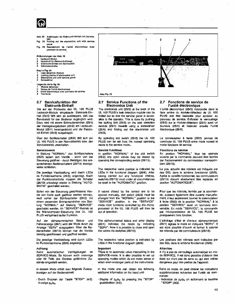
mm ________________ ~--------Abb. 25 Auskleppen der Elektronlk-Elnlielt mil Servlc.
laid Fig. 25 Folding out the electronlC5 unit with service
panal Fig. 25 Basculement de I'unlte electroniqu8 avec
panneau de servlce,
Erlluterungen ;cur Abb. 25 1 Lecksuch-Modul 2 VerschluB lur Elektronlk-Elnlleit 3 Elektronik·Elnhelt mit Servlceleld 4 Scllraubendreher
Key to Fig. 25 1 leak detection module 2 Locking device of electronics unit 3 Electronics unit with service panel 4 Screwdriver
legende de la fig. 25 , Module detecteur 2 Verrou de I'unlte eleclronique 3 Unite eleclronlque avec panneau de service. 4 Tournevis
2.7 Servlcefunktlon der Elektron ik-Elnhelt
Die auf dar Ruckseite des UL 100 PLUS Lecksuch-Moduls eingebaute Elektronik-Einheit (25/3) laBt sich so ausklappen, daB das Servicefeld fOr den Bediener zuganglich wird. Dazu wird mit elnem Schraubendreher (25/4) dar VerriegeJungsbolzen (25/2) am LecksuchModul (2511) hereingadnickt und die Elektronik-Einheit (25/3) ausgeklappt.
Ober den Schlitzschalter (26/2) laBt sich der UL 100 PLUS in den Normalbetrieb bzw. den Servicebetrieb umschalten.
SQrvicQZWQck In SteHung "NORMAL" des Schlitzschalters (26/2) lassen sich Ventile - wenn von der Steuerung getiffnet - durch Betatigen des ent- . sprechenden Bedienschalters (26/13) zwangsweise schlieBen.
Die jeweUige VentilsteUung wi(d durch LEOs im Funktionsschema (26/6) angezeigt. Nach der Funktionskonlrolle mussen die Schaller (26/13) unbedingt wieder in Steflung "AUTOMATIK" geschaltet werden.
Sollen von der Stauerung gaschlossene Ventile von Hand auch ge6ffnet werden k6nnen, muB vorher der Schlitzscf:lalter (26/2) mit einem passenden Schraubendreher von Stellung' "NORMAL" auf SteJlung "SERVICE" gaschaltet werden. 1m "SERVICE"-Betrieb ist die Mikrocomputer-Steuerung des UL 100 PLUS weitgehend aul3er Funktion.
Auf der alphanumerischen Status- und Fehleranzeige (2611) wird der Mode durch die Anzeige "SERV" ausgegeben. Ober die Bedienschalter (26/13) kOnnen nun die Ventile beliebig geschlossen und ge6ffnet werden.
Die jeweilige Venlilsteflung wird durch LEOs im Funktionsschema (26/6) angezeigt.
Achtung Keine automatischen Verriegelungen im
. SERVICE·Mode. Es kOnnen auch unsinnige oder fUr Teile des Gerates gefahrliche Zustanda eingestellt werden.
In diesem Mode erhal! man folgende Zusatzanzeigen aut der 8edieneinheit
- DUTCh DrUcken dar Taste "STOP" (4/2) Anzeige PE/Pv.
AbbJFIg,2S
2.7 Service Functions of the Electronics Unit .
The electronics unit (2513) at the back of the UL 100 PLUS's leak detection module can be folded out so that the service panel is acces' sible to the operator. This is done by pushing the locking bolt (25/2) on the leak detection module (25/1) inwards using a screwdriver (25/4) and folding out the electronics unit (25/3).
By operating slot switch (26/2) the UL 100 PLUS can be set from the normal operating mode to the service mode.
Service functions In position "NORMAL" of the slot switch (26/2) any open valves may be closed by operating the corresponding switch (26/13).
The respective valve position is indicated by LEDs in the functional diagram (26/6). After having carried out any functional checks, switches (26/13) must under all circumstances be reset to the" AUTOMATIC" position.
If valves closed by the control are to be opened manually, slot switch (26/2) must be changed from the .. NORMAL" position to the "SERVICE" position. In the "SERVICE" mode most functions controlled by the micro· processor of the UL 100 PLUS will then be out of operation.
The alphanumerical status and error display (26/1) indicates the mode by indicating "SERV". Now it is possible to close and open the valves via switches (26/13).
The respective valve position is indicated by LEDs in the functional diagram (26/6).
Important There is no automatic valve interlocking in the SERVICE·mode. It is also- possible to set up operating modes which do not make sense or which even endanger parts of the instruments.
In this mode one can obtain the following additional 'information on the hand unit
- Display of PE/Pv by pressing the "STOP" pushbutton (4/2).
3 4
2.7 Fonctions de service de I'unlte electronlque
L'unite electronique (25/3) incorporee dans la face arriere du module-detecteur de UL 100 PLUS doit ette basculee pour acceder au panneau de service. Enfoncer Ie verrouiUage (25/2) sur Ie module-detecteur (2511) avec un tounevis (25/4) at basculer ensuite I'unite electronique (2513).
Le commutateur a. tente (26/2) permet de commuter UL 100 PLUS entre mode normal et mode fonctions de service.
Fonctlons de service En position "NORMAL" tous les robinelS ouverts par la commande peuvent etre' fermes par I'actionnement du commutateur correspondant (26113).
La pos. actuelle des robinets est indiquee par des DEL dans Ie schema fonctionnel (26/6). Apres Ie contrOle fonctionnel, les commutateurs (26/13) dowent absolument etre replaces en position "AUTOMATIQUE".
Pour que les robinets, fermes par la cornman· de, puissent llgalement etre ouverts manuerle· ment, il faut auparavant touroer Ie commutateur a fente (26/2) de la position "NORMAL" a. la position "SERVICE" avec un tournevis con· venable.- En mode "SERVICE", la commande par microprocesseur de UL , 00 PLUS est pratiquement hors fonction.
L'affichage d'etat at 'd'erreur alphanumcrique (26/1) signale Ie mode an indiquant "SERV". II est alors possible d'ouvrir et fermer a volonte les robinets par les commutateurs (26/13).
Les positions des robinets sont indiquees par des DEL dans Ie schema fonctionnel (26/6).
Attention II n'y a pas de verrouillage automatique en mo' de SERVICE. II est done possible d'obtenir des etats qui n'ont pas de sens ou qui sont meme dangereux pour des parties de I'appareil.
Dans ca mode, on peut obtenir les indications supplementaires suivantes sur I'unite de com· mande: • Indication de PE/Pv en actionnant la touche
"STOP" (4'2).
49
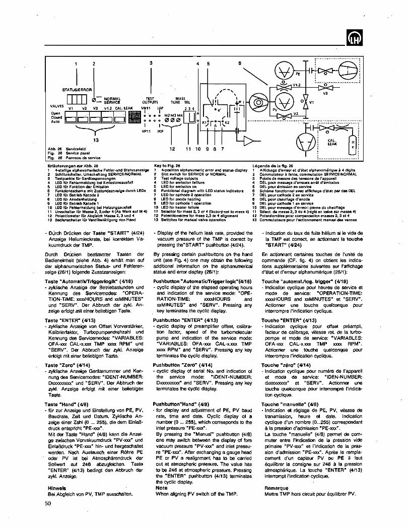
~------------------------~ ..........................
2 3 5 6 4
~ .. : · . · . · . · . · 0 : · . · . · .
Vl.2 :····0· .. ··········· .. ··: STATUS/ERROR , .... - ... v, [ill]
, , 0 - NORMAL TeST MASS I,
- SERVICE OUTPUTS TUNE SEL ! L--, ~ I 0 VALVES VI V2 V] VI.2 CAL. LEAK VN11 ItP 234 °e' ~lr'1
o V1
~?ID$DI.vt: IT0'~'04CP: '~r:l('2 I 11 .... ~ .......... .9 ....... ~ ........... :::::~:::s;:::::::: .. 13 I l::t>- 'CAL'
Abb. 26 Servlcefeld 12 11 10 9 8 7 j. LEAK ~ !. Fig. 26 Service panel FJg. 26 PQo/leau de service :" .................... :
Erlillterungen zur Abb. 28 1 4-stelllge alpha numerische Fehler·und Stetusanzelge 2 Schlll:.:schatler, UmSChaltung SERVICE/NORMAL 3 Testpunkle lilT GeriUespannungen 4 LED lOr Fehlermeldung bel Emissionsausfall 5 LeO lOr Funktlon der Emission 6 Funktlonsschema mil Zuslandsan:;zelge dUTch LEOs 7 LED IUr Betrleb Katoda 2 8 LED fllr Anodenheizung 9 LED fUr BatTleb Katoda 1 10 LED fUr Fehlermeldung bel Hel.::ungsausfall 11 Umschalter ftir Massa 2, 3,oder 4 (Ab Werk auf M 4) 12 Potentiometer IUr Abglelch Masse 2, 3 und 4 13 Bedlenschalter fUr Ventllbetitlgung von Hand
~ Durch Drucken der Taste "START" (4/24) Anzeige Heliumleckrate. bel korrektem Va~ kuumdruck der TMP.
Durch DrOcken bestimmter Tasten der Bedieneinheit (siehe Abb. 4) erMlt man auf der a1phanumerischen Status~ und Fehleran~ zeige (26/1) folgende Zusatzanzeigen:
Taste "AutomatlkITriggerloglk" (4I1S) - zyklische Anzeige der Betriebsstunden und
Kennung des Servicemodes: "OPERATION·TIME; =HOURS and ""MINUTES" und "SERV". Der Abbruch der zyk1. Anzeige erlolgt mit einer belieblgen Taste.
Taste "ENTER" (4113) - zyklische Anzeige von Offset Vorversta.-ker,
Kalibrierlaktor, Turbopumpendrehzahl und Kennung des Servicemodes: "VARIABLES: OFA-xxx CAL-x.xxx TMP xxxx RPM" und "SERV". Der Abbruch der zykl. Anzeige erlolgt mit einer befieblgen Taste.
Taste "Zero" (4114) - zyklische Anzeige Geratenummer und Ken
nung des Servicemodes: "IDENT-NUMBER: DXXlOOQOOO(" und "SERV". Der Abbruch der zykl. Anzeige erlolgt mit einer beliebigen Taste.
Taste "Hand" (4IS) - fUr zur Anzeige und Einsteflung von PE, PV,
Baudrate, Zeit und Datum. Zyklische Anzeige ainer Zahl (0 ... 255), die dem EinlaBdruck entspricht "PE-xxx". Mit der Taste "Hand" (4/S) kann die Anzeiga zwischen Vorvakuumdruck "PV-xxx" und EinlaBdruck "PE-xxx" hin- und hergeschattet werden. Nach Austausch einer ROhre PE oder PV ist bei Atmospharendruck der Sonwert auf 246 abzugleichen. Taste "'ENTER" (4/13) bedingt den Abbruch der zykl. Anzeige.
Hinwels BeLAbgleich von PV, TMP ausschalten.
50
Key to Fig. 26 1 4-posltlon alphanumeric error and status display 2 Slot SWitch lor SERVICE or NORMAL 3 Test voltage outputs 4 LED for emission falliure 5 LED for emissIon on 6 Funklional diagram with LEO status Indicators 7 LED for cathode 2 operallon 8 LED for anode healing 9 LeO lor cathode 1 operation 10 LEO lor heater failure 11 Selector for mass 2, 3 or 4 (Iactory-setto mass 4) 12 Potentiometers for mass 2,3 or 4 alignment 13 Switches for manual valve operation
Legende de la fig. 26 1 Al/lchage d'erreur et d'etat alphanumerlqua a 4 dlglls 2 Commutaleur a fente, commutation SERVICE/NORMAL 3 Points da mesure des tensions de l'appareH 4 DEL pour message d'erreuts arrit d'emlsslon 5 DEL pour emission an service 6 Schema loncl/onnel avec afflchage d'etat par des DEL 7 DEL pour cathode 2 an service 8 DEL pour chauffage d'anode 9 DEL pour cathode 1 en service 10 DEL pour message d'erreur: panne du chaulfage 11 Select. de masse 2, 3 ou 4 (regie en uslne sur masse 4) 12 Potentiometre pour compensation masses 2, 3 at 4 13 Commutateurs pour I'actlonnemanl manuel des vannes
- Display of the helium leak rate, provided the vacuum pressure of the TMP is correct by pressing the"START" pushbutton (4/24).
- Indication du taux de fuite haJj,um si Ie vide de la TMP est correct, en actionnant la touche ·START"' (4124)
By pressing certain pushbuttons on the hand unit (see Fig. 4) one may obtain the following additionat information on the alphanumerical status and error display (26/1):
Pushbutton" AutomaticlTrigger logic-(4118) - cyclic display 01 the elapsed operating hours
and indication of the service mode: "OPERATION· TIME; =HOURS and xxMINUTES" and "SEAV". Pressing any key terminates the cyclic display.
Pushbutton "ENTER" (4113) - cyclic display of preamplifier offset, catibra
tion factor, speed of the turbomolecular pump and indication of the service mode: "VARIABLES: OFA-xxx CAL-x.xxx TMP xxxx RPM" and "SERV". PreSSing any key terminates the cyclic display.
Pushbutton "Zero" (4114) - cyclic display 01 serial No. and indication of
the service mode: "IDENT-NUMBER: Dxxxxxxxxx" and "SERV". Pressing any key terminates the cyclic display.
Pushbutton"Hand" (4IS) • for display and adjustment of PE, PV baud
rate, time and date. Cyclic display of a number (0 ... 255), which corresponds to the inlet pressure "PE-xxx". By pressing the "Manual" pushbutton (4'S) one may switch between the display of fore vacuum pressure "PV·xxx" and inlet pressure "PE-xxx". After exchanging a gauge head PE or PV a realignment has to be' carried out at atmospheric pressure. The value has to be 246 at atmospheric pressure. Pressing the "ENTEW pushbutton (4/13) terminates the cyclic display. Note When atigning PV switch off the TMP.
En ac1ionnant certaines touches de I'unite de commande (CF. fig. 4) on obtient les indications supplemantaires -suivantes sur "affichage d'etat at d'erreur alphanumerique (26/1):
Touche "automat/log. trigger" (4I1S) - Indication cyclique pour heures de service et
moda de service: "OPERATION-TIME: xxxxHOURS and xxMINUTES" et "SERV". Actionner une touche quelconque pour interrompre "indication cycfique.
Touche "ENTER" (4113) - Indication cyclique pour offset preampli,
facteur de calibrags, vitesse rot de la turbopompa et mode de service: "VARIABLES: OFA·lOO( CAL-x.xxx TMP XXX)( RPM". Actionner una touche quelconque pour interrompre I'indication cyclique.
Touche "zero" (4114) - Indication cyclique pour numero de I'apparell
et mode de service: "IDEN-NUMBER: dxxxxxxxxx" et "SERV". Actionner une touche quelconque pour interrompre I'indication cyclique.
Touche "manuelle" (4IS) - Indication et reglage de PE, PV, vitesse de
transmission, heure et date. Indication cyclique d'un nombre (0 ... 255) correspondant a la pression d'admission "PE-xxx". La touche "manuelle" (4/8) permet de commuter entre I'indication de la pression vide primaire "PV-xxx" at t'indication de la pression d'admission "PE·xxx". Aprea Ie remplacemant d'un capteur PV ou PE i~ faut equilibrer la consigna sur 246 a la pression atmospMrique. La. touche "ENTER" (4/13) interrompt t'indication cyclique.
Remarque Mettre TMP hors circuit pour equitibrer PV.
~-------------------------Mit dar Taste "AutomatikITriggerlogik" (4118) beginnt nun Anzeige und Anderung von Baudrate, Datum und Zeit
Die Taste "ENTER" (4/13) bestatigt jeweils den angezeigten Wert und fQhrt zur nachsten DarsteUung. Es erscheint zunAchst: - "MODIFY VALUES OF BAUD, TIME AND
DATE" - AnschlieBend wird die Baudrate angezeigt:
-BAUD xxx",
Der angezeigte Wert "xxxx" kann mit den Werteingabetasten (4/6) und (4/19) verandert oder mit der Taste "Zero" (4/14) auf "9600" rOckgesetzt werden.
Die Taste "ENTER" (4113) bestatigt den angezeigten Wert und fOhrt zur Anzeige dar Uhrzeit "TIME". Nach ca. 1 s erscheinen die Stunden "H = xx". Die Stunden kOnnen mit den Werteingabetasten (4/6) und (4/19) VBrAndert oder mit der Taste "Zero" (4/14) auf "00" ruckgesetzt werden.
Die Taste "ENTER" (4113) bestatigt den an· gezeigten Wert und fUhrt zur Anzeige der Minute.
"M-xx".
Die Minuten kOnnen mit den Werteingabetasten (4/6) und (4/19) verandert oder mit der Taste "Zero'" (4/14) auf "00" rOckgesetzt werden.
Die Taste "ENTER" (4/13) bestatigt den angezeigten Wert und fOhrt zur Anzeige des Datums "DATE". Nach ca 1 s erscheint der eingestallt Tag "D-xx". Die Tage kennen mit den. Werteingabetasten (4/6) und (4119) verandert oder mit der Taste "Zero" (4/14) auf "01" rQckgesetzt werden.
Die Taste "ENTER" (4/13) bestatigt den angezeigten Wert und ffihrt zur Anzeige des Monats.
"M-xx".
Die Monate kennan mit den Werteingabetasten (4/6) und (4/19) verandert oder mit der Taste "Zera" (4/14) auf "01" rOckgesetzt werden.
Die Taste "ENTER" (4/13) bestatlgt den angezeigten Wert und Whrt zur Anzeige des Jahres.
"J=xx".
Die Jahre' kennen mit den Werteingabetasten (4/6) und (4/19) verandert oder mit der Taste "Zero" (4/14) auf "90" rUckgesetzt werden.
Die Taste "ENTER" (4/13) bestatigt den angezeigten Wert und zeigt nochmals die gewahlten Einsteilungen von Baudrate, Zeit und Datum.
Dar Ul 100 PLUS kann nach Einstellung des "SERVICE 1 NORMAL "-Schlitzschafters (25/2) in Stellung "NORMAL" und einer anschlieBenden autom. Initialisierungsphase aile Funktionen wieder ausfuhren.
Hinwels Die Ventilstellung "OFFEN" wird jeweils durch eine leuchtende LEO angezeigt
Pressing the "Automaticltrigger logic" pushbutton. (4/18) starts tha display and modification procass for baud rate, date and time.
Pressing "ENTER" (4/13) acknowledges the displayed value and_ leads to the next display. Displayed first is: - "MODIFY VALUES OF BAUD, TIME AND
DATE" - Next the baud rate is displayed:
"BAUD xxx".
The displayed value "xxxx" may be changed by operating the parameter entry push buttons (4/6) and (4119) or it can be reset to "9600" by pressing the "Zero" button (4/14).
Pressing "ENTER" (4/13) acknowledges the displayed value leading to the display of "TIME". After 1 s approx. the hours "H = xx" are indicated. The hours value may be changed by operating the parameter entry pushbuttons (4/6) and (4119) or it can be reset to "00" by pressing the "Zero" pushbutton (4114).
Pressing "ENTER" (4/13) acknowledges the displayed value leading to the display of the minutes.
"M-xx".
The minutes value may be changed by operating the parameter entry pushbuttons (4/6) and (4/19) or it can be reset to "00" by press· ing the "Zero" pushbutton (4/14).
Pressing "ENTER" (4/13) acknowledges the displayed value leading to the display of the "DATE". After 1 S approx. the date "D=xx" is irrjicated. The date may be changed byop· erating the parameter entry push buttons (4/6) and (4/19) or it can be reset to "01" by pressing the "Zero" pushbutton (4/14).
Pressing "ENTER" (4/13) acknowledges the displayed value leading to the display of the month:
"M-xx".
The month may be changed by operating the parameter entry pushbuttons (4/6) and (4/19) or it can be reset to "01" by pressing the "Zero" pushbutton (4/14).
Pressing "ENTER" (4/13) acknowledges the displayed value leading to the display of the year.
·"J=xx".
The year may be changed by operating the parameter entry pushbuttons (4/6) and (4/19) or it can be reset to "90" by prassing the "Zero" pushbutton (4114).
Pressing "ENTER" acknowledges the displayed value and in this case the selected entries of baud rate, time and date are displayed once more.
After setting the "SERVICE 1 NORMAL" slotted switch (25/2) back to the "NORMAL" position of the UL 100 PLUS regains all its functions again after a brief initialization phase which is run automatically.
Note The valve position "OPEN" is indicated by an illuminated LEO.
La touche "autom.!1og. trigger" (4/18) permet alors I'indication at Ie r8glage de la vitesse de transmission, de la date et de I'heure.
Actionner la touche "ENTER" (4/13) pour confirmer cheque valeur at passer a la suivants. On obtient d'abord: - "MODIFY VALUES OF BAUD, TIME AND
DATE" - ensuite, la vitesse de transmission est indi-
quee: "BAUD xxx".
La valeur indiquee "xxxx" peut etre modifiee avec las touches d'entree de valeur (4/6) et (4/19) au initialisee sur "9600" avec la touche "zero" (4114).
Actionner la touche "ENTER" (4/13) pour confirmer la valeur et passer a ceUe de I'heure "TIME". Les heures apparaissent env. 1 s apras "H =xx". Elias sa reglent avec les touches d'entree de valeur (4/6) et (4/19) et sont remises a "DO., avec la touche "zero" (4114).
Actionner la touche "ENTER" (4/13) pour confirmer la valeur at passer aux minutes.
Elias se reglent avec las touches d'entree de valeur (4/6) et (4119) et sont t:emisas a "00" avec la touche "zero" (4/14).
Actionner la touche "ENTER" (4/13) pour confirmer la valeur et passar a I'indication de la "DATE"-. Le jour "O-xx" apparait env. 1 s apres. II se regIe avec les touches d'entree de valeur (4/6) et (4/19) at prend la valeur "01" avec la touche "zero" (4/14).
Actionner la touche "ENTER" (4/13) pour con firmer la valeur at passer a celie du ·mois.
"M-xx"
II sa regie avec las touches d'entree de valeur (4/6) et (4/19) at prend la valeur "01" avac la touche "zero" (4/14).
Actionner la touche "ENTER" (4/13) pour con~ firmer la valeur et passer a celie de I'annee.
"J-xx"
Elle se regie· avec las touches d'entree de valeur (4/6) at .(4/19) et prend la valeur "90" avec la touche "zero" (4/14).
Actionner la touche "ENTER" {4/13} pour confirmer 18 valeur et revoir les reglages de la vitesse de transmiSSion, de I'heure et de la date.
UL 100 PLUS peut de nouveau executer toutes les fonctions, apres Ie reglage du commutateur a fente "SERVICE I NORMAL" (25/2) sur "NORMAL" at la phase d'initialisation automatique qui suit
Remarque La position de robinet "OUVERTE" est indiquae a chaque fois par une DEL allumee.
51
-----______ --'--,--il Die Bedienscha!ter (26/13) mOssen bairn Einklappen der Elektronik·Einheit (2513) immer in Stellung .. AUTOMATIK" geschaltet werden.
Auf der alphanumerischen Status- und Fehleranzeige (26/1) wire! dam Servicepersonal bei einem Fehler im UL 100 PLUS ein Fehlercode gemeldet, der die Wartung bzw. Instandsetzung wesentlich vereinfachl
~usatzlich lassen sich aile wichtigen Geratespannungen an den Mef3stellen "TEST OUTPUTS" (26/3) prillen.
Ole Bezelchnung der Prii1buchsen (26/3) und Ihrs Bedeutung 1m Elnzelnen:
VN11 neg. Versorgungsspannun9, stabilisiert = -11,5 bis -15,5 V
VP2 Versorgungsspannung, unstabilisiert = 20,0 bis 30 V
CP interner Takt fOr MS-Versorgung f • 68 kHz ±5 % (5 V's)
lAP Istwert-Anoden-Potential 4,3 bis 4,9 V (Xl 00) fOr Masse 4
VP11 pas. Versorgungsspannung, stabilislert ·11,5 bis 15,5 V
V02 Bezugsmasse fOr PrOfpotentiaie
ISP Istwert-Suppressor-Potential 3,0 bis 3,4 V (x100)
IKP Istwert-Katoden-Potential 3,5 bis 4,1 V (x100) fOr Masse 4
2.7.1 Statusanzeige Die Bedeutung der Statusmeldungan:
"INIT" Die Anzeige "INIT" erscheint nach dem Einschalten des UL 100 PLUS wah rend dar Injtialislerungsphase fOr 9inige Sekunden.
"Laufschrlft" Nach dam Einschalten des UL 100 PLUS arscheint in der Statusanzeige (26/1) einmal durchlaufend:
UL 100 PLUS VERSION·2.0 DATE-xx.xx.xx TIME-xx.xx.xx.
"ACCL" Accelerate, die Mikroprozessorsteuerung war· tet nach der Initialisierung auf das Unlerschreiten das Vorvakuumdrucks unter 0,1 mbar sowie auf das Ende des Hochlaufs dar Turbomolekularpumpe (63.000 min").
"VAC" und "SNIFF" Der Ul 100 PLUS verlOgt grundsatzlich Ober zwei Betriebsarten, die Vakuumlecksuche "VAC" (siehe Abschnitt 2.4) und die SchnOffellecksucha "SNIF" (sieha Abschnitt 2.4.8).
Der UL 100 PLUS zeigt die gegebenanfalls Ober den SchlOssel Nr. 6 gewahlte Betriebsart wAhrend des Geratehochlaufes an. Wird der SchlOssel Nr. 6 nicht aktiv, geht der Leeksucher automatisch in den Vakuumlecksuchbetrieb.
Hlnwels Die einmal gewahlte Betriebsart "VAC" oder "SNIFF" bleibt nach dam Ausschalten des Garales emalten.
52
Whenever the electronics unit (2513) is folded back in, the switches (26/13) must always sw"ched to "AUTOMATIC".
On the alphanumeric status and error display (26/1), an error code is displayed in the event of an error in the UL '00 PLUS; this considerably simplifies repairs or servicing.
In addition, all major voltages within the unit can be checked at the "TEST OUTPUTS" (26/3).
Designation of the Test Sockets (26/3) and Their FUnction:
VN11 Neg. supply voltage, regulated :::I -11.5 to -15.5 V
VP2 Supply voltage, unregulated :II 20.0 to 30 V
CP Internal clock for mass spectrometer supply f=68 kHz ±5 % (5 Vpp)
lAP Anode potential, actual value 4.3 to 4.9 V (xl00) for mass 4
VP11 Pas. supply voltage, regulated =".5 to 15.5 V
V02 Reference ground for the test poten-tials
ISP Suppressor potential, actual value 3.0 to 3.4 V (Xl00)
IKP Cathode potential actual value 3.5 to 4.1 V (x100) for mass 4
2.7.1 Status Indication The meanings· of the ~tus indications are:
"INIT" After switching on the UL 100 PLUS, "INIT" is displayed for several seconds during the initialization phase.
"Running display" After switching on the UL 100 PLUS the status display (2611) displays once the following one after the other:
UL 100 PLUS VERSION-2.0 OATE·xx.xx.xx TIME-xx.xx.xx.
"ACCL" Accelerate: after initialization the microprocessor control waits for the forevacuum pressure to drop below 0.1 mbar and for the turbopump to finish running-up (63,000 rpm).
"VAC" and "SNIFF" The UL 100 PLUS has been provided with two basic operating modes, vacuum leak detection "VAC" (see section 2.4) and sniffer leak detection "SNIF" (see section 2.4.8).
During rup-up the UL 100 PLUS displays any possibly selected operating mode entered with ~ey No.6. If key No. 6 is not used, the leak detector automatically enters the vacuum leak detection mode.
Note The once selected operating mode "VAC" or "SNIFF" remains stored -in the memory even after switching off.
Les commutateurs (26/13) doivent toujours etre reghas sur "AUTOMATIQUE" lors de la fermeture de t'unite electronique (2513).
Un affichage d'erreur alphanumerique (26/1) facilita enormement les travaux de maintenance ou de remise en Stat en signalant les erreurs du detecteur UL 100 PLUS au moyen d'un code.
II est egalement possible de controler toutes les tensions importantes de I'appareil sur les points de mesure "TEST OUTPUTS" (26/3).
Designation at signification des dlverses fiches (2613) femelles de controle:
VN11 Tension d'alimantation neg. stabilisee "" -11,58 -15,5 V
VP2 Tension d'alimentation non stabilises = 20,0 8 30 V
CP Horlage interne pour l'a1imentation du spectrometre de masse f "" 68 kHz ±5 % (5 Vpp)
lAP Valeur effective du potentiel d'anode 4,3 a 4,9 v (X100) pour masse 4
VP11 Tension d'alimentation pas., stabilises "" 11,5 a 15,5 V
V02 Masse de reference pour potentiels de controle
ISP Valeur effective du potentiel de sup-presseur 3,0 a 3,4 V (x100)
IKP Valeur effective du potential de cat-hade 3,5 _a. 4; 1 V (x100) pour masse 4
2.7.1 Indication d~etats Signification des divers messages d'etat:
"INIT" "INIT" est indique pendant quelques secondes, apres la mise en circuit de UL , 00 PLUS, pen· dant la montee en regime.
"Indication couranle" Apres la mise en Circuit de UL 100 PLUS, I'indication suivante se deroule sur I'affichage d'etat (2611):
UL 100 PLUS VERSION·2.0 DATE-xx.xx.xx TIME-xx.xx.xx.
"ACCL" Accelerate, spras I'initialisation la commande par microprocesseur attend que la pression primair'EI tombe en dessous de 0,1 mbar et la fin de la montee en regime de la pompa turbornoleculaire (63.000 tlmin).
"VAC" and "SNIFF" UL 100 PLUS dispose de deux modes prin· cipaux pour la detection de fuite, Ie mode vide "VAC" (CF. section 2.4) et Ie mode -renifl~ment "SNIF" (CF. section 2.4.8).
UL 100 PLUS indique, pendant la montee en regime, Ie mode de detection eventuel1ement choisi avec la cle no. 6. Si cette cle n'est pas active, UL 100 PLUS passe automatiquement en mode detection sous vide.
Remarque Le mode de detection choisi, "VAC" ou "SNIF" est conserve en memoire lorsque I'appareil est mis hers circuit
~------------------~-----"STBY" Stand-By, Lecksuch-Bereitschaftsmeldung des UL 100 PLUS: nach erfolgreicher Inbe~ triehnahme, nach Verlassen des LecksuchstaIus "MEAS" durch kurzes «2 s) Betatigen der Taste "STOP I VENT" und nach behebbarem Fehlerzustand. Die Ventils V1 und V3 sind geschlossen, V2 ist geOffnet Die Turbomolekularpumpe 18uft mit (63.000 min-1).
"EVAC" erscheint n8ch BetAtigsn der Taste "START" (4/,24), bei vorangegangenem Lecksuchslatus Stand-By ("STBY") oder Fluten ("VENT").
Die Ventila V2 und V3 sind geschlossen, V, ist geOffnet.
Wird im Teilstrombetrieb mit angeschlosS8-nem Teilstromventil gearbeitet, sind V1, V1.2 und V3 geschlossen und V2 'und Vext geoffnet
"MEAS" erscheint n8ch dam Evakuieren ("EVAC"), wenn dar Druck ain Einlal3 unter 0,2 mbar oder im Teilstrombetrieb unter 100 mbar gesunken ist und die Leckrate auf der Bedienainhait angezeigt wird.
Die Ventile Vl und V2 sind geOffnet, V3 ist geschlossen.
Wird im Teilstrombetrieb mit angeschlosse· nem Teilstromventil gearbeitet, sind bei einem Einlaf3-Druck von 100 mbar > PE > 0,2 mbar Vl und' V3 geschlossen und V2, Vl.2 und Vext ge6ffnel. Bei einem Einlaf3-Druck von PE < 0,2 mbar sind Vl, V2 und Vext ge6ffnet, V3 und Vl.2 sind geschlossen.
"VENT" erscheint nach Fluten des EinlaBbereiches und Verlassen des Lecksuchstatus "MEAS" durch langes (> 2 5) Betatigen der Taste "STOP! VENT" (4/2).
Die Ventile V2 und V3 sind ge6ffnet, Vl. Vl.2 und Vext ist geschlossen.
"CAL" Cal erscheint beim kalibrieren.
2.7.2 Fehlermeldung Die Bedeutung der Fehlermeldungen im ainzelnen:
"EROO" Erscheint im Servicafeld in der Statusanzeige die Anzeige "ERDO", liegt ein Systemfehler var. In der Statusanzeige erscheint als st.!lndig durchlaufender Text:
ERDD * CODE-xx * LlNE·xxxxx xx Zahlenwert von 1 bis 40 xxxxx Zahlenwert von 1 bis 32 767
Durch einen Neustart kann es moglich sein, daB sich dar Systemfehler automatisch be· seitigt. Sollte der Systemfehler wiederholt auftreten, ist unbedingt der Service zu benachrichtigen.
OSTBY· Standby: this indicates that the UL 100 PLUS is ready for leak detection: this occurs after successful run-up or after having left the leak detection status "MEAS" by operating the pushbutton "STOP! VENT" for less than 2 s and after a rectified fault Valves Vl and V3 are closed, V2 is open. The turbo molecular pump is running (63.000 rpm).
"EVAC" is displayed after operating the "START" pushbutton (4/24) after having been in the standby ("STBY") or vent ("VENT") mode.
Valves V2 ·and V3 are closed; valve Vl is open.
In the case of partial-flow operation with a connected partial-flow, valves Vl, Vl.2 and V3 are closed and V2 and Vext are open.
"MEAS" is displayed after evacuation ("EVAC"), if the pressure at the inlet ,has dropped below 0.2 mbar or, in the case of partiaHlow operation, below 100 mbar and the leak rate is indicated on the remote control unit
Valves V1 and V2 are open; V3 is closed.
In the case of partial-flow operation with a connected partial-flow valve and an inlet pressure of 100 mbar >PE> 0.2 mbar, V1 and V3 are closed and V2, V1.2 and Vext arl;! open. At an inlet pressure of Pi: < 0.2 mbar' V1, V2 and Vex\ are open, V3 and Vl.2 are closed.
"VENT" is displayed after venting the inlet area and leaving the leak detection status "MEAS" by operating the "STOP I VENT~ pushbutton (4/2) for more than 2 s.
Valves V2 and V3 are open, Vl, Vl.2 and Vext are also closed.
"CAL" Cal is displayed during calibration.
2.7.2 Error Messages The different error messages have the following meanings:
"EROO" If "EROO" is displayed on the status display on the service panel there is a system fault. The status displays continuously the following text:
EROO * CODE-xx * lINE·xxxxx xx Value from 1 to 40 xxxxx Value from 1 to 32 767
By restarting it may be possible that the system fault disappears automatically. Should the system fault appear repeatedly call the service.
OSTBY" Stand-By, UL 100 PLUS signale qu'll est prAt a detecter des fuiles. Ce mode est etabli apres une bonne mise en service, en sortant du mode detection nMEAS" en actionnant brievement « 2 s) la touche "STOP I VENT" et apras la correction d'un etat d'erreur. Les robinets Vl at V3 sont fermes, V2 est ouvert. La pompa turbomoleculaire lOume (63.000 T/min).
"EVAC" Apparait apres I'actionnement de la touche "START" (4/24), si I'appareil etait precede· ment en mode Stand-By rST8Y") au remise a I'air ("VENT").
Les robinets V2 at V3 sont fermes, Vl est ouvert.
En regime a flux partiel avec robinet flux partiel raccorde, VI, Vl.2 et V3 sont fermes et V2 at Vext sont ouverts.
"MEAS" Apprait apres I'evacuation ("EVAC"), lorsque la pression tombe en dessous de 0,2 mbar a I'admission au en regime flux partiel sous 100 mbar at que Ie taux de fuile est affiche sur I'unite de commande.
Les robinets Vl et V2 sont ouverts, V3 est ferms.
Lorsqu'on travaille en flux partiel avec robinet flux partiel raccords, pour une pression d'admissic;m de 100 mbar >PE > 0,2 mbar, Vl at V3 sont farmss at V2, Vl.2 at Vext sont ouverts. Pour une pression d'admission de Pe < 0,2 mbar, V1, V2 et Vext sont auverts, V3 et Vl.2 sont fermes.
"VENT" Apparait apres la remise a I'air de la zone d'admission et apras avoir quittB I'etat de detection "MEAS" en actionnant longtemps (> 2 s) la touche "STOP I VENT~ (4/2).
Les (obinets V2 at V3 sont ouverts, Vl. V1.2 et Vext sont fermes.
"CAL" CAL apparait pendant Ie calibrage.
2.7.2 Messages d'erreurs Les divers messages d'erreurs ont 1a significa· tion suivante:
"EROO" ee message apparait sur I'affichage d'etat du panneau de service en cas d'arreur du systeme. Le message suivant se deroule continuallament sur I'affichage:
EROO * CODE-xx * lINE-xxxxx xx Value from 1 to 40 xxxxx Value from 1 to 32 767
L'erreur du systeme peut eventuellement dis'paraitre automatiquement avec une nouvelle mise an circuit Si elle recommence il faut absolument consulter Ie S.A. V.
53
--------------------------~ "ER01" • Es wurde sin Milerer Vorvakuumdruck a1s 0,4 mbar festgestellt, z.B. verursacht durch sine" Lufteinbruch am PrOfling. Zurn Schutz der lonenquelle hat sich die MassenspektrometerVersorgung selbsttatig abgeschaltet (siehe unter "CONT").
"ER02" Es wurds sin Fadenbruch an der Thermov8CMeBstelie EinfaB {Pel festgestellt (Service ruten),
"ER03" Es wurds sin Fadenbruch an der ThermovacMeBstelle Vorvakuum (Pv) festgestellt (Service rufen).
"EROS" " WAhrend des Hochlaufes (" ACel Of) wird der Vorvakuumdruck von Pv < 0,1 mbar innerhafb 3 min nach Inbetriebnahme nicht erreicht Fehlerursachen kOnnen sain:
- das Pumpmodul fehlt - der Vorvakuumbereich einschUeBlich Vaku-
umkupplung entMlt ein grobes Leck - 'die Vorvakuumpumpe 1M nicht an oder
srreicht die Nenndrehzahl nicht - die Ventilsteuerung arbeitet fehlerhaft (siehe unler "CONT")
"ER06" " Die Drehzahl der TMP 50 liegt unterhalb 63 000 min-1 (siehe unter "CaNT").
"ER07" " Oer Offset des Elektrometerverstarkers ist kleiner 15 mV. (siehe unter CONT).
"ERoe" • Der Offset des Elektrometerverstarkers ist grOBe'r 90 mV (siehe unter CaNT). Normalerweise betragt der Offset ca. 50 mV
"ER09" Die lonenquelle ist defekt (Bruch beider Katoden) oder Fehler in der Massenspektrometer-Versorgung.
MERlO" Die Fehlermeldung "ER 10" erscheint, bei etnem Fehlar im batteriegepufferten Speicher. Die GrundeinsteHung wird durchgefOhrt.
Oiese Fehlermeldung wird nur in der Initialisierungsphase abwechselnd dutch "EA 10 1 INIT" angezeigt
"EA2l" • WAhrend des Hochlaufes (SNIF) wird der Einlal3druck (Pe) innerhalb von 2 min nach Inbetriebnahme nicht erreicht Fehlerursachen kOnnen sein: - VakuumanschluB zwischen EinlaBflansch
und SchnOffler undicht - SchnOffeUeitung undicht. - Schnuffelspitze defekt (siehe unter "CONT")
Nach Auftreten eines im StatuSlFehler-Display angezeigten Fehlers, wechselt die Anzeige periodisch zwischen der Fehlermeldung und letzter Statusanzeige. Dabei blinkt die FehlerIndikator lED (4/20).
• CaNT E~scheint nach Beseitigung des Fehlars im
54
MER01" • A vacuum pressure of more than 0.4 mbar has been detected, for example caused by an air inrush into the test object. For protection of the ion source the mass spectrometer supply has been automatically switched off (see "CaNT").
"ER02" A filament breakage has been detected at the Thennovac measurement point inlet (PEl (see below. "CaNT").
"ER03" A filament breakage has been detected at the Thennovac measurement point forev8Cuum (Pv) (Call service).
"EROS" " During run-up (" ACCl ") the forevacuum pressure of Pv < 0.1 mbar has nol been· reached within 3 min after being ready for operation. Either of the following faults may be the reason for this: - the pump module is missing - there is a coarse leak within the forevacuum
area including the vacuum coupling - the backing pump is not running or has not
reached its nominal speed - the valve control is faulty. (see "CaNT")
"ER06"· The speed of the TMP 50 turbo pump is below 63,000 rpm (see "CONT").
"ER07" " The offset of the high impedance input amplifier is below 15 mV (see "CONT").
"EROS" • The offset of the high impedance amplifier is higher than 90 mV (see "CONT"). Normally the offset is below 50 mV.
"ER09" The ion source is faulty (both cathodes broken) or there is a fault in the mass spectrometer supply.
MERlO" The error message ilEA 10" is displayed in the event of a fault in the battery backed-up memory. Default settings will then be used.
This error message is only displayed alternatinglyas "EA 10 1 INIT" during the initialization phase.
"ER2l" • During run~up (SNIF) the inlet pressure (PEl was not reached within 2 min. after switching on. This may be due to: - A leaky vacuum connection between inlet
flange and sniffer - A leaky sniffer line - A faulty sniffer tip (see "CaNT")
After a fault has been indicated by the status lerror display the display changes alternatingly between error message and the last indicated status display. During this time the error indicating LEO (4/20) flashes.
·CONT If after removal of the fault the status display
HER01" • Detection d'une pression primaire superieure a 0,4 mbar provoquee p.ex. par une entree d'air dans I'objet a tester. L'aHmentation du spectrom8tre de masse a eta coupee 'aulomatiquement pour proteger la source d'lons (voir OCONTO).
"ER02" Signale une rupture de filament au point de mesure admission (Pe) de Thermovac (ct. "CONT").
"ER03" Signale une rupture de filament au paint de mesure previde de Thermovac (Pv) (Appefer Ie S.A.V.).
"EROS" " La pression primaire Pv < 0,1 mbar n'est pas atteinte pendant les 3 min suivant la mise en service et pendant la mantee en regime (" ACCl "). Les causes peuvent litre les suivantes: - Ie module pompe manque - fuite grassiers dans la zone previde compre-
nant I'accouplement a. vide_ ~ la pompe primaire ne demarre pas au n'at-
teint pas sa vitesse nominale - fa commande des robinets 'travaille mal. (voir "CaNT")
"EROS" • La vitesse de TMP 50 est inferieure a 63.000 t min" (voir "CONT").
"ER07" " l'offset de l'ampU electrometrique est-infsrieur a. 15 mV. (Cf. sous CONT).
"EROS"· L'offset de I'ampli electrometrique est superieur a 90 mV (Cf. sous CONT). Normalement I'offset est d'env. 50 mV.
"ER09" La source d'ions est defectueuse (rupture des deux cathodes) au defaut dans f'alimentation du spectromelre de masse.
"ER10" Signale une erreur dans la memoire tampon alimentee par pile. Le reglage par defaut est alors adopts.
Ce message d'erreur n'est indiqu8 que pendant la phase d'initialisation, dans I'alternance "EA 10 1 INIT".
"EA2l" • Pendant la mantee en regime (SNIF), la pression d'admission (PE) n'est pas. attaints pendant les 2 min apres la mise en circuit. Causes probables: - Fuite au raccord vide entre la bride d'aclmis-
sian et Ie renifleur. - Fuite de la conduite du renifleur. - Buse du renifleur defectueuse. (voir "CaNT")
Apres I'indication d'un defaut dans I'affichaga d'etat/d'erreur, I'affichage commute periodiquement entre message d'erreur et la derniere indication d'etat La DEL d'indication d'erreur (4/20) clignote en meme temps.
"CaNT Apres la correction d'une erreur, si I'affichage
mm ________ ~----------------Status-Display die Meldung "CONT" 1m Wechsel mit der letzten 'Fehlermeldung, so kann der UL 100 PLUS durch ein- oder zweimaliges kurzes Beta-ligen der Taste "START" (4/24) 2um Weiterarbeiten gebracht werden. Anschliel3end befindat sich der UL 100 PLUS nach ggf. notigem Hochlauf im Stand-ByLecksuchmodus ("STBY").
2.7.3 Abgleich der Massenpositlon
Urn die maximale Empfindlichkeit und Slabilit8.t zu ,erreichen, muB das Massenspektrometer des' 'UL 100 PLUS auf die richtige Massenposition abgeglichen werden.
Der UL 100 PLUS wird werksseitig auf M2 und M4 abgeglichen und eingestellt auf Masse 4 ausgeliefert.
Ein Abgleich ist nur fOr Masse 3 notwendig, fOr Masse 2 und 4 sollte der Abgleich bel der Kalibrierung OberprOft werden ( Abschnitl2.6).
Der Abgleich kann nur durchgefOhrt werden, wenn das entsprechende Gas eingelassen wird. FOr Masse 2 und 3 ist es notwendig, ein H2-Testleck (zum Beispiel TL 4 - 6, Kat- Nr. 155 80) mit Wasserstoff-Druckgasflasche am EinlaB des Lecksuchers anzuschlieBen. Fur Masse 4 kann ein extemes Heliumtestleck oder (falls vorhanden) das interne Test/eck verwendet werden.
Der Abgleich erfolgt fUr aile Massen wie folgt:
- Testleck am EinlaB anschlie/3en und Taste "START" (4/24) drOcken, um in den MEAS-Zustand zu gelangen.
- Umschalter (26/") am Servicefeld auf gewOnschte Masse steiten.
- Potentiometer (26112) far die gewOnschte Masse mil Schraubendreher so einstellen, daB maxi'male Anzeige erscheint (die Anzeige muB dann bel Verstellung des Potis in beiden Richtungen kleiner werden!).
- AnschlieBend Testleck schliel3en und OberprOfen, daB die Anzeige zUrUckgeht (es dart bei Masse 2 und 3 eine Restanzeige aufgrund des relativ hohen natOrlichen Untergrundes bzw. Partialdruckes bleiben, bei Masse 4 muB die Null-Indikator LED (4/21) leuchten).
indicates "CONT" alternating with the last status indication, the UL 100 PLUS can be brought back into the normal operating mode by briefly pressing the "START" pushbutton (4/24) once or twice. The UL 100 PLUS will then revert to the standby mode ("STBY") after run-up if required.
2.7.3 Alignment of Mass Position
In order to obtain maximum sensitivity and stability the mass spectrometer within the UL 100 PLUS must be correctly aligned.
The UL 100 PLUS is factory-aligned to masses M2 and M4 and supplied adjusted to mass 4.
Alignment for mass 3 may be neccessary. For masses 2 and 4 alignment should be checked during calibration (see Section 2.6).
The alignment procedure can only be carried out by letting the relevant test gas into the' UL 100 PLUS. For masses 2 and 3 it is reqiured to connect a H2 - calibrated leak (for example TL 4-6, Cat No. 155 80) with a pressurized hydrogen reservoir to the leak detector inlet For mass 4, use either the internal calibrated leak of the UL 100 PLUS or, if available an external helium calibrated leak.
The alignment process is the same for all masses and is as follows:
- Connect calibrated leak to the inlet and operate "START" pushbutton (4/24) so that the UL 100 PLUS is set to· the MEAS mode.
- Set switch (26/11) on the seNice panel to the desired mass.
- Use a screwdriver to operate the potentiometer (26/12) for the required mass. Turn the potentiometer until a maximum indication is reached, I.e. the indication will drop in both directions of the potentiometer.
- Then close the calibrated leak and make sure that the indication drops. In the case of masses 2 and 3, a small residual indication may remain due to the relatively high natural background resp. partial pressure: in the case of mass 4, Zero indicating LED (4/21) must come on.
d'etat indique alternativement "CONT" et Ie dernier message d'erreur, c'est qu'il est possible de continuer Ie travail avec UL 100 PLUS en appuyant une au deux 10is brievement sur la touche "START" (4/24). Ul '00 PLUS sa retrouve ensuite, apres une evsntuelle mantee en regime, dans Ie mode detection Stand-By ("STBY").
2.7.3 Compensation de la pOSition de masse
Pour obtenir la sensibilite et la stabilite maximales, Ie spectrometre de masse de UL 100 PLUS doit etre compense sur la position de masse correcte.
UL 100 PLUS est equilibre en usine sur M2 at M4 et regie sur masse 4.
Une compensation n'est necessairEl que pour la masse 3, celie des masses 2 et 4 devrait etre verifiee lars du calibrage (Cf. section 2.6).
La compensation ne peut EWe executes que lorsque Ie gaz correspondant penetre dans UL 100 PLUS. Pour les masses 2 et 3, iI faut raecorder une fuite calibree H2 (p.ex. TL 4 - 6, ref. 155 80) a I'admission du detecteur. Pour la masse 4 on peut utiliser soit une fuite helium calibree externe au (sl disponible) la fuite calibree interne.
La compensation se fait de la facon suivante pour loutes les masses:
- Aaccorder la fuite calibrea a I'admission at enfoncer la touche "START" (4/24) pour parvenir dans I'etat MEAS.
- Placer Ie seiecteur (26/11) du panneau de service sur la masse desiree.
- Regier Ie potentiometre (26/12) correspondant a la masse choisie avec un tournavis sur I'affichaga maximal (tout dereglage du potentiometre diminue alors la valeur afficMe!).
- Fermer ensuile la fuite calibree at verifier que I'affichage diminue (pour les masses 2 at 3 un afflchage residuel peut rester en raison d'un fond naturel du d'une pression partielle relativement importants, pour la maslj:e 4 la DEL 0 (4/21) daft s'allumer).
55
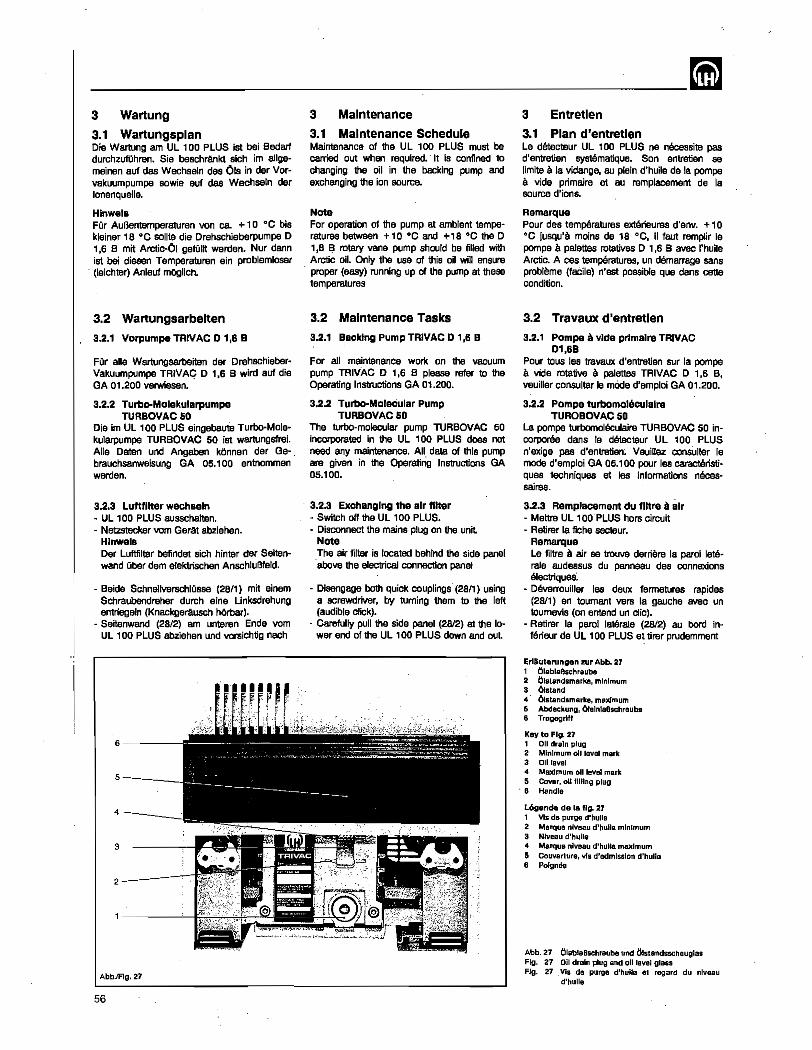
3 Wartung
3.1 Wartungsplan Die Wartung am UL '00 PLUS ist bel BOOarf durchzufUhren. Sie beschrtinkt sich im a1lgemeinen auf das Wachseln des Ols in der Vcrvakuumpumpe sowie auf das Wechseln der lonenquelle.
Hinwels FOr Aul3entemperaturen von ca. + 1 0 °C bis kleiner 18°C sollte die Drehschieberpumpe 0 1.6 8 mit Arctic-OJ gefOllt werden. Nur dann ist bei diesen Temperaturen ein problemloser (Ieichter) Anlauf m()glich.
3.2 Wartungsarbelten
3.2.1 Vorpumpe TRIVAC 0 1.6 B
FOr aile Wartungsarbeiten der DrehschieberVakuumpumpe TRIVAC 0 1.6 B wird auf die GA 01.200 verwiesen •.
3.2.2 Turbo-Molekularpumpe TURBOVAC50
Die im UL 100 PLUS eingebaule Turbo·Molekularpumpe TURBOVAC 50 ist wartungsfrei. Aile Daten und Angaben kOnnen der Gebrauchsanweisung GA 05.100 entnommen werden.
3.2.3 Luttfllter wechseln - UL 100 PLUS ausschalten. - Netzstecker vern Ger4t abziehen.
Hlnwels Der Luftfilter befindat sich hinter der Seitanwand uber dem eleklrischen AnschluBfeld.
- Beide Schnellverschlusse (28/1) mit einem Schraubendreher durch eine Unksdrehung entriegeln (Knackgerausch hOmar).
- Seitenwand (28/2) am unteren Ende yom UL 100 PLUS abziehen und vorsichtig nach
6----
5-___ _
4_-,-__
2-----:
AbblFlg, 27
56
3 Maintenance
3.1 Maintenance .Schedule Maintenance of the UL 100 PLUS must be carried out when required. It is confined to changing the oil in the backing pump and exchanging the ion source.
Note For operation of the pump at ambient temperatures between +10 °0 and +18 °0 the D 1,6 B rotary vane pump should be filled with Arctic oil. Only the use of this oil will ensure proper (easy) running up of the pump at these temperatures
3.2 Maintenance Tasks
3.2.1 Backing Pump TRIVAC D 1,6 B
For all maintenance work on the vacuum pump TRIVAC 0 1,6 B please refer to the Operating Instructions GA 01.200.
3.2.2 Turbo-MoleCular Pump TURBOVAC50
The turbo·molecular pump TURBOVAC 50 incorporated in the UL 100 PLUS does not need any maintenance. All data of this pump are given in the Operating Instructions GA 05.100.
3.2.3 Exchanging the air fitter • Switch off the UL 100 PLUS. - Disconnect the mains plug on the unit.
Note The air filter is located behind the side panel above the electrical connection panel
- Disengage both quick couplings' (28/1) using a screwdriver, by turning them to the left (audible click).
- Carefully pun the side panel (2812) at the lower end of the UL 100 PLUS down and out.
3 Entretlen
3.1 Plan d'entretlen Le detecteur UL 100 PLUS ne neC8Ssite pas d'entretien systematique. Son entretien se limite a la vidange, au plein d'huile de la pompe a vide primaire at au remplacement de la source d'ions.
Ramarque Pour des temperatures extarieures d'env. + 10 °C jusqu'a mains de 18°C, i1 faut remplir la pompe a palettes rotatives 0 1,6 B avec I'huile Arctic. A cas temperatures, un demarrage sans problema (faCile) n'est possible que dans cette condition.
3.2 Travaux d'entretlen
3.2.1 Pompa a vide prlmalre TRIVAC 01,6B
Pour tous las travaux d'entretien sur la pompa Ii vide rotative Ii palettes TRIVAC 0 1,6 B. veuiller consulter Ie mOde d'emploi GA 01.200.
3.2.2 Pompa turbomoleculalre TUROBOVAC 50
La pompe turbomoleculaire TURBOVAC 50 incorporee dans Ie detecteur UL 100 PLUS n'exige pas d'entretien~ Veuillez consulter Ie mode d'emploi GA 05.100 pour las caracteristj· quas techniques at las informations nacessaires.
3.2.3 Remplacement du flltre a air - Mettre UL 100'PLUS hors circuit - Retirer la fiche secteur.
Remarque Le filtre a air sa trouve derriere la paroi laterale audessus du panneau des connexions electriques:
- Deverrouiller las deux fermetures rapidas (2B/1) en toumant vers la gauche avec un toumevis (on entend un clic).
- Retirer la paroi laterale (2812) au bard interieur de UL 100 PLUS et firer prudemment
Erlliuterungen zur Abb. 27 , OlablaBschraubo 2 01standsmarka, minimum 3 01sland 4 Olslandsmarks, max/mum 5 Abdeckung, OralnlaBschrauba 8 Tragegrllf
Key to FIg. 27 1 011 draIn plug 2 MinImum 011 level mark 3 011 level 4 Maximum 011 level mark 5 Cover, olllllling plug
. 8 Handle
Legends de 18 Ilg. 27 1 Vis de purge d'hulle 2 Marque nlV88u d'huile minimum 3 Nlveau d'hulle 4 Marque nlva8u d'hulle maximum 5 Couvarture, vis d'sdmlsslon d'huile 6 Poignee
Abb.27 ClablaBschraube und Olstandsschauglas Fig. 27 Oll drain plug and 011 level glass Fig. 27 Vis de purge d'huile al regard du nlveau
d'huHe
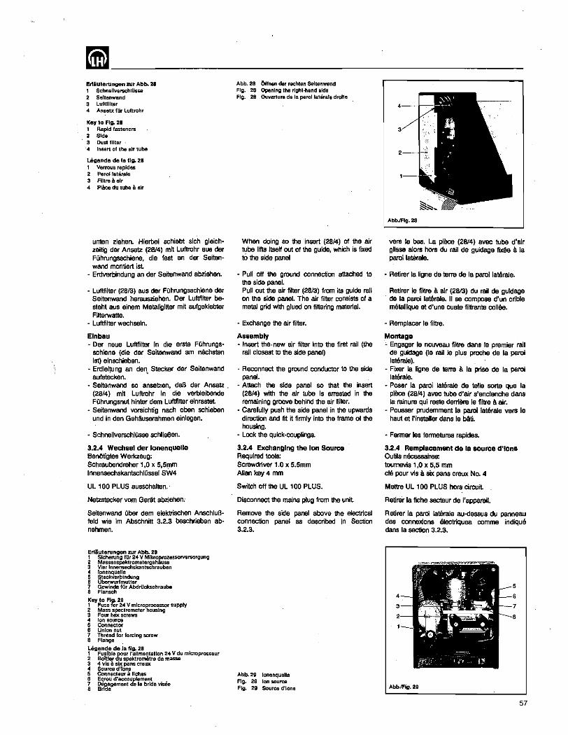
mm ________________________ __ El1iuterungen zur Abb. 28 , SchnellverschlUssa 2 Seltenwand 3 Luftfllter " Anset:;: fOr Luflrohr
Key to FIg. 28 1 Rapid fasteners 2 Side 3 Dust filter· " Insert of the air tube
Legende de Ie fig. 28 1 Verrous rapldes 2 Parol laterale 3 Filtre a air " Piece du tube a air
unten ziehen. Hierbei schiebt srch gleichzeitig dar Ansatz (2B14) mit Luftrohr aus dar FOhrungsschiene, die fest an dar Saitanwand montiert ist.
- Erdverbindung an dar Seitenwand abziehen.
- Luftfilter (2813) aus dar FOhrungsschiene dar Seitenwand herausziehen. Dar Luftfilter besteht aus einem MetaJlgitter mit aufgeklebter Filterwatte.
- Luftfitter wechseln.
Elnbau - Dar neue Luftfilter in die srate FQhrungs
sehiens (die dar Seitenwand am n6chsten ist) einschieben.
- Erdleitung an den Stecker dar Seitenwand aufstBcken. •
- Seitenwand so ansetzen, daB dar Ansatz . (28/4) mit Luftrohr in die verbleibende FOhrungsnut hinter dem Luftfilter einrastel
- Seitenwand vorsichtig nach oben schieben und in den Gehauserahmen einlegen.
- SchnellverschlOsse schlisBen.
3.2.4 Wechsel der lonenquelle Benotigtes Werkzeug: Schraubendreher 1,0 x 5,5r:nm InnensechskantschlOssel SW4
UL 100 PLUS ausschalten.
Netzstecker vom Gerat abziehen:
Seitenwand Ober dem elektrischen AnschluBreid wie im Abschnitt 3.2.3 beschrieben abnehmen.
Erlauterungen zur Abb. 29 ~ ~;~:!~~~~[,~~~t~::~E~$&zessorversorgung 3 Vier Innensechskantschrauben 4 lonenquelle 5 SlacleVerblndung e Oberwurlmutlar 7 Gewinde fllr Abdrllckschrauba e Flensch
~ey ~~s:lror2:4 V microprocessor supply 2 Mass spectrometer housing 3 Four hex screws 4 Ion source 5 Connector 6 Union nut 7 Thread for forcing screw 8 Flange Lagende de la tlg. 29
~ ~~W:::~ ru~~::~:!'~~~~!~~ ~~~u mlcroprosseur 3 4 vis a six pans craux 4 Source d'ions 5 Connecteur a fiches 6 Ecrou d'accouplemenl 7 Deaagement de Ie bride vises 8 BrICe
Abb.28 fmnen der rachlen Sellenwend Fig. 28 Opening the rlghl·hend side Fig. 28 Ouvorluro do la parollalerale droile
When doing so the insert (28/4) of the air tube lifts itself out of the guide, which is fIXed to the side panel
- Pull off the ground connection attached to the side panel. Pull out the air filter (2813) from its guide rail on the side panel. The air fitter consists of a metal grid with glued on filtering material.
- Exchange the air filter.
Assembly - Insert the·new air filter into the first rail (the
rail closest to the side panel)
- Reconnect the ground conductor to the side panel.
- Attach the side panel so that the insert (28/4) with the air tube is arrested in the remaining groove behind the air filter.
- Carefully push the side panel in the upwards direction and fit it firmly into the frame of the housing.
- Lock the quick-couplings.
3.2.4 Exchanging the Ion Source Required tools: Screwdriver 1.0 x 5.5mm Allan key 0 mm
Switch off the UL 100 PLUS.
Disconnect the mains plug from the unit
Remove the side panel above the electrical connection panel as described in Section 3.2.3.
Abb.29 lonenqualle Fig. 29 Ion source Fig. 29 Source d'ions
AbbJFlg.28
vers Ie bas. La pi9ce (28/4) avec tube d'air glisse alors hors du rail de guidage fi. a la paroi laterale.
• Retirer Is ligne de terre de la paroi laterale.
Retirer Ie filtre a alr (2813) du rail de guidage de la paroi laterale. II sa compose d'un crible metallique at d'une ouate filtrante colles.
~ Remplacer Ie filtre.
Montage ~ Engager Ie nouveau filtre dans Ie premier raJl
de guidage (Ie rail Ie plus proohe de la parol la"~e).
~ Fixer Ia ligne de terre a la prise de la paroi lateraJe.
• Poser la parol lateraJs de telle sarte que la pi9ce (28/4) avec tube d'alr s'enclenche dans ta- rainure qui reste derriere Is filtre a air.
~ Pousser prudemment la paroi laterale vera Ie haut at I'installer dans Ie bAti.
- Fermer les fermetures rapides.
3.2.4 Remplacement de la source d'lon8 Outils n9cessaires: toumevis 1,0 x 5,5 mm cle pour vis a six pans creux NO.4
Meltre UL 100 PLUS hors circuit
Retirer la fiche secteur de J'appareil.
Retirer la paroi laterale au-dessus du panneau des connexions electriques comme indiqu6 dans la section 3.2.3.
AbbJFig.29
57
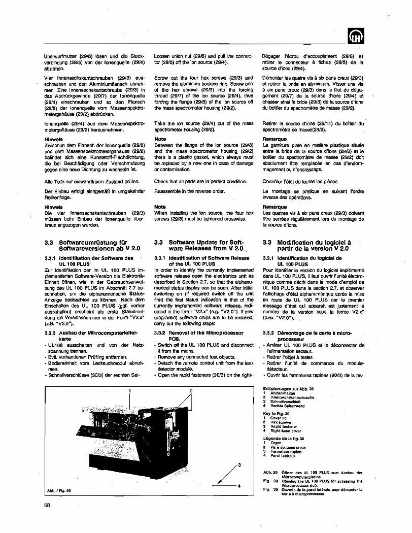
___________________________ mm Oberwurfmutter (29/6) IOsan und die Steckverb'lndung (29/5) von dar lonenquelle (29/4) abziehen.
Vier Innensechskantschrauben (29/3) 8USschrauben und den Aluminiumflansch abnehmen. Eine Innensechskantschrauba (2913) in das Abdruckgewinde (29n) dar lonenquelle (29/4) einschrauben und so den Flansch (29/8) dar lonenquelle vern MassenspektrometergeMuse (29/2), abdrOcken.
lonenquelle (2!)/4) aus dam Massanspektrometergehaus8 (29/2) herausnehmen.
Hlnwels Zwischen dam Flansch dar lonenquelle (29/8) und dam Massenspektrometergehause (29/2) befindet sich eine Kunststoff-Flachdichtung, die bei Beschadigung oder Verschmutzung gegen sine neue Dichtung zu wachseln ist.
Aile Teite auf einwandfreien Zustand prOfen.
Dar Einbau eriolgt sinngemAB in umgekehrter Reihenfotge.
Hlnwels Die vier Innensechskantschrauben (2913) mOssen beim Einbau der lonenquelle aberkreuz angezogen werden.
3.3 Softwareumriistung fiir Softwareverslonen ab V 2.0
3.3.1 Identl11katlon der Software des UL 100 PLUS
Zur Identifikation der im UL 100 PLUS implementierten Software-Version die ElektronikEinheit Offnen, wie in der Gebrauchsanweisung des UL 100 PLUS im Abschnftt 2.7 beschrieben, um die alphanumerische StatusAnzeige beobachten zu kOnnen. Nach dem Einschatten des UL 100 PLUS (ggf. vomer ausschalten) erscheint als erste Statusmeldung die Versionsnummer in der Form "V2.x" (z.B. "V2.0").
3.3.2 Ausbau der Mlkrocomputerlelterkane
- UL 100 ausschalten und von der Netz$pannung trennen.
- Evtl. vomandenen PrOfling entfemen. - Bedieneinheit vom Lecksuchmodul abneh-
men. - SchnerrverschlOsse (3013) der rechten Sei·
Abb.1 Fig. 30
58
Loosen union nut (29/6) and pull the connector (29!S) off the ion source (29/4).
Screw out the four hex screws (2913) and remove the aluminum backing ring. Screw one of the hex screws (2913) into the forcing thread (2917) of the ion source (29/4), thus forcing the flange (29!8) of the ion source off the mass spectrometer housing-(29/2}.
Take the ion source (29/4) out of the mass spectrometer housing (29/2).
Note Between the flange of the ion source (29/8) and the mass spectrometer housing, (29/2) there is a plastic gasket. which always must be replaced by a new one in case of ,damage or contamination.
Check that all parts are in perfect condition.
Reassemble in the reverse order.
Note When installing the ion source, the four hex screws (2913) must be tightened crosswise.
3.3 Software Update for Software Releases from V 2.0 .
3.3.1 Identl11catlon 01 Software Release 01 the UL 100 PLUS
In order to identify the currently implemented software release open the electronics unit as described in Section 2.7, so that the alphanumerical status display can be seen. After initial switChing on (if required switch off the unit first) the first status indication is that of the currently implemented software release, indicated in the form: "V2.x" (e.g. "V2.0"). If new (upgraded) softwc::e chips are to be installed, carry out the following steps:
3.3.2 Removal 01 the Microprocessor PCB.
• Switch off the UL 100 PLUS and disconnect it from the mains.
- Remove any connected test objects. - Detach the remote control unit from the leak
detector module. w Open the rapid fasteners (3013) on the right-
Degager I'ecrou d'accouplement (29/6) et retirer Ie connecteur 8. fiches (29/5) de la source d'lons (29/4).
Demonter les quatre viS a six pans creux (29/3) at retirer la bride en aluminium. Visser une vis a six pans creux (2913) dans Ie filet de dsga~ gement (29n) de la source d'ions (29/4) at chasser ainsi la bride (29/8) de la source d'ions du boitier du spectrometre de masse (29/2).
Retirer la source d'ions (29/14) du boitier du spectrometre de masse(29/2).
Remarque La gamiture plate en ma1i8re plastique sitU8e entre la bride de la source d'lons (29/8) at Ie boilier du spectrometre de masse (29/2) doit absolument we remplacee en cas d'endommagement ou d'encrassage.
ContrOler I'etat de toutes les pieces.
Le montage se pratique en suivant I'ordre inverse des operations.
Remarque Les quatres vis ,8. six pans creux (2913) doivent €ttre serraes regulierement lars du montage de la source d'ions.
3.3 Modification du loglclel a partir de la version V 2.0
3.3.1 Identification du logiciel de UL 100 PLUS
Pour identifier la version du logiciel implements dans UL 100 PLUS, il faut ouvrir l'unitS electro~ nique comme decrit dans Ie mode d'emploi de UL 100 PLUS dans la section 2.7, at observer I'affichage d'etat alphanumenque apras la mise en route de UL 100 PLUS car Ie premier message d'etat qui apparait est justement Ie numero de la version sous la forme V2.x" (p.O)(. "V2.0").
3.3.2 Demontage de la cane a microprocesseur
- Arr€tter UL 100 PLUS et Ie deconnecter de l'a1imentation secteur.
- Retirer I'objet a tester. - Retirer j'unitS de commande du module-
detecteur. - Ouvnr les fermetures rapides (3013) de la pa-
Erliuterungen zur Abb. 30 1 Abdeckhaube 2 Innensechskanlschraube 3 SchnellverschluB 4 Rechle $eilenwand
Key to FIg.' 30 1 'Cover lid 2 Haxscrews 3 Rapid fastener 4 . Rlght·hand cover
Ulgende de la fig. 30 1 Capot 2 Vis 8 six pans crewe 3 Farmeture raplde 4 Parol laterale
Abb.30
Fig. SO
FIg. 30
(Jffnen des UL 100 PLUS zum Ausbau dar Mikrocomputerplallne Opening the UL 100 PLUS lor acces,lng the microprocessor pcb. Ouverte de la parollaterale pour demonter la carte a. mlcroproces,eur
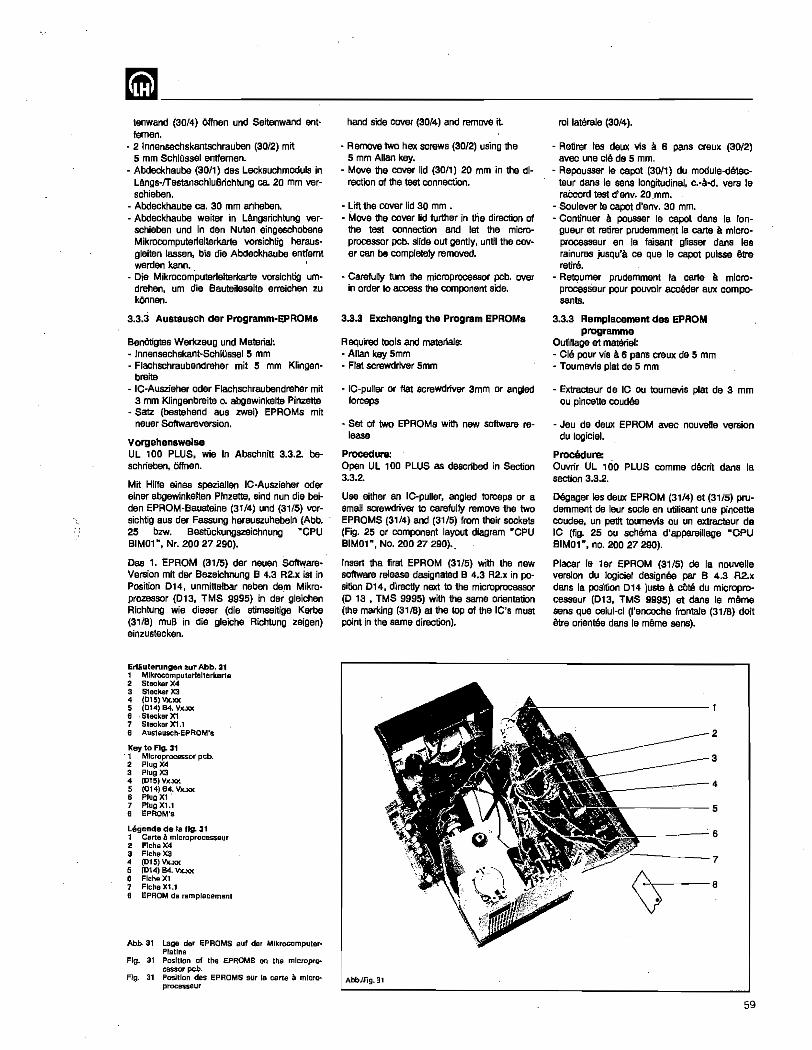
mm ______ ~------------------tenwand (30/4) Offnsn und Seitenwand antfemen.
- 2 Innensechskantschrauben (30/2) mit 5 mm SchlOssel entfemen.
- Abcleckhaube (30/1) des Lecksuchmoduls in Langs-lTestanschluBrichtung ca. 20 mm verschieben.
- Abcieckhaube ca. 30 mm anheben. - Abdeckhaube waiter in Ungsrichtung ver-
5chieben und in den Nuten eingeschobene MikrocomputerJeiterkarte vorsichtig herausgleitan lassen. bis die Abdeckhaube entfernt werden kann. '
• Die Mikrocomputerleiterkarte vorsichtig umdrehen, urn die Bauteileseite erreichen zu kOnnen.
3.3.3 Austausch der Programm-EPROMs
BenOtigtes Werkzeug und Material~ - Innensechskant-SchlOsseJ 5 mm • Flachschraubendreher mit 5 mm Klingen
breite - IC-Auszieher oder Flachschraubendreher mit
3 mm Klingenbreite o. abgewinkelte Pinzette - 8atz (bestehend 8US zwei) EPROMs mit
neuer Softwareversion.
Vorgehenswelse UL 100 PLUS. wie in Abschnitt 3.3.2. beschrieben, Offnen.
Mit Hilte eines speziellen IC-Auszieher oder einer abgewinkelten Pinzette, sind nun die beiden EPROM-Bausteine (31/4) und (31/5) vorsichtig aus der- Fassung herauszuhebeln (Abb. 25 bzw. BestOckungszeichnung "CPU SIMO'", Nr. 200 27 290).
Oas 1. EPROM (31/5) der neuen SoftwareVersion mit der Bezeichnung 8 4.3 R2.x ist in Position 014, unmittelbar neben dem Mikroprozessor (013, TMS 9995) in der gleichen Richtung wie dieser (die stimseitige Kerbe (31/8) muB in die gleiche Richtung zeigen) einzustecken.
Erliuterungen zur Abb. 31 1 Mlkrocomputorloltorkarle 2 Slecker X4 3 Stecker X3 4 (015)Vx.xx 5 (014) 84. Vx.)(l( 6 SteckorX1 7 SleckorX1.1 8 Auslausch·EPROM's
Key to FIg. 31 . 1 Microprocessor pcb. 2 Plug X4 3 Plug X3 4 (015) Vx.xx 5 (OI4) 84. Vx.xx: 6 Plug XI 7 Plug XU a EPROM's
Legende de la 1Ig. 31 I Cllrte iI mlcroprocesseur 2 Flcha X4 3 Fiche X3 4 (015) Vx.xx 5 (014) B4. Vx.xx: 6 Fiche Xl 7 FlcheXl.1 B EPROM de rem placement
Abb. 3t Lage der EPRQMS auf der MikrocompulerPlallne
Fig. 3t Position of the EPROMS on the microprocessor pcb.
Ag. 31 Posltion des EPROMS sur la carte a microprocesseur
hand side cover (30/4) and remove it
- Remove two hex screws (30/2) using the 5 mm Allan key.
- Move the cover lid (30/1) 20 mm in the direction of the test connection.
- Lift the cover lid 30 mm • - Move the cover lid further in the direction of
the test connection and let the microprocessor pcb. slide out gently. until the cover can be completely removed.
- Carefully tum the microprocessor pcb. over in order to access the component side.
3.3.3 Exchanging the Program EPROMs
Required tools and material$. - Allan key 5mm - Flat screwdriver 5mm
- IC-puller or flat screwdriver 3mm or angled forceps
- Set of two EPROMs with new software re· lease
Procedure: Open UL 100 PLUS as described in Section 3.3.2.
Use either an IC-puller. angled forceps or a small screwdriver to carefully remove the two EPROMS (31/4) and (31/5) from their sockets (Fig. 25 or component layout diagram "CPU SIMO'", No. 200 27 290) •.
Insert the first EPROM (31/5) with the new software release designated 8 4.3 R2.x in position 014, directly next to the microprocessor (0 13 ,TMS 9995) with the same orientation (the marking (311S) at the top of the IC's must point in the same direction).
AbbJFig.31
roi laterale (3014).
- Retirer les deux vis a. 6 pans creux (30/2) avec une cle de 5 mm.
• Repousser Ie capot (30/1) du module·detecteur dans Ie sans longitudinal. C.-8-d. vers Ie rat:cord test d'env. 20.mm.
- Soulever Ie capot d'env. 30 mm. - Continuer a pousser Ie capot dans la lon-
gueur et retirer prudemmer:rt la carte a microprocesseur en la faisant gUsser dans les rainures jusqu's ce que fe capot puisse etre retire.
- Retoumer prudemment la carte a mlcroprocesseur pour pouvoir acceder aux composants.
3.3.3 Remplacement dea EPROM programme
Outillage at materiel: - Cia pour vis a 6 pan's creux de 5 mm - Toumevis plat de 5 mm
- Extracteur de IC aU tournevis plat de 3 mm au pincette coudae
- Jeu de deux EPROM avec nouvelle version du logiciel.
ProciJdure: Ouvrir UL 100 PLUS comme decrit dans la section 3.3.2.
Degager las deux EPROM (31/4) at (31/5) prudemment de leur socle en utilisant une pincette caudae, un petit toumevis ou un extracteur de IC (fig. 25 ou schama d'appareiIJage "CPU SIMO'", no. 200 27 290).
Placer Ie ler EPROM (31/S) de la nouvelle version du logiciel designee par B 4.3 R2.x dans Ie poSition 014 justa a cOte du micropro· cesseur (013, TMS 9995) at dans Ie meme sans qua celui-ci (I'encoche frontale (31/8) doit etra orientes dans Ie mArne sens).
2
3
____ -4
-----5
>-____ 6
----7
59

--------------------------~ Das 2. EPROM (31/4) der neuen SoftwareVersion mit der Bezeichnung R2.x ist in Position 015 in der gleichen Richtung wie 014 einzustecken.
3.3.4 Elnbau der Mlkrocomputerlelter~ karte
Die Mikrocorriputerleiterkarte ist in die Ausgangsla'ge (Bauteile nach unten) zu drehen.
Die Mikrocomputer[eiterkarte ist wieder in die Fuhrungsnuten der Abcleckhaube (3011) einzuschieben. MOglicherwaise 1st der PerlinaxAbstandsstreifen herausgefaJlen und muB in diesem Fall zuersl, var der Mikrocomputerleiterkarte in die gleichen FOhrungsschlitze eingeschoben werden.
Bavor die Abcleckhauba wieder vollstandig auf die geschlitzten FOhrungsbolzen aufgesetzt wird, noah alnma! aile Steckvorrichtungen auf korrekten Sitz prOfsn.
Die Abdeckhaube ist mit Btwas Kraft in Richtung rachter Seitenwand in die Ursprungslage zurQckzuschieben.
Die zwei Innensechskantschrauben (30/2) sind wieder einzuschrauben und mit dam 5 mm Schlussel fest anzudrehen.
Rachte Seitenwand wieder anbringen.
Zurn Test der erfolgreichen Installation der neuen Software-VerSion ist der Ul100 wie gewohnt in Betrieb zu nehmen. Es sollte zunachst festgestelft werden, ob in der Statusanzeige die richtige Software-Version angezeigt wird. Nach Erreichen des "STBY"·Zustands mOssen die Funktionen entsprachend Abschnitt 2 ausfOhrbar saln.
Die altan Programm-EPROMs bitta an LEYBOLD AG in 5000 KOln- 51, Postfach 510 760, Abt APE 22 zurQcksenden.
3.4 Service Oer Statusreport gibt im Servicefall wichtige Informationsn Ober den internen Zustand des Ul10a PLUS. Oer Statusreport ist jedach nur tiber die RS 232-C-Schnittstelle auslasbar. Siehe hierzu die Schnittstellenbeschreibung 5810.207.
Allgemeine Hlnwelse Eine Anderung der Konstruktion und der angegebenen Daten behaJten wir uns vcr. Die Abbildungen sind unverbindlich.
Insert the second EPROM (31/4) with the new software release designated R2.x in poSition 0 15 with the same orientation as 014. Inspect both sides of both chips ta ensure that every pin is properly insarted in the socket
3.3.4 Reassembly of the Microprocessor PCB
Bring the microprocessor pcb. back to the initial position with the components facing downwards.
Insert the microprocessor pcb. into the guide grooves of the cover lid (30/1). Possibly the Pertinax spacer has fallen out, and if so, it must be inserted into the same guide grooves before inserting the microprocessor pcb.
Before placing the cover lid on the slotted guides it is advisable to check the seating of all the connector~.
Push the cover lid in the direction of the side cover using a little pressure so that the cover is pushed back into the initial position.
Screw in two hex screws (30/2) and tighten them with the 5 mm Allan key.
Again attach the side cover.
For testing of the new software release sWitch on the UL 100 PLUS as usual. First look at the status display to see if the right software release is indicated. Then after reaching the "STBY" status the new functions as described in Section 2 must be executable.
Please return the old EPROMs to your local lEYBOLD sales or service office.
. 3.4 Service The status report provides important information on the internal status of the UL 100 PLUS in the case of servicing. However, the status report can only be output via the RS 232 C interface. For this refer to the interface description given in the Service Manual 5810.207.
General Remartc8 We reserve the right to alter the design or any data given in these Operating Instructions. The illustrations are not bindinl;l.
Placer Ie 28me EPROM (31/4) de la nouvelle version du logiciel, designee par R2.x. dans-Ia position 015 at dans Ie merne sans que 014.
3.3.4 Montage de la carte a mlcroprocesseur
Retourner la carte A microprocesseur pour que Ie composant soit orienta vers Ie bas.
La glisser de nouveau dans les rainures du capo! (3011). 51 la band. d'Ocartoment en Pertinax est tombee iI faut la remetb'e dans las rainures avant de glisser la carte.
Verifier la bonne flXBtion de taus las connecteurs avant de replacer Ie capot sur les guides fendus.
Repousser Ie capot un peu fortement en direction de Ia paroi laterals droite jusqu'a ce qu'j[ revienne en position d'origine.
Revisser las deux vis a 6 pans creux (30/2) at las bloquer avec la cle de 5 mm.
Remonter la paroi laterals.
Meltre UL 100 PLUS en service comme d'ha· bitude pour verifier 51 I'installation de Ie. version du logiciel donne satisfaction. La nouvelle version do logiciel doit apparaitre dans j'affichage. Lorsque I'apparej[ attaint Ie mode !'STBY", les fonctions decrites dans 2 doivent 01r0 executahlos.
Renvoyer s.v.p., las anciens EPROM a LEY· BOLD AG, Service APE 22, botte postale 510 760,5000 Cologne 51, RFA.
3.4 Service Le rapport d'etat donne des informations, importantes pour les reparations, concernant I'etat interne de UL 100 PLUS. Toutefois Ie rapport d'etat n'est lisible que par l'interface:RS 232 C. Voir pour eela la description de I'interface 5910.207.
Remarques g6nerales Nous nous reservons Ie droft de modifier la construction at les indications donnees. Les figures sont sans engagement
LEYBOLO AG '. Bonner StraBe 498 . Postfach 51 0760 . 0-5000 Katn 51 . Telefon (0221) 347-0 . Telefax (0221) 347-12 50 • Telex 888481-20 Ih d OFS 2,0-3-93 Printed in Germany
60