
Layout process of a gear set Step by Step - KISSsoft · Layout process of a gear set – Step by...
29
Slide 1 05.09.2016 KISSsoft AG www.KISSsoft.AG SHARING KNOWLEDGE Layout process of a gear set – Step by Step
Transcript of Layout process of a gear set Step by Step - KISSsoft · Layout process of a gear set – Step by...

Slide 1
05.09.2016
KISSsoft AG
www.KISSsoft.AG
SHARING KNOWLEDGE
Layout process of a gear set –
Step by Step

Slide 2
05.09.2016 www.KISSsoft.AG
Layout process of a gear set

Slide 3
05.09.2016 www.KISSsoft.AG
Stage I

Slide 4
05.09.2016 www.KISSsoft.AG
Lay out of: Raw dimensions
Performances achieved by a raw sizing function
In a typical example here
Weight 19.5 .. 57.7 kg
(a: 220..355 mm; b: 35..135 mm)
Cost variation in the range of: 34-100 %
(with the same torque capacity)

Slide 5
05.09.2016 www.KISSsoft.AG
Stage II

Slide 6
05.09.2016 www.KISSsoft.AG
Lay out of: Macro Geometry
Performances achieved by a Macro Geometry sizing function
In a typical example here
Torque capacity: 1020-1740 Nm 58-100%;
Losses: 0.12 - 0.50% 42-100%
Micropitting Slam: 0.7-2.7 26-100% etc.
(with the same centre distance a and face width b)

Slide 7
05.09.2016 www.KISSsoft.AG
Stage III: Layout of the Micro Geometry
The last phase in sizing a gear pair is to specify the flank line and profile
modifications (also known as the "micro geometry").
To do so, the primary objective for which optimization has to be achieved:
noise, service life, scuffing, micropitting or efficiency must be selected.
The calculation method for proving the effects achieved by micro geometry,
the contact analysis under load ("Loaded Tooth Contact Analysis", or LTCA),
is complex and time-consuming.
Unfortunately, the interpretation of LTCA results is not easy. All modifications applied on mating gears are interacting, so the decision of which modification to add or to change is difficult.

Slide 8
05.09.2016 www.KISSsoft.AG
Stage III

Slide 9
05.09.2016 www.KISSsoft.AG
Stage III: Layout of the Micro Geometry
For a targeted sizing of the micro geometry, a step-by-step approach should
be used, first specifying the flank line modification and then the profile
modification.
A three-step process is proposed to perform a targeted sizing:
Step III/1: Layout of the theoretical flank line modifications
Step III/2: Including flank line manufacturing tolerances
Step III/3: Layout profile modifications

Slide 10
05.09.2016 www.KISSsoft.AG
Step III/1: Layout of the theoretical flank
line modifications
Proposition for an optimal flank line
modification to get uniform load
distribution for a single stage load
(Input gear stage of the two-stage-
industrial gearbox)
Load distribution before sizing Load distribution after sizing

Slide 11
05.09.2016 www.KISSsoft.AG
Step III/2: Including flank line
manufacturing tolerances
Main manufacturing tolerances having impact on the load distribution
(according ISO6336) are:
- fHb for the lead variation of the gears (fHbT1+fHbT2)
- fma for the axis misalignment in the contact plane)
According ISO6336-1, Annex E, KHb has to be calculated five times: Without
tolerance, than with +fHb & +fma, +fHb & -fma, -fHb & +fma, -fHb & -fma. The
highest KHb–value found will be used in the load capacity calculations.

Slide 12
05.09.2016 www.KISSsoft.AG
Step III/2: Including flank line
manufacturing tolerances
When no expertise is available, the following procedure can be applied.
In ISO 6336-1, Annex B, for gears having a flank line modification to
compensate for deformation, the crowning amount
Cb = fHβT (1)
is proposed.
When such an additional modification is applied, clearly the load distribution
over the face width as obtained in step 1 is not anymore uniform distributed.
Therefore the face load factor KHb will increase. The goal is to avoid edge
contact in all possible combination of deviations.

Slide 13
05.09.2016 www.KISSsoft.AG
Step III/2: Including flank line
manufacturing tolerances For all five combinations (0, +fHb & +fma, +fHb & -fma, -fHb & +fma, -fHb & -fma),
the line load distribution in the operating pitch diameter has to be calculated
and checked for edge contact).
Load distribution with different manufacturing deviation values.

Slide 14
05.09.2016 www.KISSsoft.AG
Step III/3: Profile modifications
When the flank line modification is defined, the third step is to specify the
profile modifications. Important features such as noise, losses, micropitting,
scoring and wear can be improved by profile modifications. Therefore the
layout criteria must be defined. Then the corresponding strategy is used.
Layout for low-noise:
Contact shock: Gear pair meshing and path of contact calculated with LTCA, showing the prolonged contactat start and end of the mesh.
PPTE: Peak-to-Peak Transmission error

Slide 15
05.09.2016 www.KISSsoft.AG
Step 3: Use of a ‘modification sizing’ tool
to find optimum design
Tab. I: Contains all modifications which will not be changed
Tab. II: Definition of modifications which will be varied (here: Profile crowning)
Optimization of profile modifications in a case-by-case manneris extremely time-consuming and demanding.
“Analysis of modification variants” tool: Profile crowning variants

Slide 16
05.09.2016 www.KISSsoft.AG
Step III/3: Use of a ‘modification sizing’
tool to find optimum design
Table with
numbered
variants and
selected main
results

Slide 17
05.09.2016 www.KISSsoft.AG
Step III/3: Use of a ‘modification sizing’
tool to find optimum design
Two charts with results (PPTE and efficiency) of 25 modification variants
Red: At 100 precent load; Blue: At 75 precent load

Slide 18
05.09.2016 www.KISSsoft.AG
Step III/3: Use of a ‘modification sizing’
tool to find optimum design
Tab. I: Contains all modifications which will not be changed
Tab. II: Definition of modifications which will be varied (here arc-like tip relief)
“Analysis of modification variants” tool: Tip relief variants
Slide 19
05.09.2016 www.KISSsoft.AG
Step III/3: Use of a ‘modification sizing’
tool to find optimum design
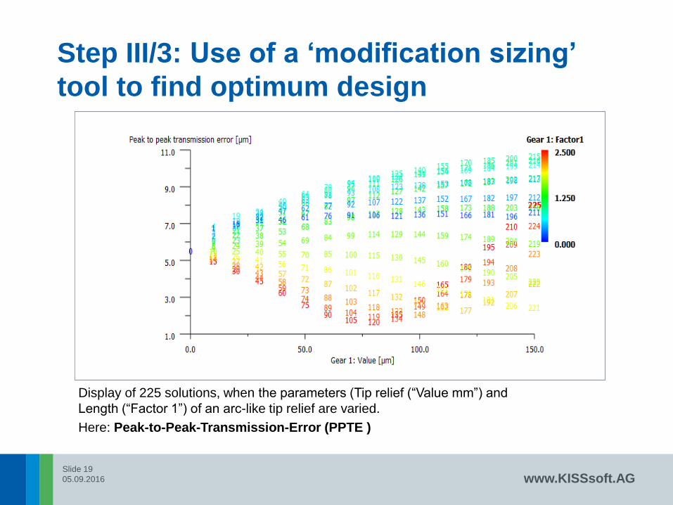
Display of 225 solutions, when the parameters (Tip relief (“Value mm”) and
Length (“Factor 1”) of an arc-like tip relief are varied.
Here: Peak-to-Peak-Transmission-Error (PPTE )

Slide 20
05.09.2016 www.KISSsoft.AG
Step III/3: Use of a ‘modification sizing’
tool to find optimum design
Display of 225 solutions, when the parameters (Tip relief (“Value mm”) and
Length (“Factor 1”) of an arc-like tip relief are varied.
Here: Maximum Hertzian Pressure

Slide 21
05.09.2016 www.KISSsoft.AG
Step III/3: Use of a ‘modification sizing’
tool to find optimum design
Display of 225 solutions, when the parameters (Tip relief (“Value mm”) and
Length (“Factor 1”) of an arc-like tip relief are varied.
Here: Efficiency

Slide 22
05.09.2016 www.KISSsoft.AG
Step III/3: Use of a ‘modification sizing’
tool to find optimum design
Display of 225 solutions, when the parameters (Tip relief (“Value mm”) and
Length (“Factor 1”) of an arc-like tip relief are varied.
Here: Safety factor against Micropitting

Slide 23
05.09.2016 www.KISSsoft.AG
Step III/3: Use of a ‘modification sizing’
tool to find optimum design
Display of 225 solutions, when the parameters (Tip relief (“Value mm”) and
Length (“Factor 1”) of an arc-like tip relief are varied.
Here: Safety factor against Tooth Flank Fracture (TFF)

Slide 24
05.09.2016 www.KISSsoft.AG
Step III/3: Finish
End of Step III/3:
- Make a first selection of best variants (profile modifications)
- Check the LTCA results of these variants
- Choose the best over all variant
- Recheck load distribution *)
Method is successfully tested:
The time used by the design engineer to find optimum
modifications for both stages of a gearbox was 15 minutes.
*) Normally the load distibution as defined in Step III/2 is
tipically not much changed by the added profile modifications.

Slide 25
05.09.2016 www.KISSsoft.AG
Considering housing and/or planet carrier
stiffness
In any KISSsys model the housing stiffness can be considered using a
stiffness matrix imported from a FEM software. The resulting housing
deformation at the bearing positions are shown in a results table. The
deformations are assigned to the bearings (typically outer ring) in the shaft
calculation and considered in the gear contact analysis.
A stiffness matrix, created by FEM, is included in a KISSsys model. Thus, the
housing stiffness is considered in the load distribution analysis.Bearing outer ring
displacements in mm
(x, y: horizontal;
z: vertical)

Slide 26
05.09.2016 www.KISSsoft.AG
Example: Use of the 3-step-modification sizing
procedure with a industrial 2-stage gearbox
First the load distributions of the two gear pairs without modifications are
calculated. The face load factors are calculated according to Annex E in
ISO6336-1, using the axis deformations from the shaft calculation.
Gear PairKHβ
Without housing deformation
KHβ
With housing deformation
HSS (High speed stage) 1.17 1.16
HSS (Low speed stage) 1.30 1.32
Face load factors without flank line modifications
For a typical industrial two-stage parallel shaft reducer the modifications are optimized using the 3-step method. The process is repeated twice, with and without considering housing stiffness, to get an indication on the influence of the housing.

Slide 27
05.09.2016 www.KISSsoft.AG
Proposed layout procedure Step III/1 to III/3
- The time used by the design engineer to find optimum
modifications for both stages was 15 minutes.
- The optimum flank line modifications as defined in Step 1
are only slightly different when housing stiffness is
considered (only 10% change in the helix angle modification
value).
-The additional modifications in Step 2 and the profile
modifications in Step 3 are identical with and without
consideration of housing stiffness.
-The additional crowning added in Step 2 to compensate for
manufacturing tolerances is much bigger (5 times) than the
difference between modifications in Step 1 used to
compensate shaft deflection with and without considering
housing stiffness. Therefore, for practice-oriented solutions
the influence of the housing stiffness is so small that it is
negligible.

Slide 28
05.09.2016 www.KISSsoft.AG
Conclusion
Raw sizing of major dimensions (Stage I), then fins sizing of macro
geometry parameters (Stage II) and finally optimization of flank line and
profile modifications (Stage III) is a very successful procedure to find the
best gear pair for a specific application .
The last stage, optimization of micro modifications is a difficulty and time
consuming task. The three-step methodology has proven highly successful
since it was introduced two years ago. The layout of the modifications for
an industrial gearbox shows that for a gearbox with parallel shafts including
external forces acting on it, the housing deformations have an insignificant
influence on the resulting gap in the meshing of the gears.
This method can also be used in applications such as wind power, ship
transmission systems, or helicopters in which it is demanding to define the
modifications due to the extreme load spectrum or high housing deflections.

Slide 29
05.09.2016
SHARING KNOWLEDGE
THANK YOU
for your attention!


