Intuvo 9000 GC, GC/MS, and ALS Site Preparation Guide · Agilent Technologies Agilent Intuvo 9000...
58
Agilent Technologies Agilent Intuvo 9000 GC, GC/MS, and ALS Site Preparation Guide
Transcript of Intuvo 9000 GC, GC/MS, and ALS Site Preparation Guide · Agilent Technologies Agilent Intuvo 9000...
Agilent Intuvo 9000 GC, GC/MS, and ALS
Site Preparation Guide
Agilent Technologies
2 9000 GC, GC/MS, and ALS Site Preparation Guide
Notices© Agilent Technologies, Inc. 2017
No part of this manual may be reproduced in any form or by any means (including elec-tronic storage and retrieval or translation into a foreign language) without prior agree-ment and written consent from Agilent Technologies, Inc. as governed by United States and international copyright laws.
Manual Part NumberG4580-90006
EditionThird edition, June 2017 Second edition, February 2017 First edition, September 2016
Printed in USA or China
Agilent Technologies, Inc. 2850 Centerville Road Wilmington, DE 19808 USA
安捷伦科技 (上海)有限公司
上海市浦东新区外高桥保税区
英伦路 412 号
联系电话:(800)820 3278
WarrantyThe material contained in this document is provided “as is,” and is subject to being changed, without notice, in future editions. Further, to the maximum extent permitted by applicable law, Agilent disclaims all warranties, either express or implied, with regard to this manual and any information contained herein, including but not limited to the implied warranties of merchantability and fitness for a particular purpose. Agilent shall not be liable for errors or for incidental or consequential damages in connection with the furnishing, use, or performance of this document or of any information contained herein. Should Agilent and the user have a separate written agreement with warranty terms covering the material in this document that conflict with these terms, the warranty terms in the separate agreement shall control.
Safety Notices
CAUTION
A CAUTION notice denotes a hazard. It calls attention to an operating procedure, practice, or the like that, if not correctly performed or adhered to, could result in damage to the product or loss of important data. Do not proceed beyond a CAUTION notice until the indicated conditions are fully understood and met.
WARNING
A WARNING notice denotes a hazard. It calls attention to an operating procedure, practice, or the like that, if not correctly performed or adhered to, could result in personal injury or death. Do not proceed beyond a WARNING notice until the indicated conditions are fully understood and met.
Contents
1 Intuvo 9000 GC Site Preparation
9000 GC, GC/MS, an
Customer Responsibilities 6
Installation Kit 7
Hydrogen Carrier Gas 9
Dimensions and Weight 10
Power Consumption 14
Common instrument power cord plugs 16
Heat Dissipation 19
Exhaust Venting 20
Hot air 20Other gases 21Exhaust vent fittings 22
Environmental Conditions 23
Gas Selection 25
Gas Purity 27
Gas Supplies 28
General requirements 28Requirements for hydrogen as a carrier gas 30
GC/MS Gas Requirements 31
Gas Plumbing 34
Supply tubing for most carrier and detector gases 36Supply tubing for hydrogen gas 37Two-stage pressure regulators 38Pressure regulator-gas supply tubing connections 38Filters and traps 39
Filter types 39
Cryogenic Cooling Requirements 44
Using carbon dioxide 44Using liquid nitrogen 46
d ALS Site Preparation Guide 3
4
Using compressed air 47
Maximum Length of Cables and Hoses 48
Site LAN Network 49
PC Requirements 51
2 7693A and 7650 Automatic Liquid Sampler Site Preparation
Customer Responsibilities 54
Basic Tools and Consumable Supplies 55
Dimensions and Weight 56
Power Consumption 57
Environmental Conditions 57
Chiller Supplies 58
9000 GC, GC/MS, and ALS Site Preparation Guide
Intuvo 9000 GC, GC/MS, and ALSSite Preparation Guide
1Intuvo 9000 GC Site PreparationCustomer Responsibilities 6
Installation Kit 7
Hydrogen Carrier Gas 9
Dimensions and Weight 10
Power Consumption 14
Heat Dissipation 19
Exhaust Venting 20
Environmental Conditions 23
Gas Selection 25
Gas Purity 27
Gas Supplies 28
GC/MS Gas Requirements 31
Gas Plumbing 34
Cryogenic Cooling Requirements 44
Maximum Length of Cables and Hoses 48
Site LAN Network 49
PC Requirements 51
This section outlines the space and resource requirements for GC, GC/MS, and automatic liquid sampler (ALS) installation. For a successful and timely installation of the instrument, the site must meet these requirements before beginning installation. Necessary supplies (gases, tubing, operating supplies, consumables, and other usage-dependent items such as columns, vials, syringes, and solvents) must also be available. Note that performance verification requires the use of helium carrier gas. For MS systems using chemical ionization, methane reagent gas is also required for performance verification. Refer to the Agilent Web site at www.agilent.com for the most up-to-date listing of GC, GC/MS, and ALS supplies and consumables.
For 7697A Headspace Sampler site prep specifications, refer to the 7697A Site Prep Guide.
5Agilent Technologies
Intuvo 9000 GC Site Preparation
Customer Responsibilities
6
The specifications in this manual outline the necessary space, electrical outlets, gases, tubing, operating supplies, consumables, and other usage-dependent items such as columns, vials, syringes, and solvents required for the successful installation of instruments and systems.
If Agilent is delivering installation and familiarization services, users of the instrument should be present throughout these services; otherwise, they will miss important operational, maintenance, and safety information.
If Agilent is delivering installation and familiarization services, delays due to inadequate site preparation could cause loss of instrument use during the warranty period. In extreme cases, Agilent Technologies may ask to be reimbursed for the additional time required to complete the installation. Agilent Technologies provides service during the warranty period and under maintenance agreements only if the specified site requirements are met.
9000 GC, GC/MS, and ALS Site Preparation Guide
Intuvo 9000 GC Site Preparation
Installation Kit
9000 GC, GC/MS, an
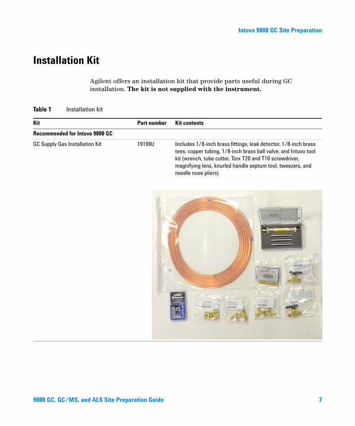
Agilent offers an installation kit that provide parts useful during GC installation. The kit is not supplied with the instrument.
Table 1 Installation kit
Kit Part number Kit contents
Recommended for Intuvo 9000 GC
GC Supply Gas Installation Kit 19199U Includes 1/8-inch brass fittings, leak detector, 1/8-inch brass tees, copper tubing, 1/8-inch brass ball valve, and Intuvo tool kit (wrench, tube cutter, Torx T20 and T10 screwdriver, magnifying lens, knurled handle septum tool, tweezers, and needle nose pliers)
d ALS Site Preparation Guide 7
Intuvo 9000 GC Site Preparation
8
You must also provide the fittings and reducers required to convert the cylinder regulator fitting (for example, 1/4-inch male NPT) to the 1/8-inch female Swagelok fitting needed to connect to the instrument. These fittings are not included with the GC. These fittings are not included with the installation kits.
9000 GC, GC/MS, and ALS Site Preparation Guide
Intuvo 9000 GC Site Preparation
Hydrogen Carrier Gas
9000 GC, GC/MS, an
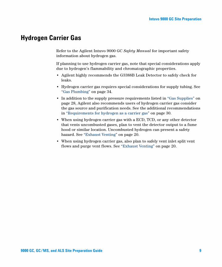
Refer to the Agilent Intuvo 9000 GC Safety Manual for important safety information about hydrogen gas.
If planning to use hydrogen carrier gas, note that special considerations apply due to hydrogen’s flammability and chromatographic properties.
• Agilent highly recommends the G3388B Leak Detector to safely check for leaks.
• Hydrogen carrier gas requires special considerations for supply tubing. See “Gas Plumbing” on page 34.
• In addition to the supply pressure requirements listed in “Gas Supplies” on page 28, Agilent also recommends users of hydrogen carrier gas consider the gas source and purification needs. See the additional recommendations in “Requirements for hydrogen as a carrier gas” on page 30.
• When using hydrogen carrier gas with a ECD, TCD, or any other detector that vents uncombusted gases, plan to vent the detector output to a fume hood or similar location. Uncombusted hydrogen can present a safety hazard. See “Exhaust Venting” on page 20.
• When using hydrogen carrier gas, also plan to safely vent inlet split vent flows and purge vent flows. See “Exhaust Venting” on page 20.
d ALS Site Preparation Guide 9
Intuvo 9000 GC Site Preparation
Dimensions and Weight
10
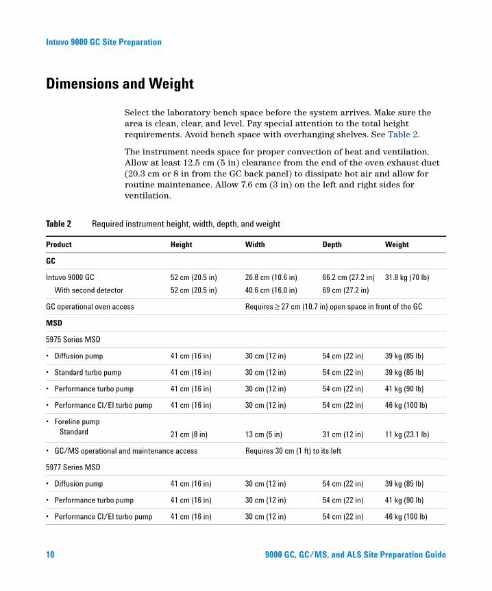
Select the laboratory bench space before the system arrives. Make sure the area is clean, clear, and level. Pay special attention to the total height requirements. Avoid bench space with overhanging shelves. See Table 2.
The instrument needs space for proper convection of heat and ventilation. Allow at least 12.5 cm (5 in) clearance from the end of the oven exhaust duct (20.3 cm or 8 in from the GC back panel) to dissipate hot air and allow for routine maintenance. Allow 7.6 cm (3 in) on the left and right sides for ventilation.
Table 2 Required instrument height, width, depth, and weight
Product Height Width Depth Weight
GC
Intuvo 9000 GC
With second detector
52 cm (20.5 in)
52 cm (20.5 in)
26.8 cm (10.6 in)
40.6 cm (16.0 in)
66.2 cm (27.2 in)
69 cm (27.2 in)
31.8 kg (70 lb)
GC operational oven access Requires ≥ 27 cm (10.7 in) open space in front of the GC
MSD
5975 Series MSD
• Diffusion pump 41 cm (16 in) 30 cm (12 in) 54 cm (22 in) 39 kg (85 lb)
• Standard turbo pump 41 cm (16 in) 30 cm (12 in) 54 cm (22 in) 39 kg (85 lb)
• Performance turbo pump 41 cm (16 in) 30 cm (12 in) 54 cm (22 in) 41 kg (90 lb)
• Performance CI/EI turbo pump 41 cm (16 in) 30 cm (12 in) 54 cm (22 in) 46 kg (100 lb)
• Foreline pumpStandard 21 cm (8 in) 13 cm (5 in) 31 cm (12 in) 11 kg (23.1 lb)
• GC/MS operational and maintenance access Requires 30 cm (1 ft) to its left
5977 Series MSD
• Diffusion pump 41 cm (16 in) 30 cm (12 in) 54 cm (22 in) 39 kg (85 lb)
• Performance turbo pump 41 cm (16 in) 30 cm (12 in) 54 cm (22 in) 41 kg (90 lb)
• Performance CI/EI turbo pump 41 cm (16 in) 30 cm (12 in) 54 cm (22 in) 46 kg (100 lb)
9000 GC, GC/MS, and ALS Site Preparation Guide

Intuvo 9000 GC Site Preparation
• Foreline pumpStandard
Oil-free (MVP-070)
Oil-free (IDP3)
21 cm (8 in)
19 cm (7.5 in)
18 cm (7 in)
13 cm (5 in)
32 cm (13 in)
35 cm (14 in)
31 cm (12 in)
28 cm (11 in)
14 cm (6 in)
11 kg (23.1 lb)
16 kg (35.2 lb)
10 kg (21 lb)
• GC/MS operational and maintenance access Requires 30 cm (1 ft) to its left
MS
7010 and 7000 Triple Quad MS
• EI Mainframe 47 cm (18.5 in) 35 cm (14 in) 86 cm (34 in) 59 kg (130 lb)
• EI/CI Mainframe 47 cm (18.5 in) 35 cm (14 in) 86 cm (34 in) 63.5 kg (140 lb)
• Foreline pump 28 cm (11 in) 18 cm (7 in) 35 cm (14 in) 21.5 kg (47.3 lb)
• GC/MS operational and maintenance access Requires 30 cm (1 ft) to its left
ALS
• GC with 7693A ALS injector Requires 50 cm (19.5 in) above the GC 3.9 kg (8,6 lb) each
• GC with 7693A ALS tray Requires 43 cm (16.8 in) left of the GC Requires 4.2 cm (1.7 inch) in front of GC
6.8 kg (15 lb) each
• GC with 7650A ALS injector Requires 50 cm (19.5 in) above the GC 4.4 kg (9.8 lb) each
Table 2 Required instrument height, width, depth, and weight (continued)
Product Height Width Depth Weight
9000 GC, GC/MS, an
A system that includes an Intuvo 9000 GC, a 5977, 5975, 7010 or 7000 MS, an ALS, and a computer would require about 168 cm (5.5 ft) of bench space (see Figure 1). A 7890 Series system with a GC, Ion Trap MS, ALS, and computer would require about 206 cm (6.7 ft) of bench space (or 148 cm [4.8 ft] excluding the area under the tray.) See Figure 3. Allowing for operational access and a printer, a total of 260 cm (8.5 ft) of bench space should be available for a quadrupole GC/MS system and 298 cm (9.7 ft) should be available for an Ion Trap GC/MS system. Some repairs to the GC/MS or to the GC will also require access to the back of the instrument(s).
d ALS Site Preparation Guide 11
Intuvo 9000 GC Site Preparation
12
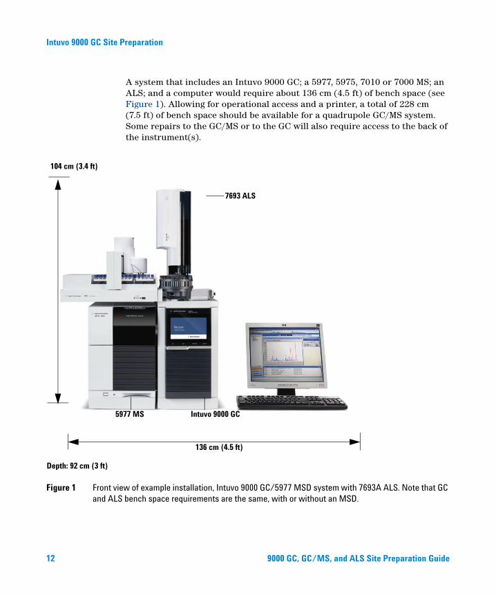
A system that includes an Intuvo 9000 GC; a 5977, 5975, 7010 or 7000 MS; an ALS; and a computer would require about 136 cm (4.5 ft) of bench space (see Figure 1). Allowing for operational access and a printer, a total of 228 cm (7.5 ft) of bench space should be available for a quadrupole GC/MS system. Some repairs to the GC/MS or to the GC will also require access to the back of the instrument(s).
Figure 1 Front view of example installation, Intuvo 9000 GC/5977 MSD system with 7693A ALS. Note that GC and ALS bench space requirements are the same, with or without an MSD.
104 cm (3.4 ft)
Depth: 92 cm (3 ft)
136 cm (4.5 ft)
5977 MS Intuvo 9000 GC
7693 ALS
9000 GC, GC/MS, and ALS Site Preparation Guide
Intuvo 9000 GC Site Preparation
9000 GC, GC/MS, an
Note that the length of the quadrupole vacuum hose is 130 cm (4 ft 3 in) from the high vacuum pump to the foreline pump, and the length of the foreline pump power cord is 2 m (6 ft 6 in).
An Intuvo 9000 GC shipping container for a GC is approximately 76 cm × 86 cm × 10 cm (30 × 34 × 40.5 inches). If you purchased a second detector option, the second detector arrives separately in a shipping container is approximately 76 cm × 87 cm × 11 cm (30 × 34 × 42.5 inches).
d ALS Site Preparation Guide 13
Intuvo 9000 GC Site Preparation
Power Consumption
14
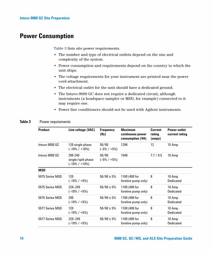
Table 3 lists site power requirements.
• The number and type of electrical outlets depend on the size and complexity of the system.
• Power consumption and requirements depend on the country to which the unit ships.
• The voltage requirements for your instrument are printed near the power cord attachment.
• The electrical outlet for the unit should have a dedicated ground.
• The Intuvo 9000 GC does not require a dedicated circuit, although instruments (a headspace sampler or MSD, for example) connected to it may require one.
• Power line conditioners should not be used with Agilent instruments.
Table 3 Power requirements
Product Line voltage (VAC) Frequency (Hz)
Maximum continuous power consumption (VA)
Current rating (amps)
Power outlet current rating
Intuvo 9000 GC 120 single phase (–10% / +10%)
50/60 (–5% / +5%)
1296 12 15 Amp
Intuvo 9000 GC 200-240 single/split phase (–10% / +10%)
50/60 (–5% / +5%)
1548 7.7 / 6.5 10 Amp
MSD
5975 Series MSD 120 (–10% / +5%)
50/60 ± 5% 1100 (400 for foreline pump only)
8 10 Amp Dedicated
5975 Series MSD 220–240 (–10% / +5%)
50/60 ± 5% 1100 (400 for foreline pump only)
8 10 Amp Dedicated
5975 Series MSD 200 (–10% / +5%)
50/60 ± 5% 1100 (400 for foreline pump only)
8 10 Amp Dedicated
5977 Series MSD 120 (–10% / +5%)
50/60 ± 5% 1100 (400 for foreline pump only)
8 10 Amp Dedicated
5977 Series MSD 220–240 (–10% / +5%)
50/60 ± 5% 1100 (400 for foreline pump only)
8 10 Amp Dedicated
9000 GC, GC/MS, and ALS Site Preparation Guide
Intuvo 9000 GC Site Preparation
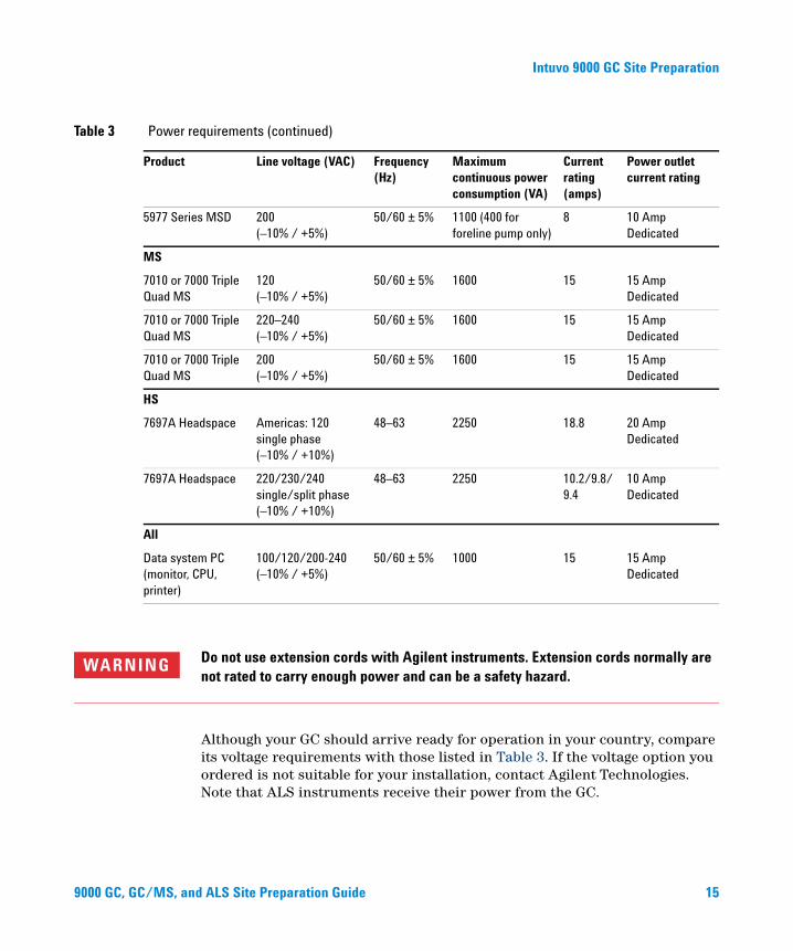
5977 Series MSD 200 (–10% / +5%)
50/60 ± 5% 1100 (400 for foreline pump only)
8 10 Amp Dedicated
MS
7010 or 7000 Triple Quad MS
120 (–10% / +5%)
50/60 ± 5% 1600 15 15 Amp Dedicated
7010 or 7000 Triple Quad MS
220–240 (–10% / +5%)
50/60 ± 5% 1600 15 15 Amp Dedicated
7010 or 7000 Triple Quad MS
200 (–10% / +5%)
50/60 ± 5% 1600 15 15 Amp Dedicated
HS
7697A Headspace Americas: 120 single phase (–10% / +10%)
48–63 2250 18.8 20 Amp Dedicated
7697A Headspace 220/230/240 single/split phase (–10% / +10%)
48–63 2250 10.2/9.8/ 9.4
10 Amp Dedicated
All
Data system PC (monitor, CPU, printer)
100/120/200-240 (–10% / +5%)
50/60 ± 5% 1000 15 15 Amp Dedicated
Table 3 Power requirements (continued)
Product Line voltage (VAC) Frequency (Hz)
Maximum continuous power consumption (VA)
Current rating (amps)
Power outlet current rating
9000 GC, GC/MS, an
WARNING Do not use extension cords with Agilent instruments. Extension cords normally are not rated to carry enough power and can be a safety hazard.
Although your GC should arrive ready for operation in your country, compare its voltage requirements with those listed in Table 3. If the voltage option you ordered is not suitable for your installation, contact Agilent Technologies. Note that ALS instruments receive their power from the GC.
d ALS Site Preparation Guide 15
Intuvo 9000 GC Site Preparation
16
CAUTION A proper earth ground is required for GC operations. Any interruption of the grounding conductor or disconnection of the power cord could cause a shock that could result in personal injury.
To protect users, the metal instrument panels and cabinet are grounded through the three-conductor power line cord in accordance with International Electrotechnical Commission (IEC) requirements.
The three-conductor power line cord, when plugged into a properly grounded receptacle, grounds the instrument and minimizes shock hazard. A properly grounded receptacle is one that is connected to a suitable earth ground. Be sure to verify proper receptacle grounding. The GC requires an isolated ground.
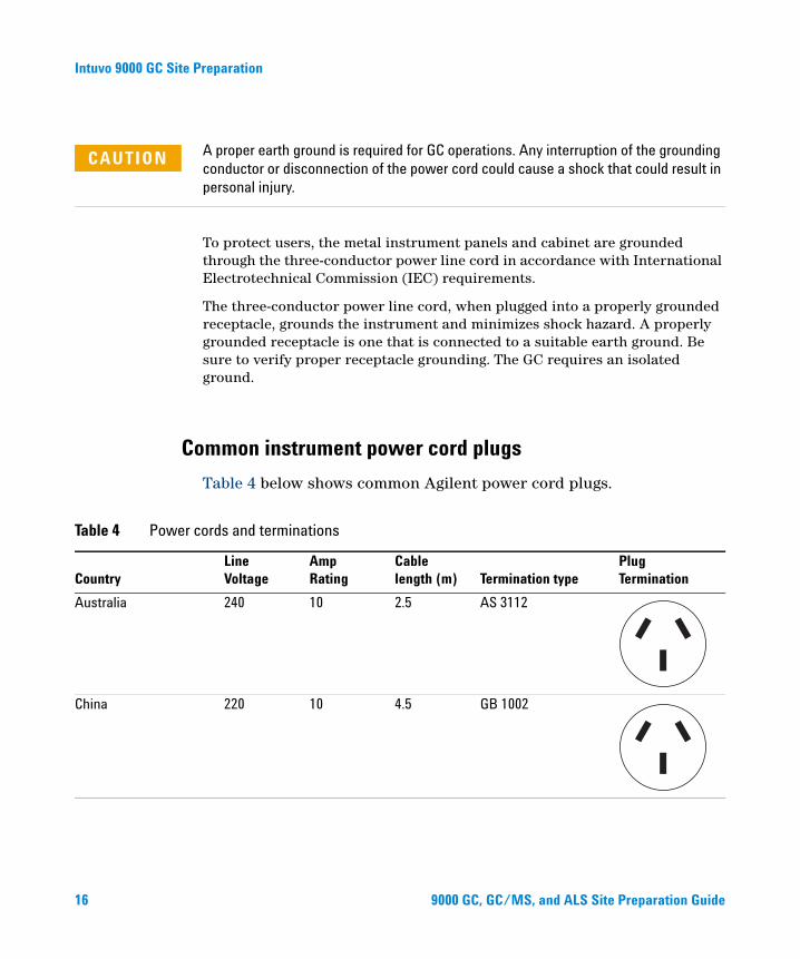
Common instrument power cord plugs
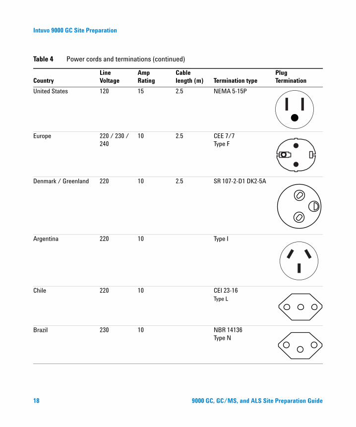
Table 4 below shows common Agilent power cord plugs.
Table 4 Power cords and terminations
Country
Line Voltage
Amp Rating
Cable length (m)
Termination type
Plug Termination
Australia 240 10 2.5 AS 3112
China 220 10 4.5 GB 1002
9000 GC, GC/MS, and ALS Site Preparation Guide
Intuvo 9000 GC Site Preparation
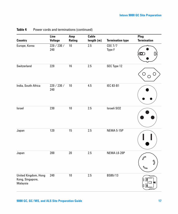
Europe, Korea 220 / 230 / 240
10 2.5 CEE 7/7 Type F
Switzerland 220 16 2.5 SEC Type 12
India, South Africa 220 / 230 / 240
10 4.5 IEC 83-B1
Israel 230 10 2.5 Israeli SI32
Japan 120 15 2.5 NEMA 5-15P
Japan 200 20 2.5 NEMA L6-20P
United Kingdom, Hong Kong, Singapore, Malaysia
240 10 2.5 BS89/13
Table 4 Power cords and terminations (continued)
Country
Line Voltage
Amp Rating
Cable length (m)
Termination type
Plug Termination
9000 GC, GC/MS, and ALS Site Preparation Guide 17
Intuvo 9000 GC Site Preparation
United States 120 15 2.5 NEMA 5-15P
Europe 220 / 230 / 240
10 2.5 CEE 7/7 Type F
Denmark / Greenland 220 10 2.5 SR 107-2-D1 DK2-5A
Argentina 220 10 Type I
Chile 220 10 CEI 23-16Type L
Brazil 230 10 NBR 14136 Type N
Table 4 Power cords and terminations (continued)
Country
Line Voltage
Amp Rating
Cable length (m)
Termination type
Plug Termination
18 9000 GC, GC/MS, and ALS Site Preparation Guide
Intuvo 9000 GC Site Preparation
Heat Dissipation
9000 GC, GC/MS, an
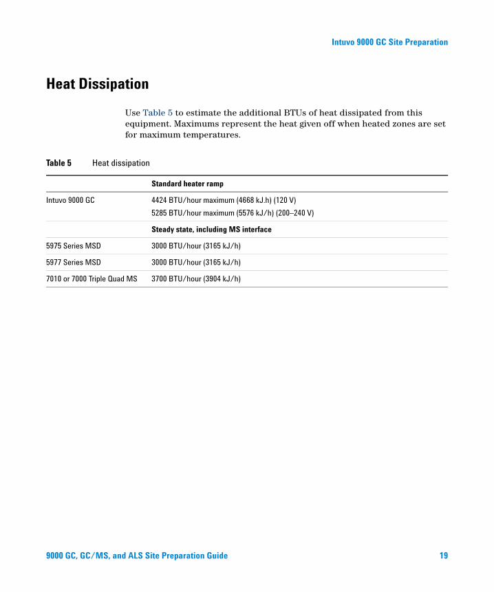
Use Table 5 to estimate the additional BTUs of heat dissipated from this equipment. Maximums represent the heat given off when heated zones are set for maximum temperatures.
Table 5 Heat dissipation
Standard heater ramp
Intuvo 9000 GC 4424 BTU/hour maximum (4668 kJ.h) (120 V)
5285 BTU/hour maximum (5576 kJ/h) (200–240 V)
Steady state, including MS interface
5975 Series MSD 3000 BTU/hour (3165 kJ/h)
5977 Series MSD 3000 BTU/hour (3165 kJ/h)
7010 or 7000 Triple Quad MS 3700 BTU/hour (3904 kJ/h)
d ALS Site Preparation Guide 19
Intuvo 9000 GC Site Preparation
Exhaust Venting
20
During normal operation, the GC exhausts hot air. Depending on the installed inlet and detector types, the GC can also exhaust (or vent) uncombusted carrier gas and sample. Proper venting of these exhausts is required for operation and safety.
Hot air
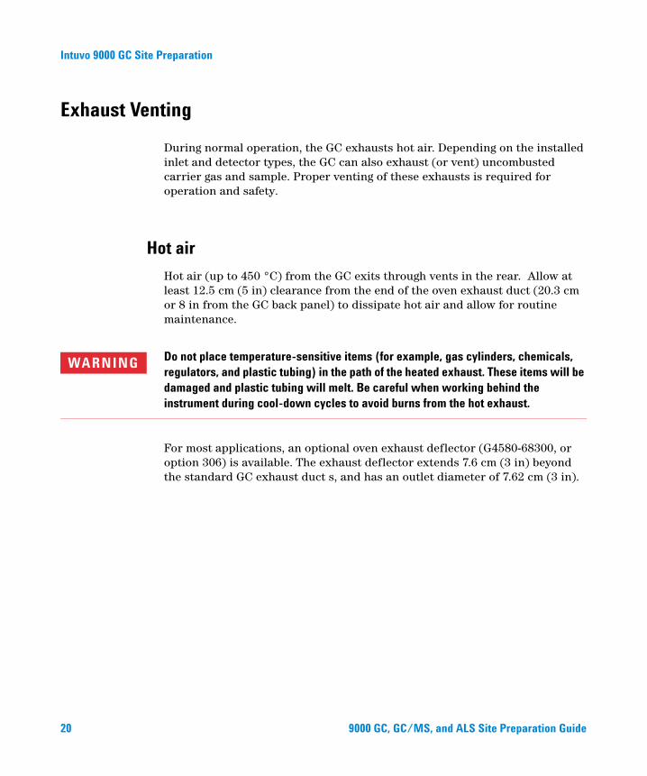
Hot air (up to 450 °C) from the GC exits through vents in the rear. Allow at least 12.5 cm (5 in) clearance from the end of the oven exhaust duct (20.3 cm or 8 in from the GC back panel) to dissipate hot air and allow for routine maintenance.
WARNING Do not place temperature-sensitive items (for example, gas cylinders, chemicals, regulators, and plastic tubing) in the path of the heated exhaust. These items will be damaged and plastic tubing will melt. Be careful when working behind the instrument during cool-down cycles to avoid burns from the hot exhaust.
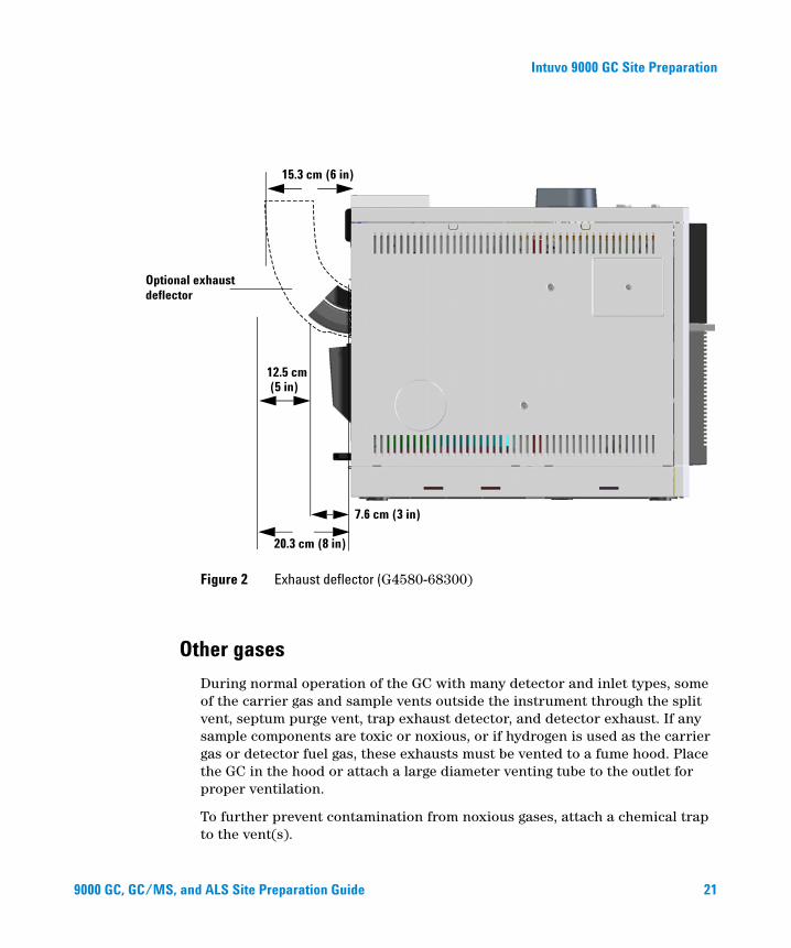
For most applications, an optional oven exhaust deflector (G4580-68300, or option 306) is available. The exhaust deflector extends 7.6 cm (3 in) beyond the standard GC exhaust duct s, and has an outlet diameter of 7.62 cm (3 in).
9000 GC, GC/MS, and ALS Site Preparation Guide
Intuvo 9000 GC Site Preparation
9000 GC, GC/MS, an
Optional exhaust
20.3 cm (8 in)
15.3 cm (6 in)
7.6 cm (3 in)
12.5 cm (5 in)
deflector
Figure 2 Exhaust deflector (G4580-68300)
Other gases
During normal operation of the GC with many detector and inlet types, some of the carrier gas and sample vents outside the instrument through the split vent, septum purge vent, trap exhaust detector, and detector exhaust. If any sample components are toxic or noxious, or if hydrogen is used as the carrier gas or detector fuel gas, these exhausts must be vented to a fume hood. Place the GC in the hood or attach a large diameter venting tube to the outlet for proper ventilation.
To further prevent contamination from noxious gases, attach a chemical trap to the vent(s).
d ALS Site Preparation Guide 21
Intuvo 9000 GC Site Preparation
22
If using a ECD, always plan to connect the ECD exhaust vent to a fume hood or vent it to the outside. See the latest revision of 10 CFR Part 20 (including Appendix B), or the applicable state regulation. For other countries, consult with the appropriate agency for equivalent requirements. Agilent recommends a vent line internal diameter of 6 mm (1/4-inch) or greater. With a line of this diameter, the length is not critical.
Vent the GC/MS system externally to the building via an ambient-pressure vent system, within 460 cm (15 ft) of both the GC split vent and GC/MS foreline pump, or vent to a fume hood.
Note that an exhaust vent system is not part of the building environmental control system, which recirculates air.
Exhaust venting must comply with all local environmental and safety codes. Contact your Environmental Health & Safety (EHS) specialist.
Exhaust vent fittings
The various inlet and detector vents terminate in the following fittings:
• TCD, ECD: The detector exhaust terminates in a 1/8-inch od tube.
• SS, MMI: The split vent terminates in a 1/8-inch Swagelok female fitting.
• All inlets: The septum purge vent terminates in 1/8-inch od tubing.
9000 GC, GC/MS, and ALS Site Preparation Guide
Intuvo 9000 GC Site Preparation
Environmental Conditions
9000 GC, GC/MS, an
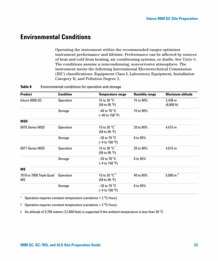
Operating the instrument within the recommended ranges optimizes instrument performance and lifetime. Performance can be affected by sources of heat and cold from heating, air conditioning systems, or drafts. See Table 6. The conditions assume a noncondensing, noncorrosive atmosphere. The instrument meets the following International Electrotechnical Commission (IEC) classifications: Equipment Class I, Laboratory Equipment, Installation Category II, and Pollution Degree 2.
mental conditions for operation and storage
Table 6 EnvironProduct Condition Temperature range Humidity range Maximum altitude
Intuvo 9000 GC Operation 15 to 35 °C (59 to 95 °F)
15 to 90% 2,438 m (8,000 ft)
Storage –40 to 70 °C (–40 to 158 °F)
15 to 90%
MSD
5975 Series MSD Operation 15 to 35 °C * (59 to 95 °F)
20 to 80% 4,615 m
Storage –20 to 70 °C (–4 to 158 °F)
0 to 95%
5977 Series MSD Operation 15 to 35 °C * (59 to 95 °F)
20 to 80% 4,615 m
Storage –20 to 70 °C (–4 to 158 °F)
0 to 95%
MS
7010 or 7000 Triple Quad MS
Operation 15 to 35 °C † (59 to 95 °F)
40 to 80% 5,000 m ‡
Storage –20 to 70 °C (–4 to 158 °F)
0 to 95%
* Operation requires constant temperature (variations < 2 oC/hour)
† Operation requires constant temperature (variations < 2 oC/hour)
‡ An altitude of 3,700 meters (12,000 feet) is supported if the ambient temperature is less than 30 °C
d ALS Site Preparation Guide 23
Intuvo 9000 GC Site Preparation
24
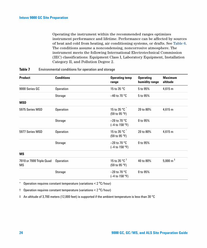
Operating the instrument within the recommended ranges optimizes instrument performance and lifetime. Performance can be affected by sources of heat and cold from heating, air conditioning systems, or drafts. See Table 6. The conditions assume a noncondensing, noncorrosive atmosphere. The instrument meets the following International Electrotechnical Commission (IEC) classifications: Equipment Class I, Laboratory Equipment, Installation Category II, and Pollution Degree 2.
mental conditions for operation and storage
Table 7 EnvironProduct Conditions Operating temp range
Operating humidity range
Maximum altitude
9000 Series GC Operation 15 to 35 °C 5 to 95% 4,615 m
Storage –40 to 70 °C 5 to 95%
MSD
5975 Series MSD Operation 15 to 35 °C * (59 to 95 °F)
20 to 80% 4,615 m
Storage –20 to 70 °C (–4 to 158 °F)
0 to 95%
5977 Series MSD Operation 15 to 35 °C * (59 to 95 °F)
20 to 80% 4,615 m
Storage –20 to 70 °C (–4 to 158 °F)
0 to 95%
MS
7010 or 7000 Triple Quad MS
Operation 15 to 35 °C † (59 to 95 °F)
40 to 80% 5,000 m ‡
Storage –20 to 70 °C (–4 to 158 °F)
0 to 95%
* Operation requires constant temperature (variations < 2 oC/hour)
† Operation requires constant temperature (variations < 2 oC/hour)
‡ An altitude of 3,700 meters (12,000 feet) is supported if the ambient temperature is less than 30 °C
9000 GC, GC/MS, and ALS Site Preparation Guide
Intuvo 9000 GC Site Preparation
Gas Selection
9000 GC, GC/MS, an
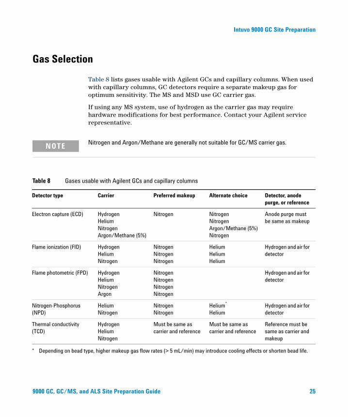
Table 8 lists gases usable with Agilent GCs and capillary columns. When used with capillary columns, GC detectors require a separate makeup gas for optimum sensitivity. The MS and MSD use GC carrier gas.
If using any MS system, use of hydrogen as the carrier gas may require hardware modifications for best performance. Contact your Agilent service representative.
NOTE Nitrogen and Argon/Methane are generally not suitable for GC/MS carrier gas.
sable with Agilent GCs and capillary columns
Table 8 Gases uDetector type Carrier Preferred makeup Alternate choice Detector, anode purge, or reference
Electron capture (ECD) Hydrogen Helium Nitrogen Argon/Methane (5%)
Nitrogen Nitrogen Nitrogen Argon/Methane (5%) Nitrogen
Anode purge must be same as makeup
Flame ionization (FID) Hydrogen Helium Nitrogen
Nitrogen Nitrogen Nitrogen
Helium Helium Helium
Hydrogen and air for detector
Flame photometric (FPD) Hydrogen Helium Nitrogen Argon
Nitrogen Nitrogen Nitrogen Nitrogen
Hydrogen and air for detector
Nitrogen-Phosphorus (NPD)
Helium Nitrogen
Nitrogen Nitrogen
Helium* Helium
Hydrogen and air for detector
Thermal conductivity (TCD)
Hydrogen Helium Nitrogen
Must be same as carrier and reference
Must be same as carrier and reference
Reference must be same as carrier and makeup
* Depending on bead type, higher makeup gas flow rates (> 5 mL/min) may introduce cooling effects or shorten bead life.
d ALS Site Preparation Guide 25
Intuvo 9000 GC Site Preparation
26
WARNING When using hydrogen (H2) as the carrier gas or fuel gas, be aware that hydrogen gas can create a fire hazard. Therefore, be sure that the supply is turned off until the guard chip, column, inlet chip, and other chips are properly installed before supplying hydrogen gas to the instrument.
Hydrogen is flammable. In any application using hydrogen, leak test all connections, lines, and valves before operating the instrument. Always turn off the hydrogen supply at its source before working on the instrument.
Please refer to the safety manual shipped with your instrument.
9000 GC, GC/MS, and ALS Site Preparation Guide
Intuvo 9000 GC Site Preparation
Gas Purity
9000 GC, GC/MS, an
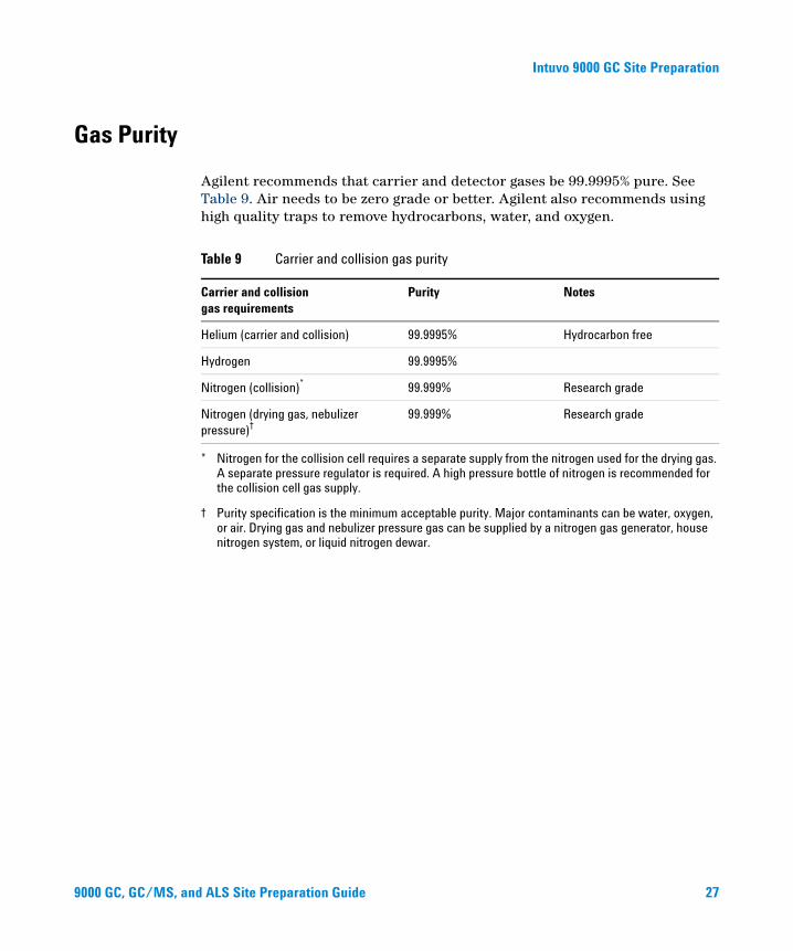
Agilent recommends that carrier and detector gases be 99.9995% pure. See Table 9. Air needs to be zero grade or better. Agilent also recommends using high quality traps to remove hydrocarbons, water, and oxygen.
Table 9 Carrier and collision gas purity
Carrier and collision gas requirements
Purity Notes
Helium (carrier and collision) 99.9995% Hydrocarbon free
Hydrogen 99.9995%
Nitrogen (collision)*
* Nitrogen for the collision cell requires a separate supply from the nitrogen used for the drying gas. A separate pressure regulator is required. A high pressure bottle of nitrogen is recommended for the collision cell gas supply.
99.999% Research grade
Nitrogen (drying gas, nebulizer pressure)†
† Purity specification is the minimum acceptable purity. Major contaminants can be water, oxygen, or air. Drying gas and nebulizer pressure gas can be supplied by a nitrogen gas generator, house nitrogen system, or liquid nitrogen dewar.
99.999% Research grade
d ALS Site Preparation Guide 27
Intuvo 9000 GC Site Preparation
Gas Supplies
General requirements
28
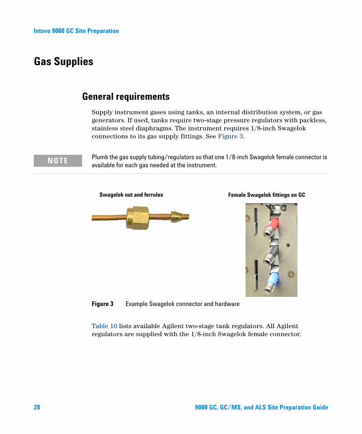
Supply instrument gases using tanks, an internal distribution system, or gas generators. If used, tanks require two-stage pressure regulators with packless, stainless steel diaphragms. The instrument requires 1/8-inch Swagelok connections to its gas supply fittings. See Figure 3.
NOTE Plumb the gas supply tubing/regulators so that one 1/8-inch Swagelok female connector is available for each gas needed at the instrument.
Table 10 lists available Agilent two-stage tank regulators. All Agilent regulators are supplied with the 1/8-inch Swagelok female connector.
Figure 3 Example Swagelok connector and hardware
Swagelok nut and ferrules Female Swagelok fittings on GC
9000 GC, G
C/MS, and ALS Site Preparation Guide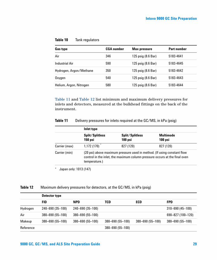
Intuvo 9000 GC Site Preparation
9000 GC, GC/MS, an
Table 11 and Table 12 list minimum and maximum delivery pressures for inlets and detectors, measured at the bulkhead fittings on the back of the instrument.
Table 10 Tank regulators
Gas type CGA number Max pressure Part number
Air 346 125 psig (8.6 Bar) 5183-4641
Industrial Air 590 125 psig (8.6 Bar) 5183-4645
Hydrogen, Argon/Methane 350 125 psig (8.6 Bar) 5183-4642
Oxygen 540 125 psig (8.6 Bar) 5183-4643
Helium, Argon, Nitrogen 580 125 psig (8.6 Bar) 5183-4644
Table 11 Delivery pressures for inlets required at the GC/MS, in kPa (psig)
Inlet type
Split/Splitless 150 psi
Split/Splitless 100 psi
Multimode 100 psi
Carrier (max) 1,172 (170) *
* Japan only: 1013 (147)
827 (120) 827 (120)
Carrier (min) (20 psi) above maximum pressure used in method. (If using constant flow control in the inlet, the maximum column pressure occurs at the final oven temperature.)
m delivery pressures for detectors, at the GC/MS, in kPa (psig)
Table 12 MaximuDetector type
FID NPD TCD ECD FPD
Hydrogen 240–690 (35–100) 240–690 (35–100) 310–690 (45–100)
Air 380–690 (55–100) 380–690 (55–100) 690–827 (100–120)
Makeup 380–690 (55–100) 380–690 (55–100) 380–690 (55–100) 380–690 (55–100) 380–690 (55–100)
Reference 380–690 (55–100)
d ALS Site Preparation Guide 29
Intuvo 9000 GC Site Preparation
30
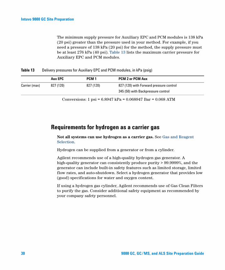
The minimum supply pressure for Auxiliary EPC and PCM modules is 138 kPa (20 psi) greater than the pressure used in your method. For example, if you need a pressure of 138 kPa (20 psi) for the method, the supply pressure must be at least 276 kPa (40 psi). Table 13 lists the maximum carrier pressure for Auxiliary EPC and PCM modules.
Table 13 Delivery pressures for Auxiliary EPC and PCM modules, in kPa (psig)
Aux EPC PCM 1 PCM 2 or PCM Aux
Carrier (max) 827 (120) 827 (120) 827 (120) with Forward pressure control
345 (50) with Backpressure control
Conversions: 1 psi = 6.8947 kPa = 0.068947 Bar = 0.068 ATM
Requirements for hydrogen as a carrier gas
Not all systems can use hydrogen as a carrier gas. See Gas and Reagent Selection.
Hydrogen can be supplied from a generator or from a cylinder.
Agilent recommends use of a high-quality hydrogen gas generator. A high-quality generator can consistently produce purity > 99.9999%, and the generator can include built-in safety features such as limited storage, limited flow rates, and auto-shutdown. Select a hydrogen generator that provides low (good) specifications for water and oxygen content.
If using a hydrogen gas cylinder, Agilent recommends use of Gas Clean Filters to purify the gas. Consider additional safety equipment as recommended by your company safety personnel.
9000 GC, GC/MS, and ALS Site Preparation Guide
Intuvo 9000 GC Site Preparation
GC/MS Gas Requirements
9000 GC, GC/MS, an
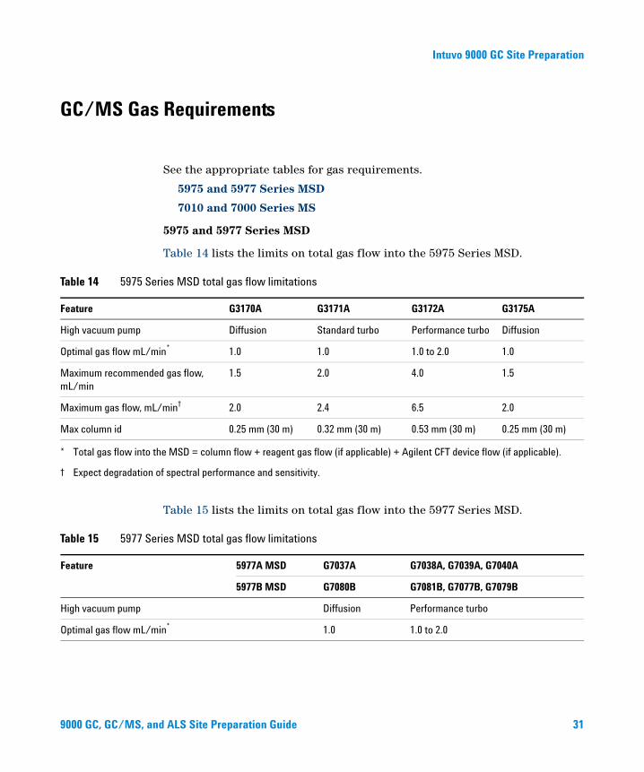
See the appropriate tables for gas requirements.
5975 and 5977 Series MSD
7010 and 7000 Series MS
5975 and 5977 Series MSD
Table 14 lists the limits on total gas flow into the 5975 Series MSD.
Table 14 5975 Series MSD total gas flow limitations
Feature G3170A G3171A G3172A G3175A
High vacuum pump Diffusion Standard turbo Performance turbo Diffusion
Optimal gas flow mL/min* 1.0 1.0 1.0 to 2.0 1.0
Maximum recommended gas flow, mL/min
1.5 2.0 4.0 1.5
Maximum gas flow, mL/min† 2.0 2.4 6.5 2.0
Max column id 0.25 mm (30 m) 0.32 mm (30 m) 0.53 mm (30 m) 0.25 mm (30 m)
* Total gas flow into the MSD = column flow + reagent gas flow (if applicable) + Agilent CFT device flow (if applicable).
† Expect degradation of spectral performance and sensitivity.
Table 15 lists the limits on total gas flow into the 5977 Series MSD.
ries MSD total gas flow limitations
Table 15 5977 SeFeature 5977A MSD G7037A G7038A, G7039A, G7040A
5977B MSD G7080B G7081B, G7077B, G7079B
High vacuum pump Diffusion Performance turbo
Optimal gas flow mL/min* 1.0 1.0 to 2.0
d ALS Site Preparation Guide 31
Intuvo 9000 GC Site Preparation
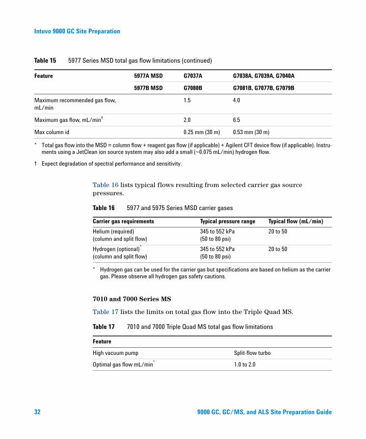
Maximum recommended gas flow, mL/min
1.5 4.0
Maximum gas flow, mL/min† 2.0 6.5
Max column id 0.25 mm (30 m) 0.53 mm (30 m)
* Total gas flow into the MSD = column flow + reagent gas flow (if applicable) + Agilent CFT device flow (if applicable). Instru-ments using a JetClean ion source system may also add a small (~0.075 mL/min) hydrogen flow.
† Expect degradation of spectral performance and sensitivity.
Table 15 5977 Series MSD total gas flow limitations (continued)
Feature 5977A MSD G7037A G7038A, G7039A, G7040A
5977B MSD G7080B G7081B, G7077B, G7079B
32
Table 16 lists typical flows resulting from selected carrier gas source pressures.
7010 and 7000 Series MS
Table 17 lists the limits on total gas flow into the Triple Quad MS.
Table 16 5977 and 5975 Series MSD carrier gases
Carrier gas requirements Typical pressure range Typical flow (mL/min)
Helium (required) (column and split flow)
345 to 552 kPa (50 to 80 psi)
20 to 50
Hydrogen (optional)* (column and split flow)
* Hydrogen gas can be used for the carrier gas but specifications are based on helium as the carrier gas. Please observe all hydrogen gas safety cautions.
345 to 552 kPa (50 to 80 psi)
20 to 50
Table 17 7010 and 7000 Triple Quad MS total gas flow limitations
Feature
High vacuum pump Split-flow turbo
Optimal gas flow mL/min* 1.0 to 2.0
9000 GC, GC/MS, and ALS Site Preparation Guide
Intuvo 9000 GC Site Preparation
9000 GC, GC/MS, an
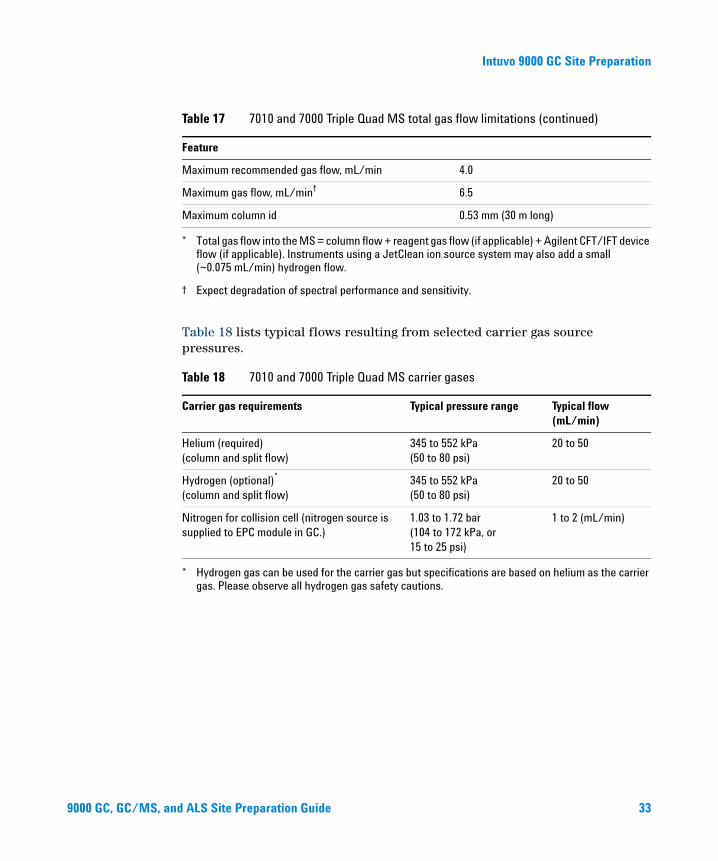
Table 18 lists typical flows resulting from selected carrier gas source pressures.
Maximum recommended gas flow, mL/min 4.0
Maximum gas flow, mL/min† 6.5
Maximum column id 0.53 mm (30 m long)
* Total gas flow into the MS = column flow + reagent gas flow (if applicable) + Agilent CFT/IFT device flow (if applicable). Instruments using a JetClean ion source system may also add a small (~0.075 mL/min) hydrogen flow.
† Expect degradation of spectral performance and sensitivity.
Table 18 7010 and 7000 Triple Quad MS carrier gases
Carrier gas requirements Typical pressure range Typical flow (mL/min)
Helium (required) (column and split flow)
345 to 552 kPa (50 to 80 psi)
20 to 50
Hydrogen (optional)* (column and split flow)
* Hydrogen gas can be used for the carrier gas but specifications are based on helium as the carrier gas. Please observe all hydrogen gas safety cautions.
345 to 552 kPa (50 to 80 psi)
20 to 50
Nitrogen for collision cell (nitrogen source is supplied to EPC module in GC.)
1.03 to 1.72 bar (104 to 172 kPa, or 15 to 25 psi)
1 to 2 (mL/min)
Table 17 7010 and 7000 Triple Quad MS total gas flow limitations (continued)
Feature
d ALS Site Preparation Guide 33
Intuvo 9000 GC Site Preparation
Gas Plumbing
34
WARNING All compressed gas cylinders should be securely fastened to an immovable structure or permanent wall. Compressed gases should be stored and handled in accordance with the relevant safety codes.
Gas cylinders should not be located in the path of heated oven exhaust.
To avoid possible eye injury, wear eye protection when using compressed gas.
9000 GC, GC/MS, and ALS Site Preparation Guide
Intuvo 9000 GC Site Preparation
9000 GC, GC/MS, an
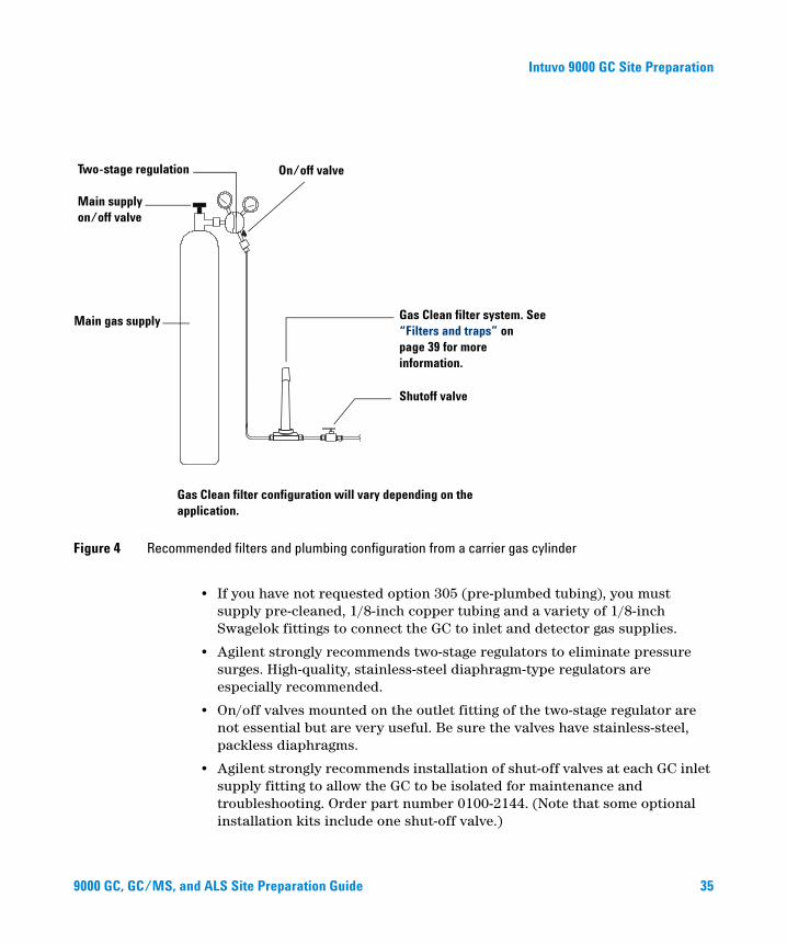
Figure 4 Recommended filters and plumbing configuration from a carrier gas cylinder
Two-stage regulation
Main supply on/off valve
Main gas supply
On/off valve
Gas Clean filter system. See “Filters and traps” on page 39 for more information.
Shutoff valve
Gas Clean filter configuration will vary depending on the application.
• If you have not requested option 305 (pre-plumbed tubing), you must supply pre-cleaned, 1/8-inch copper tubing and a variety of 1/8-inch Swagelok fittings to connect the GC to inlet and detector gas supplies.
• Agilent strongly recommends two-stage regulators to eliminate pressure surges. High-quality, stainless-steel diaphragm-type regulators are especially recommended.
• On/off valves mounted on the outlet fitting of the two-stage regulator are not essential but are very useful. Be sure the valves have stainless-steel, packless diaphragms.
• Agilent strongly recommends installation of shut-off valves at each GC inlet supply fitting to allow the GC to be isolated for maintenance and troubleshooting. Order part number 0100-2144. (Note that some optional installation kits include one shut-off valve.)
d ALS Site P
reparation Guide 35
Intuvo 9000 GC Site Preparation
36
• If you purchased automated valving, the valve actuation requires a separate pressurized, dry air supply at 380 kPa (55 psig). This air supply must end in a male fitting compatible with a 1/4-inch id plastic tube at the GC.
• FID, FPD, and NPD detectors require a dedicated air supply. Operation may be affected by pressure pulses in air lines shared with other devices.
• Flow- and pressure-controlling devices require at least 10 psi (138 kPa) pressure differential across them to operate properly. Set source pressures and capacities high enough to ensure this.
• Situate auxiliary pressure regulators close to the GC inlet fittings. This ensures that the supply pressure is measured at the instrument (rather than at the source); pressure at the source may be different if the gas supply lines are long or narrow.
• Never use liquid thread sealer to connect fittings.
• Never use chlorinated solvents to clean tubing or fittings.
Supply tubing for most carrier and detector gases
Use only preconditioned copper tubing (part number 5180-4196) to supply gases to the instrument. Do not use ordinary copper tubing—it contains oils and contaminants.
Do not use methylene chloride or other halogenated solvent to clean tubing that will be
CAUTIONused with an electron capture detector. They will cause elevated baselines and detector noise until they are completely flushed out of the system.Do not use plastic tubing for suppling detector and inlet gases to the GC. It is
CAUTIONpermeable to oxygen and other contaminants that can damage columns and detectors.Plastic tubing can melt if near hot exhaust or components.
The tubing diameter depends on the distance between the supply gas and the GC and the total flow rate for the particular gas. Tubing of 1/8-in diameter is adequate when the supply line is less than 15 feet (4.6 m) long.
9000 GC, GC/MS, and ALS Site Preparation Guide
Intuvo 9000 GC Site Preparation
9000 GC, GC/MS, an
Use larger diameter tubing (1/4-in) for distances greater then 15 feet (4.6 m) or when multiple instruments are connected to the same source. Use larger diameter tubing if high demand is anticipated (for example, air for an FID).
Be generous when cutting tubing for local supply lines—a coil of flexible tubing between the supply and the instrument lets you move the GC without moving the gas supply. Take this extra length into account when choosing the tubing diameter.
Supply tubing for hydrogen gas
Agilent recommends using new chromatographic quality stainless steel tubing and fittings when using hydrogen.
• Do not re-use old tubing when installing or switching to hydrogen supply lines for carrier gas or the JetClean ion source system. Hydrogen gas tends to remove contaminants left on old tubing by previous gases (by helium, for example). These contaminants can appear in output as high background noise or hydrocarbon contamination for several weeks.
• Especially do not use old copper tubing, which can become brittle.
WARNING Do not use old copper tubing with hydrogen gas. Old copper tubing can become brittle and create a safety hazard.
d ALS Site Preparation Guide 37
Intuvo 9000 GC Site Preparation
Two-stage pressure regulators
38
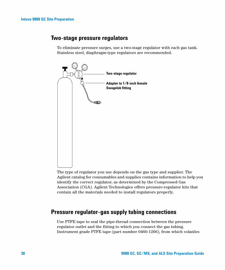
To eliminate pressure surges, use a two-stage regulator with each gas tank. Stainless steel, diaphragm-type regulators are recommended.
The type of regulator you use depends on the gas type and supplier. The Agilent catalog for consumables and supplies contains information to help you identify the correct regulator, as determined by the Compressed Gas Association (CGA). Agilent Technologies offers pressure-regulator kits that contain all the materials needed to install regulators properly.
Two-stage regulator
Adapter to 1/8-inch female Swagelok fitting
Pressure regulator-gas supply tubing connections
Use PTFE tape to seal the pipe-thread connection between the pressure regulator outlet and the fitting to which you connect the gas tubing. Instrument grade PTFE tape (part number 0460-1266), from which volatiles
9000 GC, GC/MS, and ALS Site Preparation Guide
Intuvo 9000 GC Site Preparation
9000 GC, GC/MS, an
have been removed, is recommended for all fittings. Do not use pipe dope to seal the threads; it contains volatile materials that will contaminate the tubing.
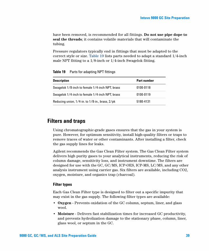
Pressure regulators typically end in fittings that must be adapted to the correct style or size. Table 19 lists parts needed to adapt a standard 1/4-inch male NPT fitting to a 1/8-inch or 1/4-inch Swagelok fitting.
Table 19 Parts for adapting NPT fittings
Description Part number
Swagelok 1/8-inch to female 1/4-inch NPT, brass 0100-0118
Swagelok 1/4-inch to female 1/4-inch NPT, brass 0100-0119
Reducing union, 1/4-in. to 1/8-in., brass, 2/pk 5180-4131
Filters and traps
Using chromatographic-grade gases ensures that the gas in your system is pure. However, for optimum sensitivity, install high-quality filters or traps to remove traces of water or other contaminants. After installing a filter, check the gas supply lines for leaks.
Agilent recommends the Gas Clean Filter system. The Gas Clean Filter system delivers high purity gases to your analytical instruments, reducing the risk of column damage, sensitivity loss, and instrument downtime. The filters are designed for use with the GC, GC/MS, ICP-OES, ICP-MS, LC/MS, and any other analysis instrument using carrier gas. Six filters are available, including CO2, oxygen, moisture, and organics trap (charcoal).
Filter types
Each Gas Clean Filter type is designed to filter out a specific impurity that may exist in the gas supply. The following filter types are available:
• Oxygen - Prevents oxidation of the GC column, septum, liner, and glass wool.
• Moisture - Delivers fast stabilization times for increased GC productivity, and prevents hydrolization damage to the stationary phase, column, liner, glass wool, or septum in the GC.
d ALS Site Preparation Guide 39
Intuvo 9000 GC Site Preparation
40
• Process Moisture - Prevents oxidation of GC components and is safe to use with acetylene in process GC applications.
• Charcoal - Removes organic compounds and ensures correct performance of FID detectors in the GC.
• GC/MS - Delivers fast stabilization times for increased GC productivity, removes oxygen, moisture, and hydrocarbons from the carrier gas for MS applications, and provides ultimate GC column protection.
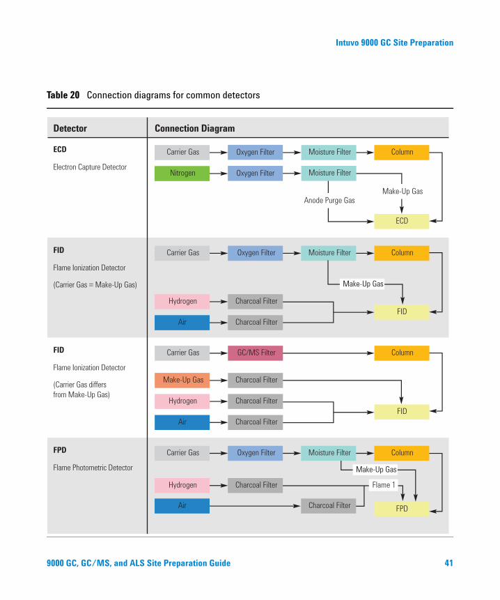
Table 20 on page 41 shows recommended filter connection diagrams for common instrument configurations.
9000 GC, GC/MS, and ALS Site Preparation Guide
Intuvo 9000 GC Site Preparation
9000 GC, GC/MS, an
Table 20 Connection diagrams for common detectors
ECD
Electron Capture Detector
Carrier Gas
Nitrogen
Oxygen Filter
Oxygen Filter
Column
ECD
Make-Up GasAnode Purge Gas
Moisture Filter
Moisture Filter
FID
Flame Ionization Detector
(Carrier Gas = Make-Up Gas)
Carrier Gas
Hydrogen
Air
Oxygen Filter Moisture Filter
FID
Charcoal Filter
Charcoal Filter
Column
Make-Up Gas
FID
Flame Ionization Detector
(Carrier Gas differs
from Make-Up Gas)
Carrier Gas
Make-Up Gas
Hydrogen
Air
GC/MS Filter
Charcoal Filter
FID
Charcoal Filter
Charcoal Filter
Column
FPD
Flame Photometric Detector
Carrier Gas
Hydrogen
Air
Oxygen Filter Moisture Filter
FPD
Column
Charcoal Filter
Charcoal Filter Flame 1
Make-Up Gas
Detector Connection Diagram
d ALS Site Preparation Guide 41

Intuvo 9000 GC Site Preparation
Table 20 Connection diagrams for common detectors (continued)
MS (MSD)
Mass Selective Detector
Carrier Gas Oxygen Filter Moisture Filter Column
MS
Carrier Gas GC/MS Filter Column
MS
NPD
Nitrogen-Phosphorous Detector
(Carrier Gas = Make-Up Gas)
Carrier Gas
Hydrogen
Air
Oxygen Filter
Charcoal Filter
Charcoal Filter
Column
NPD
Make-Up Gas
Moisture Filter
TCD
Thermal Conductivity Detector
Carrier Gas Oxygen Filter Moisture Filter Column
TCD
Reference Channel
Make-Up Gas, if necessary
Detector Connection Diagram
42
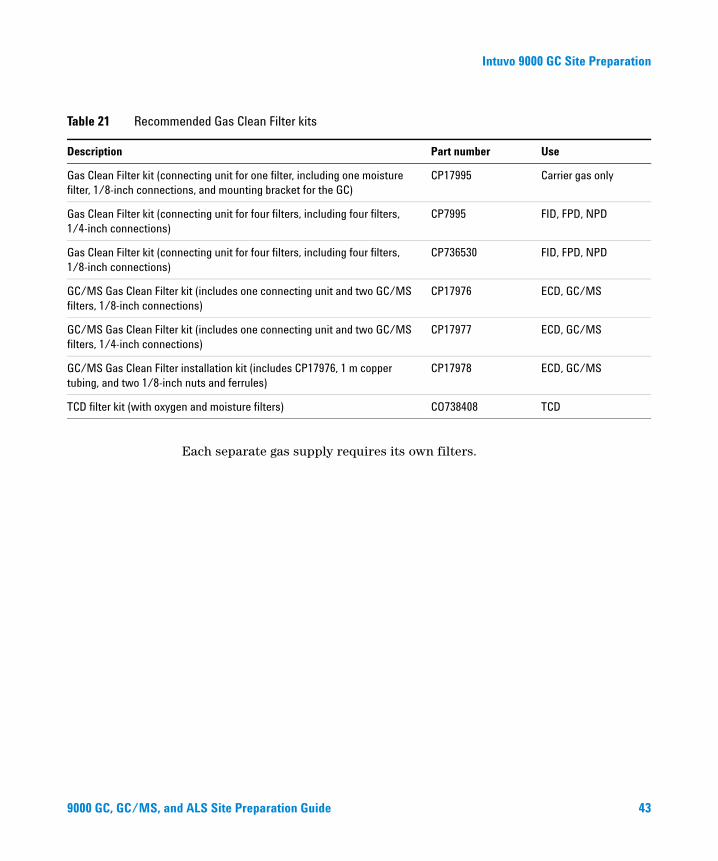
Table 21 lists the most common Gas Clean Filter system kits. See the Agilent online store or contact your local Agilent sales representative for additional filters, parts, and accessories applicable to your instrument configuration.
9000 GC, GC/MS, and ALS Site Preparation Guide
Intuvo 9000 GC Site Preparation
9000 GC, GC/MS, an
ended Gas Clean Filter kits
Table 21 RecommDescription Part number Use
Gas Clean Filter kit (connecting unit for one filter, including one moisture filter, 1/8-inch connections, and mounting bracket for the GC)
CP17995 Carrier gas only
Gas Clean Filter kit (connecting unit for four filters, including four filters, 1/4-inch connections)
CP7995 FID, FPD, NPD
Gas Clean Filter kit (connecting unit for four filters, including four filters, 1/8-inch connections)
CP736530 FID, FPD, NPD
GC/MS Gas Clean Filter kit (includes one connecting unit and two GC/MS filters, 1/8-inch connections)
CP17976 ECD, GC/MS
GC/MS Gas Clean Filter kit (includes one connecting unit and two GC/MS filters, 1/4-inch connections)
CP17977 ECD, GC/MS
GC/MS Gas Clean Filter installation kit (includes CP17976, 1 m copper tubing, and two 1/8-inch nuts and ferrules)
CP17978 ECD, GC/MS
TCD filter kit (with oxygen and moisture filters) CO738408 TCD
Each separate gas supply requires its own filters.
d ALS Site Preparation Guide 43
Intuvo 9000 GC Site Preparation
Cryogenic Cooling Requirements
44
Cryogenic cooling allows you to cool the inlet, including cooling to setpoints below ambient temperature. A solenoid valve controls the flow of coolant. The oven can use either liquid carbon dioxide (CO2) or liquid nitrogen (N2) as a coolant.
N2 coolant requires different hardware on the GC. You can use air cooling on a multimode inlet with the N2 solenoid valves and hardware.
Using carbon dioxide
Pressurized liquid CO is a hazardous material. Take precautions to protect
WARNING 2personnel from high pressures and low temperatures. CO2 in high concentrations is toxic to humans; take precautions to prevent hazardous concentrations. Consult your local supplier for recommended safety precautions and delivery system design.Liquid CO2 is available in high-pressure tanks containing liquid. The CO2 should be free of particulate material, oil, and other contaminants. These contaminants could clog the expansion orifice or affect the proper operation of the GC.
Do not use copper tubing or thin-wall stainless steel tubing with liquid CO . Both
WARNING 2harden at stress points and may explode.Additional requirements for the liquid CO2 system include:
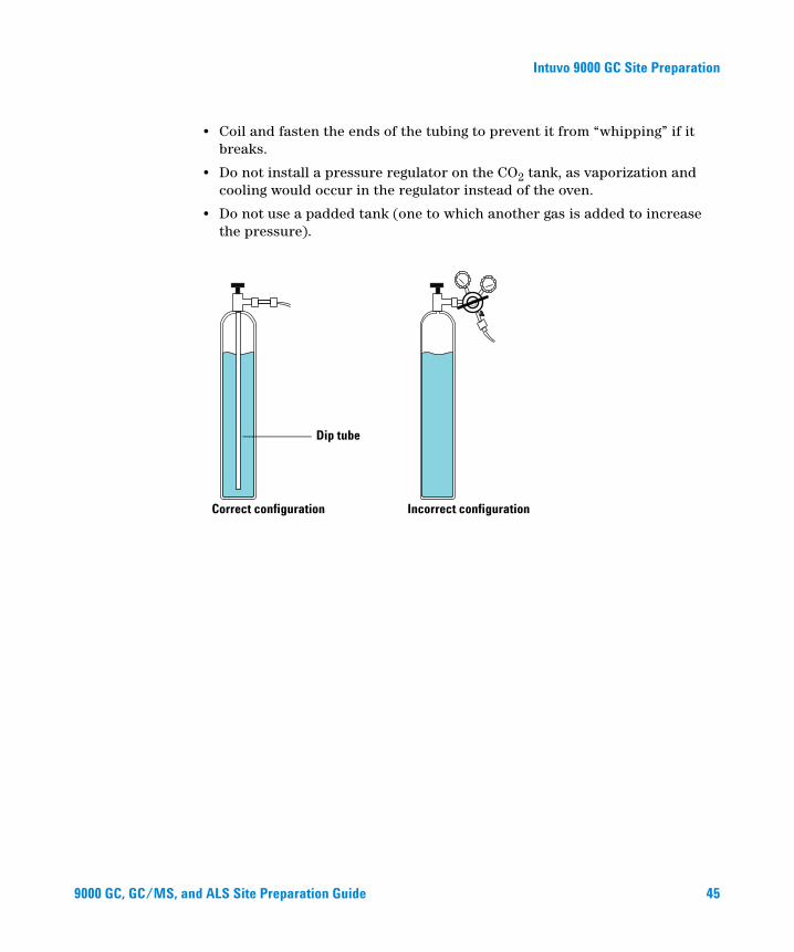
• The tank must have an internal dip tube or eductor tube to deliver liquid CO2 instead of gas (see the figure below).
• Typical liquid CO2 tank pressure will be 4830 to 6900 kPa (700 to 1,000 psi) at a temperature of 25 °C.
• Use 1/8-inch diameter heavy-wall stainless steel tubing for supply tubing. The tubing should be between 1.5 and 15 m (5 and 50 feet) long. (Agilent part number 7157-0210, 20 ft)
9000 GC, GC/MS, and ALS Site Preparation Guide
Intuvo 9000 GC Site Preparation
9000 GC, GC/MS, an
• Coil and fasten the ends of the tubing to prevent it from “whipping” if it breaks.
• Do not install a pressure regulator on the CO2 tank, as vaporization and cooling would occur in the regulator instead of the oven.
• Do not use a padded tank (one to which another gas is added to increase the pressure).
Dip tube
Correct configuration Incorrect configuration
d ALS Site Prepara
tion Guide 45
Intuvo 9000 GC Site Preparation
Using liquid nitrogen
46
Liquid nitrogen is a hazard because of the extremely low temperatures and high
WARNINGpressures that may occur in improperly designed supply systems.Liquid nitrogen can present an asphyxiant hazard if vaporizing nitrogen displaces oxygen in the air. Consult local suppliers for safety precautions and design information.
Liquid nitrogen is supplied in insulated Dewar tanks. The correct type for cooling purposes is a low-pressure Dewar equipped with a dip tube—to deliver liquid rather than gas—and a safety relief valve to prevent pressure build-up. The relief valve is set by the supplier at 138 to 172 kPa (20 to 25 psi).
If liquid nitrogen is trapped between a closed tank valve and the cryo valve on the
WARNINGGC, tremendous pressure will develop and may cause an explosion. For this reason, keep the delivery valve on the tank open so that the entire system is protected by the pressure relief valve.To move or replace a tank, close the delivery valve and carefully disconnect the line at either end to let residual nitrogen escape.
Additional requirements for the liquid N2 system include:
• Cryogenic cooling with Liquid N2 requires 1/4-inch insulated copper tubing.
• Make sure the supply tubing for liquid N2 is insulated. Foam tubing used for refrigeration and air-conditioning lines is suitable for insulation. (Foam tubing insulation is not supplied by Agilent. Contact a local supplier.) Since pressures are low, insulated copper tubing is adequate.
• Situate the liquid nitrogen tank close (within 1.5 to 3 m, or 5 to 10 feet) to the GC to ensure that liquid, not gas, is supplied to the inlet.
9000 GC, GC/MS, and ALS Site Preparation Guide
Intuvo 9000 GC Site Preparation
Using compressed air
9000 GC, GC/MS, an
The multimode inlet can also use compressed air cooling with the liquid N2 inlet cooling option. Requirements for compressed air cooling:
• The compressed air should be free of particulate material, oil, and other contaminants. These contaminants could clog the inlet’s cryo value or impact the proper operation of the GC.
• For a multimode inlet with N2 cooling, set the air supply pressure to 138 to 208 kPa (20 and 30 psig).
While air supplied from tanks can meet these criteria, the consumption rate of air can be 80 L/min, varying based on supply pressure.
Installation of a compressed air line to the inlet cryo coolant valve requires the hardware (and appropriate fittings) noted below:
• Use 1/4-inch copper or stainless steel tubing for supply tubing to the N2 valve
d ALS Site Preparation Guide 47
Intuvo 9000 GC Site Preparation
Maximum Length of Cables and Hoses
48
The distance between system modules may be limited by some of the cabling and the vent or vacuum hoses.
• The length of the Agilent-supplied remote cable is 2 meters (6.6 feet).
• The length of the Agilent-supplied LAN cable is 10 meters (32.8 feet).
• The lengths of the power cords are 2 meters (6.6 feet).
• A quadrupole GC/MS system foreline pump can be located on the laboratory bench or on the floor. It must be close to the MS because it is connected by a hose. The hose is stiff and cannot be bent sharply. The length of the vacuum hose is 130 cm (4.24 feet) from the high vacuum pump to the foreline pump, while the length of the foreline pump power cord is 2 meters (6.6 feet).
9000 GC, GC/MS, and ALS Site Preparation Guide
Intuvo 9000 GC Site Preparation
Site LAN Network
9000 GC, GC/MS, an
If you intend to connect your system to your site’s LAN network, you must have an additional shielded twisted pair network cable (8121-0940).
NOTE Agilent Technologies is not responsible for connecting to or establishing communication with your site LAN network. The representative will test the system’s ability to communicate on a mini-hub or LAN switch only.
NOTE The IP addresses assigned to the instrument(s) must be fixed (permanently assigned) addresses. If you intend to connect your system to your site’s network, each piece of equipment must have a unique, fixed (static) IP address assigned to it.
NOTE For a Single Quad GC/MS system, Agilent recommends, sells, and supports the use of a PC with one (1) network interface card (NIC) and a network switch to isolate the GC/MS system from the site LAN. The network switch supplied with Agilent systems prevents instrument-to-PC network traffic from entering the site LAN and keeps site LAN network traffic from interfering with instrument-to-PC communications. Agilent develops and tests all Single Quad GC/MS hardware and software using the single NIC configuration and has no known network configuration issues. Alternate network configurations can be configured and managed by the end user at their own risk and expense.
NOTE For Triple Quad GC/MS systems, Agilent recommends, sells, and supports the use of a PC with two network interface cards (NIC) to provide both a site LAN connection and an isolated GC/MS system connection. Agilent develops and tests all Triple Quad GC/MS hardware and software using the dual NIC configuration, and has no known network configuration issues. Alternate network configurations can be configured and managed by the end user at their own risk and expense.
d ALS Site Preparation Guide 49

Intuvo 9000 GC Site Preparation
50
9000 GC, GC/MS, and ALS Site Preparation Guide
Intuvo 9000 GC Site Preparation
PC Requirements
9000 GC, GC/MS, an
If using an Agilent data system, refer to the data system documentation for PC requirements.
d ALS Site Preparation Guide 51

Intuvo 9000 GC Site Preparation
52
9000 GC, GC/MS, and ALS Site Preparation Guide
GC, GC/MS, and ALSSite Preparation Guide
27693A and 7650 Automatic Liquid Sampler Site Preparation
Customer Responsibilities 54
Basic Tools and Consumable Supplies 55
Dimensions and Weight 56
Power Consumption 57
Environmental Conditions 57
Chiller Supplies 58
This section outlines the space and resource requirements for a 7693A and 7650 automatic liquid sampler (ALS). For a successful and timely installation of the ALS, the site must meet these requirements before beginning installation. Necessary supplies (operating supplies, consumables, and other usage-dependent items such as vials, syringes, and solvents) must also be available. Refer to the Agilent Web site at www.agilent.com/chem for the most up-to-date listing of GC, GC/MS, and ALS supplies and consumables.
Refer to your GC documentation for compatibility with a specific ALS model.
53Agilent Technologies

7693A and 7650 Automatic Liquid Sampler Site Preparation
Customer Responsibilities
54
The specifications in this manual outline the necessary space, electrical outlets, tubing, operating supplies, consumables, and other usage-dependent items such as vials, syringes, and solvents required for the successful installation of instruments and systems.
If Agilent is delivering installation and familiarization services, users of the instrument should be present throughout these services; otherwise, they will miss important operational, maintenance, and safety information.
If Agilent is delivering installation and familiarization services, delays due to inadequate site preparation could cause loss of instrument use during the warranty period. In extreme cases, Agilent Technologies may ask to be reimbursed for the additional time required to complete the installation. Agilent Technologies provides service during the warranty period and under maintenance agreements only if the specified site requirements are met.
GC, GC/MS, and ALS Site Preparation Guide
7693A and 7650 Automatic Liquid Sampler Site Preparation
Basic Tools and Consumable Supplies
GC, GC/MS, and AL
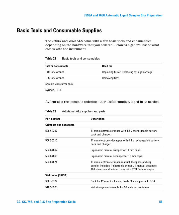
The 7693A and 7650 ALS come with a few basic tools and consumables depending on the hardware that you ordered. Below is a general list of what comes with the instrument.
Agilent also recommends ordering other useful supplies, listed in as needed.
Table 22 Basic tools and consumables
Tool or consumable Used for
T10 Torx wrench Replacing turret. Replacing syringe carriage.
T35 Torx wrench Removing tray.
Sample vial starter pack
Syringe, 10 µL
Table 23 Additional ALS supplies and parts
Part number Description
Crimpers and decappers
5062-0207 11 mm electronic crimper with 4.8 V rechargeable battery pack and charger.
5062-0210 11 mm electronic decapper with 4.8 V rechargeable battery pack and charger.
5040-4667 Ergonomic manual crimper for 11 mm caps.
5040-4668 Ergonomic manual decapper for 11 mm caps.
5040-4674 11 mm electronic crimper, manual decapper, and cap bundle. Includes 1 electronic crimper, 1 manual decapper, 100 silvertone aluminum caps with PTFE/rubber septa.
Vial racks (7693A)
9301-0722 Rack for 12 mm, 2 mL vials, holds 50 vials per rack. 5/pk.
5182-0575 Vial storage container, holds 50 vials per container.
S Site Preparation Guide 55
7693A and 7650 Automatic Liquid Sampler Site Preparation
Dimensions and Weight
56
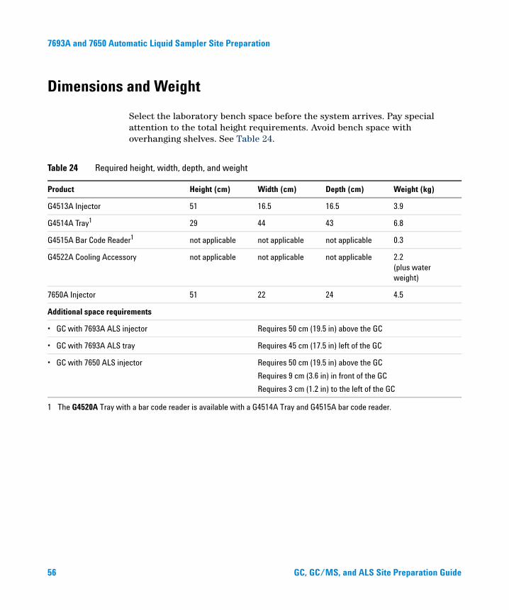
Select the laboratory bench space before the system arrives. Pay special attention to the total height requirements. Avoid bench space with overhanging shelves. See Table 24.
Table 24 Required height, width, depth, and weight
Product Height (cm) Width (cm) Depth (cm) Weight (kg)
G4513A Injector 51 16.5 16.5 3.9
G4514A Tray1 29 44 43 6.8
G4515A Bar Code Reader1 not applicable not applicable not applicable 0.3
G4522A Cooling Accessory not applicable not applicable not applicable 2.2 (plus water weight)
7650A Injector 51 22 24 4.5
Additional space requirements
• GC with 7693A ALS injector Requires 50 cm (19.5 in) above the GC
• GC with 7693A ALS tray Requires 45 cm (17.5 in) left of the GC
• GC with 7650 ALS injector Requires 50 cm (19.5 in) above the GC
Requires 9 cm (3.6 in) in front of the GC
Requires 3 cm (1.2 in) to the left of the GC
1 The G4520A Tray with a bar code reader is available with a G4514A Tray and G4515A bar code reader.
GC, GC/MS, and ALS Site Preparation Guide
7693A and 7650 Automatic Liquid Sampler Site Preparation
Power Consumption
GC, GC/MS, and AL
The ALS components draw power from the GC. No other power source is required.
Environmental Conditions
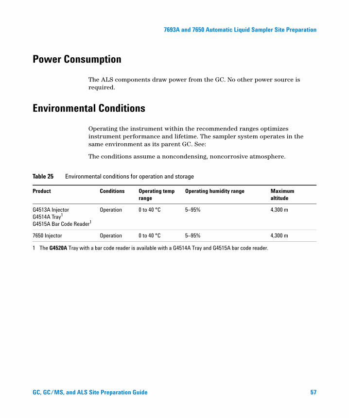
Operating the instrument within the recommended ranges optimizes instrument performance and lifetime. The sampler system operates in the same environment as its parent GC. See:
The conditions assume a noncondensing, noncorrosive atmosphere.
Table 25 Environmental conditions for operation and storage
Product Conditions Operating temp range
Operating humidity range Maximum altitude
G4513A Injector G4514A Tray1 G4515A Bar Code Reader1
Operation 0 to 40 °C 5–95% 4,300 m
7650 Injector Operation 0 to 40 °C 5–95% 4,300 m
1 The G4520A Tray with a bar code reader is available with a G4514A Tray and G4515A bar code reader.
S Site Preparation Guide 57
Agilent Technologies
Chiller Supplies
If using the optional G4522A Cooling Accessory, you will need to supply:
• A water chiller
• Tubing and 1/8-inch Swagelok fittings to connect the chilled water and return water to the chiller
• A container or drain to dispose of condensate from the tray
Agilent Technologies, Inc.
Printed in USA, March 2001