Control Systems in Biopharma Applications - Pharma Manufacturing · Control systems in Biopharma...
19
SPONSORED BY WWW.PHARMAMANUFACTURING.COM SPECIAL REPORT Control Systems in Biopharma Applications
Transcript of Control Systems in Biopharma Applications - Pharma Manufacturing · Control systems in Biopharma...
sponsored by
WWW.PHARMAMANUFACTURING.COM
Special RepoRt
Control Systems in Biopharma Applications
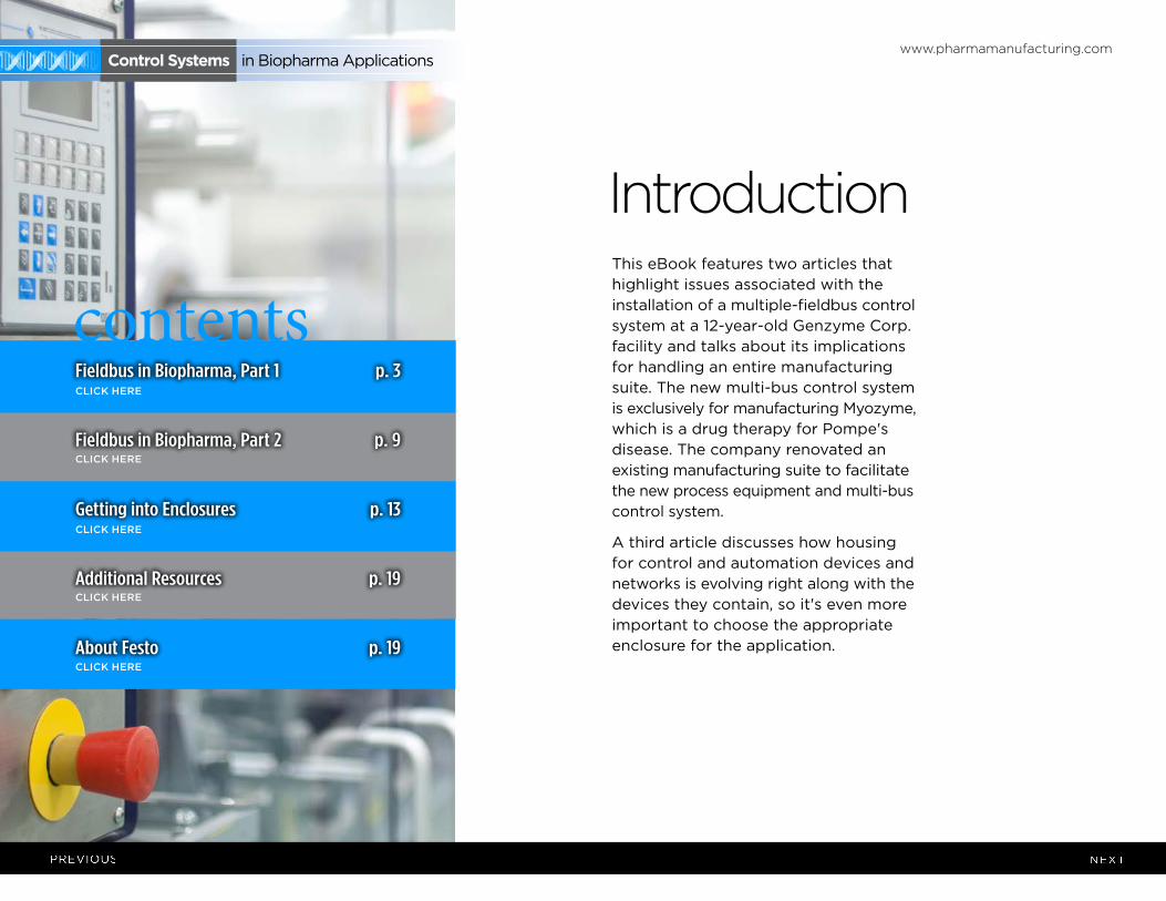
introductionThis eBook features two articles that highlight issues associated with the installation of a multiple-fieldbus control system at a 12-year-old Genzyme Corp. facility and talks about its implications for handling an entire manufacturing suite. The new multi-bus control system is exclusively for manufacturing Myozyme, which is a drug therapy for Pompe's disease. The company renovated an existing manufacturing suite to facilitate the new process equipment and multi-bus control system.
A third article discusses how housing for control and automation devices and networks is evolving right along with the devices they contain, so it's even more important to choose the appropriate enclosure for the application.
www.pharmamanufacturing.com
contents
Control systems in Biopharma Applications
Fieldbus in Biopharma, Part 1 p. 3
Fieldbus in Biopharma, Part 2 p. 9
Getting into Enclosures p. 13
Additional Resources p. 19
About Festo p. 19
click here
click here
click here
click here
click here
www.pharmamanufacturing.com Control systems in Biopharma Applications
Genzyme Corp. recently installed a multiple-fieldbus control system platform at its pharmaceutical manufacturing facility in Allston, Mass. This plant produces enzyme-replacement therapies for rare lysosomal storage disorders (LSDs), which are classified as orphan diseases. The Allston site was built approximately 12 years ago with a conventional distributed control system (DCS) that’s used for manufacturing two enzyme replacement therapies. These drugs include Cerezyme for Gaucher’s disease and Fabryzyme for Fabry’s disease.
The new multi-bus control system is exclusively for manufacturing Myozyme, which is a drug therapy for Pompe’s disease. We renovated an existing manufacturing suite to facilitate the new process equipment and multi-bus control system.
Process areas included in the multi-bus control system include mammalian
cell culture, purification, clean-in-place (CIP) and steam-in-place (SIP). Bus technology has been deployed on skid equipment, which includes bioreactor skids, chromatography skids, ultra-filtration skids, and CIP skids. Also, bus technology has been deployed on stick-built fixed vessels, associated piping, and transfer panels. Fieldbus protocols included in the facility are Foundation fieldbus, Profibus-DP, AS-interface (AS-i), and DeviceNet.
This was our first introduction to bus technology at Genzyme, and our subsequent selection of fieldbus technologies was based on the process equipment needs in a cell culture and protein purification manufacturing environment. We use fielbuses in process areas, which are electrically-rated as general purpose and Class 1, Division 2. This article highlights issues associated with using bus technology in each of these areas. We’ll also talk about fieldbus implications for facility constructability,
software design, commissioning, metrology and calibration, validation, and maintenance.
WhiCh Fieldbus Where?During the preliminary design phase for building the new Myozyme manufacturing suite, we asked our design team, which included Genzyme personnel, a systems integrator, and
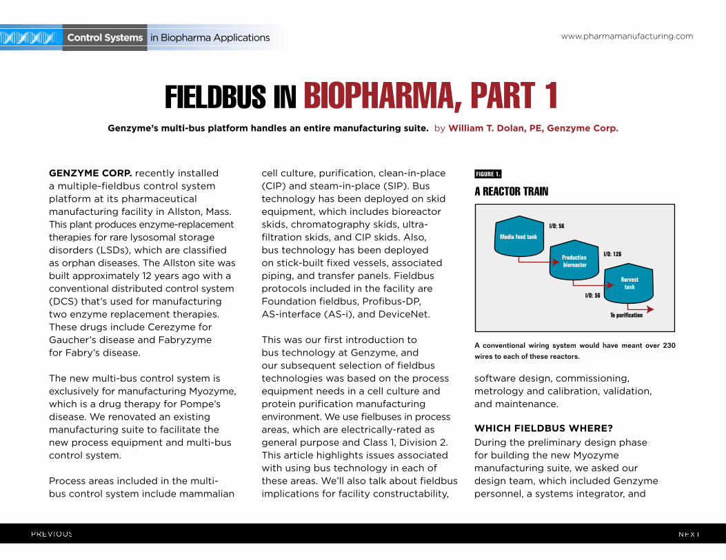
A REACTOR TRAIN
A conventional wiring system would have meant over 230 wires to each of these reactors.
fIguRE 1.
Harvesttank
I/O: 56
I/O: 126
I/O: 56
Production bioreactor
Media feed tank
To purification
FTB-B4
FTB-B3
FTB-B2
Level 3M
Level 3
Level 2M
Level 2
Controller Cabinet
FTB-B1productionbioreactor
FF
FF
FF
FF
ASI
ASI
ASI
ASI
PB
Motor controlcenterDN1 Cable
Level 1M
Level 2
Conventional: 238 cablesFieldbus: 14 cables
Stick-builtvessels
Skid equipment
No cross-over between segments on skid equipment
versus stick-built.
FF: Foundation FieldbusAS-I: Actuator Sensor Interface Bus
PB: Profibus-DPDN: DeviceNet
Control systems in Biopharma Applications
Genzyme’s multi-bus platform handles an entire manufacturing suite. by William T. dolan, pe, Genzyme Corp.
fIEldbus IN bIOphARmA, pART 1
www.pharmamanufacturing.com Control systems in Biopharma Applications
our construction/engineering firm, to evaluate fieldbus as a viable technology. We felt fieldbuses might offer our project value that we couldn’t get from a conventionally instrumented system. We knew our process space was limited, and that we’d need to minimize the space that controller cabinets would consume to maximize space for process equipment.
We also looked at fieldbuses as a way to reduce controller cabinet size, cable count, and conduit sizes and quantity. This all seemed quite appealing initially, and now I’d say bus technology did achieve our space-saving goal. Other attributes of fieldbuses, such as their capability to help with predictive maintenance, weren’t as tangible at the outset, but could be explored and exploited after startup and commissioning. The main task at the outset was to have all this equipment fit in the space available, and fieldbus technology was a means to this end.
We selected DeltaV from Emerson Process Management as the host controller, primarily for its batch capabilities. DeltaV is fieldbus-ready for the following fieldbuses: Foundation fieldbus, Profibus-DP, AS-i, and DeviceNet. The project’s total I/O count was approximately 4,000 points.
Our collective assessment revealed that fieldbus instrumentation availability was adequate when our project began in early 2003. Pressure, temperature, flow, pH,
conductivity, level, and modulating control valve applications were well-represented fieldbus options. However, there were some instruments, which measure dissolved oxygen (in-situ measurement for bioreactors), vessel weight (strain gauge type), and UV analyzers (for liquid chromatography), that weren’t available in fieldbus versions. This obstacle could be overcome with 4-20 mA current-to-fieldbus converters. Also,
We embarked on a design with four buses and, at the outset,
this seemed like the best choice given the diversity of I/O types.
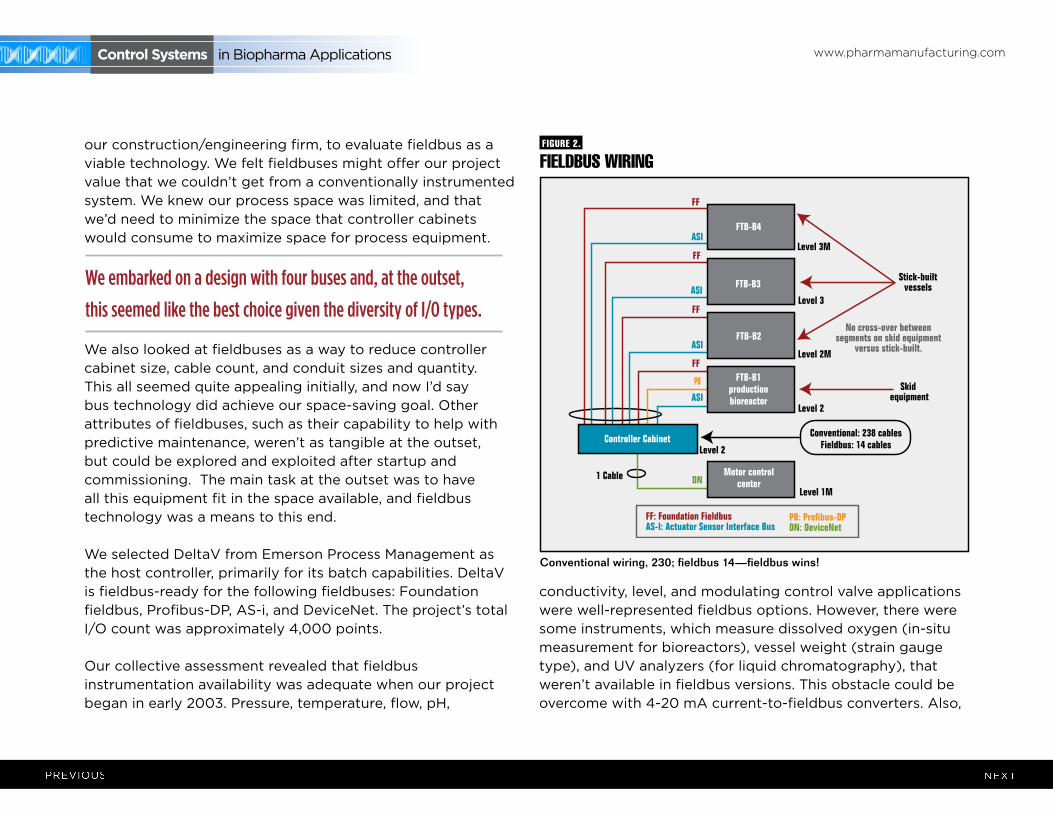
fIEldbus WIRINg
Conventional wiring, 230; fieldbus 14—fieldbus wins!
fIguRE 2.
Harvesttank
I/O: 56
I/O: 126
I/O: 56
Production bioreactor
Media feed tank
To purification
FTB-B4
FTB-B3
FTB-B2
Level 3M
Level 3
Level 2M
Level 2
Controller Cabinet
FTB-B1productionbioreactor
FF
FF
FF
FF
ASI
ASI
ASI
ASI
PB
Motor controlcenterDN1 Cable
Level 1M
Level 2
Conventional: 238 cablesFieldbus: 14 cables
Stick-builtvessels
Skid equipment
No cross-over between segments on skid equipment
versus stick-built.
FF: Foundation FieldbusAS-I: Actuator Sensor Interface Bus
PB: Profibus-DPDN: DeviceNet
www.pharmamanufacturing.com Control systems in Biopharma Applications
http://www.festo.com/net/SupportPortal/Files/291878/13_9-09%20-%20Biotech%20Control%20Solutions.pdf
mass flow controllers, which are used extensively with bioreactor equipment, weren’t found to be Foundation fieldbus ready, but were available with a Profibus-DP interface. Since it appeared that two
fieldbuses would be required to address the traditional analog-type signaling, we selected Foundation fieldbus and Profibus-DP.
Open/close valves and discrete input devices deployed in a general-purpose, electrical environment were easily addressed with the simple AS-i bit-bus. There were many opportunities for actuating rising-stem or quarter-turn valves, which are used primarily for sanitary diaphragm valves and quarter-turn ball valves. Also, AS-i was used for discrete input devices, such as valve limit switches and proximity switches found on process transfer panels. Though simple in its implementation, we recognized early that AS-i would require a close eye to make sure we didn’t exceed its segment-length criteria. Typically, this is 100 meters, and then it’s time to add a repeater and power supply before extending another 100 meters. This could be repeated one more time for a total of 300 meters per segment. We didn’t recognize the length limit as a non-starter because most of the valves are clustered in close proximity to one another, especially on skid equipment, and so we embraced this bus for most of the discrete I/O requirements.
However, AS-i bus isn’t suitable for use in electrically classified process spaces
due to its high power requirements. Open/close valving and discrete input devices in electrically classified environments were addressed with intrinsically-safe remote I/O using Profibus-DP.
Either Profibus-DP or DeviceNet could address single-speed and variable-speed motors, and there are many of these in biopharmaceutical processes. We chose DeviceNet primarily based on the merits of the host system having a rather nice graphical interface that allowed configuration of any node device at the host location. Examples of drive configuration at Genzyme include the need to configure full-load amps
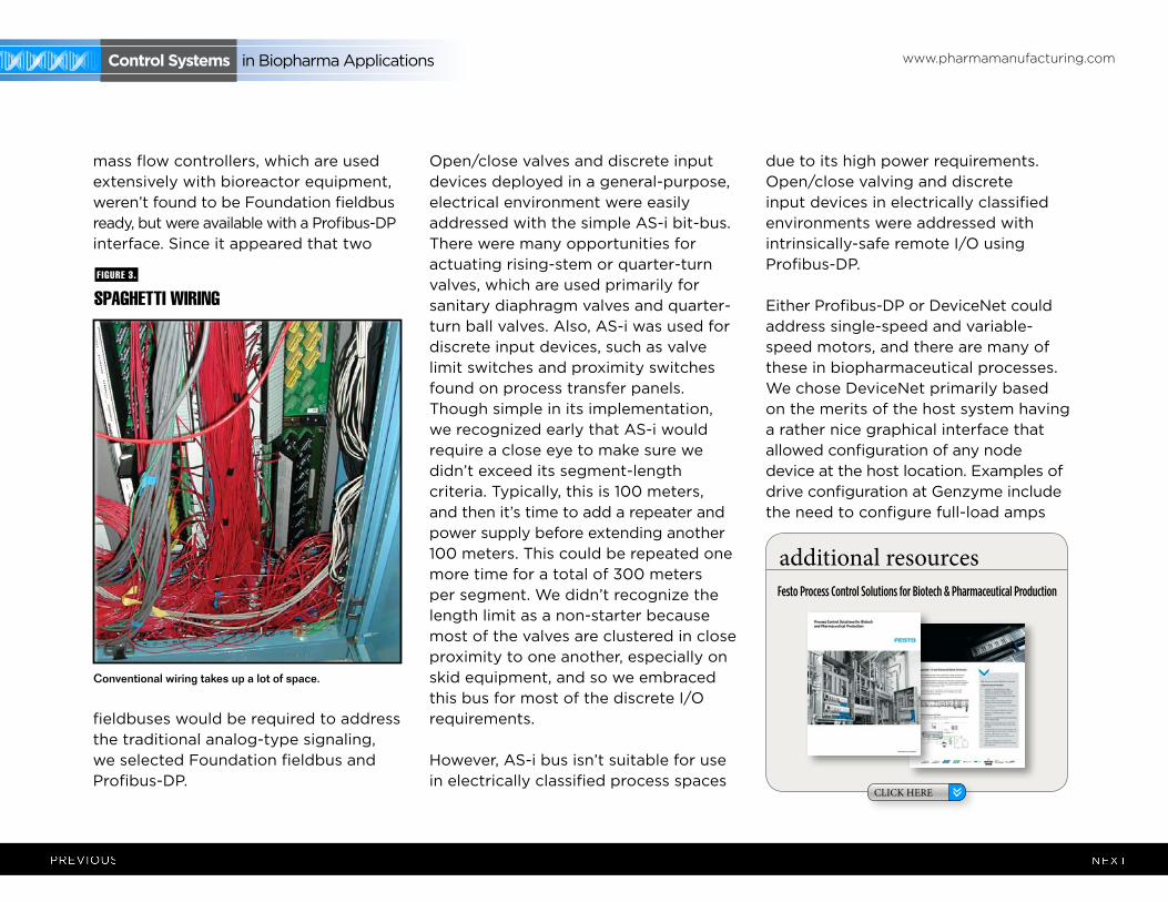
Conventional wiring takes up a lot of space.
additional resources
CLICK HERE
Festo Process Control Solutions for Biotech & Pharmaceutical Production
spAghETTI WIRINgfIguRE 3.

www.pharmamanufacturing.com Control systems in Biopharma Applications
for overload protection, acceleration and deceleration ramp rates, stop modes of coast or ramp, etc. The ability to troubleshoot drive issues was also available with the host DeviceNet interface.
Consequently, we embarked on a design with four fieldbuses. At the outset, this seemed like the best choice given the diversity of I/O types. Although I believe we have a technically solid I/O subsystem with our four fieldbuses, there’s probably a more optimal design approach if one considers the troubleshooting, maintenance, spare parts, and training aspects of each bus, which are unique. Clearly, one fieldbus doesn’t get us there, but maybe someday that will be a reality. I think, at best, given the timeframe of our project, we could have reduced the bus count to three, and, today, maybe to two. Live and learn.
Perhaps more important is the advance of technology in the past two years for increased bus devices, as well as some fundamental bus topology advances with AS-i. For example, this bus can now extend 300 meters without
repeaters, and instead uses a bus tuner that sits at the end of the segment to obviate earlier length limits.
We also know that fieldbus instrumentation is more expensive from an initial purchase standpoint. We didn’t track our construction costs in a way that would allow us to say with certainty that we realized installation savings. We believe that it should have been less costly due to smaller controller cabinets, fewer field cables, and fewer conduits. Our perception is that the overall cost was less, but we don’t really know by how much. I think our biggest savings are still yet to come with the predictive maintenance model inherent in Foundation fieldbus. Foundation fieldbus transmits device status along with the process variable, so it’s possible to receive device health information regarding imminent instrument failure. In the biopharm industry, this could mean the difference between a successful multi-day or month batch run and a failure, which could run into the millions of dollars in lost product. Therefore, this is the cost savings on which we’d rather focus our attention.
Fieldbus ArChiTeCTureThe following example shows how Genzyme’s multi-bus architecture was deployed in one of our process suites. Figure 1 shows a typical bioreactor train, which comprises a media feed tank, bioreactor, and harvest tank with their I/O requirements. If this bioreactor train had been conventionally wired, a combined total of 238 cables would have been pulled between a controller cabinet and the process equipment.
Figure 2 depicts a cable block diagram for a fieldbus implementation of this same bioreactor train. You’ll notice that there’s a dramatic reduction in the cable quantity; only 14 home-run cables are required
Criteria used for assessing the viability of fieldbuses
include the following:
1) Instrumentation availability: are instruments typically
found in a biopharm facility available with fieldbus?
2) Bus selection and bus quantity: would it require two,
three, or four fieldbuses to address the various I/O types?
3) Electrical classification: could bus instrumentation be
deployed in electrically hazardous environments?
4) Cost: is bus implementation more expensive? If so, is there
payback over time based on a predictive maintenance
model (inherent in bus systems) compared to our present
run-to-failure?
ARE fIEldbusEs RIghT fOR bIOphARmA ANd YOu?
www.pharmamanufacturing.com Control systems in Biopharma Applications
between the controller cabinet and the field terminal boxes (FTBs). These FTBs are strategically located in the process suite close to the process vessels to minimize instrument cabling that fans out from the FTB to each instrument.
FTB-B1, which wires to the bioreactor skid, includes two Foundation fieldbus segments, two AS-i segments, and one Profibus segment. The segments don’t extend beyond the bioreactor to other vessels, even if they had instruments nearby these segments. This was done by design to maintain segment segregation between skid equipment, such as bioreactors and field-assembled, fixed tanks. Bioreactors are the only process skids that use redundant instrumentation, specifically, dissolved oxygen and pH measurement. These redundant instruments share the same segment. We didn’t design for redundant segments in this case because a bioreactor is unique in that you must have all instruments and valves functional. If not, you shut down the reactor. The redundant transmitters provide assurance that we’ll likely have at least one operational by the end of a bioreactor run, even if there’s a sensor
failure or probe fouling on one of the two. Sensors can’t be changed underway because they’re within the sterile boundary of the reactor.
FTB-B2, 3, and 4 are distributed by elevation to pick up the top and bottom instruments of the media and harvest tanks for our example bioreactor train.
Foundation fieldbus and AS-i bus are both powered buses, and no additional power supplies are required in the FTBs. One DeviceNet segment exists to pick up the agitators’ variable-speed drives and single-speed pump motors.
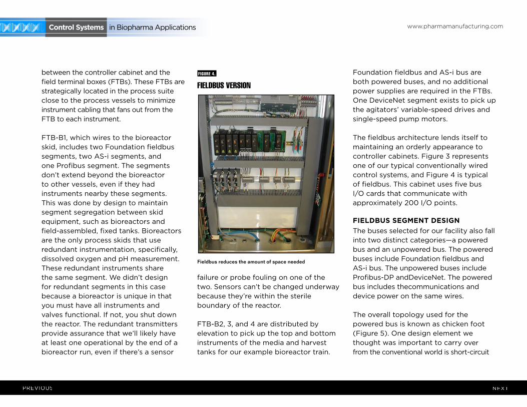
The fieldbus architecture lends itself to maintaining an orderly appearance to controller cabinets. Figure 3 represents one of our typical conventionally wired control systems, and Figure 4 is typical of fieldbus. This cabinet uses five bus I/O cards that communicate with approximately 200 I/O points.
Fieldbus seGmenT desiGnThe buses selected for our facility also fall into two distinct categories—a powered bus and an unpowered bus. The powered buses include Foundation fieldbus and AS-i bus. The unpowered buses include Profibus-DP andDeviceNet. The powered bus includes thecommunications and device power on the same wires.
The overall topology used for the powered bus is known as chicken foot (Figure 5). One design element we thought was important to carry over from the conventional world is short-circuit
fIEldbus VERsION
Fieldbus reduces the amount of space needed
fIguRE 4.
www.pharmamanufacturing.com Control systems in Biopharma Applications
ChICKENfOOT!fIguRE 5.
F
TV LT
F
FT
F
AT
F
TT
Spur 1 Spur 2 Spur 3 Spur 4 Spur 5F
fuse
FFieldbusI/O card
Controlcabinet
Trunk
Field
FieldbusI/O card
Controlcabinet Field
Fieldtermination
box
Relcom spurguardfor foundation fieldbus
PT
LT
TV
Relcom spurguardfor ASI bus
XV
ZC
ZS
FieldbusI/O card
Controlcabinet Field
Fieldtermination
box
Pressuretransmitter
Level transmitter
Temperaturecontrol valve
Open/closevalve
Proximityswitch
Rupture disksensor
spuRguARd TO ThE REsCuE
fIguRE 6.
F
TV LT
F
FT
F
AT
F
TT
Spur 1 Spur 2 Spur 3 Spur 4 Spur 5F
fuse
FFieldbusI/O card
Controlcabinet
Trunk
Field
FieldbusI/O card
Controlcabinet Field
Fieldtermination
box
Relcom spurguardfor foundation fieldbus
PT
LT
TV
Relcom spurguardfor ASI bus
XV
ZC
ZS
FieldbusI/O card
Controlcabinet Field
Fieldtermination
box
Pressuretransmitter
Level transmitter
Temperaturecontrol valve
Open/closevalve
Proximityswitch
Rupture disksensor
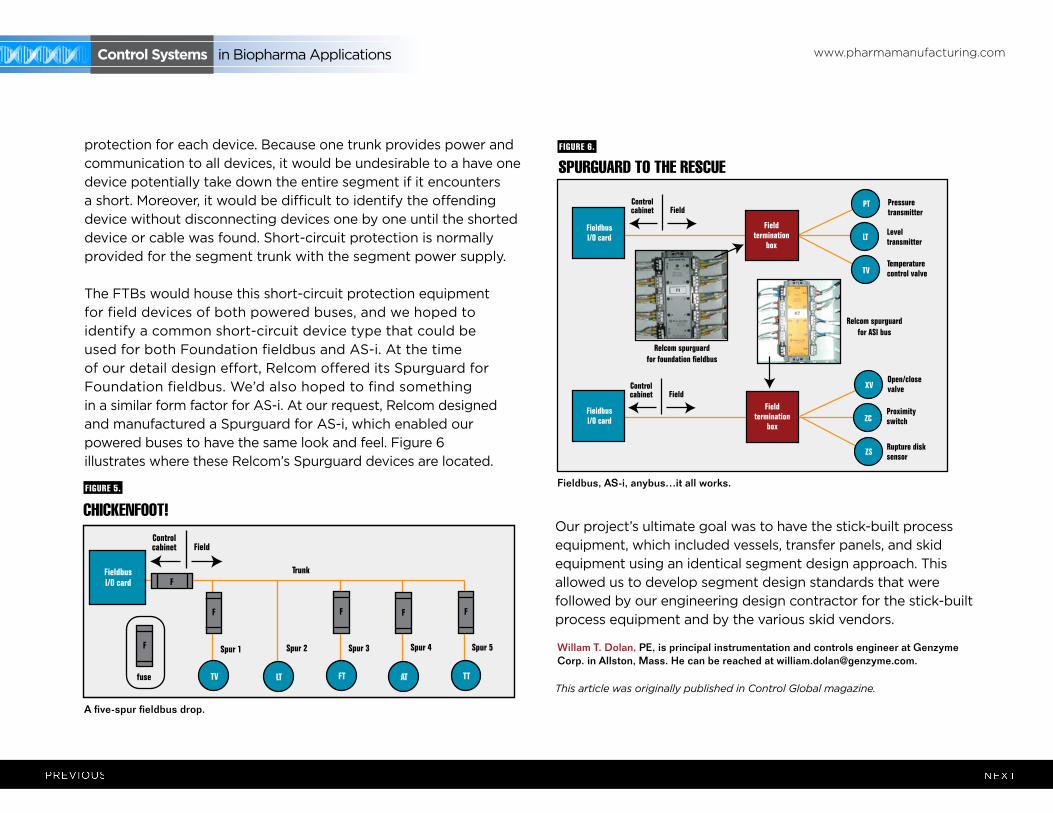
protection for each device. Because one trunk provides power and communication to all devices, it would be undesirable to a have one device potentially take down the entire segment if it encounters a short. Moreover, it would be difficult to identify the offending device without disconnecting devices one by one until the shorted device or cable was found. Short-circuit protection is normally provided for the segment trunk with the segment power supply.
The FTBs would house this short-circuit protection equipment for field devices of both powered buses, and we hoped to identify a common short-circuit device type that could be used for both Foundation fieldbus and AS-i. At the time of our detail design effort, Relcom offered its Spurguard for Foundation fieldbus. We’d also hoped to find something in a similar form factor for AS-i. At our request, Relcom designed and manufactured a Spurguard for AS-i, which enabled our powered buses to have the same look and feel. Figure 6 illustrates where these Relcom’s Spurguard devices are located.
Our project’s ultimate goal was to have the stick-built process equipment, which included vessels, transfer panels, and skid equipment using an identical segment design approach. This allowed us to develop segment design standards that were followed by our engineering design contractor for the stick-built process equipment and by the various skid vendors.
This article was originally published in Control Global magazine.
Willam T. Dolan, PE, is principal instrumentation and controls engineer at Genzyme Corp. in Allston, Mass. He can be reached at [email protected].
A five-spur fieldbus drop.
Fieldbus, AS-i, anybus…it all works.
www.pharmamanufacturing.com Control systems in Biopharma Applications
Genzyme Corp. recently installed a multi-bus control system platform at its 12-year-old pharmaceutical facility in Allston, Mass.
This was our first introduction to bus technology at Genzyme, and our subsequent selection of bus technologies was based on the process equipment needs within a cell-culture and protein-purification manufacturing environment. Bus technology is used in process areas electrically rated General Purpose and Class 1, Div. 2.
[“Fieldbus in Biopharma, Part 1,” Control, July ’06, p.58, focused on why Genzyme decided to use fieldbus, how and where it was deployed, and what architecture was used. Part 2 continues coverage of how Genzyme’s fieldbus segments were designed.]
more seGmenT desiGnThe buses selected included powered buses FF and AS-i, while the unpowered
buses are Profibus-DP and DeviceNet. The goal was to have the stick-built process equipment use an identical segment design. This allowed us to develop segment design standards that were followed by our engineering design contractor and the skid vendors.
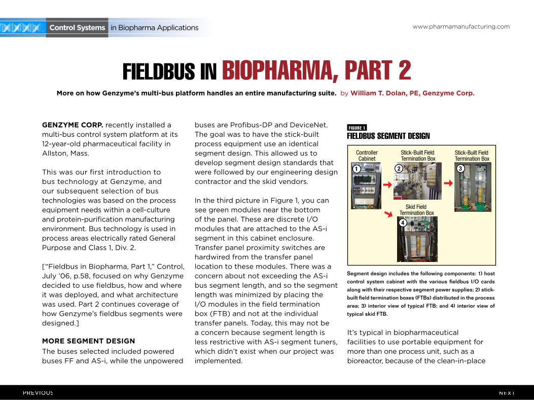
In the third picture in Figure 1, you can see green modules near the bottom of the panel. These are discrete I/O modules that are attached to the AS-i segment in this cabinet enclosure. Transfer panel proximity switches are hardwired from the transfer panel location to these modules. There was a concern about not exceeding the AS-i bus segment length, and so the segment length was minimized by placing the I/O modules in the field termination box (FTB) and not at the individual transfer panels. Today, this may not be a concern because segment length is less restrictive with AS-i segment tuners, which didn’t exist when our project was implemented.
It’s typical in biopharmaceutical facilities to use portable equipment for more than one process unit, such as a bioreactor, because of the clean-in-place
fIEldbus IN bIOphARmA, pART 2
fIEldbus sEgmENT dEsIgN
Segment design includes the following components: 1) host control system cabinet with the various fieldbus I/O cards along with their respective segment power supplies; 2) stick-built field termination boxes (FTBs) distributed in the process area; 3) interior view of typical FTB; and 4) interior view of typical skid FTB.
fIguRE 1
T H E O N L I N E R E S O U R C E O F C O N T R O L M A G A Z I N ESeptember 2006
ControllerCabinet
Stick-Built Field Termination Box
Stick-Built Field Termination Box
Skid Field Termination Box
1 2 3
4
more on how Genzyme’s multi-bus platform handles an entire manufacturing suite. by William T. dolan, pe, Genzyme Corp.
www.pharmamanufacturing.com Control systems in Biopharma Applications
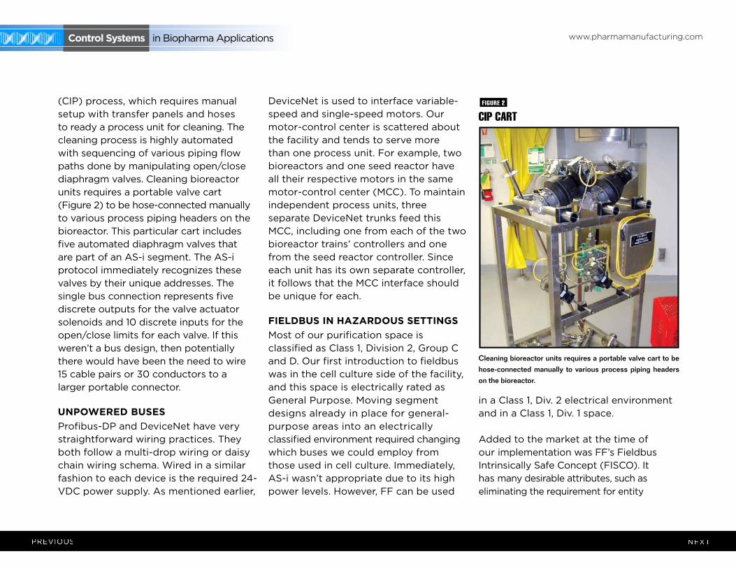
(CIP) process, which requires manual setup with transfer panels and hoses to ready a process unit for cleaning. The cleaning process is highly automated with sequencing of various piping flow paths done by manipulating open/close diaphragm valves. Cleaning bioreactor units requires a portable valve cart (Figure 2) to be hose-connected manually to various process piping headers on the bioreactor. This particular cart includes five automated diaphragm valves that are part of an AS-i segment. The AS-i protocol immediately recognizes these valves by their unique addresses. The single bus connection represents five discrete outputs for the valve actuator solenoids and 10 discrete inputs for the open/close limits for each valve. If this weren’t a bus design, then potentially there would have been the need to wire 15 cable pairs or 30 conductors to a larger portable connector.
unpoWered busesProfibus-DP and DeviceNet have very straightforward wiring practices. They both follow a multi-drop wiring or daisy chain wiring schema. Wired in a similar fashion to each device is the required 24-VDC power supply. As mentioned earlier,
DeviceNet is used to interface variable-speed and single-speed motors. Our motor-control center is scattered about the facility and tends to serve more than one process unit. For example, two bioreactors and one seed reactor have all their respective motors in the same motor-control center (MCC). To maintain independent process units, three separate DeviceNet trunks feed this MCC, including one from each of the two bioreactor trains’ controllers and one from the seed reactor controller. Since each unit has its own separate controller, it follows that the MCC interface should be unique for each.
Fieldbus in hAzArdous seTTinGsMost of our purification space is classified as Class 1, Division 2, Group C and D. Our first introduction to fieldbus was in the cell culture side of the facility, and this space is electrically rated as General Purpose. Moving segment designs already in place for general-purpose areas into an electrically classified environment required changing which buses we could employ from those used in cell culture. Immediately, AS-i wasn’t appropriate due to its high power levels. However, FF can be used
in a Class 1, Div. 2 electrical environment and in a Class 1, Div. 1 space.
Added to the market at the time of our implementation was FF’s Fieldbus Intrinsically Safe Concept (FISCO). It has many desirable attributes, such as eliminating the requirement for entity
CIp CART
Cleaning bioreactor units requires a portable valve cart to be hose-connected manually to various process piping headers on the bioreactor.
fIguRE 2
www.pharmamanufacturing.com Control systems in Biopharma Applications
parameter calculations, less documentation to develop and maintain, instruments that can be added later to the segment without the need for further segment analysis, and higher power levels that allow more devices per segment. Before FISCO, segment device count usually couldn’t exceed four devices for an Entity IS segment, but the count could be as high as 12 with FISCO.
Because it was new, our design presented a concern regarding the availability of field devices certified for a FISCO implementation. We found all the devices we used on the cell culture side of the facility that would be used in purification were FISCO-certified, and so we could continue to use the same suppliers and devices. Though the FISCO implementation is designed for a Class 1, Div. 1 electrical environment and our space classification is Class 1, Div. 2, we decided to pursue the FISCO design because it meant that all segment and device maintenance and troubleshooting could be accomplished with a powered segment or device.
Shortly after FISCO was introduced, another non-incendive design appeared. This Fieldbus Non-Incendive Concept (FNICO) is intended specifically for Class 1, Div. 2 electrical environments. There was a comfort level in the facility with intrinsically safe (IS)
implementation, which ensures that facilities personnel never have to think about powering down instrumentation prior to performing maintenance or troubleshooting.
Figure 3 depicts a Foundation Fieldbus segment design that has the same look and feel as Foundation Fieldbus used in general purpose areas.
Earlier, we mentioned that AS-i wasn’t appropriate for IS applications. Therefore, another solution was sought for the discrete devices in the electrically classified space. An IS implementation with FISCO and an IS solution were envisioned for the discrete devices. We tried to keep host controller cabinets in safe-area spaces, and only allow I/O subsystems in process spaces. IS remote I/O was installed in the process space to interface to low-power solenoid operators for valve actuators, valve position limit switches, rupture disk indicators and transfer panel proximity switches. The remote I/O modules are intrinsically safe, but the communications, Profibus-DP, to each is not. Profibus-DP can’t be implemented intrinsically safe though it’s a non-incendive design.
Fieldbus insTrumenTATion ATTribuTesOur experience with fieldbus shows there are some fieldbus devices that lend themselves nicely to biopharma applications. A few instruments can illustrate this point.
The first is the Rosemount 848T temperature transmitter, which also allows for other input types besides RTD and thermocouple. Steam-in-place (SIP) is a common process in biopharmaceutical facilities for sterilizing process vessels and piping. SIP is usually automated with multiple temperature elements at various low-point condensate drains, and usually has five to eight temperature elements http://www.festo.com/net/SupportPortal/Files/26965/Control_Cabinet_Broch_en.pdf
additional resources
CLICK HERE
Festo Control Cabinet Solutions for the Process Industry
www.pharmamanufacturing.com Control systems in Biopharma Applications
per vessel. In the case of a bioreactor, the temperature element count can approach 30 or more. In the early design stages of our cell culture facility, there was some concern about how to handle the many RTD inputs with a bus system. Certainly, a Foundation fieldbus transmitter for each input would be unwieldy from a construction standpoint, not to mention the cost. Fortunately, 848T allows up to eight inputs per instrument, which reduces the device count. We also use this device to convert conventional 4-20 mA/DC devices to Foundation fieldbus.
Likewise, Micromotion mass flowmeters are used extensively in our facility, for example, on chromatography skids. From one fieldbus connection to the device, we can realize all four process variables measured or calculated by the mass flowmeter. These include mass flow, volumetric flow, fluid temperature and fluid density. Typically, volumetric flow is the primary value of interest and is a calculated value from the device (mass flow/density). Volumetric flow is used as the process variable for the flow control loop on the chromatography skid. Initial running of the skid requires priming the inlet buffer lines.
While executing the prime phase, we’ve noticed that when two-phase flow is introduced through the meter, the density will drop in proportion to the two-phase mixture, causing the volumetric flow to read high. Since we prime the various buffer lines based on passing a certain liquid volume, it’s important to totalize only liquid flow and not two-phase flow. To prevent totalizing of two-phase flow, we use the density input, detect when it’s no longer that of a liquid and then turn off the totalizer. In this case, the host controller is actually writing to a parameter in memory in the fieldbus device. This ensures that all buffer lines have had the predetermined liquid volume transferred and shows the two-way communication available with fieldbus devices.In addition, Gemu manufactures valve actuators for on/off diaphragm
valves. These valve actuators communicate to the host by way of AS-i bus. The valve actuators have a solenoid valve and open/close limit switches in the actuator’s topworks. It’s not unusual to find diaphragm valves open for SIP and then indicate “valve not closed” when commanded “close” at the end of SIP. This is due to the diaphragm being more malleable when heated, which allows the actuator stem to drive the diaphragm slightly deeper into the weir of the valve body past the previously set or cold diaphragm-closed position. This device includes a programmable hysteresis for the open and closed limit switch that allows for process condition. Typically, it’s the closed limit switch we’re interested in confirming in the case of sterile boundary valves.
Willam T. Dolan, PE, is principal instrumentation and controls engineer at Genzyme Corp. in Allston, Mass. He can be reached at [email protected].
This article was originally published in Control Global magazine.
Fieldbus helped us in five areas:• Expandedviewforoperators,engineersandtechnicians.Fromanyoperatorworkstation,
it’s possible to drill down to the instrument configuration and quickly assess current instrument operating status.
• Reducedwiringandinstallationcosts.Ourqualitativesensetellsusthat,becauseof the reduced number of home-run cables and associated conduit size reductions and quantities, our installation cost must be less.
• ReducedI/Oequipmentandcontrolcabinetsize.Thoughourcontrollercabinetsizes are reduced, we may have more cabinets compared to a conventionally wired system because of the added cabinet count for field termination boxes.
• Reductioninman-hoursforcommissioningandstart-up.Webelievetheeffortisessentiallyidentical for fieldbus and conventionally instrumented system. Perhaps we haven’t optimized this activity because there are many proponents that advocate this point.
• Reducedtotalcostofownership.Webelievethiswillbetruewhenweeliminate“runto failure” or scheduled maintenance. Cell culture production can run for months at a time, so it’s imperative that the instrumentation platform be robust so bioreactor runs aren’t termi-nated early due to instrument problems. We have evidence to date that the fieldbus platform has enabled us to remedy imminent device failure before the start of a production run.
ImpACT Of fIEldbus AT gENzYmE
www.pharmamanufacturing.com Control systems in Biopharma Applications
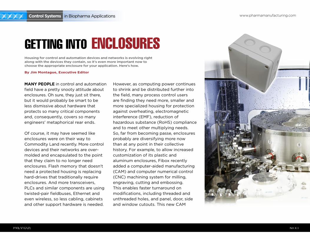
mAny people in control and automation field have a pretty snooty attitude about enclosures. Oh sure, they just sit there, but it would probably be smart to be less dismissive about hardware that protects so many critical components and, consequently, covers so many engineers' metaphorical rear ends.
Of course, it may have seemed like enclosures were on their way to Commodity Land recently. More control devices and their networks are over-molded and encapsulated to the point that they claim to no longer need enclosures. Flash memory that doesn't need a protected housing is replacing hard-drives that traditionally require enclosures. And more transceivers, PLCs and similar components are using twisted-pair fieldbuses, Ethernet and even wireless, so less cabling, cabinets and other support hardware is needed.
However, as computing power continues to shrink and be distributed further into the field, many process control users are finding they need more, smaller and more specialized housing for protection against overheating, electromagnetic interference (EMF), reduction of hazardous substance (RoHS) compliance and to meet other multiplying needs. So, far from becoming passe, enclosures probably are diversifying more now than at any point in their collective history. For example, to allow increased customization of its plastic and aluminum enclosures, Fibox recently added a computer-aided manufacturing (CAM) and computer numerical control (CNC) machining system for milling, engraving, cutting and embossing. This enables faster turnaround on modifications, including threaded and unthreaded holes, and panel, door, side and window cutouts. This new CAM
gETTINg INTO ENClOsuREshousing for control and automation devices and networks is evolving right along with the devices they contain, so it's even more important now to choose the appropriate enclosure for your application. here's how.
by Jim montague, executive editor
www.pharmamanufacturing.com Control systems in Biopharma Applications
machining system can customize any of Fibox's more than 750 standard enclosures. Also, a graphics converter built into the new CAM system's software makes it easy to accept files from computer-aided design (CAD) programs and convert them to the proper machining instructions.
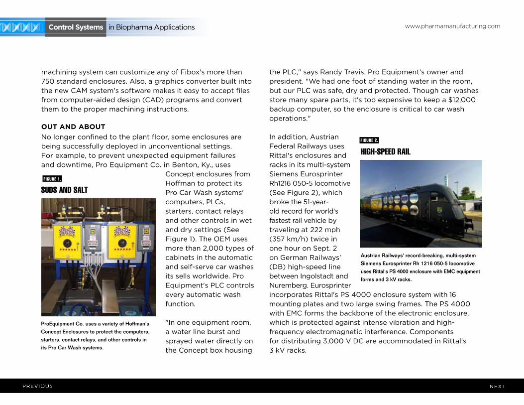
ouT And AbouTNo longer confined to the plant floor, some enclosures are being successfully deployed in unconventional settings. For example, to prevent unexpected equipment failures and downtime, Pro Equipment Co. in Benton, Ky., uses
Concept enclosures from Hoffman to protect its Pro Car Wash systems' computers, PLCs, starters, contact relays and other controls in wet and dry settings (See Figure 1). The OEM uses more than 2,000 types of cabinets in the automatic and self-serve car washes its sells worldwide. Pro Equipment's PLC controls every automatic wash function.
"In one equipment room, a water line burst and sprayed water directly on the Concept box housing
the PLC," says Randy Travis, Pro Equipment's owner and president. "We had one foot of standing water in the room, but our PLC was safe, dry and protected. Though car washes store many spare parts, it's too expensive to keep a $12,000 backup computer, so the enclosure is critical to car wash operations."
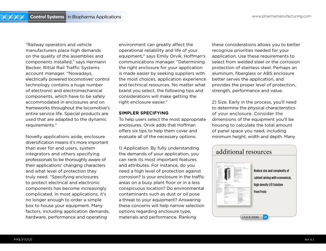
In addition, Austrian Federal Railways uses Rittal's enclosures and racks in its multi-system Siemens Eurosprinter Rh1216 050-5 locomotive (See Figure 2), which broke the 51-year-old record for world's fastest rail vehicle by traveling at 222 mph (357 km/h) twice in one hour on Sept. 2 on German Railways' (DB) high-speed line between Ingolstadt and Nuremberg. Eurosprinter incorporates Rittal's PS 4000 enclosure system with 16 mounting plates and two large swing frames. The PS 4000 with EMC forms the backbone of the electronic enclosure, which is protected against intense vibration and high-frequency electromagnetic interference. Components for distributing 3,000 V DC are accommodated in Rittal's 3 kV racks.
hIgh-spEEd RAIl
AustrianRailways'record-breaking,multi-system
SiemensEurosprinterRh1216050-5locomotive
usesRittal'sPS4000enclosurewithEMCequipment
forms and 3 kV racks.
fIguRE 2.
suds ANd sAlT
ProEquipmentCo.usesavarietyofHoffman'sConcept Enclosures to protect the computers, starters, contact relays, and other controls in its Pro Car Wash systems.
fIguRE 1.
www.pharmamanufacturing.com Control systems in Biopharma Applications
"Railway operators and vehicle manufacturers place high demands on the quality of the assemblies and components installed," says Hermann Becker, Rittal Rail Traffic Systems account manager. "Nowadays, electrically powered locomotives' control technology contains a huge number of electronic and electromechanical components, which have to be safely accommodated in enclosures and on frameworks throughout the locomotive's entire service life. Special products are used that are adapted to the dynamic requirements."
Novelty applications aside, enclosure diversification means it's more important than ever for end users, system integrators and others specifying professionals to be thoroughly aware of their applications' changing characters and what level of protection they truly need. "Specifying enclosures to protect electrical and electronic components has become increasingly complicated. In most applications, it's no longer enough to order a simple box to house your equipment. Many factors, including application demands, hardware, performance and operating
environment can greatly affect the operational reliability and life of your equipment," says Emily Orvik, Hoffman's communications manager. "Determining the right enclosure for your application is made easier by seeking suppliers with the most choices, application experience and technical resources. No matter what brand you select, the following tips and considerations will make getting the right enclosure easier."
simpler speCiFyinG To help users select the most appropriate enclosures, Orvik adds that Hoffman offers six tips to help them cover and evaluate all of the necessary options:
1) Application. By fully understanding the demands of your application, you can rank its most important features and attributes. For instance, do you need a high level of protection against corrosion? Is your enclosure in the traffic areas on a busy plant floor or in a less conspicuous location? Do environmental contaminants such as dust or oil pose a threat to your equipment? Answering these concerns will help narrow selection options regarding enclosure type, materials and performance. Ranking
these considerations allows you to better recognize priorities needed for your application. Use these requirements to select from welded steel or the corrosion protection of stainless steel. Perhaps an aluminum, fiberglass or ABS enclosure better serves the application, and provides the proper level of protection, strength, performance and value.
2) Size. Early in the process, you'll need to determine the physical characteristics of your enclosure. Consider the dimensions of the equipment you'll be housing to calculate the total amount of panel space you need, including minimum height, width and depth. Many
http://www.festo.com/cms/en-us_us/16373.htm
additional resources
CLICK HERE
Reduce size and complexity of
cabinet wiring with economical,
high density I/O Solution
from Festo
www.pharmamanufacturing.com Control systems in Biopharma Applications
control and network devices require 19-inch and 23-inch rack standards, which may enable you to select a modular enclosure design, while other types of electronics may require a different size to accommodate your equipment.
After you determine the containment size of the enclosure, you'll also need to consider if any space or use limitations exist in the installation environment. There are often many different cabinet and mounting configurations that can provide the performance you require. An experienced application engineer or knowledgeable distributor can present options that will fit most effectively within your workspace. These might include horizontal, low-profile, or wall-mount cabinets or even portable enclosures.
3) User Interface. It's seldom adequate to specify a simple square box. Examine your need to access the enclosed equipment. Will accessories make the enclosure user-friendly? What is the anticipated frequency of service or maintenance? Are there cleaning, ergonomic, security, safety and usage considerations? Considering these requirements, you might select removable panels, wiring and/or backplane access. This can be through an added set of doors, locking latches, reconfigurable interior mounting, secure cabinets with partial accessibility to keyboards or a limited number of components. You also can address usage issues with operator interface workstations or pushbutton enclosures. You'll also need to assess the routing of wiring, and consider the mounting option that will work best for your application.
With every enclosure there are two environments that require attention: the interior environment of the populated enclosure and the exterior environment surrounding the enclosure. Each presents distinct challenges to proper specification. NEMA standards can help you evaluate your needs where non-hazardous environmental conditions exist, and other worldwide standards can help you narrow your specifications as well.
4) Environment. Examine the immediate area in which you intend to install the enclosure. Will your enclosure be installed indoors or outside? Assess the environmental threats to your components. Contaminants may range from dust, water, oil and dirt, harsh chemicals, UV light, solar heat gain, weather forces, salt water or temperature extremes. In an equipment-rich environment, hidden threats might include electromagnetic or radio-frequency interference, which can play havoc with enclosed equipment. In a busy industrial area, the enclosure could be subject to periodic accidental impact or shock. And
www.pharmamanufacturing.com Control systems in Biopharma Applications
more sensitive, critical components could be at risk from excessive vibration or seismic dangers in certain geographic regions. Suppliers offering a complete line of enclosures and in-house testing can address your performance needs in even the most demanding environments.
5) Additional Protection. Whether generated internally or externally, excessive heat and humidity are the most common challenges in protecting components from premature failure or unreliable performance. Today's compact devices consume more power and generate more heat in less space, making thermal management an even more crucial consideration when specifying an enclosure. Because managing excessive internal temperatures is so critical to reliable operation, most manufacturers offer solutions to deal with these conditions. For example, Hoffman provides free thermal management sizing and selection software to help you calculate your heat dissipation needs based on your specific equipment, and suggests the appropriate thermal solution for your enclosure.
6) Certifications. Ratings governed by national and international standards organizations such as NEMA, UL, CSA, IEC and VDE are critical to help you specify the appropriate product for your application. These ratings standardize product performance from one manufacturer to the next, identify an enclosure's ability to withstand environmental influences, and/or offer assurance that products conform to established guidelines for performance and public safety. Standards such as UL and CSA require enclosure testing by qualified evaluators and perform
site inspections to assure manufacturing compliance for methods and materials. By selecting a manufacturer that demonstrates strict adherence and fluency with international standards, your enclosure will not only perform in a safe and effective manner within your application, but will also satisfy electrical/building codes, OSHA requirements and even workers' union-based provisions.
In addition, RoHS, which regulates environmentally sound end-of-life disposal of components, continues to receive attention. This EU directive went into affect in July 2006. China and California are expected to follow with their own versions.
insTAllATion ConsiderATions
In addition, Stahlin Enclosures reports that several installation factors should be considered when selecting an enclosure:
www.pharmamanufacturing.com Control systems in Biopharma Applications
1) Equipment mounting panel. The back panels are optional and must be selected and ordered separately. Enclosure back panels can be fabricated from aluminum, painted carbon steel, fiberglass and stainless steel. The enclosure construction material and the amount of time that an enclosure may be open and exposed to the application environment should be considered in making this selection.
2) Wiring connections. Hubs for connecting conduit to enclosures include: PVC-coated metal hubs designed for use with PVC-coated rigid metal conduit systems, PVC hubs for use with PVC conduit, and aluminum hubs for use with metal conduit. All hubs use an o-ring to seal between the hub and enclosure wall. Nylon cord-grip fittings are designed to seal out moisture, dust or other foreign material, and to form a positive sealing grip when installing an entrance cord or wire through an enclosure wall. Likewise, Sigma-form, feed-through seals provide a watertight, fume-tight seal at cable entrances to enclosures.
3) Enclosure mounting. Besides typical wall-mount and floor-mount configurations, some enclosures also are available with pedestal mounting, mounting feet and/or custom-fabricated floor mounting kits.
4) Grounding. Grounding electrical and electronic equipment in enclosures is extremely important for two reasons: to ensure safety of personnel operating the equipment and to prevent equipment damage from transient voltages generated by switching conditions, system faults and EMI/RFI. Grounding continuity must be maintained between the equipment in the enclosure and the conduits or cables entering and exiting the enclosure. Because fiberglass is an insulator, grounding must be maintained by
using jumpers between internal equipment and conduit or cable connections in fiberglass enclosures. To meet this need, conduit hubs for use in fiberglass enclosures must have built-in grounding screws to comply with UL and NEC requirements.
The key to a reliable electrical system including the enclosure is a grounded system with all materials properly selected for the application and installed in accord with the recommended installation guidelines, the product listing and NEC. For more information on grounding, refer to UL's Specification UL 50 and NEC Code's Article 250. seleCTion insTruCTionsTo help users learn to pick the most appropriate housings, Stahlin Enclosures has compiled a 32-page guide, which is available by clicking on the "Technical Tools" section of its website. The guide covers sizes, ratings, materials, fastenings, and other features, and even has a worksheet that users can fill out to help calculate their specifications. One of its many useful tables is presented here: IP, NEMA Protection Categories
To protect valuable electrical and electronic components, enclosures must withstand a wide range of environmental influences, whether they're located indoors or outdoors. Rittal presents many definitions and combinations of IP and NEMA rating on its www.rittal.com. website. Visitors can click on "Technical Information" under "Services & Support," and then click on "Protection Categories," or go to http://www.rittal.com/services_support/technical_information/protection_categories/index.html.
This article was originally published in Control Global magazine.

www.pharmamanufacturing.com Control systems in Biopharma Applications
http
s://w
ww.fa
cebo
ok.co
m/F
esto
USA
http
s://tw
itter.
com
/Fes
to_U
S
http
://ww
w.fes
to.co
m/y
outu
be/
http
://ww
w.lin
kedin
.com
/com
pany
/festo
-usa
Festo is the global leader providing process control solutions to the Biotech and Pharmaceutical manu-facturing industries.
With over 40 years of innovation in the United States and over 80 years globally, Festo is the manufacturer of choice for control valves, I/O and fieldbus control. Our broad range of products and services span the full needs of the automa-tion industry including cabinet design and energy reduction solutions. Festo also offers a range of process valves, actuators, sensors, air preparation, and packaging components.
Our dedication to the advancement of automation extends beyond technology to the education of current and future automation and process design-ers with simulation tools, teaching programs and on-site services.
With experts supporting industry projects in over 180 countries, Festo is the first choice for process control and control cabinets in your industry.
http://www.festo.com/net/SupportPortal/Files/291878/13_9-09%20-%20Biotech%20Control%20Solutions.pdf
http://www.festo.com/PDF_Flip/us/process-automation/index.html
http://www.festo.com/rep/en-us_us/assets/pdf/PM1111_Festo_Training.pdf
http://www.festo.com/rep/en-us_us/assets/pdf/PM1107_Festo_ComprssdAir_3.pdf
additional resourcesfor more information click on the links below
CLICK HERE
CLICK HERE
CLICK HERE
CLICK HERE
Process Control Solutions for Biotech & Pharmaceutical Production
Process Automation Product Overview
Transformation through Training – Training as your Competitive AdvantageLearn the importance of automation technical training and how it can provide biopharma manufacturers with clear competitive advantages. Bill Sicari, Manager of Festo Didactic, details the value of providing effective training to your staff to help increase efficiency.
Energy Conservation in Biotech/Pharmaceutical Production – Best Practices in Compressed Air Pharmaceutical ManufacturingSee how to improve compressed air practices in the life science industry with improvements to pneumatic technology and monitoring processes.
For more information, please contact:
Festo Corporation
Tel: 1-800-99-FESTOFax: 1-800-96-FESTOEmail: [email protected]: www.festo.com/us/biotech
Connect with us