City centre in-feed feasible by HVDC Light · PDF file · 2015-04-14City centre...
12
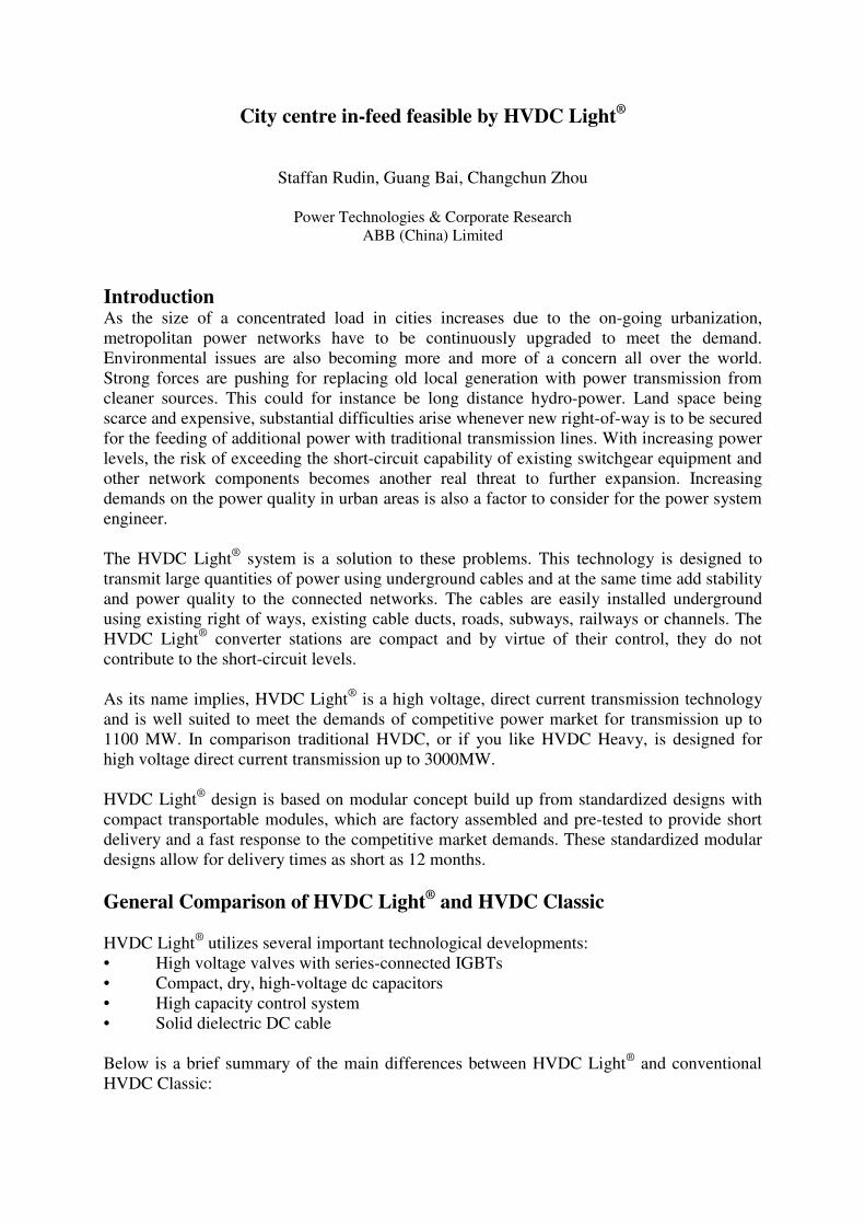
City centre in-feed feasible by HVDC Light ® Staffan Rudin, Guang Bai, Changchun Zhou Power Technologies & Corporate Research ABB (China) Limited Introduction As the size of a concentrated load in cities increases due to the on-going urbanization, metropolitan power networks have to be continuously upgraded to meet the demand. Environmental issues are also becoming more and more of a concern all over the world. Strong forces are pushing for replacing old local generation with power transmission from cleaner sources. This could for instance be long distance hydro-power. Land space being scarce and expensive, substantial difficulties arise whenever new right-of-way is to be secured for the feeding of additional power with traditional transmission lines. With increasing power levels, the risk of exceeding the short-circuit capability of existing switchgear equipment and other network components becomes another real threat to further expansion. Increasing demands on the power quality in urban areas is also a factor to consider for the power system engineer. The HVDC Light ® system is a solution to these problems. This technology is designed to transmit large quantities of power using underground cables and at the same time add stability and power quality to the connected networks. The cables are easily installed underground using existing right of ways, existing cable ducts, roads, subways, railways or channels. The HVDC Light ® converter stations are compact and by virtue of their control, they do not contribute to the short-circuit levels. As its name implies, HVDC Light ® is a high voltage, direct current transmission technology and is well suited to meet the demands of competitive power market for transmission up to 1100 MW. In comparison traditional HVDC, or if you like HVDC Heavy, is designed for high voltage direct current transmission up to 3000MW. HVDC Light ® design is based on modular concept build up from standardized designs with compact transportable modules, which are factory assembled and pre-tested to provide short delivery and a fast response to the competitive market demands. These standardized modular designs allow for delivery times as short as 12 months. General Comparison of HVDC Light ® and HVDC Classic HVDC Light ® utilizes several important technological developments: • High voltage valves with series-connected IGBTs • Compact, dry, high-voltage dc capacitors • High capacity control system • Solid dielectric DC cable Below is a brief summary of the main differences between HVDC Light ® and conventional HVDC Classic:
Transcript of City centre in-feed feasible by HVDC Light · PDF file · 2015-04-14City centre...
City centre in-feed feasible by HVDC Light®
Staffan Rudin, Guang Bai, Changchun Zhou
Power Technologies & Corporate ResearchABB (China) Limited
IntroductionAs the size of a concentrated load in cities increases due to the on-going urbanization,metropolitan power networks have to be continuously upgraded to meet the demand.Environmental issues are also becoming more and more of a concern all over the world.Strong forces are pushing for replacing old local generation with power transmission fromcleaner sources. This could for instance be long distance hydro-power. Land space beingscarce and expensive, substantial difficulties arise whenever new right-of-way is to be securedfor the feeding of additional power with traditional transmission lines. With increasing powerlevels, the risk of exceeding the short-circuit capability of existing switchgear equipment andother network components becomes another real threat to further expansion. Increasingdemands on the power quality in urban areas is also a factor to consider for the power systemengineer.
The HVDC Light® system is a solution to these problems. This technology is designed totransmit large quantities of power using underground cables and at the same time add stabilityand power quality to the connected networks. The cables are easily installed undergroundusing existing right of ways, existing cable ducts, roads, subways, railways or channels. TheHVDC Light® converter stations are compact and by virtue of their control, they do notcontribute to the short-circuit levels.
As its name implies, HVDC Light® is a high voltage, direct current transmission technologyand is well suited to meet the demands of competitive power market for transmission up to1100 MW. In comparison traditional HVDC, or if you like HVDC Heavy, is designed forhigh voltage direct current transmission up to 3000MW.
HVDC Light® design is based on modular concept build up from standardized designs withcompact transportable modules, which are factory assembled and pre-tested to provide shortdelivery and a fast response to the competitive market demands. These standardized modulardesigns allow for delivery times as short as 12 months.
General Comparison of HVDC Light® and HVDC Classic
HVDC Light® utilizes several important technological developments:• High voltage valves with series-connected IGBTs• Compact, dry, high-voltage dc capacitors• High capacity control system• Solid dielectric DC cable
Below is a brief summary of the main differences between HVDC Light® and conventionalHVDC Classic:
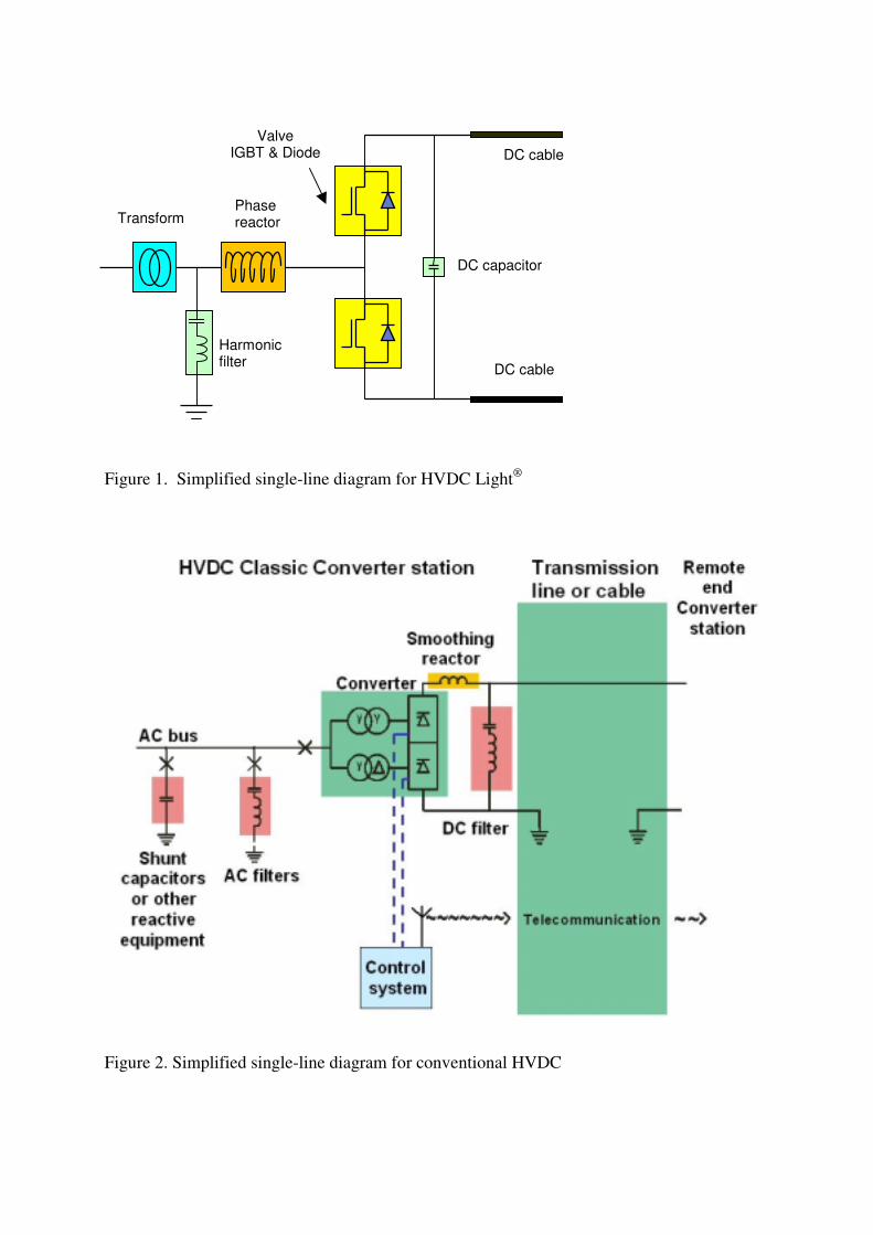
Figure 1. Simplified single-line diagram for HVDC Light®
Figure 2. Simplified single-line diagram for conventional HVDC
Phasereactor
Harmonicfilter
ValveIGBT & Diode
DC capacitor
Transform
DC cable
DC cable
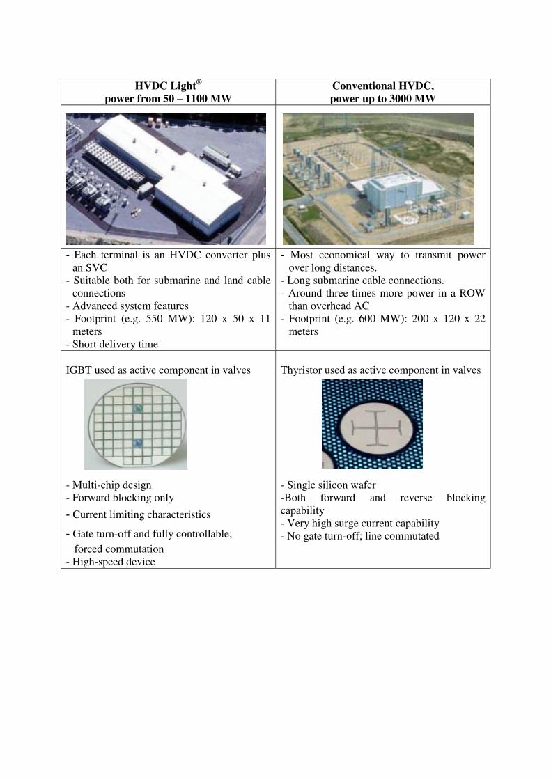
HVDC Light®
power from 50 – 1100 MWConventional HVDC,power up to 3000 MW
- Each terminal is an HVDC converter plusan SVC
- Suitable both for submarine and land cableconnections
- Advanced system features- Footprint (e.g. 550 MW): 120 x 50 x 11
meters- Short delivery time
- Most economical way to transmit powerover long distances.
- Long submarine cable connections.- Around three times more power in a ROW
than overhead AC- Footprint (e.g. 600 MW): 200 x 120 x 22
meters
IGBT used as active component in valves
- Multi-chip design- Forward blocking only
Current limiting characteristics
Gate turn-off and fully controllable;forced commutation
- High-speed device
Thyristor used as active component in valves
- Single silicon wafer-Both forward and reverse blockingcapability- Very high surge current capability- No gate turn-off; line commutated
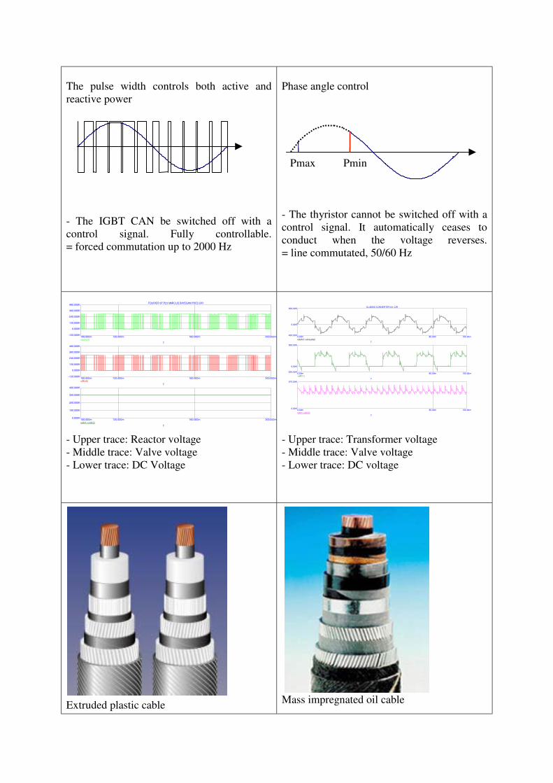
The pulse width controls both active andreactive power
- The IGBT CAN be switched off with acontrol signal. Fully controllable.= forced commutation up to 2000 Hz
Phase angle control
Pmax Pmin
- The thyristor cannot be switched off with acontrol signal. It automatically ceases toconduct when the voltage reverses.= line commutated, 50/60 Hz
- Upper trace: Reactor voltage- Middle trace: Valve voltage- Lower trace: DC Voltage
- Upper trace: Transformer voltage- Middle trace: Valve voltage- Lower trace: DC voltage
Extruded plastic cable Mass impregnated oil cable
0.00m 80.00m 100.00m-400.00K
0.00K
600.00K
v(trafo1)-v(neutral)T
0.00m 80.00m 100.00m-200.00K
0.00K
800.00K
-v(R11)T
0.00m 80.00m 100.00m0.00K
675.00K
v(dc1)-v(dc2)T
CLASSIC CONVERTER 03 .CIR
100.000m 120.000m 160.000m 200.000m-120.000K
0.000K
120.000K
240.000K
360.000K
480.000K
v(conv1)T
100.000m 120.000m 160.000m 200.000m-120.000K
0.000K
120.000K
240.000K
360.000K
480.000K
v(R39)T
100.000m 120.000m 160.000m 200.000m0.000K
100.000K
200.000K
300.000K
400.000K
v(dc1)-v(dc2)T
FOURIER 97 P23 MARCUS BAYEGAN PRES.CIR
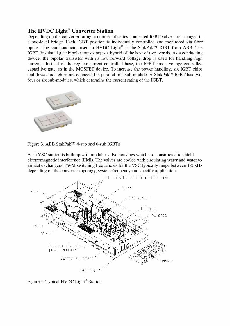
The HVDC Light® Converter StationDepending on the converter rating, a number of series-connected IGBT valves are arranged ina two-level bridge. Each IGBT position is individually controlled and monitored via fiberoptics. The semiconductor used in HVDC Light® is the StakPak IGBT from ABB. TheIGBT (insulated gate bipolar transistor) is a hybrid of the best of two worlds. As a conductingdevice, the bipolar transistor with its low forward voltage drop is used for handling highcurrents. Instead of the regular current-controlled base, the IGBT has a voltage-controlledcapacitive gate, as in the MOSFET device. To increase the power handling, six IGBT chipsand three diode chips are connected in parallel in a sub-module. A StakPak IGBT has two,four or six sub-modules, which determine the current rating of the IGBT.
Figure 3. ABB StakPak 4-sub and 6-sub IGBTs
Each VSC station is built up with modular valve housings which are constructed to shieldelectromagnetic interference (EMI). The valves are cooled with circulating water and water toairheat exchangers. PWM switching frequencies for the VSC typically range between 1-2 kHzdepending on the converter topology, system frequency and specific application.
Figure 4. Typical HVDC Light® Station
Each VSC is effectively mid-point grounded and coupled to the AC bus via phase reactorsand a power transformer with intermediary shunt AC filters. The AC filters are tuned tomultiples of the switching frequency. This arrangement minimizes harmonic content andavoids dc voltage stressesin the transformer which allows use of a standard ACpowertransformer for matching the AC network voltage to theconverter AC voltage necessaryto produce the desired DCtransmission voltage.
The HVDC Light® Cable
The HVDC Light® cable is a new design triple extruded, polymeric insulated DC-cable,whichhas been successfully type tested to150kV DC, following a comprehensive R &D program. Itis a new lightweight cable similar in appearance and characteristics toa standard AC, XLPEcable except that the problem associated with space chargeswhich breakdown the insulationwhen using AC, XLPE cables on DC has beenovercome with this new design.
The cables are operated in bipolar mode, one cable with positive polarity and one cable withnegative polarity. The cables have polymeric insulating material, which is very strong androbust. This strength and flexibility make the HVDC Light® cables perfect for severeinstallation conditions:- The land cables can be installed less costly with plowing technique.- The submarine cables can be laid in deeper waters and on rough seabeds.- HVDC cables can also be installed as overhead cables.
DC underground cables provide significant advantages, compared with overhead power lines.These include:- Reduced environmental impact, an underground cable has no visual impact.- Faster and easier issue of permits using DC underground cables.- Virtually no magnetic radiation associated with the bi-polar DC cable.
Compared with AC underground cables the HVDC Light® cable also has some significantadvantages to be considered:- DC cables require only two cables between each converter station.- DC-cables have no technical limit to distance.- DC cables can carry up to 50% more power than the equivalent AC cable.
When considering the cost of installing an HVDC Light® underground transmission it isimportant to consider the total life cost benefits and not just the initial up front capital costs.
Power System Advantage
In an HVDC Light® system the active and reactive power can be controlled at the same timelike in a synchronous converter, but the control is much faster, in the millisecond range. Thisfast control makes it possible to create any phase angle or amplitude, which can be donealmost instantaneously providing independent control of both active and reactive power. Froma system point of view it acts as a motor or a generator without mass.
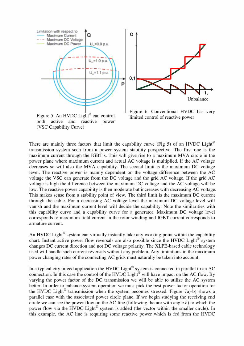
Figure 5. An HVDC Light® can controlboth active and reactive power(VSC Capability Curve)
Figure 6. Conventional HVDC has verylimited control of reactive power
There are mainly three factors that limit the capability curve (Fig 5) of an HVDC Light®
transmission system seen from a power system stability perspective. The first one is themaximum current through the IGBT:s. This will give rise to a maximum MVA circle in thepower plane where maximum current and actual AC voltage is multiplied. If the AC voltagedecreases so will also the MVA capability. The second limit is the maximum DC voltagelevel. The reactive power is mainly dependent on the voltage difference between the ACvoltage the VSC can generate from the DC voltage and the grid AC voltage. If the grid ACvoltage is high the difference between the maximum DC voltage and the AC voltage will below. The reactive power capability is then moderate but increases with decreasing AC voltage.This makes sense from a stability point of view. The third limit is the maximum DC currentthrough the cable. For a decreasing AC voltage level the maximum DC voltage level willvanish and the maximum current level will decide the capability. Note the similarities withthis capability curve and a capability curve for a generator. Maximum DC voltage levelcorresponds to maximum field current in the rotor winding and IGBT current corresponds toarmature current.
An HVDC Light® system can virtually instantly take any working point within the capabilitychart. Instant active power flow reversals are also possible since the HVDC Light® systemchanges DC current direction and not DC voltage polarity. The XLPE-based cable technologyused will handle such current reversals without any problem. Any limitations in the maximumpower changing rates of the connecting AC grids must naturally be taken into account.
In a typical city infeed application the HVDC Light® system is connected in parallel to an ACconnection. In this case the control of the HVDC Light® will have impact on the AC flow. Byvarying the power factor of the DC transmission we will be able to utilize the AC systembetter. In order to enhance system operation we must pick the best power factor operation forthe HVDC Light® transmission when the system becomes stressed. Figure 7a)-b) shows aparallel case with the associated power circle plane. If we begin studying the receiving endcircle we can see the power flow on the AC-line (following the arc with angle �) to which thepower flow via the HVDC Light® system is added (the vector within the smaller circle). Inthis example, the AC line is requiring some reactive power which is fed from the HVDC
1,
0,1
Unbalance
Q
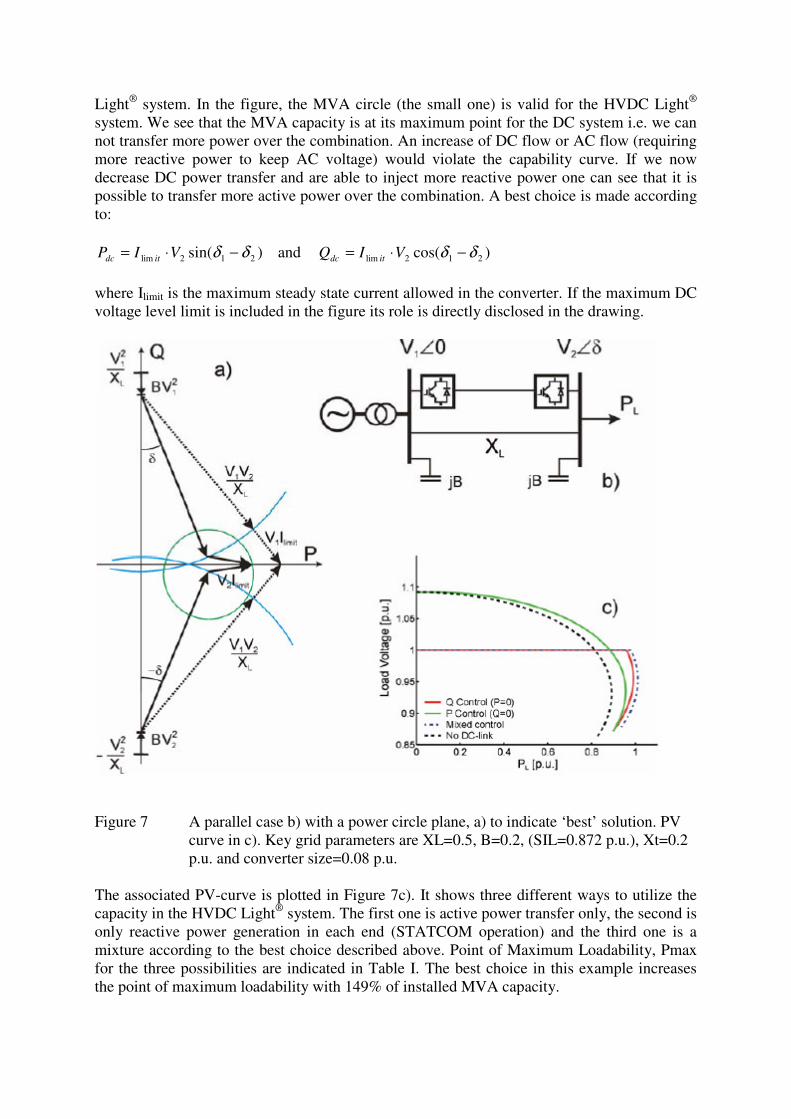
Light® system. In the figure, the MVA circle (the small one) is valid for the HVDC Light®
system. We see that the MVA capacity is at its maximum point for the DC system i.e. we cannot transfer more power over the combination. An increase of DC flow or AC flow (requiringmore reactive power to keep AC voltage) would violate the capability curve. If we nowdecrease DC power transfer and are able to inject more reactive power one can see that it ispossible to transfer more active power over the combination. A best choice is made accordingto:
)sin( 212lim δδ −⋅= VIP itdc and )cos( 212lim δδ −⋅= VIQ itdc
where Ilimit is the maximum steady state current allowed in the converter. If the maximum DCvoltage level limit is included in the figure its role is directly disclosed in the drawing.
Figure 7 A parallel case b) with a power circle plane, a) to indicate ‘best’ solution. PVcurve in c). Key grid parameters are XL=0.5, B=0.2, (SIL=0.872 p.u.), Xt=0.2p.u. and converter size=0.08 p.u.
The associated PV-curve is plotted in Figure 7c). It shows three different ways to utilize thecapacity in the HVDC Light® system. The first one is active power transfer only, the second isonly reactive power generation in each end (STATCOM operation) and the third one is amixture according to the best choice described above. Point of Maximum Loadability, Pmaxfor the three possibilities are indicated in Table I. The best choice in this example increasesthe point of maximum loadability with 149% of installed MVA capacity.
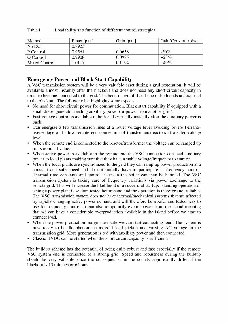
Table I Loadability as a function of different control strategies
Method Pmax [p.u.] Gain [p.u.] Gain/Converter sizeNo DC 0.8923P Control 0.9561 0.0638 -20%Q Control 0.9908 0.0985 +23%Mixed Control 1.0117 0.1194 +49%
Emergency Power and Black Start CapabilityA VSC transmission system will be a very valuable asset during a grid restoration. It will beavailable almost instantly after the blackout and does not need any short circuit capacity inorder to become connected to the grid. The benefits will differ if one or both ends are exposedto the blackout. The following list highlights some aspects:• No need for short circuit power for commutation. Black start capability if equipped with a
small diesel generator feeding auxiliary power (or power from another grid).• Fast voltage control is available in both ends virtually instantly after the auxiliary power is
back.• Can energize a few transmission lines at a lower voltage level avoiding severe Ferranti-
overvoltage and allow remote end connection of transformers/reactors at a safer voltagelevel.
• When the remote end is connected to the reactor/transformer the voltage can be ramped upto its nominal value.
• When active power is available in the remote end the VSC connection can feed auxiliarypower to local plants making sure that they have a stable voltage/frequency to start on.
• When the local plants are synchronized to the grid they can ramp up power production at aconstant and safe speed and do not initially have to participate in frequency control.Thermal time constants and control issues in the boiler can then be handled. The VSCtransmission system is taking care of frequency variations via power exchange to theremote grid. This will increase the likelihood of a successful startup. Islanding operation ofa single power plant is seldom tested beforehand and the operation is therefore not reliable.The VSC transmission system does not have thermal/mechanical systems that are affectedby rapidly changing active power demand and will therefore be a safer and tested way touse for frequency control. It can also temporarily export power from the island meaningthat we can have a considerable overproduction available in the island before we start toconnect load.
• When the power production margins are safe we can start connecting load. The system isnow ready to handle phenomena as cold load pickup and varying AC voltage in thetransmission grid. More generation is fed with auxiliary power and then connected.
• Classic HVDC can be started when the short circuit capacity is sufficient.
The buildup scheme has the potential of being quite robust and fast especially if the remoteVSC system end is connected to a strong grid. Speed and robustness during the buildupshould be very valuable since the consequences in the society significantly differ if theblackout is 15 minutes or 6 hours.

An example - Cross Sound HVDC Light®
The Cross Sound Cable (CSC) provides a directly controllable merchant interconnectionbetween the New England and Long Island systems in parallel to the congested New YorkCity transmission network.
Figure 8. The Cross Sound Cable feeding Long Island, New York
The interconnection is rated 330MW, ± 150 kV. The 40 km submarine cable is buried on thesea bottom. The Cross Sound Cable increases regional reliability by increasing the ability ofthe New England and New York networks to share generating capacity. It can also reduce theoverall cost of power to consumers as well as reduce overall CO2 emissions by allowing theshared use of more efficient generation units. The attributes of HVDC Light® transmissionsimplify system operation and the interconnection’s interface with each regional system.
The two HVDC Light® power cables and the multi fiber optic cable were laid bundledtogether to minimize the impact on the seabed and to protect oysters, scallops and other livingspecies. The cables were buried six feet into the sea floor to give protection against fishinggear and ships’ anchors.
Figure 9. HVDC Light® station at New Haven
Testing of the Cross Sound Cable project was completed in August 2002. The big blackout inthe north-eastern states happened on August 14, 2003. During the blackout the Cross Soundtransmission became an important power supply route to Long Island when restoring thenetwork during the blackout. Some hours after the blackout, a federal order was given to startemergency operation. CSC was the first transmission link to Long Island that was put into

service after the blackout. In addition to providing power to Long Island, the AC voltagecontrol provided by the link of both Long Island and Connecticut networks showed that itcould keep the AC voltages constant during system faults. Thunderstorms that occurredbefore the networks were completely restored forced the CSC to several +100 to –70 Mvarswings over 20 seconds. The AC voltage was kept constant. The owner has concluded that thecable interconnection was a great part of the success of getting Long Island out of the dark,and restoring power. Millions of consumers in the New York area benefited from the quicknetwork rebound.
Figure 10. Actual power restoration build up from HVDC Light® converter station
After start of commercial operation the Cross Sound Cable has shown a consistent availability(scheduled and forced) of 98 %.
CONCLUSIONSHVDC Light® is a power system designed to transmit power underground and underwater. Itoffers numerous environmental benefits, such as no overhead lines, neutral electromagneticfields, oil-free cables and compact converter stations. These benefits make new transmissionprojects in densely populated areas acceptable for the public.
For the power system engineer the HVDC Light® technology offers a number of additionalbenefits such as:
- Independent active/reactive power control- Black start capability- Power stability benefits
An example from real life has shown that the HVDC Light® system worked as planned duringa blackout situation and was a key factor for fast system restoration.
BIOGRAPHYStaffan Rudin (1965) has a Master Degree in Electrical Engineering from the Institute ofTechnology Lund, Sweden. Mr. Rudin has 15 years of experience in the Power T&D area.This includes development and design of both FACTS and HVDC systems. Mr Rudinpreviously held a position as Manager of the ABB FACTS System Design group in Sweden.His current position at ABB is Marketing Manager HVDC Light® & FACTS in China.
Guang Bai has a Master’s degree in Power System Reliability and a Bachelor’s degree inPower System Automation. He has six years working experience with Northeast China PowerDesign Institute. He joined ABB China in 2003 and now is working with the Power Gridbusiness.
Changchun Zhou got his Ph.D degree in Electrical Engineering from Zhejiang University,China. His research areas focus on HVDC and FACTS modeling and analysis. Mr Zhoujoined ABB Corporate Research in 2004 as a Senior Research Engineer, now he is workingon HVDC Light® modeling.
REFERENCES[1] www.abb.com/hvdc[2] S. G. Johansson, G Asplund, E Jansson, R Ruderwall “Power System Stability benefitswith VSC DC-Transmission Systems”, CIGRE