01 OWJ200101 WCDMA UTRAN Optimization Flow (With Comment) ISSUE1.0
75
www.huawei.com Copyright © 2006 Huawei Technologies Co., Ltd. All rights reserved. WCDMA UTRAN Optimization Flow
-
Upload
mohamed-abdel-monem -
Category
Documents
-
view
31 -
download
13
description
Optimization WCDMA
Transcript of 01 OWJ200101 WCDMA UTRAN Optimization Flow (With Comment) ISSUE1.0

www.huawei.com
Copyright © 2006 Huawei Technologies Co., Ltd. All rights reserved.
WCDMA UTRAN Optimization Flow
Page1Copyright © 2006 Huawei Technologies Co., Ltd. All rights reserved.
Foreword
� WCDMA optimization is a very important part in the life of
the network.
� Mainly, the optimization contents the preparation, single site
verification, RF optimization, parameters optimization.

Page2Copyright © 2006 Huawei Technologies Co., Ltd. All rights reserved.
Contents
1. Introduction of Optimization Flow
2. The preparation for the Optimization Project
3. Single Site Verification
4. RF Optimization
5. Parameters Optimization
6. Optimization Report
Page3Copyright © 2006 Huawei Technologies Co., Ltd. All rights reserved.
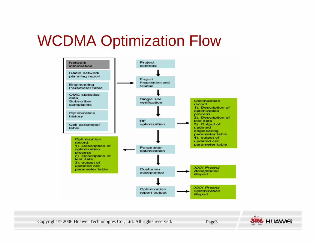
WCDMA Optimization Flow
Page4Copyright © 2006 Huawei Technologies Co., Ltd. All rights reserved.
Introduction of Optimization Flow
� Customized Document:
� Acceptance Report
� Optimization Report
� Site Configuration Parameter Table
� Radio Part Parameter configuration Table
� Process Document and Data:
� Site configuration Parameter Table
� Radio part Parameter configuration Table
Output document:
Page5Copyright © 2006 Huawei Technologies Co., Ltd. All rights reserved.
Contents
1. Introduction of Optimization Flow
2. The preparation for the Optimization Project
3. Single Site Verification
4. RF Optimization
5. Parameters Optimization
6. Optimization Report
Page6Copyright © 2006 Huawei Technologies Co., Ltd. All rights reserved.
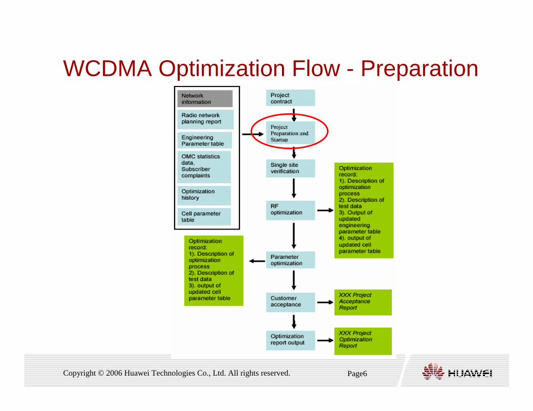
WCDMA Optimization Flow - Preparation

Page7Copyright © 2006 Huawei Technologies Co., Ltd. All rights reserved.
The Preparation for Projection
� The following work is required:
� Understanding of the Existing Network
� Cluster Division and Optimization Team Establishment
� Optimization Tools and Software
Page8Copyright © 2006 Huawei Technologies Co., Ltd. All rights reserved.
The Preparation for Projection
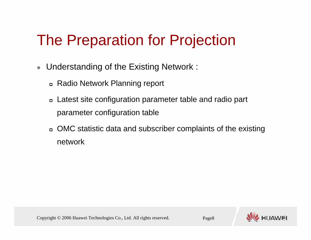
� Understanding of the Existing Network :
� Radio Network Planning report
� Latest site configuration parameter table and radio part
parameter configuration table
� OMC statistic data and subscriber complaints of the existing
network
Page9Copyright © 2006 Huawei Technologies Co., Ltd. All rights reserved.
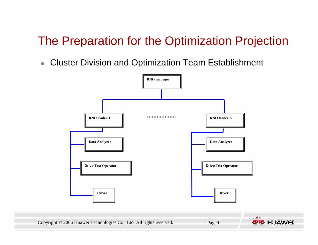
The Preparation for the Optimization Projection
� Cluster Division and Optimization Team Establishment
RNO leader-1
Data Analyzer
Drive Test Operator
Driver
RNO leader-n
Data Analyzer
Drive Test Operator
Driver
..................
RNO manager
Page10Copyright © 2006 Huawei Technologies Co., Ltd. All rights reserved.
The Preparation for Projection
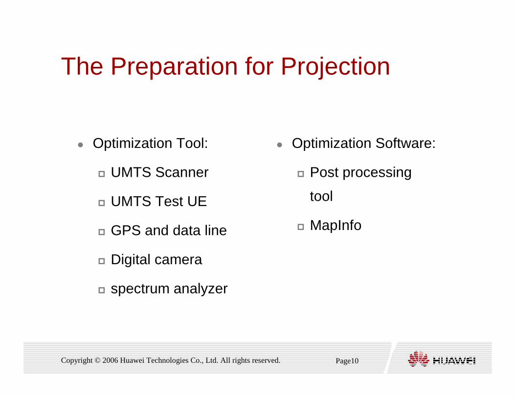
� Optimization Tool:
� UMTS Scanner
� UMTS Test UE
� GPS and data line
� Digital camera
� spectrum analyzer
� Optimization Software:
� Post processing
tool
� MapInfo
Page11Copyright © 2006 Huawei Technologies Co., Ltd. All rights reserved.
Contents
1. Introduction of Optimization Flow
2. The preparation for the Optimization Project
3. Single Site Verification
4. RF Optimization
5. Parameters Optimization
6. Optimization Report
Page12Copyright © 2006 Huawei Technologies Co., Ltd. All rights reserved.
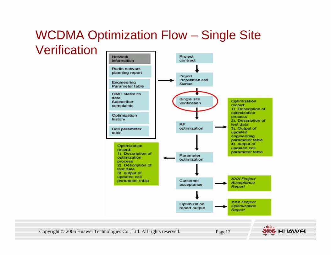
WCDMA Optimization Flow – Single Site Verification
Page13Copyright © 2006 Huawei Technologies Co., Ltd. All rights reserved.
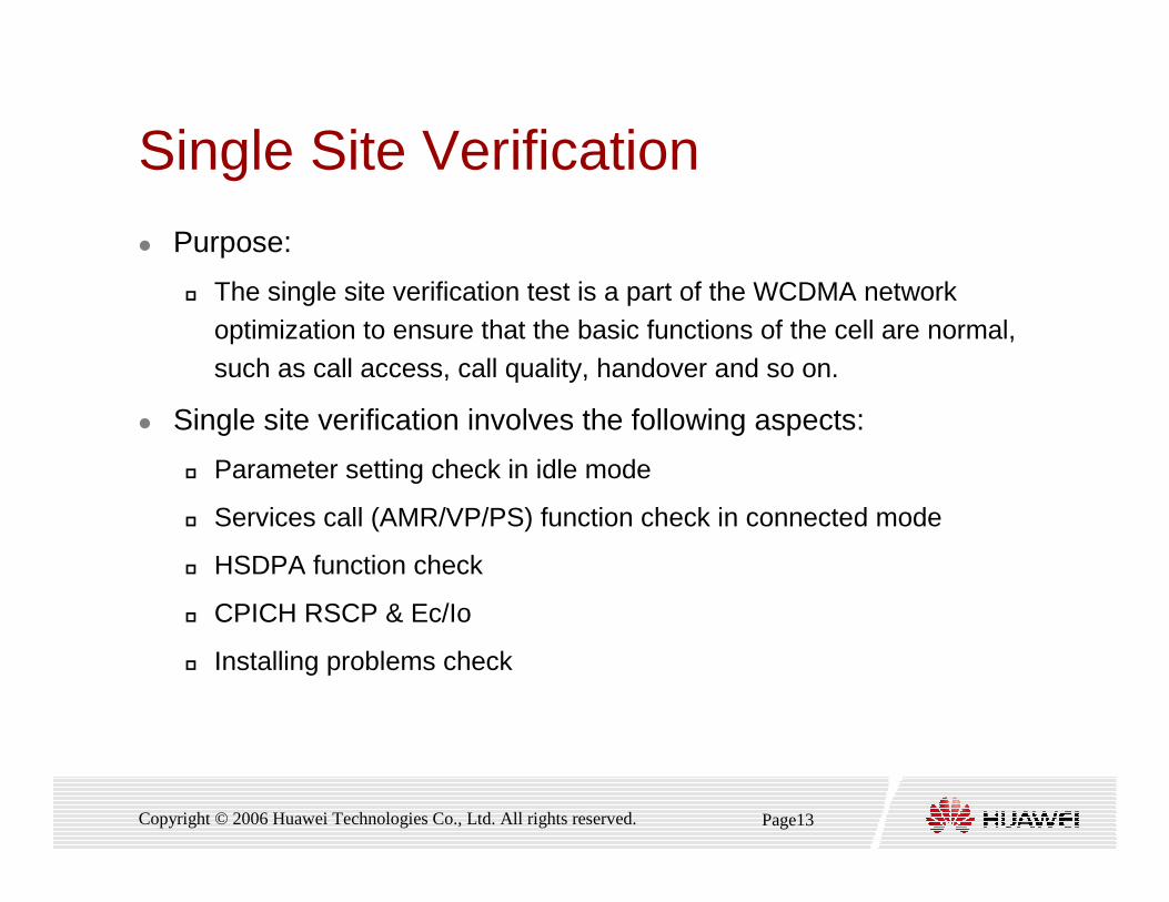
Single Site Verification
� Purpose:
� The single site verification test is a part of the WCDMA networkoptimization to ensure that the basic functions of the cell are normal,
such as call access, call quality, handover and so on.
� Single site verification involves the following aspects:
� Parameter setting check in idle mode
� Services call (AMR/VP/PS) function check in connected mode
� HSDPA function check
� CPICH RSCP & Ec/Io
� Installing problems check
Page14Copyright © 2006 Huawei Technologies Co., Ltd. All rights reserved.
Single Site Verification
� Single site verification includes :
� preparations before test
� single site test
� solving problems
� The single site verification is completed by:
� On-site engineers
� RNO engineers
Page15Copyright © 2006 Huawei Technologies Co., Ltd. All rights reserved.
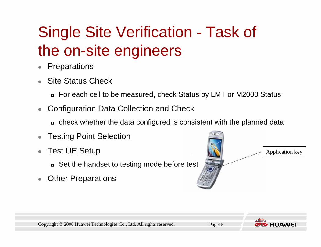
Single Site Verification - Task of the on-site engineers � Preparations
� Site Status Check
� For each cell to be measured, check Status by LMT or M2000 Status
� Configuration Data Collection and Check
� check whether the data configured is consistent with the planned data
� Testing Point Selection
� Test UE Setup
� Set the handset to testing mode before test
� Other Preparations
Application key

Page16Copyright © 2006 Huawei Technologies Co., Ltd. All rights reserved.
Single Site Verification - Task of the on-site engineers� Verification in Idle Mode
� Frequency Check
� Check whether the frequency number of the cell to be measured is consistent with the planned data
� Scramble Check
� Check whether the scramble configuration is consistent with the planned
configuration
� LAC/RAC Check
� Check whether the LAC/RAC of the cell to be measured is consistent with the planed one.
� CPICH_RSCP/CPICH_Ec/Io (Near Site) Test
� Check whether the CPICH RSCP and CPICH Ec/Io received by UE are greater
than the threshold
Page17Copyright © 2006 Huawei Technologies Co., Ltd. All rights reserved.
Single Site Verification - Task of the on-site engineers� Verification in connect Mode
� Originating and Terminating Connection Test of Voice Service
� Check whether the originating and terminating function of voice service function normally by call quality test
� Originating and Terminating Connection Test of VP Service
� Check whether the originating and terminating function of VP service function normally by call quality test
� Connection Test of PS Services
� Check whether the originating function of PS services are normal by handset online service
� Solving Problems
� If on-site engineers find product function problems or parameter configuration problems, the engineers must location them and retest until the problems are solved and process terminates.
Page18Copyright © 2006 Huawei Technologies Co., Ltd. All rights reserved.
Single Site Verification – Task of the RNO engineers� Preparations
� Cell Status Confirmation
� Before checking site, you need to inquiry product support
engineers whether the cell is in normal status
� Testing Route Selection
� Before test, you must select a proper testing route according to
site distribution and local environment
� Precautions
Page19Copyright © 2006 Huawei Technologies Co., Ltd. All rights reserved.
Single Site Verification – Task of the RNO engineers� Coverage DT Check
� Check whether CPICH RSCP and CPICH Ec/Io received by
scanner is normal
� Abnormal power amplifier
� Abnormal connection of antenna-feeder
� Inconsistency of antenna tile/direction angle from planned one
� Blocking by buildings
Page20Copyright © 2006 Huawei Technologies Co., Ltd. All rights reserved.
Single Site Verification – Task of the RNO engineers
� HSDPA Access Function Test
� To test HSDPA access function
� Check whether the antenna for receiving diversity signals is
reversely connected
� Fixed Maximum Transmit Power of UE, measure the RTWP of
the cells
� Checking Antennas by Exchanging Feeders

Page21Copyright © 2006 Huawei Technologies Co., Ltd. All rights reserved.
Single Site Verification – Task of the RNO engineers
� Antenna Diversity Check
� The method for UE to transmit signals at the fixed maximum
power is a recommended method of test and operation
� Solving Problems
� If RNO engineers find problems about product function, RNO
engineers must ask product support engineers to solve
problems
Page22Copyright © 2006 Huawei Technologies Co., Ltd. All rights reserved.
Single Site Verification
� Summarization:
� In single site verification stage, engineers check whether
equipment functions normally
� Single site verification is a basis for the following RF
optimization and service optimization
� If all verifications about function are accepted, the single site
verification is completed
� After single site verification, optimization comes to RF
optimization
Page23Copyright © 2006 Huawei Technologies Co., Ltd. All rights reserved.
Contents
1. Introduction of Optimization Flow
2. The preparation for the Optimization Project
3. Single Site Verification
4. RF Optimization
5. Parameters Optimization
6. Optimization Report
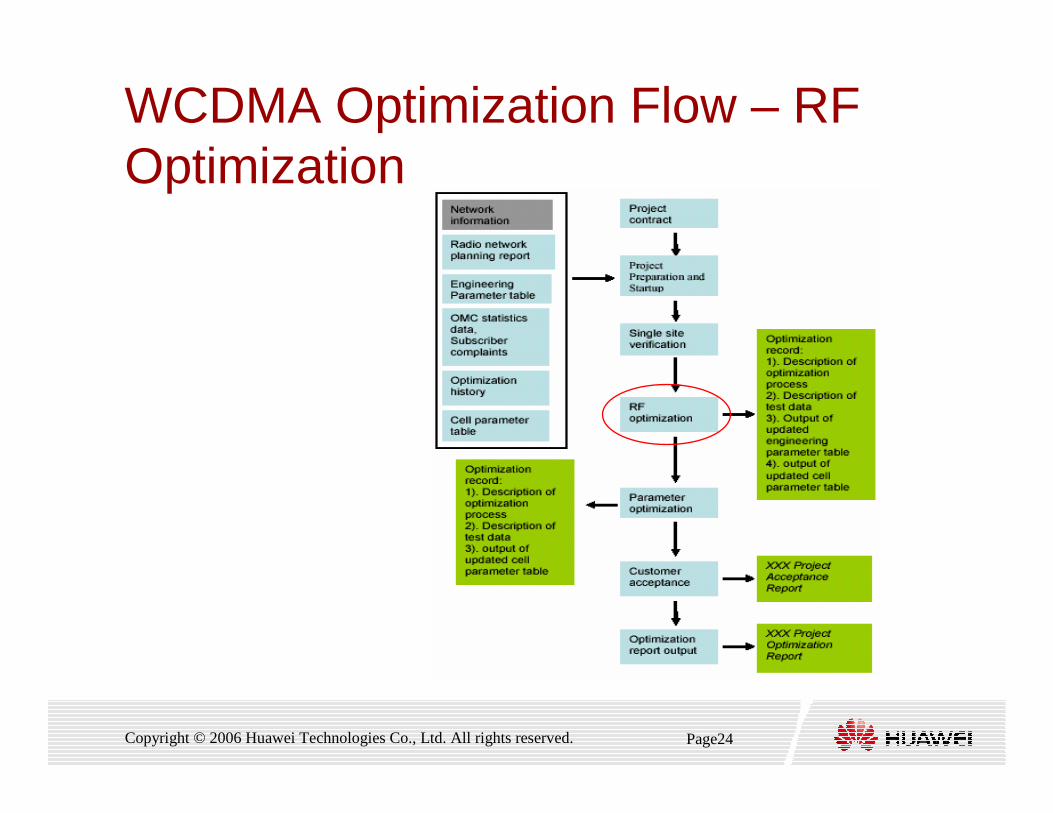
Page24Copyright © 2006 Huawei Technologies Co., Ltd. All rights reserved.
WCDMA Optimization Flow – RF Optimization
Page25Copyright © 2006 Huawei Technologies Co., Ltd. All rights reserved.
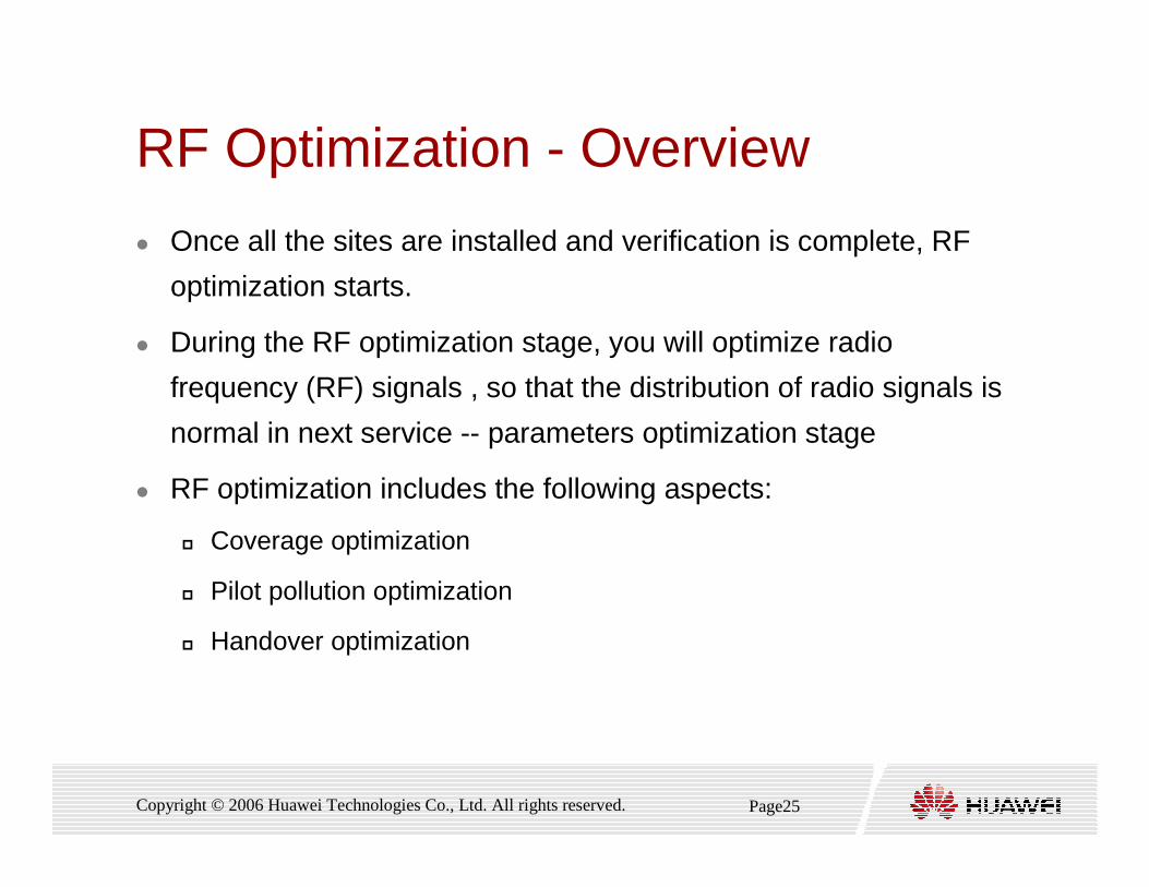
RF Optimization - Overview
� Once all the sites are installed and verification is complete, RF
optimization starts.
� During the RF optimization stage, you will optimize radio
frequency (RF) signals , so that the distribution of radio signals is
normal in next service -- parameters optimization stage
� RF optimization includes the following aspects:
� Coverage optimization
� Pilot pollution optimization
� Handover optimization

Page26Copyright © 2006 Huawei Technologies Co., Ltd. All rights reserved.
RF Optimization flow

Page27Copyright © 2006 Huawei Technologies Co., Ltd. All rights reserved.
RF Optimization - Preparation (1)� Deciding Optimization target
� Weak coverage
� Pilot pollution
� High SHO Factor based on DT
� Dividing Clusters
� Deciding Test Route
� Confirm the KPI DT acceptance route with the operator before
DT
� Preparing Tools and Data
� Preparing Software
� Preparing Hardware
� Preparing Data
Page28Copyright © 2006 Huawei Technologies Co., Ltd. All rights reserved.
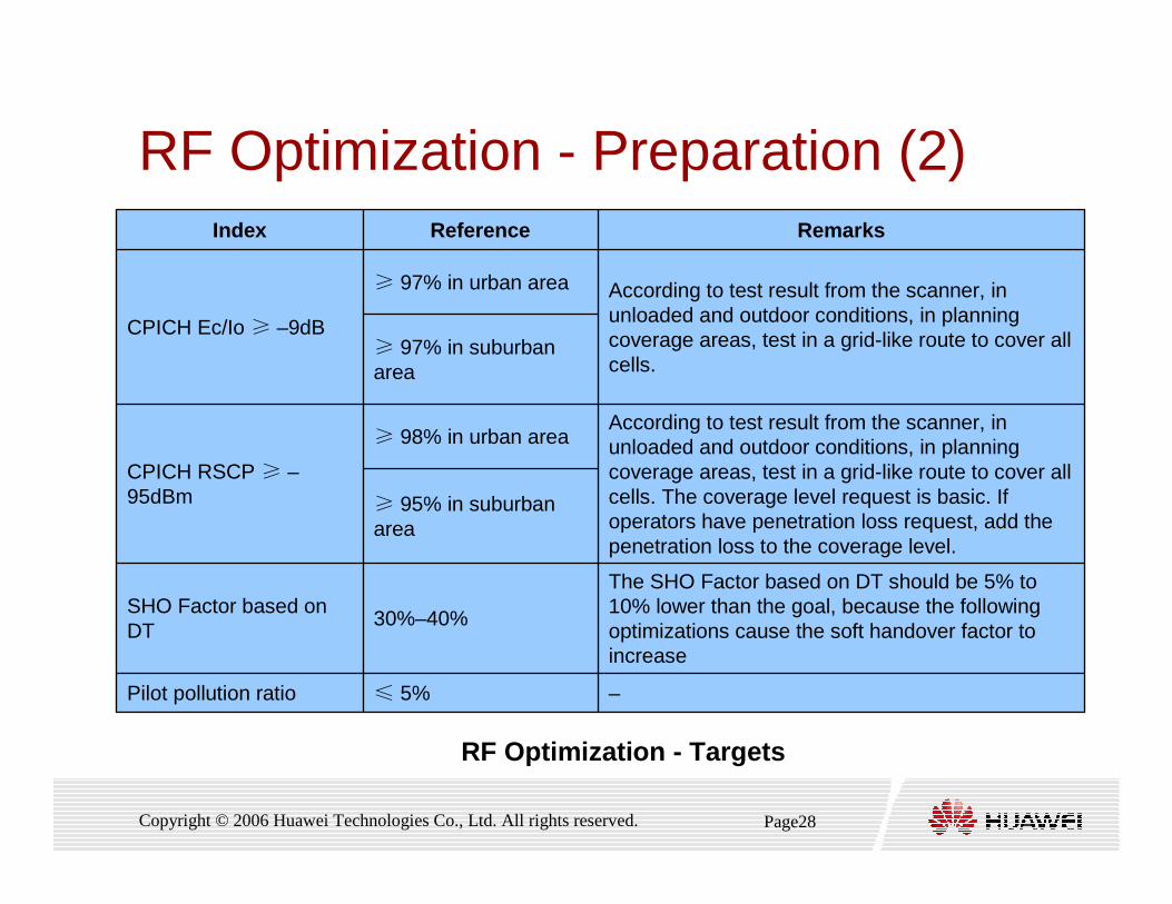
RF Optimization - Preparation (2)
–≤ 5%Pilot pollution ratio
The SHO Factor based on DT should be 5% to 10% lower than the goal, because the following optimizations cause the soft handover factor to increase
30%–40%SHO Factor based on DT
≥ 95% in suburban area
According to test result from the scanner, in unloaded and outdoor conditions, in planning coverage areas, test in a grid-like route to cover all cells. The coverage level request is basic. If operators have penetration loss request, add the penetration loss to the coverage level.
≥ 98% in urban area
CPICH RSCP ≥ –95dBm
≥ 97% in suburban area
According to test result from the scanner, in unloaded and outdoor conditions, in planning coverage areas, test in a grid-like route to cover all cells.
≥ 97% in urban area
CPICH Ec/Io ≥ –9dB
RemarksReferenceIndex
RF Optimization - Targets

Page29Copyright © 2006 Huawei Technologies Co., Ltd. All rights reserved.
RF Optimization - Preparation (3)
� Dividing Clusters
� RF optimization must be performed on a group of or a cluster
of NodeBs ,This ensures that interference from intra-frequency
neighbor cells are considered during optimization.
� Dividing clusters involves approval by the operator.
� Deciding Test Route
� The KPI DT acceptance route is the core route of RF
optimization test routes. Its optimization is the core of RF
optimization.
Page30Copyright © 2006 Huawei Technologies Co., Ltd. All rights reserved.
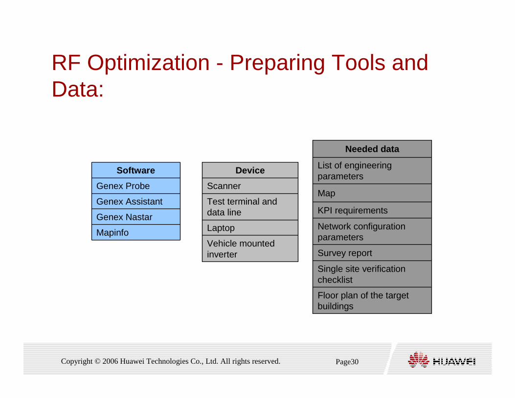
RF Optimization - Preparing Tools and Data:
Mapinfo
Genex Nastar
Genex Assistant
Genex Probe
Software
Vehicle mounted inverter
Laptop
Test terminal and data line
Scanner
Device
Floor plan of the target buildings
Single site verification checklist
Survey report
Network configuration parameters
KPI requirements
Map
List of engineering parameters
Needed data
Page31Copyright © 2006 Huawei Technologies Co., Ltd. All rights reserved.
RF Optimization - Data Collection
� During RF optimization stage, the key is the optimization of radio
signals distribution, with the major means of DT and indoor test
� DT is a major test. Collect scanner and UE data of radio signals
by DT test
� Usually the DT and indoor test during RF optimization stage is
based on VP service.
� During RF optimization stage, collect neighbor cell data of network
optimization and other data configured in RNC database

Page32Copyright © 2006 Huawei Technologies Co., Ltd. All rights reserved.
RF Optimization - RF problem solutions
� Antenna tilt
� Antenna azimuth
� Antenna location
� Split sector
� Remove sector
� Combine sector
� Antenna height
� Antenna type
� TMA
� RRU
� Site location
� New site
Page33Copyright © 2006 Huawei Technologies Co., Ltd. All rights reserved.
RF Optimization
� Attention:
� During the RF optimization ,sometimes the problems can be
resolved completely by proper adjustment, but there is also
some disadvantages of the RF optimization
� The duration of the RF Optimization will be always very long
� Some adjustment is difficult to implement
� If the problems are not resolved by the RF optimization, it is
difficult to recover the antennas back to the former
conditions
h1

Slide 34
h1 考虑删除hw, 12/2/2006
Page34Copyright © 2006 Huawei Technologies Co., Ltd. All rights reserved.
RF Optimization
� Some advices:
� Before the RF adjusting, we’d better survey the relative sites,
and give some applicable advice
� If possible, do the RF adjustment and test the effect at the
same time
Page35Copyright © 2006 Huawei Technologies Co., Ltd. All rights reserved.
RF Coverage Problem Analysis
� Coverage problem analysis is key to RF optimization. It
involves signal distribution. The coverage problems to be
analyzed include:
� Weak coverage
� Overshoot coverage
� Unbalance between uplink and downlink
� No primary pilot cell
Page36Copyright © 2006 Huawei Technologies Co., Ltd. All rights reserved.
RF Coverage Problem Analysis
� Coverage Analysis Processes:
� Downlink Coverage Analysis
� Analyzing Pilot Coverage Strength
� Analyzing Pilot Coverage quality
� Analyzing Primary Pilot Cell
� Analyzing comparison of UE and Scanner Coverage
� Uplink Coverage Analysis
� Analyzing Uplink Interference
� Analyzing distribution of UE Transmit Power
Page37Copyright © 2006 Huawei Technologies Co., Ltd. All rights reserved.
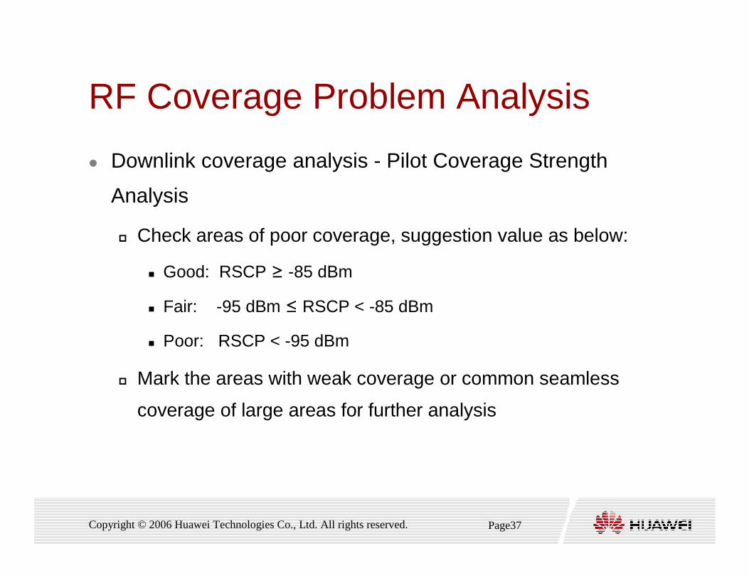
RF Coverage Problem Analysis
� Downlink coverage analysis - Pilot Coverage Strength
Analysis
� Check areas of poor coverage, suggestion value as below:
� Good: RSCP ≥ -85 dBm
� Fair: -95 dBm ≤ RSCP < -85 dBm
� Poor: RSCP < -95 dBm
� Mark the areas with weak coverage or common seamless
coverage of large areas for further analysis
Page38Copyright © 2006 Huawei Technologies Co., Ltd. All rights reserved.
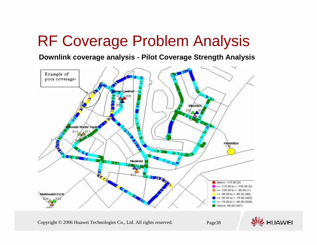
RF Coverage Problem AnalysisDownlink coverage analysis - Pilot Coverage Strength Analysis

Page39Copyright © 2006 Huawei Technologies Co., Ltd. All rights reserved.
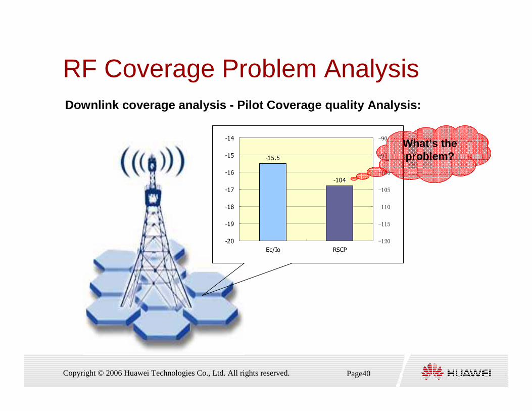
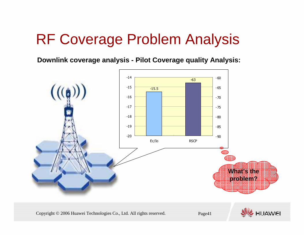
RF Coverage Problem Analysis
� Downlink coverage analysis - Pilot Coverage quality
Analysis
� Ec/Io plot should also be analysed based on the thresholds :
� Good: Ec/Io ≥ -8 dB
� Fair: -14 dB ≤ Ec/Io < -8 dB
� Poor: Ec/Io < - 14 dB
� Areas of poor Ec/Io should be highlighted for further
investigation
Page40Copyright © 2006 Huawei Technologies Co., Ltd. All rights reserved.
RF Coverage Problem Analysis
-15.5
-104
-20
-19
-18
-17
-16
-15
-14
Ec/Io RSCP
-120
-115
-110
-105
-100
-95
-90 What’s the problem?
Downlink coverage analysis - Pilot Coverage quality A nalysis:
Page41Copyright © 2006 Huawei Technologies Co., Ltd. All rights reserved.
RF Coverage Problem Analysis
-15.5
-63
-20
-19
-18
-17
-16
-15
-14
Ec/Io RSCP
-90
-85
-80
-75
-70
-65
-60
What’s the problem?
Downlink coverage analysis - Pilot Coverage quality A nalysis:
Page42Copyright © 2006 Huawei Technologies Co., Ltd. All rights reserved.
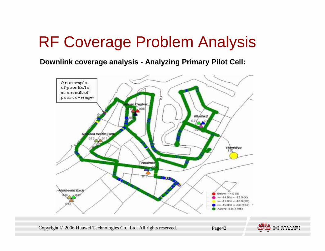
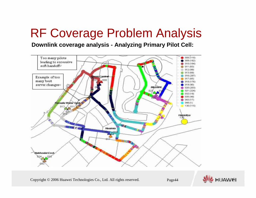
RF Coverage Problem AnalysisDownlink coverage analysis - Analyzing Primary Pilot Cell:
Page43Copyright © 2006 Huawei Technologies Co., Ltd. All rights reserved.
RF Coverage Problem Analysis
� Downlink coverage analysis - Analyzing Primary Pilot Cell:
� Cell primary pilot analysis is analyzing cell scramble
information obtained in DT
� The content to be checked include :
� Weak coverage cell
� Cross-cell coverage cell
� No primary pilot cell
Page44Copyright © 2006 Huawei Technologies Co., Ltd. All rights reserved.
RF Coverage Problem AnalysisDownlink coverage analysis - Analyzing Primary Pilot Cell:
Page45Copyright © 2006 Huawei Technologies Co., Ltd. All rights reserved.
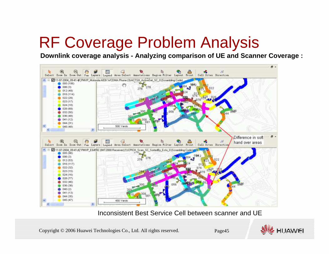
RF Coverage Problem AnalysisDownlink coverage analysis - Analyzing comparison of UE and Scanner Coverage :
Inconsistent Best Service Cell between scanner and UE
Page46Copyright © 2006 Huawei Technologies Co., Ltd. All rights reserved.
RF Coverage Problem Coverage Problem AnalysisAnalysis
� Uplink coverage analysis is analyzing UE transmit power obtained in DT.
� The quality standards of UE transmit power must be combined with optimization
standards.
� Assume the optimization indexes of UE transmit power as below:
The test result of voice service by test handset. Assume the maximum transmit power of UE is 21 dBm
>= 95%UE_Tx_Power≤ 10 dBm
� The defined corresponding quality standards are:
� Good if UE_Tx_Power ≤ 0 dBm
� Fair if 0 dBm < UE_Tx_Power ≤ 10 dBm
� Poor if UE_Tx_Power > 10 dBm
Uplink coverage analysis:
Page47Copyright © 2006 Huawei Technologies Co., Ltd. All rights reserved.
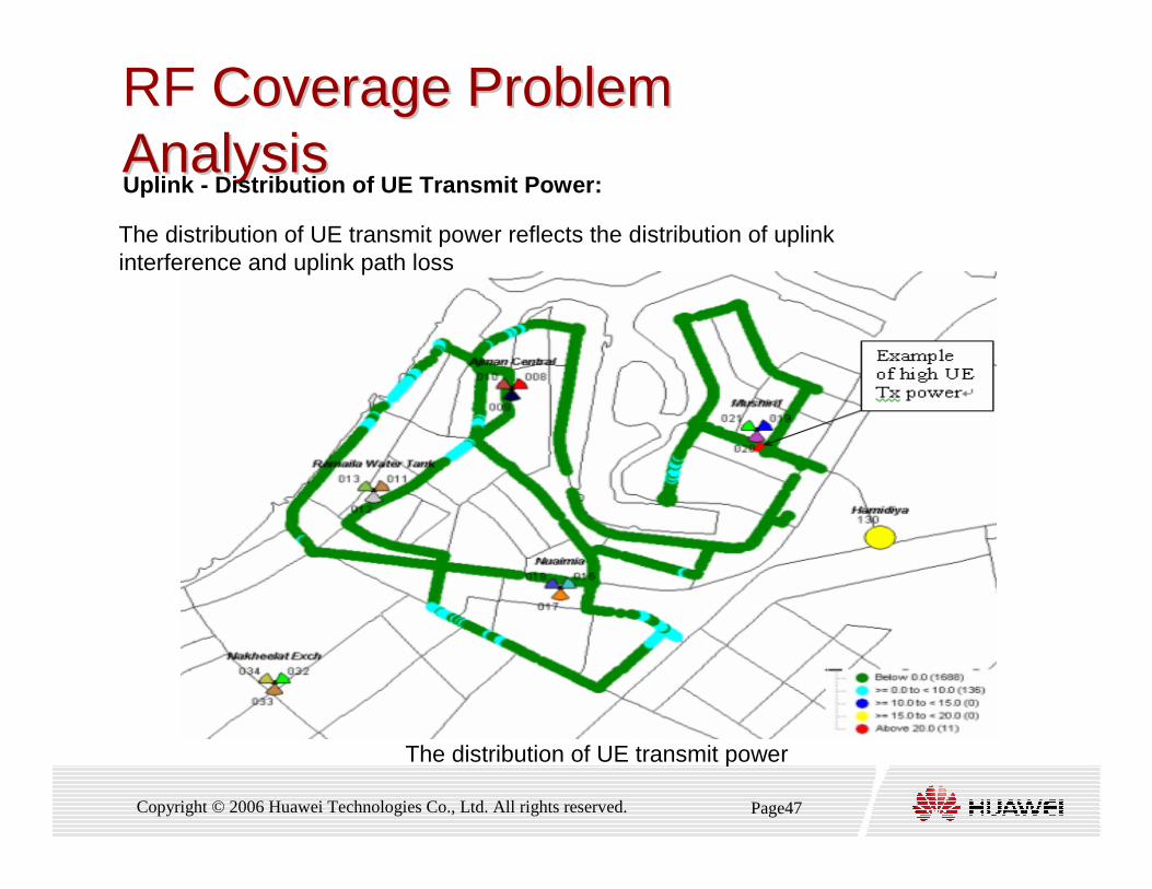
RF Coverage Problem Coverage Problem AnalysisAnalysisUplink - Distribution of UE Transmit Power:
The distribution of UE transmit power reflects the distribution of uplink interference and uplink path loss
The distribution of UE transmit power
Page48Copyright © 2006 Huawei Technologies Co., Ltd. All rights reserved.
Pilot Pollution Problem Analysis
� Pilot Pollution Point Definition:
� The pilot pollution is that excessive strong pilots exist in a point
but no primary pilot is strong enough
� Pilot pollution exists if all the following conditions are met:
� The number of pilots that meet the following condition is more than
4 and CPICH_RSCP > -100dBm
� (CPICH_RSCP1st - CPICH_RSCP 4th)< 5dB

Page49Copyright © 2006 Huawei Technologies Co., Ltd. All rights reserved.
Pilot Pollution Problem Pilot Pollution Problem AnalysisAnalysis
-62 -63 -64 -66 -67
-81
-90
-85
-80
-75
-70
-65
-60
SC1 SC2 SC3 SC4 SC5 SC6
RS
CP
(dB
m)
Active Set Pilot Pollution
Margin
NotPilot Pollution
Pilot Pollution Definition - Judgment Standards :
Page50Copyright © 2006 Huawei Technologies Co., Ltd. All rights reserved.
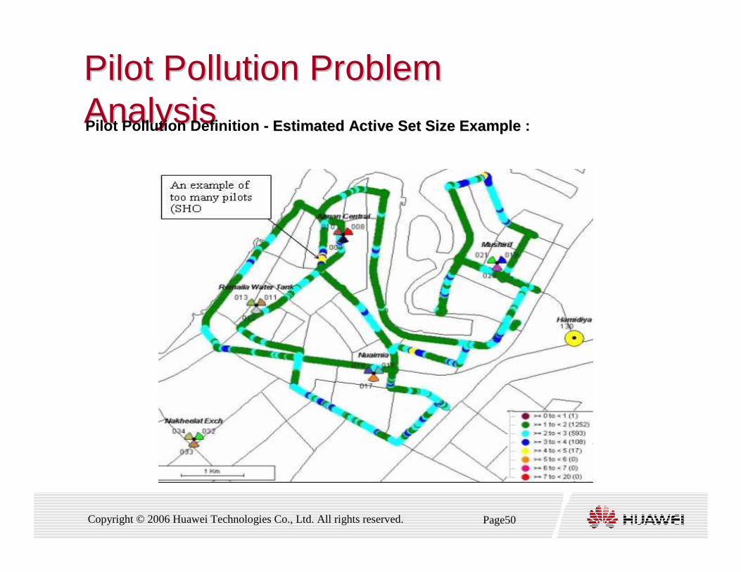
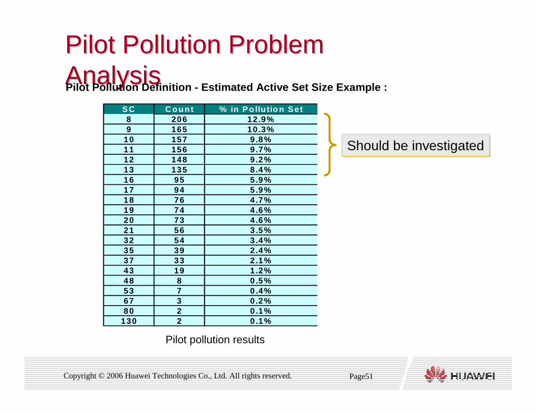
Pilot Pollution Problem Pilot Pollution Problem AnalysisAnalysisPilot Pollution Definition - Estimated Active Set Size Example Estimated Active Set Size Example :
Page51Copyright © 2006 Huawei Technologies Co., Ltd. All rights reserved.
Pilot Pollution Problem Pilot Pollution Problem AnalysisAnalysis
S C C o un t % in P o llu tio n S et8 206 12.9%9 165 10.3%
10 157 9.8%11 156 9.7%12 148 9.2%13 135 8.4%16 95 5.9%17 94 5.9%18 76 4.7%19 74 4.6%20 73 4.6%21 56 3.5%32 54 3.4%35 39 2.4%37 33 2.1%43 19 1.2%48 8 0.5%53 7 0.4%67 3 0.2%80 2 0.1%
130 2 0.1%
Should be investigatedShould be investigated
Pilot Pollution Definition - Estimated Active Set Si ze Example :
Pilot pollution results
Page52Copyright © 2006 Huawei Technologies Co., Ltd. All rights reserved.
Pilot Pollution Problem Analysis
� Causes of Pilot Pollution :
� Improper Cell Distribution
� Over High NodeB or Highly-mounted Antenna
� Improper Antenna Azimuth
� Improper Antenna Down Tilt
� Improper PICH Power
� Ambient Factors

Page53Copyright © 2006 Huawei Technologies Co., Ltd. All rights reserved.
Pilot Pollution Problem Analysis
� Influence of Pilot Pollution :
� Pilot pollution causes the following network problems:
� Ec/Io Deterioration
� Call Drop Due to Handover
� Capacity Decline

Page54Copyright © 2006 Huawei Technologies Co., Ltd. All rights reserved.
Pilot Pollution Problem Analysis
� Process for Analyzing Pilot Pollution
� Analyze scanner-based RSCP for 1st Best Service Cell and
Ec/Io for 1st Best Service Cell
� Analyze scanner-based Whole PP
� Locate the cells that cause pilot pollution of the key areas.
� Judge whether the pilot pollution is caused by existence of
multiple strong pilots or lack of a strong pilot
� Confirm the cells that need eliminating the coverage of an area
and that need enhancing the coverage of an area
� Retest after adjustment
Page55Copyright © 2006 Huawei Technologies Co., Ltd. All rights reserved.
Pilot Pollution Problem Analysis
� Solutions of Pilot Pollution :
� Antenna Adjustment
� PCPICH Power Adjustment
� Using RRU or Micro Cells
Page56Copyright © 2006 Huawei Technologies Co., Ltd. All rights reserved.
Handover Problem Analysis
� By adjusting RF parameters ,we can Control the size and location
of handover areas ,then we can eliminate handover call drop due
to sharp fluctuation and increase handover success rate.
� During RF optimization stage, the involved handover problem
include:
� Neighbor cell optimization
� Controlling SHO Factor based on DT

Page57Copyright © 2006 Huawei Technologies Co., Ltd. All rights reserved.
Handover Problem Analysis -Neighbor cell optimization � During RF optimization stage, missing neighbor cell is a key problem. The
neighbor cell optimization includes adding and removing neighbor cells
� Add: Missing neighbors
� Remove: These neighbors that were not measured but are in the neighbor list.
Careful consideration is needed prior to removing n eighbours
� Neighbor cell optimization can be analyzed by :
� Scanner Data
� UE Data Analysis
Page58Copyright © 2006 Huawei Technologies Co., Ltd. All rights reserved.
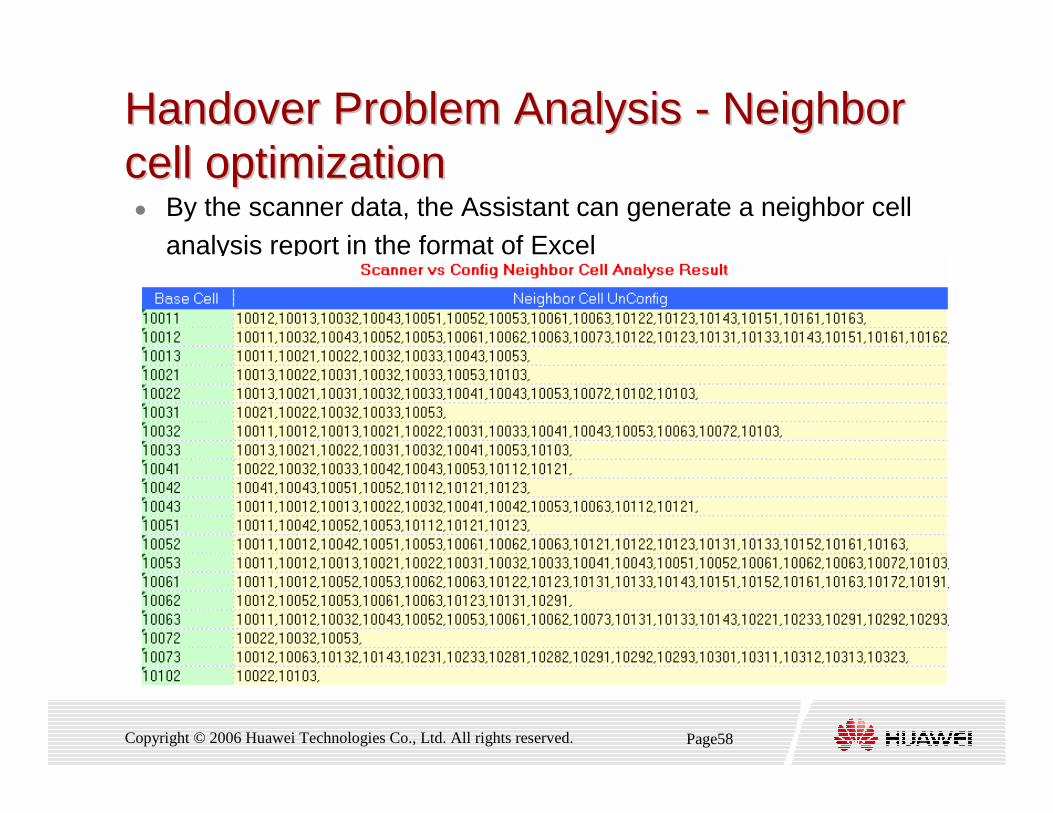
Handover Problem Analysis Handover Problem Analysis -- Neighbor Neighbor cell optimizationcell optimization� By the scanner data, the Assistant can generate a neighbor cell
analysis report in the format of Excel
Page59Copyright © 2006 Huawei Technologies Co., Ltd. All rights reserved.
Handover Problem Analysis - Neighbor cell optimization
� We can also analyze a missing neighbor cell by UE DT data
� The daemon analysis tool can seldom analyze UE data
automatically and generate missing neighbor cells
� but we can Compare the active set Ec/Io distribution
diagram measured by UE and that measured by scanner
� The spots with missing neighbor cells has a poor Ec/Io
measured by UE and a strong Ec/Io scanned by scanner .
Page60Copyright © 2006 Huawei Technologies Co., Ltd. All rights reserved.
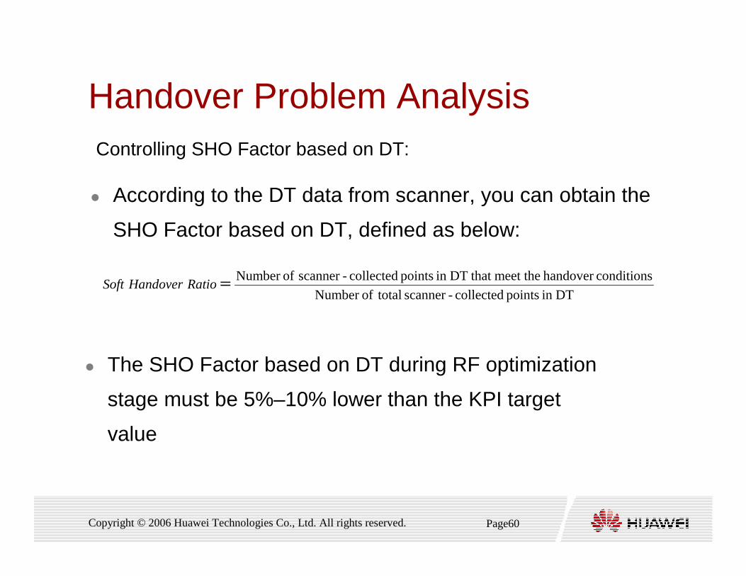
Handover Problem Analysis
� According to the DT data from scanner, you can obtain the
SHO Factor based on DT, defined as below:
Controlling SHO Factor based on DT:
DTin points collected-scanner totalofNumber
conditionshandover meet the that DTin points collected-scanner ofNumber =RatioHandoverSoft
� The SHO Factor based on DT during RF optimization
stage must be 5%–10% lower than the KPI target
value

Page61Copyright © 2006 Huawei Technologies Co., Ltd. All rights reserved.
Handover Problem Analysis� UE SHO Performance
� The success rates for event 1a, 1b & 1c and can be obtained
from softwareNumber of Active Set UpdatesNumber of Active Set Updates
Event CountEvent 1a - 328Event 1b - 306Event 1c - 64
Number of Active Set Update CompletesNumber of Active Set Update Completes
Event CountEvent 1a - 326Event 1b - 305Event 1c - 62
Soft-Handover Success RateSoft-Handover Success Rate
Event RateEvent 1a - 99.4Event 1b - 99.7Event 1c - 96.9
Page62Copyright © 2006 Huawei Technologies Co., Ltd. All rights reserved.
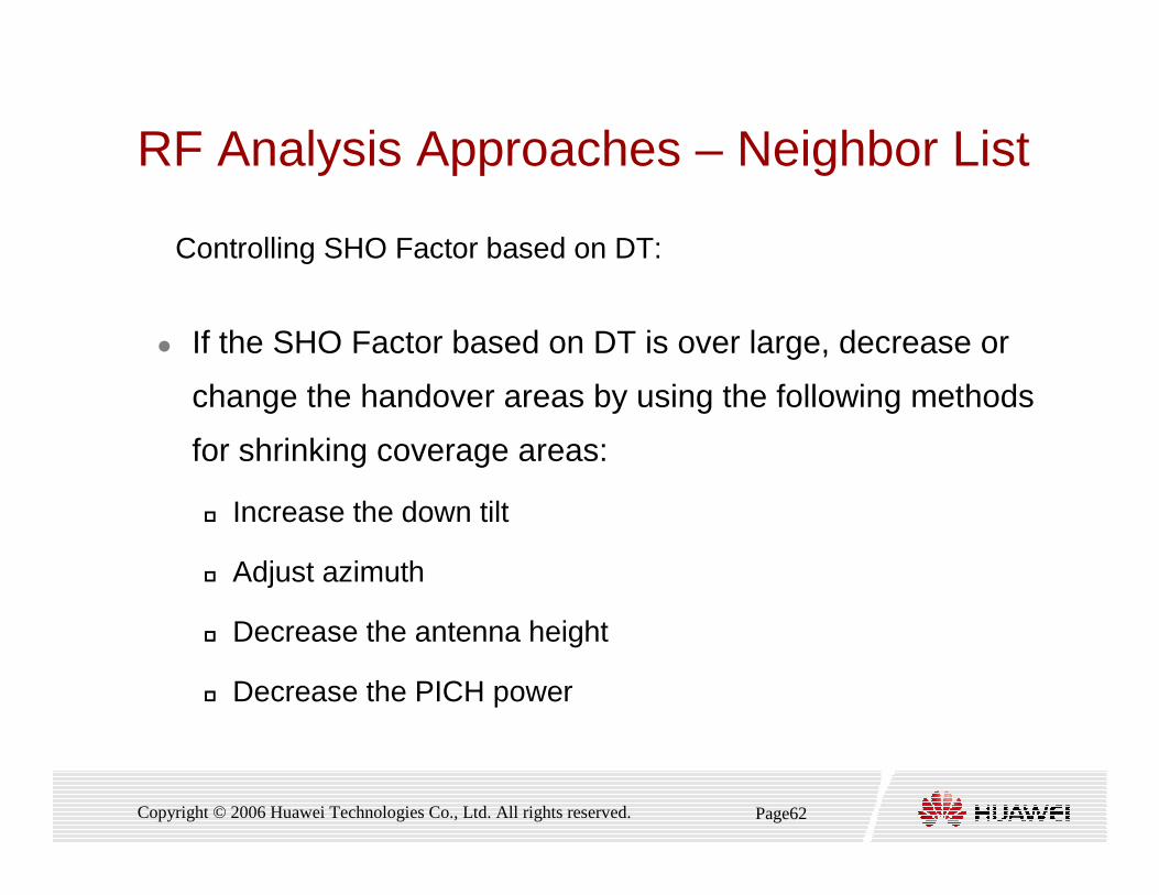
RF Analysis Approaches – Neighbor List
� If the SHO Factor based on DT is over large, decrease or
change the handover areas by using the following methods
for shrinking coverage areas:
� Increase the down tilt
� Adjust azimuth
� Decrease the antenna height
� Decrease the PICH power
Controlling SHO Factor based on DT:
Page63Copyright © 2006 Huawei Technologies Co., Ltd. All rights reserved.
Contents
1. Introduction of Optimization Flow
2. The preparation for the Optimization Project
3. Single Site Verification
4. RF Optimization
5. Parameters Optimization
6. Optimization Report
Page64Copyright © 2006 Huawei Technologies Co., Ltd. All rights reserved.
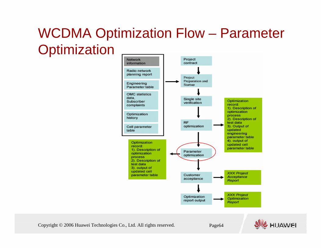
WCDMA Optimization Flow – ParameterOptimization
Page65Copyright © 2006 Huawei Technologies Co., Ltd. All rights reserved.
Purpose of Parameters Optimization
� Purpose of parameters optimization
� Decrease the access success ratio
� Decrease the call drop ratio
� Increase the quality of service
� The tools and data for analysis:
� scanner and UE
� RNC record data
� Statistic tools and KPI
� MSC & SGSN record if necessary

Page66Copyright © 2006 Huawei Technologies Co., Ltd. All rights reserved.
Drive test� The contents of drive test
� The call setup test for voice service
� The continuous call test for voice service
� Idle mode test
� The call setup test for video phone service
� The continuous call test for voice service
� The call setup test for PS service
� The continuous call test for PS service
The test should be performed repeatedly to the posi tion with The test should be performed repeatedly to the posi tion with problems to make sure that the problem is repeatabl e problems to make sure that the problem is repeatabl e
Page67Copyright © 2006 Huawei Technologies Co., Ltd. All rights reserved.
Drive Test Data Analysis
� Drive Test Data Analysis
� Analyzing and finding out the solution for access failure
� Analyzing and finding out the solution for drop call
� Analyzing and finding out the solution for service quality related
problems
Page68Copyright © 2006 Huawei Technologies Co., Ltd. All rights reserved.
Adjustment Recommendation and Implementation
� Adjustment Recommendation and Implementation
� Common Control Channel Power Allocation parameters
� RL Maximum Power parameters
� Intra-frequency Handover parameters
� Inter-frequency Handover parameters
� Inter-RAT Handover parameters
� Power Control parameters
� Access parameters
� Other related parameters
Page69Copyright © 2006 Huawei Technologies Co., Ltd. All rights reserved.
Test for Special Areas
� Special area refers to a small district or indoors environment
� Operator offices, residence of VIP
� Key hotels or entertainment location
� Government location
� Locations of large company or group subscribers
� Locations tend to be cared , such as railway station or airport

Page70Copyright © 2006 Huawei Technologies Co., Ltd. All rights reserved.
Contents
1. Introduction of Optimization Flow
2. The preparation for the Optimization Project
3. Single Site Verification
4. RF Optimization
5. Parameters Optimization
6. Optimization Report
Page71Copyright © 2006 Huawei Technologies Co., Ltd. All rights reserved.
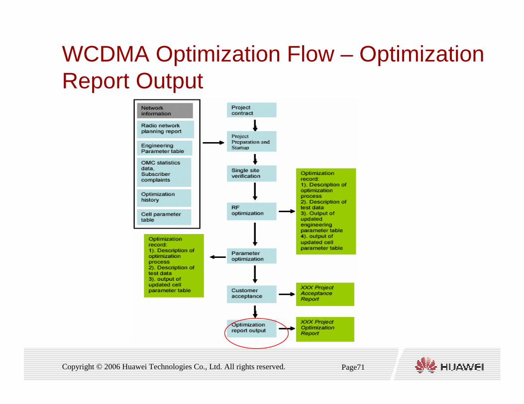
WCDMA Optimization Flow – OptimizationReport Output
Page72Copyright © 2006 Huawei Technologies Co., Ltd. All rights reserved.
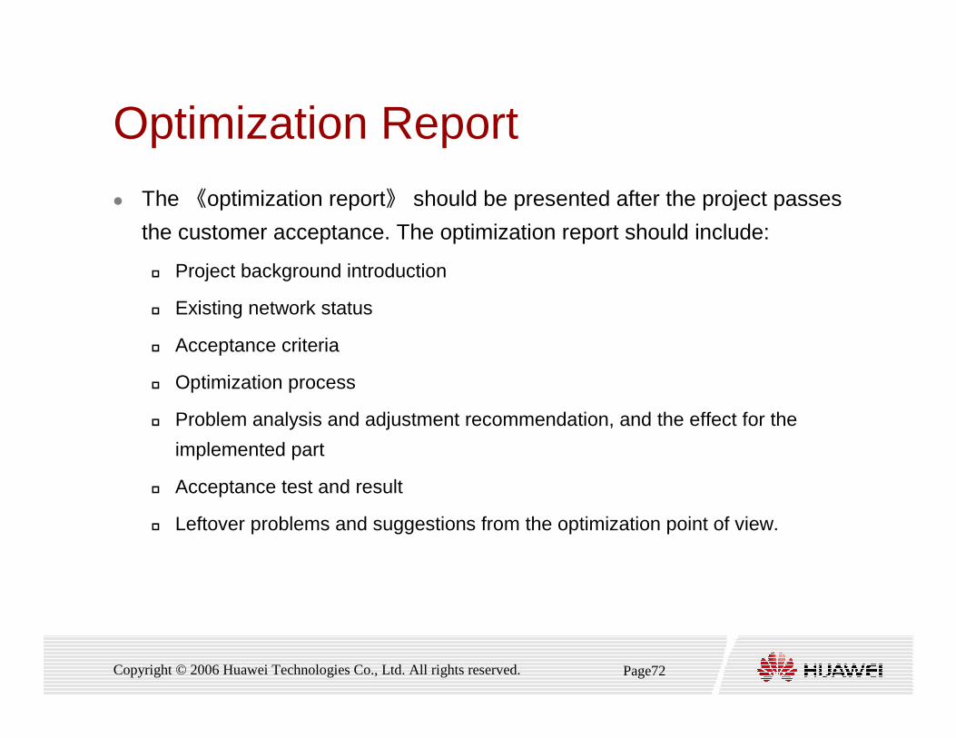
Optimization Report
� The 《optimization report》 should be presented after the project passes
the customer acceptance. The optimization report should include:
� Project background introduction
� Existing network status
� Acceptance criteria
� Optimization process
� Problem analysis and adjustment recommendation, and the effect for the
implemented part
� Acceptance test and result
� Leftover problems and suggestions from the optimization point of view.

Thank youwww.huawei.com