© PCS Limited: 2013 - Marine...
19
Transcript of © PCS Limited: 2013 - Marine...


© PCS Limited: 2013
Report
MORL substation
Proposed location
assessment
5 August 2013
PCS Document No: 6132/001/R/LM/01
Issue: A
Power Systems Project and Consultancy
Services (PCS) Ltd The Torus Building
Rankine Avenue
Scottish Enterprise Technology Park
East Kilbride
G75 0QF
Telephone: 01355 813322 (Office)
Fax: 01355 813320
Email: [email protected]
URL: www.pcs-scot.co.uk

MORL substation support Power Systems Project and Consultancy Services (PCS) Ltd
File: MORL substation support Page i
PCS Document No: 6132/001/R/LM/01 Issue: A
REPORT No: 6132/001/R/LM/01 ISSUE: A
TITLE: MORL substation support
SUMMARY EDP Renewables requested Power Systems Project and Consultancy Services (PCS) Ltd to
undertake an assessment of the grid connection options for a proposed new substation in the vicinity
of New Deer for the Moray Offshore windfarm The assessments undertaken by Power Systems PCS has identified a potential area to locate a new
grid connection substation based on the information available (though subject to the formal SSE
connection application/offer process),
• A preferred location to consider building a new substation would be close to the existing
OHL near Burnside (WSW of New Deer)
• The site would be required to accommodate a new 400kV GIS switchroon and a new
400/220kV OFTO substation compound.
• Approximate dimensions are estimated as :
o 80m x 80m for the SSE 400kV GIS compound
o 270m x 190m for OFTO 400/220kV AIS compound (AC option) o 340m x 200m for OFTO 400kV converter compound (DC option)
CLIENT: Damien McCool
ADDRESS: EDP Renewables
4th Floor, 40 Princes Street
Edinburgh
EH2 2BY
DISTRIBUTION: Final: Client 2 copies File: 1 copy DATE 5 August 2013
Name Job Title Signature
Prepared By N. Macdonald Electrical Engineer
Checked by J. Evans Senior Engineer
Authorised For Issue L. McCallum Director

MORL substation support Power Systems Project and Consultancy Services (PCS) Ltd
File: MORL substation support Page ii
PCS Document No: 6132/001/R/LM/01 Issue: A
AMENDMENT RECORD
Issue Date Issued Date Effective Purpose of Issue or
Description of Amendment
A 05/08/13 First Issue

MORL substation support Power Systems Project and Consultancy Services (PCS) Ltd
File: MORL substation support Page iii
PCS Document No: 6132/001/R/LM/01 Issue: A
TABLE OF CONTENTS
1 INTRODUCTION .................................................................................................................................. 1
2 AIM AND OBJECTIVES ....................................................................................................................... 2
2.1 AIM ................................................................................................................................................... 2
2.2 OBJECTIVES ....................................................................................................................................... 2
3 SCOPE OF WORK................................................................................................................................. 3
4 OVERVIEW OF SUBSTATION LOCATION AND DIMENSIONS .................................................... 4
4.1 LOCATION OF PREFERRED SITE………………………………………………………………………….5
4.2 PREFERRED CONNECTION VOLTAGE ................................................................................................... 6
5 GRID CONNECTION OPTIONS .......................................................................................................... 7
5.1 COMPOUND DIMENSIONS ........................................................................................................... 8
5.2 ROAD ACCESS OBSERVATIONS ......................................................................................................... 10
6 CONCLUSIONS AND RECOMMENDATIONS ................................................................................ 10
6.1 CONCLUSIONS ................................................................................................................................. 10
6.2 RECOMMENDATIONS ........................................................................................................................ 10
7 REFERENCE PHOTOGRAPHS ......................................................................................................... 11
MORL substation support Power Systems Project and Consultancy Services (PCS) Ltd
File: MORL substation support Page 1
PCS Document No: 6132/001/R/LM/01 Issue: A
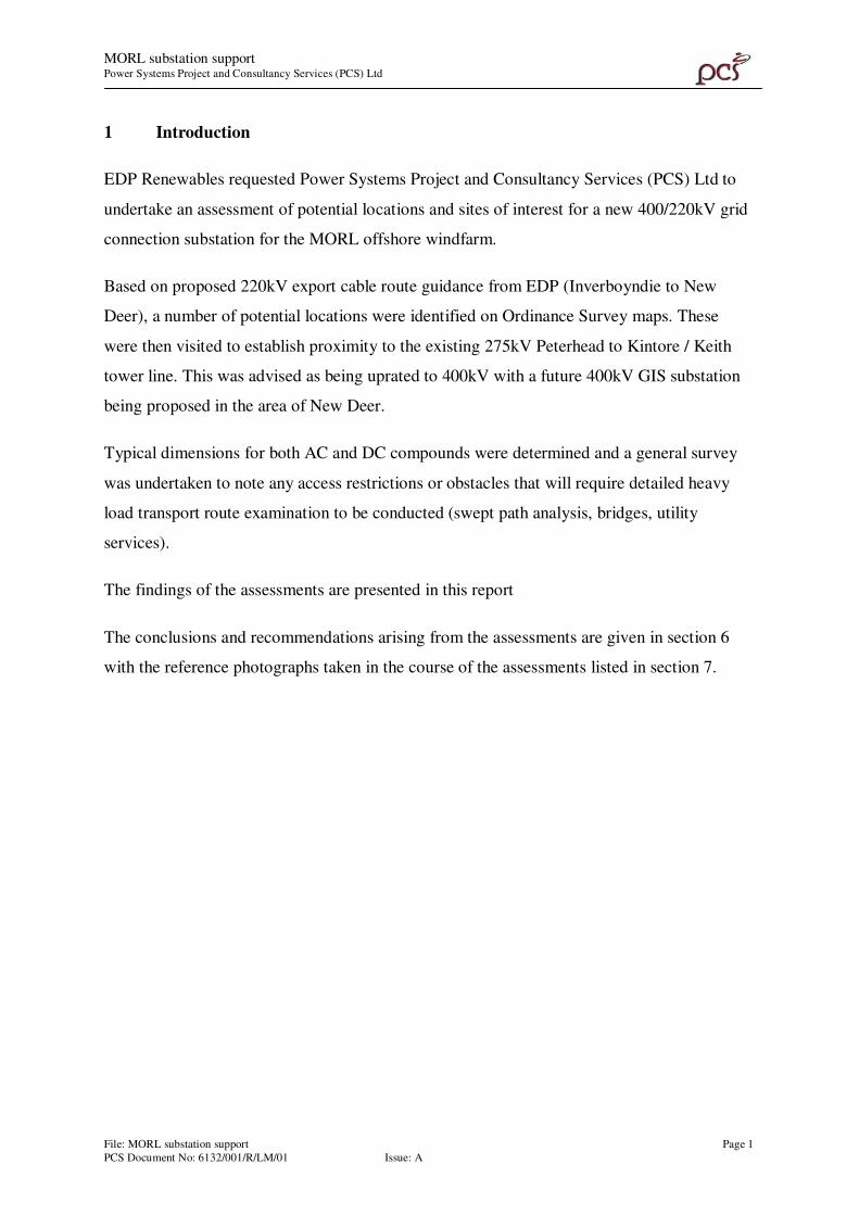
1 Introduction
EDP Renewables requested Power Systems Project and Consultancy Services (PCS) Ltd to
undertake an assessment of potential locations and sites of interest for a new 400/220kV grid
connection substation for the MORL offshore windfarm.
Based on proposed 220kV export cable route guidance from EDP (Inverboyndie to New
Deer), a number of potential locations were identified on Ordinance Survey maps. These
were then visited to establish proximity to the existing 275kV Peterhead to Kintore / Keith
tower line. This was advised as being uprated to 400kV with a future 400kV GIS substation
being proposed in the area of New Deer.
Typical dimensions for both AC and DC compounds were determined and a general survey
was undertaken to note any access restrictions or obstacles that will require detailed heavy
load transport route examination to be conducted (swept path analysis, bridges, utility
services).
The findings of the assessments are presented in this report
The conclusions and recommendations arising from the assessments are given in section 6
with the reference photographs taken in the course of the assessments listed in section 7.

MORL substation support Power Systems Project and Consultancy Services (PCS) Ltd
File: MORL substation support Page 2
PCS Document No: 6132/001/R/LM/01 Issue: A
2 Aim and Objectives
The aim and objectives of the assessments are outlined below.
2.1 Aim
The aim of the assessments was to provide an indication of the potential grid connection sites
and proposed the most suitable location able to accommodate the required compound areas.
2.2 Objectives
The objectives of the studies were:
i) Determine the size of compound required for both AC and DC options.
ii) Identify potential grid connection sites for the proposed substation.
iii) Assess the area surrounding the potential grid connection site for transporting
heavy loads from Peterhead.
MORL substation support Power Systems Project and Consultancy Services (PCS) Ltd
File: MORL substation support Page 3
PCS Document No: 6132/001/R/LM/01 Issue: A
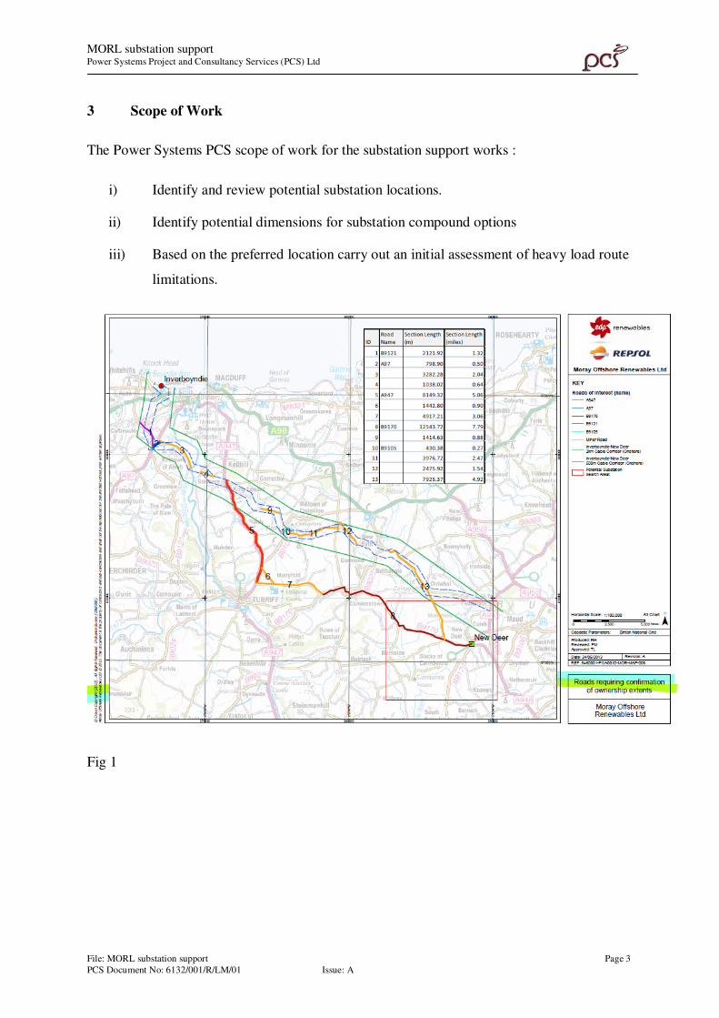
3 Scope of Work
The Power Systems PCS scope of work for the substation support works :
i) Identify and review potential substation locations.
ii) Identify potential dimensions for substation compound options
iii) Based on the preferred location carry out an initial assessment of heavy load route
limitations.
Fig 1
MORL substation support Power Systems Project and Consultancy Services (PCS) Ltd
File: MORL substation support Page 4
PCS Document No: 6132/001/R/LM/01 Issue: A
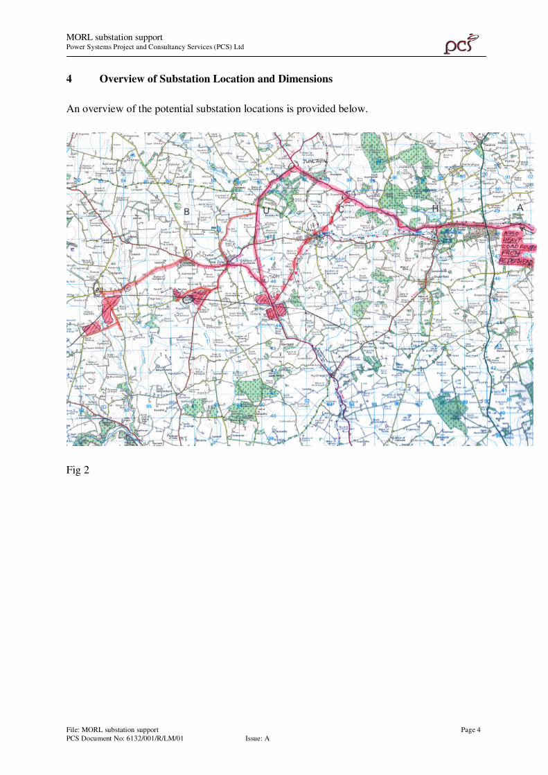
4 Overview of Substation Location and Dimensions
An overview of the potential substation locations is provided below.
Fig 2
MORL substation support Power Systems Project and Consultancy Services (PCS) Ltd
File: MORL substation support Page 5
PCS Document No: 6132/001/R/LM/01 Issue: A
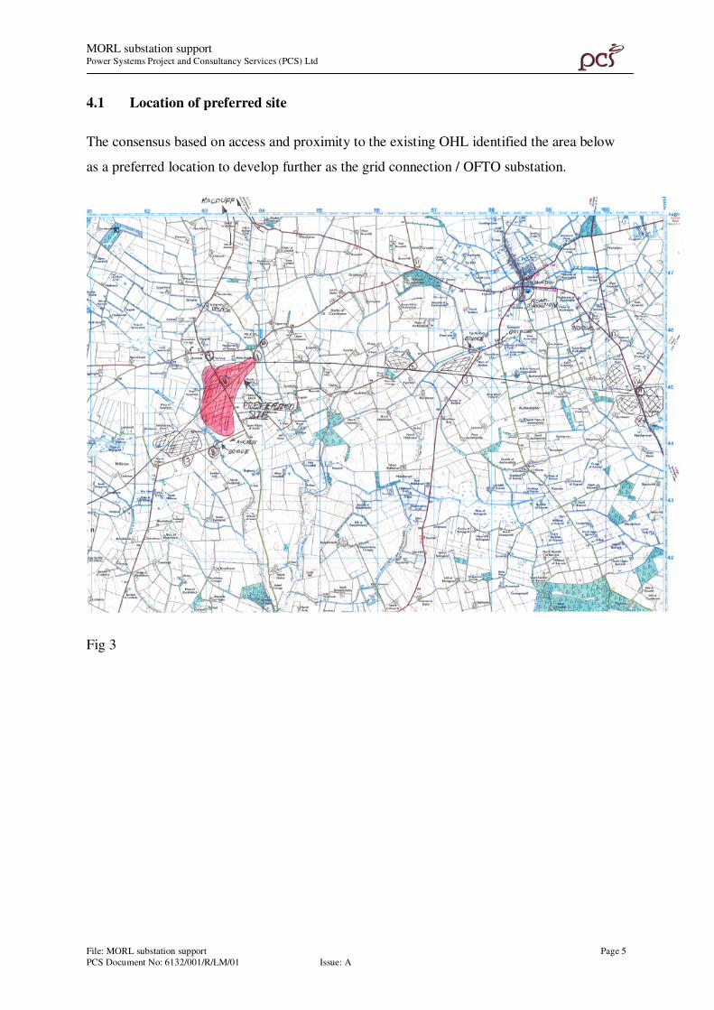
4.1 Location of preferred site
The consensus based on access and proximity to the existing OHL identified the area below
as a preferred location to develop further as the grid connection / OFTO substation.
Fig 3
MORL substation support Power Systems Project and Consultancy Services (PCS) Ltd
File: MORL substation support Page 6
PCS Document No: 6132/001/R/LM/01 Issue: A
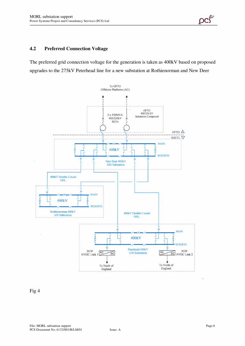
4.2 Preferred Connection Voltage
The preferred grid connection voltage for the generation is taken as 400kV based on proposed
upgrades to the 275kV Peterhead line for a new substation at Rothienorman and New Deer
.
Fig 4
MORL substation support Power Systems Project and Consultancy Services (PCS) Ltd
File: MORL substation support Page 7
PCS Document No: 6132/001/R/LM/01 Issue: A
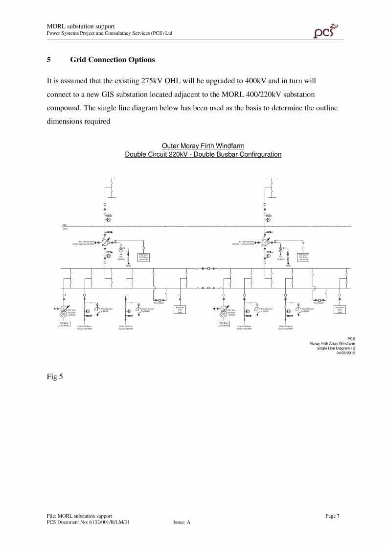
5 Grid Connection Options
It is assumed that the existing 275kV OHL will be upgraded to 400kV and in turn will
connect to a new GIS substation located adjacent to the MORL 400/220kV substation
compound. The single line diagram below has been used as the basis to determine the outline
dimensions required
Alternative
SVC Bank
< 60 MVAR
SVC Bank
> 60 MVAR
Harmonic
Filter
Bank
220kV Windfarm
Circuit 1 250 MVA
220kV Windfarm
Circuit 2 250 MVA
Shunt Reactor
xx MVAR
Shunt Reactor
xx MVAR
Bus Coupler
Aux
Supplies
SGT 400/220/33kV
500MVA (Tertiary 60 MVA)
SGT SVC
220/33kV
> 60MVA
Alternative
SVC Bank
< 60 MVAR
SVC Bank
> 60 MVAR
Harmonic
Filter
Bank
220kV Windfarm
Circuit 1 250 MVA
220kV Windfarm
Circuit 2 250 MVA
Shunt Reactor
xx MVAR
Shunt Reactor
xx MVAR
Bus Coupler
Aux
Supplies
SGT 400/220/33kV
500MVA (Tertiary 60 MVA)
SGT SVC
220/33kV
> 60MVA
NER NER
Outer Moray Firth Windfarm
Double Circuit 220kV - Double Busbar Confirguration
SSE
OFTO
PCS
Moray Firth Array Windfarm
Single Line Diagram / 2
04/06/2013
Fig 5
MORL substation support Power Systems Project and Consultancy Services (PCS) Ltd
File: MORL substation support Page 8
PCS Document No: 6132/001/R/LM/01 Issue: A
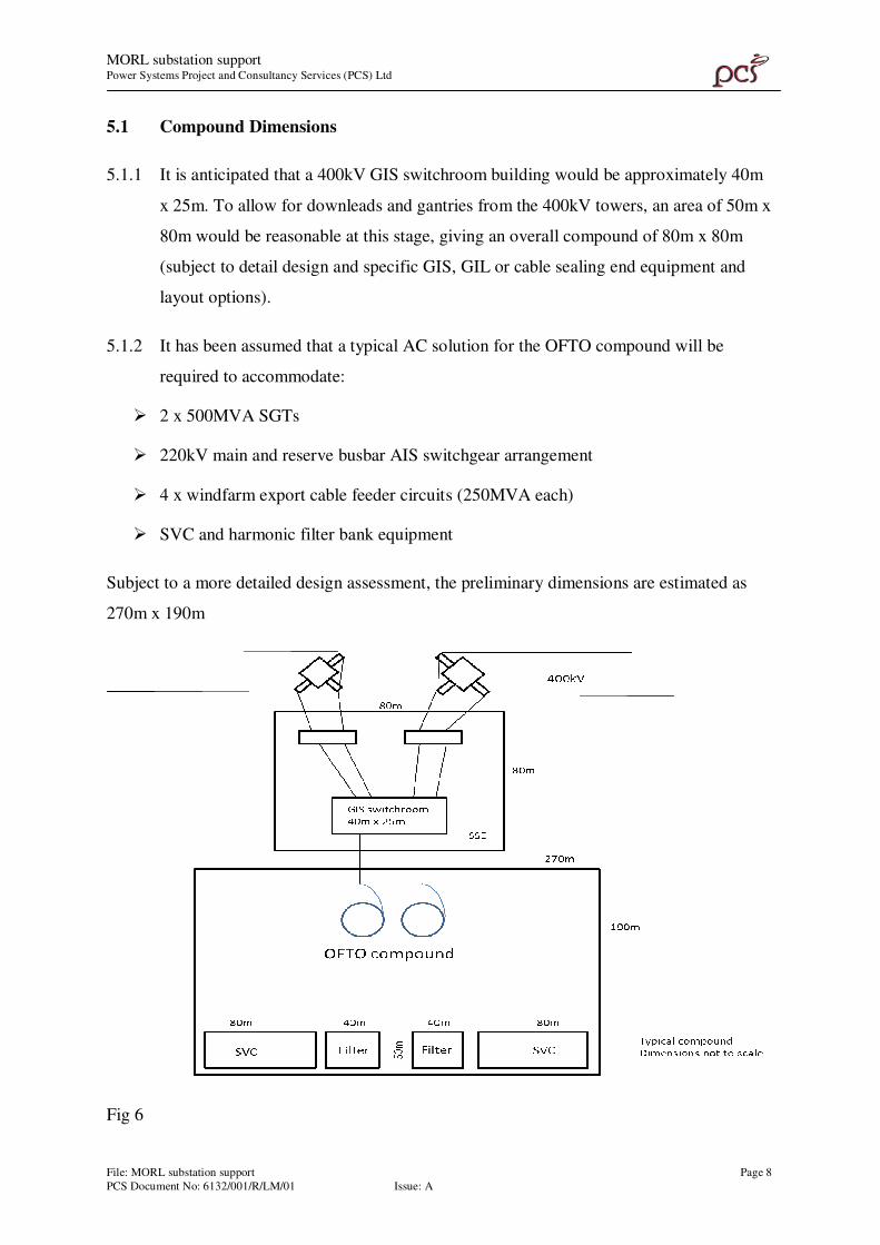
5.1 Compound Dimensions
5.1.1 It is anticipated that a 400kV GIS switchroom building would be approximately 40m
x 25m. To allow for downleads and gantries from the 400kV towers, an area of 50m x
80m would be reasonable at this stage, giving an overall compound of 80m x 80m
(subject to detail design and specific GIS, GIL or cable sealing end equipment and
layout options).
5.1.2 It has been assumed that a typical AC solution for the OFTO compound will be
required to accommodate:
� 2 x 500MVA SGTs
� 220kV main and reserve busbar AIS switchgear arrangement
� 4 x windfarm export cable feeder circuits (250MVA each)
� SVC and harmonic filter bank equipment
Subject to a more detailed design assessment, the preliminary dimensions are estimated as
270m x 190m
Fig 6
MORL substation support Power Systems Project and Consultancy Services (PCS) Ltd
File: MORL substation support Page 9
PCS Document No: 6132/001/R/LM/01 Issue: A
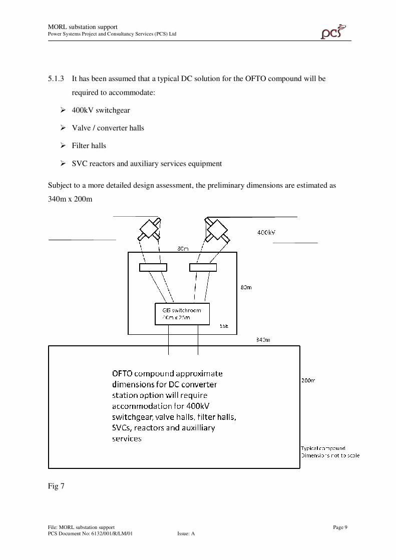
5.1.3 It has been assumed that a typical DC solution for the OFTO compound will be
required to accommodate:
� 400kV switchgear
� Valve / converter halls
� Filter halls
� SVC reactors and auxiliary services equipment
Subject to a more detailed design assessment, the preliminary dimensions are estimated as
340m x 200m
Fig 7
MORL substation support Power Systems Project and Consultancy Services (PCS) Ltd
File: MORL substation support Page 10
PCS Document No: 6132/001/R/LM/01 Issue: A
5.2 Road Access Observations
With reference to the Fig 2 on page 4, it is assumed at this stage that the A950 will be the
heavy load route from Peterhead. This road was driven along from Mintlaw to the proposed
site at Burnside with the options of the B910 via Maud and the A981 toward New Deer being
checked. No major concerns or restrictions were observed up and including New Deer.
The route from New Deer consists of the B9170 then onto the unclassified road heading
South West signposted for Greens. No immediate issues were identified in terms of junctions
or major restrictions till the area close to the proposed site near Burnside where there is a
narrow bridge over the Littler Water Burn, and a tight left hand turn onto the South
signposted for Fyvie. This junction also has over sailing 11kV wood pole conductors which
could restrict height.
6 Conclusions and Recommendations
The conclusions and recommendations from the grid connection assessments for the
proposed substation site are :
6.1 Conclusions
The area close to Burnside and existing angle tower on the 275kV Peterhead to Kintore /
Keith OHL would be the preferred location to develop for the MORL substation location.
6.2 Recommendations
It is recommended that a detailed heavy load transport study is undertaken to confirm swept
path requirements for the supergrid transformer deliveries together with structural assessment
of the small bridge on the potential delivery route.

MORL substation support Power Systems Project and Consultancy Services (PCS) Ltd
File: MORL substation support Page 11
PCS Document No: 6132/001/R/LM/01 Issue: A
6 Reference photographs
1. Preferred site area looking NE toward angle tower
2. Tight junction with wood pole OHL at Burnside
3. Narrow Bridge on unclassified road looking SW to angle tower
Fig 8
3
1
2

MO
RL
su
bst
atio
n s
up
port
P
ow
er S
yst
em
s P
roje
ct a
nd C
on
sult
an
cy S
erv
ices
(PC
S)
Ltd
Fil
e: M
OR
L s
ub
stati
on
su
pport
Pag
e 1
PC
S D
ocu
men
t N
o:
61
32
/00
1/R
/LM
/01
Is
sue:
A
Pre
ferr
ed s
ite
are
a l
oo
kin
g N
E t
ow
ard
an
gle
tow
er

MO
RL
su
bst
atio
n s
up
port
P
ow
er S
yst
em
s P
roje
ct a
nd C
on
sult
an
cy S
erv
ices
(PC
S)
Ltd
Fil
e: M
OR
L s
ub
stati
on
su
pport
Pag
e 2
PC
S D
ocu
men
t N
o:
61
32
/00
1/R
/LM
/01
Is
sue:
A
Tig
ht
jun
ctio
n w
ith
wood
pole
OH
L a
t B
urn
sid
e

MO
RL
su
bst
atio
n s
up
port
P
ow
er S
yst
em
s P
roje
ct a
nd C
on
sult
an
cy S
erv
ices
(PC
S)
Ltd
Fil
e: M
OR
L s
ub
stati
on
su
pport
Pag
e 3
PC
S D
ocu
men
t N
o:
61
32
/00
1/R
/LM
/01
Is
sue:
A
Narr
ow
Bri
dg
e on
un
class
ifie
d r
oa
d l
oo
kin
g S
W t
o a
ngle
tow
er