


Languages
Pages
Legal


ZBrush To Softimage XSI 16-Bit Displacement Guide
Greg Punchatz
Senior Creative Director, Janimation
November 10, 2005
© 2005 Pixologic, Inc. All rights reserved.
Pixologic and the Pixologic logo, and ZBrush and the ZBrush logo, are registered trademarks of Pixologic, Inc.
Photoshop is a registered trademark of Adobe Systems, Inc.
Softimage and Softimage XSI are registered trademarks of Softimage, Inc.
All other trademarks are the property of their respective owners.
Please mail comments or suggestions about this document to [email protected].

2
1. INTRODUCTION 3
2. MODEL SETUP IN XSI 3
3. WORKING IN ZBRUSH 3
3.1. OPENING THE MODEL IN ZBRUSH 3 3.2. CHECKING THE MODEL 4 3.2.1. FIXING OVERLAP PROBLEMS IN MODELS YOU’VE ALREADY MODIFIED 6 3.3. DETAILING THE MODEL 7 3.4. CREATING A DISPLACEMENT MAP 7 3.4.1. MORE ABOUT DISPLACEMENT OPTIONS 9
4. BACK INTO XSI 10
4.1. IMPORTING THE OBJ AND DISPLACEMENT MAP 10 4.1.1. SETTING UP THE DISPLACEMENT MAP OPTIONS 10 4.1.2. CHECKING THE DISPLACEMENT GEOMETRY 12
5. WORKING WITH MULTIPLE MODELS 14
5.1. USING XSI TO SET UP THE UVS FOR MODEL MERGING 14 5.2. DETAILING THE MERGED MODEL IN ZBRUSH 18 5.2.1. SETTING UP ZBRUSH GROUPS TO EASE YOUR WORK 18 5.2.2. EXPORTING 16-BIT DISPLACEMENT MAPS 19 5.2.3. EXPORTING 32-BIT DISPLACEMENT MAPS FROM MULTI DISPLACEMENT 2 20
6. ALL DONE! 21

1. Introduction This guide covers transferring models and displacement maps between Softimage XSI® and ZBrush. It will cover most of the dos and don’ts in both programs, but you will need a basic knowledge of both packages to understand some of the concepts.
These workflows makes use of a freely available ZBrush plugin called the Alpha Displacement Exporter, available for download at www.zbrushcentral.com. Please make sure you have it installed before going further.
2. Model Setup in XSI We’ll need to start with a model in XSI with a single set of UVs and then export it as an OBJ file, as ZBrush can only read one set of UVs. We need to make sure the model has certain properties for everything to work correctly:
• The model must have just a single set of UV coordinates, as ZBrush works with only one set of UVs at a time.
• The model cannot have any overlapping UVs. Overlapping UVs will (of course) cause undesired visual artifacts, and may also cause ZBrush to have difficulties as it creates a displacement map. Tip: There is an option in XSI’s UV editor that will show you polygon overlaps highlighted in pink.
• The mesh should consist of only quads and tris. In addition, there should be as few tris as possible, and they should be in the less visible areas of the model. Tip: You can use the Select n sided polygon tool in the MCP>select>n-sided polygons of XSI to find out if your mesh is has any five sided polygons.
3. Working in ZBrush
3.1. Opening the Model in ZBrush Now we need to import the model’s OBJ file into ZBrush. In ZBrush, models are called tools. This is different from traditional 3-D packages. So, to get your model into ZBrush you need to use the Tool:Import button under Tool menu at the top of your ZBrush interface, as shown in the figures below.

4
Fig. 1. THE TOOL PALETTE
Fig. 2. THE TOOL:IMPORT BUTTON
Tool:Import will bring up a standard dialog allowing you to select and open the model.
And we should mention this right now, too:
To save your model you must save it as a tool. This is done with the Tool:Save As button. Saving a document (Document:Save or Document:Save As) will not save a model.
3.2. Checking the Model After we import our model/tool, in this case a chimp I'm working on, there are several things we should do before we begin modeling.
First off, ZBrush provides a UV check tool that will show in red areas where problems are that we need to eliminate before we continue. Even after checking for this in XSI, I will still find from time to time I have missed the few very small overlapping UV's. Press Tool:Texture:Uv Check (the Uv Check button in the Texture subpalette of the Tool palette) to perform the UV check.

5
Fig. 3. THE UV CHECK BUTTON
Overlapping UVs show up in red. (Remember to rotate your model to check all of it). In this case I've missed a spot on the chimp’s forehead and also a few inside the mouth.
Fig. 4. OVERLAPPING UVS SHOWN BY UV CHECK
If you do find a problem, you need to return to XSI to fix it. As you can see in XSI, I missed these polygon overlaps.

6
Fig. 5. OVERLAPS IN THE ORIGINAL XSI LAYOUT
Fix the problems and bring the model back into ZBrush.
3.2.1. Fixing Overlap Problems in Models You’ve Already Modified If you don’t become aware of an overlap problem until you detail the model in ZBrush, you can still fix the overlaps easily. Here’s what to do:
1. Make sure your ZBrush model is at its lowest subdivision level. 2. Export the tool to its OBJ file, and then open that file from Softimage. 3. Fix the problems, and then save that file again from Softimage. 4. Import the file into ZBrush again, making sure that the corresponding tool is
selected and still at its lowest subdivision setting. This works because importing your OBJ file, while you still have your tool selected and at its lowest subdivision level, simply updates the UVs of the tool. This changes the UVs and any modifications to the lowest resolution of model you made while in XSI, yet it keeps all the detail work on the higher subdivision levels that were created in ZBrush. In fact, I’ve often completely redone my UV layout after detailing in ZBrush, using this technique. Of course, never change the polygon topology while editing in XSI. In other words, don’t add or remove any points, polygons or edges; moving points around is fine.
When moving a model to XSI and back, vertices are occasionally put in a different order. The problem won’t show itself until you raise the subdivision level on your ZBrush tool. If the polygons were reordered, you will know immediately as you will have a giant mess on your screen1. If this happens, and you must still fix your UVs outside of ZBrush, try exporting a dotXSI file from Softimage and using a program like Deep Exploration® to convert your dotXSI to OBJ.
1 This does not appear to occur when using ZBrush with XSI 5.

7
3.3. Detailing the Model Now that we have cleaned up our UVs, it’s time to detail the model. ZBrush has a million and one tools for detailing and sculpting your model and I can’t possibly cover that in this tutorial. But, I do recommend purchasing some DVD training material to get you up to speed quickly. Gnomon and Digital Tutors both have very good DVDs on learning ZBrush. Below is the chimp model after detailing in ZBrush.
Fig. 6. CHIMP MODEL WITH DETAILS DONE IN ZBRUSH
3.4. Creating a Displacement Map When your model is detailed, it’s time to create a displacement map and export it and the model to XSI. Here’s how to do it:
1. If your system resources permit, subdivide your model an additional level (or more) beyond the highest level you used for detailing. This can improve the final result. I subdivide as many times as my system allows.
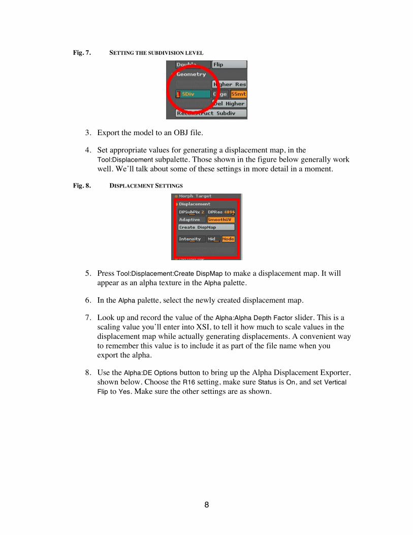
2. Now, set the model’s subdivision level (using the Tool:Geometry:SDiv slider) to display that model’s target geometry, i.e. the geometry the displacement map will be applied to. This is usually level 1. See figure Fig. 7`.
8
Fig. 7. SETTING THE SUBDIVISION LEVEL
3. Export the model to an OBJ file.
4. Set appropriate values for generating a displacement map, in the Tool:Displacement subpalette. Those shown in the figure below generally work well. We’ll talk about some of these settings in more detail in a moment.
Fig. 8. DISPLACEMENT SETTINGS
5. Press Tool:Displacement:Create DispMap to make a displacement map. It will appear as an alpha texture in the Alpha palette.
6. In the Alpha palette, select the newly created displacement map.
7. Look up and record the value of the Alpha:Alpha Depth Factor slider. This is a scaling value you’ll enter into XSI, to tell it how much to scale values in the displacement map while actually generating displacements. A convenient way to remember this value is to include it as part of the file name when you export the alpha.
8. Use the Alpha:DE Options button to bring up the Alpha Displacement Exporter, shown below. Choose the R16 setting, make sure Status is On, and set Vertical Flip to Yes. Make sure the other settings are as shown.

9
Fig. 9. ALPHA DISPLACEMENT EXPORTER
9. Click the Export Current button and save as a .TIF file. Remember, the file name is a good place to record your Alpha Depth Factor.
3.4.1. More About Displacement Options I tend to use the same settings for everything (as was shown in Fig. 8), but you can try other things. Here are brief descriptions of some of the displacement map options you might want to alter or play with:
• DPRes: Controls how big your displacement map will be! • DSubPix: Causes ZBrush to do additional levels of subdivision while creating
displacement maps. Setting it higher will give better results, but cause map generation to take more time.
In theory, subdividing your most detailed model an additional two times and setting DSubPix to 0 should have the same effect as not subdividing the final model further, but setting DSubPix to 2. However, you may find that one way is better for conserving memory, while another is better for generating the map quickly. The instructions I’ve given work well for me.
• Adaptive: Disables DSubPix and lets ZBrush decide how many times to subdivide regions of different detail when generating a displacement map. I find however that it’s more reliable and stable if you just go with the DSubPix setting of 2; it is a little slower than adaptive but seems to be more bulletproof.
• SmoothUV: I always have this set to On, as this option seems to help alleviate UV displacement seams in XSI.
• Mode: This needs to be On when creating displacement maps. If it’s Off, you’ll get a bump map. I will sometimes create bump maps from higher subdivision levels (rendered from sublevels of 3, 4 or 5 if there are a total of 6 or 7 subdivisions) and then the Mode button will be Off.

10
4. Back Into XSI Now it’s time to bring the displacement map back into XSI and apply it.
4.1. Importing the OBJ and Displacement Map In XSI 5.0 importing ZBrush models and displacement maps is easier than ever with the new displacement options in the OBJ importer. (For reasons of space we’ll have to omit the procedure in the previous versions of XSI, but the ideas are the same). In XSI click File>Import>Obj File... and select the OBJ file that you exported from ZBrush.
Fig. 10. XSI IMPORT DIALOG
4.1.1. Setting Up the Displacement Map Options After selecting the OBJ file and before you click OK, go to the Displacement Options tab on the OBJ importer Property Page (below). Select the TIFF file that you exported from ZBrush as the Image. Enter the Alpha Depth Factor next. This was information I said to write down or include in your file name when you exported your TIFF from ZBrush. Notice how, in the figure below, I included the alpha depth factor in the filename. Now you know why!

11
Fig. 11. ALPHA DEPTH FACTOR ENTRY
When XSI 5.0 creates a render tree for you, it will use this number to set a change range node in the displacement shader that it will create for you. If you don't have XSI 5.0 you will need to create your render tree manually so it looks something like that shown in the figure below.
Fig. 12. INCORPORATING THE DISPLACEMENT FACTOR INTO THE RENDER TREE
The Softimage_sib_interp_linear node that XSI 5.0 creates in the render tree is really just a change range node. It simply shifts the Alpha Depth Factor number so that instead of the depth factor being given in a range from 0 to that number, it is given as a range from a negative number to a positive number.
For example, the Alpha Depth Factor for my chimp was 2.609. Half of that is 1.304, so my new range start was -1.304 and my new range end is 1.304. The total range is the same, it’s just been adjusted so that the midpoint of the range is 0.
You also use the 1.304 setting in the geometric approximation tab (located under Properties on the far left) for your mesh; set it as the value for the maximum displacement setting. This setting tells Mental Ray the maximum by which it is allowed to displace any polygon. If you are using XSI 5.0 you do not need to set this up manually as it’s done automatically for you.

12
The other option in the XSI 5.0 Object Importer Property Page that you need to turn on is the View Dependent Refinement. This automatically sets your geometric approximation displacement settings to be view dependent. If you forgot to flip your image vertically when you exported from ZBrush you can also use the Flip Image Vertically option in the displacement options tab.
Now press OK and to finish importing the OBJ file.
4.1.2. Checking the Displacement Geometry It’d be nice if everything just worked, but as we all know, things are never that simple in a production pipeline. Once you have your model imported from your OBJ file and your render tree set up, you will need to check your geometric approximation. First thing to do before tweaking any settings is to draw a render region by pressing ‘q’ and dragging out a window.
4.1.2.1. Tweaking the Displacement Map If at this point you look at the render region and want to make some simple tweaks to the displacement map, you can just open it up in Photoshop and do what you need. On the other hand, if you want to do more complex things, you can go back to the displacement map in ZBrush and if you want, and use the ZAppLink plugin (available for free download at www.ZBrushCentral.com) to use Photoshop directly from ZBrush!
4.1.2.2. More Tweaks The polygons on the nose of this chimp could have been laid out a little better, and, as a result, I have some triangulation being caused by the displacement map and the detail of the model is not adequate. So we’re going to solve both problems by adjusting our displacement settings or polygon mesh subdivision settings.
Fig. 13. TRIANGULATION ARTIFACTS
The thing to keep in mind is that if you have a higher subdivision level on your polygon mesh you can use lower displacement settings since you initially have more polygons to start with. If I can get the detail I want without any artifacts, I prefer to keep the model at a subdivision 1 level for rendering. In the case of the chimp, I needed to go to a level 2 subdivision to eliminate displacement artifacts.
I want to add a couple of notes on the fine displacement settings; the box that says Refinement Settings.
13
First off, the length setting subdivides the surface or curve so that no edge length of the tessellated triangle exceeds this value. Which basically means the lower the setting, the greater the detail and slower the render.
View Dependent allows Mental Ray to adjust the number of polygons depending on how close to the screen your object is. This is a very important setting, and I almost always have that On.
The subdivision limit—or cursive steps area of the Property Page—controls how much Mental Ray will subdivide on any given polygon. Again, higher numbers equal more detail and longer render times. Optimizing Mental Ray for displacements is an art in itself and I suggest you read up on BSP optimization.
You should compare renders from ZBrush to see if you’re getting an accurate displacement. Sometimes you have to mess with the numbers in the change range slightly to get exactly what you want.
Another way of analyzing whether you’ve done an accurate displacement job is to export an OBJ of one in your higher-level subdivisions from ZBrush and import it into XSI for a side-by-side comparison.
I would not suggest importing your highest-level subdivision into any version besides XSI 5.0 for two reasons. First, the OBJ importer from XSI used to be slow and when you tried to import a model with millions of polygons it would take forever. And the second reasons is that sometimes it would just crash.
In 5.0 all of this is changed because the new Object Importer is blazingly fast. Plus, XSI now has what Softimage calls a gigapolygon core! What does this mean? It means XSI will now handle huge polygons sets and will be able to render them.

14
Fig. 14. RENDERED IMAGE
5. Working with Multiple Models ZBrush allows you to work with displacement maps for multiple models by using the Multi Displacement 2 plugin. It is part of the Alpha Displacement Exporter plug-in (mentioned earlier), that you can find at www.zbrushcentral.com. To use this plug-in you must set your models up in XSI in a very specific way.
We’re going to work with the mouth of the chimp, which includes his gums, upper teeth, and bottom teeth. This requires merging all of these models together in XSI, but before doing so, we need to lay out the UVs in a way Multi Displacement 2 in ZBrush will understand.
5.1. Using XSI to Set Up the UVs for Model Merging Multi Displacement 2 looks for UVs in quadrants in the UV map, outside of the 0 to 1 UV coordinate range. So, we need to lay our UVs as usual to start with, and then use the texture editor to put each set of UVs in its own unique space. For example, below are the upper teeth UVs, with UVs laid out in the 0 to 1 coordinate range.

15
Fig. 15. INITIAL UV MAP FOR TOOTH UVS
What we are going to do is select all of the UV's and move them one unit to the right. Do it like this:
• Make sure the Set button is Off. • Select all of our UV’s, and type 1+ in the U coordinate box. This will move
the UV's exactly 1 unit to the right. The image below shows the UV’s before the 1+ change has taken place.

16
Fig. 16. UV MAP BEFORE THE ‘1+’ CHANGE
We will do the same with the bottom teeth, except this time we'll move them 2 units to the right:
Fig. 17. BOTTOM TEETH
In XSI 5.0 we now have the ability to see multiple objects’ UVs at the same time. So, now we’re going to select our gums, upper teeth, and lower teeth so we can see that the UVs are laid out correctly. As you can see, our objects’ UVs are laid out with each in its own unique UV space. You will need to make sure that wrapping is turned on for U and V in your texture projection Property Page for each object. This will allow you to keep

17
your UVs offset from the normal UV space while texturing and rendering if you don’t want to move the UVs back to normal UV space later.
Fig. 18. MULTIPLE OBJECT UVS IN SAME VIEW
We now need to merge our model in XSI. We will do this using Model>Create>Polygon Mesh>Merge tool. In the Merge Property page, turn the tolerance down to zero and click the Specify Properties: Edit Transfer button. This will bring up a transfer page in the drop-down menu. Pick UV Space then click the In Prop button on the left-hand side so you select all the UVs. Now, press the Transfer/Merge button and your UVs are transferred. Freeze the new mesh and rename it something appropriate. Now the model is ready to export to ZBrush.

18
Fig. 19. MERGE SETTINGS
5.2. Detailing the Merged Model in ZBrush In ZBrush go to Tool:Import and bring the OBJ file that you exported from XSI. Now you’re ready for detailing.
5.2.1. Setting Up ZBrush Groups to Ease Your Work You can make it easier to work with the model in ZBrush by coloring (or even hiding) the different UV quadrants as if they were separate models. In ZBrush, press the Tool:Polygroups:UV Groups. (That is, the UV Groups button in the Polygroups submenu of the Tool menu.) This defines groups in the model for each quadrant in the UV space. If you then turn On the Frame button in the top left-hand corner of the ZBrush interface, you will see different colors displayed for each group.

19
Fig. 20. GROUP COLORS WITH ‘FRAME’ BUTTON ON.
Sometimes ZBrush randomly picks similar colors for more than one group, which can make it difficult to correctly identify your UV quadrants. To remedy this, while holding down Ctrl and Shift click on one of your objects which is part of a group colored similarly to another group. This will hide all the other groups and you can then press the Tool:Polygroups:Group Visible to (randomly) change the color of the visible group to something else. Hold down Shift-Ctrl and click anywhere on the empty part of the canvas to make everything visible again.
Then, of course, you do the fun stuff and detail the model in ZBrush.
5.2.2. Exporting 16-Bit Displacement Maps Remember, the whole point of this section was to generate displacement maps for multiple XSI models in one go, even though ZBrush works with a single model at a time. The instructions above showed you how to merge the XSI models and bring them into ZBrush. Now comes the reward for all this work, using a special ZBrush plugin to create all of the individual displacement maps at once.
Press Zplugin:Multi Displacement 2:Export Options (this is actually part of the Alpha Displacement Exporter plugin) to bring up the export options dialog. Press D16 and turn it On (yellow). This will generate a 16-bit grayscale image. Similarly, set the other marked controls as shown, which will flip the displacement maps, automatically smooth the UVs, and a few other things we won’t go into details on. (For some settings, you click on the control repeatedly until the values cycle through to the one you want.)

20
Fig. 21. MULTI DISPLACEMENT 2 FILE FORMAT EXPORT SETTINGS
Now we’re ready to render our displacement maps. First off, remember to be in your model’s lowest subdivision level (set with the Tool:Geometry:SDiv slider) then set the options in Multi Displacement 2 to be like this:
Fig. 22. MULTI DISPLACEMENT 2 MAP GENERATION OPTIONS
Generate our new maps by pressing the Create All button. This will prompt you for a name for your files, and ZBrush will automatically create differently numbered versions of this file name. (Details of the naming conventions are in the documentation that comes along with the Alpha Displacement Exporter.) Once this is complete, you can attach the displacement maps, as I did before, on the single model.
5.2.3. Exporting 32-Bit Displacement Maps from Multi Displacement 2 You can also export 32-bit displacement maps with your models object space baked into it. This removes the need to record the alpha depth factor for each model or each map. For rendering with 32-bit maps in Mental Ray, you’ll just use an alpha depth factor of 2.2 for all your displacement maps. This number is consistent regardless of your model or your maps. You must generate the map from within Multi Displacement 2 to have the alpha depth factor baked in.

21
To do this, simply follow the steps in the previous section, except start by selecting the D32 rather than the D16 configuration (and of course, leave Bits at 32 Bits).
One issue to note is that you will be unable to modify a 32-bit RGB image using standard paint tools if there are any artifacts. If you are getting artifacts and want to fix them using Photoshop or something similar, it is recommended that you export a 16-bit map.
6. All Done! This completes my first guide for working with ZBrush in XSI. I'm planning on doing another one in the very near future that covers on how to use ZBrush to enhance morph targets in XSI. I hope you found this guide informative and it helps you using ZBrush and XSI together more effectively.
Top Related