


Languages
Pages
Legal

YAMAHASY85 Music Synthesizer
Owner’s Manual 2- Feature Reference -

GENERAL EDITING PROCEDURE
PATTERN EDIT MODE
SONG EDIT MODE
DRUM VOICE EDIT MODE
VOICE EDIT MODE
PERFORMANCE EDIT MODE
UTILITY MODE
WAVE EDIT MODE
APPENDIX
2
CONTENTS
GENERAL EDITING PROCEDURE
Mode Selection ............................................. 8 Selecting Specific Edit Functions ............... 8 Selecting & Editing Parameters................10 Controller Assignment Display ..................11
Performance Edit Mode
Edit1: Layer
1: Voice Number .................................142: Volume .............................................153: Pan ...................................................164: Tune .................................................175: Note Limit ........................................186: Velocity Limit ...................................207: CS Enable .......................................22Layer Data Copy .................................23
2: Performance Total Level .....................243: Performance Name ..............................254: Layer Voice Edit
1: Oscillator ..........................................262: Amplitude EG ..................................263: Filter .................................................264: Pitch EG ..........................................265: LFO ..................................................266: Controller .........................................267: Voice Total Level ...........................268: Voice Name.....................................26
Quick Edit1: Amplitude EG Offset ............................272: LFO & Filter Offset ..............................293: Controller Conditions ...........................314: Other Conditions ..................................335: Effect Type ............................................356: Effect Parameter ..................................36
Effect Edit1: Mode, Type ...........................................372: Send Select & Level ............................38
3: Layer Dry Output Select .....................404: Output Level .........................................415: Wet : Dry Balance ...............................426: Send & Effect 2 Mix Level .................437: Effect 1 Parameters .............................448: Effect 2 Parameters .............................449: Control Parameters ..............................4510: Control LFO ........................................47Effect Data Copy.......................................48Effect Signal Flow Display .......................49
Job1: Layer Controller Sync ..........................502: Layer Exchange ....................................513: Performance Edit Recall .....................524: Performance Initialize ..........................53
Performance Compare ...............................54
Performance Store .....................................55
Voice Edit Mode
Edit1: Oscillator ................................................582: Amplitude EG
1: AEG Level & Rate .........................602: Level Scaling ..................................623: Sensitivity ........................................63AEG Data Copy...................................64
3: Filter1: Type, Cutoff Frequency .................652: Cutoff Scaling .................................693: FEG Level & Rate ..........................704: Filter Sensitivity ..............................72Filter Data Copy ..................................73
4: Pitch EG1: Level & Rate ...................................742: Range, Sensitivity ...........................76Pitch EG Data Copy ...........................77
5: LFO1: LFO ..................................................78

3
2: LFO Speed Sensitivity ...................80LFO Data Copy ...................................81
6: Controller1: Pitch Bend Range ..........................822: Modulation Wheel Depth ...............833: Foot Controller Depth ....................854: After Touch Depth ..........................875: CS3 Parameter Edit .......................896: CS4 Parameter Edit .......................91Controller Data Copy ..........................937: Voice Total Level ...........................948: Voice Name.....................................95
Quick Edit1: Wave ......................................................962: Amplitude EG........................................983: Filter .................................................... 1004: LFO ..................................................... 1025: Effect Type ......................................... 1036: Effect Parameter ............................... 104
Effect Edit1: Mode, Type ........................................ 1052: Send, Mix, Wet : Dry........................ 1063: Output Level ...................................... 1084: Effect 1 Parameters .......................... 1095: Effect 2 Parameters .......................... 1096: Control Parameters ........................... 1107: Effect LFO .......................................... 112Effect Data Copy.................................... 113Effect Signal Flow Display .................... 114
Job1: Voice Edit Recall ............................... 1152: Voice Initialize ................................... 116
Voice Compare ........................................ 117
Voice Store ............................................... 118
Drum Voice Edit Mode
Edit1: Key Parameters 1 ............................. 1202: Key Parameters 2 ............................. 1223: Total Level ......................................... 1234: Drum Voice Name ............................. 124Drum Key Data Copy ............................ 125
Quick Edit1: Effect Type ......................................... 1262: Effect Send Level .............................. 127
Effect Edit1: Mode, Type ........................................ 1282: Key Send Select & Level ................. 1293: Key Dry Output Select ..................... 1314: Output Level ...................................... 1325: Wet : Dry Balance ............................ 1336: Send & Effect 2 Mix Level .............. 1347: Effect 1 Parameter2 .......................... 1358: Effect 2 Parameter2 .......................... 1359: Control Parameters ........................... 13610: Control LFO ..................................... 138Effect Data Copy.................................... 139Effect Signal Flow Display .................... 140
Job1: Key Data Initialize ............................. 1412: Key Data Exchange .......................... 1423: Drum Voice Edit Recall .................... 1434: Drum Voice Initialize ......................... 144
Drum Voice Compare ............................. 145
Drum Voice Store .................................... 146

4
Song Edit Mode
Multi Edit1: Voice Select ....................................... 1482: Volume ................................................ 1493: Pan ...................................................... 1504: Effect Send Level .............................. 1515: Note Shift ........................................... 1526: Tune .................................................... 1537: Effect Type, Out Balance ................. 1548: Song Name ........................................ 1559: Song Initialize .................................... 156
Track Edit ................................................. 157
Effect Edit1: Mode, Type ........................................ 1662: Send Select & Level ......................... 1673: Inst Dry Output Select ...................... 1694: Output Level ...................................... 1705: Wet : Dry Balance ............................ 1716: Send & Effect 2 Mix Level .............. 1727: Effect 1 Parameters .......................... 1738: Effect 2 Parameters .......................... 1739: Control Parameters ........................... 17410: Control LFO ..................................... 176Effect Data Copy.................................... 177Effect Signal Flow Display .................... 178
Job1: Clear Song ......................................... 1792: Copy Song ......................................... 1803: Memory Status/Clear Rhythm Track
.................................................... 181,1824: Track Mixdown................................... 1835: Delete Track ...................................... 1856: Quantize ............................................. 1867: Copy Measure ................................... 1888: Delete Measure ................................. 1909: Insert Measure ................................... 19110: Erase Measure ................................ 19211: Remove Event ................................. 19312: Clock Move ...................................... 19513: Transpose......................................... 19614: Note Shift ......................................... 197
15: Velocity Modify ................................ 19816: Gate Time Modify ........................... 19917: Crescendo ........................................ 200
Pattern Edit Mode
Job1: Copy Pattern ...................................... 2022: Clear Pattern...................................... 2033: Instrument Change ............................ 2044: Velocity Modify .................................. 205
Pattern Name ........................................... 207
Utility Mode
Synth Setup1: System ................................................ 2102: MIDI 1 (Channel Parameters) ......... 2123: MIDI 2 (Other Parameters) .............. 2134: Program Change Table .................... 2155: Velocity ............................................... 216
SEQ Setup1: Click Condition ................................... 2172: Record Condition ............................... 2193: Accent Velocity .................................. 2204: Song Chain ........................................ 221
Bulk Dump1: all ......................................................... 2222: synth all .............................................. 2223: sequencer all ..................................... 2224: pattern all ........................................... 2225: 1 performance.................................... 2226: 1 voice ................................................ 2227: 1 song ................................................. 222

5
Card1: Card All Load/Save ........................... 2232: Card Format ....................................... 224
Disk1: Disk All Load/Save............................ 2252: Disk All Load/Save Synth ................ 2253: Disk All Load/Save Seq ................... 2254: Disk NSEQ Load/Save ..................... 2255: Disk Other Load/Save ...................... 2256: MDR .................................................... 2287: Rename/Delete .................................. 2318: Backup Disk ....................................... 2329: Disk Status ......................................... 23410: Disk Format ..................................... 235
Wave Edit Mode
Wave Number Select .............................. 239
Edit1: Waveform
1: Wave Assign ................................ 2402: Wave Name ................................. 240
2: Sample1: Sample Key Map ......................... 2432: Sample Data ................................ 243
Wave Initialize .......................................... 247
Sample Dump1: Sample Dump Recieve ..................... 2482: Sample Dump Transmit .................... 249
Wave Card Load ..................................... 250
Wave Disk Load/Save 1 Sample .......... 251
Wave Memory Status Display................ 252
APPENDIX
EFFECTS .................................................. 254Effect Signal Flow Diagrams — VoiceMode ........................................................ 256Effect Signal Flow Diagrams — Drum Voice,Performance, and Song Modes .................. 264The Effects & Their Parameters .......... 274
WAVE MEMORY EXPANSION .............. 285Memory Installation ................................ 286
INITIAL DATA & BLANK CHARTINITIAL PERFORMANCE “InitPerf” ..... 289INITIAL NORMAL VOICE “InitVce” ...... 290INITIAL DRUM VOICE “DR PTN” ........ 292INITIAL DRUM VOICE “DR Zones” ..... 294INITIAL DRUM VOICE “DR GMIDI” .... 296INITIAL DRUM VOICE “DR Efect” ...... 298INITIAL MULTI “InitSong” ..................... 300SYSTEM SETUP .................................... 301INTERNAL PERFORMANCE LIST (1) .... 302INTERNAL PERFORMANCE LIST (2) .... 304INTERNAL VOICE LIST (1) .................. 306INTERNAL VOICE LIST (2) .................. 307INTERNAL VOICE LIST (3) .................. 308INTERNAL VOICE LIST (4) .................. 309INTERNAL WAVE LIST......................... 310BLANK CHART — PERFORMANCE... 311BLANK CHART — VOICE .................... 312BLANK CHART — DRUM VOICE ....... 314BLANK CHART — MULTI .................... 316BLANK CHART — SYSTEM SETUP .. 317
About the Standard MIDI File Format .. 318
SPECIFICATIONS ................................... 319
ERROR MESSAGES ............................... 320
TROUBLE SHOOTING............................ 324
INDEX ....................................................... 326

GENERAL EDITINGPROCEDURE
Mode Selection ........................................... 8
Selecting Specific Edit Functions ............... 8
Selecting & Editing Parameters ............... 10
Controller Assignment Display ................. 11

8
The SY85 makes editing easy by providing a consistent, logical controlinterface via which parameters can be located and edited. Once you’ve learnedthe general procedure, you can locate and edit any of the SY85’s many param-eters quickly and easily.
Mode Selection
All SY85 edit modes are selected via the MODE matrix keys. To select theVOICE EDIT mode, for example, press the VOICE mode key so that its indica-tor lights, than press the second SUB MODE key in the VOICE column(EDIT).
Selecting Specific Edit Functions
Once you’ve selected an edit mode, one way to select the various editscreens and functions it contains is to use the PAGE [k] and [l] keys. The[k] and [l] keys step backward and forward through the available screens,respectively. Hold either of these keys for continuous stepping in the specifieddirection.
An alternative method is to use the [MENU] key. If you press the [MENU]key ion the VOICE EDIT mode, for example, you’ll see a display somethinglike this:
VOICE`EDIT`MENU``1ø8````````````````````
`````````````1:Oscillator```````````````
GENERAL EDITING PROCEDURE

9
From this display you can use either the data entry dial or the [-1] and [+1]keys to directly select any of the 8 available functions, then press the [ENTER/YES] key to actually select the specified function.
In some cases the PAGE [k] and [l] or [MENU] keys will take you toanother entry screen. If you select “3: Filter” after pressing the [MENU] key inthe VOICE EDIT mode, and then press [ENTER/YES], you’ll see the followingdisplay:
“Hit [ENTER]” will be flashing. In this case press [ENTER/YES] again toaccess the filter functions. Once in the filter “sub-mode” you can use the PAGE[k] and [l] or [MENU] keys to select the various filter functions, as de-scribed above. When you have finished with the filter functions, press [EXIT/NO] to return to the normal VOICE EDIT mode.
FILTER``````````````````````````````````
`````````````````````````````Hit`[ENTER]
GENERAL EDITING PROCEDURE

10
Selecting & Editing Parameters
Most SY85 edit screens contain several parameters that can be selected andedited. In most cases you can simply operate the continuous slider immediatelybelow the parameter you want to edit on the display. Operating a slider auto-matically moves the underline cursor to the corresponding parameter. In theexample below, for example (this is the VOICE EDIT mode Oscillator screen),the [CS5] slider can be used to adjust the “Fine” parameter.
The parameters can also be edited by first moving the cursor to the requiredparameter by pressing the corresponding function key ([F7], for example, wouldselect the “Rndm” parameter in the above display), and then by using either thedata entry dial or the [-1] and [+1] keys to adjust the parameter’s value.
In some special cases you’ll also use the function keys as parameter“switches,” and the [SHIFT] key is sometimes called into play to access sec-ondary functions. Such exceptions are described in the appropriate sections ofthe manual.
OSC``Wave``````Mode`Fine`Note`Rndm``Rvs`
P001`Piano`````norm```+0```+0````0``off`
GENERAL EDITING PROCEDURE

11
Controller Assignment Display
It is possible to assign a wide range of parameters to be controlled by the[CS1] through [CS4] sliders when playing in the VOICE or PERFORMANCEPLAY modes. Since it is easy to forget what parameters have been assigned towhich sliders, the SY85 features a controller assignment display that can beselected temporarily by pressing the [SHIFT] key in the VOICE or PERFORM-ANCE PLAY mode.
PERFORMANCE PLAY mode
VOICE PLAY mode
DRUM VOICE PLAY mode
This display shows the names of the parameters assigned to sliders [CS1]through [CS4] for the current voice or performance combination, so you cantake a quick peek to refresh your memory even while playing.
CS`````1(LFO):Ef1`Mix```````````````````
ASSGIN`2(MW`):Ef2»Hi`Gain```````````````
CS`````1(LFO):Ef1`Mix``````3:----------`
ASSGIN`2(MW`):Ef2»Hi`Gain``4:----------`
CS`````1(LFO):Ef1`Mix```````````````````
ASSGIN`2(MW`):Ef2»Hi`Gain```````````````
GENERAL EDITING PROCEDURE

PERFORMANCE EDIT MODE

14
1: VOICE NUMBER[PERFORMANCE] → [EDIT] → [MENU] → 1:Layer → [ENTER/YES] → [ENTER/YES] →
→ [MENU] → 1:Voice Number → [ENTER/YES]
SY85 performance combinations can have up to four voices assigned to different“layers” — A, B, C and D. This screen lets you assign voices to the layers.
PERFORMANCE EDIT MODE / 1:Layer
Voice Number A, B, C, DRange: off, A1 … H7 (internal & card)Controls: MEMORY, GROUP, PROGRAM, [CS2], [CS4], [CS6], [CS8],
[-1] [+1], Dial
After moving the cursor to the layer you want to edit by pressing the [F2],[F4], [F6] or [F8] function key, use the [INTERNAL 1], [INTERNAL 2], and[CARD] keys to select the memory area from which the voice is to be selected,and then use the GROUP and PROGRAM keys to select the voice. Voiceswithin the selected memory bank can also be selected directy for each layer bythe [CS2], [CS4], [CS6], and [CS8] keys. Internal and card voices cannot bemixed.
The voices can individually turned on or off by using the [-] (off) and [+](on) keys while holding the [SHIFT] key.
The name of the currently selected voice is shown in the upper right cornerof the display. The characters “ABCD” to the right of the voice name indicatethe status of each voice:
• Capital letter = voice on.• Lower-case letter = voice muted.• “-” = voice is off.
For example, “Ab-D” indicates that voices A and D are on, voice B ismuted, and voice C is off.
F1
CS1
F2
CS2
F3
CS3
F4
CS4
F5
CS5
F6
CS6
F7
CS7
F8
CS8
LAYER`Voice`Number````````<InitVce`>ABCD
````A=¡A1`````B=¡A1`````C=¡A1`````D=¡A1

15PERFORMANCE EDIT MODE / 1:Layer
2: VOLUME
For optimum balance between the voices in a performance combination, thisscreen allows the volume of each voice to be adjusted individually.
The name of the currently selected voice/layer is shown in the upper rightcorner of the display. The characters “ABCD” to the right of the voice nameindicate the status of each voice: a capital letter if the voice is on, a lower-caseletter if the voice is muted, and a dash if the voice is off.
VolumeRange: 0 … 127Controls: [CS2], [CS4], [CS6], [CS8], [-1] [+1], Dial
Use the [CS2], [CS4], [CS6], and [CS8] sliders to adjust the volume levelsof the A, B, C, and D layer voices, respectively. A setting of “0” produces nosound, while a setting of “127” produces maximum volume. The vertical bargraphs next to each parameter provide a visual indication of volume levels —the longer the bar the higher the volume. Voices that are turned off are indi-cated by “----” on the display.
[PERFORMANCE] → [EDIT] → [MENU] → 1:Layer → [ENTER/YES] → [ENTER/YES] →→ [MENU] → 2:Volume → [ENTER/YES]
F1
CS1
F2
CS2
F3
CS3
F4
CS4
F5
CS5
F6
CS6
F7
CS7
F8
CS8
LAYER`Volume``````````````<InitVce`>ABCD
``````127ƒ``````127ƒ``````127ƒ``````127ƒ

16
3: PAN[PERFORMANCE] → [EDIT] → [MENU] → 1:Layer → [ENTER/YES] → [ENTER/YES] →
→ [MENU] → 3:Pan → [ENTER/YES]
In multi-layer performance combinations, interesting stereo effects can be pro-duced by placing the output from different layers at different locations in the stereosound field. The parameters in this screen determine the position in the stereo soundfield in which the sound from each active layer will be heard (left to right).
PERFORMANCE EDIT MODE / 1:Layer
The name of the currently selected voice/layer is shown in the upper rightcorner of the display. The characters “ABCD” to the right of the voice nameindicate the status of each voice: a capital letter if the voice is on, a lower-caseletter if the voice is muted, and a dash if the voice is off.
PanRange: -31 … +31Controls: [CS2], [CS4], [CS6], [CS8], [-1] [+1], Dial
Use the [CS2], [CS4], [CS6], and [CS8] sliders to adjust the pan positionsof the A, B, C, and D layer voices, respectively. Minus values represent pan-ning to the left, and positive values represent panning to the right. “0” posi-tions the sound of the selected layer in the center of the stereo sound field.Voices that are turned off are indicated by “---” on the display. The upper lineof the display also shows a graphic representation of the stereo sound fieldwith “L” representing “left” and “R” representing “right.” As you change thepan value the vertical bar will appear at the corresponding position on thegraphic display.
F1
CS1
F2
CS2
F3
CS3
F4
CS4
F5
CS5
F6
CS6
F7
CS7
F8
CS8
LAYER`Pan`L¯¯Æ¯¯R`````````<InitVce`>ABCD
```````+0````````+0````````+0````````+0`

17PERFORMANCE EDIT MODE / 1:Layer
4: TUNE
More than just simple tuning, the note shift and fine tune parameters make itpossible to create harmony and voice-thickening detune effects between layers.
[PERFORMANCE] → [EDIT] → [MENU] → 1:Layer → [ENTER/YES] → [ENTER/YES] →→ [MENU] → 4:Tune → [ENTER/YES]
The name of the currently selected voice/layer is shown in the upper rightcorner of the display. The characters “ABCD” to the right of the voice nameindicate the status of each voice: a capital letter if the voice is on, a lower-caseletter if the voice is muted, and a dash if the voice is off.
NtShft (Note shift)Range: -63 … +63Controls: [CS1], [CS3], [CS5], [CS7], [-1] [+1], Dial
Individually shifts the pitch of each active element up or down in semitonesteps.
Use the [CS1], [CS3], [CS5], and [CS7] sliders to shift the pitch of the A,B, C, and D layer voices, respectively. A setting of “-12,” for example, shiftsthe pitch of the selected layer down by one octave; a setting of “+4” shifts thepitch up by a major third.
The Note Shift parameter can be used to transpose a voice to its mostuseful range, or to create harmony (intervals) between different layers in aperformance combination.
Voices that are turned off are indicated by “---” on the display.
Fine (Fine tuning)Range: -7 … +7Controls: [CS2], [CS4], [CS6], [CS8], [-1] [+1], Dial
Allows slight upward or downward pitch adjustment of each active element.Use the [CS2], [CS4], [CS6], and [CS8] sliders to fine tune the A, B, C,
and D layer voices, respectively.The maximum minus setting of “-7” produces a downward pitch shift of
approximately 2 cents (a “cent” is 1/100th of a semitone), and the maximumplus setting of “+7” produces an upward pitch shift of approximately 2 cents. Asetting of “0” produces no pitch change.
The Fine parameter allows different layers in a performance combination tobe slightly detuned in relation to each other, thereby “thickening” the overallsound.
Voices that are turned off are indicated by “--” on the display.
F1
CS1
F2
CS2
F3
CS3
F4
CS4
F5
CS5
F6
CS6
F7
CS7
F8
CS8
LAYER`Tune`)NtShft(```````<InitVce`>ABCD
``+0```+0```+0```+0```+0```+0```+0```+0`

18
5: NOTE LIMIT[PERFORMANCE] → [EDIT] → [MENU] → 1:Layer → [ENTER/YES] → [ENTER/YES] →
→ [MENU] → 5:Note Limit → [ENTER/YES]
The low and high note limit parameters make it possible to create a range of splitkeyboard effects using the performance layers. You could have two layers on eitherside of a single split point, a four-way split keyboard, or any other possible combina-tion.
PERFORMANCE EDIT MODE / 1:Layer
The name of the currently selected voice/layer is shown in the upper rightcorner of the display. The characters “ABCD” to the right of the voice nameindicate the status of each voice: a capital letter if the voice is on, a lower-caseletter if the voice is muted, and a dash if the voice is off.
Lo (Low note limit)Range: C-2 … G8Controls: [CS1], [CS3], [CS5], [CS7], [-1] [+1], Dial,
[SHIFT]+keyboard
Individually sets the low note limit for each active layer (the lowest notethat each layer will produce).
Use the [CS1], [CS3], [CS5], and [CS7] sliders to set the low note limits ofthe A, B, C, and D layer voices, respectively. It is also possible to press thedesired note on the keyboard while holding the [SHIFT] key.
The C-2 to G8 range of this parameter covers a full 10-1/2 octaves. “C3”corresponds to “middle C” on a keyboard.
This parameter, in conjunction with the High Note Limit parameter de-scribed below, allows the sound from a layer to be limited to a specific regionof the keyboard. If the Low Note Limit is set to C3 and the High Note Limitfor the same layer is set to C4, for example, the sound from that layer willonly be produced between C3 and C4 — the octave immediately above middleC. This makes it simple to produce split voices.
If the High Note Limit is set to a note that is lower than the Low NoteLimit for the same layer, the notes between the high and low limits will notsound.
Voices that are turned off are indicated by “---” on the display.
F1
CS1
F2
CS2
F3
CS3
F4
CS4
F5
CS5
F6
CS6
F7
CS7
F8
CS8
LAYER`NoteLimit`)Lo(``````<InitVce`>ABCD
``C≥`ø`G8```C≥`ø`G8```C≥`ø`G8```C≥`ø`G8

19PERFORMANCE EDIT MODE / 1:Layer
Hi (High note limit)Range: C-2 … G8Controls: [CS2], [CS4], [CS6], [CS8], [-1] [+1], Dial,[SHIFT]+keyboard
Individually sets the high note limit for each active layer (the highest notethat each layer will produce).
Use the [CS2], [CS4], [CS6], and [CS8] sliders to set the high note limitsof the A, B, C, and D layer voices, respectively. It is also possible to press thedesired note on the keyboard while holding the [SHIFT] key.
See the “Lo” parameter, above, for more details.

20
6: VELOCITY LIMIT[PERFORMANCE] → [EDIT] → [MENU] → 1:Layer → [ENTER/YES] → [ENTER/YES] →
→ [MENU] → 6:VelocityLimit → [ENTER/YES]
The high and low velocity limit parameters make it possible to produce a range of“velocity switching” effects in which different layers of a performance combinationare set up to produce sound only when the keyboard is played at a certain velocity.You could, for example, produce a flute sound by playing softly, and a horn soundby playing harder.
PERFORMANCE EDIT MODE / 1:Layer
F1
CS1
F2
CS2
F3
CS3
F4
CS4
F5
CS5
F6
CS6
F7
CS7
F8
CS8
LAYER`VelLimit`)Lo(```````<InitVce`>ABCD
```1`ø127````1`ø127````1`ø127````1`ø127`
The name of the currently selected voice/layer is shown in the upper rightcorner of the display. The characters “ABCD” to the right of the voice nameindicate the status of each voice: a capital letter if the voice is on, a lower-caseletter if the voice is muted, and a dash if the voice is off.
Lo (Low velocity limit)Range: 1 … 127Controls: [CS1], [CS3], [CS5], [CS7], [-1] [+1], Dial,
[SHIFT]+keyboard
Sets the lowest velocity value for a range of velocity values over whicheach active layer will produce output.
Use the [CS1], [CS3], [CS5], and [CS7] sliders to set the low velocitylimits of the A, B, C, and D layer voices, respectively. It is also possible toplay any note on the keyboard at the desired velocity while holding the[SHIFT] key.
Every note played on the keyboard (or external MIDI controller) produces a“velocity” value that tells the tone generator how hard the note has beenplayed. The range of MIDI velocity values is from 1 to 127 — thus the 1 ...127 range of this parameter.
The Low Velocity Limit parameter, in conjunction with the High VelocityLimit parameter described below, makes it possible to specify a range of veloc-ity values over which the selected layer will produce sound. You could, forexample, set Low Velocity Limit to “60” and High Velocity Limit to “127.”This would cause that layer to produce output only when a velocity valuebetween 60 and 127 was received — i.e. when a fairly loud note is played. Asecond layer could then be set to produce output only when velocity valuesbelow 60 are received, so that completely different sounds are produced on softand loud notes.
Voices that are turned off are indicated by “---” on the display.

21PERFORMANCE EDIT MODE / 1:Layer
Hi (High velocity limit)Range: 1 … 127Controls: [CS2], [CS4], [CS6], [CS8], [-1] [+1], Dial,
[SHIFT]+keyboard
Sets the highest velocity value for a range of velocity values over whicheach active layer will produce output.
Use the [CS2], [CS4], [CS6], and [CS8] sliders to set the high velocitylimits of the A, B, C, and D layer voices, respectively. It is also possible toplay any note on the keyboard at the desired velocity while holding the[SHIFT] key.
See the “Lo” parameter, above, for more details.

22
7: CS ENABLE[PERFORMANCE] → [EDIT] → [MENU] → 1:Layer → [ENTER/YES] → [ENTER/YES] →
→ [MENU] → 7:CS Enable → [ENTER/YES]
The CS3 and CS4 sliders can be used to control the level of individual layers orspecified groups of layers in the performance play mode. This screen specifies whichslider controls which layers.
PERFORMANCE EDIT MODE / 1:Layer
The name of the currently selected voice/layer is shown in the upper rightcorner of the display. The characters “ABCD” to the right of the voice nameindicate the status of each voice: a capital letter if the voice is on, a lower-caseletter if the voice is muted, and a dash if the voice is off.
CS3 EnableRange: on, offControls: [CS1], [CS3], [CS5], [CS7], [-1] [+1], Dial
The [CS1], [CS3], [CS5], and [CS7] sliders turn CS3 control of layers A,B, C, and D on or off, respectively.
Voices that are turned off and are not available for editing are indicated by“---” on the display.
CS4 EnableRange: on, offControls: [CS2], [CS4], [CS6], [CS8], [-1] [+1], Dial
The [CS2], [CS4], [CS6], and [CS8] sliders turn CS4 control of layers A,B, C, and D on or off, respectively.
Voices that are turned off and are not available for editing are indicated by“---” on the display.
F1
CS1
F2
CS2
F3
CS3
F4
CS4
F5
CS5
F6
CS6
F7
CS7
F8
CS8
LAYER`CS`Enable`)CS4(`````<InitVce`>ABCD
`off``off``off``off``off``off``off``off

23PERFORMANCE EDIT MODE / 1:Layer
LAYER DATA COPY[PERFORMANCE] → [EDIT] → [MENU] → 1:Layer → [ENTER/YES] → [COPY]
This function facilitates performance editing by allowing the layer parametersfrom any layer in any other performance (the “source” performance) to be copied tothe current layer. You can copy a layer setup that is close to the type you want, thenedit it to produce the required sound.
From PerformanceRange: Any INTERNAL or CARD performanceControls: MEMORY, GROUP, PROGRAM, [CS5], [-1] [+1], Dial
LayerRange: A, B, C, DControls: [CS8], [-1] [+1], Dial
Use the [INTERNAL 1], [INTERNAL 2], and [CARD] MEMORY keys toselect the memory area from which the source performance is to be selected.Use the GROUP keys to select the source performance bank, then use thePROGRAM keys to select the source performance number. The [CS5] sliderand other data entry controls can also be used to select the source performancenumber. Use the [CS8] slider to select the source layer.
Once the source performance and layer has been selected, press the [EN-TER/YES] key. “Are you sure?” will appear on the display.
LAYER`COPY``````From`Performance```Layer
Are`you`sure`?```````¡G1:InitPerf`````A
Press the [ENTER/YES] key again to copy the layer data, or press [EXIT/NO] to cancel the copy operation. Once the copy operation has finished, “Com-pleted!” will appear on the display briefly, then the display will return to thelayer edit mode.
F1
CS1
F2
CS2
F3
CS3
F4
CS4
F5
CS5
F6
CS6
F7
CS7
F8
CS8
LAYER`COPY``````From`Performance```Layer
`````````````````````¡A1:InitPerf`````B`

24 PERFORMANCE EDIT MODE / 2:Volume
This parameter sets the overall volume of the current performance combination inrelation to the others, making it possible to match levels for smooth transition whenswitching between performance combinations.
PERFORMANCE TOTAL LEVEL[PERFORMANCE] → [EDIT] → [MENU] → 2:Total Level → [ENTER/YES]
Total LevelRange: 0 … 127Controls: [CS4], [-1] [+1], Dial
Adjusts the volume of the current performance.A setting of “0” produces no sound while a setting of “127” produces
maximum volume. A bar graph to the right of the parameter provides a visualindication of volume level — the longer the bar, the higher the volume.
F1
CS1
F2
CS2
F3
CS3
F4
CS4
F5
CS5
F6
CS6
F7
CS7
F8
CS8
PERFORMANCE`Total`Level``
`````````````````80ß

25PERFORMANCE EDIT MODE / 3:Name
Your original performance combinations should naturally have original names.This function can be used to assign a name of up to 8 characters to the currentperformance.
PERFORMANCE NAME[PERFORMANCE] → [EDIT] → [MENU] → 3:Name → [ENTER/YES]
NameRange: See character list, belowControls: GROUP, PROGRAM, [F1] … [F4], [F7], [F8],
[CS1] … [CS8], [-1] [+1], Dial
Assigns a name of up to 8 characters to the current performance.Use the [F7] function key to move the character cursor to the left, and the
[F8] function key to move the cursor to the right. Use the GROUP and PRO-GRAM keys to input a character at the cursor position. Each GROUP or PRO-GRAM key selects the three characters printed above it in sequence. It is alsopossible to use the [-1] and [+1] keys or dial to scroll through the availablecharacters (see list below).
The sliders, [CS1] through [CS8], independently select characters for thecorresponding character position: [CS1] selects the first character, [CS2] selectsthe second character, and so on.
The first four function keys also perform important functions: [F1] clearsthe entire name, [F2] selects upper-case characters for GROUP and PROGRAMkey entry, [F3] selects lower-case characters for GROUP and PROGRAM keyentry, and [F4] inserts a space at the cursor position.
F1
CS1
F2
CS2
F3
CS3
F4
CS4
F5
CS5
F6
CS6
F7
CS7
F8
CS8
PERFORMANCE`Name``````````````"InitPerf"
[CLR][UPR][LWR][SPC]````````````[†]``[¥]
[A]: A → B → C[B]: D → E → F[C]: G → H → I[D]: J → K → L[E]: M → N → O[F]: P → Q → R[G]: S → T → U[H]: V → W → X
[1]: Y → Z → 0[2]: 1 → 2 → 3[3]: 4 → 5 → 6[4]: 7 → 8 → 9[5]: * → & → _[6]: / → . → ,[7]: ’ → ! → ?[8]: # → : → ;
PROGRAM keyGROUP key

26
The Layer Voice Edit menu allows you to access any of the voice edit parametersfor the voice assigned to the currently selected performance layer, without having toleave the performance edit mode.
LAYER VOICE EDIT MENU[PERFORMANCE] → [EDIT] → [MENU] → 4:Layer Voice → [ENTER/YES]
Press [ENTER/YES] from the entry display (above) to access the layervoice edit menu.
LAYER`VOICE`EDIT``MENU``1ø8
`````````````1:Oscillator
Use the [CS3] slider, the [-1] and [+1] keys, or the data entry dial to selectthe desired voice edit screen, then press [ENTER/YES] to jump to selectedscreen. Other voice edit screens can then be selected by using the [k] and [l]keys. The available voice edit screens are listed below:
1: Oscillator2: Amplitude EG3: Filter4: Pitch EG5: LFO6: Controller7: VOICE Total Level8: VOICE Name
While editing the voice parameters in voice edit screens 2 through 7, above,the PROGRAM keys [1] through [4] (LAYER SELECT A, B, C, and D) can beused to select a different layer for editing. PROGRAM keys [5] through [8] canalso be used for layer muting.
Press [EXIT/NO] to return to the performance edit mode when you’refinished with the voice edit parameters. Refer to pages 58 through 95 in the“Voice Edit Mode” section for details on the voice edit parameters.
PERFORMANCE EDIT MODE / 4:Layer Voice
F1
CS1
F2
CS2
F3
CS3
F4
CS4
F5
CS5
F6
CS6
F7
CS7
F8
CS8
LAYER`VOICE`
`````````````````````````````Hit`[ENTER]
27PERFORMANCE EDIT MODE / QUICK EDIT
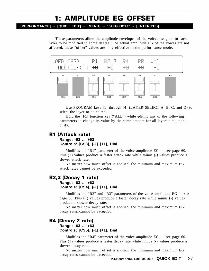
These parameters allow the amplitude envelopes of the voices assigned to eachlayer to be modified to some degree. The actual amplitude EG of the voices are notaffected, these “offset” values are only effective in the performance mode.
1: AMPLITUDE EG OFFSET[PERFORMANCE] → [QUICK EDIT] → [MENU] → 1:AEG Offset → [ENTER/YES]
Use PROGRAM keys [1] through [4] (LAYER SELECT A, B, C, and D) toselect the layer to be edited.
Hold the [F1] function key (“ALL”) while editing any of the followingparameters to change its value by the same amount for all layers simultane-ously.
R1 (Attack rate)Range: -63 … +63Controls: [CS3], [-1] [+1], Dial
Modifies the “R1” parameter of the voice amplitude EG — see page 60.Plus (+) values produce a faster attack rate while minus (-) values produce aslower attack rate.
No matter how much offset is applied, the minimum and maximum EGattack rates cannot be exceeded.
R2,3 (Decay 1 rate)Range: -63 … +63Controls: [CS4], [-1] [+1], Dial
Modifies the “R2” and “R3” parameters of the voice amplitude EG — seepage 60. Plus (+) values produce a faster decay rate while minus (-) valuesproduce a slower decay rate.
No matter how much offset is applied, the minimum and maximum EGdecay rates cannot be exceeded.
R4 (Decay 2 rate)Range: -63 … +63Controls: [CS5], [-1] [+1], Dial
Modifies the “R4” parameter of the voice amplitude EG — see page 60.Plus (+) values produce a faster decay rate while minus (-) values produce aslower decay rate.
No matter how much offset is applied, the minimum and maximum EGdecay rates cannot be exceeded.
F1
CS1
F2
CS2
F3
CS3
F4
CS4
F5
CS5
F6
CS6
F7
CS7
F8
CS8
QED`AEG)````R1``R2,3``R4```RR``Vel
`ALL[Lyr:A]`+0```+0```+0```+0```+0

28 PERFORMANCE EDIT MODE / QUICK EDIT
RR (Release rate)Range: -63 … +63Controls: [CS6], [-1] [+1], Dial
Modifies the “RR” parameter of the voice amplitude EG — see page 60.Plus (+) values produce a faster release rate while minus (-) values produce aslower release rate.
No matter how much offset is applied, the minimum and maximum EGrelease rates cannot be exceeded.
Vel (Velocity sensitivity)Range: -14 ... +14Controls: [CS7], [-1] [+1], Dial
Modifies the amplitude EG velocity sensitivity setting (see page 63). Plus“+” settings increase sensitivity while minus “-” settings reduce sensitivity.
No matter how much offset is applied, the minimum and maximum velocityvalues cannot be exceeded.

29PERFORMANCE EDIT MODE / QUICK EDIT
These parameters allow the main LFO and filter parameters of the voices assignedto each layer to be modified to some degree. The actual LFO and filter parameters ofthe voices are not affected, these “offset” values are only effective in the performancemode.
2: LFO & FILTER OFFSET[PERFORMANCE] → [QUICK EDIT] → [MENU] → 2:LFO,Filter Offset → [ENTER/YES]
Use PROGRAM keys [1] through [4] (LAYER SELECT A, B, C, and D) toselect the layer to be edited.
Hold the [F1] function key (“ALL”) while editing any of the followingparameters to change its value by the same amount for all layers simultane-ously.
Speed (LFO speed)Range: -99 … +99Controls: [CS3], [-1] [+1], Dial
Modifies the speed of the LFO (this corresponds to the “Speed” parameterof the main voice LFO — see page 78). Plus (+) values increase the LFOspeed while minus (-) values reduce the speed.
No matter how much offset is applied, the minimum and maximum LFOspeeds cannot be exceeded.
Depth (LFO depth)Range: -99 … +99Controls: [CS4], [-1] [+1], Dial
Modifies the amplitude, pitch, and frequency modulation depth of the LFO(this corresponds to the “Pmod”, “Amod”, and “Fmod” parameters of the mainvoice LFO — see page 78 and 79). Plus (+) values produce greater modulationdepth while minus (-) values reduce the modulation depth.
No matter how much offset is applied, the minimum and maximum LFOdepth values cannot be exceeded.
F1
CS1
F2
CS2
F3
CS3
F4
CS4
F5
CS5
F6
CS6
F7
CS7
F8
CS8
QED``LFO)Speed`Depth`Fltr)Coff`Reso``Vel
`ALL[Lyr:C]`+0```+0``````----``---```+0

30 PERFORMANCE EDIT MODE / QUICK EDIT
Coff (Filter cutoff frequency)Range: -127 … +127Controls: [CS6], [-1] [+1], Dial
Modifies the filter cutoff frequency (this corresponds to the voice filter“CutOff” parameter — see page 65). Plus (+) values increase the cutoff fre-quency while minus (-) values lower the cutoff frequency. This parametercannot be used if the filter is set to “Thru”. In this case “----” appears in placeof the parameter value.
No matter how much offset is applied, the minimum and maximum cutofffrequency values cannot be exceeded.
Reso (Filter resonance)Range: -99 … +99Controls: [CS7], [-1] [+1], Dial
Modifies the height of the filter’s resonant peak (this corresponds to thefilter “Resonance” parameter — see page 68). Plus (+) values increase reso-nance while minus (-) values reduce resonance. This parameter cannot be usedif the filter is not set to “LPF”. In this case “---” appears in place of the pa-rameter value.
No matter how much offset is applied, the minimum and maximum reso-nance values cannot be exceeded.
Vel (Velocity sensitivity)Range: -127 ... +127Controls: [CS8], [-1] [+1], Dial
Modifies the filter velocity sensitivity setting (see page 72). Plus “+” set-tings increase sensitivity while minus “-” settings reduce sensitivity.
No matter how much offset is applied, the minimum and maximum velocityvalues cannot be exceeded.

31PERFORMANCE EDIT MODE / QUICK EDIT
These parameters determine how the performance layers are affected by keyboardaftertouch response, the modulation wheel, and the foot controller.
3: CONTROLLER CONDITIONS[PERFORMANCE] → [QUICK EDIT] → [MENU] → 3:Controller Condition → [ENTER/YES]
Use PROGRAM keys [1] through [4] (LAYER SELECT A, B, C, and D) toselect the layer to be edited.
Hold the [F1] function key (“ALL”) while editing any of the followingparameters to change its value by the same amount for all layers simultane-ously.
AT (Aftertouch)Range: off, LyrA, LyrB, LyrC, LyrDControls: [CS3], [-1] [+1], Dial
The aftertouch control settings from the voice assigned to the selected layer(LyrA, LyrB, LyrC, or LyrD) are applied to the layer being edited (i.e. thelayer selected via PROGRAM keys [1] through [4]). Select “off” to turnaftertouch control off for the layer being edited.
MW (Modulation wheel)Range: off, LyrA, LyrB, LyrC, LyrDControls: [CS4], [-1] [+1], Dial
The modulation wheel control settings from the voice assigned to the se-lected layer (LyrA, LyrB, LyrC, or LyrD) are applied to the layer being edited(i.e. the layer selected via PROGRAM keys [1] through [4]). Select “off” toturn modulation wheel control off for the layer being edited.
FC (Foot controller)Range: off, LyrA, LyrB, LyrC, LyrDControls: [CS6], [-1] [+1], Dial
The foot controller control settings from the voice assigned to the selectedlayer (LyrA, LyrB, LyrC, or LyrD) are applied to the layer being edited (i.e.the layer selected via PROGRAM keys [1] through [4]). Select “off” to turnfoot control off for the layer being edited.
F1
CS1
F2
CS2
F3
CS3
F4
CS4
F5
CS5
F6
CS6
F7
CS7
F8
CS8
QED`CTRL)Use`AT``MW```FC`````AT>MW`MW>AT
`ALL[Lyr:A]LyrA`LyrA`LyrA``````off``off

32 PERFORMANCE EDIT MODE / QUICK EDIT
AT>MW (Aftertouch modulation wheel)Range: off, onControls: [CS7], [-1] [+1], Dial
When this parameter is turned “on,” aftertouch can be used to prouce thesame effect as the modulation wheel, in addition to any parameters assigned toaftertouch.
MW>AT (Modulation wheel aftertouch)Range: off, onControls: [CS8], [-1] [+1], Dial
When this parameter is turned “on,” the modulation wheel can be used toproduce the same effect as aftertouch, in addition to any parameters assigned tothe modulation wheel.

33PERFORMANCE EDIT MODE / QUICK EDIT
Other parameters that can be individually set for each performance layer areprovided in this screen: sustain enable, pitch envelope generator enable, oscillatorfixed note mode and note number.
4: OTHER CONDITIONS[PERFORMANCE] → [QUICK EDIT] → [MENU] → 4:Other Condition → [ENTER/YES]
Use PROGRAM keys [1] through [4] (LAYER SELECT A, B, C, and D) toselect the layer to be edited.
Hold the [F1] function key (“ALL”) while editing any of the followingparameters to change its value by the same amount for all layers simultane-ously.
SustainRange: off, onControls: [CS4], [-1] [+1], Dial
Turns sustain off or on for the selected layer. Interesting effects can beproduced by setting some layers to respond to the sustain footswitch in thenormal way, while others do not sustain at all.
PEG (Pitch EG enable)Range: off, onControls: [CS5], [-1] [+1], Dial
Turns pitch envelope generator control of the selected layer off or on.
Fix (Oscillator fix)Range: off, onControls: [CS6], [-1] [+1], Dial
Turns the oscillator fixed-pitch mode on or off (see page 58). The FixNoteparameter described below can be used to set the note produced when the “fix”mode is turned on.
F1
CS1
F2
CS2
F3
CS3
F4
CS4
F5
CS5
F6
CS6
F7
CS7
F8
CS8
QED`OTHER)``Sustain``PEG``Fix`FixNote
`ALL[Lyr:A]``````on```on``off``---

34 PERFORMANCE EDIT MODE / QUICK EDIT
FixNote (Oscillator fix note number)Range: C-2 … G8Controls: [CS7], [-1] [+1], Dial
Sets the frequency (note) at which the selected layer will be played whenthe “fix” mode is turned on (“---” is displayed in place of the note when the“fix” mode is turned off).
The C-2 to G8 range of this parameter covers a full 10-1/2 octaves. “C3”corresponds to “middle C” on a keyboard.

35PERFORMANCE EDIT MODE / QUICK EDIT
The SY85 features a complex, high-performance effect system that can be pro-grammed easily via the parameters presented here and in the following screen.
For a complete list of effect parameters see page 274.
5: EFFECT TYPE[PERFORMANCE] → [QUICK EDIT] → [MENU] → 5:Effect Type → [ENTER/YES]
Effect Type 1/2Range: 0 … 90Controls: [CS1]/[CS4], [-1] [+1], Dial
[CS1] selects any of the SY85’s 90 effect types for the EFFECT 1 proces-sor, and [CS4] does the same for the EFFECT 2 processor. See page 254 formore details on the SY85 effect system.
Wet Balance 1/2Range: 0 … 100Controls: [CS7]/[CS8], [-1] [+1], Dial
[CS7] controls the balance between the direct no-effect sound and the effectsound of the EFFECT 1 processor, while [CS8] does the same for the EFFECT2 processor. The higher the value the deeper the effect. See page 254 for moredetails on the SY85 effect system.
F1
CS1
F2
CS2
F3
CS3
F4
CS4
F5
CS5
F6
CS6
F7
CS7
F8
CS8
QED`EFFECT)```Type```````````Wet`Balance
``06:Rev.Stage1``57:EQ`->`Sym```50%``50%

36 PERFORMANCE EDIT MODE / QUICK EDIT
6: EFFECT PARAMETER[PERFORMANCE] → [QUICK EDIT] → [MENU] → 6:Effect Param → [ENTER/YES]
This screen provides access to the four main parameters each for the currentselected effect 1 and effect 2. The four effect 1 parameters are edited via [CS1]through [CS4], while the four effect 2 parameters are edited via [CS5] through [CS8].
The parameters are different for each effect (refer to page 274 for details). TheEFFECT mode PARAMETERS screen described on page 44 provides full access toall 8 effect parameters.
F1
CS1
F2
CS2
F3
CS3
F4
CS4
F5
CS5
F6
CS6
F7
CS7
F8
CS8
QED`EF`PARAM)`<`1:Stge>``)Rev.Time``[s](
`2.5``1.0```45`12.0```+0```+0``0.8``100
37PERFORMANCE EDIT MODE / EFFECT EDIT
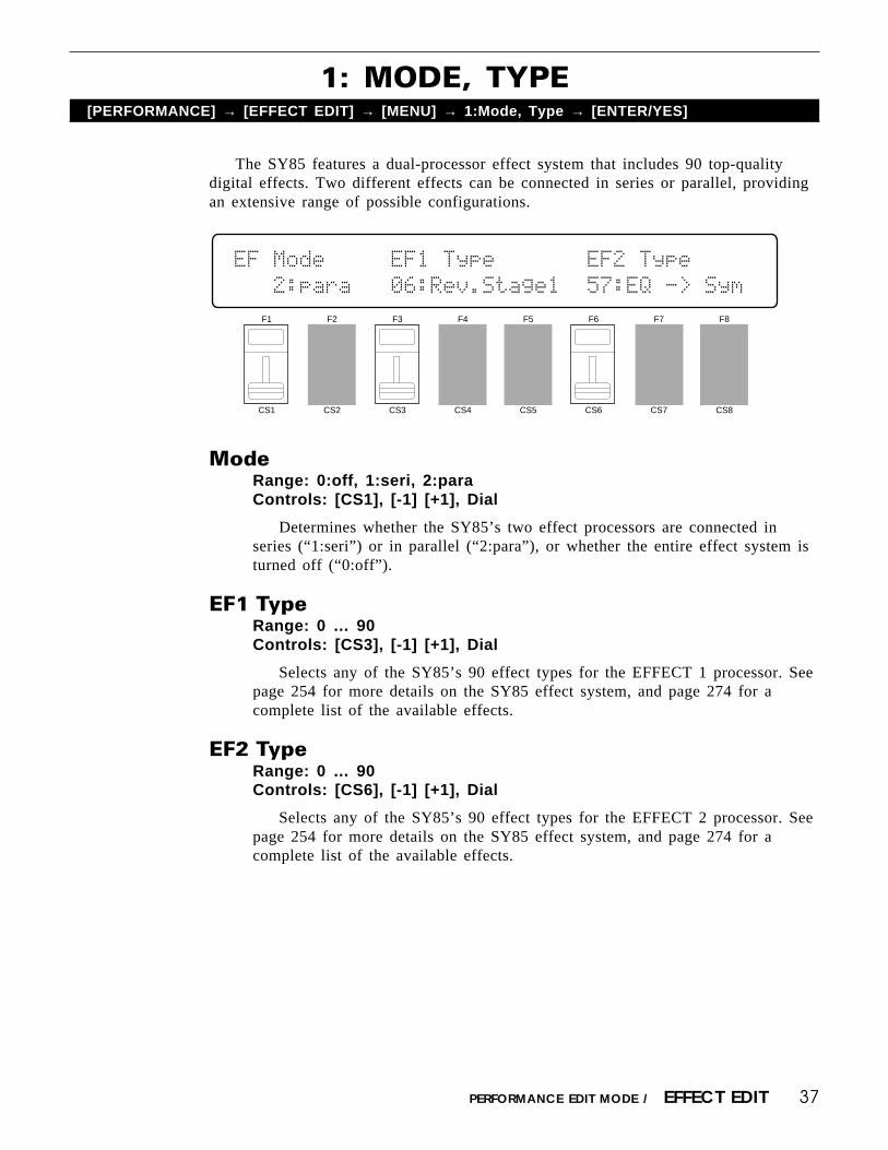
1: MODE, TYPE[PERFORMANCE] → [EFFECT EDIT] → [MENU] → 1:Mode, Type → [ENTER/YES]
The SY85 features a dual-processor effect system that includes 90 top-qualitydigital effects. Two different effects can be connected in series or parallel, providingan extensive range of possible configurations.
ModeRange: 0:off, 1:seri, 2:paraControls: [CS1], [-1] [+1], Dial
Determines whether the SY85’s two effect processors are connected inseries (“1:seri”) or in parallel (“2:para”), or whether the entire effect system isturned off (“0:off”).
EF1 TypeRange: 0 … 90Controls: [CS3], [-1] [+1], Dial
Selects any of the SY85’s 90 effect types for the EFFECT 1 processor. Seepage 254 for more details on the SY85 effect system, and page 274 for acomplete list of the available effects.
EF2 TypeRange: 0 … 90Controls: [CS6], [-1] [+1], Dial
Selects any of the SY85’s 90 effect types for the EFFECT 2 processor. Seepage 254 for more details on the SY85 effect system, and page 274 for acomplete list of the available effects.
F1
CS1
F2
CS2
F3
CS3
F4
CS4
F5
CS5
F6
CS6
F7
CS7
F8
CS8
EF`Mode`````EF1`Type```````EF2`Type``
```2:para```06:Rev.Stage1``57:EQ`->`Sym

38 PERFORMANCE EDIT MODE / EFFECT EDIT
The parameters provided here determine to which of the SY85 effect stages theoutput from the voice assigned to each layer is sent, and at what level. It is alsopossible to control the effect send level via keyboard dynamics and key scaling.
2: SEND SELECT & LEVEL[PERFORMANCE] → [EFFECT EDIT] → [MENU] → 2:Send → [ENTER/YES]
LayerRange: A, B, C, DControls: [CS2], PROGRAM [1] … [4], [-1] [+1], Dial
Selects the layer to be edited. The name of the voice assigned to the se-lected layer is shown between parentheses on the upper line of the display.
Switch 1a, 1b/2a, 2bRange: See text below.Controls: [CS4]/[CS5], [-1] [+1], Dial
Determines to which of the EFFECT 1 and EFFECT 2 effect stages theoutput from the current layer is sent. The [-1] and [+1] keys can then be usedto turn the stage on (“a” or “b”) or off (“.”). The [CS4] and [CS5] slidersselect the following settings in sequence:
CS4 (EFFECT 1) CS5 (EFFECT 2)
1./. (a and b off) 2./. (a and b off)1a/. (a on, b off) 2a/. (a on, b off)1a/b (a and b on) 2a/b (a and b on)1./b (a off, b on) 2./b (a off, b on)
If a “single” type effect is selected then only stage “a” can be selected. If a“dual” or “cascade” type effect is selected, then both stages “a” and “b” can beselected. An effect stage that cannot be selected is represented by “-” on thedisplay.
F1
CS1
F2
CS2
F3
CS3
F4
CS4
F5
CS5
F6
CS6
F7
CS7
F8
CS8
EF`Send`<InitVce`>`Switch`Levl`VelS`Kscl
``Layer=A(¡A1)```1a/-`2a/b`127```+0```+0

39PERFORMANCE EDIT MODE / EFFECT EDIT
Send (Send level)Range: 0 … 127Controls: [CS6], [-1] [+1], Dial
This parameter adjusts the amount of direct voice signal that is sent to theeffect processors, determining the strength of the final effect sound. A settingof “0” results in no effect, leaving only the “dry” sound of the voice. Themaximum setting of “127” produces the maximum amount of effect.
VelS (Send velocity sensitivity)Range: -7 … +7Controls: [CS7], [-1] [+1], Dial
Determines how the send level from the selected layer is affected by veloc-ity changes (e.g. keyboard dynamics).
Plus “+” settings produce higher send levels in response to higher velocityvalues — i.e. the harder a key is played, the higher the send level, and there-fore the deeper the effect. The maximum setting of “+7” produces the maxi-mum level variation in response to velocity changes. Minus “-” settings producethe opposite effect: lower send level in response to higher velocity. A setting of“+0” results in no send level variation.
Kscl (Send key scaling)Range: -7 … +7Controls: [CS8], [-1] [+1], Dial
Allows the send level for the selected layer to be varied across the entirepitch range (i.e. keyboard range).
Plus (“+”) settings produce a higher send level for the low notes and alower send level for the high notes. The maximum “+7” setting produces thegreatest send level variation across the pitch range. Minus (“-”) settings pro-duce the opposite effect — a lower low-note send level and higher high-notesend level. A setting of “+0” results in no send level variation.
40
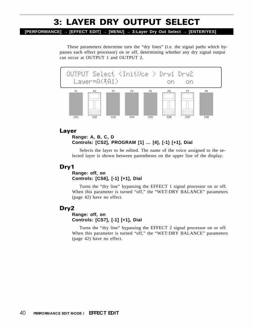
These parameters determine turn the “dry lines” (i.e. the signal paths which by-passes each effect processor) on or off, determining whether any dry signal outputcan occur at OUTPUT 1 and OUTPUT 2.
3: LAYER DRY OUTPUT SELECT[PERFORMANCE] → [EFFECT EDIT] → [MENU] → 3:Layer Dry Out Select → [ENTER/YES]
LayerRange: A, B, C, DControls: [CS2], PROGRAM [1] … [4], [-1] [+1], Dial
Selects the layer to be edited. The name of the voice assigned to the se-lected layer is shown between parentheses on the upper line of the display.
Dry1Range: off, onControls: [CS6], [-1] [+1], Dial
Turns the “dry line” bypassing the EFFECT 1 signal processor on or off.When this parameter is turned “off,” the “WET:DRY BALANCE” parameters(page 42) have no effect.
Dry2Range: off, onControls: [CS7], [-1] [+1], Dial
Turns the “dry line” bypassing the EFFECT 2 signal processor on or off.When this parameter is turned “off,” the “WET:DRY BALANCE” parameters(page 42) have no effect.
PERFORMANCE EDIT MODE / EFFECT EDIT
F1
CS1
F2
CS2
F3
CS3
F4
CS4
F5
CS5
F6
CS6
F7
CS7
F8
CS8
OUTPUT`Select`<InitVce`>`Dry1`Dry2`
``Layer=A(¡A1)`````````````on```on

41PERFORMANCE EDIT MODE / EFFECT EDIT
Depending on the selected effects the SY85 effect system can have up to fourseparate output levels that are adjusted by the parameters provided in this screen.
4: OUTPUT LEVEL[PERFORMANCE] → [EFFECT EDIT] → [MENU] → 4:Output Level → [ENTER/YES]
1a, 1b, 2a, and 2b (Effect output levels)Range: 0 … 100Controls: [CS3], [CS4], [CS7], [CS8], [-1] [+1], Dial
The [CS3] and [CS4] sliders adjust the output levels of the effect 1 “1a”and “1b” stages, respectively, while the [CS7] and [CS8] sliders adjust theoutput levels of the effect 2 “2a” and “2b” stages. A setting of “0” turns outputfrom the corresponding effect stage off, while a setting of “100” producesmaximum output level.
If the selected effect is a “single” type, then only the “1a” or “2a” outputlevel is available. If it is a “cascade” type, then only the “1b” or “2b” outputlevel is available. Both the “1a” and “1b” or “2a” and “2b” levels are availableonly if the selected effect is a “dual” type. The type of the effects currentlyselected for the effect 1 and effect 2 processors are shown in parentheses onthe bottom line of the display. See page 254 for details on the effect stages andthe SY85 effect system in general.
If a controller is assigned to any of the output level parameters (page 45),an inverse “c” will appear to the right of the parameter.
F1
CS1
F2
CS2
F3
CS3
F4
CS4
F5
CS5
F6
CS6
F7
CS7
F8
CS8
EF`OutLevel`1a```1b`````````````2a```2b`
`EF1(sngl)=100%``--`EF2(casc)=``--``100%

42 PERFORMANCE EDIT MODE / EFFECT EDIT
5: WET:DRY BALANCE[PERFORMANCE] → [EFFECT EDIT] → [MENU] → 5:Wet:Dry Balance → [ENTER/YES]
The balance between the direct sound of the voice and the effect sound is adelicate thing. Even slight changes can make a big difference to the final sound. Theparameters provided in this screen provide precise balance control.
Out1 Wet/Out2 WetRange: 0 … 100Controls: [CS3]/[CS7], [-1] [+1], Dial
These parameters and the corresponding “Out1 Dry” and “Out2 Dry” pa-rameters, below, work together to balance the effect (“wet”) and direct (“dry”)signals delivered via the EFFECT 1 and EFFECT2 processors. Higher “Wet”values produce more effect sound in relation to the direct, dry sound of thevoice.
Although the “Wet” and “Dry” parameters can be set independently, adjust-ing one will cause the other to change so that their total is always 100(%).
If a controller is assigned to the “Out1 Wet” or “Out2 Wet” parameter(page 45), an inverse “c” will appear to the right of the parameter.
Out1 Dry/Out2 DryRange: 0 … 100Controls: [CS4]/[CS8], [-1] [+1], Dial
These parameters and the corresponding “Out1 Wet” and “Out2 Wet” pa-rameters, above, work together to balance the effect (“wet”) and direct (“dry”)signals delivered via the EFFECT 1 and EFFECT 2 processors, respectively.Higher “Dry” values produce more direct, dry sound in relation to the effectsound.
Although the “Wet” and “Dry” parameters can be set independently, adjust-ing one will cause the other to change so that their total is always 100(%).
If a controller is assigned to the “Out1 Dry” or “Out2 Dry” parameter (page45), an inverse “c” will appear to the right of the parameter.
F1
CS1
F2
CS2
F3
CS3
F4
CS4
F5
CS5
F6
CS6
F7
CS7
F8
CS8
EF`Wet:Dry`Balance`````
`````Out1=``50`:`50``````Out2=``50`:`50

43PERFORMANCE EDIT MODE / EFFECT EDIT
These parameters determine the mix level between each effect send and the outputof the preceding effect stage. Refer to the section beginning on page 254 for detailson the overall SY85 effect system.
6: SEND & EFFECT 2 MIX LEVEL[PERFORMANCE] → [EFFECT EDIT] → [MENU] → 6:Mix Level → [ENTER/YES]
EF2 Mix (Effect 2 mix level)Range: 0 … 100Controls: [CS4], [-1] [+1], Dial
Mixes the output of the EFFECT 2 processor with that of the EFFECT 1processor. This parameter can only be used with the “serial” effect mode isselected. If any other mode is selected (“off” or “para”), “---” appears on thedisplay in place of the value.
If a controller is assigned to the EF2 Mix parameter (page 45), an inverse“c” will appear to the right of the parameter.
Insert 1b, 2a, 2b (Insert level)Range: 0 … 100Controls: [CS6], [CS7], [CS8], [-1] [+1], Dial
These parameters mix the dry signal sent to the corresponding effect stagewith the output of the preceding effect stage. The higher the value the greatermix level. If the current effect configuration does not allow one of these mixparameters, “--” will appear in place of the mix level parameter.
If a controller is assigned to the one of these parameters (page 45), aninverse “c” will appear to the right of the parameter.
F1
CS1
F2
CS2
F3
CS3
F4
CS4
F5
CS5
F6
CS6
F7
CS7
F8
CS8
EF`Mix`Level```EF2``Insert`1b```2a```2b`
````````````````--`````````--```--````0%

44 PERFORMANCE EDIT MODE / EFFECT EDIT
7: EFFECT 1 PARAMETERS8: EFFECT 2 PARAMETERS
[PERFORMANCE] → [EFFECT EDIT] → [MENU] → 7:EF1 Parameter → [ENTER/YES]→ 8:EF2 Parameter → [ENTER/YES]
Each of the SY85’s 90 effects has 8 parameters that can be edited via the param-eters in this screen to fine-tune the effect.
Each parameter is controlled by the corresponding slider (i.e. the sliderimmediately below each parameter). The [-1]/[+1] keys and data entry dial canalso be used to edit the parameter at which the cursor is currently located.
Refer to page 274 for a complete listing of the parameters provided foreach effect.
F1
CS1
F2
CS2
F3
CS3
F4
CS4
F5
CS5
F6
CS6
F7
CS7
F8
CS8
EF1`PARAM`<Rev.Stage1>```)ER/Rev`Bal[%](
`2.5``1.0```10```32```16````4````0`12.0
45PERFORMANCE EDIT MODE / EFFECT EDIT
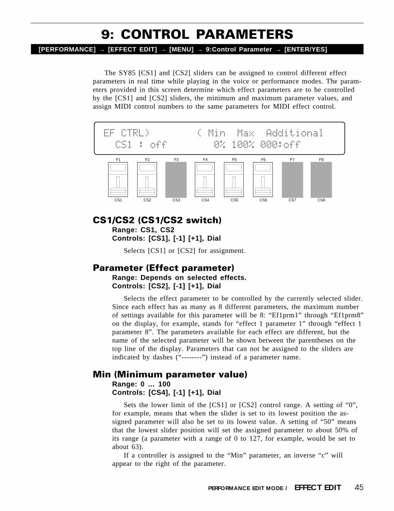
The SY85 [CS1] and [CS2] sliders can be assigned to control different effectparameters in real time while playing in the voice or performance modes. The param-eters provided in this screen determine which effect parameters are to be controlledby the [CS1] and [CS2] sliders, the minimum and maximum parameter values, andassign MIDI control numbers to the same parameters for MIDI effect control.
9: CONTROL PARAMETERS[PERFORMANCE] → [EFFECT EDIT] → [MENU] → 9:Control Parameter → [ENTER/YES]
CS1/CS2 (CS1/CS2 switch)Range: CS1, CS2Controls: [CS1], [-1] [+1], Dial
Selects [CS1] or [CS2] for assignment.
Parameter (Effect parameter)Range: Depends on selected effects.Controls: [CS2], [-1] [+1], Dial
Selects the effect parameter to be controlled by the currently selected slider.Since each effect has as many as 8 different parameters, the maximum numberof settings available for this parameter will be 8: “Ef1prm1” through “Ef1prm8”on the display, for example, stands for “effect 1 parameter 1” through “effect 1parameter 8”. The parameters available for each effect are different, but thename of the selected parameter will be shown between the parentheses on thetop line of the display. Parameters that can not be assigned to the sliders areindicated by dashes (“--------”) instead of a parameter name.
Min (Minimum parameter value)Range: 0 … 100Controls: [CS4], [-1] [+1], Dial
Sets the lower limit of the [CS1] or [CS2] control range. A setting of “0”,for example, means that when the slider is set to its lowest position the as-signed parameter will also be set to its lowest value. A setting of “50” meansthat the lowest slider position will set the assigned parameter to about 50% ofits range (a parameter with a range of 0 to 127, for example, would be set toabout 63).
If a controller is assigned to the “Min” parameter, an inverse “c” willappear to the right of the parameter.
F1
CS1
F2
CS2
F3
CS3
F4
CS4
F5
CS5
F6
CS6
F7
CS7
F8
CS8
EF`CTRL)````````(`Min``Max``Additional`
``CS1`:`off````````0%`100%`000:off

46 PERFORMANCE EDIT MODE / EFFECT EDIT
Max (Maximum parameter value)Range: 0 … 100Controls: [CS5], [-1] [+1], Dial
Sets the upper limit of the [CS1] or [CS2] control range. A setting of“100”, for example, means that when the slider is set to its highest position theassigned parameter will also be set to its highest value. A setting of “80”means that the highest slider position will set the assigned parameter to about80% of its range (a parameter with a range of 0 to 127, for example, would beset to about 102).
If a controller is assigned to the “Max” parameter, an inverse “c” willappear to the right of the parameter.
Additional (Additional MIDI control)Range: 000 … 120, AfterTch, Velocity, KeyScale, LFOControls: [CS6], [-1] [+1], Dial
This parameter allows MIDI control change numbers to be assigned to theselected effect parameters, so that they can be controlled from the SY85 con-trollers (modulation wheel, foot controller, etc) or an external MIDI device thatis capable of transmitting control change messages. Additional settings include“AfterTch” for keyboard aftertouch control, “Velocity” for keyboard velocitycontrol, “KeyScale” for key scaling control, and “LFO” for internal LFO con-trol. This is in addition to control via the [CS1] and [CS2] sliders. MIDI con-trol change numbers 000 through 120 can be assigned. Some control changenumbers are already defined, while others are not assigned to any specificcontroller (see chart below).
MIDI CONTROL CHANGE NUMBER/DEVICE
0: “--------”1: “Mod.Whl.”2: “Breath C”4: “Foot Cnt”5: “Porta.Tm”6: “Data Ent”7: “Main Vol”8: “Balance ”10: “Panpot ”11: “Express.”64: “Hold 1 ”65: “Porta.Sw”66: “Sostenut”67: “Soft ”69: “Hold 2 ”
91: “Effect D”92: “TremoloD”93: “Chorus D”94: “CelesteD”95: “Phaser D”96: “Inc. ”97: “Dec. ”98: “NRPN LSB”99: “NRPN MSB”100: “RPN LSB”101: “RPN MSB”121: “AfterTch”122: “Velocity”123: “KeyScale”124: “LFO ”
47PERFORMANCE EDIT MODE / EFFECT EDIT
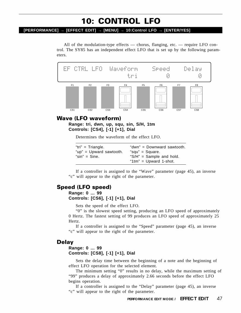
All of the modulation-type effects — chorus, flanging, etc. — require LFO con-trol. The SY85 has an independent effect LFO that is set up by the following param-eters.
10: CONTROL LFO[PERFORMANCE] → [EFFECT EDIT] → [MENU] → 10:Control LFO → [ENTER/YES]
F1
CS1
F2
CS2
F3
CS3
F4
CS4
F5
CS5
F6
CS6
F7
CS7
F8
CS8
EF`CTRL`LFO``Waveform````Speed````Delay`
``````````````∆˚∆`tri````````0````````0
Wave (LFO waveform)Range: tri, dwn, up, squ, sin, S/H, 1tmControls: [CS4], [-1] [+1], Dial
Determines the waveform of the effect LFO.
“tri” = Triangle. “dwn” = Downward sawtooth.“up” = Upward sawtooth. “squ” = Square.“sin” = Sine. “S/H” = Sample and hold.
“1tm” = Upward 1-shot.
If a controller is assigned to the “Wave” parameter (page 45), an inverse“c” will appear to the right of the parameter.
Speed (LFO speed)Range: 0 … 99Controls: [CS6], [-1] [+1], Dial
Sets the speed of the effect LFO.“0” is the slowest speed setting, producing an LFO speed of approximately
0 Hertz. The fastest setting of 99 produces an LFO speed of approximately 25Hertz.
If a controller is assigned to the “Speed” parameter (page 45), an inverse“c” will appear to the right of the parameter.
DelayRange: 0 … 99Controls: [CS8], [-1] [+1], Dial
Sets the delay time between the beginning of a note and the beginning ofeffect LFO operation for the selected element.
The minimum setting “0” results in no delay, while the maximum setting of“99” produces a delay of approximately 2.66 seconds before the effect LFObegins operation.
If a controller is assigned to the “Delay” parameter (page 45), an inverse“c” will appear to the right of the parameter.

48 PERFORMANCE EDIT MODE / EFFECT EDIT
[PERFORMANCE] → [EFFECT EDIT] → [COPY]
This function facilitates performance effect editing by allowing the effect param-eters from any other song, voice, or performance combination to be copied to thecurrent performance combination. You can copy an effect setup that is close to thetype you want, then edit it to produce the required sound.
FromRange: Any song, voice or performance combinationControls: MEMORY, GROUP, PROGRAM, [CS5], [-1] [+1], Dial
Use the [INTERNAL 1], [INTERNAL 2], and [CARD] MEMORY keys toselect the memory area from which the source voice is to be selected. Use theGROUP keys to select the source voice bank, then use the PROGRAM keys toselect the source voice number. The [CS5] slider and other data entry controlscan also be used to select the source voice number.
Once the source voice has been selected, press the [ENTER/YES] key. “Areyou sure?” will appear on the display.
F1
CS1
F2
CS2
F3
CS3
F4
CS4
F5
CS5
F6
CS6
F7
CS7
F8
CS8
EFFECT`COPY`````From
````````````````PFM``¡A1:InitPerf```````
EFFECT DATA COPY
EFFECT`COPY`````From
Are`you`sure`?``PFM``¡A1:InitPerf
Press the [ENTER/YES] key again to copy the effect data, or press [EXIT/NO] to cancel the copy operation. Once the copy operation has finished, “Com-pleted!” will appear on the display briefly, then the display will return to theeffect edit mode.
49PERFORMANCE EDIT MODE / EFFECT EDIT
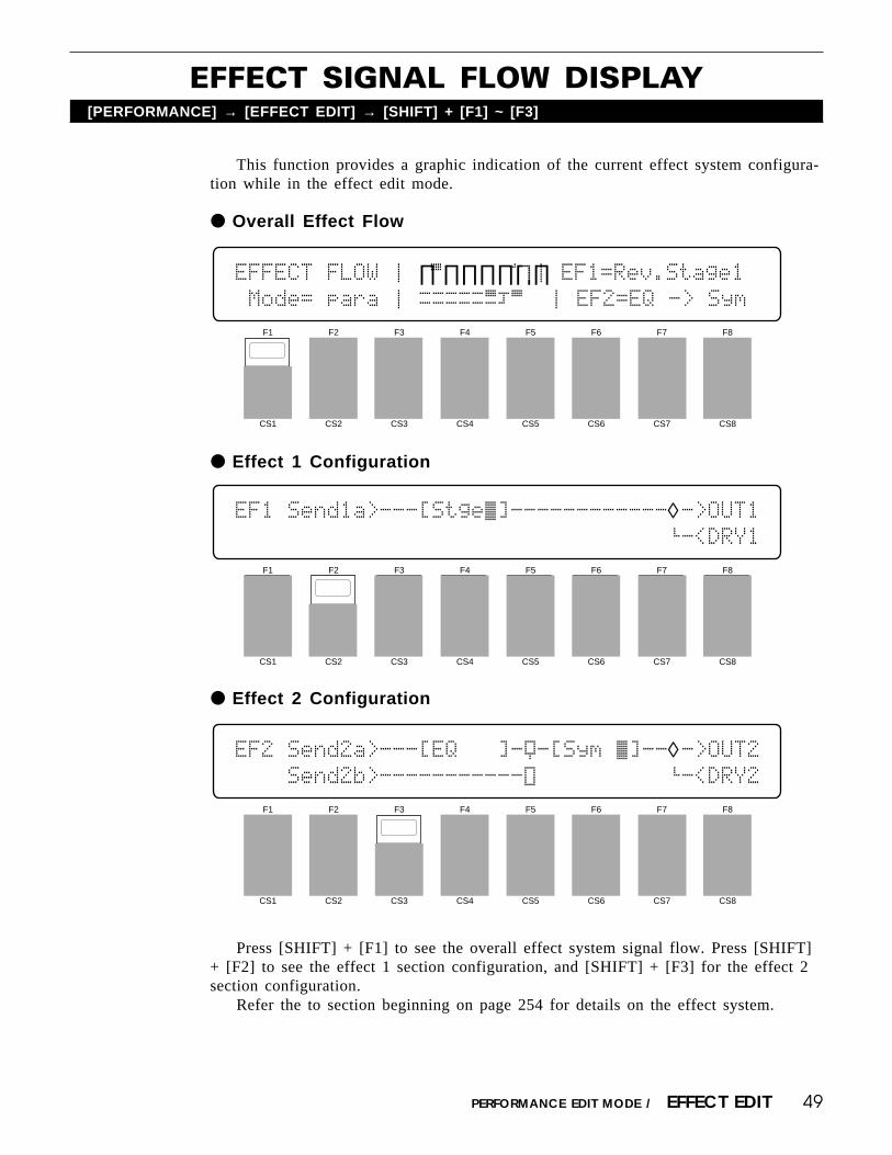
EFFECT SIGNAL FLOW DISPLAY[PERFORMANCE] → [EFFECT EDIT] → [SHIFT] + [F1] ~ [F3]
This function provides a graphic indication of the current effect system configura-tion while in the effect edit mode.
Overall Effect Flow
Effect 1 Configuration
Press [SHIFT] + [F1] to see the overall effect system signal flow. Press [SHIFT]+ [F2] to see the effect 1 section configuration, and [SHIFT] + [F3] for the effect 2section configuration.
Refer the to section beginning on page 254 for details on the effect system.
Effect 2 Configuration
F1
CS1
F2
CS2
F3
CS3
F4
CS4
F5
CS5
F6
CS6
F7
CS7
F8
CS8
EFFECT`FLOW`Ú`∏Á∏∏∏∏∏∏Î`Ú`EF1=Rev.Stage1
`Mode=`para`Ú`ØØØØØËÔÁ `Ú`EF2=EQ`->`Sym
F1
CS1
F2
CS2
F3
CS3
F4
CS4
F5
CS5
F6
CS6
F7
CS7
F8
CS8
EF1`Send1a>---[Stge˜]------------◊->OUT1`````````````````````````````````’-<DRY1
F1
CS1
F2
CS2
F3
CS3
F4
CS4
F5
CS5
F6
CS6
F7
CS7
F8
CS8
EF2`Send2a>---[EQ```]-Ÿ-[Sym`˜]--◊->OUT2````Send2b>-----------Û``````````’-<DRY2

50 PERFORMANCE EDIT MODE / JOB
1: LAYER CONTROLLER SYNC[PERFORMANCE] → [JOB] → [MENU] → 1:Layer Controller Sync → [ENTER/YES]
This function changes the controller parameters of all voices in the selectedperfomance combination to match those of the voice assigned to the specified“source” layer.
Use the [CS8] slider to select the source layer (A, B, C, or D) from whichthe controller data is to be copied, then press [ENTER/YES] to begin the layercontroller sync procedure. The following confirmation display will appear:
F1
CS1
F2
CS2
F3
CS3
F4
CS4
F5
CS5
F6
CS6
F7
CS7
F8
CS8
PERFORMANCE`JOB`Layer`Controller`Sync```
``````````````````````````Source`LayerA
PERFORMANCE`JOB`Layer`Controller`Sync
Are`you`sure`?````````````Source`LayerA
Press [ENTER/YES] again to confirm that you want to go ahead with theoperation (which will overwrite all controller data for the voices assigned to alllayers other than the source layer), or press [EXIT/NO] to cancel.
When the data has been copied, “Completed!” will appear briefly on thedisplay, then the display will return to the mode that was engaged prior tocalling the layer controller sync function.

51PERFORMANCE EDIT MODE / JOB
2: LAYER EXCHANGE[PERFORMANCE] → [JOB] → [MENU] → 2:Layer Exchange → [ENTER/YES]
This function can be used to eliminate the audible effects of slight note delaysthat can occur in the performance play mode. The notes played by layers A, B, C,and D are sounded in sequence in the performance play mode. Normally the delay isso slight that it is not audible. If a voice with a sharp attack is assigned to one of thelater layers (C or D), however, the delay can “soften” the attack of the voice. Theproblem can be overcome by using this function to exchange layers A and D, forexample, so that the voice with the strong attack is assigned to layer A instead oflayer D. Since layer A is sounded first, the sharpness of the attack will be retained.
Use the [CS7] and [CS8] sliders to select the layers to be exchanged (Athrough D), then press [ENTER/YES] to begin the layer exchange procedure.The following confirmation display will appear:
F1
CS1
F2
CS2
F3
CS3
F4
CS4
F5
CS5
F6
CS6
F7
CS7
F8
CS8
PERFORMANCE`JOB`Layer`Exchange
`````````````````````````````````A`†¥`A
PERFORMANCE`JOB`Layer`Exchange
Are`you`sure`?```````````````````A`†¥`A
Press [ENTER/YES] again to confirm that you want to go ahead with thelayer exchange operation, or press [EXIT/NO] to cancel.
When the data has been exchanged, “Completed!” will appear briefly on thedisplay, then the display will return to the mode that was engaged prior tocalling the layer exchange function.

52 PERFORMANCE EDIT MODE / JOB
3: PERFORMANCE EDIT RECALL[PERFORMANCE] → [JOB] → [MENU] → 3:Recall → [ENTER/YES]
If you’re dissatisfied with the results of edits you’ve made to a performancecombination, or have accidentally lost track of changes made, use the PERFORM-ANCE EDIT RECALL function to recall the pre-edit performance data from theSY85’s backup buffer memory.
Press [ENTER/YES] to begin the recall procedure. The following confirma-tion display will appear:
PERFORMANCE`JOB`Recall````````<InitPerf>
Are`you`sure`?
Press [ENTER/YES] again to confirm that you want to go ahead with therecall operation (which will erase all current edited data), or press [EXIT/NO]to cancel.
When the original voice data has been recalled, “Completed!” will appearbriefly on the display, then the display will return to the mode that was en-gaged prior to calling the performance edit recall function.
F1
CS1
F2
CS2
F3
CS3
F4
CS4
F5
CS5
F6
CS6
F7
CS7
F8
CS8
PERFORMANCE`JOB`Recall````````<InitPerf>
``

53PERFORMANCE EDIT MODE / JOB
4: PERFORMANCE INITIALIZE[PERFORMANCE] → [JOB] → [MENU] → 4:Initialize → [ENTER/YES]
When you want to program a totally new performance combination “fromscratch,” rather than editing an existing combination, use this function to initialize allperformance parameters.
Press [F6] if you want to initialize the entire performance combinationcurrently in the edit buffer, or [F7] if you only want to initialize one specificlayer. If you choose [F7], use the [CS8] slider to select the layer you want toinitialize.
Press [ENTER/YES] to begin the initialize procedure. The following confir-mation display will appear:
PERFORMANCE`JOB`Initialize
Are`you`sure`?```````````[EDIT]`LYR
Press [ENTER/YES] again to confirm that you want to go ahead with theinitialize operation (which will erase all current edited data), or press [EXIT/NO] to cancel.
When the performance data has been initialized, “Completed!” will appearbriefly on the display, then the display will return to the mode that was en-gaged prior to calling the performance initialize function.
F1
CS1
F2
CS2
F3
CS3
F4
CS4
F5
CS5
F6
CS6
F7
CS7
F8
CS8
PERFORMANCE`JOB`Initialize``
`````````````````````````[EDIT]`LYR

54 PERFORMANCE EDIT MODE / COMPARE
PERFORMANCE COMPARE[SHIFT] + [STORE]
The performance compare function makes it possible to compare the sound of aperformance combination being edited with the same performance combination priorto editing.
To temporarily recall the original performance data while editing, press the[STORE] key while holding the [SHIFT] key. The [PERFORMANCE] LED willflash, indicating that the compare mode is engaged. Although you can select differentedit mode display screens, data cannot be edited in the compare mode. Press [EXIT/NO] to return to the edit mode and the performance combination being edited.
55
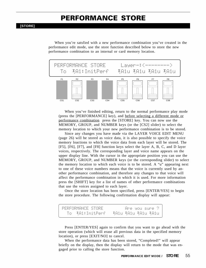
PERFORMANCE STORE[STORE]
When you’re satsfied with a new performance combination you’ve created in theperformance edit mode, use the store function described below to store the newperformance combination to an internal or card memory location.
When you’ve finished editing, return to the normal performance play mode(press the [PERFORMANCE] key), and before selecting a different mode orperformance combination press the [STORE] key. You can now use theMEMORY, GROUP, and NUMBER keys (or the [CS2] slider) to select thememory location to which your new performance combination is to be stored.
Since any changes you have made via the LAYER VOICE EDIT MENU(page 26) will be stored as voice data, it is also possible to specify the voicememory loactions to which the voice data from each layer will be stored. The[F5], [F6], [F7], and [F8] function keys select the layer A, B, C, and D layervoices, respectively. The corresponding layer and voice name appears on theupper display line. With the cursor in the appropriate position you can use theMEMORY, GROUP, and NUMBER keys (or the corresponding slider) to selectthe memory location to which each voice is to be stored. A “u” appearing nextto one of these voice numbers means that the voice is currently used by an-other performance combination, and therefore any changes to that voice willaffect the performance combination in which it is used. For more informationpress the [SHIFT] key for a list of names of other performance combinationsthat use the voices assigned to each layer.
Once the store location has been specified, press [ENTER/YES] to beginthe store procedure. The following confirmation display will appear:
F1
CS1
F2
CS2
F3
CS3
F4
CS4
F5
CS5
F6
CS6
F7
CS7
F8
CS8
PERFORMANCE`STORE`````Layer-:<-------->
``To``¡A1:InitPerf```¡A1u`¡A1u`¡A1u`¡A1u
PERFORMANCE`STORE`````````Are`you`sure`?
``To``¡A1:InitPerf```¡A1u`¡A1u`¡A1u`¡A1u
Press [ENTER/YES] again to confirm that you want to go ahead with thestore operation (which will erase all previous data in the specified memorylocation), or press [EXIT/NO] to cancel.
When the performance data has been stored, “Completed!” will appearbriefly on the display, then the display will return to the mode that was en-gaged prior to calling the store function.
PERFORMANCE EDIT MODE / STORE


VOICE EDIT MODE

58
F1
CS1
F2
CS2
F3
CS3
F4
CS4
F5
CS5
F6
CS6
F7
CS7
F8
CS8
This screen contains 6 parameters that determine the fundamental sound of thevoice being edited — including the number of the waveform on which the voice willbe based.
OSCILLATOR[VOICE] → [EDIT] → [MENU] → 1:Oscillator → [ENTER/YES]
VOICE EDIT MODE / 1:Oscillator
OSC``Wave``````Mode`Fine`Note`Rndm``Rvs`
P244`Sin```````norm```+0```+0````0``off`
WaveRange: P001 … P244, I00 … I63, C00 … C63Controls: [CS1], [-1] [+1], Dial
Selects the wave (AWM waveform) to be used in the current voice. Use the[INTERNAL 1], [INTERNAL 2], and [CARD] keys to select the memory areafrom which the wave is to be selected. Please note that when SIMM memory iswave memory installed, wave data can not be loaded into memory from awaveform card. A complete listing of the internal waves is given in the Appen-dix, on page 310.
ModeRange: fix, normControls: [CS4], [-1] [+1], Dial
Determines whether the selected wave is reproduced in the normal (variablepitch) or fixed-pitch mode.
Normally you want the pitch of the AWM wave (or waves) used in a voiceto be controllable from a keyboard or other type of controller, in which casethe “norm” mode should be selected. In some cases — sound effects in particu-lar — you might want the same pitch to be produced no matter what note youplay on the keyboard or other controller. In this case, the “fix” mode is appro-priate. The Note parameter described below can be used to set the note pro-duced when the “fix” mode is selected.
FineRange: -63 … 0 … +63Controls: [CS5], [-1] [+1], Dial
Allows fine tuning of the selected AWM wave. Each increment correspondsto approximately 1.17 cents (a “cent” is 1/100th of a semitone) so the lowestsetting (-63) shifts the pitch down by almost three quarters of a semitone, whilethe highest setting (+63) shifts the pitch up by the same amount. A setting of“+0” produces standard concert pitch (A3 = 440 Hertz).

59VOICE EDIT MODE / 1:Oscillator
Please note that this parameter is used to individually tune the currentvoice. Overall tuning control is provided by the MASTER TUNE functionavailable in the UTILITY mode.
NoteRange: C-2 … G8, -64 … +63Controls: [CS6], [-1] [+1], Dial
When the “fix” mode is selected this parameters sets the frequency (note) atwhich the selected wave will be played. The C-2 to G8 range of this parametercovers a full 10-1/2 octaves. “C3” corresponds to “middle C” on a keyboard.
When the “norm” mode is selected, this parameter is used to shift theoverall pitch of the entire keyboard up or down in semitone increments (i.e. a“note shift” function). In this case the range of the parameters is from -64through 0 to +63. A setting of “-12,” for example, shifts the pitch down by oneoctave; a setting of “+4” shifts the pitch up by a major third.
Rndm (Random pitch)Range: 0 … 7Controls: [CS7], [-1] [+1], Dial
Sets the amount of random pitch variation produced each time a note isplayed.
When this parameter is set to a value other than “0,” the pitch changesrandomly each time a note is played. The random pitch change is appliedindependently to each note in a chord. A setting of “7” produces the greatestamount of random pitch change.
This function is ideal for simulating the sound of instruments like theclavichord, string sections or other ensembles in which the pitch of each note israrely in perfect tune with the others.
Rvs (Reverse)Range: off, onControls: [CS8], [-1] [+1], Dial
When this parameter is turned “on,” the selected wave is played in reverse.When Rvs is “on,” the pitch EG “Loop” parameter described on page 75 is
automatically turned “off.”

60
1: AEG LEVEL & RATE[VOICE] → [EDIT] → [MENU] → 2:Amlitude EG → [ENTER/YES] → [ENTER/YES] →
→ [MENU] → 1:Level&Rate → [ENTER/YES]
The SY85’s main AEG (Amplitude Envelope generator) has five individuallyprogrammable rates and two levels for exceptional envelope programming flexibility.Next to the fundamental waveform used, the amplitude envelope is one of the mostimportant factors determining the overall sound of a voice.
Atk/Hld (Amplitude EG attack/hold mode)Range: atk, holdControls: [CS1], [-1] [+1], Dial
The “Atk” and “Hld” mode settings affect the initial attack of the sound,determining how the amplitude envelope begins. In the “Atk” mode, the enve-lope begins from zero level, reaching the maximum AWM level at a rate deter-mined by the R1 (Rate 1) parameter. In this mode there will always be a slightdelay between the initiation of a note and maximum level.
R1 … RR, L2 … L3 (Rates & levels)Range: 0 … 63Controls: [CS2] … [CS8], [-1] [+1], Dial
The following diagrams illustrate how the AEG rate and level parametersdetermine the overall shape of the amplitude envelope.
“Atk” Mode
VOICE EDIT MODE / 2:Amplitude EG
F1
CS1
F2
CS2
F3
CS3
F4
CS4
F5
CS5
F6
CS6
F7
CS7
F8
CS8
AEG````R1```R2```L2```R3```L3```R4```RR`
`atk``π63`ƒ`63````0`π`63```63`ƒ``0`π`50π

61
The envelope begins at zero level, reaches maximum level at the rate deter-mined by the R1 parameter, moves to L2 (Level 2) at R2 (Rate 2), moves onto L3 (Level 3) at R3 (Rate 3), and finally decays to zero level at R4 (Rate 4)if the note is held the entire time.
If the note is released before the end of the envelope described above, thenthe sound decays to zero level from the point at which the note is released atthe rate determined by the RR (Release Rate) parameter.
“Hld” Mode
If the “hold” mode is selected, the envelope begins immediately from maxi-mum AWM level, allowing the fast attack transients of waveforms to passunaffected. In this case the R1 parameter is replaced by the HT (Hold Time)parameter. The HT parameter determines the length of time between the begin-ning of the envelope and the point at which the envelope begins to movetowards L2 (Level 2) at R2 (Rate 2), as shown below.
For the level parameters, a setting of “0” corresponds to the lowest possiblelevel (no sound) while a setting of 63 produces the highest output level. A “0”rate parameter setting produces the slowest rate between levels, while themaximum setting of “63” produces the fastest (almost instantaneous) change.
VOICE EDIT MOD E / 2:Amplitude EG

62
2: LEVEL SCALING[VOICE] → [EDIT] → [MENU] → 2:Amlitude EG → [ENTER/YES] → [ENTER/YES] →
→ [MENU] → 2:Level Scaling → [ENTER/YES]
Point 1 … 4Range: C-2 ... G8Controls: [CS1] … [CS4], [-1] [+1], Dial, [SHIFT] + Keyboard
Allows four separate amplitude envelope generator level-scaling breakpointsto be set at any notes between C-2 and G8 for the selected element.
To use the keyboard for breakpoint entry, simply select a breakpoint param-eter by pressing the coresponding function key or moving the correspondingcontinuous slider, then press the key at which you want to set the breakpointwhile holding the [SHIFT] key.
No breakpoint can be set to a key lower than the breakpoint to its left.
Offset 1 … 4Range: -127 ... +127Controls: [CS5] … [CS8], [-1] [+1], Dial
Sets the amount of level offset for each of the four level-scaling break-points set by the “Point” parameters described above.
Negative values reduce the level, and positive values increase the level atthe corresponding breakpoint. No matter what value is chosen, the EG levelwill never exceed its minimum or maximum levels. When different offsetvalues are applied to adjacent breakpoints, the level varies smoothly betweenthe breakpoints.
Level scaling produces natural level variations across the range of the keyboardby allowing different level “offset” values to be applied to each of four “breakpoints”set at appropriate keys.
VOICE EDIT MODE / 2:Amplitude EG
F1
CS1
F2
CS2
F3
CS3
F4
CS4
F5
CS5
F6
CS6
F7
CS7
F8
CS8
LEVEL`SCALING`)POINT1`(`````````````````
``C1```G2```E4```F4```+0```+0```+0```+0
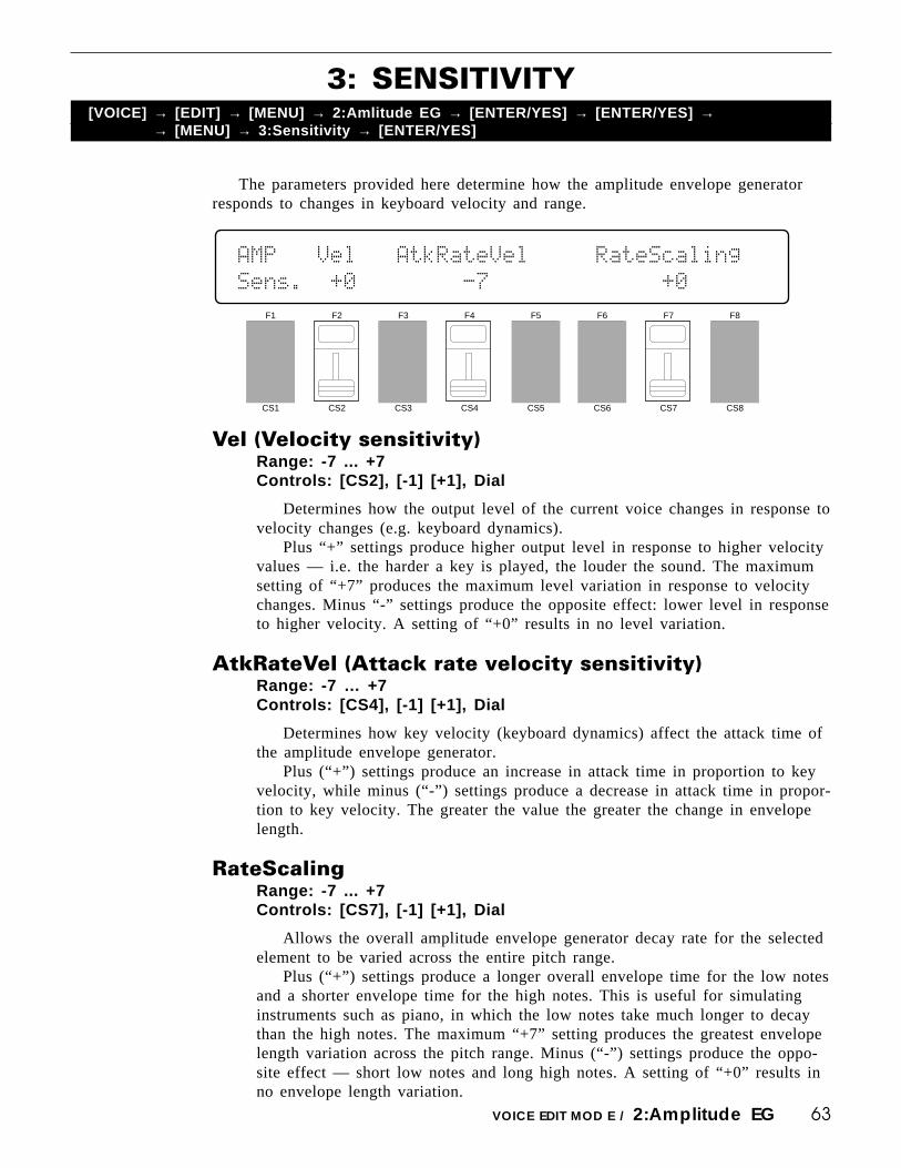
63
3: SENSITIVITY
The parameters provided here determine how the amplitude envelope generatorresponds to changes in keyboard velocity and range.
[VOICE] → [EDIT] → [MENU] → 2:Amlitude EG → [ENTER/YES] → [ENTER/YES] →→ [MENU] → 3:Sensitivity → [ENTER/YES]
VOICE EDIT MOD E / 2:Amplitude EG
F1
CS1
F2
CS2
F3
CS3
F4
CS4
F5
CS5
F6
CS6
F7
CS7
F8
CS8
AMP```Vel```AtkRateVel`````RateScaling``
Sens.``+0````````-7`````````````+0``````
Vel (Velocity sensitivity)Range: -7 ... +7Controls: [CS2], [-1] [+1], Dial
Determines how the output level of the current voice changes in response tovelocity changes (e.g. keyboard dynamics).
Plus “+” settings produce higher output level in response to higher velocityvalues — i.e. the harder a key is played, the louder the sound. The maximumsetting of “+7” produces the maximum level variation in response to velocitychanges. Minus “-” settings produce the opposite effect: lower level in responseto higher velocity. A setting of “+0” results in no level variation.
AtkRateVel (Attack rate velocity sensitivity)Range: -7 … +7Controls: [CS4], [-1] [+1], Dial
Determines how key velocity (keyboard dynamics) affect the attack time ofthe amplitude envelope generator.
Plus (“+”) settings produce an increase in attack time in proportion to keyvelocity, while minus (“-”) settings produce a decrease in attack time in propor-tion to key velocity. The greater the value the greater the change in envelopelength.
RateScalingRange: -7 ... +7Controls: [CS7], [-1] [+1], Dial
Allows the overall amplitude envelope generator decay rate for the selectedelement to be varied across the entire pitch range.
Plus (“+”) settings produce a longer overall envelope time for the low notesand a shorter envelope time for the high notes. This is useful for simulatinginstruments such as piano, in which the low notes take much longer to decaythan the high notes. The maximum “+7” setting produces the greatest envelopelength variation across the pitch range. Minus (“-”) settings produce the oppo-site effect — short low notes and long high notes. A setting of “+0” results inno envelope length variation.

64
AEG DATA COPY[VOICE] → [EDIT] → [MENU] → 2:Amplitude EG → [ENTER/YES] → [ENTER/YES] → [COPY]
This function facilitates voice editing by allowing the amplitude EG data fromany other voice (the “source” voice) to be copied to the current voice. You can copyan envelope that is close to the type you want, then edit it to produce the requiredsound.
VOICE EDIT MODE / 2:Amplitude EG
From VoiceRange: Any INTERNAL or CARD voiceControls: MEMORY, GROUP, PROGRAM, [CS5], [-1] [+1], Dial
Use the [INTERNAL 1], [INTERNAL 2], and [CARD] MEMORY keys toselect the memory area from which the source voice is to be selected. Use theGROUP keys to select the source voice bank, then use the PROGRAM keys toselect the source voice number. The [CS5] slider and other data entry controlscan also be used to select the source voice bank and number.
Once the source voice has been selected, press the [ENTER/YES] key. “Areyou sure?” will appear on the display.
AEG`COPY````````From`Voice``````````````
Are`you`sure`?```````¡A1:InitVce
Press the [ENTER/YES] key again to copy the AEG data, or press [EXIT/NO] to cancel the copy operation. Once the copy operation has finished, “Com-pleted!” will appear on the display briefly, then the display will return to theamplitude EG edit mode.
F1
CS1
F2
CS2
F3
CS3
F4
CS4
F5
CS5
F6
CS6
F7
CS7
F8
CS8
AEG`COPY````````From`Voice``````````````
`````````````````````¡A1:InitVce

65
1:TYPE, CUTOFF FREQUENCY[VOICE] → [EDIT] → [MENU] → 3:Filter → [ENTER/YES] → [ENTER/YES] →
→ [MENU] → 1:Cutoff Frequency → [ENTER/YES]
The SY85 features a sophisticated digital filter system that can be used to shapethe timbre of the voice being edited in a number of ways. Changes in the responseand cutoff frequency can be used to define the basic timbre of the voice, while EG-controlled filter sweeps can produce a virtually unlimited range of time-based timbrevariations.
VOICE EDIT MODE / 3:Filter
Cutoff Freq. (Cutoff frequency)Range: 0 … 127Controls: [CS4], [-1] [+1], Dial
Sets the cutoff frequency of the selected filter.Lower cutoff values produce a lower cutoff frequency and higher values
produce a higher cutoff frequency.
With an LPF response (selected by the “Type” parameter, below), a lowercutoff frequency reduces the range of high frequencies passed, making thesound “darker” or “rounder.”
With a HPF response, a higher cutoff frequency reduces the range of lowfrequencies passed, making the sound “thinner” or “sharper.”
F1
CS1
F2
CS2
F3
CS3
F4
CS4
F5
CS5
F6
CS6
F7
CS7
F8
CS8
FILTER`Cutoff`Freq.`Type`Band`Reso`CTRL`
`````(------Hz)`---`THRU``---```--``LFO`

66
Type (Filter type)Range: THRU, LPF, LPF12, HPF, BPF, BEFControls: [CS5], [-1] [+1], Dial
Determines the type of filter response used.The “THRU” (THROUGH) setting turns the filter OFF.
“LPF” and “LPF12” Types
The “LPF” (Low Pass Filter) and “LPF12” settings produces a filter re-sponse that allows only frequencies below the cutoff frequency (See “Cutoff”above) to pass. The “LPF” filter type has a steep 24-dB/octave cutoff slope,while the “LPF12” type has a gentler 12-dB/octave slope.
“HPF” Type
The “HPF” (High Pass Filter) setting produces a filter response that allowsonly frequencies above the cutoff frequency (See “Cutoff” above) to pass.
VOICE EDIT MODE / 3:Filter
67
“BPF” Type
The “BPF” (Band Pass Filter) setting produces a filter response that allowsonly a band of frequencies centered at the cutoff frequency (See “Cutoff”above) to pass. The “Band” parameter (below) determines the width of the passband.
VOICE EDIT MODE / 3:Filter
“BEF” Type
The “BEF” (Band Elimination Filter) setting produces a filter response thateliminates a band of frequencies centered at the cutoff frequency (See “Cutoff”above) to pass. The “Band” parameter (below) determines the width of theelimination band.
Band (BPF & BEF bandwidth)Range: 0 … 127Controls: [CS6], [-1] [+1], Dial
Determeines the width of the frequency pass or elimination band for theBPF and BEF filter types, respectively. The minimum setting of “0” producesan extremely narrow pass or elimination band, while the maximum setting of“127” produces a wide band.

68
Reso (Resonance)Range: 0 … 99Controls: [CS7], [-1] [+1], Dial
Determines the degree of filter resonance when the “LPF” filter type isselected (“--” appears in place of the resonance parameter when any other filtertype is selected).
This parameter has a similar effect to the “resonance” settings on traditionalanalog synthesizer filters — i.e. it determines the height of a peak in the filterresponse at the cutoff frequency.
VOICE EDIT MODE / 3:Filter
Higher resonance values produce a higher resonant peak and reduce theoverall bandwidth of the filter, passing a narrow band of frequencies at thefilter’s cutoff.
CTRL (Filter control)Range: EG, LFOControls: [CS8], [-1] [+1], Dial
Determines whether the cutoff frequency of the selected filter will be con-trolled by the LFO or by the filter envelope generator (EG).
Varying the filter cutoff frequency can create “sweep” or “wah-wah” typeeffects. If the cutoff is controlled via the LFO a cyclic variation based on the“shape” of the selected LFO waveform is produced. If EG control is selected,the filter envelope generator (see “FILTER EG LEVEL & RATE” below) canbe set up to produce a wide range of time-based variations.
Please note that if “LFO” is selected, the filter cutoff envelope generatorparameters have no effect on the sound.

69
2: CUTOFF SCALING[VOICE] → [EDIT] → [MENU] → 3:Filter → [ENTER/YES] → [ENTER/YES] →
→ [MENU] → 2:Cutoff Scaling → [ENTER/YES]
Cutoff scaling produces natural timbre variations across the range of the keyboardby allowing different filter cutoff frequency “offset” values to be applied to each offour “breakpoints” set at appropriate keys.
POINT 1 … 4Range: C-2 ... G8Controls: [CS1] … [CS4], [-1] [+1], Dial, [SHIFT] + Keyboard
Allows four separate cutoff envelope generator level-scaling breakpoints tobe set at any notes between C-2 and G8 for the selected filter.
To use the keyboard for breakpoint entry, simply select a breakpoint param-eter by pressing the coresponding function key or moving the correspondingcontinuous slider, then press the key at which you want to set the breakpointwhile holding the [SHIFT] key.
No breakpoint can be set to a key lower than the breakpoint to its left.
OFFSET 1 … 4Range: -127 ... +127Controls: [CS5] … [CS8], [-1] [+1], Dial
Sets the amount of level offset for each of the four level-scaling break-points set by the “Point” parameter described above.
Negative values lower the cutoff frequency, and positive values increase thecutoff frequency at the corresponding breakpoint. No matter what value ischosen, the cutoff frequency will never exceed its minimum or maximum value.When different offset values are applied to adjacent breakpoints, the cutofffrequency varies smoothly between the breakpoints.
VOICE EDIT MODE / 3:Filter
F1
CS1
F2
CS2
F3
CS3
F4
CS4
F5
CS5
F6
CS6
F7
CS7
F8
CS8
CUTOFF`SCALING``````)POINT1`(```````````
``C1```G2```E4```F4```+0```+0```+0```+0

70
3: FEG LEVEL & RATE[VOICE] → [EDIT] → [MENU] → 3:Filter → [ENTER/YES] → [ENTER/YES] →
→ [MENU] → 3:FEG Level&Rate → [ENTER/YES]
The filter envelope generator is entirely separate from the amplitude EG, and isused specifically to create time-based timbre variations. It can be used to simulate thenatural timbre variations produced by acoustic instruments, or to create more pro-nounced electronic effects.
LVL/RATE (Level/Rate switch)Range: LVL, RATEControls: [F1]
This “switch” determines whether the level parameters (L0 … L4, RL1, andRL2) or the rate parameters (RS, R1 … R4, RR1, and RR2), described below,are selected for editing.
L0 … L4, RL1, RL2 (Levels 0 … 4, Release levels 1 & 2)Range: -63 ... +63Controls: [CS2] … [CS8], [-1] [+1], Dial
These parameters are available when the Level/Rate switch parameter is setto “LVL”.
The level parameters work in conjunction with the rate parameters describedbelow to determine the “shape” of the cutoff envelope generator for the se-lected filter. This function is only available if the “CTRL” parameter (page 68)is set to “EG.”
The cutoff envelope generator level parameters correspond to cutoff fre-quency. Plus “+” values produce higher cutoff frequencies while minus “-”
VOICE EDIT MODE / 3:Filter
F1
CS1
F2
CS2
F3
CS3
F4
CS4
F5
CS5
F6
CS6
F7
CS7
F8
CS8
FEG````L0`π`L1`π`L2```L3`π`L4`πRL1`πRL2π[LVL]``+0```+0``-63`ƒ`+0```+0```+0```+0
F1
CS1
F2
CS2
F3
CS3
F4
CS4
F5
CS5
F6
CS6
F7
CS7
F8
CS8
FEG````RS`π`R1`π`R2```R3`π`R4`πRR1`πRR2π[RATE]`+0````0````0`ƒ``0````0````0````0`

71
values produce lower cutoff frequencies. “0” level values produce the normalcutoff frequency as determined by the cutoff parameter (See “Cutoff” on page65).
RS (Rate scaling)Range: -7 ... +7Controls: [CS2], [-1] [+1], Dial
Allows the overall cutoff envelope generator rate for the selected filter tobe varied across the entire pitch range (i.e. keyboard range). This function isonly available if the “CTRL” parameter (page 68) is set to “EG.”
Plus (“+”) settings produce a longer overall envelope time for the low notesand a shorter envelope time for the high notes. The maximum “+7” settingproduces the greatest envelope length variation across the pitch range. Minus(“-”) settings produce the opposite effect — a shorter low-note envelope andlonger high-note envelope. A setting of “+0” results in no envelope lengthvariation.
R1 … R4, RR1, RR2 (Rates 1 … 4, Release rates 1 & 2)Range: 0 … 63Controls: [CS3] … [CS8], [-1] [+1], Dial
These parameters work in conjunction with the level parameters describedabove to determine the “shape” of the cutoff envelope generator for the se-lected filter. This function is only available if the “CTRL” parameter (page 68)is set to “EG.”
The “Rate” parameters work in the same way as the amplitude and pitchenvelope generator rate parameters: a setting of “63” produces the fastest (al-most instantaneous) rate between levels, while the minimum setting of “0”produces the slowest change.
The filter envelope begins at L0 (Level 0), moves to L1 (Level 1) at a ratedetermined by the setting of R1, then to L2 (Level 2) at R2 (Rate 2), then toL3 (Level 3) at R3 (Rate 3), and then to L4 (Level 4) at R4 (Rate 4). Thecutoff stays at L4 until the key is released, and then moves to RL1 (ReleaseLevel 1) at the rate determined by RR1 (Release Rate 1), and finally to RL2(Release Level 2) at RR2 (Release Rate 2).
VOICE EDIT MODE / 3:Filter

72
4: FILTER SENSITIVITY
These parameters determine how the filter envelope generator is affected bykeyboard dynamics.
Type (Velocity sensitivity type)Range: EG_attack, EG_shiftControls: [CS4], [-1] [+1], Dial
Determines whether changes in key velocity (keyboard dynamics) affect theattack level of the filter EG or its cutoff frequency. When set to “EG_attack”,velocity affects filter EG attack level, and when set to “EG_shift”, velocityaffects the filter cutoff frequency.
Vel (Velocity sensitivity)Range: -63 ... +63Controls: [CS5], [-1] [+1], Dial
Determines how the filter cutoff frequency changes in response to velocitychanges (e.g. keyboard dynamics).
Plus “+” settings produce higher cutoff frequencies in response to highervelocity values — i.e. the harder a key is played, the higher the cutoff fre-quency. The maximum setting of “+63” produces the maximum level variationin response to velocity changes. Minus “-” settings produce the opposite effect:lower cutoff in response to higher velocity. A setting of “+0” results in nocutoff variation.
AtkRateVel (Attack rate velocity sensitivity)Range: -63 ... +63Controls: [CS8], [-1] [+1], Dial
Determines how key velocity (keyboard dynamics) affect the attack portionof the filter EG envelope.
Plus (“+”) settings produce an increase in attack time in proportion to keyvelocity, while minus (“-”) settings produce a decrease in attack time in propor-tion to key velocity. The greater the value the greater the change in attacktime.
[VOICE] → [EDIT] → [MENU] → 3:Filter → [ENTER/YES] → [ENTER/YES] →→ [MENU] → 4:Filter Sensitivity → [ENTER/YES]
VOICE EDIT MODE / 3:Filter
F1
CS1
F2
CS2
F3
CS3
F4
CS4
F5
CS5
F6
CS6
F7
CS7
F8
CS8
FILTER`SENS.```Type``Vel`````AtkRateVel`
```````````EG»attack``+0`````````````+0`

73
FILTER DATA COPY[VOICE] → [EDIT] → [MENU] → 3:Filter → [ENTER/YES] → [ENTER/YES]→ [COPY]
This function facilitates voice editing by allowing the filter parameters from anyother voice (the “source” voice) to be copied to the current voice. You can copy afilter setup that is close to the type you want, then edit it to produce the requiredsound.
VOICE EDIT MODE / 3:Filter
From VoiceRange: Any INTERNAL or CARD voiceControls: MEMORY, GROUP, PROGRAM, [CS5], [-1] [+1], Dial
Use the [INTERNAL 1], [INTERNAL 2], and [CARD] MEMORY keys toselect the memory area from which the source voice is to be selected. Use theGROUP keys to select the source voice bank, then use the PROGRAM keys toselect the source voice number. The [CS5] slider and other data entry controlscan also be used to select the source voice number.
Once the source voice has been selected, press the [ENTER/YES] key. “Areyou sure?” will appear on the display.
FILTER`COPY`````From`Voice``````````````
Are`you`sure`?```````¡A1:InitVce
Press the [ENTER/YES] key again to copy the filter data, or press [EXIT/NO] to cancel the copy operation. Once the copy operation has finished, “Com-pleted!” will appear on the display briefly, then the display will return to thefilter edit mode.
F1
CS1
F2
CS2
F3
CS3
F4
CS4
F5
CS5
F6
CS6
F7
CS7
F8
CS8
FILTER`COPY`````From`Voice``````````````
`````````````````````¡A1:InitVce
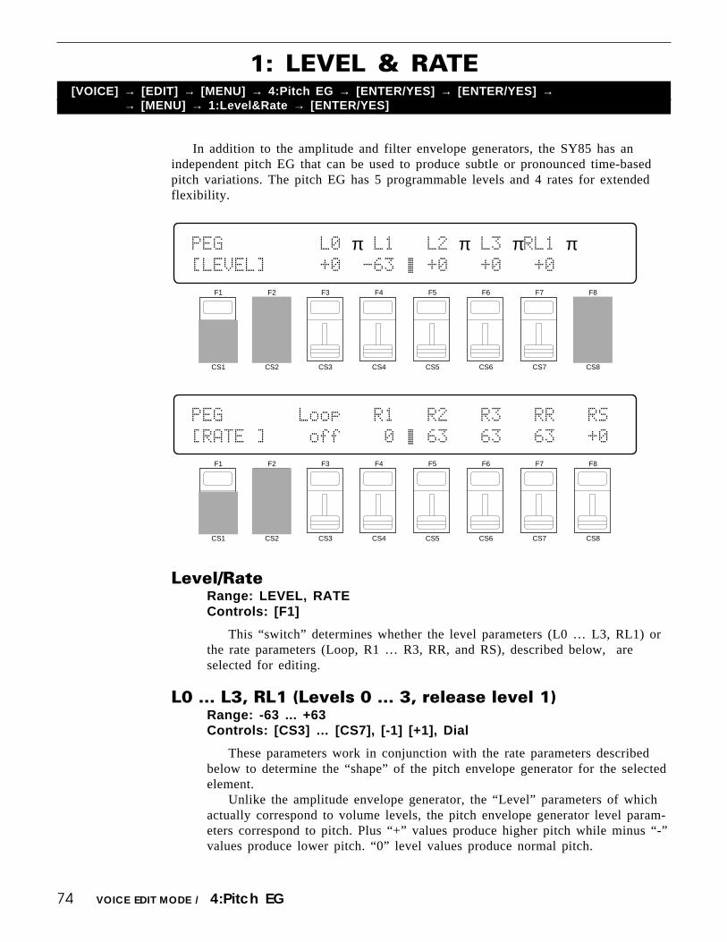
74
1: LEVEL & RATE[VOICE] → [EDIT] → [MENU] → 4:Pitch EG → [ENTER/YES] → [ENTER/YES] →
→ [MENU] → 1:Level&Rate → [ENTER/YES]
In addition to the amplitude and filter envelope generators, the SY85 has anindependent pitch EG that can be used to produce subtle or pronounced time-basedpitch variations. The pitch EG has 5 programmable levels and 4 rates for extendedflexibility.
VOICE EDIT MODE / 4:Pitch EG
Level/RateRange: LEVEL, RATEControls: [F1]
This “switch” determines whether the level parameters (L0 … L3, RL1) orthe rate parameters (Loop, R1 … R3, RR, and RS), described below, areselected for editing.
L0 … L3, RL1 (Levels 0 … 3, release level 1)Range: -63 ... +63Controls: [CS3] … [CS7], [-1] [+1], Dial
These parameters work in conjunction with the rate parameters describedbelow to determine the “shape” of the pitch envelope generator for the selectedelement.
Unlike the amplitude envelope generator, the “Level” parameters of whichactually correspond to volume levels, the pitch envelope generator level param-eters correspond to pitch. Plus “+” values produce higher pitch while minus “-”values produce lower pitch. “0” level values produce normal pitch.
F1
CS1
F2
CS2
F3
CS3
F4
CS4
F5
CS5
F6
CS6
F7
CS7
F8
CS8
PEG`````````L0`π`L1```L2`π`L3`πRL1`π````[LEVEL]`````+0``-63`ƒ`+0```+0```+0``````
F1
CS1
F2
CS2
F3
CS3
F4
CS4
F5
CS5
F6
CS6
F7
CS7
F8
CS8
PEG```````Loop`π`R1```R2`π`R3`π`RR`π`RS`[RATE`]````off````0`ƒ`63```63```63```+0`

75
LoopRange: off, onControls: [CS3], [-1] [+1], Dial
When the Loop parameter is set to “on” the pitch EG cycle repeats fromthe beginning (L0) to the L3 level until the keys being played are released.When set to “off,” the L3 level is maintained until the keys being played arereleased.
R1 … R3, RR (Rates 1 … 3, release rate)Range: 0 ... +63Controls: [CS4] … [CS7], [-1] [+1], Dial
These parameters work in conjunction with the level parameters describedabove to determine the “shape” of the pitch envelope generator for the selectedelement.
The “Rate” parameters work in the same way as the amplitude envelopegenerator rate parameters: a setting of “63” produces the fastest (almost instan-taneous) rate between levels, while the minimum setting of “0” produces theslowest change.
The pitch envelope begins at L0 (Level 0), moves to L1 (Level 1) at a ratedetermined by the setting of R1, then to L2 (Level 2) at R2 (Rate 2), and thento L3 (Level 3) at R3 (Rate 3). The pitch stays at L3 until the key is released,and then moves to RL1 (Release Level 1) at the rate determined by RR (Re-lease Rate).
VOICE EDIT MODE / 4:Pitch EG
RS (Pitch EG rate scaling)Range: -7 … +7Controls: [CS8], [-1] [+1], Dial
Allows the overall pitch envelope generator rate for the selected element tobe varied across the entire pitch range.
Plus (“+”) settings produce a longer overall envelope time for the low notesand a shorter envelope time for the high notes. The maximum “+7” settingproduces the greatest envelope length variation across the pitch range. Minus(“-”) settings produce the opposite effect — a shorter low-note envelope andlonger high-note envelope. A setting of “+0” results in no envelope lengthvariation.

76
2: RANGE, SENSITIVITY
These parameters determined the overall range of the pitch EG, and how it isaffected by variations in keyboard velocity.
RangeRange: 1/8oct, 1/2oct, 1oct, 2octControls: [CS3], [-1] [+1], Dial
Sets the maximum range of pitch envelope generator pitch variation.This parameter determines the total maximum range of the pitch envelope
generator, so a setting of “2oct” means that the maximum range is ±1 octave.That is, if a level parameter is set to +63, for example, the pitch at that pointwill be one octave above normal pitch.
Vel (Pitch EG velocity sensitivity)Range: -7 … +7Controls: [CS5], [-1] [+1], Dial
Determines how the overall envelope depth of the pitch envelope generatoris controlled by velocity information.
Plus (“+”) values produce a deeper pitch envelope in response to highervelocity, while minus (“-”) values produce a shallower pitch envelope in re-sponse to higher velocity values. The greater the value the greater the changein pitch envelope depth.
RateVel (Pitch EG rate velocity sensitivity)Range: -7 … +7Controls: [CS6], [-1] [+1], Dial
Determines how the overall envelope length of the pitch envelope generatoris controlled by velocity information.
Plus (“+”) values produce a longer pitch envelope in response to highervelocity, while minus (“-”) values produce a shorter pitch envelope in responseto higher velocity values. The greater the value the greater the change in pitchenvelope length.
[VOICE] → [EDIT] → [MENU] → 4:Pitch EG → [ENTER/YES] → [ENTER/YES] →→ [MENU] → 2:Sensitivity → [ENTER/YES]
VOICE EDIT MODE / 4:Pitch EG
F1
CS1
F2
CS2
F3
CS3
F4
CS4
F5
CS5
F6
CS6
F7
CS7
F8
CS8
PEG`SENS.``Range`````Vel`RateVel````````
`````````````1oct`````+0```+0``````
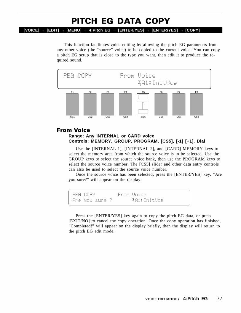
77
This function facilitates voice editing by allowing the pitch EG parameters fromany other voice (the “source” voice) to be copied to the current voice. You can copya pitch EG setup that is close to the type you want, then edit it to produce the re-quired sound.
PITCH EG DATA COPY[VOICE] → [EDIT] → [MENU] → 4:Pitch EG → [ENTER/YES] → [ENTER/YES] → [COPY]
VOICE EDIT MODE / 4:Pitch EG
From VoiceRange: Any INTERNAL or CARD voiceControls: MEMORY, GROUP, PROGRAM, [CS5], [-1] [+1], Dial
Use the [INTERNAL 1], [INTERNAL 2], and [CARD] MEMORY keys toselect the memory area from which the source voice is to be selected. Use theGROUP keys to select the source voice bank, then use the PROGRAM keys toselect the source voice number. The [CS5] slider and other data entry controlscan also be used to select the source voice number.
Once the source voice has been selected, press the [ENTER/YES] key. “Areyou sure?” will appear on the display.
PEG`COPY````````From`Voice``````````````
Are`you`sure`?```````¡A1:InitVce
Press the [ENTER/YES] key again to copy the pitch EG data, or press[EXIT/NO] to cancel the copy operation. Once the copy operation has finished,“Completed!” will appear on the display briefly, then the display will return tothe pitch EG edit mode.
F1
CS1
F2
CS2
F3
CS3
F4
CS4
F5
CS5
F6
CS6
F7
CS7
F8
CS8
PEG`COPY````````From`Voice``````````````
`````````````````````¡A1:InitVce

78
1: LFO
These parameters define the operation of the SY85’s main LFO (Low FrequencyOscillator). The main LFO controls amplitude, pitch, frequency, and filter cutoffmodulation applied via the modulation wheel, the foot controller, and keyboardaftertouch response.
[VOICE] → [EDIT] → [MENU] → 5:LFO → [ENTER/YES] → [ENTER/YES] →→ [MENU] → 1:LFO → [ENTER/YES]
VOICE EDIT MODE / 5:LFO
Wave (LFO waveform)Range: tri, dwn, up, squ, sin, S/HControls: [CS2], [-1] [+1], Dial
Determines the waveform of the LFO.
“tri” = Triangle. “dwn” = Downward sawtooth.“up” = Upward sawtooth. “squ” = Square.“sin” = Sine. “S/H” = Sample and hold.
Sped (LFO speed)Range: 0 … 99Controls: [CS3], [-1] [+1], Dial
Sets the speed of the LFO.“0” is the slowest Speed setting, producing an LFO speed of approximately
0 Hertz. The fastest setting of 99 produces an LFO speed of approximately 25Hertz.
Pmod (Pitch modulation depth)Range: 0 … 127Controls: [CS4], [-1] [+1], Dial
Sets the maximum amount of pitch modulation that can be applied to thecurrent voice.
A “0” setting produces no modulation while a setting of “127” producesmaximum modulation. Pitch modulation produces a periodic pitch variation,thereby creating a vibrato effect.
Please note that the pitch modulation depth parameter for the controllerwhich is to be used to apply pitch modulation (see page 83, 85, and 87) mustalso be set to an appropriate value before pitch modulation can be applied.
F1
CS1
F2
CS2
F3
CS3
F4
CS4
F5
CS5
F6
CS6
F7
CS7
F8
CS8
LFO``Wave`Sped`Pmod`Amod`Fmod`Dely`Phase
`∆˚∆``tri```64````0````0````0````0````0±

79
Amod (Amplitude modulation depth)Range: 0 … 127Controls: [CS5], [-1] [+1], Dial
Sets the maximum amount of amplitude modulation that can be applied tothe current voice.
A “0” setting produces no modulation while a setting of “127” producesmaximum modulation. Amplitude modulation produces a periodic variation inthe volume of the sound, thus creating a tremolo effect.
Please note that the amplitude modulation depth parameter for the controllerwhich is to be used to apply amplitude modulation (see page 83, 85, and 87)must also be set to an appropriate value before amplitude modulation can beapplied.
Fmod (Filter cutoff frequency modulation depth)Range: 0 … 127Controls: [CS6], [-1] [+1], Dial
Sets the maximum amount of filter cuttoff modulation that can be appliedto the current voice.
A “0” setting produces no modulation while a setting of “127” producesmaximum modulation. Filter cutoff modulation produces wah-wah type effects.
Please note that the filter cutoff modulation depth parameter for the control-ler which is to be used to apply cutoff modulation (see page 84, 86, and 88)must also be set to an appropriate value before cutoff frequency modulation canbe applied.
Dely (Delay)Range: 0 … 99Controls: [CS7], [-1] [+1], Dial
Sets the delay time between the beginning of a note and the beginning ofLFO operation for the selected element.
The minimum setting “0” results in no delay, while the maximum setting of“99” produces a delay of approximately 2.66 seconds before the LFO beginsoperation (5.3 seconds before it reaches maximum depth).
PhaseRange: 0 … 180Controls: [CS8], [-1] [+1], Dial
Determines at which point in the LFO waveform the LFO will begin opera-tion for the selected element. The values 0 through 180 correspond to phaseangles in degrees. The illustration below shows how the various phase anglescorrespond to points on the LFO waveform (a sine wave is used for clarity).
VOICE EDIT MODE / 5:LFO

80
2: LFO SPEED SENSITIVITY
The speed of the SY85 LFO can be varied randomly, and according to variationsin keyboard velocity and range. Such variations can produce more natural, musicaleffects.
[VOICE] → [EDIT] → [MENU] → 5:LFO → [ENTER/YES] → [ENTER/YES] →→ [MENU] → 2:LFO Speed Sensitivity → [ENTER/YES]
VOICE EDIT MODE / 5:LFO
RandomRange: 0 … 7Controls: [CS4], [-1] [+1], Dial
Sets the amount of random LFO speed variation produced each time a noteis played.
When this parameter is set to a value other than “0,” the LFO speedchanges randomly each time a note is played. A setting of “7” produces thegreatest amount of random speed change.
VelocityRange: -7 … +7Controls: [CS6], [-1] [+1], Dial
Determines how the LFO speed changes in response to velocity changes(e.g. keyboard dynamics).
Plus “+” settings produce higher LFO speed in response to higher velocityvalues — i.e. the harder a key is played, the higher the LFO speed. The maxi-mum setting of “+7” produces the maximum speed variation in response tovelocity changes. Minus “-” settings produce the opposite effect: lower speed inresponse to higher velocity. A setting of “+0” results in no speed variation.
KeyScaleRange: -7 … +7Controls: [CS8], [-1] [+1], Dial
Determines how the LFO speed changes in response to the key played.Plus “+” settings produce higher LFO speed when higher notes on the
keyboard are played. The maximum setting of “+7” produces the maximumspeed variation. Minus “-” settings produce the opposite effect: lower speedwhen higher notes are played. A setting of “+0” results in no speed variation.
F1
CS1
F2
CS2
F3
CS3
F4
CS4
F5
CS5
F6
CS6
F7
CS7
F8
CS8
LFO`SPEED`SENS.`Random`Velocity`KeyScale
``````````````````0````````+0````````+0`

81
This function facilitates voice editing by allowing the LFO parameters from anyother voice (the “source” voice) to be copied to the current voice. You can copy anLFO setup that is close to the type you want, then edit it to produce the requiredsound.
LFO DATA COPY[VOICE] → [EDIT] → [MENU] → 5:LFO → [ENTER/YES] → [ENTER/YES] → [COPY]
VOICE EDIT MODE / 5:LFO
From VoiceRange: Any INTERNAL or CARD voiceControls: MEMORY, GROUP, PROGRAM, [CS5], [-1] [+1], Dial
Use the [INTERNAL 1], [INTERNAL 2], and [CARD] MEMORY keys toselect the memory area from which the source voice is to be selected. Use theGROUP keys to select the source voice bank, then use the PROGRAM keys toselect the source voice number. The [CS5] slider and other data entry controlscan also be used to select the source voice number.
Once the source voice has been selected, press the [ENTER/YES] key. “Areyou sure?” will appear on the display.
LFO`COPY````````From`Voice``````````````
Are`you`sure`?```````¡A1:InitVce
Press the [ENTER/YES] key again to copy the LFO data, or press [EXIT/NO] to cancel the copy operation. Once the copy operation has finished, “Com-pleted!” will appear on the display briefly, then the display will return to theLFO edit mode.
F1
CS1
F2
CS2
F3
CS3
F4
CS4
F5
CS5
F6
CS6
F7
CS7
F8
CS8
LFO`COPY````````From`Voice``````````````
`````````````````````¡A1:InitVce

82
1: PITCH BEND RANGE[VOICE] → [EDIT] → [MENU] → 6:Controller → [ENTER/YES] → [ENTER/YES] →
→ [MENU] → 1:Pitch Bend Range → [ENTER/YES]
This screen includes parameters that set the SY85’s pitch bend range, the mini-mum volume attainable with the foot volume controller, and the sustain switch en-able/disable mode.
VOICE EDIT MODE / 6:Controller
PB Range (Pitch bend range)Range: 0 … 12Controls: [CS3], [-1] [+1], Dial
Sets the maximum pitch bend range.Each increment from “0” to “12” represents a semitone. A setting of “0”
produces no pitch bend. A setting of “12” allows a maximum pitch bend ofplus or minus one octave, while a setting of “4” allows a maximum pitch bendof plus or minus a major third.
VolLoLimit (Minimum foot volume level)Range: 0 … 127Controls: [CS5], [-1] [+1], Dial
Determines the minimum volume level that can be set by the foot volumecontrol. If this parameter is set to “0,” the minimum foot volume control posi-tion will produce no sound. A setting of “63” will result in about half volumewhen the control is set to its minimum position.
SustainSw (Sustain switch enable)Range: enable, disableControls: [CS7], [-1] [+1], Dial
Enables or disables sustain footswitch operation. The sustain footswitchoperates normally when this parameter is set to “enable,” but has no effectwhen set to “disable.”
F1
CS1
F2
CS2
F3
CS3
F4
CS4
F5
CS5
F6
CS6
F7
CS7
F8
CS8
CTRL`````PB»Range`VolLowLimit``SustainSw
`````````````2`````````0````````enable``

83
2: MODULATION WHEEL DEPTH[VOICE] → [EDIT] → [MENU] → 6:Controller → [ENTER/YES] → [ENTER/YES] →
→ [MENU] → 2:MW Depth → [ENTER/YES]
The modulation wheel can be used to control a wide range of modulation effects.The parameters provided in this screen set the depth of each effect type.
Amod (Amplitude modulation depth)Range: 0 … 127Controls: [CS4], [-1] [+1], Dial
Sets the maximum depth of amplitude modulation (tremolo effects) appliedvia the modulation wheel.
A setting of “0” allows no amplitude modulation, while a setting of 127results in maximum amplitude modulation depth.
When setting up the low-frequency oscillator to apply amplitude modula-tion, this parameter must be set to a value other than “0” if amplitude modula-tion is to be applied via the modulation wheel.
Pmod (Pitch modulation depth)Range: 0 … 127Controls: [CS5], [-1] [+1], Dial
Sets the maximum depth of pitch modulation (vibrato effects) applied viathe modulation wheel.
A setting of “0” allows no pitch modulation, while a setting of 127 resultsin maximum amplitude modulation.
When setting up the low-frequency oscillator to apply pitch modulation, thisparameter must be set to a value other than “0” if pitch modulation is to beapplied via the modulation wheel.
VOICE EDIT MODE / 6:Controller
F1
CS1
F2
CS2
F3
CS3
F4
CS4
F5
CS5
F6
CS6
F7
CS7
F8
CS8
CTRL`MW````````Amod`Pmod`Fmod`EGBs`Coff`
``````````````````0````0````0```+0```+0`

84
Fmod (Frequency modulation depth)Range: 0 … 127Controls: [CS6], [-1] [+1], Dial
Sets the maximum depth of filter cutoff frequency modulation (wah-wahtype effects) applied via the modulation wheel.
A setting of “0” allows no frequency modulation, while a setting of 127results in maximum frequency modulation.
When setting up the LFO (low-frequency oscillator) to apply cutoff modula-tion, this parameter must be set to a value other than “0” if cutoff modulationis to be applied via the modulation wheel. Also, the filter “CTRL” parameter(page 68) must be set to “LFO” in order to vary the cutoff frequency continu-ously.
EGBs (EG bias depth)Range: -127 … +127Controls: [CS7], [-1] [+1], Dial
Sets the depth and “direction” of EG bias produced by the modulationwheel. EG bias increases or decreases the amplitude envelope generator levels,simulating the dynamic variations that can be produced on an acoustic instru-ment more accurately than simple volume control.
A setting of “0” produces no change in EG levels. Plus (“+”) settingsproduce an increase in level when the modulation wheel is rolled upward, andminus (“-”) settings produce a decrease in level when when the modultionwheel is rolled upward. The greater the value, the greater the change in level.
Coff (Cutoff frequency depth)Range: -127 … +127Controls: [CS8], [-1] [+1], Dial
Sets the maximum depth of filter cutoff frequency variation applied via themodulation wheel.
Plus “+” settings produce higher cutoff frequencies in response to modula-tion wheel operation — i.e. the higher the modulation wheel position, thehigher the cutoff frequency. The maximum setting of “+127” produces themaximum cutoff variation. Minus “-” settings produce the opposite effect: lowercutoff in response to higher modulation wheel positions. A setting of “+0”results in no cutoff variation. The filter “CTRL” parameter (page 68) must beset to “LFO” in order to vary the cutoff frequency continuously.
VOICE EDIT MODE / 6:Controller

85
3: FOOT CONTROLLER DEPTH
The SY85 allows modulation control via a foot controller connected to th rear-panel FOOT CONTROLLER jack as well as the modulation wheel. This allowsmodulation effects to be applied while playing with both hands. The parameters inthis screen set the depth of the foot controller modulation effects.
Amod (Amplitude modulation depth)Range: 0 … 127Controls: [CS4], [-1] [+1], Dial
Sets the maximum depth of amplitude modulation (tremolo effects) appliedvia the foot controller.
A setting of “0” allows no amplitude modulation, while a setting of 127results in maximum amplitude modulation depth.
When setting up the low-frequency oscillator to apply amplitude modula-tion, this parameter must be set to a value other than “0” if amplitude modula-tion is to be applied via the foot controller.
Pmod (Pitch modulation depth)Range: 0 … 127Controls: [CS5], [-1] [+1], Dial
Sets the maximum depth of pitch modulation (vibrato effects) applied viathe foot controller.
A setting of “0” allows no pitch modulation, while a setting of 127 resultsin maximum amplitude modulation.
When setting up the low-frequency oscillator to apply pitch modulation, thisparameter must be set to a value other than “0” if pitch modulation is to beapplied via the foot controller.
[VOICE] → [EDIT] → [MENU] → 6:Controller → [ENTER/YES] → [ENTER/YES] →→ [MENU] → 3:FC Depth → [ENTER/YES]
VOICE EDIT MODE / 6:Controller
F1
CS1
F2
CS2
F3
CS3
F4
CS4
F5
CS5
F6
CS6
F7
CS7
F8
CS8
CTRL`FC````````Amod`Pmod`Fmod`EGBs`Coff`
``````````````````0````0````0```+0```+0`

86
Fmod (Frequency modulation depth)Range: 0 … 127Controls: [CS6], [-1] [+1], Dial
Sets the maximum depth of filter cutoff frequency modulation (wah-wahtype effects) applied via the foot controller.
A setting of “0” allows no frequency modulation, while a setting of 127results in maximum frequency modulation.
When setting up the LFO (low-frequency oscillator) to apply cutoff modula-tion, this parameter must be set to a value other than “0” if cutoff modulationis to be applied via the foot controller. Also, the filter “CTRL” parameter (page68) must be set to “LFO” in order to vary the cutoff frequency continuously.
EGBs (EG bias depth)Range: -127 … +127Controls: [CS7], [-1] [+1], Dial
Sets the depth and “direction” of EG bias produced by the foot controller.EG bias increases or decreases the amplitude envelope generator levels, simu-lating the dynamic variations that can be produced on an acoustic instrumentmore accurately than simple volume control.
A setting of “0” produces no change in EG levels. Plus (“+”) settingsproduce an increase in level when the foot controller is applied, and minus (“-”) settings produce a decrease in level when the foot controller is applied. Thegreater the value, the greater the change in level.
Coff (Cutoff frequency depth)Range: -127 … +127Controls: [CS8], [-1] [+1], Dial
Sets the maximum depth of filter cutoff frequency variation applied via thefoot controller.
Plus “+” settings produce higher cutoff frequencies in response to footcontroller operation — i.e. the more the foot controller is depressed, the higherthe cutoff frequency. The maximum setting of “+127” produces the maximumcutoff variation. Minus “-” settings produce the opposite effect: lower cutoff inresponse to higher foot controller positions. A setting of “+0” results in nocutoff variation. The filter “CTRL” parameter (page 68) must be set to “LFO”in order to vary the cutoff frequency continuously.
VOICE EDIT MODE / 6:Controller

87
4: AFTER TOUCH DEPTH[VOICE] → [EDIT] → [MENU] → 6:Controller → [ENTER/YES] → [ENTER/YES] →
→ [MENU] → 4:AT Depth → [ENTER/YES]
For truly “intimate” modulation control, the SY85 allows a number of modulationeffects to be controlled via keyboard aftertouch response. The parameters in thisscreen set the depth of the aftertouch modulation effects.
Amod (Amplitude modulation depth)Range: 0 … 127Controls: [CS3], [-1] [+1], Dial
Sets the maximum depth of amplitude modulation (tremolo effects) appliedvia keyboard aftertouch.
A setting of “0” allows no amplitude modulation, while a setting of 127results in maximum amplitude modulation depth.
When setting up the low-frequency oscillator to apply amplitude modula-tion, this parameter must be set to a value other than “0” if amplitude modula-tion is to be applied via keyboard after touch.
Pmod (Pitch modulation depth)Range: 0 … 127Controls: [CS4], [-1] [+1], Dial
Sets the maximum depth of pitch modulation (vibrato effects) applied viakeyboard aftertouch.
A setting of “0” allows no pitch modulation, while a setting of 127 resultsin maximum amplitude modulation.
When setting up the low-frequency oscillator to apply pitch modulation, thisparameter must be set to a value other than “0” if pitch modulation is to beapplied via keyboard aftertouch.
VOICE EDIT MODE / 6:Controller
F1
CS1
F2
CS2
F3
CS3
F4
CS4
F5
CS5
F6
CS6
F7
CS7
F8
CS8
CTRL`AT````Amod`Pmod`Fmod`EGBs`Coff`PtBs
``````````````0````0````0```+0```+0```+0

88
Fmod (Frequency modulation depth)Range: 0 … 127Controls: [CS5], [-1] [+1], Dial
Sets the maximum depth of filter cutoff frequency modulation (wah-wahtype effects) applied via keyboard aftertouch.
A setting of “0” allows no frequency modulation, while a setting of 127results in maximum frequency modulation.
When setting up the LFO (low-frequency oscillator) to apply cutoff modula-tion, this parameter must be set to a value other than “0” if cutoff modulationis to be applied via keyboard aftertouch. Also, the filter “CTRL” parameter(page 68) must be set to “LFO” in order to vary the cutoff frequency continu-ously.
EGBs (EG bias depth)Range: -127 … +127Controls: [CS6], [-1] [+1], Dial
Sets the depth and “direction” of EG bias produced by aftertouch response.EG bias increases or decreases the amplitude envelope generator levels, simu-lating the dynamic variations that can be produced on an acoustic instrumentmore accurately than simple volume control.
A setting of “0” produces no change in EG levels. Plus (“+”) settingsproduce an increase in level when aftertouch is applied, and minus (“-”) set-tings produce a decrease in level when aftertouch is applied. The greater thevalue, the greater the change in level.
Coff (Cutoff frequency depth)Range: -127 … +127Controls: [CS7], [-1] [+1], Dial
Sets the maximum depth of filter cutoff frequency variation applied viakeyboard aftertouch.
Plus “+” settings produce higher cutoff frequencies in response to aftertouch— i.e. the greater the aftertouch pressure, the higher the cutoff frequency. Themaximum setting of “+127” produces the maximum cutoff variation. Minus “-”settings produce the opposite effect: lower cutoff in response to greateraftertouch pressure. A setting of “+0” results in no cutoff variation. The filter“CTRL” parameter (page 68) must be set to “LFO” in order to vary the cutofffrequency continuously.
PtBs (Pitch bias depth)Range: -12 … +12Controls: [CS8], [-1] [+1], Dial
Sets the maximum pitch variation range achievable via after-touch control.Each increment represents a semitone. A setting of “0” produces no pitch
variation. A setting of “+12” allows a maximum pitch variation of one octaveup, while a setting of “-12” allows a maximum pitch variation of one octavedown corresponding to aftertouch key pressure.
VOICE EDIT MODE / 6:Controller

89
5: CS3 PARAMETER EDIT
The [CS3] and [CS4] sliders can be assigned to control a wide range of voiceparameters in real time while playing the SY85. These parameters assign a voiceparameter to the [CS3] slider, and set the maximum and minimum limits of thecontrol range.
[VOICE] → [EDIT] → [MENU] → 6:Controller → [ENTER/YES] → [ENTER/YES] →→ [MENU] → 5:CS3 Parameter → [ENTER/YES]
VOICE EDIT MODE / 6:Controller
CS3 Param (CS3 parameter)Range: 0 … 75Controls: [CS1], [-1] [+1], Dial
Assigns any of 75 different voice parameters to be controlled via the [CS3]slider.
The numbers and abbreviations associated with each voice parameter arelisted below:
F1
CS1
F2
CS2
F3
CS3
F4
CS4
F5
CS5
F6
CS6
F7
CS7
F8
CS8
CTRL`CS3`Param(CTRL#=18)``Min.``````Max.
```0:No»Assign``````````````0%``````100%
CS3 PARAMETER LIST (0 … 39)
0: “No_Assign ”1: “CT_MW_Pmod”2: “CT_MW_Amod”3: “CT_MW_Fmod”4: “CT_MW_Coff”5: “CT_MW_EGBs”6: “CT_FC_Pmod”7: “CT_FC_Amod”8: “CT_FC_Fmod”9: “CT_FC_Coff”10: “CT_FC_EGBs”11: “CT_AT_Pmod”12: “CT_AT_Amod”13: “CT_AT_Fmod”14: “CT_AT_Coff”15: “CT_AT_EGBs”16: “CT_AT_PtBs”17: “CT_PBRange”18: “CT_VLLoLim”19: “TotalLevel”
20: “EF_SendLvl”21: “OS_FrqFine”22: “OS_Random ”23: “PEG_Rate1 ”24: “PEG_Rate2 ”25: “PEG_Rate3 ”26: “PEG_RlsRt ”27: “PEG_Level0”28: “PEG_Level1”29: “PEG_Level2”30: “PEG_Level3”31: “PEG_RlsLvl”32: “PEG_Range ”33: “PEG_LvlVel”34: “PEG_RtVel ”35: “LFO_Speed ”36: “LFO_Delay ”37: “LFO_Pmod ”38: “LFO_Amod ”39: “LFO_Fmod ”
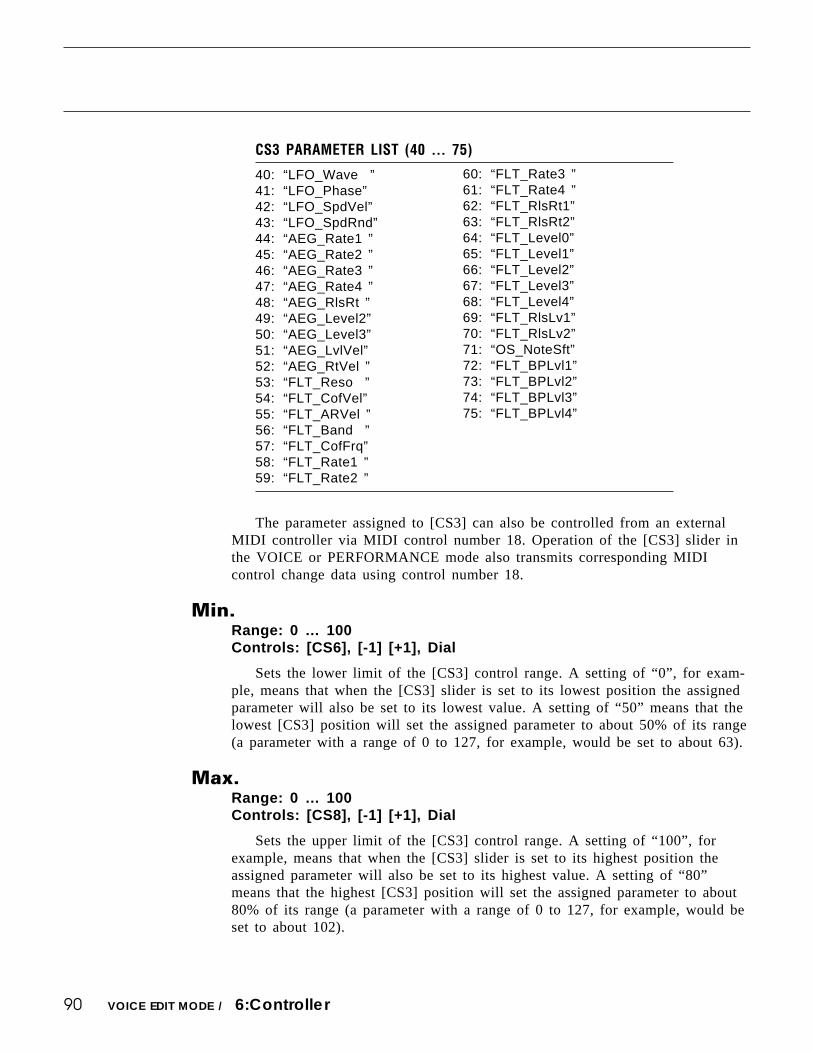
90 VOICE EDIT MODE / 6:Controller
CS3 PARAMETER LIST (40 … 75)
40: “LFO_Wave ”41: “LFO_Phase”42: “LFO_SpdVel”43: “LFO_SpdRnd”44: “AEG_Rate1 ”45: “AEG_Rate2 ”46: “AEG_Rate3 ”47: “AEG_Rate4 ”48: “AEG_RlsRt ”49: “AEG_Level2”50: “AEG_Level3”51: “AEG_LvlVel”52: “AEG_RtVel ”53: “FLT_Reso ”54: “FLT_CofVel”55: “FLT_ARVel ”56: “FLT_Band ”57: “FLT_CofFrq”58: “FLT_Rate1 ”59: “FLT_Rate2 ”
60: “FLT_Rate3 ”61: “FLT_Rate4 ”62: “FLT_RlsRt1”63: “FLT_RlsRt2”64: “FLT_Level0”65: “FLT_Level1”66: “FLT_Level2”67: “FLT_Level3”68: “FLT_Level4”69: “FLT_RlsLv1”70: “FLT_RlsLv2”71: “OS_NoteSft”72: “FLT_BPLvl1”73: “FLT_BPLvl2”74: “FLT_BPLvl3”75: “FLT_BPLvl4”
The parameter assigned to [CS3] can also be controlled from an externalMIDI controller via MIDI control number 18. Operation of the [CS3] slider inthe VOICE or PERFORMANCE mode also transmits corresponding MIDIcontrol change data using control number 18.
Min.Range: 0 … 100Controls: [CS6], [-1] [+1], Dial
Sets the lower limit of the [CS3] control range. A setting of “0”, for exam-ple, means that when the [CS3] slider is set to its lowest position the assignedparameter will also be set to its lowest value. A setting of “50” means that thelowest [CS3] position will set the assigned parameter to about 50% of its range(a parameter with a range of 0 to 127, for example, would be set to about 63).
Max.Range: 0 … 100Controls: [CS8], [-1] [+1], Dial
Sets the upper limit of the [CS3] control range. A setting of “100”, forexample, means that when the [CS3] slider is set to its highest position theassigned parameter will also be set to its highest value. A setting of “80”means that the highest [CS3] position will set the assigned parameter to about80% of its range (a parameter with a range of 0 to 127, for example, would beset to about 102).

91
6: CS4 PARAMETER EDIT
The [CS3] and [CS4] sliders can be assigned to control a wide range of voiceparameters in real time while playing the SY85. These parameters assign a voiceparameter to the [CS4] slider, and set the maximum and minimum limits of thecontrol range.
[VOICE] → [EDIT] → [MENU] → 6:Controller → [ENTER/YES] → [ENTER/YES] →→ [MENU] → 6:CS4 Parameter → [ENTER/YES]
VOICE EDIT MODE / 6:Controller
CS4 Param (CS4 parameter)Range: 0 … 75Controls: [CS1], [-1] [+1], Dial
Assigns any of 75 different voice parameters to be controlled via the [CS4]slider.
The numbers and abbreviations associated with each voice parameter arelisted below:
F1
CS1
F2
CS2
F3
CS3
F4
CS4
F5
CS5
F6
CS6
F7
CS7
F8
CS8
CTRL`CS4`Param(CTRL#=19)``Min.``````Max.
```0:No»Assign``````````````0%``````100%
CS4 PARAMETER LIST (0 … 39)
0: “No_Assign ”1: “CT_MW_Pmod”2: “CT_MW_Amod”3: “CT_MW_Fmod”4: “CT_MW_Coff”5: “CT_MW_EGBs”6: “CT_FC_Pmod”7: “CT_FC_Amod”8: “CT_FC_Fmod”9: “CT_FC_Coff”10: “CT_FC_EGBs”11: “CT_AT_Pmod”12: “CT_AT_Amod”13: “CT_AT_Fmod”14: “CT_AT_Coff”15: “CT_AT_EGBs”16: “CT_AT_PtBs”17: “CT_PBRange”18: “CT_VLLoLim”19: “TotalLevel”
20: “EF_SendLvl”21: “OS_FrqFine”22: “OS_Random ”23: “PEG_Rate1 ”24: “PEG_Rate2 ”25: “PEG_Rate3 ”26: “PEG_RlsRt ”27: “PEG_Level0”28: “PEG_Level1”29: “PEG_Level2”30: “PEG_Level3”31: “PEG_RlsLvl”32: “PEG_Range ”33: “PEG_LvlVel”34: “PEG_RtVel ”35: “LFO_Speed ”36: “LFO_Delay ”37: “LFO_Pmod ”38: “LFO_Amod ”39: “LFO_Fmod ”

92 VOICE EDIT MODE / 6:Controller
CS4 PARAMETER LIST (40 … 75)
40: “LFO_Wave ”41: “LFO_Phase”42: “LFO_SpdVel”43: “LFO_SpdRnd”44: “AEG_Rate1 ”45: “AEG_Rate2 ”46: “AEG_Rate3 ”47: “AEG_Rate4 ”48: “AEG_RlsRt ”49: “AEG_Level2”50: “AEG_Level3”51: “AEG_LvlVel”52: “AEG_RtVel ”53: “FLT_Reso ”54: “FLT_CofVel”55: “FLT_ARVel ”56: “FLT_Band ”57: “FLT_CofFrq”58: “FLT_Rate1 ”59: “FLT_Rate2 ”
60: “FLT_Rate3 ”61: “FLT_Rate4 ”62: “FLT_RlsRt1”63: “FLT_RlsRt2”64: “FLT_Level0”65: “FLT_Level1”66: “FLT_Level2”67: “FLT_Level3”68: “FLT_Level4”69: “FLT_RlsLv1”70: “FLT_RlsLv2”71: “OS_NoteSft”72: “FLT_BPLvl1”73: “FLT_BPLvl2”74: “FLT_BPLvl3”75: “FLT_BPLvl4”
The parameter assigned to [CS4] can also be controlled from an externalMIDI controller via MIDI control number 19. Operation of the [CS4] slider inthe VOICE or PERFORMANCE mode also transmits corresponding MIDIcontrol change data using control number 19.
Min (Minimum parameter value)Range: 0 … 100Controls: [CS6], [-1] [+1], Dial
Sets the lower limit of the [CS4] control range. A setting of “0”, for exam-ple, means that when the [CS4] slider is set to its lowest position the assignedparameter will also be set to its lowest value. A setting of “50” means that thelowest [CS4] position will set the assigned parameter to about 50% of its range(a parameter with a range of 0 to 127, for example, would be set to about 63).
Max (Maximum parameter value)Range: 0 … 100Controls: [CS8], [-1] [+1], Dial
Sets the upper limit of the [CS4] control range. A setting of “100”, forexample, means that when the [CS4] slider is set to its highest position theassigned parameter will also be set to its highest value. A setting of “80”means that the highest [CS4] position will set the assigned parameter to about80% of its range (a parameter with a range of 0 to 127, for example, would beset to about 102).

93
This function allows the controller parameters from any other voice (the “source”voice) to be copied to the current voice. You can copy a controller setup that is closeto the type you want, then edit it to produce the required sound.
CONTROLLER DATA COPY[VOICE] → [EDIT] → [MENU] → 6:Controller → [ENTER/YES] → [ENTER/YES] → [COPY]
VOICE EDIT MODE / 6:Controller
From VoiceRange: Any INTERNAL or CARD voiceControls: MEMORY, GROUP, PROGRAM, [CS5], [-1] [+1], Dial
Use the [INTERNAL 1], [INTERNAL 2], and [CARD] MEMORY keys toselect the memory area from which the source voice is to be selected. Use theGROUP keys to select the source voice bank, then use the PROGRAM keys toselect the source voice number. The [CS5] slider and other data entry controlscan also be used to select the source voice number.
Once the source voice has been selected, press the [ENTER/YES] key. “Areyou sure?” will appear on the display.
CONTROLLER`COPY`From`Voice``````````````
Are`you`sure`?```````¡A1:InitVce
Press the [ENTER/YES] key again to copy the controller data, or press[EXIT/NO] to cancel the copy operation. Once the copy operation has finished,“Completed!” will appear on the display briefly, then the display will return tothe controller edit mode.
F1
CS1
F2
CS2
F3
CS3
F4
CS4
F5
CS5
F6
CS6
F7
CS7
F8
CS8
CONTROLLER`COPY`From`Voice``````````````
`````````````````````¡A1:InitVce

94
The ability to independently adjust the volume of each voice makes it possible tomatch levels for smooth transition when switching between voices.
Total LevelRange: 0 … 127Controls: [CS4], [-1] [+1], Dial
Adjusts the volume of the current voice.A setting of “0” produces no sound while a setting of “127” produces
maximum volume. A bar graph to the right of the parameter provides a visualindication of volume level — the longer the bar, the higher the volume.
VOICE TOTAL LEVEL[VOICE] → [EDIT] → [MENU] → 7:Total Level → [ENTER/YES]
VOICE EDIT MODE / 7:Total Level
F1
CS1
F2
CS2
F3
CS3
F4
CS4
F5
CS5
F6
CS6
F7
CS7
F8
CS8
VOICE`Total`Level``
````````````````127ƒ``

95
Your original voices should naturally have original names. This function can beused to assign a name of up to 8 characters to the current voice.
VOICE NAME[VOICE] → [EDIT] → [MENU] → 8:Name → [ENTER/YES]
VOICE EDIT MODE / 8:Name
F1
CS1
F2
CS2
F3
CS3
F4
CS4
F5
CS5
F6
CS6
F7
CS7
F8
CS8
VOICE`Name````````````````````"InitVce`"
[CLR][UPR][LWR][SPC]````````````[†]``[¥]
NameRange: See character list, belowControls: [F1] … [F4], [F7], [F8], [CS1] … [CS8], [-1] [+1], Dial,
GROUP, PROGRAM
Assigns a name of up to 8 characters to the current voice.Use the [F7] function key to move the character cursor to the left, and the
[F8] function key to move the cursor to the right. Use the GROUP and PRO-GRAM keys to input a character at the cursor position. Each GROUP andPROGRAM key selects the three characters printed above it in sequence. It isalso possible to use the [-1] and [+1] keys or dial to scroll through the avail-able characters (see list below).
The sliders, [CS1] through [CS8], independently select characters for thecorresponding character position: [CS1] selects the first character, [CS2] selectsthe second character, and so on.
The first four function keys also perform important functions: [F1] clearsthe entire name, [F2] selects upper-case characters, [F3] selects lower-casecharacters, and [F4] inserts a space at the cursor position.
[A]: A → B → C[B]: D → E → F[C]: G → H → I[D]: J → K → L[E]: M → N → O[F]: P → Q → R[G]: S → T → U[H]: V → W → X
[1]: Y → Z → 0[2]: 1 → 2 → 3[3]: 4 → 5 → 6[4]: 7 → 8 → 9[5]: * → & → _[6]: / → . → ,[7]: ’ → ! → ?[8]: # → : → ;
PROGRAM keyGROUP key

96
These parameters provide a fast, easy way to select a new wave for the currentvoice, and instantly set the main amplitude envelope generator parameters to valuesthat produce good results with the selected wave.
For full oscillator parameters see page 58.
1: WAVE[VOICE] → [QUICK EDIT] → [MENU] → 1:Wave → [ENTER/YES]
GroupRange: 1 … 16Controls: [CS2], [-1] [+1], Dial
For fast, easy selection of the preset SY85 waves this parameter selects 16different wave categories or “groups”, each containing a number of waves thatcan be individually selected by using the “Number” parameter, below.
Quick Edit Wave Groups
1:Piano Acoustic pianos2:Key Other keyboards3:Brass Brass instruments4:Wind Wind instruments5:Strings Strings6:A.Guitar Acoustic guitars7:E.Guitar Electric guitars8:Bass Acoustic & electric bass9:Folk Folk & ethnic instruments10:Synth Synthesizer sounds11:Choir Choir & human voice12:TPerc Tuned percussion13:Drum Drums14:Perc Percussion instruments15:SE Sound effects16:Osc Basic oscillator waveforms
VOICE EDIT MODE / QUICK EDIT
F1
CS1
F2
CS2
F3
CS3
F4
CS4
F5
CS5
F6
CS6
F7
CS7
F8
CS8
QED`WAVE)Group``````Number``
```````16:Osc```````P244:Sin

97
NumberRange: P001 … P244, I00 … I63, C00 … C63Controls: MEMORY, [CS5], [-1] [+1], Dial
Selects the wave (AWM waveform) to be used in the current voice. Use the“Group” parameter, above, to select the group containing the wave that is to beselected. The [INTERNAL 1], [INTERNAL 2], and [CARD] keys can also beused to select the memory area from which the wave is to be selected. Acomplete listing of the internal waves is given in the Appendix, on page 310.
VOICE EDIT MODE / QUICK EDIT

98
Rather than having to set numerous level and rate values via the full-edit ampli-tude EG parameters, these parameters let you select from a range of preset envelopetypes, and then modify the overall attack, sustain, and release characteristics as re-quired.
For full amplitude EG parameters see page 60.
2: AMPLITUDE EG[VOICE] → [QUICK EDIT] → [MENU] → 2:AEG → [ENTER/YES]
VOICE EDIT MODE / QUICK EDIT
Type (Envelope type)Range: 00 … 21Controls: [CS1], [-1] [+1], Dial
Selects either the envelope defined by the current amplitude envelope pa-rameter settings (page 60), or one of 21 preset amplitude envelope types for thecurrent voice. The envelope types are:
Quick Edit Envelope Types
00:-------- Full-edit envelope01:Piano Acoustic piano02:Brass Brass03:SfzBrass Sforzando brass04:SynBrass Synthesizer brass05:StFast Fast-attack strings06:StSlw/Pd Slow-attack strings (pad)07:E.Bass Electric bass08:SynBass1 Synthesizer bass 109:SynBass2 Synthesizer bass 210:Organ Organ11:Guitar Guitar12:Pluck1 Plucked instrument 113:Pluck2 Pluched instrument 214:SynPad Synthesizer pad15:SynComp Synthesizer comping (backing)16:Percusiv Percussive17:S.Ideal1 Sound envelope 118:S.Ideal2 Sound envelope 219:S.Ideal3 Sound envelope 320:S.Ideal4 Sound envelope 421:Init Initialized envelope
F1
CS1
F2
CS2
F3
CS3
F4
CS4
F5
CS5
F6
CS6
F7
CS7
F8
CS8
QED`AEG)Type`````````Atk``Sus``Rel``Vel`
``0:--------``````````63```63```50```+0`

99
Atk (Attack rate)Range: 0 … 63Controls: [CS5], [-1] [+1], Dial
Sets the attack rate for the selected envelope. “63” produces the fastestattack, while “0” produces the slowest attack.
Sus (Sustain level)Range: 0 … 63Controls: [CS6], [-1] [+1], Dial
Sets the sustain level for the selected envelope.
Rel (Release rate)Range: 0 … 63Controls: [CS7], [-1] [+1], Dial
Sets the release rate for the selected envelope.
Velo (Velocity sensitivity)Range: -7 … +7Controls: [CS8], [-1] [+1], Dial
Determines how the output level of the current voice changes in response tovelocity changes (e.g. keyboard dynamics).
Plus “+” settings produce higher output level in response to higher velocityvalues — i.e. the harder a key is played, the louder the sound. The maximumsetting of “+7” produces the maximum level variation in response to velocitychanges. Minus “-” settings produce the opposite effect: lower level in responseto higher velocity. A setting of “+0” results in no level variation.
VOICE EDIT MODE / QUICK EDIT

100
The simplified filter parameters provided here have been specifically created forfast, efficient filter programming.
For full filter parameters see page 65.
[VOICE] → [QUICK EDIT] → [MENU] → 3:Filter → [ENTER/YES]
Type (Filter type)Range: 0 … 15Controls: [CS3], [-1] [+1], Dial
Selects either the filter defined by the current filter parameter settings (page65), or one of 15 preset filter types for the current voice. The filter types are:
Quick Edit Filter Types
0:-------- Full-edit filter1:VeloSoft Velocity sensitive, soft response2:VeloWide Velocity sensitive, wide response3:VeloHard Velocity sensitive, hard response4:VeloReso Velocity sensitive, resonant5:SynBass1 Synthesizer bass 16:SynBass2 Synthesizer bass 27:SynBras1 Synthesizer brass 18:SynBras2 Synthesizer brass 29:Sweep Sweep-frequency filter10:SlowAtak Slow-attack filter11:LPF_Init Initialized LPF12:HPF_Init Initialized HPF13:BPF_Init Initialized BP14:BEF_Init Initialized BEF15:Thru No filter
Coff (Cutoff frequency)Range: 0 … 127Controls: [CS6], [-1] [+1], Dial
Sets the cutoff frequency of the selected filter.Lower cutoff values produce a lower cutoff frequency and higher values
produce a higher cutoff frequency. If the “Thru” filter type is selected, nocutoff frequency can be set and “---” appears on the display in place of theparameter.
VOICE EDIT MODE / QUICK EDIT
F1
CS1
F2
CS2
F3
CS3
F4
CS4
F5
CS5
F6
CS6
F7
CS7
F8
CS8
QED`FILTER)Type```````````Coff`Reso``Vel
`````````````0:--------```---```--```+0`
3: FILTER
101
Reso (Resonance)Range: 0 … 99Controls: [CS7], [-1] [+1], Dial
Determines the degree of filter resonance.This parameter has a similar effect to the “resonance” settings on traditional
analog synthesizer filters — i.e. it determines the height of a peak in the filterresponse at the cutoff frequency. If a filter type other than “LPF” is selected,no resonance can be produced and “---” appears on the display in place of theparameter.
VOICE EDIT MODE / QUICK EDIT
Higher resonance values produce a higher resonant peak and reduce theoverall bandwidth of the filter, passing a narrow band of frequencies at thefilter’s cutoff.
Vel (Velocity sensitivity)Range: -63 … +63Controls: [CS8], [-1] [+1], Dial
Determines how the filter cutoff frequency changes in response to velocitychanges (e.g. keyboard dynamics).
Plus “+” settings produce higher cutoff frequencies in response to highervelocity values — i.e. the harder a key is played, the higher the cutoff fre-quency. The maximum setting of “+63” produces the maximum level variationin response to velocity changes. Minus “-” settings produce the opposite effect:lower cutoff in response to higher velocity. A setting of “+0” results in nocutoff variation.

102
Here, the main LFO parameters are simplified and concentrated in a single screenfor quick, easy programming.
For full LFO parameters see page 78.
Type (LFO modulation type)Range: --------, vibrato, tremolo, wahwahControls: [CS3], [-1] [+1], Dial
Determines whether the LFO will produce vibrato (pitch modulation),tremolo (amplitude modulation), or wahwah (filter cutoff modulation) effects.The current LFO parameter settings (page 78) are selected when this parameteris set to “--------”.
SpeedRange: 0 … 99Controls: [CS5], [-1] [+1], Dial
Sets the speed of the LFO.“0” is the slowest speed setting, producing an LFO speed of approximately
0 Hertz. The fastest setting of 99 produces an LFO speed of approximately 25Hertz.
DepthRange: 0 … 127Controls: [CS6], [-1] [+1], Dial
Sets the maximum amount of amplitude (tremolo), pitch (vibrato), or filtercutoff (wahwah) modulation that can be applied to the current voice.
A “0” setting produces no modulation while a setting of “127” producesmaximum modulation.
4: LFO[VOICE] → [QUICK EDIT] → [MENU] → 4:LFO → [ENTER/YES]
VOICE EDIT MODE / QUICK EDIT
F1
CS1
F2
CS2
F3
CS3
F4
CS4
F5
CS5
F6
CS6
F7
CS7
F8
CS8
QED`LFO)```Type`````Speed``Depth``
```````````--------```64```---``

103
The SY85 features a complex, high-performance effect system that can be pro-grammed easily via the parameters presented here and in the following screen.
For a complete list of effect parameters see page 274.
Effect Type 1/2Range: 0 … 90Controls: [CS1]/[CS4], [-1] [+1], Dial
[CS1] selects any of the SY85’s 90 effect types for the EFFECT 1 proces-sor, and [CS4] does the same for the EFFECT 2 processor. See page 254 formore details on the SY85 effect system.
Wet BalanceRange: 0 … 100Controls: [CS8], [-1] [+1], Dial
[CS8] controls the balance between the direct no-effect sound and the effectsound delivered via the OUTPUT 1 jacks. The maximum setting of “100”produces maximum effect depth.
5: EFFECT TYPE[VOICE] → [QUICK EDIT] → [MENU] → 5:Effect Type → [ENTER/YES]
VOICE EDIT MODE / QUICK EDIT
F1
CS1
F2
CS2
F3
CS3
F4
CS4
F5
CS5
F6
CS6
F7
CS7
F8
CS8
QED`EFFECT)```Type```````````Wet`Balance
``06:Rev.Stage1``00:Through``````````50%

104
6: EFFECT PARAMETER[VOICE] → [QUICK EDIT] → [MENU] → 6:Effect Param → [ENTER/YES]
This screen provides access to the four main parameters each for the currentselected effect 1 and effect 2. The four effect 1 parameters are edited via [CS1]through [CS4], while the four effect 2 parameters are edited via [CS5] through [CS8].
The parameters are different for each effect (refer to page 274 for details). TheEFFECT mode PARAMETERS screen described on page 109 provides full access toall 8 effect parameters.
VOICE EDIT MODE / QUICK EDIT
F1
CS1
F2
CS2
F3
CS3
F4
CS4
F5
CS5
F6
CS6
F7
CS7
F8
CS8
QED`EF`PARAM)`<```Stge>``)LPF`````[kHz](
`2.5``1.0```45``1.0``---``---``---``---

105
The SY85 features a dual-processor effect system that includes 90 top-qualitydigital effects. Two different effects can be connected in series or parallel, providingan extensive range of possible configurations.
1: MODE, TYPE[VOICE] → [EFFECT EDIT] → [MENU] → 1:Mode, Type → [ENTER/YES]
ModeRange: 0:off, 1:seri, 2:paraControls: [CS1], [-1] [+1], Dial
Determines whether the SY85’s two effect processors are connected inseries (“1:seri”) or in parallel (“2:para”), or whether the entire effect system isturned off (“0:off”).
EF1 TypeRange: 0 … 90Controls: [CS3], [-1] [+1], Dial
Selects any of the SY85’s 90 effect types for the EFFECT 1 processor. Seepage 254 for more details on the SY85 effect system, and page 274 for acomplete list of the available effects.
EF2 TypeRange: 0 … 90Controls: [CS6], [-1] [+1], Dial
Selects any of the SY85’s 90 effect types for the EFFECT 2 processor. Seepage 254 for more details on the SY85 effect system, and page 274 for acomplete list of the available effects.
VOICE EDIT MODE / EFFECT EDIT
F1
CS1
F2
CS2
F3
CS3
F4
CS4
F5
CS5
F6
CS6
F7
CS7
F8
CS8
EF`Mode`````EF1`Type```````EF2`Type``
```2:para```06:Rev.Stage1``00:Through

106
The balance between the direct sound of the voice and the effect sound is adelicate thing. Even slight changes can make a big different to the final sound. Theparameters provided in this screen provide precise balance control.
2: SEND, MIX, WET:DRY[VOICE] → [EFFECT EDIT] → [MENU] → 2:Send, Mix, Wet:Dry → [ENTER/YES]
Send (Send level)Range: 0 … 127Controls: [CS3], [-1] [+1], Dial
This parameter adjusts the amount of direct voice signal that is sent to theeffect processors, determining the strength of the final effect sound. A settingof “0” results in no effect, leaving only the “dry” sound of the voice. Themaximum setting of “127” produces the maximum amount of effect.
EF2 Mix (Effect 2 mix level)Range: 0 … 100Controls: [CS5], [-1] [+1], Dial
This parameter can only be used with the “serial” effect mode is selected.If any other mode is selected (“off” or “para”), “---” appears on the display inplace of the value.
If a controller is assigned to the EF2 Mix parameter (page 110), an inverse“c” will appear to the right of the parameter.
Out1 WetRange: 0 … 100Controls: [CS7], [-1] [+1], Dial
This parameter and the “Out1 Dry” parameter, below, work together tobalance the effect (“wet”) and direct (“dry”) signals delivered via the OUTPUT1 jacks. Higher “Out1 Wet” values produce more effect sound in relation to thedirect, dry sound of the voice.
Although the “Wet” and “Dry” parameters can be set independently, adjust-ing one will cause the other to change so that their total is always 100(%).
If a controller is assigned to the “out1 Wet” parameter (page 110), aninverse “c” will appear to the right of the parameter.
VOICE EDIT MODE / EFFECT EDIT
F1
CS1
F2
CS2
F3
CS3
F4
CS4
F5
CS5
F6
CS6
F7
CS7
F8
CS8
EF`Level``Send```EF2`Mix```Out1`Wet:Dry`
```````````127```````---````````50`:`50`

107
Out1 DryRange: 0 … 100Controls: [CS8], [-1] [+1], Dial
This parameter and the “Out1 Wet” parameter, above, work together tobalance the effect (“wet”) and direct (“dry”) signals delivered via the OUTPUT1 jacks. Higher “Out1 Dry” values produce more direct, dry sound in relationto the effect sound.
Although the “Wet” and “Dry” parameters can be set independently, adjust-ing one will cause the other to change so that their total is always 100(%).
VOICE EDIT MODE / EFFECT EDIT

108
Depending on the selected effects the SY85 effect system can have up to fourseparate output levels that are adjusted by the parameters provided in this screen.
3: OUTPUT LEVEL[VOICE] → [EFFECT EDIT] → [MENU] → 3:Output Level → [ENTER/YES]
1a, 1b, 2a, and 2b (Effect output levels)Range: 0 … 100Controls: [CS3], [CS4], [CS7], [CS8], [-1] [+1], Dial
The [CS3] and [CS4] sliders adjust the output levels of the effect 1 “1a”and “1b” stages, respectively, while the [CS7] and [CS8] sliders adjust theoutput levels of the effect 2 “2a” and “2b” stages. A setting of “0” turns outputfrom the corresponding effect stage off, while a setting of “100” producesmaximum output level.
If the selected effect is a “single” type, then only the “1a” or “2a” outputlevel is available. If it is a “cascade” type, then only the “1b” or “2b” outputlevel is available. Both the “1a” and “1b” or “2a” and “2b” levels are availableonly if the selected effect is a “dual” type. The type of the effects currentlyselected for the effect 1 and effect 2 processors are shown in parentheses onthe bottom line of the display. See page 254 for details on the effect stages andthe SY85 effect system in general.
If a controller is assigned to any of the output level parameters (page 110),an inverse “c” will appear to the right of the parameter.
VOICE EDIT MODE / EFFECT EDIT
F1
CS1
F2
CS2
F3
CS3
F4
CS4
F5
CS5
F6
CS6
F7
CS7
F8
CS8
EF`OutLevel`1a```1b`````````````2a```2b`
`EF1(sngl)=100%``--``EF2(sngl)=100%``--`

109VOICE EDIT MODE / EFFECT EDIT
4: EFFECT 1 PARAMETERS5: EFFECT 2 PARAMETERS
[VOICE] → [EFFECT EDIT] → [MENU] → 4:EF1 Parameter → [ENTER/YES]→ 5:EF2 Parameter → [ENTER/YES]
Each of the SY85’s 90 effects has 8 parameters that can be edited via the param-eters in this screen to fine-tune the effect.
Each parameter is controlled by the corresponding slider (i.e. the slider immedi-ately below each parameter). The [-1]/[+1] keys and data entry dial can also be usedto edit the parameter at which the cursor is currently located.
Refer to page 274 for a complete listing of the parameters provided for eacheffect.
F1
CS1
F2
CS2
F3
CS3
F4
CS4
F5
CS5
F6
CS6
F7
CS7
F8
CS8
EF1`PARAM`<Rev.Stage1>```)Init`Dly`[ms](
`2.5``1.0```10````0```16````4```45``1.0

110
The SY85 [CS1] and [CS2] sliders can be assigned to control different effectparameters in real time while playing in the voice or performance modes. The param-eters provided in this screen determine which effect parameters are to be controlledby the [CS1] and [CS2] sliders, the minimum and maximum parameter values, andassign MIDI control numbers to the same parameters for MIDI effect control.
6: CONTROL PARAMETERS[VOICE] → [EFFECT EDIT] → [MENU] → 6:Control Parameter → [ENTER/YES]
CS1/CS2 (CS1/CS2 switch)Range: CS1, CS2Controls: [CS1], [-1] [+1], Dial
Selects [CS1] or [CS2] for assignment.
Parameter (Effect parameter)Range: Depends on selected effects.Controls: [CS2], [-1] [+1], Dial
Selects the effect parameter to be controlled by the currently selected slider.Since each effect has as many as 8 different parameters, the maximum numberof settings available for this parameter will be 8: “Ef1prm1” through “Ef1prm8”on the display, for example, stands for “effect 1 parameter 1” through “effect 1parameter 8”. The parameters available for each effect are different, but thename of the selected parameter will be shown between the parentheses on thetop line of the display. Parameters that can not be assigned to the sliders areindicated by dashes (“--------”) instead of a parameter name.
Min (Minimum parameter value)Range: 0 … 100Controls: [CS4], [-1] [+1], Dial
Sets the lower limit of the [CS1] or [CS2] control range. A setting of “0”,for example, means that when the slider is set to its lowest position the as-signed parameter will also be set to its lowest value. A setting of “50” meansthat the lowest slider position will set the assigned parameter to about 50% ofits range (a parameter with a range of 0 to 127, for example, would be set toabout 63).
If a controller is assigned to the “Min” parameter, an inverse “c” willappear to the right of the parameter.
VOICE EDIT MODE / EFFECT EDIT
F1
CS1
F2
CS2
F3
CS3
F4
CS4
F5
CS5
F6
CS6
F7
CS7
F8
CS8
EF`CTRL)````````(`Min``Max``Additional`
``CS1`:`0ff````````0%`100%`000:off

111
Max (Maximum parameter value)Range: 0 … 100Controls: [CS5], [-1] [+1], Dial
Sets the upper limit of the [CS1] or [CS2] control range. A setting of“100”, for example, means that when the slider is set to its highest position theassigned parameter will also be set to its highest value. A setting of “80”means that the highest slider position will set the assigned parameter to about80% of its range (a parameter with a range of 0 to 127, for example, would beset to about 102).
If a controller is assigned to the “Max” parameter, an inverse “c” willappear to the right of the parameter.
Additional (Additional MIDI control)Range: 000 … 120, AfterTch, Velocity, KeyScale, LFOControls: [CS6], [-1] [+1], Dial
This parameter allows MIDI control change numbers to be assigned to theselected effect parameters, so that they can be controlled from the SY85 con-trollers (modulation wheel, foot controller, etc) or an external MIDI device thatis capable of transmitting control change messages. Additional settings include“AfterTch” for keyboard aftertouch control, “Velocity” for keyboard velocitycontrol, “KeyScale” for key scaling control, and “LFO” for internal LFO con-trol. This is in addition to control via the [CS1] and [CS2] sliders. MIDI con-trol change numbers 000 through 120 can be assigned. Some control changenumbers are already defined, while others are not assigned to any specificcontroller (see chart below).
VOICE EDIT MODE / EFFECT EDIT
MIDI CONTROL CHANGE NUMBER/DEVICE
0: “--------”1: “Mod.Whl.”2: “Breath C”4: “Foot Cnt”5: “Porta.Tm”6: “Data Ent”7: “Main Vol”8: “Balance ”10: “Panpot ”11: “Express.”64: “Hold 1 ”65: “Porta.Sw”66: “Sostenut”67: “Soft ”69: “Hold 2 ”
91: “Effect D”92: “TremoloD”93: “Chorus D”94: “CelesteD”95: “Phaser D”96: “Inc. ”97: “Dec. ”98: “NRPN LSB”99: “NRPN MSB”100: “RPN LSB”101: “RPN MSB”121: “AfterTch”122: “Velocity”123: “KeyScale”124: “LFO ”

112
7: EFFECT LFO[VOICE] → [EFFECT EDIT] → [MENU] → 7:Control LFO → [ENTER/YES]
All of the modulation-type effects — chorus, flanging, etc. — require LFO con-trol. The SY85 has an independent effect LFO that is set up by the following param-eters.
VOICE EDIT MODE / EFFECT EDIT
Wave (LFO waveform)Range: tri, dwn, up, squ, sin, S/H, 1tmControls: [CS4], [-1] [+1], Dial
Determines the waveform of the effect LFO.
“tri” = Triangle “dwn” = Downward sawtooth“up” = Upward sawtooth “squ” = Square“sin” = Sine “S/H” = Sample and hold
“1tm” = Upward 1-shot
If a controller is assigned to the “Wave” parameter (page 110), an inverse“c” will appear to the right of the parameter.
Speed (LFO speed)Range: 0 … 99Controls: [CS6], [-1] [+1], Dial
Sets the speed of the effect LFO.“0” is the slowest Speed setting, producing an LFO speed of approximately
0 Hertz. The fastest setting of 99 produces an LFO speed of approximately 25Hertz.
If a controller is assigned to the “Speed” parameter (page 110), an inverse“c” will appear to the right of the parameter.
DelayRange: 0 … 99Controls: [CS8], [-1] [+1], Dial
Sets the delay time between the beginning of a note and the beginning ofeffect LFO operation for the selected element.
The minimum setting “0” results in no delay, while the maximum setting of“99” produces a delay of approximately 2.66 seconds before the LFO beginsoperation (5.3 seconds before it reaches maximum depth).
If a controller is assigned to the “Delay” parameter (page 110), an inverse“c” will appear to the right of the parameter.
F1
CS1
F2
CS2
F3
CS3
F4
CS4
F5
CS5
F6
CS6
F7
CS7
F8
CS8
EF`CTRL`LFO``Waveform````Speed````Delay`
``````````````∆˚∆`tri````````0````````0`

113
EFFECT DATA COPY[VOICE] → [EFFECT EDIT] → [COPY]
This function facilitates voice effect editing by allowing the effect parametersfrom any other song, voice, or performance combination to be copied to the currentvoice. You can copy an effect setup that is close to the type you want, then edit it toproduce the required sound.
VOICE EDIT MODE / EFFECT EDIT
From VoiceRange: Any song, voice or performance combinationControls: MEMORY, GROUP, PROGRAM, [CS4], [CS5], [-1] [+1], Dial
Use the [CS4] slider to select the mode containing the desired voice andeffect data (“PFM” = PERFORMANCE, “VCE” = VOICE, and “MLT” =MULTI). Use the [INTERNAL 1], [INTERNAL 2], and [CARD] MEMORYkeys to select the memory area from which the source voice is to be selected.Use the GROUP keys to select the source voice bank, then use the PROGRAMkeys to select the source voice number. The [CS5] slider and other data entrycontrols can also be used to select the source voice number.
Once the source voice has been selected, press the [ENTER/YES] key. “Areyou sure?” will appear on the display.
EFFECT`COPY`````From````````````````````
Are`you`sure`?``VCE``¡A1:InitVce
Press the [ENTER/YES] key again to copy the effect data, or press [EXIT/NO] to cancel the copy operation. Once the copy operation has finished, “Com-pleted!” will appear on the display briefly, then the display will return to theeffect edit mode.
F1
CS1
F2
CS2
F3
CS3
F4
CS4
F5
CS5
F6
CS6
F7
CS7
F8
CS8
EFFECT`COPY`````From````````````````````
````````````````VCE``¡A1:InitVce
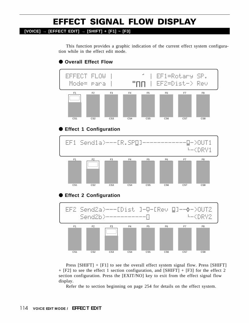
114
EFFECT SIGNAL FLOW DISPLAY[VOICE] → [EFFECT EDIT] → [SHIFT] + [F1] ~ [F3]
VOICE EDIT MODE / EFFECT EDIT
This function provides a graphic indication of the current effect system configura-tion while in the effect edit mode.
Overall Effect Flow
Effect 1 Configuration
Press [SHIFT] + [F1] to see the overall effect system signal flow. Press [SHIFT]+ [F2] to see the effect 1 section configuration, and [SHIFT] + [F3] for the effect 2section configuration. Press the [EXIT/NO] key to exit from the effect signal flowdisplay.
Refer the to section beginning on page 254 for details on the effect system.
Effect 2 Configuration
F1
CS1
F2
CS2
F3
CS3
F4
CS4
F5
CS5
F6
CS6
F7
CS7
F8
CS8
EFFECT`FLOW`Ú`∏Á∏∏∏∏∏∏Î`Ú`EF1=Rotary`SP.
`Mode=`para`Ú`∏∏∏∏∏Á∏∏`Ú`EF2=Dist->`Rev
F1
CS1
F2
CS2
F3
CS3
F4
CS4
F5
CS5
F6
CS6
F7
CS7
F8
CS8
EF1`Send1a>---[R.SPÙ]------------Ç->OUT1
`````````````````````````````````’-<DRY1
F1
CS1
F2
CS2
F3
CS3
F4
CS4
F5
CS5
F6
CS6
F7
CS7
F8
CS8
EF2`Send2a>---[Dist`]-Ÿ-[Rev`Ç]--◊->OUT2````Send2b>-----------Û``````````’-<DRY2

115
1: VOICE EDIT RECALL[VOICE] → [JOB] → [MENU] → 1:Recall → [ENTER/YES]
If you’re dissatisfied with the results of edits you’ve made to a voice, or haveaccidentally lost track of changes made, use the VOICE EDIT RECALL function torecall the pre-edit voice data from the SY85’s voice backup buffer memory.
Press [ENTER/YES] to begin the recall procedure. The following confirma-tion display will appear:
VOICE`JOB`Recall``````````````<InitVce`>
Are`you`sure`?
Press [ENTER/YES] again to confirm that you want to go ahead with therecall operation (which will erase all current edited data), or press [EXIT/NO]to cancel.
When the original voice data has been recalled, “Completed!” will appearbriefly on the display, then the display will return to the mode that was en-gaged prior to calling the voice edit recall function.
VOICE EDIT MODE / JOB
F1
CS1
F2
CS2
F3
CS3
F4
CS4
F5
CS5
F6
CS6
F7
CS7
F8
CS8
VOICE`JOB`Recall``````````````<InitVce`>
``

116
2: VOICE INITIALIZE[VOICE] → [JOB] → [MENU] → 2:Initialize → [ENTER/YES]
When you want to program a totally new voice “from scratch,” rather than editingan existing voice, use this function to initialize all voice parameters.
Press [ENTER/YES] to begin the initialize procedure. The following confir-mation display will appear:
VOICE`JOB`Initialize`
Are`you`sure`?
Press [ENTER/YES] again to confirm that you want to go ahead with theinitialize operation (which will erase all current edited data), or press [EXIT/NO] to cancel.
When the voice data has been initialized, “Completed!” will appear brieflyon the display, then the display will return to the mode that was engaged priorto calling the voice initialize function.
VOICE EDIT MODE / JOB
F1
CS1
F2
CS2
F3
CS3
F4
CS4
F5
CS5
F6
CS6
F7
CS7
F8
CS8
VOICE`JOB`Initialize`
`

117
VOICE COMPARE[SHIFT] + [STORE]
The voice compare function makes it possible to compare the sound of a voicebeing edited with the same voice prior to editing.
VOICE EDIT MODE / COMPARE
To temporarily recall the original voice while editing, press the [STORE] keywhile holding the [SHIFT] key. The [VOICE] LED will flash, indicating that thecompare mode is engaged. Data cannot be edited in the compare mode. Press [EXIT/NO] again to return to the edit mode and the voice being edited.

118
VOICE STORE[STORE]
When you’re satsfied with a new voice you’ve created in the voice edit mode, usethe store function described below to store the new voice to an internal or cardmemory location.
VOICE EDIT MODE / STORE
When you’ve finished editing, return to the normal voice play mode (pressthe [VOICE] key), and before selecting a different voice press the [STORE]key. You can now use the MEMORY, GROUP, and NUMBER keys to selectthe memory location to which your new voice is to be stored.
Once the store location has been specified, press [ENTER/YES] to beginthe store procedure. The following confirmation display will appear:
VOICE`STORE``````````To
Are`you`sure`?```````¡A1:InitVce
Press [ENTER/YES] again to confirm that you want to go ahead with thestore operation (which will erase all previous data in the specified memorylocation), or press [EXIT/NO] to cancel.
When the voice data has been stored, “Completed!” will appear briefly onthe display, then the display will return to the mode that was engaged prior tocalling the store function.
F1
CS1
F2
CS2
F3
CS3
F4
CS4
F5
CS5
F6
CS6
F7
CS7
F8
CS8
VOICE`STORE``````````To
`````````````````````¡A1:InitVce

DRUM VOICE EDIT MODE

120
1: KEY PARAMETERS 1[VOICE] → [EDIT] → [MENU] → 1:Key Param1 → [ENTER/YES]
DRUM VOICE EDIT MODE / DRUM KEY EDIT
Key NumberRange: C1 … C5Controls: [CS1], [-1] [+1], Dial, Keyboard
Selects the the drum key to be edited. In addition to using the [CS1] slider,data entry dial, and [-1] and [+1] keys, the drum key can be selected by simplypressing the appropriate key on the keyboard.
WaveRange: P001 … P244, I00 … I63, C00 … C63Controls: MEMORY, [CS4], [-1] [+1], Dial
Selects the wave (AWM waveform) to be played by the current drum key.Use the [INTERNAL 1], [INTERNAL 2], and [CARD] keys to select thememory area from which the wave is to be selected. A complete listing of theinternal waves is given in the Appendix, on page 310.
VolRange: 0 … 127Controls: [CS5], [-1] [+1], Dial
For optimum balance between the instruments in a drum “kit,” this param-eter allows the volume of the current drum key to be adjusted independently. Asetting of “0” produces no sound, while a setting of “127” produces maximumvolume.
NsftRange: -48 … +36Controls: [CS6], [-1] [+1], Dial
Shifts the pitch of selected drum key up or down in semitone steps.A setting of “-12,” for example, shifts the pitch of the selected layer down
by one octave; a setting of “+4” shifts the pitch up by a major third.
F1
CS1
F2
CS2
F3
CS3
F4
CS4
F5
CS5
F6
CS6
F7
CS7
F8
CS8
DRUM`KEY`<BD6`````>``Vol``Nsft`Tune`Pan`
``C1``````Wave`P156``120ƒ``+0```+0```+0`
121DRUM VOICE EDIT MODE / DRUM KEY EDIT
TuneRange: -63 … +63Controls: [CS7], [-1] [+1], Dial
Allows upward or downward pitch adjustment of the current drum key inapproximately 1.7-cent steps (a “cent” is 1/100th of a semitone).
The maximum minus setting of “-63” produces a downward pitch shift ofapproximately three quarters of a semitone, and the maximum plus setting of“+63” shifts the pitch up by the same amount. A setting of “0” produces nopitch change.
PanRange: -31 … +31Controls: [CS8], [-1] [+1], Dial
Interesting stereo effects can be produced by placing the sound of differentdrum instruments at different locations in the stereo sound field. This parameterdetermines the position in the stereo sound field in which the sound from thecurrent drum key will be heard (left to right).
Minus values represent panning to the left, and positive values representpanning to the right. “0” positions the sound of the selected layer in the centerof the stereo sound field.
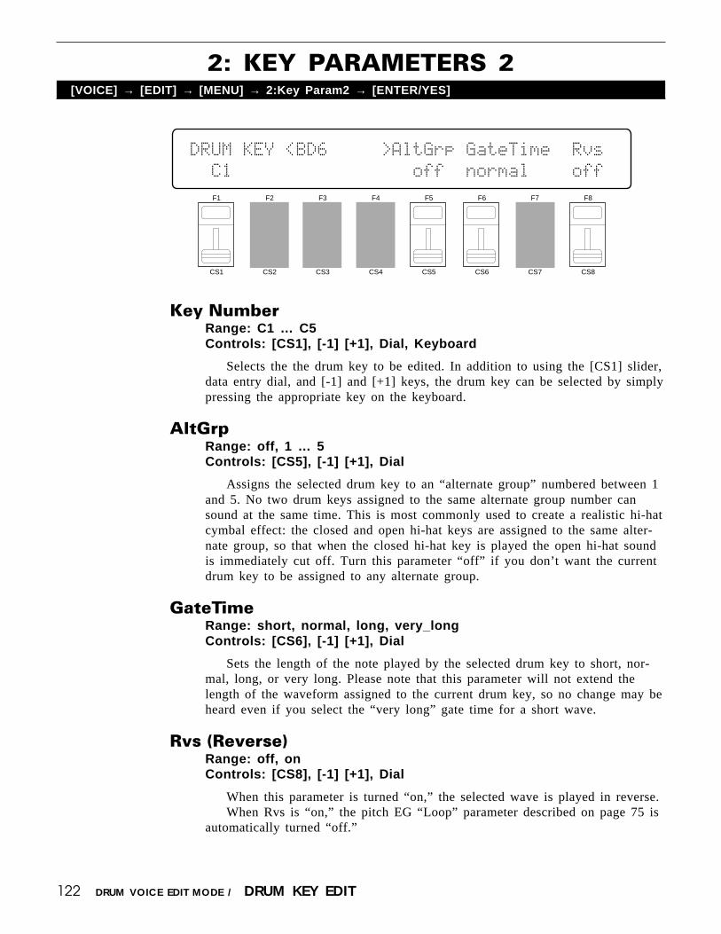
122
2: KEY PARAMETERS 2[VOICE] → [EDIT] → [MENU] → 2:Key Param2 → [ENTER/YES]
Key NumberRange: C1 … C5Controls: [CS1], [-1] [+1], Dial, Keyboard
Selects the the drum key to be edited. In addition to using the [CS1] slider,data entry dial, and [-1] and [+1] keys, the drum key can be selected by simplypressing the appropriate key on the keyboard.
AltGrpRange: off, 1 … 5Controls: [CS5], [-1] [+1], Dial
Assigns the selected drum key to an “alternate group” numbered between 1and 5. No two drum keys assigned to the same alternate group number cansound at the same time. This is most commonly used to create a realistic hi-hatcymbal effect: the closed and open hi-hat keys are assigned to the same alter-nate group, so that when the closed hi-hat key is played the open hi-hat soundis immediately cut off. Turn this parameter “off” if you don’t want the currentdrum key to be assigned to any alternate group.
GateTimeRange: short, normal, long, very_longControls: [CS6], [-1] [+1], Dial
Sets the length of the note played by the selected drum key to short, nor-mal, long, or very long. Please note that this parameter will not extend thelength of the waveform assigned to the current drum key, so no change may beheard even if you select the “very long” gate time for a short wave.
Rvs (Reverse)Range: off, onControls: [CS8], [-1] [+1], Dial
When this parameter is turned “on,” the selected wave is played in reverse.When Rvs is “on,” the pitch EG “Loop” parameter described on page 75 is
automatically turned “off.”
DRUM VOICE EDIT MODE / DRUM KEY EDIT
F1
CS1
F2
CS2
F3
CS3
F4
CS4
F5
CS5
F6
CS6
F7
CS7
F8
CS8
DRUM`KEY`<BD6`````>AltGrp`GateTime``Rvs`
``C1`````````````````off``normal````off`

123DRUM VOICE EDIT MODE / DRUM KEY EDIT
3: TOTAL LEVEL[VOICE] → [EDIT] → [MENU] → 3:Total Level → [ENTER/YES]
This parameter sets the overall volume of the current drum voice in relation tothe others, making it possible to match levels for smooth transition when switchingbetween voices.
Total LevelRange: 0 … 127Controls: [CS4], [-1] [+1], Dial
Adjusts the volume of the current drum voice.A setting of “0” produces no sound while a setting of “127” produces
maximum volume. A bar graph beside the parameter provides a visual indica-tion of volume level — the longer the bar, the higher the volume.
VolLoLimit (Minimum volume level)Range: 0 … 127Controls: [CS6], [-1] [+1], Dial
Determines the minimum volume level that can be set by the foot volumecontrol MIDI volume control data. If this parameter is set to “0,” the minimumfoot volume control position will produce almost no sound. A setting of “63”will result in about half volume when the control is set to its minimum posi-tion. This parameter does not affect keyboard velocity response.
F1
CS1
F2
CS2
F3
CS3
F4
CS4
F5
CS5
F6
CS6
F7
CS7
F8
CS8
DRUM````````TotalLevel`VolLowLimit`
````````````````127ƒ````````0``

124
4: DRUM VOICE NAME[VOICE] → [EDIT] → [MENU] → 4:Name → [ENTER/YES]
Your original drum voices should naturally have original names. This function canbe used to assign a name of up to 8 characters to the current drum voice.
NameRange: See character list, belowControls: GROUP, PROGRAM, [F1] … [F4], [F7], [F8]
[CS1] … [CS8], [-1] [+1], Dial
Assigns a name of up to 8 characters to the current drum voice.Use the [F7] function key to move the character cursor to the left, and the
[F8] function key to move the cursor to the right. Use the GROUP and PRO-GRAM keys to input a character at the cursor position. Each GROUP or PRO-GRAM key selects the three characters printed above it in sequence. It is alsopossible to use the [-1] and [+1] keys or dial to scroll through the availablecharacters (see list below).
The sliders, [CS1] through [CS8], independently select characters for thecorresponding character position: [CS1] selects the first character, [CS2] selectsthe second character, and so on.
The first four function keys also perform important functions: [F1] clearsthe entire name, [F2] selects upper-case characters for GROUP and PROGRAMkey entry, [F3] selects lower-case characters for GROUP and PROGRAM keyentry, and [F4] inserts a space at the cursor position.
DRUM VOICE EDIT MODE / DRUM KEY EDIT
F1
CS1
F2
CS2
F3
CS3
F4
CS4
F5
CS5
F6
CS6
F7
CS7
F8
CS8
DRUM`VOICE`Name```````````````"DR`PTN``"
[CLR][UPR][LWR][SPC]````````````[†]``[¥]
[A]: A → B → C[B]: D → E → F[C]: G → H → I[D]: J → K → L[E]: M → N → O[F]: P → Q → R[G]: S → T → U[H]: V → W → X
[1]: Y → Z → 0[2]: 1 → 2 → 3[3]: 4 → 5 → 6[4]: 7 → 8 → 9[5]: * → & → _[6]: / → . → ,[7]: ’ → ! → ?[8]: # → : → ;
PROGRAM keyGROUP key

125
DRUM KEY DATA COPY[VOICE] → [EDIT] → [COPY]
This function facilitates drum voice editing by allowing the data from one drumkey (the “source” key) to be copied to any other drum key. You can copy the datafrom a key that is close to the sound you want, then edit it as required.
FromRange: C1 … C5Controls: [CS5], [-1] [+1], Dial, Keyboard
ToRange: C1 … C5Controls: [CS7], [-1] [+1], Dial, Keyboard
Use the [CS5] slider to select the source (“From”) key, and the [CS7] sliderto select the destination (“To”) key. The source and destination keys can alsobe selected by simply pressing the appropriate key on the keyboard after plac-ing the cursor at the “From” or “To” parameter position by pressing the [F5] or[F7] function key, respectively. The names of the waves currently assigned tothe “From” and “To” keys are displayed above the key numbers.
Once the source and destination keys have been selected, press the [EN-TER/YES] key. “Are you sure?” will appear on the display.
DRUM`KEY`COPY`From<BD6`````>To<BD6`````>
Are`you`sure`?````````C1````¥```C1
Press the [ENTER/YES] key again to copy the drum key data, or press[EXIT/NO] to cancel the copy operation. Once the copy operation has finished,“Completed!” will appear on the display briefly, then the display will return tothe drum edit mode.
DRUM VOICE EDIT MODE / DRUM KEY EDIT
F1
CS1
F2
CS2
F3
CS3
F4
CS4
F5
CS5
F6
CS6
F7
CS7
F8
CS8
DRUM`KEY`COPY`From<BD6`````>To<BD6`````>
``````````````````````C1````¥```C1

126
1: EFFECT TYPE[VOICE] → [QUICK EDIT] → [MENU] → 1:Effect Type → [ENTER/YES]
The SY85 features a complex, high-performance effect system that can be pro-grammed easily via the parameters presented here and in the following screen.
For a complete list of effect parameters see page 274.
Effect Type 1/2Range: 0 … 90Controls: [CS1]/[CS4], [-1] [+1], Dial
[CS1] selects any of the SY85’s 90 effect types for the EFFECT 1 proces-sor, and [CS4] does the same for the EFFECT 2 processor. See page 254 formore details on the SY85 effect system.
Wet Balance 1/2Range: 0 … 100Controls: [CS7]/[CS8], [-1] [+1], Dial
[CS7] controls the balance between the direct no-effect sound and the effectsound of the EFFECT 1 processor, while [CS8] does the same for the EFFECT2 processor. The higher the value the deeper the effect. See page 254 for moredetails on the SY85 effect system.
DRUM VOICE EDIT MODE / QUICK EDIT
F1
CS1
F2
CS2
F3
CS3
F4
CS4
F5
CS5
F6
CS6
F7
CS7
F8
CS8
QED`EFFECT)```Type```````````Wet`Balance
``03:Rev.Room1```12:Rev.Basmnt``40%``10%

127
2: EFFECT SEND LEVEL[VOICE] → [QUICK EDIT] → [MENU] → 2:Effect Send → [ENTER/YES]
The ability to set different effect send levels for each drum key provides ex-tremely fine control over the drum effect sound.
DRUM VOICE EDIT MODE / QUICK EDIT
KeyRange: C1 … C5Controls: [CS2], [-1] [+1], Dial, keyboard
Selects the drum key (C1 … C5) for which the send level is to be adjusted.Use either the [CS2] slider or the keyboard to enter the key number.
Send LevelRange: 0 … 127Controls: [CS4], [-1] [+1], Dial
Sets the effect send level for the selected drum key.
F1
CS1
F2
CS2
F3
CS3
F4
CS4
F5
CS5
F6
CS6
F7
CS7
F8
CS8
QED`EFFECT)Send`Level`````````<BD6`````>
````Key=`C1`````127

128
1: MODE, TYPE[VOICE] → [EFFECT EDIT] → [MENU] → 1:Mode Type → [ENTER/YES]
The SY85 features a dual-processor effect system that includes 90 top-qualitydigital effects. Two different effects can be connected in series or parallel, providingan extensive range of possible configurations.
ModeRange: 0:off, 1:seri, 2:paraControls: [CS1], [-1] [+1], Dial
Determines whether the SY85’s two effect processors are connected inseries (“1:seri”) or in parallel (“2:para”), or whether the entire effect system isturned off (“0:off”).
EF1 TypeRange: 0 … 90Controls: [CS3], [-1] [+1], Dial
Selects any of the SY85’s 90 effect types for the EFFECT 1 processor. Seepage 254 for more details on the SY85 effect system, and page 274 for acomplete list of the available effects.
EF2 TypeRange: 0 … 90Controls: [CS6], [-1] [+1], Dial
Selects any of the SY85’s 90 effect types for the EFFECT 2 processor. Seepage 254 for more details on the SY85 effect system, and page 274 for acomplete list of the available effects.
DRUM VOICE EDIT MODE / EFFECT EDIT
F1
CS1
F2
CS2
F3
CS3
F4
CS4
F5
CS5
F6
CS6
F7
CS7
F8
CS8
EF`Mode`````EF1`Type```````EF2`Type``
```2:para```03:Rev.Room1```12:Rev.Basmnt

129
2: KEY SEND SELECT & LEVEL[VOICE] → [EFFECT EDIT] → [MENU] → 2:Send → [ENTER/YES]
The parameters provided here determine to which of the SY85 effect stages theoutput from each drum key is sent, and at what level. It is also possible to controlthe effect send level via keyboard dynamics.
KeyRange: C1 … C5Controls: [CS2], [-1] [+1], Dial, Keyboard
Selects the drum key (C1 … C5) for which the send select and level param-eters are to be adjusted. Use either the [CS2] slider or the keyboard to enterthe key number.
Switch 1a, 1b/2a, 2bRange: See text belowControls: [CS5]/[CS6], [-1] [+1], Dial
Determines to which of the EFFECT 1 and EFFECT 2 effect stages theoutput from the current layer is sent. Each time the [F5] or [F6] function key ispressed, the cursor alternately moves to the corresponding “a” or “b” parameter.The [-1] and [+1] keys can then be used to turn the stage on (“a” or “b”) oroff (“.”). The [CS5] and [CS6] sliders select the following settings in sequence:
CS5 (EFFECT 1) CS6 (EFFECT 2)
1./. (a and b off) 2./. (a and b off)1a/. (a on, b off) 2a/. (a on, b off)1a/b (a and b on) 2a/b (a and b on)1./b (a off, b on) 2./b (a off, b on)
If a “single” type effect is selected then only stage “a” can be selected. If a“cascade” type effect is selected, then only stage “b” can be selected. If a“dual” type effect is selected, then both stages “a” and “b” can be selected. Aneffect stage that cannot be selected is represented by “-” on the display.
DRUM VOICE EDIT MODE / EFFECT EDIT
F1
CS1
F2
CS2
F3
CS3
F4
CS4
F5
CS5
F6
CS6
F7
CS7
F8
CS8
EF`Send`<BD6`````>``Switch`````Levl`VelS
``Key=`C1````````````1./-`2./-``127```+0

130
Send (Send level)Range: 0 … 127Controls: [CS7], [-1] [+1], Dial
This parameter adjusts the amount of direct voice signal that is sent to theeffect processors, determining the strength of the final effect sound. A settingof “0” results in no effect, leaving only the “dry” sound of the voice. Themaximum setting of “127” produces the maximum amount of effect.
VelS (Send velocity sensitivity)Range: -7 … +7Controls: [CS8], [-1] [+1], Dial
Determines how the send level from the selected drum key is affected byvelocity changes (e.g. keyboard dynamics).
Plus “+” settings produce higher send levels in response to higher velocityvalues — i.e. the harder a key is played, the higher the send level, and there-fore the deeper the effect. The maximum setting of “+7” produces the maxi-mum level variation in response to velocity changes. Minus “-” settings producethe opposite effect: lower send level in response to higher velocity. A setting of“+0” results in no send level variation.
DRUM VOICE EDIT MODE / EFFECT EDIT

131DRUM VOICE EDIT MODE / EFFECT EDIT
3: KEY DRY OUTPUT SELECT[VOICE] → [EFFECT EDIT] → [MENU] → 3:Key Dry Out Select → [ENTER/YES]
These parameters determine turn the “dry lines” (i.e. the signal paths which by-passes each effect processor) on or off, determining whether any dry signal outputcan occur at OUTPUT 1 and OUTPUT 2.
KeyRange: C1 … C5Controls: [CS2], GROUP [A] … [D], [-1] [+1], Dial
Selects the key to be edited. The name of the voice assigned to the selectedkey is shown between parentheses on the upper line of the display.
Dry1Range: off, onControls: [CS6], [-1] [+1], Dial
Turns the “dry line” bypassing the EFFECT 1 signal processor on or off.When this parameter is turned “off,” the “WET:DRY BALANCE” parameters(page 133) have no effect.
Dry2Range: off, onControls: [CS7], [-1] [+1], Dial
Turns the “dry line” bypassing the EFFECT 2 signal processor on or off.When this parameter is turned “off,” the “WET:DRY BALANCE” parameters(page 133) have no effect.
F1
CS1
F2
CS2
F3
CS3
F4
CS4
F5
CS5
F6
CS6
F7
CS7
F8
CS8
OUTPUT`Select`<BD6`````>`Dry1`Dry2```
``Key=`C1``````````````````on```on``

132 DRUM VOICE EDIT MODE / EFFECT EDIT
Depending on the selected effects the SY85 effect system can have up to fourseparate output levels that are adjusted by the parameters provided in this screen.
1a, 1b, 2a, and 2b (Effect output levels)Range: 0 … 100Controls: [CS3], [CS4], [CS7], [CS8], [-1] [+1], Dial
The [CS3] and [CS4] sliders adjust the output levels of the effect 1 “1a”and “1b” stages, respectively, while the [CS7] and [CS8] sliders adjust theoutput levels of the effect 2 “2a” and “2b” stages. A setting of “0” turns outputfrom the corresponding effect stage off, while a setting of “100” producesmaximum output level.
If the selected effect is a “single” type, then only the “1a” or “2a” outputlevel is available. If it is a “cascade” type, then only the “1b” or “2b” outputlevel is available. Both the “1a” and “1b” or “2a” and “2b” levels are availableonly if the selected effect is a “dual” type. The type of the effects currentlyselected for the effect 1 and effect 2 processors are shown in parentheses onthe bottom line of the display. See page 254 for details on the effect stages andthe SY85 effect system in general.
If a controller is assigned to any of the output level parameters (page 136),an inverse “c” will appear to the right of the parameter.
4: OUTPUT LEVEL[VOICE] → [EFFECT EDIT] → [MENU] → 4:Output Level → [ENTER/YES]
F1
CS1
F2
CS2
F3
CS3
F4
CS4
F5
CS5
F6
CS6
F7
CS7
F8
CS8
EF`OutLevel`1a```1b`````````````2a```2b`
`EF1(sngl)=100%``--``EF2(sngl)=`98%``--
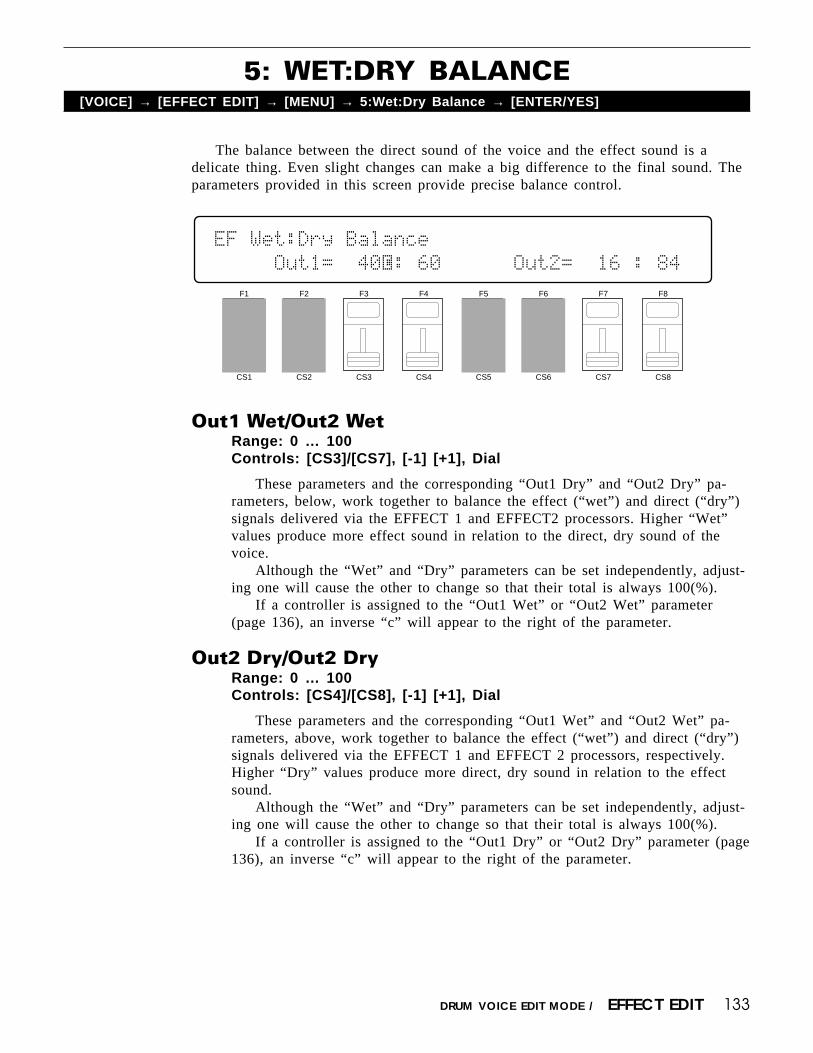
133
5: WET:DRY BALANCE[VOICE] → [EFFECT EDIT] → [MENU] → 5:Wet:Dry Balance → [ENTER/YES]
The balance between the direct sound of the voice and the effect sound is adelicate thing. Even slight changes can make a big difference to the final sound. Theparameters provided in this screen provide precise balance control.
DRUM VOICE EDIT MODE / EFFECT EDIT
Out1 Wet/Out2 WetRange: 0 … 100Controls: [CS3]/[CS7], [-1] [+1], Dial
These parameters and the corresponding “Out1 Dry” and “Out2 Dry” pa-rameters, below, work together to balance the effect (“wet”) and direct (“dry”)signals delivered via the EFFECT 1 and EFFECT2 processors. Higher “Wet”values produce more effect sound in relation to the direct, dry sound of thevoice.
Although the “Wet” and “Dry” parameters can be set independently, adjust-ing one will cause the other to change so that their total is always 100(%).
If a controller is assigned to the “Out1 Wet” or “Out2 Wet” parameter(page 136), an inverse “c” will appear to the right of the parameter.
Out2 Dry/Out2 DryRange: 0 … 100Controls: [CS4]/[CS8], [-1] [+1], Dial
These parameters and the corresponding “Out1 Wet” and “Out2 Wet” pa-rameters, above, work together to balance the effect (“wet”) and direct (“dry”)signals delivered via the EFFECT 1 and EFFECT 2 processors, respectively.Higher “Dry” values produce more direct, dry sound in relation to the effectsound.
Although the “Wet” and “Dry” parameters can be set independently, adjust-ing one will cause the other to change so that their total is always 100(%).
If a controller is assigned to the “Out1 Dry” or “Out2 Dry” parameter (page136), an inverse “c” will appear to the right of the parameter.
F1
CS1
F2
CS2
F3
CS3
F4
CS4
F5
CS5
F6
CS6
F7
CS7
F8
CS8
EF`Wet:Dry`Balance``````````
`````Out1=``40®:`60``````Out2=``16`:`84`

134
6: SEND & EFFECT 2 MIX LEVEL[VOICE] → [EFFECT EDIT] → [MENU] → 6:Mix Level → [ENTER/YES]
DRUM VOICE EDIT MODE / EFFECT EDIT
These parameters determine the mix level between each effect send and the outputof the preceding effect stage. Refer to the section beginning on page 254 for detailson the overall SY85 effect system.
EF2 Mix (Effect 2 mix level)Range: 0 … 100Controls: [CS4], [-1] [+1], Dial
Mixes the output of the EFFECT 2 processor with that of the EFFECT 1processor. This parameter can only be used with the “serial” effect mode isselected. If any other mode is selected (“off” or “para”), “---” appears on thedisplay in place of the value.
If a controller is assigned to the EF2 Mix parameter (page 136), an inverse“c” will appear to the right of the parameter.
Send 1b, 2a, 2b (Send level)Range: 0 … 100Controls: [CS6], [CS7], [CS8], [-1] [+1], Dial
These parameters mix the dry signal sent to the corresponding effect stagewith the output of the preceding effect stage. The higher the value the greatermix level. If the current effect configuration does not allow one of these mixparameters, “--” will appear in place of the mix level parameter.
If a controller is assigned to the one of these parameters (page 136), aninverse “c” will appear to the right of the parameter.
F1
CS1
F2
CS2
F3
CS3
F4
CS4
F5
CS5
F6
CS6
F7
CS7
F8
CS8
EF`Mix`Level```EF2``Insert`1b```2a```2b`
````````````````--`````````--```--```--`

135DRUM VOICE EDIT MODE / EFFECT EDIT
7: EFFECT 1 PARAMETERS8: EFFECT 2 PARAMETERS
[VOICE] → [EFFECT EDIT] → [MENU] → 7:EF1 Parameter → [ENTER/YES]→ 8:EF2 Parameter → [ENTER/YES]
Each of the SY85’s 90 effects has 8 parameters that can be edited via the param-eters in this screen to fine-tune the effect.
Each parameter is controlled by the corresponding slider (i.e. the sliderimmediately below each parameter). The [-1]/[+1] keys and data entry dial canalso be used to edit the parameter at which the cursor is currently located.
Refer to page 274 for a complete listing of the parameters provided foreach effect.
F1
CS1
F2
CS2
F3
CS3
F4
CS4
F5
CS5
F6
CS6
F7
CS7
F8
CS8
EF1`PARAM`<Rev.Room1`>```)Rev.Time``[s](
`1.2``0.8````8````0```50````4```68``5.6

136
9: CONTROL PARAMETERS[VOICE] → [EFFECT EDIT] → [MENU] → 2:Key Param2 → [ENTER/YES]
DRUM VOICE EDIT MODE / DRUM KEY EDIT
The SY85 [CS1] and [CS2] sliders can be assigned to control different effectparameters in real time while playing in the voice or performance modes. The param-eters provided in this screen determine which effect parameters are to be controlledby the [CS1] and [CS2] sliders, the minimum and maximum parameter values, andassign MIDI control numbers to the same parameters for MIDI effect control.
CS1/CS2 (CS1/CS2 switch)Range: CS1, CS2Controls: [CS1], [-1] [+1], Dial
Selects [CS1] or [CS2] for assignment.
Parameter (Effect parameter)Range: Depends on selected effects.Controls: [CS2], [-1] [+1], Dial
Selects the effect parameter to be controlled by the currently selected slider.Since each effect has as many as 8 different parameters, the maximum numberof settings available for this parameter will be 8: “Ef1prm1” through “Ef1prm8”on the display, for example, stands for “effect 1 parameter 1” through “effect 1parameter 8”. The parameters available for each effect are different, but thename of the selected parameter will be shown between the parentheses on thetop line of the display. Parameters that can not be assigned to the sliders areindicated by dashes (“--------”) instead of a parameter name.
Min (Minimum parameter value)Range: 0 … 100Controls: [CS4], [-1] [+1], Dial
Sets the lower limit of the [CS1] or [CS2] control range. A setting of “0”,for example, means that when the slider is set to its lowest position the as-signed parameter will also be set to its lowest value. A setting of “50” meansthat the lowest slider position will set the assigned parameter to about 50% ofits range (a parameter with a range of 0 to 127, for example, would be set toabout 63).
If a controller is assigned to the “Min” parameter, an inverse “c” willappear to the right of the parameter.
F1
CS1
F2
CS2
F3
CS3
F4
CS4
F5
CS5
F6
CS6
F7
CS7
F8
CS8
EF`CTRL)````````(`Min``Max``Additional`
``CS1`:`Out1`Wet```0%``40%`000:off

137
Max (Maximum parameter value)Range: 0 … 100Controls: [CS5], [-1] [+1], Dial
Sets the upper limit of the [CS1] or [CS2] control range. A setting of“100”, for example, means that when the slider is set to its highest position theassigned parameter will also be set to its highest value. A setting of “80”means that the highest slider position will set the assigned parameter to about80% of its range (a parameter with a range of 0 to 127, for example, would beset to about 102).
If a controller is assigned to the “Max” parameter, an inverse “c” willappear to the right of the parameter.
Additional (Additional MIDI control)Range: 000 … 120, AfterTch, Velocity, KeyScale, LFOControls: [CS6], [-1] [+1], Dial
This parameter allows MIDI control change numbers to be assigned to theselected effect parameters, so that they can be controlled from the SY85 con-trollers (modulation wheel, foot controller, etc) or an external MIDI device thatis capable of transmitting control change messages. Additional settings include“AfterTch” for keyboard aftertouch control, “Velocity” for keyboard velocitycontrol, “KeyScale” for key scaling control, and “LFO” for internal LFO con-trol. This is in addition to control via the [CS1] and [CS2] sliders. MIDI con-trol change numbers 000 through 120 can be assigned. Some control changenumbers are already defined, while others are not assigned to any specificcontroller (see chart below).
DRUM VOICE EDIT MODE / EFFECT EDIT
MIDI CONTROL CHANGE NUMBER/DEVICE
0: “--------”1: “Mod.Whl.”2: “Breath C”4: “Foot Cnt”5: “Porta.Tm”6: “Data Ent”7: “Main Vol”8: “Balance ”10: “Panpot ”11: “Express.”64: “Hold 1 ”65: “Porta.Sw”66: “Sostenut”67: “Soft ”69: “Hold 2 ”
91: “Effect D”92: “TremoloD”93: “Chorus D”94: “CelesteD”95: “Phaser D”96: “Inc. ”97: “Dec. ”98: “NRPN LSB”99: “NRPN MSB”100: “RPN LSB”101: “RPN MSB”121: “AfterTch”122: “Velocity”123: “KeyScale”124: “LFO ”

138
10: CONTROL LFO[VOICE] → [EFFECT EDIT] → [MENU] → 10:Control LFO → [ENTER/YES]
All of the modulation-type effects — chorus, flanging, etc. — require LFO con-trol. The SY85 has an independent effect LFO that is set up by the following param-eters.
DRUM VOICE EDIT MODE / EFFECT EDIT
Wave (LFO waveform)Range: tri, dwn, up, squ, sin, S/H, 1tmControls: [CS4], [-1] [+1], Dial
Determines the waveform of the effect LFO.
“tri” = Triangle. “dwn” = Downward sawtooth.“up” = Upward sawtooth. “squ” = Square.“sin” = Sine. “S/H” = Sample and hold.
“1tm” = Upward 1-shot.
If a controller is assigned to the “Wave” parameter (page 136), an inverse“c” will appear to the right of the parameter.
Speed (LFO speed)Range: 0 … 99Controls: [CS6], [-1] [+1], Dial
Sets the speed of the effect LFO.“0” is the slowest speed setting, producing an LFO speed of approximately
0 Hertz. The fastest setting of 99 produces an LFO speed of approximately 25Hertz.
If a controller is assigned to the “Speed” parameter (page 136), an inverse“c” will appear to the right of the parameter.
DelayRange: 0 … 99Controls: [CS8], [-1] [+1], Dial
Sets the delay time between the beginning of a note and the beginning ofeffect LFO operation for the selected element.
The minimum setting “0” results in no delay, while the maximum setting of“99” produces a delay of approximately 2.66 seconds before the effect LFObegins operation.
If a controller is assigned to the “Delay” parameter (page 136), an inverse“c” will appear to the right of the parameter.
F1
CS1
F2
CS2
F3
CS3
F4
CS4
F5
CS5
F6
CS6
F7
CS7
F8
CS8
EF`CTRL`LFO``Waveform````Speed````Delay`
``````````````∆˚∆`tri````````0````````0

139
EFFECT DATA COPY[VOICE] → [EFFECT EDIT] → [COPY]
This function facilitates drum voice effect editing by allowing the effect param-eters from any other song, voice, or performance combination to be copied to thecurrent drum voice. You can copy an effect setup that is close to the type you want,then edit it to produce the required sound.
DRUM VOICE EDIT MODE / EFFECT EDIT
FromRange: Any song, voice or performance combinationControls: MEMORY, GROUP, PROGRAM, [CS4], [CS5], [-1] [+1], Dial
Use the [CS4] slider to select the mode containing the desired voice andeffect data (“PFM” = PERFORMANCE, “VCE” = VOICE, and “MLT” =MULTI). Use the [INTERNAL 1], [INTERNAL 2], and [CARD] MEMORYkeys to select the memory area from which the source voice is to be selected.Use the GROUP keys to select the source voice bank, then use the PROGRAMkeys to select the source voice number. The [CS5] slider and other data entrycontrols can also be used to select the source voice number.
Once the source voice has been selected, press the [ENTER/YES] key. “Areyou sure?” will appear on the display.
EFFECT`COPY`````From
Are`you`sure`?``VCE``¡H8:DR`PTN
Press the [ENTER/YES] key again to copy the effect data, or press [EXIT/NO] to cancel the copy operation. Once the copy operation has finished, “Com-pleted!” will appear on the display briefly, then the display will return to theeffect edit mode.
F1
CS1
F2
CS2
F3
CS3
F4
CS4
F5
CS5
F6
CS6
F7
CS7
F8
CS8
EFFECT`COPY`````From
````````````````VCE``¡H8:DR`PTN

140 DRUM VOICE EDIT MODE / EFFECT EDIT
EFFECT SIGNAL FLOW DISPLAY[VOICE] → [EFFECT EDIT] → [SHIFT] + [F1] ~ [F3]
This function provides a graphic indication of the current effect system configura-tion while in the effect edit mode.
Overall Effect Flow
Effect 1 Configuration
Press [SHIFT] + [F1] to see the overall effect system signal flow. Press [SHIFT]+ [F2] to see the effect 1 section configuration, and [SHIFT] + [F3] for the effect 2section configuration.
Refer the to section beginning on page 254 for details on the effect system.
Effect 2 Configuration
F1
CS1
F2
CS2
F3
CS3
F4
CS4
F5
CS5
F6
CS6
F7
CS7
F8
CS8
EFFECT`FLOW`Ú`∏Á∏∏∏∏∏∏Î`Ú`EF1=Rev.Room1
`Mode=`para`Ú`∏∏∏∏∏Á∏∏`Ú`EF2=Rev.Basmnt
F1
CS1
F2
CS2
F3
CS3
F4
CS4
F5
CS5
F6
CS6
F7
CS7
F8
CS8
EF1`Send1a>---[Room˜]------------◊->OUT1`````````````````````````````````’-<DRY1
F1
CS1
F2
CS2
F3
CS3
F4
CS4
F5
CS5
F6
CS6
F7
CS7
F8
CS8
EF2`Send2a>---[Baseˆ]------------Ù->OUT2
`````````````````````````````````’-<DRY2

141DRUM VOICE EDIT MODE / JOB
1: KEY DATA INITIALIZE[VOICE] → [JOB] → [MENU] → 1:Key Data Initialize → [ENTER/YES]
When you want to program a single drum key “from scratch,” rather than editingan existing key, use this function to initialize all data for the specified drum key.
Use the [CS7] slider or the keyboard to enter the drum key you want toinitialize (C1 … C5), then press [ENTER/YES] to begin the initialize proce-dure. The following confirmation display will appear:
DRUM`JOB`Key`Initialize````````Key
Are`you`sure`?```````<BD6`````>``C1
Press [ENTER/YES] again to confirm that you want to go ahead with theinitialize operation (which will erase all current edited data), or press [EXIT/NO] to cancel.
When the drum key data has been initialized, “Completed!” will appearbriefly on the display, then the display will return to the mode that was en-gaged prior to calling the key data initialize function.
F1
CS1
F2
CS2
F3
CS3
F4
CS4
F5
CS5
F6
CS6
F7
CS7
F8
CS8
DRUM`JOB`Key`Initialize````````Key
`````````````````````<BD6`````>``C1``
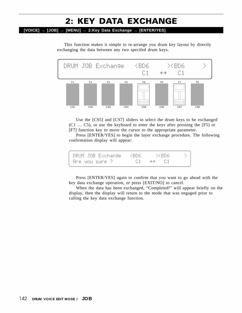
142 DRUM VOICE EDIT MODE / JOB
This function makes it simple to re-arrange you drum key layout by directlyexchanging the data between any two specifed drum keys.
Use the [CS5] and [CS7] sliders to select the drum keys to be exchanged(C1 … C5), or use the keyboard to enter the keys after pressing the [F5] or[F7] function key to move the cursor to the appropriate parameter.
Press [ENTER/YES] to begin the layer exchange procedure. The followingconfirmation display will appear:
DRUM`JOB`Exchange```<BD6`````><BD6`````>
Are`you`sure`?````````C1```†¥```C1
Press [ENTER/YES] again to confirm that you want to go ahead with thekey data exchange operation, or press [EXIT/NO] to cancel.
When the data has been exchanged, “Completed!” will appear briefly on thedisplay, then the display will return to the mode that was engaged prior tocalling the key data exchange function.
2: KEY DATA EXCHANGE[VOICE] → [JOB] → [MENU] → 2:Key Data Exchange → [ENTER/YES]
F1
CS1
F2
CS2
F3
CS3
F4
CS4
F5
CS5
F6
CS6
F7
CS7
F8
CS8
DRUM`JOB`Exchange```<BD6`````><BD6`````>
``````````````````````C1```†¥```C1``
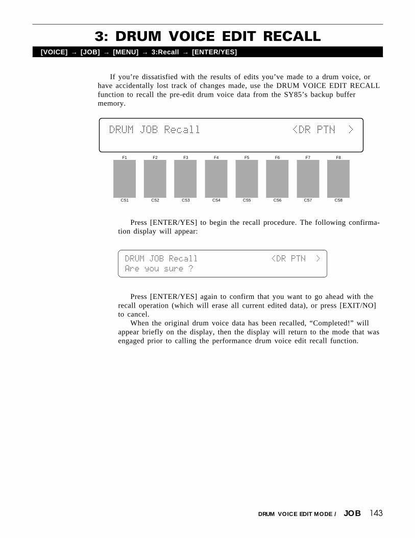
143DRUM VOICE EDIT MODE / JOB
3: DRUM VOICE EDIT RECALL[VOICE] → [JOB] → [MENU] → 3:Recall → [ENTER/YES]
If you’re dissatisfied with the results of edits you’ve made to a drum voice, orhave accidentally lost track of changes made, use the DRUM VOICE EDIT RECALLfunction to recall the pre-edit drum voice data from the SY85’s backup buffermemory.
Press [ENTER/YES] to begin the recall procedure. The following confirma-tion display will appear:
DRUM`JOB`Recall```````````````<DR`PTN``>
Are`you`sure`?
Press [ENTER/YES] again to confirm that you want to go ahead with therecall operation (which will erase all current edited data), or press [EXIT/NO]to cancel.
When the original drum voice data has been recalled, “Completed!” willappear briefly on the display, then the display will return to the mode that wasengaged prior to calling the performance drum voice edit recall function.
F1
CS1
F2
CS2
F3
CS3
F4
CS4
F5
CS5
F6
CS6
F7
CS7
F8
CS8
DRUM`JOB`Recall```````````````<DR`PTN``>
``

144
4: DRUM VOICE INITIALIZE[VOICE] → [JOB] → [MENU] → 2:Initialize → [ENTER/YES]
When you want to program a totally new drum voice “from scratch,” rather thanediting an existing voice, use this function to initialize all drum voice parameters.
Use [CS6] to select the type of drum voice to be initialized. Press [ENTER/YES] to begin the initialize procedure. The following confirmation display willappear:
DRUM`JOB`Initialize```````Type
Are`you`sure`?``````````````1
Press [ENTER/YES] again to confirm that you want to go ahead with theinitialize operation (which will erase all current edited data), or press [EXIT/NO] to cancel.
When the drum voice data has been initialized, “Completed!” will appearbriefly on the display, then the display will return to the mode that was en-gaged prior to calling the drum voice initialize function.
DRUM VOICE EDIT MODE / JOB
F1
CS1
F2
CS2
F3
CS3
F4
CS4
F5
CS5
F6
CS6
F7
CS7
F8
CS8
DRUM`JOB`Initialize```````Type
````````````````````````````1

145
DRUM VOICE COMPARE[SHIFT] + [STORE]
The drum voice compare function makes it possible to compare the sound of adrum voice being edited with the same drum voice prior to editing.
To temporarily recall the original drum voice data while editing, press the[STORE] key while holding the [SHIFT] key. The [VOICE] LED will flash, indicat-ing that the compare mode is engaged. Although you can select different edit modedisplay screens, data cannot be edited in the compare mode. Press [EXIT/NO] toreturn to the edit mode and the drum voice being edited.
DRUM VOICE EDIT MODE / COMPARE

146
DRUM VOICE STORE[STORE]
When you’re satisfied with a new drum voice you’ve created in the drum voiceedit mode, use the store function described below to store the new voice to an inter-nal or card memory location.
When you’ve finished editing, return to the normal play mode (press the[VOICE] key), and before selecting a different voice press the [STORE] key.You can now use the MEMORY, GROUP, and NUMBER keys to select thememory location to which your new drum voice is to be stored.
Once the store location has been specified, press [ENTER/YES] to beginthe store procedure. The following confirmation display will appear:
VOICE`STORE`(DRUM)```To
Are`you`sure`?```````¡H8:DR`PTN
Press [ENTER/YES] again to confirm that you want to go ahead with thestore operation (which will erase all previous data in the specified memorylocation), or press [EXIT/NO] to cancel.
When the voice data has been stored, “Completed!” will appear briefly onthe display, then the display will return to the mode that was engaged prior tocalling the store function.
DRUM VOICE EDIT MODE / STORE
F1
CS1
F2
CS2
F3
CS3
F4
CS4
F5
CS5
F6
CS6
F7
CS7
F8
CS8
VOICE`STORE`(DRUM)```To
`````````````````````¡H8:DR`PTN

SONG EDIT MODE

148 SONG EDIT MODE / MULTI EDIT
Each SY85 “song” has an independent “multi setup” that can have up to 16voices assigned to “instruments” 1 through 16. Each instrument is controlled via thecorrespondingly numbered MIDI channel. This screen lets you select the voices thatare to be played via the various multi-setup channels.
1: VOICE SELECT[SONG] → [MULTI EDIT] → [MENU] → 1:Voice Select → [ENTER/YES]
F1
CS1
F2
CS2
F3
CS3
F4
CS4
F5
CS5
F6
CS6
F7
CS7
F8
CS8
MULTI`Voice`Select`1-`8```````<InitPerf>
P¡A1`P¡A1`P¡A1`P¡A1`P¡A1`P¡A1`P¡A1`P¡A1`
Voice Select 1… 16Range: off, Any voice or performance combination.Controls: [SHIFT] + [ kkkkk]/[lllll], MEMORY, GROUP, PROGRAM, [CS1] …
[CS8], [-1] [+1], Dial
Only eight voice numbers are shown on the display at one time. Use thePAGE [k] and [l] keys while holding the [SHIFT] key to switch betweenmulti instruments “1 … 8” and “9 … 16”. The currenty selected group ofvoices is indicated on the upper display line.
After moving the cursor to the instrument you want to edit by pressing theappropriate function key, use the same function key to toggle between PER-FORMANCE or VOICE memory (“P” or “V” at the beginning of the voicenumber). Then use the [INTERNAL 1], [INTERNAL 2], and [CARD] keys toselect the memory area from which the voice is to be selected, and finally theGROUP and PROGRAM keys to select the voice. Voices within the selectedmemory bank can also be selected directy for each channel by the appropriateCS sliders, the data entry dial, and the [-] and [+] keys.
The voices can individually turned on or off by using the [-] (off) and [+](on) keys while holding the [SHIFT] key.
The name of the currently selected voice is shown in the upper right cornerof the display.

149
For optimum balance between the instruments in a multi setup, this screen allowsthe volume of each voice to be adjusted individually.
2: VOLUME[SONG] → [MULTI EDIT] → [MENU] → 2:Volume → [ENTER/YES]
VolumeRange: 0 … 127Controls: [SHIFT] + [ kkkkk]/[lllll], [CS1] … [CS8], [-1] [+1], Dial
Only eight voice numbers are shown on the display at one time. Use thePAGE [k] and [l] keys while holding the [SHIFT] key to switch betweenmulti instruments “1 … 8” and “9 … 16”. The currenty selected group ofvoices is indicated on the upper display line.
Use the [CS1] through [CS8] sliders to adjust the volume levels of voices 1through 8 or 9 through 16, respectively. The name of the currently selectedvoice is shown in the upper right corner of the display. Voices that are turnedoff are indicated by “---” on the display. A setting of “0” produces no sound,while a setting of “127” produces maximum volume. The vertical bar graphsnext to each parameter provide a visual indication of volume levels — thelonger the bar the higher the volume.
F1
CS1
F2
CS2
F3
CS3
F4
CS4
F5
CS5
F6
CS6
F7
CS7
F8
CS8
MULTI`Volume```````1-`8```````<InitPerf>
`127ƒ`127ƒ`127ƒ`127ƒ`127ƒ`127ƒ`127ƒ`127ƒ
SONG EDIT MODE / MULTI EDIT

150 SONG EDIT MODE / MULTI EDIT
In a multi setup, interesting stereo effects can be produced by placing the outputfrom different voices at different locations in the stereo sound field. The parametersin this screen determine the position in the stereo sound field in which the soundfrom each active voice will be heard (left to right).
3: PAN[SONG] → [MULTI EDIT] → [MENU] → 3:Pan → [ENTER/YES]
F1
CS1
F2
CS2
F3
CS3
F4
CS4
F5
CS5
F6
CS6
F7
CS7
F8
CS8
MULTI`Pan`L¯¯˘¯¯R`1-`8````````<InitPerf>
``+0```+0```+0```+0```+0```+0```+0```+0`
PanRange: -31 … +31, vceControls: [SHIFT] + [ kkkkk]/[lllll], [CS1] … [CS8], [-1] [+1], Dial
Only eight voice numbers are shown on the display at one time. Use thePAGE [k] and [l] keys while holding the [SHIFT] key to switch betweenmulti instruments “1 … 8” and “9 … 16”. The currenty selected group ofvoices is indicated on the upper display line.
Use the [CS1] through [CS8] sliders to adjust the pan positions of voices 1through 8 or 9 through 16, respectively. The name of the currently selectedvoice is shown in the upper right corner of the display. Voices that are turnedoff are indicated by “---” on the display. Minus values represent panning to theleft, and positive values represent panning to the right. “0” positions the soundof the selected layer in the center of the stereo sound field. The next settingabove “+31” is “vce.” When “vce” is selected the preset pan position for theselected voice or performance combination is used. The upper line of the dis-play also shows a graphic representation of the stereo sound field with “L”representing “left” and “R” representing “right.” As you change the pan valuethe vertical bar will appear at the corresponding position on the graphic dis-play.
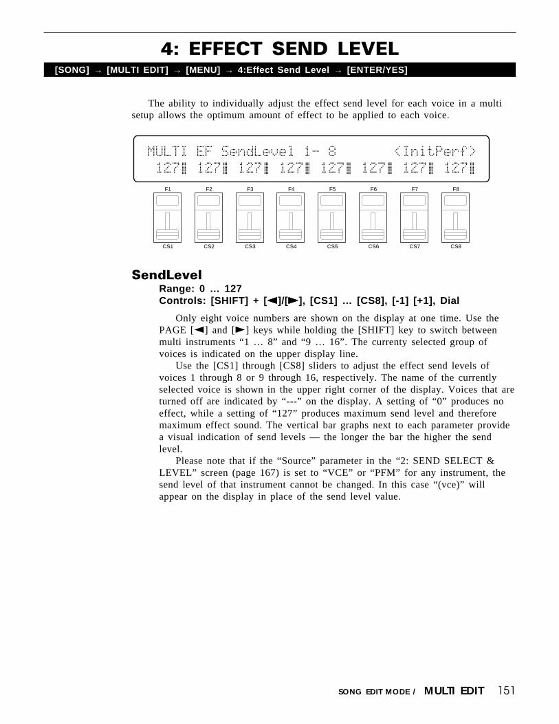
151SONG EDIT MODE / MULTI EDIT
The ability to individually adjust the effect send level for each voice in a multisetup allows the optimum amount of effect to be applied to each voice.
4: EFFECT SEND LEVEL[SONG] → [MULTI EDIT] → [MENU] → 4:Effect Send Level → [ENTER/YES]
SendLevelRange: 0 … 127Controls: [SHIFT] + [ kkkkk]/[lllll], [CS1] … [CS8], [-1] [+1], Dial
Only eight voice numbers are shown on the display at one time. Use thePAGE [k] and [l] keys while holding the [SHIFT] key to switch betweenmulti instruments “1 … 8” and “9 … 16”. The currenty selected group ofvoices is indicated on the upper display line.
Use the [CS1] through [CS8] sliders to adjust the effect send levels ofvoices 1 through 8 or 9 through 16, respectively. The name of the currentlyselected voice is shown in the upper right corner of the display. Voices that areturned off are indicated by “---” on the display. A setting of “0” produces noeffect, while a setting of “127” produces maximum send level and thereforemaximum effect sound. The vertical bar graphs next to each parameter providea visual indication of send levels — the longer the bar the higher the sendlevel.
Please note that if the “Source” parameter in the “2: SEND SELECT &LEVEL” screen (page 167) is set to “VCE” or “PFM” for any instrument, thesend level of that instrument cannot be changed. In this case “(vce)” willappear on the display in place of the send level value.
F1
CS1
F2
CS2
F3
CS3
F4
CS4
F5
CS5
F6
CS6
F7
CS7
F8
CS8
MULTI`EF`SendLevel`1-`8```````<InitPerf>
`127ƒ`127ƒ`127ƒ`127ƒ`127ƒ`127ƒ`127ƒ`127ƒ

152 SONG EDIT MODE / MULTI EDIT
Individually shifts the pitch of each active voice up or down in semitone steps.
5: NOTE SHIFT[SONG] → [MULTI EDIT] → [MENU] → 5:Note Shift → [ENTER/YES]
F1
CS1
F2
CS2
F3
CS3
F4
CS4
F5
CS5
F6
CS6
F7
CS7
F8
CS8
MULTI`Note`Shift```1-`8```````<InitPerf>
``+0```+0```+0```+0```+0```+0```+0```+0`
Note ShiftRange: -63 … +63Controls: [SHIFT] + [ kkkkk]/[lllll], [CS1] … [CS8], [-1] [+1], Dial
Only eight voice numbers are shown on the display at one time. Use thePAGE [k] and [l] keys while holding the [SHIFT] key to switch betweenmulti instruments “1 … 8” and “9 … 16”. The currenty selected group ofvoices is indicated on the upper display line.
Use the [CS1] through [CS8] sliders to shift the pitch of voices 1 through 8or 9 through 16, respectively. The name of the currently selected voice isshown in the upper right corner of the display. Voices that are turned off areindicated by “---” on the display. A setting of “-12,” for example, shifts thepitch of the selected layer down by one octave; a setting of “+4” shifts thepitch up by a major third. Please note that note shift cannot be applied todrum/percussion voices (the Note Shift value is fixed at “+0”).
The Note Shift parameter can be used to transpose a voice to its mostuseful range, or to create harmony (intervals) between different voices in amulti setup.

153SONG EDIT MODE / MULTI EDIT
Allows slight upward or downward pitch adjustment of each active voice. Morethan just simple tuning, the tune parameters make it possible to create sound-thicken-ing detune effects between voices.
6: TUNE[SONG] → [MULTI EDIT] → [MENU] → 6:Tune → [ENTER/YES]
Tune (Fine tuning)Range: -63 … +63Controls: [SHIFT] + [ kkkkk]/[lllll], [CS1] … [CS8], [-1] [+1], Dial
Only eight voice numbers are shown on the display at one time. Use thePAGE [k] and [l] keys while holding the [SHIFT] key to switch betweenmulti instruments “1 … 8” and “9 … 16”. The currenty selected group ofvoices is indicated on the upper display line.
Use the [CS1] through [CS8] sliders to fine tune voices 1 through 8 or 9through 16, respectively. The name of the currently selected voice is shown inthe upper right corner of the display. Voices that are turned off are indicatedby “---” on the display. Each increment corresponds to approximately 1.17cents (a “cent” is 1/100th of a semitone). The maximum minus setting of “-63”produces a downward pitch shift of almost three-quarters of a semitone, and themaximum plus setting of “+63” produces an upward pitch shift of the sameamount. A setting of “0” produces no pitch change. Please note that tuningcannot be applied to drum/percussion voices (the Tune value is fixed at “+0”).
F1
CS1
F2
CS2
F3
CS3
F4
CS4
F5
CS5
F6
CS6
F7
CS7
F8
CS8
MULTI`Tune`````````1-`8```````<InitPerf>
``+0```+0```+0```+0```+0```+0```+0```+0`

154 SONG EDIT MODE / MULTI EDIT
The SY85 features a complex, high-performance effect system that can be pro-grammed easily via the parameters presented here and in the following screen.
For a complete list of effect parameters see page 274.
7: EFFECT TYPE, OUT BALANCE[SONG] → [MULTI EDIT] → [MENU] → 7:Effect Type → [ENTER/YES]
F1
CS1
F2
CS2
F3
CS3
F4
CS4
F5
CS5
F6
CS6
F7
CS7
F8
CS8
MULTI`````Effect`Type````````Wet`Balance
``06:Rev.Stagel``57:EQ`->`Sym```50%``50%
Effect Type 1/2Range: 0 … 90Controls: [CS1]/[CS4], [-1] [+1], Dial
[CS1] selects any of the SY85’s 90 effect types for the EFFECT 1 proces-sor, and [CS4] does the same for the EFFECT 2 processor. See page 254 formore details on the SY85 effect system.
Wet Balance 1/2Range: 0 … 100Controls: [CS7]/[CS8], [-1] [+1], Dial
[CS7] controls the balance between the direct no-effect sound and the effectsound of the EFFECT 1 processor, while [CS8] does the same for the EFFECT2 processor. The higher the value the deeper the effect. See page 254 for moredetails on the SY85 effect system.

155SONG EDIT MODE / MULTI EDIT
Your original songs should naturally have original names. This function can beused to assign a name of up to 8 characters to the current song.
8: SONG NAME[SONG] → [MULTI EDIT] → [MENU] → 8:Name → [ENTER/YES]
NameRange: See character list, belowControls: GROUP, PROGRAM, [F1] … [F4], [F7], [F8],
[CS1] … [CS8], [-1] [+1], Dial
Assigns a name of up to 8 characters to the current performance.Use the [F7] function key to move the character cursor to the left, and the
[F8] function key to move the cursor to the right. Use the GROUP and PRO-GRAM keys to input a character at the cursor position. Each GROUP or PRO-GRAM key selects the three characters printed above it in sequence. It is alsopossible to use the [-1] and [+1] keys or dial to scroll through the availablecharacters (see list below).
The sliders, [CS1] through [CS8], independently select characters for thecorresponding character position: [CS1] selects the first character, [CS2] selectsthe second character, and so on.
The first four function keys also perform important functions: [F1] clearsthe entire name, [F2] selects upper-case characters for GROUP and PROGRAMkey entry, [F3] selects lower-case characters for GROUP and PROGRAM keyentry, and [F4] inserts a space at the cursor position.
F1
CS1
F2
CS2
F3
CS3
F4
CS4
F5
CS5
F6
CS6
F7
CS7
F8
CS8
MULTI`Song`Name```````````````"InitSong"
[CLR][UPR][LWR][SPC]````````````[†]``[¥]
[A]: A → B → C[B]: D → E → F[C]: G → H → I[D]: J → K → L[E]: M → N → O[F]: P → Q → R[G]: S → T → U[H]: V → W → X
[1]: Y → Z → 0[2]: 1 → 2 → 3[3]: 4 → 5 → 6[4]: 7 → 8 → 9[5]: * → & → _[6]: / → . → ,[7]: ’ → ! → ?[8]: # → : → ;
PROGRAM keyGROUP key

156 SONG EDIT MODE / MULTI EDIT
When you want to program a totally new multi setup “from scratch,” rather thanediting an existing setup, use this function to initialize all multi parameters.
9: SONG INITIALIZE[SONG] → [MULTI EDIT] → [MENU] → 9:Initialize → [ENTER/YES]
F1
CS1
F2
CS2
F3
CS3
F4
CS4
F5
CS5
F6
CS6
F7
CS7
F8
CS8
MULTI`Initialize``````````````"InitSong"
````````````````````````````````````````
Press [ENTER/YES] to begin the initialize procedure. The following confir-mation display will appear:
MULTI`Initialize``````````````"InitSong"
Are`you`sure`?``````````````````````````
Press [ENTER/YES] again to confirm that you want to go ahead with theinitialize operation (which will erase all current edited data), or press [EXIT/NO] to cancel.
When the multi data has been initialized, “Completed!” will appear brieflyon the display, then the display will return to the mode that was engaged priorto calling the multi initialize function.

157SONG EDIT MODE / TRACK EDIT
TRACK EDIT[SONG] → [TRACK EDIT] → [A]~[H]
The track edit mode has two sub-modes — change and insert — which willbe described below. Use the [F1] key to toggle between the change (“CHG” onthe display) and insert (“INS” on the display) modes. The change mode isalways selected when the track edit mode is initially engaged.
`````Meas`Beat`Clock`C#3```(›)``mf```````
`CHG``001`-`01`-`24```61`0018```64`ERASE
F1
CS1
F2
CS2
F3
CS3
F4
CS4
F5
CS5
F6
CS6
F7
CS7
F8
CS8
The track edit mode is used to edit material already recorded on the sequencertracks. Individual notes and other events can be deleted, changed, or inserted asrequired, providing precise musical control.
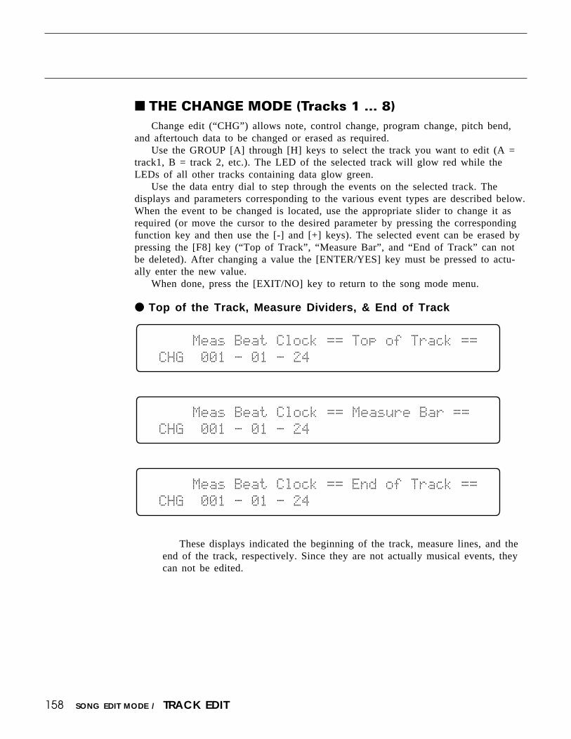
158 SONG EDIT MODE / TRACK EDIT
THE CHANGE MODE (Tracks 1 … 8)Change edit (“CHG”) allows note, control change, program change, pitch bend,
and aftertouch data to be changed or erased as required.Use the GROUP [A] through [H] keys to select the track you want to edit (A =
track1, B = track 2, etc.). The LED of the selected track will glow red while theLEDs of all other tracks containing data glow green.
Use the data entry dial to step through the events on the selected track. Thedisplays and parameters corresponding to the various event types are described below.When the event to be changed is located, use the appropriate slider to change it asrequired (or move the cursor to the desired parameter by pressing the correspondingfunction key and then use the [-] and [+] keys). The selected event can be erased bypressing the [F8] key (“Top of Track”, “Measure Bar”, and “End of Track” can notbe deleted). After changing a value the [ENTER/YES] key must be pressed to actu-ally enter the new value.
When done, press the [EXIT/NO] key to return to the song mode menu.
Top of the Track, Measure Dividers, & End of Track
`````Meas`Beat`Clock`==`Top`of`Track`==``
`CHG``001`-`01`-`24`````````````````````
`````Meas`Beat`Clock`==`Measure`Bar`==``
`CHG``001`-`01`-`24`````````````````````
`````Meas`Beat`Clock`==`End`of`Track`==``
`CHG``001`-`01`-`24`````````````````````
These displays indicated the beginning of the track, measure lines, and theend of the track, respectively. Since they are not actually musical events, theycan not be edited.
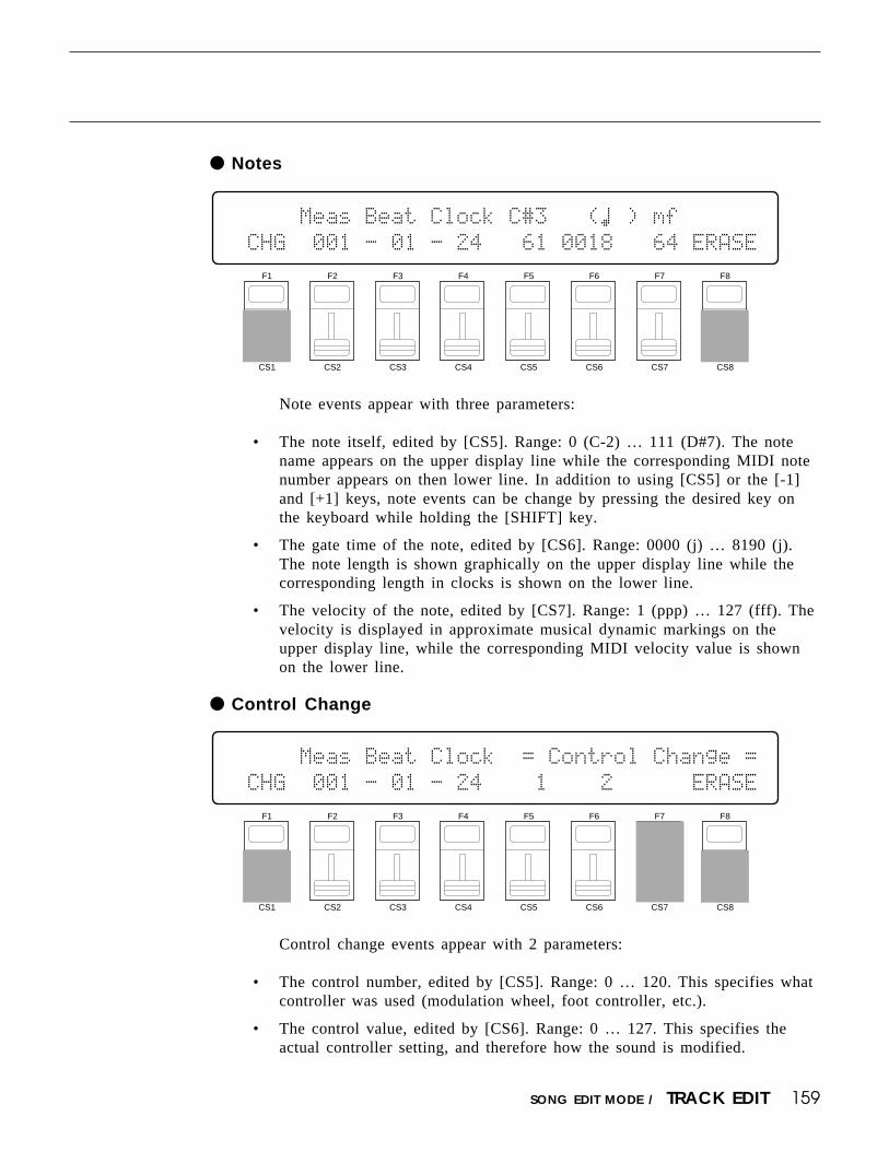
159SONG EDIT MODE / TRACK EDIT
Notes
Note events appear with three parameters:
• The note itself, edited by [CS5]. Range: 0 (C-2) … 111 (D#7). The notename appears on the upper display line while the corresponding MIDI notenumber appears on then lower line. In addition to using [CS5] or the [-1]and [+1] keys, note events can be change by pressing the desired key onthe keyboard while holding the [SHIFT] key.
• The gate time of the note, edited by [CS6]. Range: 0000 (j) … 8190 (j).The note length is shown graphically on the upper display line while thecorresponding length in clocks is shown on the lower line.
• The velocity of the note, edited by [CS7]. Range: 1 (ppp) … 127 (fff). Thevelocity is displayed in approximate musical dynamic markings on theupper display line, while the corresponding MIDI velocity value is shownon the lower line.
Control Change
`````Meas`Beat`Clock`C#3```(›`)`mf```````
`CHG``001`-`01`-`24```61`0018```64`ERASE
F1
CS1
F2
CS2
F3
CS3
F4
CS4
F5
CS5
F6
CS6
F7
CS7
F8
CS8
F1
CS1
F2
CS2
F3
CS3
F4
CS4
F5
CS5
F6
CS6
F7
CS7
F8
CS8
`````Meas`Beat`Clock``=`Control`Change`=
`CHG``001`-`01`-`24````1````2``````ERASE
Control change events appear with 2 parameters:
• The control number, edited by [CS5]. Range: 0 … 120. This specifies whatcontroller was used (modulation wheel, foot controller, etc.).
• The control value, edited by [CS6]. Range: 0 … 127. This specifies theactual controller setting, and therefore how the sound is modified.

160
Program Change
SONG EDIT MODE / TRACK EDIT
Pitch change events appear with a single parameter: the new pitch bendvalue, edited via [CS6]. Range: -64 … +63.
Aftertouch
Program change events have a single parameter: the program changenumber itself, edited via [CS6]. Range: 000 … 127. Program change numbersnormally specify a voice change.
Pitch Bend
Aftertouch events appear with a single parameter: the new aftertouch value,edited via [CS6]. Range: 0 … 127. The effect of aftertouch events depends onhow aftertouch control is assigned in the voice edit mode.
F1
CS1
F2
CS2
F3
CS3
F4
CS4
F5
CS5
F6
CS6
F7
CS7
F8
CS8
`````Meas`Beat`Clock``=`Program`Change`=
`CHG``001`-`01`-`24```````001``````ERASE
F1
CS1
F2
CS2
F3
CS3
F4
CS4
F5
CS5
F6
CS6
F7
CS7
F8
CS8
`````Meas`Beat`Clock``=`Pitch`Bend`=````
`CHG``001`-`01`-`24```````+07``````ERASE
F1
CS1
F2
CS2
F3
CS3
F4
CS4
F5
CS5
F6
CS6
F7
CS7
F8
CS8
`````Meas`Beat`Clock``=`After`Touch`=```
`CHG``001`-`01`-`24`````````7``````ERASE

161SONG EDIT MODE / TRACK EDIT
The Meas, Beat, and Clock Parameters
These three parameters are common to all the displays described above. Inaddition to indicating the location of the current event, they can be edited tomove the event as required:
• The “Meas” parameter, edited via [CS2], indicates the number of the cur-rent measure. Range: 001 … 999. The length of each measure depends onthe time signature of the song.
• The “Beat” parameter, edited via [CS3], indicates the current beat withinthe current measure. The value of each beat and the number of beats ineach measure depend on the selected time signature. If the time signature is4/4, for example, each beat will equal one quarter-note, and there will befour beats per measure. If the time signature is 6/8, however, each beat willequal an eighth-note, and there will be six beats per measure.
• The “Clock” parameter, edited via [CS4], indicates the current clock withinthe current beat within the current measure. There are 48 clocks per quarternote, 24 per eighth note, 12 per sixteenth note, and so on.
If the “Top of Track”, “Measure Bar”, or “End of Track” display is show-ing, changing these parameters and pressing the [ENTER/YES] key takes youdirectly to the specified location.
THE INSERT MODE (Tracks 1 … 8)Insert edit (INS) allows note, control change, program change, pitch bend, and
aftertouch events to be inserted at any point in the sequencer tracks.Normally, the insert mode is entered by pressing the [F1] key after locating the
desired insert point in the change mode. The type of event to be inserted can then beselected by pressing the [F8] key until the desired event appears on the display(“NOTE” = note; “CTRL” = control change; “PGM” = program change; “PB” = pitchbend; “AT” = aftertouch). The various event types have the same parameters andranges as in the change mode (see above). Set the parameters for the selected eventas required, then press the [ENTER/YES] key to insert the event.
The insert location can be changed while in the insert mode by using the dataentry dial. The [F3] key determines whether the dial changes the measure (“MEAS”),beat (“BEAT”), or clock (“CLOCK”) value.
Press the [F1] key to return to the change mode, or the [EXIT/NO] key to returnto the song play mode.
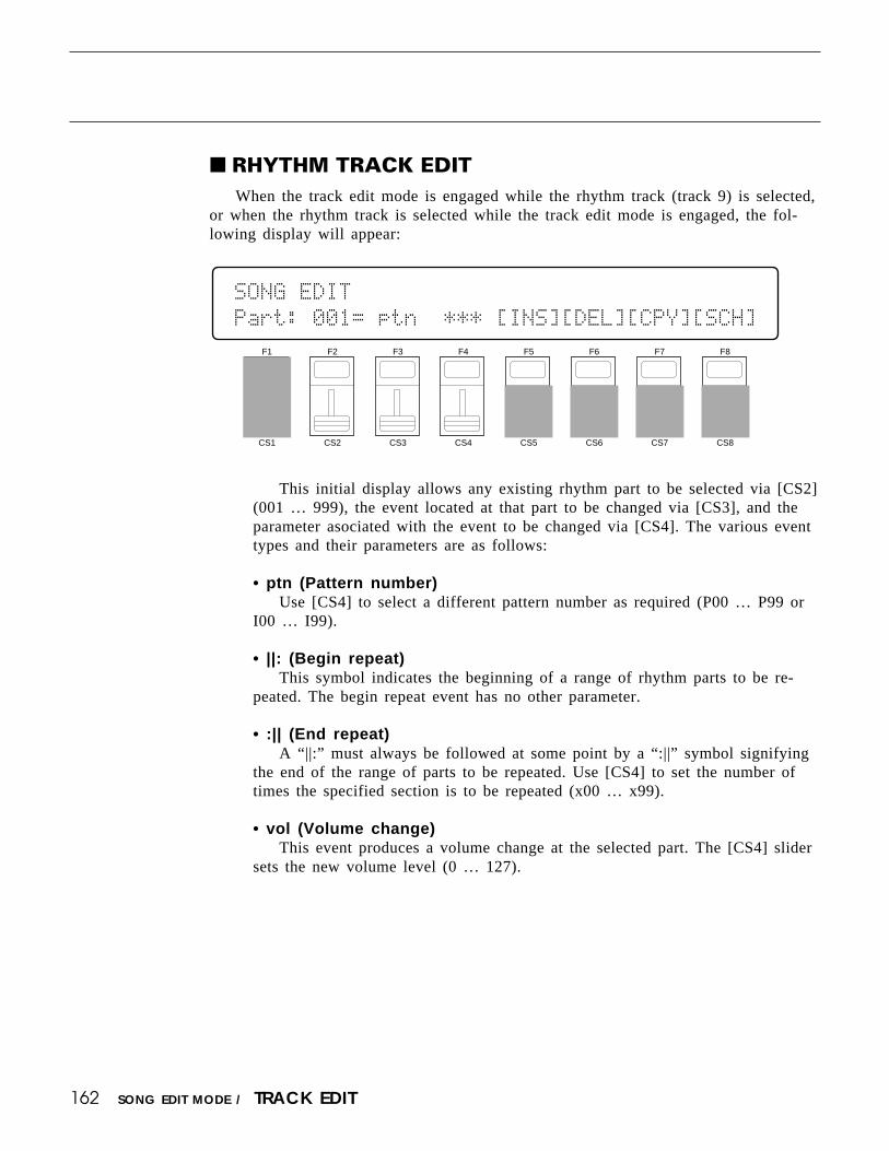
162 SONG EDIT MODE / TRACK EDIT
This initial display allows any existing rhythm part to be selected via [CS2](001 … 999), the event located at that part to be changed via [CS3], and theparameter asociated with the event to be changed via [CS4]. The various eventtypes and their parameters are as follows:
• ptn (Pattern number)Use [CS4] to select a different pattern number as required (P00 … P99 or
I00 … I99).
• ||: (Begin repeat)This symbol indicates the beginning of a range of rhythm parts to be re-
peated. The begin repeat event has no other parameter.
• :|| (End repeat)A “||:” must always be followed at some point by a “:||” symbol signifying
the end of the range of parts to be repeated. Use [CS4] to set the number oftimes the specified section is to be repeated (x00 … x99).
• vol (Volume change)This event produces a volume change at the selected part. The [CS4] slider
sets the new volume level (0 … 127).
F1
CS1
F2
CS2
F3
CS3
F4
CS4
F5
CS5
F6
CS6
F7
CS7
F8
CS8
SONG`EDIT```````````````````````````````
Part:`001=`ptn``***`[INS][DEL][CPY][SCH]
RHYTHM TRACK EDITWhen the track edit mode is engaged while the rhythm track (track 9) is selected,
or when the rhythm track is selected while the track edit mode is engaged, the fol-lowing display will appear:

163SONG EDIT MODE / TRACK EDIT
• tmp (Tempo change)This event indicates a tempo change to occur over a specified number of
beats. The numbers above the [CS4] slider define the tempo change: thenumber to the left of the slash (-99 … 0 … +99, or atmp for “a tempo”) setsthe number of beats per minute by which the tempo will decrease or increase,and the number to the right of the slash (0 … 99) sets the number of beatsfrom the “tmp” mark over which the change will occur. A setting of “+20/8”,for example, would increase the tempo by 20 beats per minute over 8 beats (2measures of 4/4 time). The [F4] function key is used to toggle the cursorbetween the left and right numbers, and [CS4] is used to change the selectednumber.
• mark (Search mark)This sets one of 16 markers to be used by the rhythm track search function
described on page 165. [CS4] is used to specify the marker (A … P).
The [F5] through [F8] function keys are used to access the rhythm trackedit functions described below:
[F5]: “INS” = Rhythm Track Insert
F1
CS1
F2
CS2
F3
CS3
F4
CS4
F5
CS5
F6
CS6
F7
CS7
F8
CS8
SONG`EDIT`Insert`Part```````````````````
`Part:001=`ptn``***`````````````````````
This function is used to insert a new part at any point in an existing rhythmtrack. Press [F5] to engage the rhythm track insert function after locating thedesired insert point via the main rhythm track edit screen, described above.Then use [CS3] and [CS4] to specify the event to be inserted. The event typesthat can be inserted and their parameters are exactly the same as those de-scribed for the main rhythm track edit screen, above. Once the event to beinserted has been specified, press [ENTER/YES] to begin the insert procedure.The following confirmation display will appear:
SONG`EDIT`Insert`Part`````Are`you`sure`?
`Part:001=`ptn``***`````````````````````
Press [ENTER/YES] again to confirm that you want to go ahead with theinsert operation, or press [EXIT/NO] to cancel.
When the event has been inserted, “Completed!” will appear briefly on thedisplay, then the display will return to the main rhythm track edit mode.

164 SONG EDIT MODE / TRACK EDIT
[F6]: “DEL” = Rhythm Track Delete
F1
CS1
F2
CS2
F3
CS3
F4
CS4
F5
CS5
F6
CS6
F7
CS7
F8
CS8
SONG`EDIT`Delete`Part```````````````````
`Part:001=`ptn``***`````````````````````
This function is used to delete a part from an existing rhythm track. Press[F6] to engage the rhythm track delete function after locating the part to bedeleted via the main rhythm track edit screen, described above. The followingconfirmation display will appear:
SONG`EDIT`Delete`Part`````Are`you`sure`?
`Part:001=`ptn``***`````````````````````
Press [ENTER/YES] again to confirm that you want to go ahead with thedelete operation, or press [EXIT/NO] to cancel.
When the part has been deleted, “Completed!” will appear briefly on thedisplay, then the display will return to the main rhythm track edit mode.
[F7]: “CPY” = Rhythm Track Copy
F1
CS1
F2
CS2
F3
CS3
F4
CS4
F5
CS5
F6
CS6
F7
CS7
F8
CS8
SONG`EDIT`Copy`Part```````from``````To``
`Part:001=`ptn``***```````001ø`001``001`
This function is used to copy a part or a range of parts to any other pointin a rhythm track. Press [F7] to engage the rhythm track copy function. Thenuse [CS6] to select the number of the first part in the range of parts to becopied (001 … 999), [CS7] to select the number of the last part in the range ofparts to be copied (001 … 999), and [CS8] to select the part number to whichthe source parts will be copied (001 … 999). Press [ENTER/YES] to begin thecopy procedure. The following confirmation display will appear:

165SONG EDIT MODE / TRACK EDIT
SONG`EDIT`Copy`Part```````Are`you`sure`?
`Part:001=`ptn``***```````001ø`001``001`
Press [ENTER/YES] again to confirm that you want to go ahead with thecopy operation (which will overwite existing parts from the destination partnumber), or press [EXIT/NO] to cancel.
When the parts have been copied, “Completed!” will appear briefly on thedisplay, then the display will return to the main rhythm track edit mode.
[F8]: “SCH” = Rhythm Track Search
This function makes it possible to directly locate “marks” entered in thetrack using the “mark” event in the main rhythm track edit screen. The[SHIFT] key is used to toggle between marks A through H and I through G.Square brackets appear around marks that exist within the rhythm track. To godirectly to a marked location, simply press the function key immediately belowthe desired mark. The main rhythm track edit screen will appear with themarked part selected.
If you select a mark that has not been specified, “Mark Not Used!” willappear on the display. Press [EXIT/No] to return to the Search Mark display.
F1
CS1
F2
CS2
F3
CS3
F4
CS4
F5
CS5
F6
CS6
F7
CS7
F8
CS8
SONG`EDIT`Search`Mark```````````````````
```A````B````C````D````E````F````G````H`
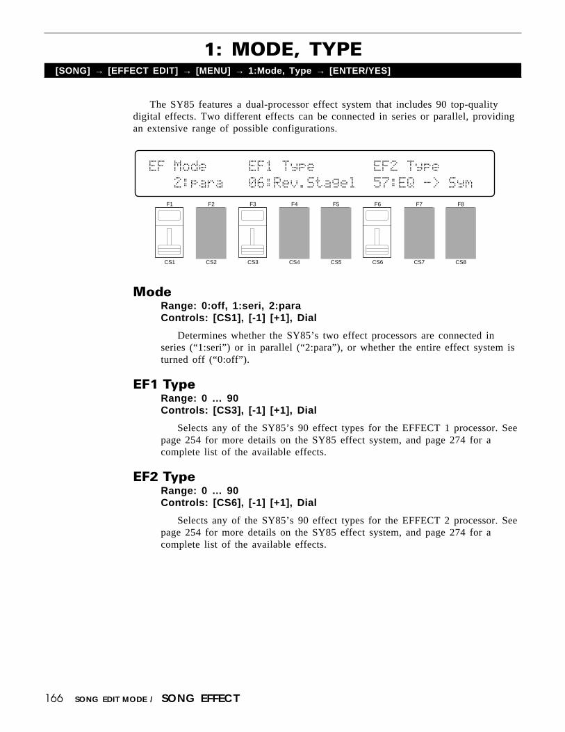
166 SONG EDIT MODE / SONG EFFECT
The SY85 features a dual-processor effect system that includes 90 top-qualitydigital effects. Two different effects can be connected in series or parallel, providingan extensive range of possible configurations.
1: MODE, TYPE[SONG] → [EFFECT EDIT] → [MENU] → 1:Mode, Type → [ENTER/YES]
F1
CS1
F2
CS2
F3
CS3
F4
CS4
F5
CS5
F6
CS6
F7
CS7
F8
CS8
EF`Mode`````EF1`Type```````EF2`Type`````
```2:para```06:Rev.Stagel``57:EQ`->`Sym`
ModeRange: 0:off, 1:seri, 2:paraControls: [CS1], [-1] [+1], Dial
Determines whether the SY85’s two effect processors are connected inseries (“1:seri”) or in parallel (“2:para”), or whether the entire effect system isturned off (“0:off”).
EF1 TypeRange: 0 … 90Controls: [CS3], [-1] [+1], Dial
Selects any of the SY85’s 90 effect types for the EFFECT 1 processor. Seepage 254 for more details on the SY85 effect system, and page 274 for acomplete list of the available effects.
EF2 TypeRange: 0 … 90Controls: [CS6], [-1] [+1], Dial
Selects any of the SY85’s 90 effect types for the EFFECT 2 processor. Seepage 254 for more details on the SY85 effect system, and page 274 for acomplete list of the available effects.

167SONG EDIT MODE / SONG EFFECT
The parameters provided here determine to which of the SY85 effect stages theoutput from the voice assigned to each layer is sent, and at what level. It is alsopossible to control the effect send level via keyboard dynamics and key scaling.
2: SEND SELECT & LEVEL[SONG] → [EFFECT EDIT] → [MENU] → 2:Send → [ENTER/YES]
Inst (Instrument)Range: 1 … 16Controls: [CS2], [-1] [+1], Dial
Selects the multi instrument to be edited. The name of the voice assigned tothe selected instrument is shown between parentheses on the upper line of thedisplay.
SourceRange: MLT, VCE, PFMControls: [CS5], [-1] [+1], Dial
When “MLT” is selected the “Switch” and “Levl” parameters, describedbelow, can be applied to the selected instrument. If a voice is assigned to theselected instrument, the “Source” parameter can also be set to “VCE”, causingthe switch and send levels of the assigned voice to be used. In the same way,if a performance combination is assigned to the selected instrument, the“Source” parameter can be set to “PFM”, causing the switch and send levels ofthe assigned performance combination to be used. If “VCE” or “PFM” is se-lected, the “Switch” and “Levl” parameters cannot be edited (“----” appears inplace of the parameters).
Switch 1a, 1b/2a, 2bRange: See text below.Controls: [CS6]/[CS7], [-1] [+1], Dial
Determines to which of the EFFECT 1 and EFFECT 2 effect stages theoutput from the current layer is sent. Each time the [F6] or [F7] function key ispressed, the cursor alternately moves to the corresponding “a” or “b” parameter.The [-1] and [+1] keys can then be used to turn the stage on (“a” or “b”) oroff (“.”). The [CS6] and [CS7] sliders select the following settings in sequence:
F1
CS1
F2
CS2
F3
CS3
F4
CS4
F5
CS5
F6
CS6
F7
CS7
F8
CS8
EF`Send<InitSong>`Source``Switch````Levl
``Inst=`1(P¡A1)``````MLT``1a/-`2a/b``127

168 SONG EDIT MODE / SONG EFFECT
CS6 (EFFECT 1) CS7 (EFFECT 2)
1./. (a and b off) 2./. (a and b off)1a/. (a on, b off) 2a/. (a on, b off)1a/b (a and b on) 2a/b (a and b on)1./b (a off, b on) 2./b (a off, b on)
If a “single” type effect is selected then only stage “a” can be selected. If a“cascade” type effect is selected, then only stage “b” can be selected. If a“dual” type effect is selected, then both stages “a” and “b” can be selected. Aneffect stage that cannot be selected is represented by “-” on the display.
Levl (Send level)Range: 0 … 127Controls: [CS8], [-1] [+1], Dial
This parameter adjusts the amount of direct voice signal that is sent to theeffect processors, determining the strength of the final effect sound. A settingof “0” results in no effect, leaving only the “dry” sound. The maximum settingof “127” produces the maximum amount of effect.

169SONG EDIT MODE / SONG EFFECT
3: INST DRY OUTPUT SELECT[SONG] → [EFFECT EDIT] → [MENU] → 3:Inst Dry Out Select → [ENTER/YES]
Inst (Instrument)Range: 1 … 16Controls: [CS2], [-1] [+1], Dial
Selects the multi instrument to be edited. The name of the voice assigned tothe selected instrument is shown between parentheses on the upper line of thedisplay.
Dry1Range: off, onControls: [CS6], [-1] [+1], Dial
Turns the “dry line” bypassing the EFFECT 1 signal processor on or off.When this parameter is turned “off,” the “WET:DRY BALANCE” parameters(page 171) have no effect.
Dry2Range: off, onControls: [CS7], [-1] [+1], Dial
Turns the “dry line” bypassing the EFFECT 2 signal processor on or off.When this parameter is turned “off,” the “WET:DRY BALANCE” parameters(page 171) have no effect.
F1
CS1
F2
CS2
F3
CS3
F4
CS4
F5
CS5
F6
CS6
F7
CS7
F8
CS8
OUTPUT`Select`<InitSong>`Dry1`Dry2``````
``Inst=`1(P¡A1)````````````on```on``````

170 SONG EDIT MODE / SONG EFFECT
Depending on the selected effects the SY85 effect system can have up to fourseparate output levels that are adjusted by the parameters provided in this screen.
4: OUTPUT LEVEL[SONG] → [EFFECT EDIT] → [MENU] → 4:Output Level → [ENTER/YES]
F1
CS1
F2
CS2
F3
CS3
F4
CS4
F5
CS5
F6
CS6
F7
CS7
F8
CS8
EF`OutLevel`1a```1b`````````````2a```2b`
`EF1(sngl)=100%``--``EF2(casc)=`--``100%
1a, 1b, 2a, and 2b (Effect output levels)Range: 0 … 100Controls: [CS3], [CS4], [CS7], [CS8], [-1] [+1], Dial
The [CS3] and [CS4] sliders adjust the output levels of the effect 1 “1a”and “1b” stages, respectively, while the [CS7] and [CS8] sliders adjust theoutput levels of the effect 2 “2a” and “2b” stages. A setting of “0” turns outputfrom the corresponding effect stage off, while a setting of “100” producesmaximum output level.
If the selected effect is a “single” type, then only the “1a” or “2a” outputlevel is available. If it is a “cascade” type, then only the “1b” or “2b” outputlevel is available. Both the “1a” and “1b” or “2a” and “2b” levels are availableonly if the selected effect is a “dual” type. The type of the effects currentlyselected for the effect 1 and effect 2 processors are shown in parentheses onthe bottom line of the display. See page 254 for details on the effect stages andthe SY85 effect system in general.
If a controller is assigned to any of the output level parameters (page 174),an inverse “c” will appear to the right of the parameter.

171SONG EDIT MODE / SONG EFFECT
The balance between the direct sound of the voice and the effect sound is adelicate thing. Even slight changes can make a big difference to the final sound. Theparameters provided in this screen provide precise balance control.
5: WET:DRY BALANCE[SONG] → [EFFECT EDIT] → [MENU] → 5:Wet:Dry Balance → [ENTER/YES]
Out1 Wet/Out2 WetRange: 0 … 100Controls: [CS3]/[CS7], [-1] [+1], Dial
These parameters and the corresponding “Out1 Dry” and “Out2 Dry” pa-rameters, below, work together to balance the effect (“wet”) and direct (“dry”)signals delivered via the EFFECT 1 and EFFECT2 processors. Higher “Wet”values produce more effect sound in relation to the direct, dry sound of thevoice.
Although the “Wet” and “Dry” parameters can be set independently, adjust-ing one will cause the other to change so that their total is always 100(%).
If a controller is assigned to the “Out1 Wet” or “Out2 Wet” parameter(page 174), an inverse “c” will appear to the right of the parameter.
Out1 Dry/Out2 DryRange: 0 … 100Controls: [CS4]/[CS8], [-1] [+1], Dial
These parameters and the corresponding “Out1 Wet” and “Out2 Wet” pa-rameters, above, work together to balance the effect (“wet”) and direct (“dry”)signals delivered via the EFFECT 1 and EFFECT 2 processors, respectively.Higher “Dry” values produce more direct, dry sound in relation to the effectsound.
Although the “Wet” and “Dry” parameters can be set independently, adjust-ing one will cause the other to change so that their total is always 100(%).
If a controller is assigned to the “Out1 Dry” or “Out2 Dry” parameter (page174), an inverse “c” will appear to the right of the parameter.
F1
CS1
F2
CS2
F3
CS3
F4
CS4
F5
CS5
F6
CS6
F7
CS7
F8
CS8
EF`Wet:Dry`Balance``````````````````````
`````Out1=``50`:`50``````Out2=``50`:`50`
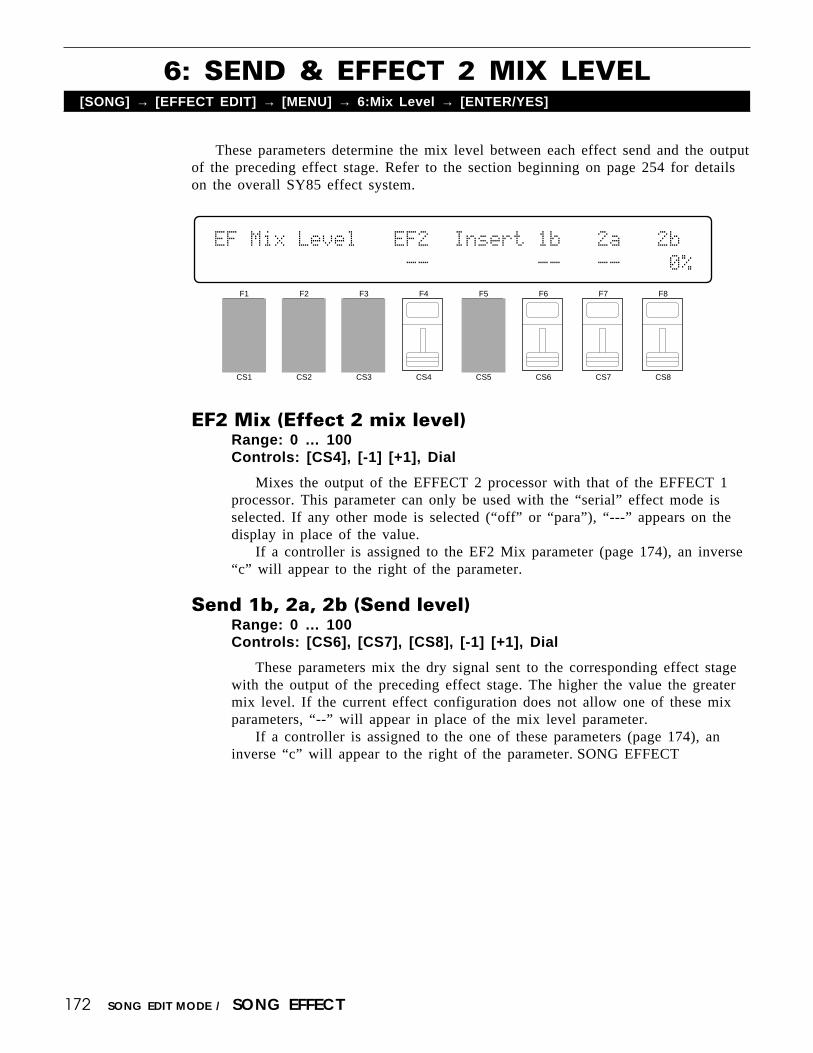
172 SONG EDIT MODE / SONG EFFECT
These parameters determine the mix level between each effect send and the outputof the preceding effect stage. Refer to the section beginning on page 254 for detailson the overall SY85 effect system.
6: SEND & EFFECT 2 MIX LEVEL[SONG] → [EFFECT EDIT] → [MENU] → 6:Mix Level → [ENTER/YES]
F1
CS1
F2
CS2
F3
CS3
F4
CS4
F5
CS5
F6
CS6
F7
CS7
F8
CS8
EF`Mix`Level```EF2``Insert`1b```2a```2b`
````````````````--`````````--```--````0%
EF2 Mix (Effect 2 mix level)Range: 0 … 100Controls: [CS4], [-1] [+1], Dial
Mixes the output of the EFFECT 2 processor with that of the EFFECT 1processor. This parameter can only be used with the “serial” effect mode isselected. If any other mode is selected (“off” or “para”), “---” appears on thedisplay in place of the value.
If a controller is assigned to the EF2 Mix parameter (page 174), an inverse“c” will appear to the right of the parameter.
Send 1b, 2a, 2b (Send level)Range: 0 … 100Controls: [CS6], [CS7], [CS8], [-1] [+1], Dial
These parameters mix the dry signal sent to the corresponding effect stagewith the output of the preceding effect stage. The higher the value the greatermix level. If the current effect configuration does not allow one of these mixparameters, “--” will appear in place of the mix level parameter.
If a controller is assigned to the one of these parameters (page 174), aninverse “c” will appear to the right of the parameter. SONG EFFECT
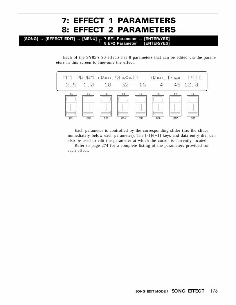
173SONG EDIT MODE / SONG EFFECT
7: EFFECT 1 PARAMETERS8: EFFECT 2 PARAMETERS
[SONG] → [EFFECT EDIT] → [MENU] → 7:EF1 Parameter → [ENTER/YES]→ 8:EF2 Parameter → [ENTER/YES]
Each of the SY85’s 90 effects has 8 parameters that can be edited via the param-eters in this screen to fine-tune the effect.
Each parameter is controlled by the corresponding slider (i.e. the sliderimmediately below each parameter). The [-1]/[+1] keys and data entry dial canalso be used to edit the parameter at which the cursor is currently located.
Refer to page 274 for a complete listing of the parameters provided foreach effect.
F1
CS1
F2
CS2
F3
CS3
F4
CS4
F5
CS5
F6
CS6
F7
CS7
F8
CS8
EF1`PARAM`<Rev.Stagel>```)Rev.Time``[S](
`2.5``1.0```10```32```16````4```45`12.0`

174 SONG EDIT MODE / SONG EFFECT
The parameters provided in this screen determine which effect parameters are tobe controlled by the minimum and maximum parameter values and assign MIDIcontrol numbers to the same parameters for MIDI effect control.
9: CONTROL PARAMETERS[SONG] → [EFFECT EDIT] → [MENU] → 9:Control Parameter → [ENTER/YES]
F1
CS1
F2
CS2
F3
CS3
F4
CS4
F5
CS5
F6
CS6
F7
CS7
F8
CS8
EF`CTRL)````````(`Min``Max``Controller``
````1`:`off````````0%`100%`000:off``````
CTRL1/CTRL2 (CTRL1/CTRL2 switch)Range: 1, 2Controls: [CS1], [-1] [+1], Dial
Selects CTRL1 or CTRL2 for assignment.
Parameter (Effect parameter)Range: Depends on selected effects.Controls: [CS2], [-1] [+1], Dial
Selects the effect parameter to be controlled by the currently selected slider.Since each effect has as many as 8 different parameters, the maximum numberof settings available for this parameter will be 8: “Ef1prm1” through “Ef1prm8”on the display, for example, stands for “effect 1 parameter 1” through “effect 1parameter 8”. The parameters available for each effect are different, but thename of the selected parameter will be shown between the parentheses on thetop line of the display. Parameters that can not be assigned to the sliders areindicated by dashes (“--------”) instead of a parameter name.
Min (Minimum parameter value)Range: 0 … 100Controls: [CS4], [-1] [+1], Dial
Sets the lower limit of the [CS1] or [CS2] control range. A setting of “0”,for example, means that when the slider is set to its lowest position the as-signed parameter will also be set to its lowest value. A setting of “50” meansthat the lowest slider position will set the assigned parameter to about 50% ofits range (a parameter with a range of 0 to 127, for example, would be set toabout 63).
If a controller is assigned to the “Min” parameter, an inverse “c” willappear to the right of the parameter.

175SONG EDIT MODE / SONG EFFECT
Max (Maximum parameter value)Range: 0 … 100Controls: [CS5], [-1] [+1], Dial
Sets the upper limit of the [CS1] or [CS2] control range. A setting of“100”, for example, means that when the slider is set to its highest position theassigned parameter will also be set to its highest value. A setting of “80”means that the highest slider position will set the assigned parameter to about80% of its range (a parameter with a range of 0 to 127, for example, would beset to about 102).
If a controller is assigned to the “Max” parameter, an inverse “c” willappear to the right of the parameter.
Controller (Control device number)Range: 000 … 120, AfterTch, Velocity, KeyScale, LFOControls: [CS6], [-1] [+1], Dial
This parameter allows MIDI control change numbers to be assigned to theselected effect parameters, so that they can be controlled from the SY85 con-trollers (modulation wheel, foot controller, etc) or an external MIDI device thatis capable of transmitting control change messages. Additional settings include“AfterTch” for keyboard aftertouch control, “Velocity” for keyboard velocitycontrol, “KeyScale” for key scaling control, and “LFO” for internal LFO con-trol. This is in addition to control via the [CS1] and [CS2] sliders. MIDI con-trol change numbers 000 through 120 can be assigned. Some control changenumbers are already defined, while others are not assigned to any specificcontroller (see chart below).
MIDI CONTROL CHANGE NUMBER/DEVICE
0: “--------”1: “Mod.Whl.”2: “Breath C”4: “Foot Cnt”5: “Porta.Tm”6: “Data Ent”7: “Main Vol”8: “Balance ”10: “Panpot ”11: “Express.”64: “Hold 1 ”65: “Porta.Sw”66: “Sostenut”67: “Soft ”69: “Hold 2 ”
91: “Effect D”92: “TremoloD”93: “Chorus D”94: “CelesteD”95: “Phaser D”96: “Inc. ”97: “Dec. ”98: “NRPN LSB”99: “NRPN MSB”100: “RPN LSB”101: “RPN MSB”121: “AfterTch”122: “Velocity”123: “KeyScale”124: “LFO ”

176 SONG EDIT MODE / SONG EFFECT
All of the modulation-type effects — chorus, flanging, etc. — require LFO con-trol. The SY85 has an independent effect LFO that is set up by the following param-eters.
10: CONTROL LFO[SONG] → [EFFECT EDIT] → [MENU] → 10:Control LFO → [ENTER/YES]
F1
CS1
F2
CS2
F3
CS3
F4
CS4
F5
CS5
F6
CS6
F7
CS7
F8
CS8
EF`CTRL`LFO``Waveform````Speed````Daley`
``````````````Ω≈ç`sin````````0````````0`
Wave (LFO waveform)Range: tri, dwn, up, squ, sin, S/H, 1tmControls: [CS4], [-1] [+1], Dial
Determines the waveform of the effect LFO.
“tri” = Triangle. “dwn” = Downward sawtooth.“up” = Upward sawtooth. “squ” = Square.“sin” = Sine. “S/H” = Sample and hold.
“1tm” = Upward 1-shot.
If a controller is assigned to the “Wave” parameter (page 174), an inverse“c” will appear to the right of the parameter.
Speed (LFO speed)Range: 0 … 99Controls: [CS6], [-1] [+1], Dial
Sets the speed of the effect LFO.“0” is the slowest speed setting, producing an LFO speed of approximately
0 Hertz. The fastest setting of 99 produces an LFO speed of approximately 25Hertz.
If a controller is assigned to the “Speed” parameter (page 174), an inverse“c” will appear to the right of the parameter.
DelayRange: 0 … 99Controls: [CS8], [-1] [+1], Dial
Sets the delay time between the beginning of a note and the beginning ofeffect LFO operation for the selected element.
The minimum setting “0” results in no delay, while the maximum setting of“99” produces a delay of approximately 2.66 seconds before the effect LFObegins operation.
If a controller is assigned to the “Delay” parameter (page 174), an inverse“c” will appear to the right of the parameter.
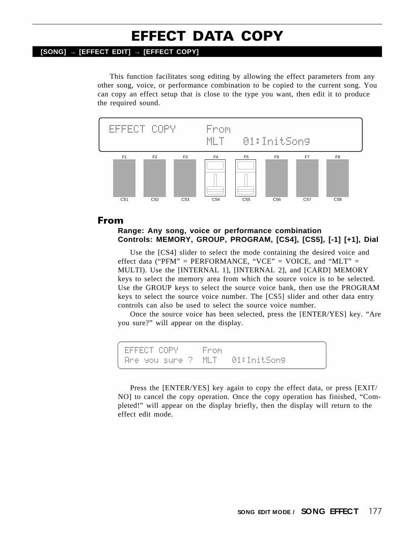
177SONG EDIT MODE / SONG EFFECT
This function facilitates song editing by allowing the effect parameters from anyother song, voice, or performance combination to be copied to the current song. Youcan copy an effect setup that is close to the type you want, then edit it to producethe required sound.
EFFECT DATA COPY[SONG] → [EFFECT EDIT] → [EFFECT COPY]
FromRange: Any song, voice or performance combinationControls: MEMORY, GROUP, PROGRAM, [CS4], [CS5], [-1] [+1], Dial
Use the [CS4] slider to select the mode containing the desired voice andeffect data (“PFM” = PERFORMANCE, “VCE” = VOICE, and “MLT” =MULTI). Use the [INTERNAL 1], [INTERNAL 2], and [CARD] MEMORYkeys to select the memory area from which the source voice is to be selected.Use the GROUP keys to select the source voice bank, then use the PROGRAMkeys to select the source voice number. The [CS5] slider and other data entrycontrols can also be used to select the source voice number.
Once the source voice has been selected, press the [ENTER/YES] key. “Areyou sure?” will appear on the display.
F1
CS1
F2
CS2
F3
CS3
F4
CS4
F5
CS5
F6
CS6
F7
CS7
F8
CS8
EFFECT`COPY`````From````````````````````
````````````````MLT```01:InitSong```````
EFFECT`COPY`````From````````````````````
Are`you`sure`?``MLT```01:InitSong```````
Press the [ENTER/YES] key again to copy the effect data, or press [EXIT/NO] to cancel the copy operation. Once the copy operation has finished, “Com-pleted!” will appear on the display briefly, then the display will return to theeffect edit mode.
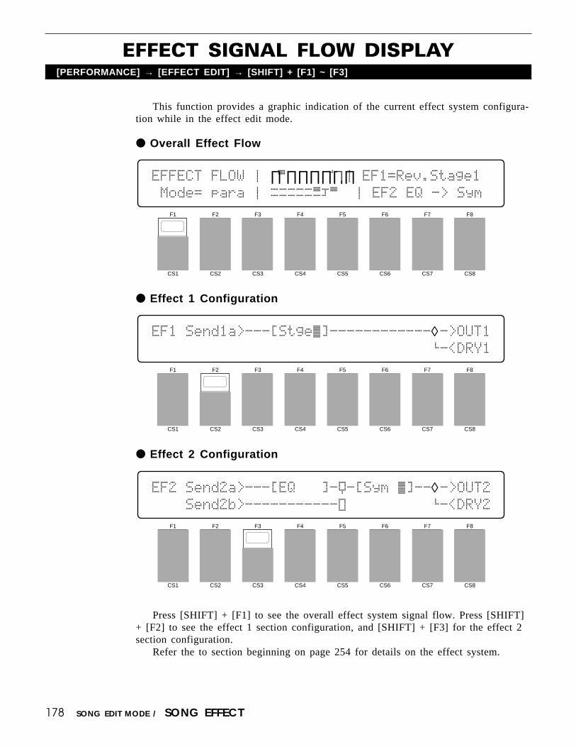
178 SONG EDIT MODE / SONG EFFECT
EFFECT SIGNAL FLOW DISPLAY[PERFORMANCE] → [EFFECT EDIT] → [SHIFT] + [F1] ~ [F3]
This function provides a graphic indication of the current effect system configura-tion while in the effect edit mode.
Overall Effect Flow
F1
CS1
F2
CS2
F3
CS3
F4
CS4
F5
CS5
F6
CS6
F7
CS7
F8
CS8
EFFECT`FLOW`Ú`∏Á∏∏∏∏∏∏Î`Ú`EF1=Rev.Stage1
`Mode=`para`Ú`ØØØØØËÔÁ `Ú`EF2`EQ`->`Sym
Effect 1 Configuration
F1
CS1
F2
CS2
F3
CS3
F4
CS4
F5
CS5
F6
CS6
F7
CS7
F8
CS8
EF1`Send1a>---[Stge˜]------------◊->OUT1`````````````````````````````````’-<DRY1
Effect 2 Configuration
F1
CS1
F2
CS2
F3
CS3
F4
CS4
F5
CS5
F6
CS6
F7
CS7
F8
CS8
EF2`Send2a>---[EQ```]-Ÿ-[Sym`˜]--◊->OUT2````Send2b>-----------Û``````````’-<DRY2
Press [SHIFT] + [F1] to see the overall effect system signal flow. Press [SHIFT]+ [F2] to see the effect 1 section configuration, and [SHIFT] + [F3] for the effect 2section configuration.
Refer the to section beginning on page 254 for details on the effect system.

179SONG EDIT MODE / SONG JOB
ONE, ALLRange: ONE, ALLControls: [F1], [F2]
Press [F1] if you want to clear the currently selected song, or [F2] if youwant to clear all songs in memory. If you select “ONE” song, the current songname is shown between parentheses on the lower display line.
Press [ENTER/YES] to begin the clear procedure. The following confirma-tion display will appear:
SONG`JOB`Clear`Song```````Are`you`sure`?
[ONE]`ALL````<InitSong>`````````````````
Press [ENTER/YES] again to confirm that you want to go ahead with theclear operation, or press [EXIT/NO] to cancel.
When the song data has been cleared, “Completed!” will appear briefly onthe display.
In addition to clearing all sequencer data for the current song, the clearfunction initializes the following parameters:
Song name: “InitSong”Tempo: 120Time signature: 4/4
Entirely clears all songs or just the currently selected song (one song) frommemory.
F1
CS1
F2
CS2
F3
CS3
F4
CS4
F5
CS5
F6
CS6
F7
CS7
F8
CS8
SONG`JOB`Clear`Song`````````````````````
[ONE]`ALL````<InitSong>`````````````````
[SONG] → [A]~[H] → [SONG JOB] → [MENU] → 1:Clear Song → [ENTER/YES]→ [1] → [SONG JOB] → [MENU] → 1:Clear Song → [ENTER/YES]
1: CLEAR SONG

180 SONG EDIT MODE / SONG JOB
Copies all song data from one song to any other. This can be handy if you wantto make minor changes to an existing song while retaining a copy of the originalsong data.
F1
CS1
F2
CS2
F3
CS3
F4
CS4
F5
CS5
F6
CS6
F7
CS7
F8
CS8
SONG`JOB`Copy`Song`````````````From`To``
`````````````<InitSong>````````S01``S01`
FromRange: 01 … 10Controls: [CS7], [-1] [+1], Dial
ToRange: 01 … 10Controls: [CS8], [-1] [+1], Dial
Use the [CS7] slider to select the “From” or source song number (1 … 10),and the [CS8] slider to select the “To” or desination song number. The name ofthe currently selected “From” or “To” song is shown between parentheses onthe lower display line, depending on which parameter the cursor is positionedbelow.
Press [ENTER/YES] to begin the copy procedure. The following confirma-tion display will appear:
SONG`JOB`Copy`Song````````Are`you`sure`?
`````````````<InitSong>````````S01``S01`
Press [ENTER/YES] again to confirm that you want to go ahead with thecopy operation (which will overwrite all data in the “To” song number), orpress [EXIT/NO] to cancel.
When the song data has been copied, “Completed!” will appear briefly onthe display.
[SONG] → [A]~[H] → [SONG JOB] → [MENU] → 2:Copy Song → [ENTER/YES]→ [1] → [SONG JOB] → [MENU] → 2:Copy Song → [ENTER/YES]
2: COPY SONG

181SONG EDIT MODE / SONG JOB
Indicates the amount of memory available for song recording.This job is not available when the rhythm track (track 9) is selected. The
“CLEAR RHYTHM TRACK” job described on page 182 appears in its place.
3: MEMORY STATUS[SONG] → [A]~[H] → [SONG JOB] → [MENU] → 3:Memory Status → [ENTER/YES]
A display of “Free=80%”, for example, means that approximately 20% ofthe available memory has been used, and approximately 80% is available forfurther recording.
A “Memory full” error message may appear during recording even if thisfunction does not indicate “Free=0%”. This is because a certain amount of free“work area’ is required by each function, and the memory can never be occu-pied entirely by song data.
F1
CS1
F2
CS2
F3
CS3
F4
CS4
F5
CS5
F6
CS6
F7
CS7
F8
CS8
SONG`JOB`Memory`Status`````````Free=100%
````````````````````````````````````````

182 SONG EDIT MODE / RHYTHM TRACK SONG JOB
Deletes all data from the rhythm track.This job appears in place of the “MEMORY STATUS” job, described on the
previous page, when the rhtyhm track (track 9) is selected.
3: CLEAR RHYTHM TRACK[SONG] → [1] → [SONG JOB] → [MENU] → 3:Clear Rhythm Track → [ENTER/YES]
F1
CS1
F2
CS2
F3
CS3
F4
CS4
F5
CS5
F6
CS6
F7
CS7
F8
CS8
SONG`JOB`Clear`Rhythm`Track
Press [ENTER/YES] to begin the delete procedure. The following confirma-tion display will appear:
SONG`JOB`Clear`Rhythm`Track
Are`you`sure`?
Press [ENTER/YES] again to confirm that you want to go ahead with thedelete operation, or press [EXIT/NO] to cancel.
When the rhythm track has been deleted, “Completed!” will appear brieflyon the display.

183SONG EDIT MODE / SONG JOB
Combines the data from two different tracks and copies the result to a third track.This job is not available when the rhythm track (track 9) is selected.
4: TRACK MIXDOWN[SONG] → [A]~[H] → [SONG JOB] → [MENU] → 4:Track Mixdown → [ENTER/YES]
From (From track 1 + track 2)Range: 1 … 8Controls: [CS6], [CS7], [-1] [+1], Dial
ToRange: 1 … 8Controls: [CS8], [-1] [+1], Dial
Use the [CS6] slider to select the first “From” (source) track and the [CS7]slider to select the second source track. The data from the first and secondsource tracks will be combined and copied to the “To” (destination) track,selected by the [CS8] slider.
Press [ENTER/YES] to begin the mixdown procedure. The following confir-mation display will appear:
F1
CS1
F2
CS2
F3
CS3
F4
CS4
F5
CS5
F6
CS6
F7
CS7
F8
CS8
SONG`JOB`Track`Mixdown````From``````To``
``````````````````````````TR1+`TR1¥`TR1`
SONG`JOB`Track`Mixdown````From``````To``
Are`you`sure`?````````````TR1+`TR1¥`TR1`
Press [ENTER/YES] again to confirm that you want to go ahead with themixdown operation (which will overwrite all data in the “To” track), or press[EXIT/NO] to cancel.
When the data has been mixed and copied, “Completed!” will appear brieflyon the display.
The mixdown function is most useful when you want to record more than 8individual parts. Successfully recorded parts can be combined using this func-tion, thus opening up more tracks for further recording. The data in the sourcetracks is not erased during a mixdown operation.
Please note that if both source tracks are set to the same track number, thedata from that track will simply be copied to the destination track.

184 SONG EDIT MODE / SONG JOB

185SONG EDIT MODE / SONG JOB
Deletes all data from the specified track.This job is not available when the rhythm track (track 9) is selected.
5: DELETE TRACK[SONG] → [A]~[H] → [SONG JOB] → [MENU] → 5:Delete Track → [ENTER/YES]
Use the GROUP [A] through [H] keys to select the track you want to delete(A = track1, B = track 2, and so on). The LED of the selected track will glowred while the LEDs of all other tracks containing data glow green. Press[ENTER/YES] to begin the delete procedure. The following confirmation dis-play will appear:
F1
CS1
F2
CS2
F3
CS3
F4
CS4
F5
CS5
F6
CS6
F7
CS7
F8
CS8
SONG`JOB`Delete`Track```````````````````
````````````````````````````````````````
SONG`JOB`Delete`Track```````````````````
``````````````````````````Are`you`sure`?
Press [ENTER/YES] again to confirm that you want to go ahead with thedelete operation, or press [EXIT/NO] to cancel.
When the track has been deleted, “Completed!” will appear briefly on thedisplay.

186 SONG EDIT MODE / SONG JOB
Aligns notes in the specified track to the nearest specified beat.This job is not available when the rhythm track (track 9) is selected.
6: QUANTIZE[SONG] → [A]~[H] → [SONG JOB] → [MENU] → 6:Quantize → [ENTER/YES]
F1
CS1
F2
CS2
F3
CS3
F4
CS4
F5
CS5
F6
CS6
F7
CS7
F8
CS8
SONG`JOB`Quantize`````````Meas`````Size`
``````````````````````````001ø`001`1/48`
Meas (First & last measure numbers)Range: 001 … 999Controls: [CS6], [CS7], [-1] [+1], Dial
SizeRange: 1/48, 1/32, 1/24, 1/16, 1/12, 1/8, 1/6, 1/4Controls: [CS8], [-1] [+1], Dial
Use the GROUP [A] through [H] keys to select the track you want toquantize (A = track1, B = track 2, and so on). The LED of the selected trackwill glow red while the LEDs of all other tracks containing data glow green.
Use the [CS6] and [CS7] sliders to select the numbers of the first and lastmeasures in the range of measures you want to quantize, and use the [CS8]slider to select the quantize size.
Press [ENTER/YES] to begin the quantize procedure. The following confir-mation display will appear:
SONG`JOB`Quantize`````````Meas`````Size`
Are`you`sure`?````````````001ø`001`1/48`
Press [ENTER/YES] again to confirm that you want to go ahead with thequantize operation, or press [EXIT/NO] to cancel.
When the data has been quantized, “Completed!” will appear briefly on thedisplay.

187SONG EDIT MODE / SONG JOB
Quantization is generally used to tighten up sloppy timing. Use it judi-ciously, however, because timing that is too perfect can sound cold and me-chanical — unless, of course, you’re specifically aiming for a cold, mechanicalfeel. Always use a quantize value that is at least as “short” as the shortestnotes in the track to be quantized. If you quantize a track containing 16th notesto 1/8 (8th notes), for example, some of the 16th notes will be aligned with 8thnote beats, thus ruining the track.
The various quantize values correspond to note lengths as follows:
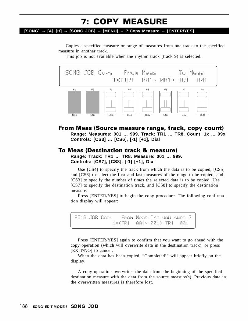
188 SONG EDIT MODE / SONG JOB
Copies a specified measure or range of measures from one track to the specifiedmeasure in another track.
This job is not available when the rhythm track (track 9) is selected.
7: COPY MEASURE[SONG] → [A]~[H] → [SONG JOB] → [MENU] → 7:Copy Measure → [ENTER/YES]
F1
CS1
F2
CS2
F3
CS3
F4
CS4
F5
CS5
F6
CS6
F7
CS7
F8
CS8
SONG`JOB`Copy```From`Meas``````To`Meas``
`````````````1Ê(TR1``001ø`001)`TR1``001`
From Meas (Source measure range, track, copy count)Range: Measures: 001 … 999. Track: TR1 … TR8. Count: 1x … 99xControls: [CS3] … [CS6], [-1] [+1], Dial
To Meas (Destination track & measure)Range: Track: TR1 … TR8. Measure: 001 … 999.Controls: [CS7], [CS8], [-1] [+1], Dial
Use [CS4] to specify the track from which the data is to be copied, [CS5]and [CS6] to select the first and last measures of the range to be copied, and[CS3] to specify the number of times the selected data is to be copied. Use[CS7] to specify the destination track, and [CS8] to specify the destinationmeasure.
Press [ENTER/YES] to begin the copy procedure. The following confirma-tion display will appear:
SONG`JOB`Copy```From`Meas`Are`you`sure`?
`````````````1Ê(TR1``001ø`001)`TR1``001`
Press [ENTER/YES] again to confirm that you want to go ahead with thecopy operation (which will overwrite data in the destination track), or press[EXIT/NO] to cancel.
When the data has been copied, “Completed!” will appear briefly on thedisplay.
A copy operation overwrites the data from the beginning of the specifieddestination measure with the data from the source measure(s). Previous data inthe overwritten measures is therefore lost.

189SONG EDIT MODE / SONG JOB

190 SONG EDIT MODE / SONG JOB
Deletes the specified measure or range of measures from all tracks.This job is not available when the rhythm track (track 9) is selected.
8: DELETE MEASURE[SONG] → [A]~[H] → [SONG JOB] → [MENU] → 8:Delete Measure → [ENTER/YES]
F1
CS1
F2
CS2
F3
CS3
F4
CS4
F5
CS5
F6
CS6
F7
CS7
F8
CS8
SONG`JOB`Delete`Measure````````Meas`````
`````````(`TR1ø8`All`)`````````001ø`001`
Meas (First & last measure numbers)Range: 001 … 999Controls: [CS7], [CS8], [-1] [+1], Dial
Use the [CS7] and [CS8] sliders to select the numbers of the first and lastmeasures in the range of measures you want to delete.
Press [ENTER/YES] to begin the delete procedure. The following confirma-tion display will appear:
SONG`JOB`Delete`Measure```Are`you`sure`?
`````````(`TR1ø8`All`)`````````001ø`001`
Press [ENTER/YES] again to confirm that you want to go ahead with thedelete operation, or press [EXIT/NO] to cancel.
When the data has been deleted, “Completed!” will appear briefly on thedisplay.
It’s important to remember that a delete operation affects all tracks simulta-neously, and that measures following the deleted range are moved back to takethe place of the deleted measures.

191SONG EDIT MODE / SONG JOB
Inserts a specified measure or range of measures from all tracks before any otherspecified measure.
This job is not available when the rhythm track (track 9) is selected.
9: INSERT MEASURE[SONG] → [A]~[H] → [SONG JOB] → [MENU] → 9:Insert Measure → [ENTER/YES]
From (Source measure range)Range: 001 … 999Controls: [CS6], [CS7], [-1] [+1], Dial
To (Destination measure)Range: 001 … 999Controls: [CS8], [-1] [+1], Dial
Use [CS6] and [CS7] to specify the first and last measures in the range tobe copied, and [CS8] to select the destination measure number at which thesource data will be inserted.
Press [ENTER/YES] to begin the insert procedure. The following confirma-tion display will appear:
F1
CS1
F2
CS2
F3
CS3
F4
CS4
F5
CS5
F6
CS6
F7
CS7
F8
CS8
SONG`JOB`Insert`Measure```From``````To``
`````````(`TR1ø8`All`)````001`ø001``001`
SONG`JOB`Insert`Measure```Are`you`sure`?
`````````(`TR1ø8`All`)````001`ø001``001`
Press [ENTER/YES] again to confirm that you want to go ahead with theinsert operation, or press [EXIT/NO] to cancel.
When the data has been inserted, “Completed!” will appear briefly on thedisplay.
Insert affects all tracks simultaneously. The source measure or range ofmeasures in inserted before the specified destination measure.
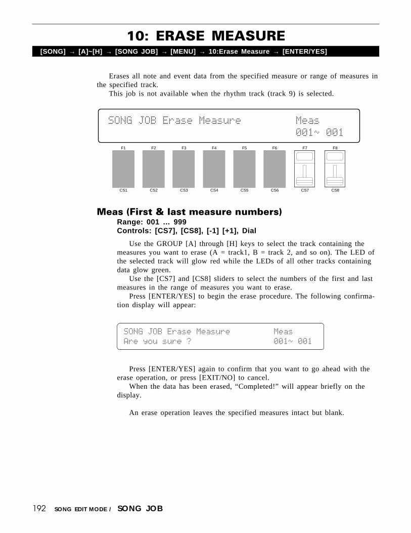
192 SONG EDIT MODE / SONG JOB
Erases all note and event data from the specified measure or range of measures inthe specified track.
This job is not available when the rhythm track (track 9) is selected.
10: ERASE MEASURE[SONG] → [A]~[H] → [SONG JOB] → [MENU] → 10:Erase Measure → [ENTER/YES]
F1
CS1
F2
CS2
F3
CS3
F4
CS4
F5
CS5
F6
CS6
F7
CS7
F8
CS8
SONG`JOB`Erase`Measure`````````Meas`````
```````````````````````````````001ø`001`
Meas (First & last measure numbers)Range: 001 … 999Controls: [CS7], [CS8], [-1] [+1], Dial
Use the GROUP [A] through [H] keys to select the track containing themeasures you want to erase (A = track1, B = track 2, and so on). The LED ofthe selected track will glow red while the LEDs of all other tracks containingdata glow green.
Use the [CS7] and [CS8] sliders to select the numbers of the first and lastmeasures in the range of measures you want to erase.
Press [ENTER/YES] to begin the erase procedure. The following confirma-tion display will appear:
SONG`JOB`Erase`Measure`````````Meas`````
Are`you`sure`?`````````````````001ø`001`
Press [ENTER/YES] again to confirm that you want to go ahead with theerase operation, or press [EXIT/NO] to cancel.
When the data has been erased, “Completed!” will appear briefly on thedisplay.
An erase operation leaves the specified measures intact but blank.

193SONG EDIT MODE / SONG JOB
Allows pitch bend, after touch, program change, or control change events (data) tobe removed from a specified measure or range of measures in a specified track.
This job is not available when the rhythm track (track 9) is selected.
11: REMOVE EVENT[SONG] → [A]~[H] → [SONG JOB] → [MENU] → 11:Remove Event → [ENTER/YES]
Event (Event type & No. if “ctrl” selected)Range: PB, AT, crtl, pgmControls: [CS5], [CS6], [-1] [+1], Dial
Meas (First & last measure numbers)Range: 001 … 999Controls: [CS7], [CS8], [-1] [+1], Dial
Use the GROUP [A] through [H] keys to select the track containing themeasures from which you want to remove events (A = track1, B = track 2, andso on). The LED of the selected track will glow red while the LEDs of allother tracks containing data glow green.
Use [CS5] to select the type of event to remove: “ctrl” for control change,“pgm” for program change, “AT” for aftertouch, and “PB” for pitch bend.Removing a program change (“pgm”) event also removes control changenumber 0 and 32 (bank select). If “ctrl” is selected, [CS6] can be used tospecify a control number to be removed (see below). Use the [CS7] and [CS8]sliders to select the numbers of the first and last measures in the range ofmeasures from which the specified event data is to be removed.
Press [ENTER/YES] to begin the remove event procedure. The followingconfirmation display will appear:
F1
CS1
F2
CS2
F3
CS3
F4
CS4
F5
CS5
F6
CS6
F7
CS7
F8
CS8
SONG`JOB`Remove`````Event``````Meas`````
``````````````````````PB```````001ø`001`
Press [ENTER/YES] again to confirm that you want to go ahead with theremove event operation, or press [EXIT/NO] to cancel.
When the data has been removed, “Completed!” will appear briefly on thedisplay.
SONG`JOB`Remove`````Event``````Meas`````
Are`you`sure`?````````PB```````001ø`001`

194 SONG EDIT MODE / SONG JOB
Control Change Numbers
If you choose to remove control change events — modulation wheel, breathcontroller, volume, etc. — you must also specify the control change number corre-sponding to the specific event you want to remove. For your reference, the followingis a list of assigned controllers:
MIDI CONTROL CHANGE NUMBER
0: “--------”1: “Mod.Whl.”2: “Breath C”4: “Foot Cnt”5: “Porta.Tm”6: “Data Ent”7: “Main Vol”8: “Balance ”10: “Panpot ”11: “Express.”64: “Hold 1 ”65: “Porta.Sw”66: “Sostenut”67: “Soft ”69: “Hold 2 ”
91: “Effect D”92: “TremoloD”93: “Chorus D”94: “CelesteD”95: “Phaser D”96: “Inc. ”97: “Dec. ”98: “NRPN LSB”99: “NRPN MSB”100: “RPN LSB”101: “RPN MSB”

195SONG EDIT MODE / SONG JOB
Moves all notes and events in the specified track and range of measures forwardor backward by the specified number of “clocks.”
This job is not available when the rhythm track (track 9) is selected.
12: CLOCK MOVE[SONG] → [A]~[H] → [SONG JOB] → [MENU] → 12:Clock Move → [ENTER/YES]
Meas (First & last measure numbers)Range: 001 … 999Controls: [CS6], [CS7], [-1] [+1], Dial
ClockRange: -999 … +999Controls: [CS8], [-1] [+1], Dial
Use the GROUP [A] through [H] keys to select the track on which theclock move operation is to be performed (A = track1, B = track 2, and so on).The LED of the selected track will glow red while the LEDs of all other trackscontaining data glow green.
Use [CS6] and [CS7] to specify the first and last measure numbers in therange of measures over which you want to shift the timing of note and eventdata. Use [CS8] to set the number of clocks by which the data will be movedforward or backward. Minus (-) values move the data backward (toward thebeginning of the song) while plus (+) values move the data forward (toward theend of the song). Each “clock” is equal to 1/48th of a quarter note.
Press [ENTER/YES] to begin the clock move procedure. The followingconfirmation display will appear:
F1
CS1
F2
CS2
F3
CS3
F4
CS4
F5
CS5
F6
CS6
F7
CS7
F8
CS8
SONG`JOB`Clock`Move```````Meas`````Clock
``````````````````````````001ø`001`+000`
SONG`JOB`Clock`Move```````Meas`````Clock
Are`you`sure`?````````````001ø`001`+000`
Press [ENTER/YES] again to confirm that you want to go ahead with theclock move operation, or press [EXIT/NO] to cancel.
When the data has been moved, “Completed!” will appear briefly on thedisplay.

196 SONG EDIT MODE / SONG JOB
Transposes all notes in the specified track and range of measures up or down bythe specified “offset” in semitones.
This job is not available when the rhythm track (track 9) is selected.
13: TRANSPOSE[SONG] → [A]~[H] → [SONG JOB] → [MENU] → 13:Transpose → [ENTER/YES]
F1
CS1
F2
CS2
F3
CS3
F4
CS4
F5
CS5
F6
CS6
F7
CS7
F8
CS8
SONG`JOB`Transpose````````Meas``````Ofst
``````````````````````````001ø`001```+0`
Meas (First & last measure numbers)Range: 001 … 999Controls: [CS6], [CS7], [-1] [+1], Dial
Ofst (Offset)Range: -99 … +99Controls: [CS8], [-1] [+1], Dial
Use the GROUP [A] through [H] keys to select the track on which thetranspose operation is to be performed (A = track1, B = track 2, and so on).The LED of the selected track will glow red while the LEDs of all other trackscontaining data glow green.
Use [CS6] and [CS7] to specify the first and last measure numbers in therange of measures over which you want to transpose note data. Use [CS8] toset the number of semitones by which the notes will be transposed up or down.Minus (-) values transpose down while plus (+) values transpose up.
Press [ENTER/YES] to begin the transpose procedure. The following confir-mation display will appear:
SONG`JOB`Transpose````````Meas``````Ofst
Are`you`sure`?````````````001ø`001```+0`
Press [ENTER/YES] again to confirm that you want to go ahead with thetranspose operation, or press [EXIT/NO] to cancel.
When the data has been transposed, “Completed!” will appear briefly on thedisplay.

197SONG EDIT MODE / SONG JOB
Shifts all occurences of the specified note in the specified track and range ofmeasures to any other note.
This job is not available when the rhythm track (track 9) is selected.
14: NOTE SHIFT[SONG] → [A]~[H] → [SONG JOB] → [MENU] → 14:Note Shift → [ENTER/YES]
F1
CS1
F2
CS2
F3
CS3
F4
CS4
F5
CS5
F6
CS6
F7
CS7
F8
CS8
SONG`JOB`Note`Shift``Meas``````From`To``
`````````````````````001ø`001```C≥```C≥
Meas (First & last measure numbers)Range: 001 … 999Controls: [CS5], [CS6], [-1] [+1], Dial
From (Original note)Range: C-2 … G8Controls: [CS7], [-1] [+1], Dial, Keyboard
To (New note)Range: C-2 … G8Controls: [CS8], [-1] [+1], Dial, Keyboard
Use the GROUP [A] through [H] keys to select the track on which the noteshift operation is to be performed (A = track1, B = track 2, and so on). TheLED of the selected track will glow red while the LEDs of all other trackscontaining data glow green.
Use [CS5] and [CS6] to specify the first and last measure numbers in therange of measures over which you want to shift note data. Use [CS7] to specifythe note that is to be shifted (or press the appropriate key on the keyboard aftermoving the cursor to the “From” parameter by pressing the [F7] key), and use[CS8] or the keyboard to specify the new note to which all occurrences of the“From” note are to be shifted.
Press [ENTER/YES] to begin the note shift procedure. The following con-firmation display will appear:
SONG`JOB`Note`Shift``Meas``````From`To``
Are`you`sure`?```````001ø`001```C≥```C≥
Press [ENTER/YES] again to confirm that you want to go ahead with thenote shift operation, or press [EXIT/NO] to cancel.
When the notes have been shifted, “Completed!” will appear briefly on thedisplay.
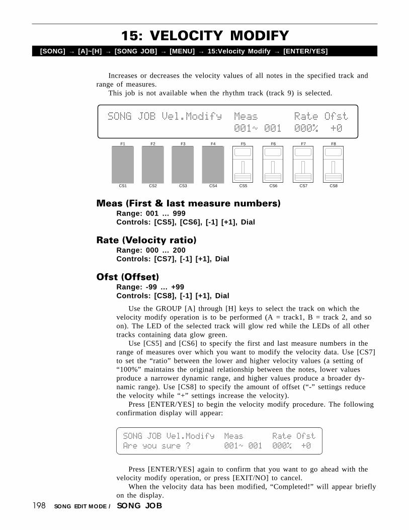
198 SONG EDIT MODE / SONG JOB
Increases or decreases the velocity values of all notes in the specified track andrange of measures.
This job is not available when the rhythm track (track 9) is selected.
15: VELOCITY MODIFY[SONG] → [A]~[H] → [SONG JOB] → [MENU] → 15:Velocity Modify → [ENTER/YES]
F1
CS1
F2
CS2
F3
CS3
F4
CS4
F5
CS5
F6
CS6
F7
CS7
F8
CS8
SONG`JOB`Vel.Modify``Meas``````Rate`Ofst
`````````````````````001ø`001``000%``+0`
Meas (First & last measure numbers)Range: 001 … 999Controls: [CS5], [CS6], [-1] [+1], Dial
Rate (Velocity ratio)Range: 000 … 200Controls: [CS7], [-1] [+1], Dial
Ofst (Offset)Range: -99 … +99Controls: [CS8], [-1] [+1], Dial
Use the GROUP [A] through [H] keys to select the track on which thevelocity modify operation is to be performed (A = track1, B = track 2, and soon). The LED of the selected track will glow red while the LEDs of all othertracks containing data glow green.
Use [CS5] and [CS6] to specify the first and last measure numbers in therange of measures over which you want to modify the velocity data. Use [CS7]to set the “ratio” between the lower and higher velocity values (a setting of“100%” maintains the original relationship between the notes, lower valuesproduce a narrower dynamic range, and higher values produce a broader dy-namic range). Use [CS8] to specify the amount of offset (“-” settings reducethe velocity while “+” settings increase the velocity).
Press [ENTER/YES] to begin the velocity modify procedure. The followingconfirmation display will appear:
SONG`JOB`Vel.Modify``Meas``````Rate`Ofst
Are`you`sure`?```````001ø`001``000%``+0`
Press [ENTER/YES] again to confirm that you want to go ahead with thevelocity modify operation, or press [EXIT/NO] to cancel.
When the velocity data has been modified, “Completed!” will appear brieflyon the display.

199SONG EDIT MODE / SONG JOB
Increases or decreases the gate times (length) of all notes in the specified trackand range of measures.
This job is not available when the rhythm track (track 9) is selected.
16: GATE TIME MODIFY[SONG] → [A]~[H] → [SONG JOB] → [MENU] → 16:Gate Time Modify → [ENTER/YES]
F1
CS1
F2
CS2
F3
CS3
F4
CS4
F5
CS5
F6
CS6
F7
CS7
F8
CS8
SONG`JOB`Gate`Modify`Meas``````Rate`Ofst
`````````````````````001ø`001``000%``+0`
Press [ENTER/YES] again to confirm that you want to go ahead with thegate time modify operation, or press [EXIT/NO] to cancel.
When the gate time data has been modified, “Completed!” will appearbriefly on the display.
Meas (First & last measure numbers)Range: 001 … 999Controls: [CS5], [CS6], [-1] [+1], Dial
Rate (Gate time ratio)Range: 000 … 200Controls: [CS7], [-1] [+1], Dial
Ofst (Offset)Range: -99 … +99Controls: [CS8], [-1] [+1], Dial
Use the GROUP [A] through [H] keys to select the track on which the gatetime modify operation is to be performed (A = track1, B = track 2, and so on).The LED of the selected track will glow red while the LEDs of all other trackscontaining data glow green.
Use [CS5] and [CS6] to specify the first and last measure numbers in therange of measures over which you want to modify the gate time data. Use[CS7] to set the “ratio” between the shorter and longer gate time values (asetting of “100%” maintains the original relationship between the notes, lowervalues produce a narrower gate time range, and higher values produce a broadergate time range). Use [CS8] to specify the amount of offset (“-” settingsshorten the gate time while “+” settings increase the gate time).
Press [ENTER/YES] to begin the gate time modify procedure. The follow-ing confirmation display will appear:
SONG`JOB`Gate`Modify`Meas``````Rate`Ofst
Are`you`sure`?```````001ø`001``000%``+0`

200 SONG EDIT MODE / SONG JOB
Produces a crescendo or decrescendo across the specified range of measures in theselected track by gradually increasing or decreasing the note velocity values.
This job is not available when the rhythm track (track 9) is selected.
17: CRESCENDO[SONG] → [A]~[H] → [SONG JOB] → [MENU] → 17:Crescendo → [ENTER/YES]
F1
CS1
F2
CS2
F3
CS3
F4
CS4
F5
CS5
F6
CS6
F7
CS7
F8
CS8
SONG`JOB`Crescendo````````Meas``````Rng`
``````````````````````````001ø`001```+0`
Meas (First & last measure numbers)Range: 001 … 999Controls: [CS6], [CS7], [-1] [+1], Dial
Rng (Range)Range: -99 … +99Controls: [CS8], [-1] [+1], Dial
Use the GROUP [A] through [H] keys to select the track on which thecrescendo operation is to be performed (A = track1, B = track 2, and so on).The LED of the selected track will glow red while the LEDs of all other trackscontaining data glow green.
Use [CS6] and [CS7] to specify the first and last measure numbers in therange of measures over which you want to produce a crescendo or decrescendo.Use [CS8] to specify the final range of the crescendo or decrescendo: “-”settings produce a decrescendo while “+” settings produce a crescendo.
Press [ENTER/YES] to begin the crescendo procedure. The following con-firmation display will appear:
SONG`JOB`Crescendo````````Meas``````Rng`
Are`you`sure`?````````````001ø`001```+0`
Press [ENTER/YES] again to confirm that you want to go ahead with thecrescendo operation, or press [EXIT/NO] to cancel.
When the crescendo or decrescendo has been created, “Completed!” willappear briefly on the display.

PATTERN EDIT MODE

202 PATTERN EDIT MODE / PATTERN JOB
Copies all pattern data from one pattern to any other. This can be handy if youwant to make minor changes to an existing pattern while retaining a copy of theoriginal pattern data. It is also possible to append one pattern to another, and copythe result to a new pattern number.
1: COPY PATTERN[PATTERN] → [JOB] → [MENU] → 1:Copy Pattern → [ENTER/YES]
F1
CS1
F2
CS2
F3
CS3
F4
CS4
F5
CS5
F6
CS6
F7
CS7
F8
CS8
PTN`JOB`Copy`Pattern``````From``````To``
```````````````<Funk1``V>`I00+`***``I00`
From (Source and append patterns)Range: 00 … 99Controls: [CS6], [CS7], [-1] [+1], Dial
ToRange: 00 … 99Controls: [CS8], [-1] [+1], Dial
Use [CS6] to select the “From” or source pattern number (0 … 99), [CS7]to select a pattern to be appended to the end of the of the first pattern (leavethis parameter set to “***” if you do not want to append a pattern), and [CS8]to select the “To” or destination pattern number. The name of the currentlyselected “From” or “To” pattern is shown between parentheses on the lowerdisplay line, depending on which parameter the cursor is positioned below.
Press [ENTER/YES] to begin the copy procedure. The following confirma-tion display will appear:
PTN`JOB`Copy`Pattern``````From``````To``
Are`you`sure`?`<Funk1``V>`I00+`***``I00`
Press [ENTER/YES] again to confirm that you want to go ahead with thecopy operation (which will overwrite all data in the “To” pattern number), orpress [EXIT/NO] to cancel.
When the pattern data has been copied, “Completed!” will appear briefly onthe display.

203PATTERN EDIT MODE / PATTERN JOB
Entirely clears all patterns, a single pattern, or one instrument (key) from a se-lected pattern.
2: CLEAR PATTERN[PATTERN] → [JOB] → [MENU] → 2:Clear Pattern → [ENTER/YES]
PTN, ALL, KEYRange: PTN, ALL, KEYControls: [F1], [F2], [F3]
Ptn (Pattern number)Range: 00 … 99Controls: [CS6], [-1] [+1], Dial
KeyRange: 36 … 96 (C1 … C6)Controls: [CS7], [-1] [+1], Dial, Keyboard
Press [F1] if you want to clear one pattern, [F2] if you want to clear allpatterns in memory, or [F3] if you want to clear a specified instrument (key)from a selected pattern. If you select “PTN”, the current pattern name is shownbetween parentheses on the lower display line and [CS6] can be used to selectthe pattern to be cleared.
If you select “KEY”, the current pattern name is shown between parenthe-ses on the lower display line, [CS6] can be used to select the pattern fromwhich an instrument is to be cleared, and [CS7] is used to select the key to becleared. The key to be cleared can also be directly specified by pressing theappropriate key on the keyboard. The MIDI note number corresponding to theselected instrument/key is shown on the lower display line while the note name(C1 … C6) is shown on the upper line.
Press [ENTER/YES] to begin the clear procedure. The following confirma-tion display will appear:
PTN`JOB`Clear`Pattern`````Are`you`sure`?
[PTN]`ALL``KEY`<Funk1``V>`I00w``````````
Press [ENTER/YES] again to confirm that you want to go ahead with theclear operation, or press [EXIT/NO] to cancel.
When the specified data has been cleared, “Completed!” will appear brieflyon the display.
F1
CS1
F2
CS2
F3
CS3
F4
CS4
F5
CS5
F6
CS6
F7
CS7
F8
CS8
PTN`JOB`Clear`Pattern`````Ptn```````````
[PTN]`ALL``KEY`<Funk1``V>`I00w``````````

204
Allows a specified instrument (key) in one or all patterns to be changed to anyother. This makes it possible to change all occurences of one instrument to a differentinstrument in one easy step.
3: INSTRUMENT CHANGE[PATTERN] → [JOB] → [MENU] → 3:Inst Change → [ENTER/YES]
PATTERN EDIT MODE / PATTERN JOB
PTN, ALLRange: PTN, ALLControls: [F1], [F2]
Ptn (Pattern number)Range: 00 … 99Controls: [CS6], [-1] [+1], Dial
FromRange: C1 … C6Controls: [CS7], [-1] [+1], Dial, Keyboard
ToRange: C1 … C6Controls: [CS8], [-1] [+1], Dial, Keyboard
Press [F1] if you want to change an instrument in one pattern, or [F2] ifyou want to change an instrument in all patterns. If you select “PTN”, thecurrent pattern name is shown between parentheses on the lower display lineand [CS6] can be used to select the pattern in which an instrument is to bechanged. Use [CS7] (“From”) to select the key corresponding to the instrumentto be changed, and [CS8] (“To”) to select the key corresponding to the newinstrument. The “From” and “To” keys can also be directly specified via thekeyboard when the cursor is located at the corresponding parameter.
Press [ENTER/YES] to begin the instrument change procedure. The follow-ing confirmation display will appear:
PTN`JOB`Inst`Change```````Are`you`sure`?
[PTN]`ALL``````<Funk1``V>`I00```C1```C1`
Press [ENTER/YES] again to confirm that you want to go ahead with theinstrument change operation, or press [EXIT/NO] to cancel.
When the instrument has been changed, “Completed!” will appear briefly onthe display, then the display will return to the pattern play mode.
F1
CS1
F2
CS2
F3
CS3
F4
CS4
F5
CS5
F6
CS6
F7
CS7
F8
CS8
PTN`JOB`Inst`Change```````Ptn``From``To`
[PTN]`ALL``````<Funk1``V>`I00```C1```C1`

205
4: VELOCITY MODIFY[PATTERN] → [JOB] → [MENU] → 4:Velocity Modify → [ENTER/YES]
PATTERN EDIT MODE / PATTERN JOB
Inceases or decreases the velocity values of all occurences of the specified instru-ment (key) in the specified pattern or all patterns.
PTN, ALLRange: PTN, ALLControls: [F1], [F2]
Ptn (Pattern number)Range: 00 … 99Controls: [CS5], [-1] [+1], Dial
KeyRange: C1 … C6Controls: [CS6], [-1] [+1], Dial, Keyboard
Rate (Velocity ratio)Range: 000 … 200Controls: [CS7], [-1] [+1], Dial
F1
CS1
F2
CS2
F3
CS3
F4
CS4
F5
CS5
F6
CS6
F7
CS7
F8
CS8
PTN`JOB`Velocity`````Ptn``Key``Rate`Ofst
[PTN]`ALL`<Funk1``V>`I00```C1``000%``+0`

206
Ofst (Offset)Range: -99 … +99Controls: [CS8], [-1] [+1], Dial
Press [F1] if you want to modify the velocity values of an instrument inone pattern, or [F2] if you want to modify the velocity values of an instrumentin all patterns. If you select “PTN”, the current pattern name is shown betweenparentheses on the lower display line and [CS5] can be used to select thepattern in which the velocity values are to be modified. Use [CS6] to select theinstrument (key) for which the velocity values are to be modified. Use [CS7] toset the “ratio” between the lower and higher velocity values (a setting of“100%” maintains the original relationship between the notes, lower valuesproduce a narrower dynamic range, and higher values produce a broader dy-namic range). Use [CS8] to specify the amount of offset (“-” settings reducethe velocity while “+” settings increase the velocity).
Press [ENTER/YES] to begin the velocity modify procedure. The followingconfirmation display will appear:
PATTERN EDIT MODE / PATTERN JOB
PTN`JOB`Velocity`````ptn``Are`you`sure`?
[PTN]`ALL`<Funk1``V>`I00```C1``000%``+0`
Press [ENTER/YES] again to confirm that you want to go ahead with thevelocity modify operation, or press [EXIT/NO] to cancel.
When the velocity data has been modified, “Completed!” will appear brieflyon the display, then the display will return to the pattern play mode.

207
This function can be used to assign a name of up to 8 characters to the currentpattern.
PATTERN NAME[PATTERN] → [NAME]
PATTERN EDIT MODE / PATTERN NAME
F1
CS1
F2
CS2
F3
CS3
F4
CS4
F5
CS5
F6
CS6
F7
CS7
F8
CS8
Pattern`Name`````````````I00`:"Funk1``V"
[CLR][UPR][LWR][SPC]````````````[†]``[¥]
NameRange: See character list, belowControls: GROUP, PROGRAM, [CS1] … [CS8], [-1] [+1], Dial
Assigns a name of up to 8 characters to the current pattern.Use the [F7] function key to move the character cursor to the left, and the
[F8] function key to move the cursor to the right. Use the GROUP and PRO-GRAM keys to input a character at the cursor position. Each GROUP or PRO-GRAM key selects the three characters printed above it in sequence. It is alsopossible to use the [-1] and [+1] keys or dial to scroll through the availablecharacters (see list below).
The sliders, [CS1] through [CS8], independently select characters for thecorresponding character position: [CS1] selects the first character, [CS2] selectsthe second character, and so on.
The first four function keys also perform important functions: [F1] clearsthe entire name, [F2] selects upper-case characters for GROUP and PROGRAMkey entry, [F3] selects lower-case characters for GROUP and PROGRAM keyentry, and [F4] inserts a space at the cursor position.
[A]: A → B → C[B]: D → E → F[C]: G → H → I[D]: J → K → L[E]: M → N → O[F]: P → Q → R[G]: S → T → U[H]: V → W → X
[1]: Y → Z → 0[2]: 1 → 2 → 3[3]: 4 → 5 → 6[4]: 7 → 8 → 9[5]: * → & → _[6]: / → . → ,[7]: ’ → ! → ?[8]: # → : → ;
PROGRAM keyGROUP key


UTILITY MODE

210 UTILITY MODE / SYNTH SETUP
This screen includes several parameters that affect overall operation of the SY85.
1: SYSTEM[UTILITY] → [SYNTH SETUP] → [MENU] → 1:System → [ENTER/YES]
F1
CS1
F2
CS2
F3
CS3
F4
CS4
F5
CS5
F6
CS6
F7
CS7
F8
CS8
SYNTH`SYSTEM```NtShft`Tune`CtrlRst`Local
`````````````````+0````+0``````off```on
NtShft (Note shift)Range: -63 … +63Controls: [CS4], [-1] [+1], Dial,
Shifts the overall pitch of the SY85 up or down in semitone steps.A setting of “-12,” for example, shifts the pitch down by one octave; a
setting of “+4” shifts the pitch up by a major third.
Tune (Master tuning)Range: -63 … +63Controls: [CS5], [-1] [+1], Dial,
Fine tunes the overall pitch of the SY85 in approximately 1.17-cent steps (a“cent” is 1/100th of a semitone).
The maximum minus setting of “-63” produces a downward pitch shift ofalmost three-quarters of a semitone, and the maximum plus setting of “+63”produces an upward pitch shift of the same amount. A setting of “0” producesno pitch change.
CtrlRst (Control reset)Range: off, onControls: [CS7], [-1] [+1], Dial
Determines whether controller settings (modulation wheel, pitch bend,breath controller, foot controller, etc.) are held (“off”) or reset (“on”) whenvoices or multi-play setups are switched.
If this function is set to “off,” then if, for example, you have applied modu-lation to a voice via the modulation wheel and switch to a new voice whilemaintaining the same modulation wheel position, then the same amount ofmodulation will be applied to the new voice. If “on” is selected, than all con-troller values are reset when a new voice or multi-play setup is selected.
211UTILITY MODE / SYNTH SETUP
LocalRange: off, onControls: [CS8], [-1] [+1], Dial,
“Local control” refers to the fact that, normally, the SY85 keyboard con-trols its internal tone generator, allowing the internal voices to be played di-rectly from the keyboard. This situation is “Local Control ON” since the inter-nal tone generator is controlled locally by its own keyboard. Local control canbe turned OFF, however, so that the keyboard does not play the internal voices,but the appropriate MIDI information is still transmitted via the MIDI OUTconnector when notes are played on the keyboard. At the same time, the inter-nal tone generator responds to MIDI information received via the MIDI INconnector.

212 UTILITY MODE / SYNTH SETUP
The MIDI channel parameters provided here are essential to ensure proper com-munication between the SY85 and other MIDI instruments.
2: MIDI 1 (CHANNEL PARAMETERS)[UTILITY] → [SYNTH SETUP] → [MENU] → 2:MIDI 1 → [ENTER/YES]
F1
CS1
F2
CS2
F3
CS3
F4
CS4
F5
CS5
F6
CS6
F7
CS7
F8
CS8
SYNTH`MIDI`1`````````Tch``Rch`DevNo`````
``````````````````````01`omni``all
Tch (Transmit channel)Range: 1 … 16Controls: [CS5], [-1] [+1], Dial
Selects the MIDI channel via which all SY85 data will be transmitted.
Rch (Receive channel)Range: 1 … 16, omniControls: [CS6], [-1] [+1], Dial
Sets the MIDI receive channel to any channel between 1 and 16, or the“omni” mode for reception on all channels. Make sure that the SY85 MIDIreceive channel is either set to the channel that your external controller istransmitting on, or the omni mode.
DevNo (Device number)Range: off, 1 … 16, allControls: [CS7], [-1] [+1], Dial
Sets the SY85 MIDI device number — i.e. the MIDI channel on which allsystem exclusive data will be received and transmitted.
The device number is important for transfer of voice data and other systemexclusive data between the SY85 and other Yamaha MIDI devices — e.g.another SY85 or SY-series synthesizer, a Yamaha MIDI sequence recorder suchas the QX3, etc. Bulk voice data, for example, is transmitted and received onthe channel specified by the device number. Make sure that the SY85 devicenumber is matched to that of other devices in your system with which suchdata transfers will take place.

213UTILITY MODE / SYNTH SETUP
More MIDI parameters that determine how the SY85 responds to external MIDIcontrol.
3: MIDI 2 (OTHER PARAMETERS)[UTILITY] → [SYNTH SETUP] → [MENU] → 3:MIDI 2 → [ENTER/YES]
VolCtrl (Volume control device)Range: 000 … 121Controls: [CS4], [-1] [+1], Dial
Sets a MIDI control number via which the overall volume of the SY85 canbe controlled.
PC (Program change type)Range: off, norm, drct, tblControls: [CS5], [-1] [+1], Dial
Determines whether the SY85 will respond to MIDI program change mes-sages for remote voice/performance selection.
The “off” setting turns MIDI program change reception off, so operating thevoice selectors on an external controller will not cause the corresponding SY85voice or performance setup to be selected.
In the “norm” (normal) mode, program change numbers 0 through 63 selectSY85 voices or performance combinations 1 through 64, depending on thecurrent mode.
The “drct” (direct) mode allows, in addition to the voice and performanceselection of the “norm” mode, selection of the various SY85 modes by recep-tion of the MIDI program bank change messages listed below.
F1
CS1
F2
CS2
F3
CS3
F4
CS4
F5
CS5
F6
CS6
F7
CS7
F8
CS8
SYNTH`MIDI`2`VolCtrl`PC``Bulkprot```````
``````(Main`Vol)007`drct```on

214 UTILITY MODE / SYNTH SETUP
When “tbl” (table) is selected, transmission conforms to the program changetable (see “4: PROGRAM CHANGE TABLE,” below), while reception is thesame as in the “drct” mode, above.
Bulkprot (Bulk receive protect)Range: off, onControls: [CS6], [-1] [+1], Dial
Enables or disables bulk data reception. When this function is set to “off,”the SY85 will automatically receive a bulk dump of voice, multi-play or systemdata from an external device connected to its MIDI IN terminal when theappropriate bulk dump data is received (assuming that the SY85 and transmit-ting device are both set to the same device number).
Turn bulk in protect “on” to disable bulk dump reception (this preventsaccidental disruption of the SY85 during use).
MIDI PROGRAM BANKCHANGE MESSAGE
Voice
Performance
Voice(multi)
Performance(multi)
“00H” “20H”MEMORYMODE
000306090104070A
40434144
202326292124272A
50535154
0000000000000000
00000000
0000000000000000
00000000
Internal1Internal2Internal3Internal4
Card1Card2Card3Card4
Internal1Internal2
Card1Card2
Internal1Internal2Internal3Internal4
Card1Card2Card3Card4
Internal1Internal2
Card1Card2

215UTILITY MODE / SYNTH SETUP
These parameters make it possible to specify what MIDI program change numberis transmitted via the MIDI OUT connector when any of the internal voice or per-formance memory locations are selected.
4: PROGRAM CHANGE TABLE[UTILITY] → [SYNTH SETUP] → [MENU] → 4:Program Change Table → [ENTER/YES]
SourceRange: A1 … H8Controls: [CS5], GROUP, PROGRAM, [-1] [+1], Dial
Specifies the source voice number (GROUP and PROGRAM) which, whenselected on the SY85, will cause the bank and program change numbers speci-fied by the “MSB”, “LSB”, and “PGM” parameters, described below, to betransmitted via the MIDI OUT connector.
MSB (Bank select most significant bits)Range: 000 … 127Controls: [CS6], [-1] [+1], Dial
Sets the decimal value of the most significant bits of the bank select codeto be transmitted when the source voice number is selected. The specific func-tions of the bank select codes are determined by individual instrument manufac-turers, so, if you intend to use these codes, refer to the documentation of thedevice you intend to control.
LSB (Bank select least significant bits)Range: 000 … 127Controls: [CS7], [-1] [+1], Dial
Sets the decimal value of the least significant bits of the bank select codeto be transmitted when the source voice number is selected. See “MSB”, above,for more details.
PGM (Program change number)Range: 00 … 127Controls: [CS8], [-1] [+1], Dial
Sets the MIDI program change number to be transmitted via the MIDI OUTconnector when the corresponding “Source” voice number is selected.
F1
CS1
F2
CS2
F3
CS3
F4
CS4
F5
CS5
F6
CS6
F7
CS7
F8
CS8
SYNTH`PC`TABLE````BankSel(MSB)(LSB)`PGM`
(Transmit`Only)Source=A1``000``064``000`

216 UTILITY MODE / SYNTH SETUP
Thge SY85 offers a range of keyboard velocity curves that produce subtly differ-ent responses to keyboard dynamics. Choose the velocity curve that best suits yourpersonal style of expression.
5: VELOCITY[UTILITY] → [SYNTH SETUP] → [MENU] → 5:Velocity → [ENTER/YES]
F1
CS1
F2
CS2
F3
CS3
F4
CS4
F5
CS5
F6
CS6
F7
CS7
F8
CS8
SYNTH`OTHER`Vel)Crv``Fix````````````````
``````````(normal)0``off````````````````
Crv (Velocity curve)Range: 0 … 7Controls: [CS4], [-1] [+1], Dial
Selects one of eight different velocity curves.
0: normal1: soft12: soft23: easy4: wide5: hard6: cross17: cross2
The velocity curves determine how the SY85 responds to different velocityvalues (i.e. keyboard dynamics). Different keyboards and controllers havedifferent velocity sensitivity, and different players have individual preferences.This function lets you select the velocity curve that best suits your keyboard/controller and playing style. Try each one out to find the one you like best.
FixRange: off, 1 … 127Controls: [CS5], [-1] [+1], Dial
Sets an absolute velocity value. All notes played, no matter how hard theyare played, are sounded at the specified velocity value. When this parameter isset to “off” normal keyboard velocity control is enabled.

217UTILITY MODE / SEQUENCER SETUP
The parametrers provided in this screen determine how the sequencer’s metronomefunctions, and whether sequencer operation is synchronized to the SY85’s own inter-nal clock or an external MIDI device.
1: CLICK CONDITION[UTILITY] → [SEQ SETUP] → [MENU] → 1:Click Condition → [ENTER/YES]
ClickRange: off, onControls: [CS3], [-1] [+1], Dial
Enables or disables the sequencer’s metronome click sound.The “off” setting means that the metronome never sounds. This setting is
useful for recording free-tempo passages. The “on” setting causes the metro-nome to sound during real-time recording.
The volume of the click metronome sound can be adjusted via the rear-panel [CLICK VOLUME] control.
BeatRange: 1/4, 1/6, 1/8, 1/12, 1/16, 1/24, 1/32Controls: [CS4], [-1] [+1], Dial
Effective only in the pattern mode, this parameter determines how manymetronome beats occur between each accented beat.
ClockRange: int, MIDIControls: [CS5], [-1] [+1], Dial
Determines whether the SY85 sequencer timing is synchronized by its owninternal clock or an external MIDI clock.
“int” (internal) is the normal setting when the SY85 is being used alone. Ifyou are using the SY85 with an external sequencer, MIDI computer, or otherMIDI device, and you want the SY85 to be synchronized to the external device,set this function to MIDI. In the latter case, the external device must be con-nected to the SY85 MIDI IN connector, and must be transmitting an appropri-ate MIDI clock signal.
F1
CS1
F2
CS2
F3
CS3
F4
CS4
F5
CS5
F6
CS6
F7
CS7
F8
CS8
SEQUENCER`Click`Beat`Clock`````MIDI`Ctrl
````````````on```1/4``int````````````on`
218 UTILITY MODE / SEQUENCER SETUP
MIDI CtrlRange: off, onControls: [CS8], [-1] [+1], Dial
Enables or disables reception and transmission of MIDI start, stop, andcontinue messages; enables or disables MIDI clock transmission; and enables ordisables MIDI song position pointer reception.

219UTILITY MODE / SEQUENCER SETUP
Since you might want to use the SY85 sequencer to record material from anexternal MIDI device rather than the instrument’s own keyboard, the Receive Channelparameter on this page is provided so you can specify reception on any MIDI chan-nel. The Aftertouch parameter is used to turn recording of aftertouch data on or off.
2: RECORD CONDITION[UTILITY] → [SEQ SETUP] → [MENU] → 2:Rec Condition → [ENTER/YES]
Rch (Receive channel)Range: 1 … 16, omni, kbdControls: [CS7], [-1] [+1], Dial
Selects input from the SY85 keyboard, or sets the MIDI receive channelwhen data is to be recorded from an external MIDI device.
This function must be set to “kbd” if you will be recording from the SY85keyboard. If you will be recording from an external MIDI controller such as amaster keyboard or wind controller, however, select the appropriate MIDIchannel or the “omni” mode for reception on all MIDI channels.
AT (Aftertouch)Range: off, onControls: [CS8], [-1] [+1], Dial
Turns recording of after touch data on or off.After touch data tends to be quite voluminous, and can use up the
sequencer memory capacity quickly, For this reason, the default setting for aftertouch data recording is “off.” turn this parameter “on” only if you specificallywant to use an after touch effect.
F1
CS1
F2
CS2
F3
CS3
F4
CS4
F5
CS5
F6
CS6
F7
CS7
F8
CS8
SEQUENCER`Rec`Condition````````Rch```AT`
```````````````````````````````kbd``off`

220 UTILITY MODE / SEQUENCER SETUP
Determine the velocity values of three accent types that can be entered in thesong/pattern step record mode and in the pattern real-time record mode, and of thefixed velocity value for all record modes.
3: ACCENT VELOCITY[UTILITY] → [SEQ SETUP] → [MENU] → 3:Accent Velocity → [ENTER/YES]
F1
CS1
F2
CS2
F3
CS3
F4
CS4
F5
CS5
F6
CS6
F7
CS7
F8
CS8
SEQUENCER`Accent`````ACC1`ACC2`ACC3`FIX`
``````````````````````56```88``120``kbd`
ACC1, ACC2, ACC3 (Accents 1 … 3)Range: 1 … 127Controls: [CS5], [CS6], [CS7], [-1] [+1], Dial
[CS5], [CS6], and [CS7] set the ACC1, ACC2, and ACC3 velocity values,respectively. Refer to the step recording instructions beginning on page 52 ofthe “Getting Started” manual for more information about the accents.
FIXRange: 1 … 127, kbdControls: [CS8], [-1] [+1], Dial
Set to “kbd” for normal velocity control during recording, or to a specificfixed velocity value, as required. The specified value will be used for all songand pattern recording.
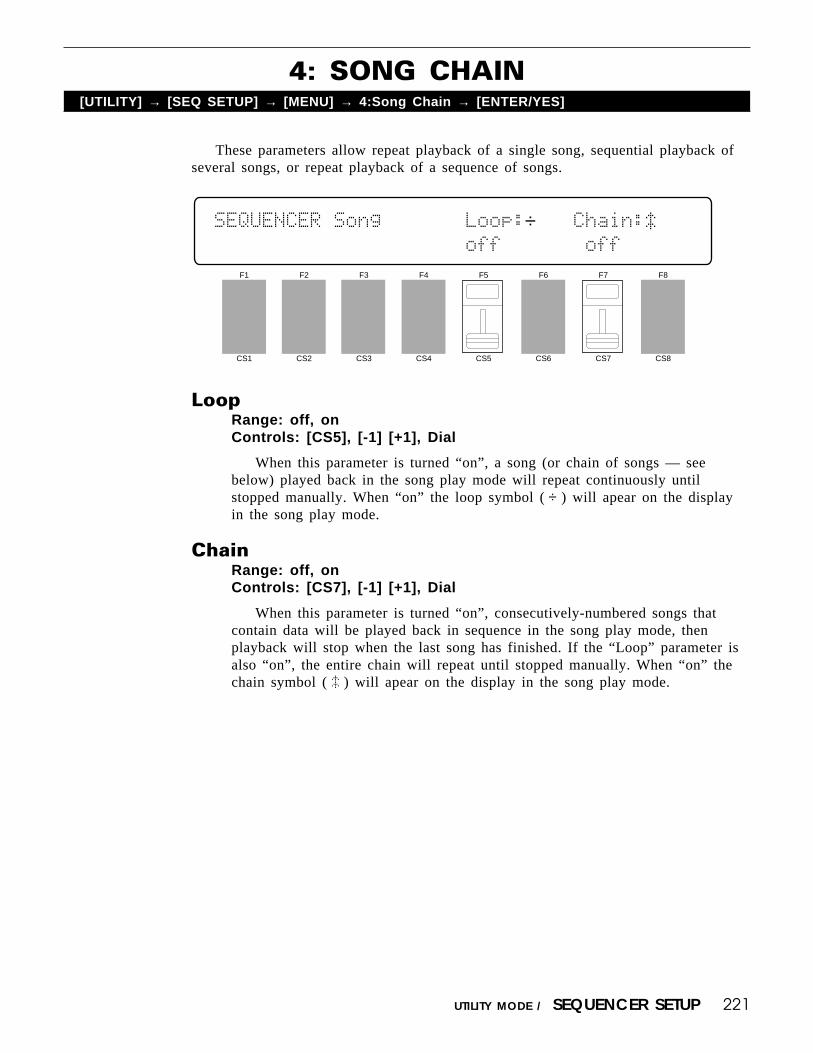
221UTILITY MODE / SEQUENCER SETUP
These parameters allow repeat playback of a single song, sequential playback ofseveral songs, or repeat playback of a sequence of songs.
4: SONG CHAIN[UTILITY] → [SEQ SETUP] → [MENU] → 4:Song Chain → [ENTER/YES]
LoopRange: off, onControls: [CS5], [-1] [+1], Dial
When this parameter is turned “on”, a song (or chain of songs — seebelow) played back in the song play mode will repeat continuously untilstopped manually. When “on” the loop symbol ( ÷ ) will apear on the displayin the song play mode.
ChainRange: off, onControls: [CS7], [-1] [+1], Dial
When this parameter is turned “on”, consecutively-numbered songs thatcontain data will be played back in sequence in the song play mode, thenplayback will stop when the last song has finished. If the “Loop” parameter isalso “on”, the entire chain will repeat until stopped manually. When “on” thechain symbol ( º ) will apear on the display in the song play mode.
F1
CS1
F2
CS2
F3
CS3
F4
CS4
F5
CS5
F6
CS6
F7
CS7
F8
CS8
SEQUENCER`Song```````Loop:÷```Chain:º````````````````````````off```````off``````

222 UTILITY MODE / MIDI
Initiates MIDI bulk transmission of the selected voice, multi-play, and/or systemdata.
BULK DUMP[UTILITY] → [MIDI]
F1
CS1
F2
CS2
F3
CS3
F4
CS4
F5
CS5
F6
CS6
F7
CS7
F8
CS8
Bulk`Dump````Type```````````````````````
`````````````1`:all
TypeRange: all, synth all, sequencer all, pattern all, 1 performance, 1
voice, 1 songControls: [CS3], [-1] [+1], Dial
Use [CS3] to select the type of data you want to transmit. The various datatypes are as follows:
1: all All internal data.2: synth all All synthesizer data, including setup, performance
combinations, and voices.3: sequencer all All sequencer data, including setup, songs,and patterns.4: pattern all All patterns.5: 1 performance The currently selected performance combination.6: 1 voice The currently selected voice.7: 1 song The currently selected song, including multi data.
Press [ENTER/YES] to begin the bulk dump procedure. The followingconfirmation display will appear:
Bulk`Dump````Type`````````Are`you`sure`?
`````````````1`:all
Press [ENTER/YES] again to confirm that you want to go ahead with thebulk dump operation, or press [EXIT/NO] to cancel.
When the data has been transmitted, “Completed!” will appear briefly onthe display.
This function is useful for transferring synthesizer, sequencer, and/or systemdata from one SY85 to another. If the MIDI OUT of the transmitting SY85 isconnected to the MIDI IN of the receiving SY85 via a MIDI cable, the receiv-ing unit will automatically receive and load the data as long as its BULKRECEIVE PROTECT (page 214) function is turned “off” and it is set to thesame device number as the transmitting SY85. Another possibility is to transferthe data to an external MIDI bulk data storage device for long-term storage.

223UTILITY MODE / CARD
1: CARD ALL LOAD/SAVE[UTILITY] → [CARD] → [MENU] → 1:ALL Load/Save → [ENTER/YES]
Before executing a load or save operation, check the card status as shownin the upper right corner of the display. If the display shows “Card=<SY85 >”,a properly formatted MCD64 is installed and the load or save operation can beexecuted. If the wrong type of card (wrong format) or no card is installed inthe DATA slot, however, the card status display will show “Card=<------>” andno load or save operation is possible. You will have to use the card format job,described next, to format a new memory card or one that has been formattedfor use with a different instrument before the card can be used with the SY85.Also make sure that the card write protect switch (see MCD64 Memory Cardoperation manual) is set to the “OFF” position before attempting to save data tothe card.
Press the [F1] key to highlight “LOAD” on the display if you want to loadthe voices and performance combinations from the card into the SY85’s internalmemory, or press the [F2] key to highlight “SAVE” on the display if you wantto save the voice and performance data from the internal memory to the card.
Press [ENTER/YES] to begin the card load or save procedure. The follow-ing confirmation display will appear:
CARD`All```````````````````Card=<------>
[LOAD]SAVE```````Card`````Are`you`sure`?
Press [ENTER/YES] again to confirm that you want to go ahead with thecard load or save operation, or press [EXIT/NO] to cancel.
When the data has been loaded or saved, “Completed!” will appear brieflyon the display.
F1
CS1
F2
CS2
F3
CS3
F4
CS4
F5
CS5
F6
CS6
F7
CS7
F8
CS8
CARD`All```````````````````Card=<------>
[LOAD]SAVE```````Card`````¥`Internal````
Saves or loads all internal voices and performance combinations to or from aYamaha MCD64 memory card plugged into to the DATA card slot.

224 UTILITY MODE / CARD
New memory cards, or cards that have been formatted for use with a differentinstrument or device, will have to be formatted specifically for use with the SY85.Note that this operation will erase any existing data on the card.
2: CARD FORMAT[UTILITY] → [CARD] → [MENU] → 2:Format → [ENTER/YES]
F1
CS1
F2
CS2
F3
CS3
F4
CS4
F5
CS5
F6
CS6
F7
CS7
F8
CS8
CARD`Format````````````````Card=<------>
````````````````````````````````````````
After plugging the card to be formatted into the DATA card slot, press[ENTER/YES] to begin the card format procedure. The following confirmationdisplay will appear:
CARD`Format````````````````Card=<------>
``````````````````````````Are`you`sure`?
Press [ENTER/YES] again to confirm that you want to go ahead with thecard format operation, or press [EXIT/NO] to cancel.
When the card has been formatted, “Completed!” will appear briefly on thedisplay.

225UTILITY MODE / DISK
1: DISK ALL LOAD/SAVE2: DISK ALL LOAD/SAVE SYNTH
3: DISK ALL LOAD/SAVE SEQ4: DISK NSEQ LOAD/SAVE5: DISK OTHER LOAD/SAVE
[UTILITY] → [DISK] → [MENU] → 1:All Load/Save → [ENTER/YES]→ 2:Synth All Load/Save → [ENTER/YES]→ 3:Seq All Load/Save → [ENTER/YES]→ 4:NSEQ Load/Save → [ENTER/YES]→ 5:Other Load/Save → [ENTER/YES]
These 5 disk utilities allow different types of data to be saved to or loaded froma 3.5" floppy disk inserted in the SY85 disk drive. Since the operation of all fiveutilities is almost identical, they will be described here in a single section.
Use only 2DD type disks that have been formatted for use with the SY85 via theDISK FORMAT function described on page 235.
1: Load or Save All Synthesizer & Sequencer Data
F1
CS1
F2
CS2
F3
CS3
F4
CS4
F5
CS5
F6
CS6
F7
CS7
F8
CS8
DISK`All```````<--NEW--*>```````````````
[LOAD]SAVE```````Disk=01``¥`Internal````
2: Load or Save All Synthesizer Data
F1
CS1
F2
CS2
F3
CS3
F4
CS4
F5
CS5
F6
CS6
F7
CS7
F8
CS8
DISK`Synth`All`<--NEW--*>```````````````
[LOAD]SAVE```````Disk=01``¥`Internal````

226 UTILITY MODE / DISK
3: Load or Save All Sequencer Data
F1
CS1
F2
CS2
F3
CS3
F4
CS4
F5
CS5
F6
CS6
F7
CS7
F8
CS8
DISK`Seq`All```<--NEW--*>```````````````
[LOAD]SAVE```````Disk=01``¥`Internal````
4: Load or Save 1 NSEQ File
F1
CS1
F2
CS2
F3
CS3
F4
CS4
F5
CS5
F6
CS6
F7
CS7
F8
CS8
DISK`NSEQ``````<--NEW--*>```<InitSong>``
[LOAD]SAVE```````Disk=01``¥`Internal:01`
5: Load or Save 1 Song in Standard MIDI File Format
F1
CS1
F2
CS2
F3
CS3
F4
CS4
F5
CS5
F6
CS6
F7
CS7
F8
CS8
DISK`Other`````<--NEW--*>```<InitSong>``
[LOAD]SAVE```````Disk=01``¥`Internal:01`

227UTILITY MODE / DISK
Press the [F1] key to highlight “LOAD” on the display if you want to loaddata from the disk into the SY85 internal memory, or press the [F2] key tohighlight “SAVE” on the display if you want to save data from the internalmemory to the disk. Next, use [CS5] to select the number of the disk file (01through 99) that you want to load from or save to. In the case of utilitiesnumber 4 and 5, you also need to select the number of the song (1 through 10)to be loaded or saved via [CS8].
Press [ENTER/YES] to begin the disk load or save procedure. If you select“SAVE”, you have the option of pressing the [F3] key to give the data file aname before it is saved (the name is displayed above the file number — un-named files are automatically named “--NEW--*”). If you choose the “NAME”option, enter the file name in the normal way (see page 95)◊, then press [EN-TER/YES] to begin the disk load or save procedure. The following confirma-tion display will appear:
DISK`All```````<--NEW--*>`Are`you`sure`?
[LOAD]SAVE```````Disk=01``¥`Internal````
Press [ENTER/YES] again to confirm that you want to go ahead with thedisk load or save operation, or press [EXIT/NO] to cancel.
When the data has been loaded or saved, “Completed!” will appear brieflyon the display.
See page 321 for information on disk error messages.
◊ Please note the following points if you will writing or modifying diskfile names using a personal computer.
• The file extension “.Xnn” must be present (“nn” is the extensionnumber).
• If two files having the same extension number exist on the samedisk, only one will appear on the display. Please make sure that allfiles on the same disk have different extension numbers.
• Unlike voice names, file name can consist only of upper-case char-acters.

228 UTILITY MODE / DISK
The MDR (MIDI Data Recorder) utilities allow MIDI bulk dump data to betransferred between different MIDI devices via the SY85, and saved to or loadedfrom floppy disk.
Engaging the MDR utilities required an extra confirmation step since allsequencer data in the SY85 song memory is erased when the MDR functions areused. This is because the sequencer memory is used as temporary storage for MDRdata handled by the SY85.
6: MDR[UTILITY] → [DISK] → [MENU] → 6:MDR → [ENTER/YES]
F1
CS1
F2
CS2
F3
CS3
F4
CS4
F5
CS5
F6
CS6
F7
CS7
F8
CS8
MDR`````````````````````````````````````
`````````````````````````````Hit`[ENTER]
From this entry display press [ENTER/YES]. The following confirmationdisplay will appear:
MDR```````````````````````Are`you`sure`?
****`Sequencer`data`will`be`erased`!`***
Press [ENTER/YES] again to access the MDR functions (erasing any songdata in the process), or [EXIT/NO] to quit. Once in the MDR mode, you canuse th PAGE [k] and [l] keys to access the two display screens it includes.
Press [EXIT/NO] when you’re ready to exit from the MDR mode.

229UTILITY MODE / DISK
1: MDR IN/OUT
This utility allows MIDI bulk data to be received from an external device andstored in the SY85 internal memory, after which it can be saved to disk by using theMDR SAVE utility, described next. In the same way, MIDI bulk data that has beenloaded into the SY85 memory from disk using the MDR LOAD utility can be trans-mitted to an external device.
Up to 16 different MDR files can be retained in internal memory. Use[CS8] (“DataNo”) to select the number of the file to be initialized, transmitted,or received.
The “Interval” parameter, adjustable from 01 to 10 via [CS6], sets a delayinterval between transmitted data to conform to the timing requirements ofsome MIDI devices. Normally the “Interval” parameter can be set at “01”unless your receiving device has trouble receiving data from the SY85.
Initializing the MDR Memory
Press [F3] (“INIT”) and then press [ENTER/YES] twice to initialize (clear)the selected file number. “Completed!” appears briefly when the data has beeninitialized.
Receiving MDR Data
Press [F1] (“IN”) and then [ENTER/YES] to receive the data to the currentfile number. The number of data blocks received is displayed on the upperdisplay line during reception.
Transmitting MDR Data
Press [F2] (“OUT”) and then [ENTER/YES] to transmit the data in thecurrent file number. The number of data blocks transmitted is displayed on theupper display line during transmission. “Completed!” appears briefly when thedata has been transmitted.
F1
CS1
F2
CS2
F3
CS3
F4
CS4
F5
CS5
F6
CS6
F7
CS7
F8
CS8
MDR`````````````````````Block`Count=000`
`[IN]`OUT``INIT```Interval=01`DataNo=01`

230 UTILITY MODE / DISK
2: MDR SAVE/LOAD
This utility is used to move MDR data between the internal memory and disk. ASAVE operation saves MDR data from the internal memory to the specified disk filenumber, and a LOAD operation loads MDR data to the internal memory from thespecified disk file number.
Press the [F1] key to highlight “LOAD” on the display if you want to loadMDR data from the disk into the SY85 internal memory, or press the [F2] keyto highlight “SAVE” on the display if you want to save MDR data from theinternal memory to the disk. Next, use [CS5] to select the number of the diskfile (00 through 99) that you want to load from or save to.
Press [ENTER/YES] to begin the MDR disk load or save procedure. If youselect “SAVE”, you have the option of pressing the [F2] key to give the datafile a name before it is saved (the name is displayed above the file number —unnamed files are automatically named “--NEW--*”). If you choose the“NAME” option, enter the file name in the normal way (see page 95), thenpress [ENTER/YES] to begin the disk load or save procedure. The followingconfirmation display will appear:
F1
CS1
F2
CS2
F3
CS3
F4
CS4
F5
CS5
F6
CS6
F7
CS7
F8
CS8
MDR````````````<--NEW--*>```````````````
[LOAD]SAVE```````Disk=01``¥`Internal````
MDR````````````<--NEW--*>`Are`you`sure`?
[LOAD]SAVE```````Disk=01``¥`Internal````
Press [ENTER/YES] again to confirm that you want to go ahead with thedisk load or save operation, or press [EXIT/NO] to cancel.
When the data has been loaded or saved, “Completed!” will appear brieflyon the display.
See page 321 for information on disk error messages.

231UTILITY MODE / DISK
These utilities allow disk files to be renamed or deleted.
7: RENAME/DELETE[UTILITY] → [DISK] → [MENU] → 7:Rename, Delete → [ENTER/YES]
Press the [F1] key to highlight “REN” on the display if you want to renamea file, or press the [F2] key to highlight “DEL” on the display if you want todelete a file. Next, use [CS6] to select the type of data file you want to renameor delete (“1:All,Sy,Seq” for all synthesizer and sequencer files, “NSEQ” forNSEQ format files, “Other” for standard MIDI format files, and “MDR” forMDR files). Use [CS5] to select the number of the disk file (01 through 99)that you want to load from or save to. Only files that have the selected filetype will show a file name above the file number.
If you selected “REN”, enter the file name with the group and programkeys as in “Voice Name” (see page 95), then press [ENTER/YES] to begin therename procedure. If you selected “DEL”, simply press [ENTER/YES] to beginthe delete procedure. The following confirmation display will appear:
DISK`Rename/Del<````````>`Are`you`sure`?
`REN`[DEL]```````Disk=01````1:All,Sy,Seq
Press [ENTER/YES] again to confirm that you want to go ahead with thefile rename or delete operation, or press [EXIT/NO] to cancel.
When the file has been renamed or deleted, “Completed!” will appearbriefly on the display.
See page 321 for information on disk error messages.
F1
CS1
F2
CS2
F3
CS3
F4
CS4
F5
CS5
F6
CS6
F7
CS7
F8
CS8
DISK`Rename/Del<````````>```Type````````
[REN]`DEL````````Disk=01````1:All,Sy,Seq

232 UTILITY MODE / DISK
The disk backup utility makes it simple to create backup disks of important data.Engaging the disk backup utility required an extra confirmation step since all
sequencer data in the SY85 song memory is erased when the disk backup function isused. This is because the sequencer memory is used as temporary storage for the datacopied from the source disk to the backup disk.
8: BACKUP DISK[UTILITY] → [DISK] → [MENU] → 8:Backup Disk → [ENTER/YES] → [ENTER/YES]
F1
CS1
F2
CS2
F3
CS3
F4
CS4
F5
CS5
F6
CS6
F7
CS7
F8
CS8
DISK`Backup```````````````Are`you`sure`?
****`Sequencer`data`will`be`erased`!`***
Press [ENTER/YES] to access the disk backup utility (erasing any songdata in the process), or [EXIT/NO] to quit.
DISK`Backup`````````````````````````````
Input`source`disk`!```````````Hit[ENTER]
When this display appears, insert the source disk containing the data to bebacked up, then press [ENTER/YES].
DISK`Backup`***`Now`loading`source`*****
```````**`BUSY`**`Now`executing`!
“Now loading source” appears on the display while the data from the sourcedisk is loaded into the SY85 memory.
DISK`Backup`````````````````````````````
Input`destination`disk`!``````Hit[ENTER]
When this display appears, insert the blank, formatted disk to which thedata is to be copied (i.e. the backup disk), then press [ENTER/YES].

233UTILITY MODE / DISK
DISK`Backup`***`Now`saving`destination`*
```````**`BUSY`**`Now`executing`!
This display appears while the data is being saved to the destination disk,then “Completed!” will appear briefly when the data has been saved.
See page 321 for information on disk error messages.

234 UTILITY MODE / DISK
This display shows the amount of remaining disk space in kilobytes. A newlyformatted disk has a free area of approximately 713 kilobytes.
9: DISK STATUS[UTILITY] → [DISK] → [MENU] → 9:Disk Status → [ENTER/YES]
F1
CS1
F2
CS2
F3
CS3
F4
CS4
F5
CS5
F6
CS6
F7
CS7
F8
CS8
DISK`Status`````````````````````````````
```````````````Free`area=``0`Kbyte``````

235UTILITY MODE / DISK
The disk format utility must be used to format new floppy disks, or disks thathave been formatted for use with other equipment, before they can be used with theSY85.
10: DISK FORMAT[UTILITY] → [DISK] → [MENU] → 10:Format → [ENTER/YES]
Press [ENTER/YES] to begin the format operation. Note that formatting adisk that already contains data will erase all data on the disk!
F1
CS1
F2
CS2
F3
CS3
F4
CS4
F5
CS5
F6
CS6
F7
CS7
F8
CS8
DISK`Format`````````````````````````````
````````````````````````````````````````
DISK`Format```````````````Are`you`sure`?
````````````````````````````````````````
“Now formatting” appears on the display while the disk is being formatted,and the percent of the disk that has been formatted is shown on the lowerdisplay line.
When the disk has been completely formatted, “Completed!” will appearbriefly on the display.
See page 321 for information on disk error messages.


WAVE EDIT MODE

238 WAVE EDIT MODE
Unlike the other SY85 modes, the WAVE mode is not directly accessed via themode matrix. To access the WAVE mode, press the [UTILITY] key while holding the[SHIFT] key. This takes you directly to the WAVEFORM NUMBER SELECT screen,described on the following page.
[SHIFT] + [UTILITY] → WAVE MODE
F1
CS1
F2
CS2
F3
CS3
F4
CS4
F5
CS5
F6
CS6
F7
CS7
F8
CS8
Waveform`Number`Select````````<InitWave>
````````````````````````````Waveform=00`
The other matrix UTILITY SUB MODE keys access the following func-tions:
[UTILITY] [WAVE]
[SYNTH SETUP] ........ [EDIT][SEQ SETUP] ............. [INITIALIZE][MIDI] ........................... [MIDI SAMPLE DUMP][CARD] ......................... [CARD][DISK] .......................... [DISK]

239WAVE EDIT MODE / WAVE
Specifies the number of the waveform to be edited using the WAVE EDIT func-tions, and the number of the waveform to which a sample loaded from disk will beassigned.
WAVE NUMBER SELECT[SHIFT]+[UTILITY]
WaveformRange: 00 … 63Controls: [CS8], [-1] [+1], Dial
Use [CS8] to select the number of the waveform to be edited. The name ofthe selected waveform appears between parentheses on the upper display line.
F1
CS1
F2
CS2
F3
CS3
F4
CS4
F5
CS5
F6
CS6
F7
CS7
F8
CS8
Waveform`Number`Select````````<InitWave>
````````````````````````````Waveform=00`

240 WAVE EDIT MODE / EDIT
1: WAVE ASSIGN2: WAVE NAME
[SHIFT]+[UTILITY] → [SYNTH SETUP] → [MENU] → 1:Waveform → [ENTER/YES] →→ [ENTER/YES] → [MENU] → 1:Assign → [ENTER/YES]
→ 2:Name → [ENTER/YES]
After pressing the [SYNTH SETUP] SUB MODE key (actually the [EDIT] key inthe WAVE mode), the PAGE [k] and [l] keys can be used to select the entrydisplay for the WAVEFORM EDIT or SAMPLE EDIT functions. Select “WAVE-FORM EDIT”.
F1
CS1
F2
CS2
F3
CS3
F4
CS4
F5
CS5
F6
CS6
F7
CS7
F8
CS8
WAVEFORM`EDIT```````````````````````````
`````````````````````````````Hit`[ENTER]
From this entry display press [ENTER/YES].Press [EXIT/NO] when you’re ready to exit from the WAVEFORM EDIT
mode.
1: WAVE ASSIGN
If not already selected, press the PAGE [k] key to select this screen.This function assigns the selected sample(s) to a “waveform”. A waveform
can consist of anywhere from 0 to 63 samples. The SAMPLE EDIT functionsdescribed below allows each sample assigned to a waveform to be mapped to aspecific range of the keyboard, as well as allowing the volume, pitch, and loopcharacteristics of each sample to be set individually.
ON, OFFRange: ON, OFFControls: [F1], [F2]
F1
CS1
F2
CS2
F3
CS3
F4
CS4
F5
CS5
F6
CS6
F7
CS7
F8
CS8
WAVEFORM`Assign``From`To``````<InitWave>
[`ON][OFF]```````--```--````````````````

241
From/ToRange: 00 … 63Controls: [CS4]/[CS5], [-1] [+1], Dial
Press [F1] to turn wave assignment on. If wave assignment is turned off, “---” appears in place of the “From” and “To” parameters. Use [CS4] and [CS5]to specify the range of samples to be assigned to the waveform. [CS4] specifiesthe first sample (“From”) and [CS5] specifies the last sample (“To”) in therange to be assigned. If both the “From” and “To” parameters are set to thesame sample number, then only that sample is assigned to the waveform. If, forexample, “From” is set to “2” and “To” is set to “5”, then sample numbers 2,3, 4, and 5 are assigned to the waveform.
2: WAVE NAME
If not already selected, press the PAGE [l] key to select this screen.This function can be used to assign a name of up to 8 characters to the
current sample.
NameRange: See character list, belowControls: GROUP, PROGRAM, [F1] … [F4], [F7], [F8],
[CS1] … [CS8], [-1] [+1], Dial
Use the [F7] function key to move the character cursor to the left, and the[F8] function key to move the cursor to the right. Use the GROUP and PRO-GRAM keys to input a character at the cursor position. Each GROUP or PRO-GRAM key selects the three characters printed above it in sequence. It is alsopossible to use the [-1] and [+1] keys or dial to scroll through the availablecharacters (see list below).
The sliders, [CS1] through [CS8], independently select characters for thecorresponding character position: [CS1] selects the first character, [CS2] selectsthe second character, and so on.
The first four function keys also perform important functions: [F1] clearsthe entire name, [F2] selects upper-case characters for GROUP and PROGRAMkey entry, [F3] selects lower-case characters for GROUP and PROGRAM keyentry, and [F4] inserts a space at the cursor position.
WAVE EDIT MODE / EDIT
F1
CS1
F2
CS2
F3
CS3
F4
CS4
F5
CS5
F6
CS6
F7
CS7
F8
CS8
WAVEFORM`Name`````````````````"InitWave"
[CLR][UPR][LWR][SPC]````````````[†]``[¥]

242 WAVE EDIT MODE / EDIT
[A]: A → B → C[B]: D → E → F[C]: G → H → I[D]: J → K → L[E]: M → N → O[F]: P → Q → R[G]: S → T → U[H]: V → W → X
[1]: Y → Z → 0[2]: 1 → 2 → 3[3]: 4 → 5 → 6[4]: 7 → 8 → 9[5]: * → & → _[6]: / → . → ,[7]: ’ → ! → ?[8]: # → : → ;
PROGRAM keyGROUP key

243WAVE EDIT MODE / SAMPLE EDIT
1: SAMPLE KEY MAP2: SAMPLE DATA
After pressing the [SYNTH SETUP] SUB MODE key (actually the [EDIT] key inthe WAVE mode), the PAGE [k] and [l] keys can be used to select the entrydisplay for the WAVEFORM EDIT or SAMPLE EDIT functions. Select “SAMPLEEDIT”.
F1
CS1
F2
CS2
F3
CS3
F4
CS4
F5
CS5
F6
CS6
F7
CS7
F8
CS8
``SAMPLE`EDIT```````````````````````````
`````````````````````````````Hit`[ENTER]
From this entry display press [ENTER/YES].Press [EXIT/NO] when you’re ready to exit from the SAMPLE EDIT mode.
1: SAMPLE KEY MAP
If not already selected, press the PAGE [k] key to select this screen.This function is used to “map” the samples assigned to the waveform to
specific regions of the keyboard. If more than one sample is assigned, start byselecting the sample you want to map via the “Sample” parameter, then use the“Org”, “Low”, and “High” parameters to map the specified sample.
F1
CS1
F2
CS2
F3
CS3
F4
CS4
F5
CS5
F6
CS6
F7
CS7
F8
CS8
SMPL`Map```Org``Low``High`````----------
```````````---``---``---``````Sample=--`
[SHIFT]+[UTILITY] → [SYNTH SETUP] → [MENU] → 2:Sample → [ENTER/YES] →→ [ENTER/YES] → [MENU] → 1:Key Map → [ENTER/YES]
→ 2:Data → [ENTER/YES]

244 WAVE EDIT MODE / SAMPLE EDIT
Org (Original note)Range: C-2 … C8Controls: [CS3], [-1] [+1], Dial, Keyboard
This parameter specifies the “original note” to which the pitch of the rawwaveform will be assigned. In addition to the [CS3] slider, the original notecan be specified by pressing the appropriate key on the keyboard if the cursoris located below the “Org” parameter.
If, for example, the raw sample has a pitch of C3, then setting this param-eter to “C3” will cause the right note to sound when the C3 key is played. If,however, the same sample is mapped to C4, then playing the C4 key willproduce a pitch of C3 while playing the C3 will produce a pitch of C2.
Low/High (Low and high limits)Range: C-2 … C8Controls: [CS4]/[CS5], [-1] [+1], Dial, Keyboard
These parameters specify the lowest and highest notes on the keyboard onwhich the selected sample will sound. In addition to the [CS4] and [CS5]sliders, the low and high limits can be specified by pressing the appropriatekeys on the keyboard if the cursor is located below the corresponding param-eter.
If “Low” is set to “C1” and “High” is set to “C3”, for example, then thecurrent sample will sound only when keys between (and including) C1 and C3are played.
SampleRange: 00 … 63Controls: [CS8], [-1] [+1], Dial
Selects the sample to be mapped using the “Org”, “Low”, and “High”parameters.
The memory area in which the selected sample resides is shown on theupper display line (“Volatile” or “Non-vol.”), and an inverted key symbolappears to the right of sample numbers that correspond to copy-protected sam-ples.

245WAVE EDIT MODE / SAMPLE EDIT
2: SAMPLE DATA
If not already selected, press the PAGE [l] key to select this screen.These functions allow the volume, pitch, and loop characteristics of each
sample assigned to the waveform to be set individually. If more than onesample is assigned, start by selecting the sample you want to edit via the“Sample” parameter, then use the “Vol”, “Pitch”, “Loop”, and “Typ” param-eters to edit the specified sample.
F1
CS1
F2
CS2
F3
CS3
F4
CS4
F5
CS5
F6
CS6
F7
CS7
F8
CS8
SMPL`Data``Vol`Pitch`Loop`Typ`----------
```````````---`-----`----`---`Sample=--`
Vol (Volume)Range: 0 … 127Controls: [CS3], [-1] [+1], Dial
Sets the volume of the selected sample. A setting of “0” produces minimumvolume (almost no sound), and a setting of “127” produces maximum volume.
Use this parameter to balance the levels of the different samples used in awaveform.
PitchRange: -4158 … +5376Controls: [CS4], [-1] [+1], Dial
Fine-tunes the pitch of the selected range over a wide range. Minus (-)settings decrease the pitch of the sample while plus (+) settings raise the pitchof the sample. Each increment corresponds to a pitch change of approximately1.7 cents (a “cent” is one-hundredth of a semitone).

246 WAVE EDIT MODE / SAMPLE EDIT
LoopRange: FOne, FLp, BOne, BLpControls: [CS5], [-1] [+1], Dial
Selects the type of loop to be used for playback of the selected sample. Thesettings are:
FOne = Forward one-shot. The sample is played in the normal forwarddirection and is not looped (i.e. the sound stops a the end of thesample).
FLp = Forward loop. The sample is played in the normal forward directionand is looped (repeated) as long as the key is held.
BOne = Backward one-shot. The sample is played backward and is notlooped (i.e. the sound stops at the beginning of the sample).
BLp = Backward loop. The sample is played backward and is looped(repeated) as long as the key is held.
Typ (Loop type)Range: Nrm, AltControls: [CS6], [-1] [+1], Dial
This parameter is only available when either the “FLp” or “BLp” loop typeis selected (see “Loop”, above). When set to “Nrm” (normal), the sample isrepeatedly looped in either the forward or reverse direction, as specified by theLoop parameter. If “Alt” (alternate) is selected, the sample is alternately playedforward and backward.
SampleRange: 00 … 63Controls: [CS8], [-1] [+1], Dial
Selects the sample to be edited using the “Vol”, “Pitch”, “Loop”, and “Typ”parameters.
The memory area in which the selected sample resides is shown on theupper display line (“Volatile” or “Non-vol.”), and an inverted key symbolappears to the right of sample numbers that correspond to copy-protected sam-ples.

247
This function erases and initializes all wave memory, the specified type of wavememory, or a single specified sample.
WAVE INITIALIZE[SHIFT]+[UTILITY] → [SEQ SETUP]
Mem (Memory type)Range: Volatile, Non-vol., allControls: [CS2], [-1] [+1], Dial
Use [CS2] to select either the volatile wave memory (“Volatile Mem.”),non-volatile wave memory (Non-vol. Mem.”), or all wave memory to becleared.
See “Wave Memory Expansion” on page 285 for additional information.
Wave Mem AllocationRange: 0 … 63, offControls: [CS8], [-1] [+1], Dial
All numbers from the number specified here to 63 are allocated for use asnon-volatile waveform and sample numbers.
Press [ENTER/YES] to begin the wave initialize procedure. The followingconfirmation display will appear:
F1
CS1
F2
CS2
F3
CS3
F4
CS4
F5
CS5
F6
CS6
F7
CS7
F8
CS8
WAVE`Initialize`````Wave`Mem`Allocation`
`Volatile`Mem.````````NonÒvol.``Mem`=off
WAVE EDIT MODE / INITIALIZE
WAVE`Initialize`````Wave``Are`you`sure`?
`Volatile`Mem.````````NonÒvol.``Mem`=off
Press [ENTER/YES] again to confirm that you want to go ahead with theinitialize operation, or press [EXIT/NO] to cancel.
When the specified wave memory has been initialized, “Completed!” willappear briefly on the display.

248 WAVE EDIT MODE / MIDI SAMPLE DUMP
This function initiates reception of MIDI Sample Dump data from an externalMIDI device. Both the MIDI IN and OUT terminals must be connected to the exter-nal MIDI device, since the SY85 transmits a sample dump request message to initiatetransmission by the external device.
1: SAMPLE DUMP RECEIVE[SHIFT]+[UTILITY] → [MIDI] → [MENU] → 1:Receive → [ENTER/YES]
F1
CS1
F2
CS2
F3
CS3
F4
CS4
F5
CS5
F6
CS6
F7
CS7
F8
CS8
MIDI`SAMPLE`DUMP`Receive````````To``````
`````Sample=00`````````````Volatile`Mem.
SampleRange: 00 … 99Controls: [CS3], [-1] [+1], Dial
ToRange: Volatile, Non-vol.Controls: [CS7], [-1] [+1], Dial
Use [CS3] to select the number of the sample to be received from thetransmitting device, and [CS7] to select the type of memory in which the datais to be stored (see “Wave Memory Expansion” on page 285 for additionalinformation about the memory types).
When ready to receive the data, press the [ENTER/YES] key. This initiatestransmission of a sample dump request message, then the SY85 waits for thesample dump data. The received data is appended to the sample data previouslyresiding in the SY85 memory.
The [EXIT/NO] key can be used to cancel reception at any time.
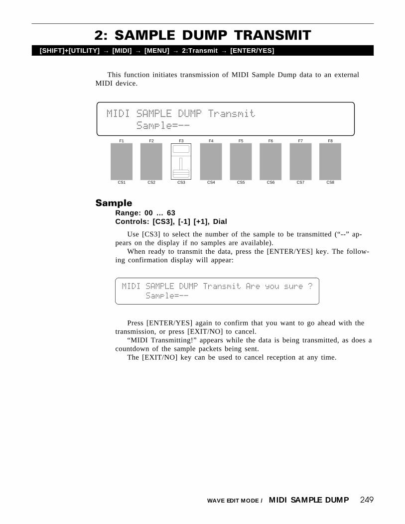
249WAVE EDIT MODE / MIDI SAMPLE DUMP
This function initiates transmission of MIDI Sample Dump data to an externalMIDI device.
2: SAMPLE DUMP TRANSMIT[SHIFT]+[UTILITY] → [MIDI] → [MENU] → 2:Transmit → [ENTER/YES]
SampleRange: 00 … 63Controls: [CS3], [-1] [+1], Dial
Use [CS3] to select the number of the sample to be transmitted (“--” ap-pears on the display if no samples are available).
When ready to transmit the data, press the [ENTER/YES] key. The follow-ing confirmation display will appear:
F1
CS1
F2
CS2
F3
CS3
F4
CS4
F5
CS5
F6
CS6
F7
CS7
F8
CS8
MIDI`SAMPLE`DUMP`Transmit```````````````
`````Sample=--``````````````````````````
MIDI`SAMPLE`DUMP`Transmit`Are`you`sure`?
`````Sample=--``````````````````````````
Press [ENTER/YES] again to confirm that you want to go ahead with thetransmission, or press [EXIT/NO] to cancel.
“MIDI Transmitting!” appears while the data is being transmitted, as does acountdown of the sample packets being sent.
The [EXIT/NO] key can be used to cancel reception at any time.

250 WAVE EDIT MODE / CARD
Loads all samples from a pre-programmed card plugged into the WAVEFORMcard slot.
WAVE CARD LOAD[SHIFT]+[UTILITY] → [CARD]
F1
CS1
F2
CS2
F3
CS3
F4
CS4
F5
CS5
F6
CS6
F7
CS7
F8
CS8
WAVE`Card`Load``````````````````````````
`````````````````Card````¥`Volatile`Mem.
ToRange: Volatile, Non-vol.Controls: [CS7], [-1] [+1], Dial
Use [CS7] to select the type of memory to which the data is to be stored(see “Wave Memory Expansion” on page 285 for additional information aboutthe memory types).
Press [ENTER/YES] to begin the card load procedure. The following confir-mation display will appear:
WAVE`Card`Load````````````Are`you`sure`?
`````````````````Card````¥`Volatile`Mem.
Press [ENTER/YES] again to confirm that you want to go ahead with thecard load operation, or press [EXIT/NO] to cancel.
When the data has been loaded , “Completed!” will appear briefly on thedisplay.
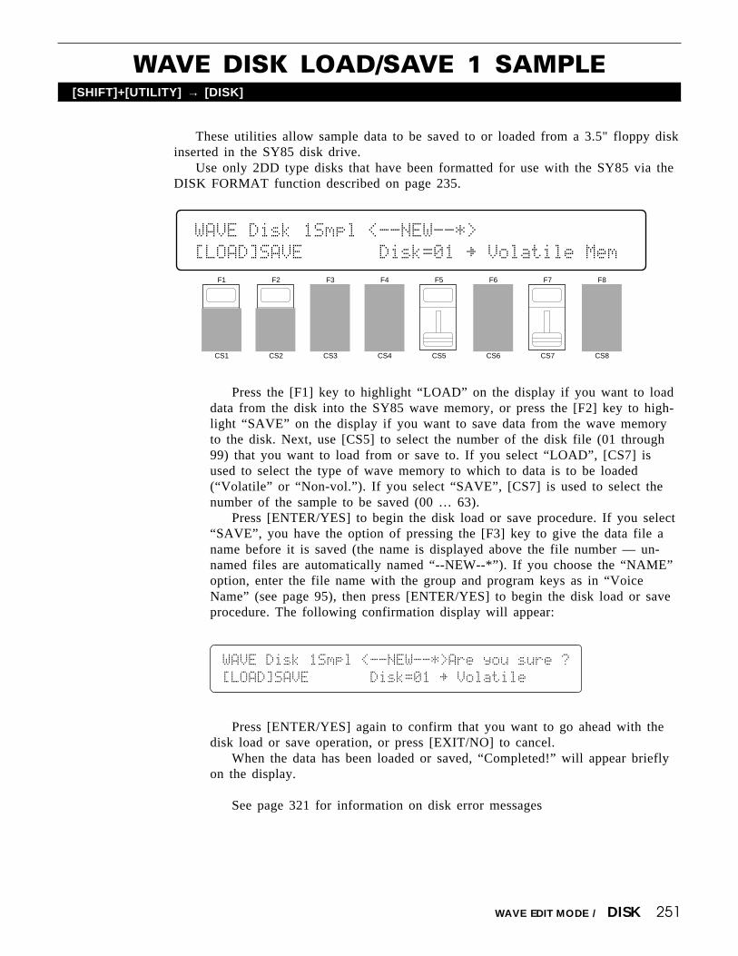
251WAVE EDIT MODE / DISK
These utilities allow sample data to be saved to or loaded from a 3.5" floppy diskinserted in the SY85 disk drive.
Use only 2DD type disks that have been formatted for use with the SY85 via theDISK FORMAT function described on page 235.
WAVE DISK LOAD/SAVE 1 SAMPLE[SHIFT]+[UTILITY] → [DISK]
Press the [F1] key to highlight “LOAD” on the display if you want to loaddata from the disk into the SY85 wave memory, or press the [F2] key to high-light “SAVE” on the display if you want to save data from the wave memoryto the disk. Next, use [CS5] to select the number of the disk file (01 through99) that you want to load from or save to. If you select “LOAD”, [CS7] isused to select the type of wave memory to which to data is to be loaded(“Volatile” or “Non-vol.”). If you select “SAVE”, [CS7] is used to select thenumber of the sample to be saved (00 … 63).
Press [ENTER/YES] to begin the disk load or save procedure. If you select“SAVE”, you have the option of pressing the [F3] key to give the data file aname before it is saved (the name is displayed above the file number — un-named files are automatically named “--NEW--*”). If you choose the “NAME”option, enter the file name with the group and program keys as in “VoiceName” (see page 95), then press [ENTER/YES] to begin the disk load or saveprocedure. The following confirmation display will appear:
WAVE`Disk`1Smpl`<--NEW--*>Are`you`sure`?
[LOAD]SAVE```````Disk=01`¥`Volatile`````
Press [ENTER/YES] again to confirm that you want to go ahead with thedisk load or save operation, or press [EXIT/NO] to cancel.
When the data has been loaded or saved, “Completed!” will appear brieflyon the display.
See page 321 for information on disk error messages
F1
CS1
F2
CS2
F3
CS3
F4
CS4
F5
CS5
F6
CS6
F7
CS7
F8
CS8
WAVE`Disk`1Smpl`<--NEW--*>``````````````
[LOAD]SAVE```````Disk=01`¥`Volatile`Mem`

252 WAVE EDIT MODE
Press and hold the [SHIFT] key at any time while in the WAVE mode to call thewave memory status display. This display shows the amount of free volatile and non-volatile memory in approximate kilobytes.
See “Wave Memory Expansion” on page 285 for information about volatile andnon-volatile wave memory.
WAVE MEMORY STATUS DISPLAY[SHIFT]+[UTILITY] → [SHIFT]
F1
CS1
F2
CS2
F3
CS3
F4
CS4
F5
CS5
F6
CS6
F7
CS7
F8
CS8
WAVE`Memory`Status``Volatile:``512kbytes
```````(Free`Area)``Non»vol.:`1024kbytes

Effects ...................................................... 254
Wave memory expansion ........................ 285
Initial data & Blank chart ........................ 289
Specifications .......................................... 319
Error messages ....................................... 320
Trouble shooting ...................................... 324
Index ........................................................ 326
APPENDIX

254 APPENDIX / EFFECTS
The SY85 features a sophisticated effect system that affords extraordinarysound-shaping potential. It includes two separate effect processors — referredto a EFFECT 1 and EFFECT 2 in this manual — that can be connected eitherin series or in parallel via the effect “Mode” parameter (page 105 for voiceeffects, page 128 for drum voice effects, page 37 for performance effects, page166 for song mode effects). In simplified block diagram form the serial andparallel modes look like this:
The SY85 has 90 different effects including reverb, early reflections, delay,pitch change, modulation and more. Any of these can be assigned to theEFFECT 1 and EFFECT 2 processors via the “EF1 Type” and “EF2 Type”parameters (page 105 for voice effects, page 128 for drum voice effects, page37 for performance effects, page 166 for song mode effects). Each effect hasup to 8 different parameters that can be edited via the EFFECT 1 PARAM-ETERS and EFFECT 2 PARAMETERS screens (page 109 for voice effects,page 135 for drum voice effects, page 44 for performance effects, page 173 forsong mode effects). A complete list of the effects and their parameters isprovided on page 274.
The 90 effects are further divided into three types:
Effects 00 - 30 ........... “Single”Effects 31 - 60 ........... “Cascade”Effects 61 - 90 ........... “Dual”
The “Single” effects are, as the name applies, single effects.
EFFECTS

255APPENDIX / EFFECTS
The “Cascade” effects actually include two effects connected in a cascadeconfiguration. Effect number 33 (Flg → Rev), for example, includes cascadedflanger and reverb.
The “Dual” effects include two effects connected in parallel.
Clearly, the possibilities for combining effect modes with effect typesallows a large variety of effect system configurations. Further versatility isprovided by a range of parameters that allow the effect signals to be combinedand mixed in a number of ways. The effect signal flow diagrams provided inthe following section should help you understand the effect signal flow andhow the various effect parameter function. Since the signal flow is somewhatdifferent in the normal voice mode and the other modes (drum voice,performance, and song), different sets of flow diagrams are provided.

256 APPENDIX / EFFECTS
Effect Signal Flow Diagrams — Voice Mode
The following diagrams illustrate effect signal flow with different effectmode and effect type combinations in the normal voice mode. In the diagramsa diamond ( ) indicates an on/off switch parameter, and a block ( ) indicatesa continuously variable level or mix parameter. Although abbreviated in thediagrams, the direct and effect output signal paths are stereo.
EFFECT MODE = off.
EFFECT MODE = serial. EFFECT 1 = single. EFFECT 2 = single.
EFFECT MODE = serial. EFFECT 1 = single. EFFECT 2 = cascade.(⊗ = effect parameter number 8)

257APPENDIX / EFFECTS
EFFECT MODE = serial. EFFECT 1 = single. EFFECT 2 = dual.
EFFECT MODE = serial. EFFECT 1 = cascade. EFFECT 2 = single.(⊗ = effect parameter number 8)
EFFECT MODE = serial. EFFECT 1 = dual. EFFECT 2 = single.
258 APPENDIX / EFFECTS
EFFECT MODE = serial. EFFECT 1 = cascade. EFFECT 2 = cascade.(⊗ = effect parameter number 8)
EFFECT MODE = serial. EFFECT 1 = cascade. EFFECT 2 = dual.(⊗ = effect parameter number 8)

259APPENDIX / EFFECTS
EFFECT MODE = serial. EFFECT 1 = dual. EFFECT 2 = cascade.(⊗ = effect parameter number 8)
EFFECT MODE = serial. EFFECT 1 = dual. EFFECT 2 = dual.

260 APPENDIX / EFFECTS
EFFECT MODE = parallel. EFFECT 1 = single. EFFECT 2 = single.
EFFECT MODE = parallel. EFFECT 1 = single. EFFECT 2 = cascade.(⊗ = effect parameter number 8)
EFFECT MODE = parallel. EFFECT 1 = single. EFFECT 2 = dual.

261APPENDIX / EFFECTS
EFFECT MODE = parallel. EFFECT 1 = cascade. EFFECT 2 = single.(⊗ = effect parameter number 8)
EFFECT MODE = parallel. EFFECT 1 = dual. EFFECT 2 = single.
EFFECT MODE = parallel. EFFECT 1 = cascade. EFFECT 2 = cascade.(⊗ = effect parameter number 8)

262 APPENDIX / EFFECTS
EFFECT MODE = parallel. EFFECT 1 = cascade. EFFECT 2 = dual.(⊗ = effect parameter number 8)
EFFECT MODE = parallel. EFFECT 1 = dual. EFFECT 2 = cascade.(⊗ = effect parameter number 8)

263APPENDIX / EFFECTS
EFFECT MODE = parallel. EFFECT 1 = dual. EFFECT 2 = dual.

264 APPENDIX / EFFECTS
Effect Signal Flow Diagrams — Drum Voice, Performance,and Song Modes
The following diagrams illustrate effect signal flow with different effectmode and effect type combinations in the drum voice, performance, and songmodes. The “Tone Generator” block has slightly different meanings in each ofthese modes:
Drum Voice“Tone Generator” corresponds to the output from a single drum/percussion instrument. The other instruments are mixed into the effectsignal path behind the “Dry1” and “Dry2” parameters or the “Switch”parameters, as indicated by a star ( ) in the diagrams.
Performance“Tone Generator” corresponds to the output from a single layer. Theother layers are mixed into the effect signal path behind the “Dry1” and“Dry2” parameters or the “Switch” parameters, as indicated by a star ( )in the diagrams.
Song“Tone Generator” corresponds to the output from a single multiinstrument. The other instruments are mixed into the effect signal pathbehind the “Dry1” and “Dry2” parameters or the “Switch” parameters, asindicated by a star ( ) in the diagrams.
In the diagrams a diamond ( ) indicates an on/off switch parameter, and ablock ( ) indicates a continuously variable level or mix parameter. Althoughabbreviated in the diagrams, the direct and effect signal paths are stereo.
EFFECT MODE = off.

265APPENDIX / EFFECTS
EFFECT MODE = serial. EFFECT 1 = single. EFFECT 2 = single.
EFFECT MODE = serial. EFFECT 1 = single. EFFECT 2 = cascade.(⊗ = effect parameter number 8)

266 APPENDIX / EFFECTS
EFFECT MODE = serial. EFFECT 1 = single. EFFECT 2 = dual.
EFFECT MODE = serial. EFFECT 1 = cascade. EFFECT 2 = single.(⊗ = effect parameter number 8)

267APPENDIX / EFFECTS
EFFECT MODE = serial. EFFECT 1 = dual. EFFECT 2 = single.
EFFECT MODE = serial. EFFECT 1 = cascade. EFFECT 2 = cascade.(⊗ = effect parameter number 8)

268 APPENDIX / EFFECTS
EFFECT MODE = serial. EFFECT 1 = cascade. EFFECT 2 = dual.(⊗ = effect parameter number 8)
EFFECT MODE = serial. EFFECT 1 = dual. EFFECT 2 = cascade.(⊗ = effect parameter number 8)

269APPENDIX / EFFECTS
EFFECT MODE = serial. EFFECT 1 = dual. EFFECT 2 = dual.
EFFECT MODE = parallel. EFFECT 1 = single. EFFECT 2 = single.

270 APPENDIX / EFFECTS
EFFECT MODE = parallel. EFFECT 1 = single. EFFECT 2 = cascade.(⊗ = effect parameter number 8)
EFFECT MODE = parallel. EFFECT 1 = single. EFFECT 2 = dual.

271APPENDIX / EFFECTS
EFFECT MODE = parallel. EFFECT 1 = cascade. EFFECT 2 = single.(⊗ = effect parameter number 8)
EFFECT MODE = parallel. EFFECT 1 = dual. EFFECT 2 = single.

272 APPENDIX / EFFECTS
EFFECT MODE = parallel. EFFECT 1 = cascade. EFFECT 2 = cascade.(⊗ = effect parameter number 8)
EFFECT MODE = parallel. EFFECT 1 = cascade. EFFECT 2 = dual.(⊗ = effect parameter number 8)

273APPENDIX / EFFECTS
EFFECT MODE = parallel. EFFECT 1 = dual. EFFECT 2 = cascade.(⊗ = effect parameter number 8)
EFFECT MODE = parallel. EFFECT 1 = dual. EFFECT 2 = dual.

274 APPENDIX / EFFECTS
The Effects & Their Parameters* Parameters with “ ” in the QE column are editable in the Quick Edit modes.B
“Single” Effects
• 00 : ThroughNo. PARAMETER RANGE QE1~8 — —
B
B
B
B
• 01 : Rev. Hall1No. PARAMETER RANGE QE1 Rev.Time [s] 0.3 ~ 30.0s2 High 0.1 ~ 1.53 Diffusion 0 ~ 104 Density 0 ~ 45 ER/Rev Bal [%] 0 ~ 100%6 Low Gain [dB] -12 ~ +12dB7 High Gain [dB] -12 ~ +12dB8 LPF [kHz] 1.0 ~ 16.0kHz, thru
B
B
B
B
• 02 : Rev. Hall2No. PARAMETER RANGE QE1 Rev.Time [s] 0.3 ~ 30.0s2 High 0.1 ~ 1.53 Diffusion 0 ~ 104 Init Dly [ms] 0 ~ 150ms5 Rev.Dly [ms] 0 ~ 100ms6 Density 0 ~ 47 ER/Rev Bal [%] 0 ~ 100%8 LPF [kHz] 1.0 ~ 16.0kHz, thru
B
B
B
B
• 06 : Rev. Stage1, 07 : Rev. Stage2No. PARAMETER RANGE QE1 Rev.Time [s] 0.3 ~ 30.0s2 High 0.1 ~ 1.53 Diffusion 0 ~ 104 Init Dly [ms] 0 ~ 60ms5 Rev.Dly [ms] 0 ~ 30ms6 Density 0 ~ 47 ER/Rev Bal [%] 0 ~ 100%8 LPF [kHz] 1.0 ~ 16.0kHz, thru
B
B
B
B
• 03 : Rev. Room1, 04 : Rev. Room2, 05 : Rev. Room3No. PARAMETER RANGE QE1 Rev.Time [s] 0.3 ~ 30.0s2 High 0.1 ~ 1.53 Diffusion 0 ~ 104 Init Dly [ms] 0 ~ 200ms5 Rev.Dly [ms] 0 ~ 130ms6 Density 0 ~ 47 ER/Rev Bal [%] 0 ~ 100%8 LPF [kHz] 1.0 ~ 16.0kHz, thru
B
B
B
B
• 08 : Rev. PlateNo. PARAMETER RANGE QE1 Rev.Time [s] 0.3 ~ 30.0s2 High 0.1 ~ 1.53 Diffusion 0 ~ 104 Init Dly [ms] 0 ~ 200ms5 Rev.Dly [ms] 0 ~ 200ms6 Density 0 ~ 47 ER/Rev Bal [%] 0 ~ 100%8 LPF [kHz] 1.0 ~ 16.0kHz, thru
B
B
B
B
• 09 : Rev. WhRoom, 10 : Rev. Tunnel,11 : Rev. Canyon, 12 : Rev. Basmnt
No. PARAMETER RANGE QE1 Rev.Time [s] 0.3 ~ 30.0s2 High 0.1 ~ 1.53 Diffusion 0 ~ 104 Width [m] 0.5 ~ 23.6m5 Height [m] 0.5 ~ 23.6m6 Depth [m] 0.5 ~ 23.6m7 Wall Vary 0 ~ 308 LPF [kHz] 1.0 ~ 16.0kHz, thru
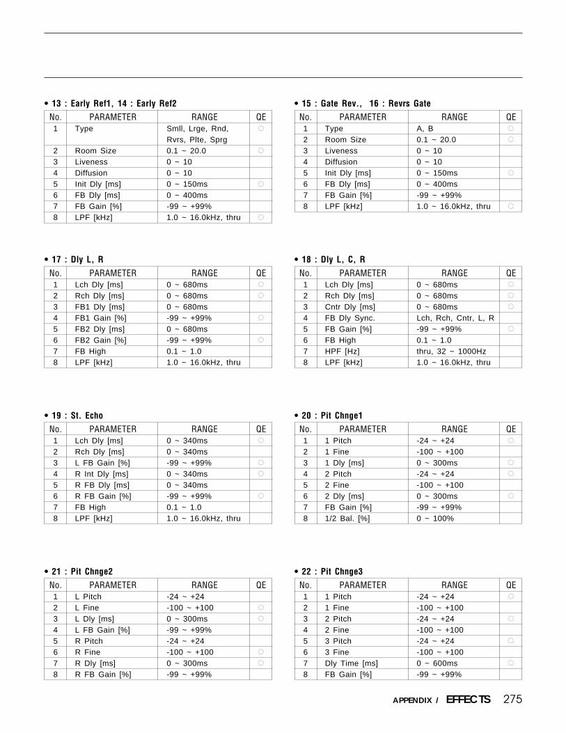
275APPENDIX / EFFECTS
B
B
B
B
• 15 : Gate Rev., 16 : Revrs GateNo. PARAMETER RANGE QE1 Type A, B2 Room Size 0.1 ~ 20.03 Liveness 0 ~ 104 Diffusion 0 ~ 105 Init Dly [ms] 0 ~ 150ms6 FB Dly [ms] 0 ~ 400ms7 FB Gain [%] -99 ~ +99%8 LPF [kHz] 1.0 ~ 16.0kHz, thru
B
B
B
B
• 13 : Early Ref1, 14 : Early Ref2No. PARAMETER RANGE QE1 Type Smll, Lrge, Rnd,
Rvrs, Plte, Sprg2 Room Size 0.1 ~ 20.03 Liveness 0 ~ 104 Diffusion 0 ~ 105 Init Dly [ms] 0 ~ 150ms6 FB Dly [ms] 0 ~ 400ms7 FB Gain [%] -99 ~ +99%8 LPF [kHz] 1.0 ~ 16.0kHz, thru
B
B
B
B
• 18 : Dly L, C, R
No. PARAMETER RANGE QE1 Lch Dly [ms] 0 ~ 680ms2 Rch Dly [ms] 0 ~ 680ms3 Cntr Dly [ms] 0 ~ 680ms4 FB Dly Sync. Lch, Rch, Cntr, L, R5 FB Gain [%] -99 ~ +99%6 FB High 0.1 ~ 1.07 HPF [Hz] thru, 32 ~ 1000Hz8 LPF [kHz] 1.0 ~ 16.0kHz, thru
B
B
B
B
• 17 : Dly L, R
No. PARAMETER RANGE QE1 Lch Dly [ms] 0 ~ 680ms2 Rch Dly [ms] 0 ~ 680ms3 FB1 Dly [ms] 0 ~ 680ms4 FB1 Gain [%] -99 ~ +99%5 FB2 Dly [ms] 0 ~ 680ms6 FB2 Gain [%] -99 ~ +99%7 FB High 0.1 ~ 1.08 LPF [kHz] 1.0 ~ 16.0kHz, thru
B
B
B
B
• 20 : Pit Chnge1No. PARAMETER RANGE QE1 1 Pitch -24 ~ +242 1 Fine -100 ~ +1003 1 Dly [ms] 0 ~ 300ms4 2 Pitch -24 ~ +245 2 Fine -100 ~ +1006 2 Dly [ms] 0 ~ 300ms7 FB Gain [%] -99 ~ +99%8 1/2 Bal. [%] 0 ~ 100%
B
B
B
B
• 19 : St. EchoNo. PARAMETER RANGE QE1 Lch Dly [ms] 0 ~ 340ms2 Rch Dly [ms] 0 ~ 340ms3 L FB Gain [%] -99 ~ +99%4 R Int Dly [ms] 0 ~ 340ms5 R FB Dly [ms] 0 ~ 340ms6 R FB Gain [%] -99 ~ +99%7 FB High 0.1 ~ 1.08 LPF [kHz] 1.0 ~ 16.0kHz, thru
B
B
B
B
• 22 : Pit Chnge3No. PARAMETER RANGE QE1 1 Pitch -24 ~ +242 1 Fine -100 ~ +1003 2 Pitch -24 ~ +244 2 Fine -100 ~ +1005 3 Pitch -24 ~ +246 3 Fine -100 ~ +1007 Dly Time [ms] 0 ~ 600ms8 FB Gain [%] -99 ~ +99%
B
B
B
B
• 21 : Pit Chnge2No. PARAMETER RANGE QE1 L Pitch -24 ~ +242 L Fine -100 ~ +1003 L Dly [ms] 0 ~ 300ms4 L FB Gain [%] -99 ~ +99%5 R Pitch -24 ~ +246 R Fine -100 ~ +1007 R Dly [ms] 0 ~ 300ms8 R FB Gain [%] -99 ~ +99%
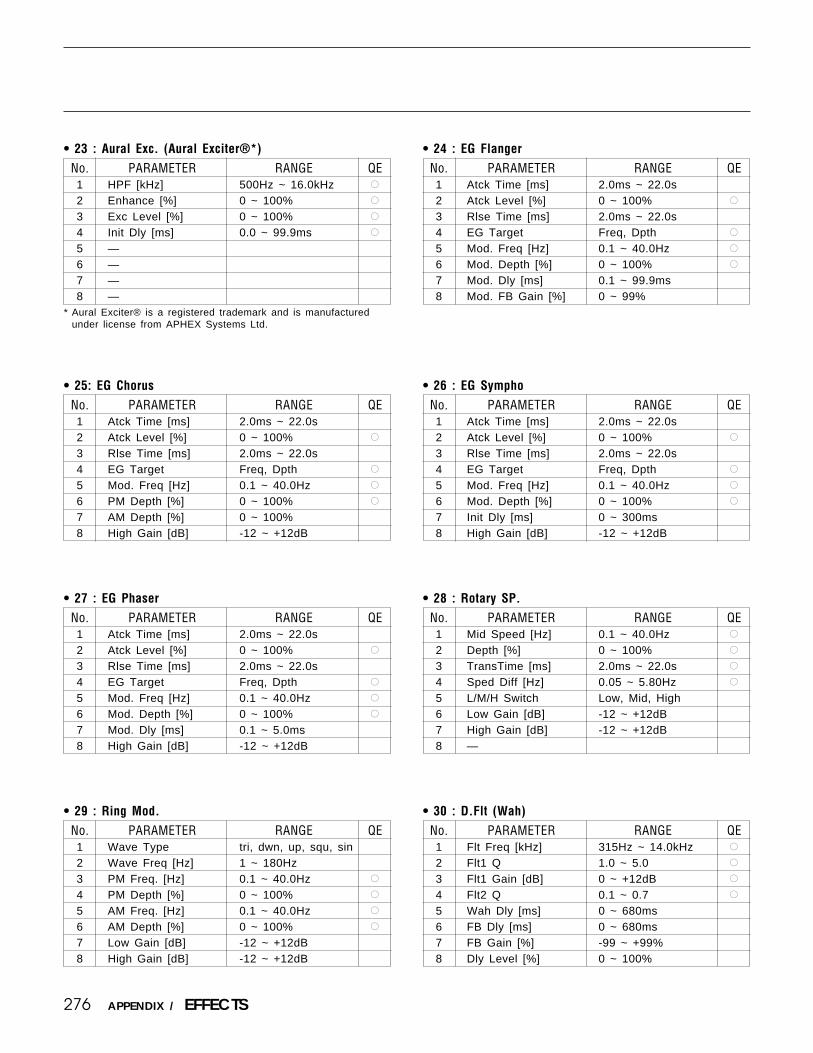
276 APPENDIX / EFFECTS
B
B
B
B
• 24 : EG FlangerNo. PARAMETER RANGE QE1 Atck Time [ms] 2.0ms ~ 22.0s2 Atck Level [%] 0 ~ 100%3 Rlse Time [ms] 2.0ms ~ 22.0s4 EG Target Freq, Dpth5 Mod. Freq [Hz] 0.1 ~ 40.0Hz6 Mod. Depth [%] 0 ~ 100%7 Mod. Dly [ms] 0.1 ~ 99.9ms8 Mod. FB Gain [%] 0 ~ 99%
• 23 : Aural Exc. (Aural Exciter®*)No. PARAMETER RANGE QE1 HPF [kHz] 500Hz ~ 16.0kHz2 Enhance [%] 0 ~ 100%3 Exc Level [%] 0 ~ 100%4 Init Dly [ms] 0.0 ~ 99.9ms5 —6 —7 —8 —
B
B
B
B
* Aural Exciter® is a registered trademark and is manufacturedunder license from APHEX Systems Ltd.
B
B
B
B
B
B
B
B
• 25: EG ChorusNo. PARAMETER RANGE QE1 Atck Time [ms] 2.0ms ~ 22.0s2 Atck Level [%] 0 ~ 100%3 Rlse Time [ms] 2.0ms ~ 22.0s4 EG Target Freq, Dpth5 Mod. Freq [Hz] 0.1 ~ 40.0Hz6 PM Depth [%] 0 ~ 100%7 AM Depth [%] 0 ~ 100%8 High Gain [dB] -12 ~ +12dB
• 26 : EG SymphoNo. PARAMETER RANGE QE1 Atck Time [ms] 2.0ms ~ 22.0s2 Atck Level [%] 0 ~ 100%3 Rlse Time [ms] 2.0ms ~ 22.0s4 EG Target Freq, Dpth5 Mod. Freq [Hz] 0.1 ~ 40.0Hz6 Mod. Depth [%] 0 ~ 100%7 Init Dly [ms] 0 ~ 300ms8 High Gain [dB] -12 ~ +12dB
B
B
B
B
• 28 : Rotary SP.No. PARAMETER RANGE QE1 Mid Speed [Hz] 0.1 ~ 40.0Hz2 Depth [%] 0 ~ 100%3 TransTime [ms] 2.0ms ~ 22.0s4 Sped Diff [Hz] 0.05 ~ 5.80Hz5 L/M/H Switch Low, Mid, High6 Low Gain [dB] -12 ~ +12dB7 High Gain [dB] -12 ~ +12dB8 —
B
B
B
B
• 27 : EG PhaserNo. PARAMETER RANGE QE1 Atck Time [ms] 2.0ms ~ 22.0s2 Atck Level [%] 0 ~ 100%3 Rlse Time [ms] 2.0ms ~ 22.0s4 EG Target Freq, Dpth5 Mod. Freq [Hz] 0.1 ~ 40.0Hz6 Mod. Depth [%] 0 ~ 100%7 Mod. Dly [ms] 0.1 ~ 5.0ms8 High Gain [dB] -12 ~ +12dB
B
B
B
B
• 30 : D.Flt (Wah)No. PARAMETER RANGE QE1 Flt Freq [kHz] 315Hz ~ 14.0kHz2 Flt1 Q 1.0 ~ 5.03 Flt1 Gain [dB] 0 ~ +12dB4 Flt2 Q 0.1 ~ 0.75 Wah Dly [ms] 0 ~ 680ms6 FB Dly [ms] 0 ~ 680ms7 FB Gain [%] -99 ~ +99%8 Dly Level [%] 0 ~ 100%
B
B
B
B
• 29 : Ring Mod.No. PARAMETER RANGE QE1 Wave Type tri, dwn, up, squ, sin2 Wave Freq [Hz] 1 ~ 180Hz3 PM Freq. [Hz] 0.1 ~ 40.0Hz4 PM Depth [%] 0 ~ 100%5 AM Freq. [Hz] 0.1 ~ 40.0Hz6 AM Depth [%] 0 ~ 100%7 Low Gain [dB] -12 ~ +12dB8 High Gain [dB] -12 ~ +12dB

277APPENDIX / EFFECTS
“Cascade” Effects
B
B
B
B
• 32 : Echo → RevNo. PARAMETER RANGE QE1 Lch Dly [ms] 0 ~ 200ms2 L FB Gain [%] -99 ~ +99%3 Rch Dly [ms] 0 ~ 200ms4 R FB Gain [%] -99 ~ +99%5 Rev. Time [s] 0.3 ~ 30.0s6 High 0.1 ~ 1.57 LPF [kHz] 1.0 ~ 16.0kHz, thru8 Rev Level [%] 0 ~ 100%
• 31 : Dly → RevNo. PARAMETER RANGE QE1 Lch Dly [ms] 0 ~ 400ms2 Rch Dly [ms] 0 ~ 400ms3 FB Gain [%] -99 ~ +99%4 Rev. Time [s] 0.3 ~ 30.0s5 High 0.1 ~ 1.56 ER/Rev Bal [%] 0 ~ 100%7 LPF [kHz] 1.0 ~ 16.0kHz, thru8 Rev Level [%] 0 ~ 100%
B
B
B
B
B
B
B
B
B
B
B
B
• 33 : Flg → Rev
No. PARAMETER RANGE QE1 Mod. Freq [Hz] 0.1 ~ 40.0Hz2 Mod. Depth [%] 0 ~ 100%3 Mod. Dly [ms] 0.1 ~ 30.0ms4 Mod. FB Gain [%] 0 ~ 99%5 Rev. Time [s] 0.3 ~ 30.0s6 High 0.1 ~ 1.57 LPF [kHz] 1.0 ~ 16.0kHz, thru8 Rev Level [%] 0 ~ 100%
• 34 : Cho → Rev
No. PARAMETER RANGE QE1 Mod. Freq [Hz] 0.1 ~ 40.0Hz2 PM Depth [%] 0 ~ 100%3 AM Depth [%] 0 ~ 100%4 Rev. Time [s] 0.3 ~ 30.0s5 High 0.1 ~ 1.56 Init Dly [ms] 0 ~ 200ms7 LPF [kHz] 1.0 ~ 16.0kHz, thru8 Rev Level [%] 0 ~ 100%
B
B
B
B
• 36 : Pha → RevNo. PARAMETER RANGE QE1 Mod. Freq [Hz] 0.1 ~ 40.0Hz2 Mod. Depth [%] 0 ~ 100%3 Mod. Dly [ms] 0.1 ~ 5.0ms4 Rev. Time [s] 0.3 ~ 30.0s5 High 0.1 ~ 1.56 Init Dly [ms] 0 ~ 200ms7 LPF [kHz] 1.0 ~ 16.0kHz, thru8 Rev Level [%] 0 ~ 100%
B
B
B
B
• 35 : Sym → RevNo. PARAMETER RANGE QE1 Mod. Freq [Hz] 0.1 ~ 40.0Hz2 Mod. Depth [%] 0 ~ 100%3 High Gain [dB] -12 ~ +12dB4 Rev. Time [s] 0.3 ~ 30.0s5 High 0.1 ~ 1.56 Init Dly [ms] 0 ~ 200ms7 LPF [kHz] 1.0 ~ 16.0kHz, thru8 Rev Level [%] 0 ~ 100%

278 APPENDIX / EFFECTS
B
B
B
B
• 37 : Pit → RevNo. PARAMETER RANGE QE1 L Pitch -24 ~ +242 L Fine -100 ~ +1003 R Pitch -24 ~ +244 R Fine -100 ~ +1005 Rev. Time [s] 0.3 ~ 30.0s6 High 0.1~ 1.57 LPF [kHz] 1.0 ~ 16.0kHz, thru8 Rev Level [%] 0 ~ 100%
B
B
B
B
• 38 : Exc → Rev (Aural Exciter®*)No. PARAMETER RANGE QE1 HPF [kHz] 500Hz ~ 16.0kHz2 Enhance [%] 0 ~ 100%3 Exc Level [%] 0 ~ 100%4 Rev. Time [s] 0.3 ~ 30.0s5 High 0 .1~ 1.56 Init Dly [ms] 0 ~ 200ms7 LPF [kHz] 1.0 ~ 16.0kHz, thru8 Rev Level [%] 0 ~ 100%
* Aural Exciter® is a registered trademark and is manufacturedunder license from APHEX Systems Ltd.
B
B
B
B
B
B
B
B
• 39 : Dist → Rev
No. PARAMETER RANGE QE1 Dist. Level [%] 0 ~ 100%2 Mid. Freq [kHz] 315Hz ~ 6.3kHz3 Mid. Gain [dB] -12 ~ +12dB4 Trbl Gain [dB] -12 ~ +12dB5 Rev. Time [s] 0 .3~ 30.0s6 High 0.1 ~ 1.57 LPF [kHz] 1.0 ~ 16.0kHz, thru8 Rev Level [%] 0 ~ 100%
• 40 : Pan → Rev
No. PARAMETER RANGE QE1 Type L→R, R→L, L<>R2 Speed 1 ~ 523 Fade In [%] -100 ~ +100%4 L/R Depth [%] 0 ~ 100%5 Rev. Time [s] 0 .3~ 30.0s6 High 0.1 ~ 1.57 LPF [kHz] 1.0 ~ 16.0kHz, thru8 Rev Level [%] 0 ~ 100%
B
B
B
B
• 42 : Cho → DlyNo. PARAMETER RANGE QE1 Mod. Freq [Hz] 0.1 ~ 40.0Hz2 PM Depth [%] 0 ~ 100%3 AM Depth [%] 0 ~ 100%4 High Gain [dB] -12 ~ +12dB5 Lch Dly [ms] 0 ~ 600ms6 Rch Dly [ms] 0 ~ 600ms7 FB Gain [%] -99 ~ +99%8 Dly Level [%] 0 ~ 100%
B
B
B
B
• 41 : Flg → DlyNo. PARAMETER RANGE QE1 Mod. Freq [Hz] 0.1 ~ 40.0Hz2 Mod. Depth [%] 0 ~ 100%3 Mod. Dly [ms] 0.1 ~ 30.0ms4 Mod. FB Gain [%] 0 ~ 99%5 Lch Dly [ms] 0 ~ 600ms6 Rch Dly [ms] 0 ~ 600ms7 FB Gain [%] -99 ~ +99%8 Dly Level [%] 0 ~ 100%
B
B
B
B
• 44 : Pha → DlyNo. PARAMETER RANGE QE1 Mod. Freq [Hz] 0.1 ~ 40.0Hz2 Mod. Depth [%] 0 ~ 100%3 Mod. Dly [ms] 0.1 ~ 5.0ms4 High Gain [dB] 0.1 ~ +12dB5 Lch Dly [ms] 0 ~ 600ms6 Rch Dly [ms] 0 ~ 600ms7 FB Gain [%] -99 ~ +99%8 Dly Level [%] 0 ~ 100%
B
B
B
B
• 43 : Sym → DlyNo. PARAMETER RANGE QE1 Mod. Freq [Hz] 0.1 ~ 40.0Hz2 Mod Depth [%] 0 ~ 100%3 — —4 High Gain [dB] -12 ~ +12dB5 Lch Dly [ms] 0 ~ 600ms6 Rch Dly [ms] 0 ~ 600ms7 FB Gain [%] -99 ~ +99%8 Dly Level [%] 0 ~ 100%

279APPENDIX / EFFECTS
B
B
B
B
• 45 : Pit → DlyNo. PARAMETER RANGE QE1 L Pitch -24 ~ +242 L Fine -100 ~ +1003 R Pitch -24 ~ +244 R Fine -100 ~ +1005 Lch Dly [ms] 0 ~ 600ms6 Rch Dly [ms] 0 ~ 600ms7 FB Gain [%] -99 ~ +99%8 Dly Level [%] 0 ~ 100%
B
B
B
B
• 46 : Exc → Dly (Aural Exciter®*)No. PARAMETER RANGE QE1 HPF [kHz] 500Hz ~ 16kHz2 Enhance [%] 0 ~ 100%3 Exc Level [%] 0 ~ 100%4 Init Dly [ms] 0.0 ~ 80.0ms5 Lch Dly [ms] 0 ~ 600ms6 Rch Dly [ms] 0 ~ 600ms7 FB Gain [%] -99 ~ +99%8 Dly Level [%] 0 ~ 100%
* Aural Exciter® is a registered trademark and is manufacturedunder license from APHEX Systems Ltd.
B
B
B
B
• 52 : EQ → ERNo. PARAMETER RANGE QE1 Low Freq [kHz] 32Hz ~ 2.0kHz2 Low Gain [dB] -12 ~ +12dB3 High Frq [kHz] 500Hz ~ 16.0kHz4 High Gain [dB] -12 ~ +12dB5 Type Smll, Lrge, Rnd,
Rvrs, Plte, Sprg6 Diffusion 0 ~ 107 Init Dly [ms] 0 ~ 200ms8 ER Level [%] 0 ~ 100%
B
B
B
B
• 51 : EQ → Rev2No. PARAMETER RANGE QE1 Low Freq [kHz] 32Hz ~ 2.0kHz2 Low Gain [dB] -12 ~ +12dB3 High Frq [kHz] 500Hz ~ 16.0kHz4 High Gain [dB] -12 ~ +12dB5 Rev. Time [s] 0.3 ~ 30.0s6 High 0.1 ~ 1.57 Init Dly [ms] 0 ~ 250ms8 Rev Level [%] 0 ~ 100%
B
B
B
B
• 50 : EQ → Rev1No. PARAMETER RANGE QE1 Low Freq [kHz] 32Hz ~ 2.0kHz2 Low Gain [dB] -12 ~ +12dB3 High Frq. [kHz] 500Hz ~ 16.0kHz4 High Gain [dB] -12 ~ +12dB5 Rev. Time [s] 0.3 ~ 30.0s6 High 0.1 ~ 1.57 ER/Rev Bal [%] 0 ~ 100%8 Rev Level [%] 0 ~ 100%
B
B
B
B
• 49 : Dist → EchoNo. PARAMETER RANGE QE1 Dist. Level [%] 0 ~ 100%2 Mid. Freq [kHz] 315Hz ~ 6.3kHz3 Mid. Gain [dB] -12 ~ +12dB4 Trbl Gain [dB] -12 ~ +12dB5 Lch Dly [ms] 0 ~ 340ms6 Rch Dly [ms] 0 ~ 340ms7 FB Gain [%] -99 ~ +99%8 Echo Level [%] 0 ~ 100%
B
B
B
B
B
B
B
B
• 47 : Dist → Dly
No. PARAMETER RANGE QE1 Dist. Level [%] 0 ~ 100%2 Mid. Freq [kHz] 315Hz ~ 6.3kHz3 Mid. Gain [dB] -12 ~ +12dB4 Trbl Gain [dB] -12 ~ +12dB5 Lch Dly [ms] 0 ~ 680ms6 Rch Dly [ms] 0 ~ 680ms7 FB Gain [%] -99 ~ +99%8 Dly Level [%] 0 ~ 100%
• 48 : Pan → Dly
No. PARAMETER RANGE QE1 Type L→R, R→L, L<>R2 Speed 1 ~ 523 Fade In [%] -100 ~ +100%4 L/R Depth [%] 0 ~ 100%5 Lch Dly [ms] 0~ 680ms6 Rch Dly [ms] 0~ 680ms7 FB Gain [%] -99 ~ +99%8 Dly Level [%] 0 ~ 100%

280 APPENDIX / EFFECTS
B
B
B
B
• 53 : EQ → DlyNo. PARAMETER RANGE QE1 Low Freq [kHz] 32Hz ~ 2.0kHz2 Low Gain [dB] -12 ~ +12dB3 High Frq [kHz] 500Hz ~ 16.0kHz4 High Gain [dB] -12 ~ +12dB5 Lch Dly [ms] 0 ~ 680ms6 Rch Dly [ms] 0 ~ 680ms7 FB Gain [%] -99 ~ +99%8 Dly Level [%] 0 ~ 100%
B
B
B
B
B
B
B
B
B
B
B
B
• 55 : EQ → Flg
No. PARAMETER RANGE QE1 Low Freq [kHz] 32Hz ~ 2.0kHz2 Low Gain [dB] -12 ~ +12dB3 High Frq [kHz] 500Hz ~ 16.0kHz4 High Gain [dB] -12 ~ +12dB5 Mod. Freq [Hz] 0.1 ~ 40.0Hz6 Mod. Depth [%] 0 ~ 100%7 Mod. FB Gain [%] 0 ~ 99%8 Flg Level [%] 0 ~ 100%
• 56 : EQ → Cho
No. PARAMETER RANGE QE1 Low Freq [kHz] 32Hz ~ 2.0kHz2 Low Gain [dB] -12 ~ +12dB3 High Frq [kHz] 500Hz ~ 16.0kHz4 High Gain [dB] -12 ~ +12dB5 Mod. Freq [Hz] 0.1 ~ 40.0Hz6 PM Depth [%] 0 ~ 100%7 AM Depth [%] 0 ~ 100%8 Cho Level [%] 0 ~ 100%
B
B
B
B
• 58 : EQ → PhaNo. PARAMETER RANGE QE1 Low Freq [kHz] 32Hz ~ 2.0kHz2 Low Gain [dB] -12 ~ +12dB3 High Frq [kHz] 500Hz ~ 16.0kHz4 High Gain [dB] -12 ~ +12dB5 Mod. Freq [Hz] 0.1 ~ 40.0Hz6 Mod. Depth [%] 0 ~ 100%7 Mod. Dly [ms] 0.1 ~ 5.0ms8 Pha Level [%] 0 ~ 100%
B
B
B
B
• 57 : EQ → SymNo. PARAMETER RANGE QE1 Low Freq [kHz] 32Hz ~ 2.0kHz2 Low Gain [dB] -12 ~ +12dB3 High Frq [kHz] 500Hz ~ 16.0kHz4 High Gain [dB] -12 ~ +12dB5 Mod. Freq [Hz] 0.1 ~ 40.0Hz6 Mod. Depth [%] 0 ~ 100%7 Init Dly [ms] 0 ~ 300ms8 Sym Level [%] 0 ~ 100%
B
B
B
B
• 60 : EQ → PanNo. PARAMETER RANGE QE1 Low Freq [kHz] 32Hz ~ 2.0kHz2 Low Gain [dB] -12 ~ +12dB3 High Frq [kHz] 500Hz ~ 16.0kHz4 High Gain [dB] -12 ~ +12dB5 Type L→R, R→L, L<>R6 Speed 1 ~ 527 Fade In [%] -100 ~ +100%8 L/R Depth [%] 0 ~ 100%
B
B
B
B
• 59 : EQ → PitNo. PARAMETER RANGE QE1 Low Freq [kHz] 32Hz ~ 2.0kHz2 Low Gain [dB] -12 ~ +12dB3 High Frq [kHz] 500Hz ~ 16.0kHz4 High Gain [dB] -12 ~ +12dB5 L Fine -999 ~ +9996 R Fine -999 ~ +9997 Init Dly [ms] 0 ~ 300ms8 Pit Level [%] 0 ~ 100%
• 54 : EQ → EchoNo. PARAMETER RANGE QE1 Low Freq [kHz] 32Hz ~ 2.0kHz2 Low Gain [dB] -12 ~ +12dB3 High Frq [kHz] 500Hz ~ 16.0kHz4 High Gain [dB] -12 ~ +12dB5 Lch Dly [ms] 0 ~ 340ms6 Rch Dly [ms] 0 ~ 340ms7 FB Gain [%] -99 ~ +99%8 Echo Level [%] 0 ~ 100%

281APPENDIX / EFFECTS
“Dual” Effects
B
B
B
B
• 62 : Echo & RevNo. PARAMETER RANGE QE1 Lch Dly [ms] 0 ~ 200ms2 L FB Gain [%] -99 ~ +99%3 Rch Dly [ms] 0 ~ 200ms4 R FB Gain [%] -99 ~ +99%5 Rev. Time [s] 0.3 ~ 30.0s6 High 0.1 ~ 1.57 ER/Rev Bal [%] 0 ~ 100%8 LPF [kHz] 1.0 ~ 16.0kHz, thru
• 61 : Hall & PlateNo. PARAMETER RANGE QE1 Rev. Time [s] 0.3 ~ 30.0s2 High 0.1 ~ 1.53 Diffusion 0 ~ 104 LPF [kHz] 1.0 ~ 16.0kHz, thru5 Rev. Time [s] 0.3 ~ 30.0s6 High 0.1 ~ 1.57 Diffusion 0 ~ 108 LPF [kHz] 1.0 ~ 16.0kHz, thru
B
B
B
B
B
B
B
B
B
B
B
B
• 63 : Flg & Rev
No. PARAMETER RANGE QE1 Mod. Freq [Hz] 0.1 ~ 40.0Hz2 Mod. Depth [%] 0 ~ 100%3 Mod Dly [ms] 0.1 ~ 30.0ms4 Mod. FB Gain [%] 0 ~ 99%5 Rev. Time [s] 0.3 ~ 30.0s6 High 0.1 ~ 1.57 Init Dly [ms] 0 ~ 200ms8 LPF [kHz] 1.0 ~ 16.0kHz, thru
• 64 : Cho & Rev
No. PARAMETER RANGE QE1 Mod. Freq [Hz] 0.1 ~ 40.0Hz2 PM Depth [%] 0 ~ 100%3 AM Depth [%] 0 ~ 100%4 High Gain [dB] -12 ~ +12dB5 Rev. Time [s] 0.3 ~ 30.0s6 High 0.1 ~ 1.57 Init Dly [ms] 0 ~ 200ms8 LPF [kHz] 1.0 ~ 16.0kHz, thru
B
B
B
B
• 66 : Pha & RevNo. PARAMETER RANGE QE1 Mod. Freq [Hz] 0.1 ~ 40.0Hz2 Mod. Depth [%] 0 ~ 100%3 Mod. Dly [ms] 0.1 ~ 5.0ms4 High Gain [dB] -12 ~ +12dB5 Rev. Time [s] 0.3 ~ 30.0s6 High 0.1 ~ 1.57 Init Dly [ms] 0 ~ 200ms8 LPF [kHz] 1.0 ~ 16.0kHz, thru
B
B
B
B
• 65 : Sym & RevNo. PARAMETER RANGE QE1 Mod. Freq [Hz] 0.1 ~ 40.0Hz2 Mod. Depth [%] 0 ~ 100%3 —4 High Gain [dB] -12 ~ +12dB5 Rev. Time [s] 0.3 ~ 30.0s6 High 0.1 ~ 1.57 Init Dly [ms] 0 ~ 200ms8 LPF [kHz] 1.0 ~ 16.0kHz, thru

282 APPENDIX / EFFECTS
B
B
B
B
• 67 : Pit & RevNo. PARAMETER RANGE QE1 L Pitch -24 ~ +242 L Fine -100 ~ +1003 R Pitch -24 ~ +244 R Fine -100 ~ +1005 Rev. Time [s] 0.3 ~ 30.0s6 High 0.1 ~ 1.57 Init Dly [ms] 0 ~ 200ms8 LPF [kHz] 1.0 ~ 16.0kHz, thru
B
B
B
B
• 68 : Exc & Rev (Aural Exciter®*)No. PARAMETER RANGE QE1 HPF [kHz] 500Hz ~ 16.0kHz2 Enhance [%] 0 ~ 100%3 Exc Level [%] 0 ~ 100%4 Init Dly [ms] 0.0 ~ 50.0ms5 Rev. Time [s] 0.3 ~ 30.0s6 High 0.1 ~ 1.57 Init Dly [ms] 0 ~ 200ms8 LPF [kHz] 1.0 ~ 16.0kHz, thru
* Aural Exciter® is a registered trademark and is manufacturedunder license from APHEX Systems Ltd.
B
B
B
B
B
B
B
B
• 69 : Dist & RevNo. PARAMETER RANGE QE1 Dist. Level [%] 0 ~ 100%2 Mid. Freq [kHz] 315Hz ~ 6.3kHz3 Mid. Gain [dB] -12 ~ +12dB4 Trbl Gain [dB] -12 ~ +12dB5 Rev. Time [s] 0.3 ~ 30.0s6 High 0.1 ~ 1.57 Init Dly [ms] 0 ~ 200ms8 LPF [kHz] 1.0 ~ 16.0kHz, thru
• 70 : Pan & RevNo. PARAMETER RANGE QE1 Pan Type L→R, R→L, L<>R2 Speed 1 ~ 523 Fade In [%] -100 ~ +100%4 L/R Depth [%] 0 ~ 100%5 Rev. Time [s] 0.3 ~ 30.0s6 High 0.1 ~ 1.57 Init Dly [ms] 0 ~ 150ms8 LPF [kHz] 1.0 ~ 16.0kHz, thru
B
B
B
B
• 72 : Dly & DlyNo. PARAMETER RANGE QE1 Lch Dly [ms] 0 ~ 340ms2 Rch Dly [ms] 0 ~ 340ms3 FB Gain [%] -99 ~ +99%4 High Gain [%] -12 ~ +12dB5 Lch Dly [ms] 0 ~ 340ms6 Rch Dly [ms] 0 ~ 340ms7 FB Gain [%] -99 ~ +99%8 High Gain [dB] -12 ~ +12dB
B
B
B
B
• 71 : Dly & RevNo. PARAMETER RANGE QE1 Lch Dly [ms] 0 ~ 400ms2 Rch Dly [ms] 0 ~ 400ms3 FB Gain [%] -99 ~ +99%4 Rev. Time [s] 0.3 ~ 30.0s5 High 0.1 ~ 1.56 Diffusion 0 ~ 107 ER/Rev Bal [%] 0 ~ 100%8 LPF [kHz] 1.0 ~ 16.0kHz, thru
B
B
B
B
• 74 : Cho & DlyNo. PARAMETER RANGE QE1 Mod. Freq [Hz] 0.1 ~ 40.0Hz2 PM Depth [%] 0 ~ 100%3 AM Depth [%] 0 ~ 100%4 High Gain [dB] -12 ~ +12dB5 Lch Dly [ms] 0 ~ 600ms6 Rch Dly [ms] 0 ~ 600ms7 FB Gain [%] -99 ~ +99%8 High Gain [dB] -12 ~ +12dB
B
B
B
B
• 73 : Flg & DlyNo. PARAMETER RANGE QE1 Mod. Freq [Hz] 0.1 ~ 40.0Hz2 Mod. Depth [ms] 0 ~ 100%3 Mod. Dly [ms] 0.1 ~ 30.0ms4 Mod. FB Gain [%] 0 ~ 99%5 Lch Dly [ms] 0 ~ 600ms6 Rch Dly [ms] 0 ~ 600ms7 FB Gain [%] -99 ~ +99%8 High Gain [dB] -12 ~ +12dB

283APPENDIX / EFFECTS
B
B
B
B
• 75 : Sym & DlyNo. PARAMETER RANGE QE1 Mod. Freq [Hz] 0.1 ~ 40.0Hz2 Mod. Depth [%] 0 ~ 100%3 — —4 High Gain [dB] -12 ~ +12dB5 Lch Dly [ms] 0 ~ 600ms6 Rch Dly [ms] 0 ~ 600ms7 FB Gain [%] -99 ~ +99%8 High Gain [dB] -12 ~ +12dB
B
B
B
B
• 76 : Pha & DlyNo. PARAMETER RANGE QE1 Mod. Freq [Hz] 0.1 ~ 40.0Hz2 Mod Depth [%] 0 ~ 100%3 Mod Dly [ms] 0.1 ~ 5.0ms4 High Gain [dB] -12 ~ +12dB5 Lch Dly [ms] 0 ~ 600ms6 Rch Dly [ms] 0 ~ 600ms7 FB Gain [%] -99 ~ +99%8 High Gain [dB] -12 ~ +12dB
B
B
B
B
B
B
B
B
• 77 : Pit & DlyNo. PARAMETER RANGE QE1 L Pitch -24 ~ +242 L Fine -100 ~ +1003 R Pitch -24 ~ +244 R Fine -100 ~ +1005 Lch Dly [ms] 0 ~ 600ms6 Rch Dly [ms] 0 ~ 600ms7 FB Gain [%] -99 ~ +99%8 High Gain [dB] -12 ~ +12dB
• 78 : Exc & Dly (Aural Exciter®*)No. PARAMETER RANGE QE1 HPF [kHz] 500Hz ~ 16.0kHz2 Enhance [%] 0 ~ 100%3 Exc Level [%] 0 ~ 100%4 Init Dly [ms] 0.0 ~ 80.0ms5 Lch Dly [ms] 0 ~ 600ms6 Rch Dly [ms] 0 ~ 600ms7 FB Gain [%] -99 ~ +99%8 High Gain [dB] -12 ~ +12dB
* Aural Exciter® is a registered trademark and is manufacturedunder license from APHEX Systems Ltd.
B
B
B
B
• 80 : Pan & DlyNo. PARAMETER RANGE QE1 Type L→R, R→L, L<>R2 Speed 1 ~ 523 Fade In [%] -100 ~ +100%4 L/R Depth [%] 0 ~ 100%5 Lch Dly [ms] 0 ~ 680ms6 Rch Dly [ms] 0 ~ 680ms7 FB Gain [%] -99 ~ +99%8 High Gain [dB] -12 ~ +12dB
B
B
B
B
• 79 : Dist & DlyNo. PARAMETER RANGE QE1 Dist. Level [%] 0 ~ 100%2 Mid. Freq [kHz] 315Hz ~ 6.3kHz3 Mid. Gain [dB] -12 ~ +12dB4 Trbl Gain [dB] -12 ~ +12dB5 Lch Dly [ms] 0 ~ 680ms6 Rch Dly [ms] 0 ~ 680ms7 FB Gain [%] -99 ~ +99%8 High Gain [dB] -12 ~ +12dB
B
B
B
B
• 82 : Flg & ChoNo. PARAMETER RANGE QE1 Mod. Freq [Hz] 0.1 ~ 40.0Hz2 Mod. Depth [%] 0 ~ 100%3 Mod. Dly [ms] 0.1 ~ 99.9ms4 Mod. FB Gain [%] 0 ~ 99%5 Mod. Freq [Hz] 0.1 ~40.0Hz6 PM Depth [%] 0 ~ 100%7 AM Depth [%] 0 ~ 100%8 High Gain [dB] -12 ~ +12dB
B
B
B
B
• 81 : Flg & FlgNo. PARAMETER RANGE QE1 Mod. Freq [Hz] 0.1 ~ 40.0Hz2 Mod. Depth [%] 0 ~ 100%3 Mod. Dly [ms] 0.1 ~ 99.9ms4 Mod. FB Gain [%] 0 ~ 99%5 Mod. Freq [Hz] 0.1 ~40.0Hz6 Mod. Depth [%] 0 ~ 100%7 Mod. Dly [ms] 0.1 ~ 99.9ms8 Mod. FB Gain [%] 0 ~ 99%

284 APPENDIX / EFFECTS
B
B
B
B
B
B
B
B
B
B
B
B
B
B
B
B
• 85 : Cho & Cho
No. PARAMETER RANGE QE1 Mod. Freq [Hz] 0.1 ~ 40.0Hz2 PM Depth [%] 0 ~ 100%3 AM Depth [%] 0 ~ 100%4 High Gain [dB] -12 ~ +12dB5 Mod. Freq [Hz] 0.1 ~40.0Hz6 PM Depth [%] 0 ~ 100%7 AM Depth [%] 0 ~ 100%8 High Gain [dB] -12 ~ +12dB
• 86 : Cho & Sym
No. PARAMETER RANGE QE1 Mod. Freq [Hz] 0.1 ~ 40.0Hz2 PM Depth [%] 0 ~ 100%3 AM Depth [%] 0 ~ 100%4 High Gain [dB] -12 ~ +12dB5 Mod. Freq [Hz] 0.1 ~40.0Hz6 Mod. Depth [%] 0 ~ 100%7 Init Dly [ms] 0 ~ 300ms8 High Gain [dB] -12 ~ +12dB
B
B
B
B
• 88 : Sym & SymNo. PARAMETER RANGE QE1 Mod. Freq [Hz] 0.1 ~ 40.0Hz2 Mod.Depth [%] 0 ~ 100%3 Init Dly [ms] 0 ~ 300ms4 High Gain [dB] -12 ~ +12dB5 Mod. Freq [Hz] 0.1 ~40.0Hz6 Mod. Depth [%] 0 ~ 100%7 Init Dly [ms] 0 ~ 300ms8 High Gain [dB] -12 ~ +12dB
B
B
B
B
• 87 : Cho & PhaNo. PARAMETER RANGE QE1 Mod. Freq [Hz] 0.1 ~ 40.0Hz2 PM Depth [%] 0 ~ 100%3 AM Depth [%] 0 ~ 100%4 High Gain [dB] -12 ~ +12dB5 Mod. Freq [Hz] 0.1 ~40.0Hz6 Mod. Depth [%] 0 ~ 100%7 Mod. Dly [ms] 0.1 ~ 5.0ms8 High Gain [dB] -12 ~ +12dB
B
B
B
B
• 90 : Pha & PhaNo. PARAMETER RANGE QE1 Mod. Freq [Hz] 0.1 ~ 40.0Hz2 Mod. Depth [%] 0 ~ 100%3 Mod. Dly [ms] 0.1 ~ 5.0ms4 High Gain [dB] -12 ~ +12dB5 Mod. Freq [Hz] 0.1 ~40.0Hz6 Mod. Depth [%] 0 ~ 100%7 Mod. Dly [ms] 0.1 ~ 5.0ms8 High Gain [dB] -12 ~ +12dB
B
B
B
B
• 89 : Sym & PhaNo. PARAMETER RANGE QE1 Mod. Freq [Hz] 0.1 ~ 40.0Hz2 Mod. Depth [%] 0 ~ 100%3 Init Dly [ms] 0 ~ 300ms4 High Gain [dB] -12 ~ +12dB5 Mod. Freq [Hz] 0.1 ~40.0Hz6 Mod. Depth [%] 0 ~ 100%7 Mod. Dly [ms] 0.1 ~ 5.0ms8 High Gain [dB] -12 ~ +12dB
• 84 : Flg & PhaNo. PARAMETER RANGE QE1 Mod. Freq [Hz] 0.1 ~ 40.0Hz2 Mod. Depth [%] 0 ~ 100%3 Mod. Dly [ms] 0.1 ~ 99.9ms4 Mod. FB Gain [%] 0 ~ 99%5 Mod. Freq [Hz] 0.1 ~40.0Hz6 Mod. Depth [%] 0 ~ 100%7 Mod. Dly [ms] 0.1 ~ 5.0ms8 High Gain [dB] -12 ~ +12dB
• 83 : Flg & SymNo. PARAMETER RANGE QE1 Mod. Freq [Hz] 0.1 ~ 40.0Hz2 Mod. Depth [%] 0 ~ 100%3 Mod. Dly [ms] 0.1 ~ 99.9ms4 Mod. FB Gain [%] 0 ~ 99%5 Mod. Freq [Hz] 0.1 ~40.0Hz6 Mod. Depth [%] 0 ~ 100%7 Init Dly [ms] 0 ~ 300ms8 High Gain [dB] -12 ~ +12dB
285APPENDIX / WAVE MEMORY EXPANSION
The SY85 comes with 512 kilobytes of internal wave RAM memory forstorage of wave data loaded from floppy disk or via the MIDI interface (MIDIsample dump). The internal wave memory is not backed up like the voice,performance, and song memories, and is therefore “volatile” (i.e. the contentsof the memory are lost when the SY85 power is turned off).
Extra memory modules can be added to the SY85 to expand the wavememory to a maximum of 3.5 megabytes. Two types of expansion memory areavailable:
Yamaha SYEMB06 Memory Expansion Modules
One or two Yamaha SYEMB06 Memory Expansion Modules can beplugged into expansion slots provided on the SY85 bottom panel. EachSYEMB06 provides 512 kilobytes. With two SYEMB06 modules installed,you have a total of 1.5 megabytes of wave memory (512 kilobytes internal+ 1 megabyte external). Unlike the internal wave memory, SYEMB06memory is “non-volatile”, so its contents are retained even when the SY85power is turned off.
SIMM Memory Modules
The SY85 will also accommodate up to 2 megabytes of memory instandard SIMM memory modules (the type used in popular personal com-puters: 8-bit, 1-megabyte, 80-nanosecond or faster types only). SIMMmemory is volatile, so its contents will be lost whenever the SY85 power isturned off.
Please note that when SIMM memory is wave memory installed, wavedata can not be loaded into memory from a waveform card.
WAVE MEMORY EXPANSION

286 APPENDIX / WAVE MEMORY EXPANSION
CAUTION
Memory Installation
Memory Installation can erase internal memory!Be sure to safe all internal data to disk or card before installingmemory.
1
Turn the SY85 power switch OFF, and disconnect the AC power cordfrom the mains outlet.
2
Place the SY85 face down on a stable, padded surface.
3
Locate the small cover on the bottom panel, and remove the six screwsthat hold it in place (figure 1).
4
Below the cover you will see two recessed panels. The left panel hasslots for two SYEMB06 Memory Expansion Modules, while the right panelaccomodates two SIMM memory modules. While both SIMM modules mustbe installed at the same time, you can install either one or two SYEMB06modules, as required.
287APPENDIX / WAVE MEMORY EXPANSION
5
INSTALLING SYEMB06 MODULES: A RAM card adapter (provided)is required to install SYEMB06 modules. Assemble the SYEMB06 andadapter as shown in figure 3.
6
When installing a single SYEMB06 use slot number 1 (figure 4). Installa second SYEMB06 in slot number 2. If you will not be installing SIMMmemory modules skip ahead to step number 8.

288 APPENDIX / WAVE MEMORY EXPANSION
7
INSTALLING SIMM MODULES: The right panel accomodates compat-ible SIMM memory modules. Two SIMM modules (1 megabyte each) mustbe installed in connector CN13.
8
Replace the expansion slot cover and attach with the six screws removedin step 3.
Once installed, SYEMB06 memory expansion modules cannotbe removed (the plastic rivets lock the boards in place). Haveyour Yamaha dealer remove installed modules to avoid possibledamage.
IMPORTANT
Keyboard
SIMM
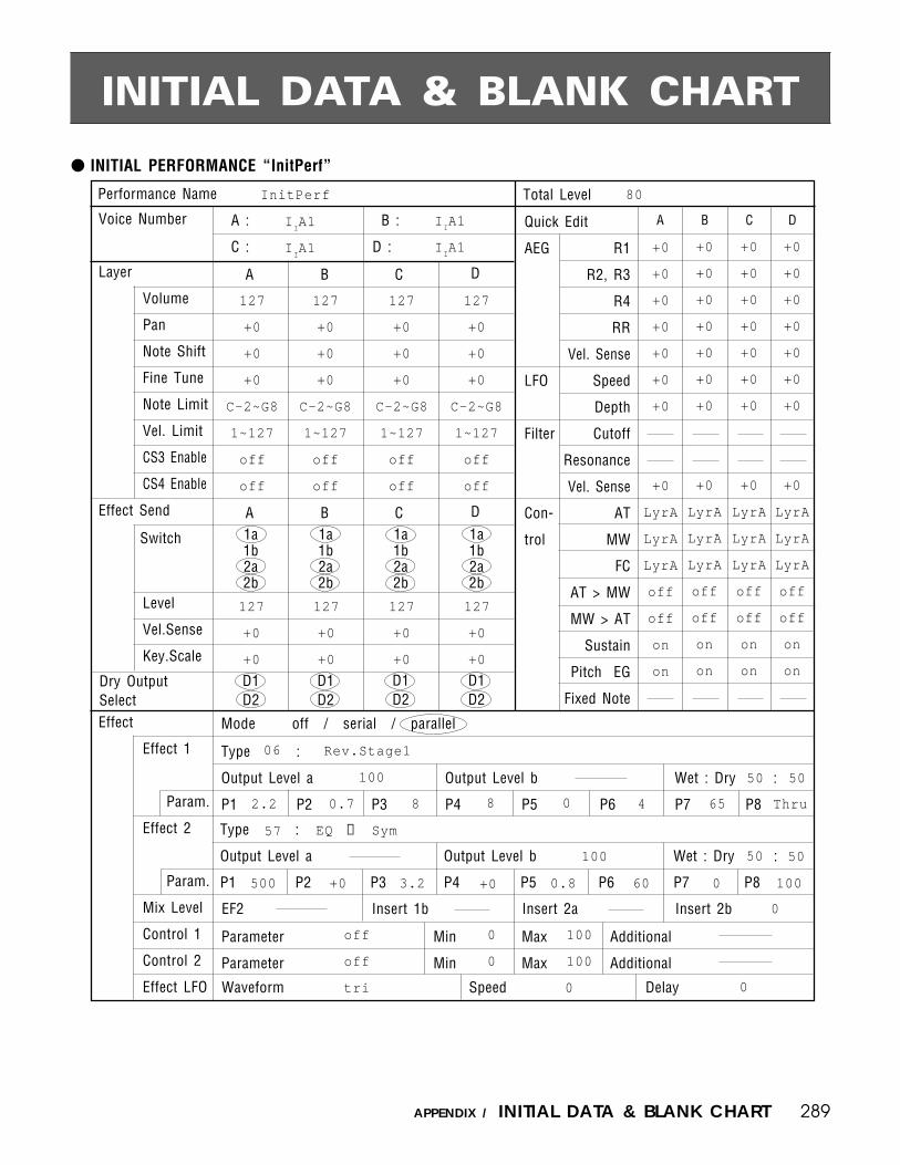
289APPENDIX / INITIAL DATA & BLANK CHART
A :
C :
B :
D :
Quick Edit
AEG R1
R2, R3
R4
RR
Vel. Sense
LFO Speed
Depth
Filter Cutoff
Resonance
Vel. Sense
Con- AT
trol MW
FC
AT > MW
MW > AT
Sustain
Pitch EG
Fixed Note
A
A
B
B
C
C
Switch 1a1b2a2b
1a1b2a2b
1a1b2a2b
D1D2
D1D2
D1D2
D1D2
C DA B
Mode off / serial / parallel
EF2 Insert 1b Insert 2a Insert 2b
Parameter Min Max Additional
Parameter Min Max Additional
Waveform Speed Delay
Total LevelPerformance Name
Type :
Output Level a Output Level b Wet : Dry :
P1 P2 P3 P4 P5 P6 P7 P8
Type :
Output Level a Output Level b Wet : Dry :
P1 P2 P3 P4 P5 P6 P7 P8
InitPerf 80
127
+0
+0
+0
C-2~G8
1~127
off
off
127
+0
+0
+0
+0
+0
+0
+0
+0
+0
+0
LyrA
LyrA
LyrA
off
off
on
on
06 Rev.Stage1
100 50 50
2.2 0.7 8 8 0 4 65 Thru
57 EQ → Sym
100 50 50
500 +0 3.2 +0 0.8 60
1a1b2a2b
Voice Number
Layer
Volume
Pan
Note Shift
Fine Tune
Note Limit
Vel. Limit
CS3 Enable
CS4 Enable
Effect Send
Level
Vel.Sense
Key.Scale
Effect
Effect 1
Param.
Effect 2
Param.
Mix Level
Control 1
Control 2
Effect LFO
Dry OutputSelect
INITIAL PERFORMANCE “InitPerf”
INITIAL DATA & BLANK CHART
IIA1
IIA1
IIA1
IIA1
127
+0
+0
+0
C-2~G8
1~127
off
off
127
+0
+0
127
+0
+0
+0
C-2~G8
1~127
off
off
127
+0
+0
127
+0
+0
+0
C-2~G8
1~127
off
off
127
+0
+0
D
D
+0
+0
+0
+0
+0
+0
+0
+0
LyrA
LyrA
LyrA
off
off
on
on
+0
+0
+0
+0
+0
+0
+0
+0
LyrA
LyrA
LyrA
off
off
on
on
+0
+0
+0
+0
+0
+0
+0
+0
LyrA
LyrA
LyrA
off
off
on
on
0 100
0
off
off
tri
0
0
100
100
0 0

290 APPENDIX / INITIAL DATA & BLANK CHART
INITIAL NORMAL VOICE “InitVce”
Mode normal / fixed Phase Delay
Random Vel.
Key Scale
Pmod Amod Fmod
Oscillator
Waveform
Fine Tune
Fixed Note
Random
Reverse
Amplitude EG
Scaling
Note
Offset
Filter
EG
Scaling
Note
Offset
Pitch
EG
Controller
MW
FC
AT
CS3(#=18)
CS4(#=19)
Mode atk / hold
R1 / HT
L3
R3
BP4BP1
L2
R2
BP3BP2
LFO
Waveform
Speed
Depth
SpeedSens
RRR4
Sensitivity Velocity
Atk Rate Vel
Rate Scaling
Sensitivity Type
Velocity
Attack Rate Vel
L0
RS
BP1
L1
R1
BP2
Type
L3
R3
BP4
Band
L4
R4
Reso
RL1
RR1
CTRL
RL2
RR2
L1
R2
BP3
Cutoff freq
Range
L1
R1
Velocity
L2
R2
L3
R3
L0
RS
Rate Velocity
RL1
RR
PB Range
Amod
Amod
Amod
Pmod
Pmod
Pmod
Volume Low Limit
Fmod
Fmod
Fmod
EG Bias
EG Bias
EG Bias
Cutoff
Cutoff
Cutoff
Sustain SW
Pitch Bias
Parameter
Parameter
Min
Min
Max
Max
Voice Name Total LevelInitVce 127
P244 Sin
+0
+0
0
off
0° 0
tri
64
0 0 0
0 +0
+0
63
C1
+0
G2
+0
63
63
E4
+0
63
63
C6
+0
0 50
+0
+0
+0
+0
+0
C1
+0
+0
+0
G2
+0
+0
+0
E4
+0
THRU
+0
+0
C6
+0
+0
+0
+0
+0
LFO
+0
+0
EGshift
+0
+0
1 oct
+0
63
+0
63
+0
63
+0
63
+0
63
+0
2
0
0
0
0
0
0
0
0
0
0
+0
+0
+0
+0
+0
+0
enable
0
0
100
100
Loop on / off
+0
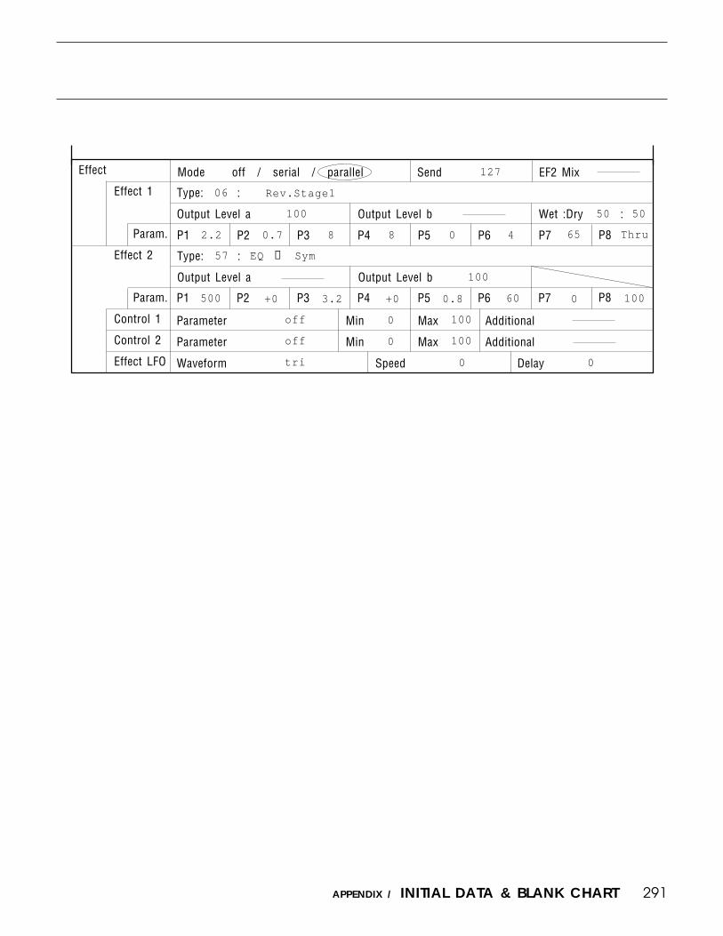
291APPENDIX / INITIAL DATA & BLANK CHART
Mode off / serial / parallelEffect
Effect 1
Param.
Effect 2
Param.
Control 1
Control 2
Effect LFO
Type: :
Output Level a Output Level b Wet :Dry :
P1 P2 P3 P4 P5 P6 P7 P8
P1 P2 P3 P4 P5 P6 P8P7
Parameter Min Max Additional
Parameter Min Max Additional
Waveform Speed Delay
Send EF2 Mix
Type: :
Output Level a Output Level b
127
06 Rev.Stage1
100 50 50
2.2 0.7 8 8 0 4 65 Thru
100
500 +0 3.2 +0 0.8 60 0 100
off
off
tri
0
0
100
100
0 0
EQ → Sym57

292 APPENDIX / INITIAL DATA & BLANK CHART
INITIAL DRUM VOICE “DR PTN”
Voice Name Total Level Vol Lo Limit
Effect SendKey Parameters
Waveform Vol. Nsft Tune Pan AltGNote
C1
C#1
D1
D#1
E1
F1
F#1
G1
G#1
A1
A#1
B1
C2
C#2
D2
D#2
E2
F2
F#2
G2
G#2
A2
A#2
B2
C3
C#3
D3
D#3
E3
Gate Rvs EF1
a b
a b
a b
a b
a b
a b
a b
a b
a b
a b
a b
a b
a b
a b
a b
a b
a b
a b
a b
a b
a b
a b
a b
a b
a b
a b
a b
a b
a b
Lvel VelS DryOut
1 2
1 2
1 2
1 2
1 2
1 2
1 2
1 2
1 2
1 2
1 2
1 2
1 2
1 2
1 2
1 2
1 2
1 2
1 2
1 2
1 2
1 2
1 2
1 2
1 2
1 2
1 2
1 2
1 2
DR PTN 127 0
P156 BD6
P155 BD5
P154 BD4
P153 BD3
P170 Tom2
P170 Tom2
P170 Tom2
P170 Tom2
P152 BD2
P151 BD1
P162 SD4
P169 Tom1
P169 Tom1
P160 SD2
P169 Tom1
P168 SDside
P161 SD3
P169 Tom1
P193 Clap
P196 Cowbell
P188 Cabasa
P173 HH light
P174 HH mid
P171 HH Open
P176 Crash
P176 Crash
P177 Ride
P178 RideBell
P189 CongaLo
120
120
121
127
103
105
112
119
115
119
119
127
127
127
127
127
127
127
127
127
127
127
127
127
127
127
127
127
97
EF2
a b
a b
a b
a b
a b
a b
a b
a b
a b
a b
a b
a b
a b
a b
a b
a b
a b
a b
a b
a b
a b
a b
a b
a b
a b
a b
a b
a b
a b
off
off
off
off
off
off
off
off
off
off
off
off
off
off
off
off
off
off
off
off
off
1
1
1
off
off
off
off
off
norm
norm
norm
norm
long
long
norm
norm
norm
norm
norm
verylong
long
norm
long
norm
long
long
short
short
short
short
norm
long
verylong
verylong
verylong
verylong
norm
off
off
off
off
off
off
off
off
off
off
off
off
off
off
off
off
off
off
off
off
off
off
off
off
off
off
off
off
off
+0
+0
+0
+0
+0
+0
+0
+0
+0
+0
+0
+0
+0
+2
+0
+3
+3
+0
+0
+0
+0
+0
+0
+0
+0
+0
+0
+0
+0
+0
+0
+0
+0
-6
-1
+3
+8
-3
-5
+0
-4
+0
-1
+6
+0
-2
+12
+0
+0
-5
+0
+0
+0
+0
+3
+0
+0
+2
+0
+0
+0
+0
+0
+0
+0
+0
+0
+0
+0
+0
+0
-21
+0
+0
+0
+0
+0
+0
+0
+0
+0
+0
+0
+1
+0
+0
+0
+0
+0
+0
+0
-24
-8
+8
+21
+0
+0
+0
-29
-10
+0
+9
+0
+0
+20
+8
+13
-26
+12
+12
+12
-11
-5
+8
+17
-17
127
127
127
127
97
90
95
98
127
127
109
94
98
123
89
124
113
92
99
104
90
111
94
87
102
109
107
107
100

293APPENDIX / INITIAL DATA & BLANK CHART
Type: :
Output Level a Output Level b Wet : Dry :
Waveform Vol. Nsft Tune Pan AltGNote
F3
F#3
G3
G#3
A3
A#3
B3
C4
C#4
D4
D#4
E4
F4
F#4
G4
G#4
A4
A#4
B4
C5
Gate EF1
a b
a b
a b
a b
a b
a b
a b
a b
a b
a b
a b
a b
a b
a b
a b
a b
a b
a b
a b
a b
Mode off / serial / parallelEffect
Effect 1
Param.
Effect 2
Param.
Mix Level
Control 1
Control 2
Effect LFO
P1 P2 P3 P4 P5 P6 P7 P8
P1 P2 P3 P4 P6
Type: :
Output Level a Output Level b Wet : Dry :
P5
Waveform Speed Delay
Parameter Min Max Additional
Parameter Min Max Additional
EF2 Insert 1b Insert 2a Insert 2b
Effect SendKey Parameters
P190 CongaMt
P191 CongaSlp
P187 Bongo
P187 Bongo
P201 Timbale
P201 Timbale
P198 Tmbrine
P194 Clave
P200 Temp1B1K
P186 AgogoHi
P186 AgogoHi
P204 Whistle
P157 BD7
P195 AnaCwbl
P158 BD8
P181 HHclAnlg
P166 SD8
P180 HHopAnlg
P167 SD9
P116 SynBs6
116
117
127
127
100
108
127
127
127
98
102
127
104
127
104
127
127
127
127
127
EF2
a b
a b
a b
a b
a b
a b
a b
a b
a b
a b
a b
a b
a b
a b
a b
a b
a b
a b
a b
a b
+0
+0
+0
+3
-4
-1
+0
+0
+0
-3
+2
-2
-3
+0
-4
+3
-2
+0
-6
-12
+0
+0
+0
+0
+0
+0
+0
+0
+0
+0
+0
+0
+0
+0
+0
+37
-23
+0
+0
+0
+8
+19
-15
+15
-2
+22
-12
-25
+30
-21
-7
+13
+0
-24
+0
+0
+0
+0
+0
+0
off
off
off
off
off
off
off
off
off
off
off
off
off
off
off
1
off
1
off
off
norm
norm
short
norm
norm
norm
norm
short
short
long
long
norm
long
norm
long
norm
norm
short
norm
short
off
off
off
off
off
off
off
off
off
off
off
off
off
off
off
off
off
off
off
off
100
100
98
99
99
99
101
108
127
102
104
97
127
127
127
113
127
111
127
127
+0
+0
+0
+0
+0
+0
+0
+0
+0
+0
+0
+0
+0
+0
+0
+0
+0
+0
+0
+0
50
100 0
2.0 +12 500 +12 1.4 0.9 86 36
100
500 +12 smll 10 0
100 100
Ef1 prm8
Ef2 prm8
0
0
98
42
tri 0 0
100
0
2.0
100
Rvs Lvel VelS DryOut
1 2
1 2
1 2
1 2
1 2
1 2
1 2
1 2
1 2
1 2
1 2
1 2
1 2
1 2
1 2
1 2
1 2
1 2
1 2
1 2
9P8P7+12
52 EQ→ER
EQ→Rev1
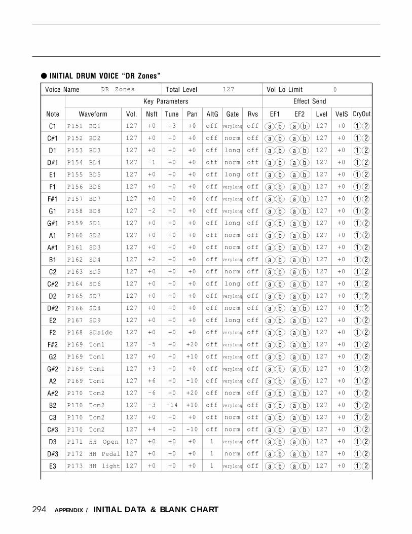
294 APPENDIX / INITIAL DATA & BLANK CHART
INITIAL DRUM VOICE “DR Zones”
Voice Name Total Level Vol Lo Limit
Effect SendKey Parameters
Waveform Vol. Nsft Tune Pan AltGNote
C1
C#1
D1
D#1
E1
F1
F#1
G1
G#1
A1
A#1
B1
C2
C#2
D2
D#2
E2
F2
F#2
G2
G#2
A2
A#2
B2
C3
C#3
D3
D#3
E3
Gate Rvs EF1
a b
a b
a b
a b
a b
a b
a b
a b
a b
a b
a b
a b
a b
a b
a b
a b
a b
a b
a b
a b
a b
a b
a b
a b
a b
a b
a b
a b
a b
Lvel VelS DryOut
1 2
1 2
1 2
1 2
1 2
1 2
1 2
1 2
1 2
1 2
1 2
1 2
1 2
1 2
1 2
1 2
1 2
1 2
1 2
1 2
1 2
1 2
1 2
1 2
1 2
1 2
1 2
1 2
1 2
DR Zones 127 0
P151 BD1
P152 BD2
P153 BD3
P154 BD4
P155 BD5
P156 BD6
P157 BD7
P158 BD8
P159 SD1
P160 SD2
P161 SD3
P162 SD4
P163 SD5
P164 SD6
P165 SD7
P166 SD8
P167 SD9
P168 SDside
P169 Tom1
P169 Tom1
P169 Tom1
P169 Tom1
P170 Tom2
P170 Tom2
P170 Tom2
P170 Tom2
P171 HH Open
P172 HH Pedal
P173 HH light
EF2
a b
a b
a b
a b
a b
a b
a b
a b
a b
a b
a b
a b
a b
a b
a b
a b
a b
a b
a b
a b
a b
a b
a b
a b
a b
a b
a b
a b
a b
+0
+0
+0
-1
+0
+0
+0
-2
+0
+0
+0
+2
+0
+0
+0
+0
+0
+0
-5
+0
+3
+6
-6
-3
+0
+4
+0
+0
+0
+3
+0
+0
+0
+0
+0
+0
+0
+0
+0
+0
+0
+0
+0
+0
+0
+0
+0
+0
+0
+0
+0
+0
-14
+0
+0
+0
+0
+0
+0
+0
+0
+0
+0
+0
+0
+0
+0
+0
+0
+0
+0
+0
+0
+0
+0
+0
+20
+10
+0
-10
+20
+10
+0
-10
+0
+0
+0
off
off
off
off
off
off
off
off
off
off
off
off
off
off
off
off
off
off
off
off
off
off
off
off
off
off
1
1
1
verylong
norm
long
norm
long
verylong
verylong
verylong
long
norm
norm
verylong
norm
long
verylong
norm
long
verylong
verylong
verylong
verylong
verylong
norm
verylong
norm
norm
verylong
norm
verylong
off
off
off
off
off
off
off
off
off
off
off
off
off
off
off
off
off
off
off
off
off
off
off
off
off
off
off
off
off
127
127
127
127
127
127
127
127
127
127
127
127
127
127
127
127
127
127
127
127
127
127
127
127
127
127
127
127
127
+0
+0
+0
+0
+0
+0
+0
+0
+0
+0
+0
+0
+0
+0
+0
+0
+0
+0
+0
+0
+0
+0
+0
+0
+0
+0
+0
+0
+0
127
127
127
127
127
127
127
127
127
127
127
127
127
127
127
127
127
127
127
127
127
127
127
127
127
127
127
127
127

295APPENDIX / INITIAL DATA & BLANK CHART
Waveform Vol. Nsft Tune Pan AltGNote
F3
F#3
G3
G#3
A3
A#3
B3
C4
C#4
D4
D#4
E4
F4
F#4
G4
G#4
A4
A#4
B4
C5
Gate Rvs EF1
a b
a b
a b
a b
a b
a b
a b
a b
a b
a b
a b
a b
a b
a b
a b
a b
a b
a b
a b
a b
Lvel VelS DryOut
1 2
1 2
1 2
1 2
1 2
1 2
1 2
1 2
1 2
1 2
1 2
1 2
1 2
1 2
1 2
1 2
1 2
1 2
1 2
1 2
Mode off / serial / parallelEffect
Effect 1
Param.
Effect 2
Param.
Mix Level
Control 1
Control 2
Effect LFO
Type: :
Output Level a Output Level b Wet : Dry :
P1 P2 P3 P4 P5 P6 P7 P8
P1 P2 P3 P4 P6 P8
Type: :
Output Level a Output Level b Wet : Dry :
P7P5
Waveform Speed Delay
Parameter Min Max Additional
Parameter Min Max Additional
EF2 Insert 1b Insert 2a Insert 2b
Effect SendKey Parameters
P174 HH mid
P175 HH heavy
P180 HHopAnlg
P181 HHclAnlg
P176 Crash
P177 Ride
P178 RideBell
P179 AnlgTom
P179 AnlgTom
P179 AnlgTom
P179 AnlgTom
P179 AnlgTom
P192 AnaConga
P192 AnaConga
P193 Clap
P195 AnaCwbl
P194 Clave
P183 RezClick
P198 Tmbrine
P122 SynBs9
EF2
a b
a b
a b
a b
a b
a b
a b
a b
a b
a b
a b
a b
a b
a b
a b
a b
a b
a b
a b
a b
+0
+0
+0
+0
+0
+0
+0
-7
-5
-1
+1
+4
+0
-3
+0
+0
-3
+0
+0
-24
+0
+0
+0
+0
+0
+0
+0
+0
+0
+0
+0
+0
+0
+0
+0
+0
+0
+0
+0
+0
+0
+0
+0
+0
+0
+0
+0
-20
-10
+0
+10
+20
-10
+10
+0
+0
+0
-15
+0
+0
1
1
2
2
off
off
off
off
off
off
off
off
off
off
off
off
5
off
off
off
verylong
verylong
verylong
verylong
verylong
verylong
verylong
short
short
short
short
short
norm
verylong
verylong
verylong
verylong
verylong
verylong
short
off
off
off
off
off
off
off
off
off
off
off
off
off
off
off
off
off
off
off
off
+0
+0
+0
+0
+0
+0
+0
+0
+0
+0
+0
+0
+0
+0
+0
+0
+0
+0
+0
+0
47
100% 70 30
25 2.5 +8 +2 500 250 +30 0
100% 40
200 +12 800 +6 1.3 0.8 13 18
100 100
Out2 wet
EF1 prm8
0
0
100
35
tri 0 0
60
50 EQ → Rev1
Dist → Dly
127
127
127
127
127
127
127
127
127
127
127
127
127
127
127
127
127
127
127
127
127
127
127
127
127
127
127
127
127
127
127
127
127
127
127
127
127
127
127
127

296 APPENDIX / INITIAL DATA & BLANK CHART
INITIAL DRUM VOICE “DR GMIDI”
Voice Name Total Level Vol Lo Limit
Effect SendKey Parameters
Waveform Vol. Nsft Tune Pan AltGNote
C1
C#1
D1
D#1
E1
F1
F#1
G1
G#1
A1
A#1
B1
C2
C#2
D2
D#2
E2
F2
F#2
G2
G#2
A2
A#2
B2
C3
C#3
D3
D#3
E3
Gate Rvs EF1
a b
a b
a b
a b
a b
a b
a b
a b
a b
a b
a b
a b
a b
a b
a b
a b
a b
a b
a b
a b
a b
a b
a b
a b
a b
a b
a b
a b
a b
Lvel VelS DryOut
1 2
1 2
1 2
1 2
1 2
1 2
1 2
1 2
1 2
1 2
1 2
1 2
1 2
1 2
1 2
1 2
1 2
1 2
1 2
1 2
1 2
1 2
1 2
1 2
1 2
1 2
1 2
1 2
1 2
DR GMIDI 127 0
P151 BD1
P168 SDside
P160 SD2
P193 Clap
P166 SD8
P169 Tom1
P174 HH mid
P169 Tom1
P172 HH Pedal
P169 Tom1
P171 HH Open
P169 Tom1
P169 Tom1
P176 Crash
P169 Tom1
P177 Ride
P176 Crash
P178 RideBell
P198 Tmbrine
P176 Crash
P196 Cowbell
P176 Crash
P191 CongaSlp
P177 Ride
P187 Bongo
P187 Bongo
P190 CongaMt
P189 CongaLo
P189 CongaLo
127
127
127
127
127
127
127
127
127
127
127
127
127
127
127
127
127
127
127
127
127
127
127
127
127
127
127
127
127
EF2
a b
a b
a b
a b
a b
a b
a b
a b
a b
a b
a b
a b
a b
a b
a b
a b
a b
a b
a b
a b
a b
a b
a b
a b
a b
a b
a b
a b
a b
+0
+2
+0
+1
+1
-8
+1
-6
+0
-3
+2
+2
+7
+0
+12
+0
-4
+0
-2
-8
+0
+0
+0
-2
+3
-2
+0
+5
+0
+3
+0
+0
+0
+0
+0
+0
+0
+0
+0
+0
+0
+0
+0
+0
+0
+0
+0
+0
+0
+0
+0
+0
-14
+0
-2
-14
+0
+0
+0
+0
+0
+0
+0
-18
+0
-16
+0
-12
+0
-6
+3
-10
+10
+0
+15
+0
+0
+15
+15
+0
+0
+0
+0
+0
+0
+0
+0
off
off
off
off
off
off
1
off
1
off
1
off
off
off
off
off
off
off
off
off
off
off
off
off
off
off
off
off
off
verylong
norm
long
norm
long
verylong
long
verylong
long
verylong
verylong
verylong
norm
verylong
verylong
verylong
verylong
verylong
long
verylong
norm
verylong
norm
verylong
norm
norm
norm
norm
norm
off
off
off
off
off
off
off
off
off
off
off
off
off
off
off
off
off
off
off
off
off
on
off
off
off
off
off
off
off
127
127
127
127
127
127
127
127
127
127
127
127
127
127
127
127
127
127
127
127
127
127
127
127
127
127
127
127
127
+0
+0
+0
+0
+0
+0
+0
+0
+0
+0
+0
+0
+0
+0
+0
+0
+0
+0
+0
+0
+0
+0
+0
+0
+0
+0
+0
+0
+0

297APPENDIX / INITIAL DATA & BLANK CHART
P6 30 25 2.5
+30 0
Waveform Vol. Nsft Tune Pan AltGNote
F3
F#3
G3
G#3
A3
A#3
B3
C4
C#4
D4
D#4
E4
F4
F#4
G4
G#4
A4
A#4
B4
C5
Gate Rvs EF1
a b
a b
a b
a b
a b
a b
a b
a b
a b
a b
a b
a b
a b
a b
a b
a b
a b
a b
a b
a b
Lvel VelS DryOut
1 2
1 2
1 2
1 2
1 2
1 2
1 2
1 2
1 2
1 2
1 2
1 2
1 2
1 2
1 2
1 2
1 2
1 2
1 2
1 2
Mode off / serial / parallelEffect
Effect 1
Param.
Effect 2
Param.
Mix Level
Control 1
Control 2
Effect LFO
Type: :
Output Level a Output Level b Wet : Dry :
P1 P2 P3 P4 P5
P1 P2 P3 P4 P6 P8
Type: :
Output Level a Output Level b Wet : Dry :
P7P5
Waveform Speed Delay
Parameter Min Max Additional
Parameter Min Max Additional
EF2 Insert 1b Insert 2a Insert 2b
Effect SendKey Parameters
P201 Timbale
P201 Timbale
P186
AgogoHi
P186
AgogoHi
P188 Cabaso
P197 Maracas
P204 Whistle
P204 Whistle
P195 AnaCwbl
P179 AnlgTom
P194 Clave
P192 AnaConga
P194 Clave
P184 VcDrmBD
P185 VcDrmSD
P203 Triangle
P203 Triangle
P183 RezClick
P183
RezClick
P218
OrchHit2
127
127
127
127
127
127
127
127
127
127
127
127
127
127
127
127
EF2
a b
a b
a b
a b
a b
a b
a b
a b
a b
a b
a b
a b
a b
a b
a b
a b
a b
a b
a b
a b
127
127
127
127
+0
-5
+0
-5
+0
+0
-2
-4
+0
+0
-4
+0
-10
+0
+0
+0
+0
+0
4
+0
+0
+0
+0
+0
+0
+0
+0
+0
+0
+0
+0
+0
+0
+0
+0
+0
+0
+0
+0
+0
+0
+0
+25
+19
-20
-18
+0
+0
+0
+0
+0
+0
+25
+0
+0
+0
+0
-15
+15
+0
off
off
off
off
off
off
off
off
off
off
off
off
off
off
off
5
5
off
off
off
verylong
verylong
verylong
verylong
norm
long
norm
long
norm
long
verylong
verylong
verylong
verylong
verylong
short
verylong
verylong
verylong
norm
off
off
off
off
off
off
off
off
off
off
off
off
off
off
off
off
off
off
off
off
127
127
127
127
127
127
127
127
127
127
127
127
127
127
127
127
127
127
127
127
+0
+0
+0
+0
+0
+0
+0
+0
+0
+0
+0
+0
+0
+0
+0
+0
+0
+0 +0 Dist
→ Dly 100% 70
+2
500 250
50 EQ → Rev1 100% 36 64 200
+12 800 +6 1.3
0.8
13
18 100 100
Out2 wet
EF1 prm8 0 0
100
35
+0
47
+8
P8P7

298 APPENDIX / INITIAL DATA & BLANK CHART
INITIAL DRUM VOICE “DR Efect”
Voice Name Total Level Vol Lo Limit
Effect Send
Waveform Vol. Nsft Tune Pan AltGNote
C1
C#1
D1
D#1
E1
F1
F#1
G1
G#1
A1
A#1
B1
C2
C#2
D2
D#2
E2
F2
F#2
G2
G#2
A2
A#2
B2
C3
C#3
D3
D#3
E3
Gate Rvs EF1
a b
a b
a b
a b
a b
a b
a b
a b
a b
a b
a b
a b
a b
a b
a b
a b
a b
a b
a b
a b
a b
a b
a b
a b
a b
a b
a b
a b
a b
Lvel VelS DryOut
1 2
1 2
1 2
1 2
1 2
1 2
1 2
1 2
1 2
1 2
1 2
1 2
1 2
1 2
1 2
1 2
1 2
1 2
1 2
1 2
1 2
1 2
1 2
1 2
1 2
1 2
1 2
1 2
1 2
DR Efect 127 0
P145 Marimba
P152 BD2
P150 Xylophon
P159 SD1
P160 SD2
P161 SD3
P162 SD4
P163 SD5
P169 Tom1
P169 Tom1
P169 Tom1
P018 PrcOrgl
P170 Tom2
P170 Tom2
P170 Tom2
P164 SD6
P172 HH Pedal
P171 HH Open
P178 RideBell
P177 Ride
P176 Crash
P176 Crash
P176 Crash
P168 SDside
P203 Triangle
P203 Triangle
P199 Timpani
P196 Cowbell
P196 Cowbell
127
127
127
127
127
127
127
127
127
127
127
127
127
127
127
127
127
127
127
127
127
127
127
127
127
127
127
127
127
EF2
a b
a b
a b
a b
a b
a b
a b
a b
a b
a b
a b
a b
a b
a b
a b
a b
a b
a b
a b
a b
a b
a b
a b
a b
a b
a b
a b
a b
a b
Key Parameters
-20
-9
-1
-9
-10
-6
+2
-2
-6
+0
-9
-20
-17
-5
+7
-8
-10
+26
+25
+5
+24
+31
+11
-14
+8
+21
+0
-25
-15
+0
+0
+0
+0
+14
-57
+0
+0
+0
+0
+0
+0
+0
+0
+0
+0
+0
+0
+0
+0
+0
+0
+0
+0
+0
-1
+0
-9
+0
+0
+0
+0
+0
+0
+0
+0
+0
+0
+0
+0
+0
+0
+0
+0
+0
+0
+0
+0
+0
+0
+0
+0
+0
+0
+0
+0
+0
+0
off
off
off
off
off
off
off
off
off
off
off
off
off
off
off
off
1
1
off
off
off
off
off
off
2
2
off
off
off
verylong
norm
norm
long
norm
norm
norm
norm
long
long
norm
verylong
verylong
verylong
norm
norm
verylong
long
verylong
short
verylong
verylong
verylong
norm
verylong
long
verylong
norm
norm
off
off
off
off
off
off
off
off
off
off
off
off
off
off
off
off
off
off
off
off
off
off
off
off
off
off
off
off
off
127
127
127
127
127
127
127
127
127
127
127
127
127
127
127
127
127
127
127
127
127
127
127
127
127
127
127
127
127
+5
+5
+5
+7
+5
+5
+5
+5
+5
+5
+5
+5
+7
+7
+7
+5
+5
+2
+5
+5
+5
+5
+5
+7
+7
+7
+3
+7
+7

299APPENDIX / INITIAL DATA & BLANK CHART
Waveform Vol. Nsft Tune Pan AltGNote
F3
F#3
G3
G#3
A3
A#3
B3
C4
C#4
D4
D#4
E4
F4
F#4
G4
G#4
A4
A#4
B4
C5
Gate Rvs EF1
a b
a b
a b
a b
a b
a b
a b
a b
a b
a b
a b
a b
a b
a b
a b
a b
a b
a b
a b
a b
Lvel VelS DryOut
1 2
1 2
1 2
1 2
1 2
1 2
1 2
1 2
1 2
1 2
1 2
1 2
1 2
1 2
1 2
1 2
1 2
1 2
1 2
1 2
Mode off / serial / parallelEffect
Effect 1
Param.
Effect 2
Param.
Mix Level
Control 1
Control 2
Effect LFO
Type: :
Output Level a Output Level b Wet : Dry :
P1 P2 P3 P4 P5 P6 P7 P8
P1 P2 P3 P4 P6 P8
Type: :
Output Level a Output Level b Wet : Dry :
P7P5
Waveform Speed Delay
Parameter Min Max Additional
Parameter Min Max Additional
EF2 Insert 1b Insert 2a Insert 2b
Effect SendKey Parameters
EF2
a b
a b
a b
a b
a b
a b
a b
a b
a b
a b
a b
a b
a b
a b
a b
a b
a b
a b
a b
a b
P197 Maracas
P189 CongaLo
P191 CongaSlp
P190 CongaMt
P213 Mellow
P216 Seq2
P201 Timbale
P206 E.P. Np
P136 DistWvLp
P200 Temp1BIK
P194 Clave
P186 AgogoHi
P184 VcDrmBD
P217 OrchHit1
P178 RideBell
P185 VcDrmSD
P094 Kalimba
P207 Bamboo
P205 Bottle
P208 Temp Ra
127
127
127
127
127
127
127
127
127
127
127
127
127
127
127
127
110
127
127
93
-11
-16
-13
+7
-34
-32
+6
+12
-15
-48
-47
-19
+0
+36
-14
-6
-8
-17
-31
-3
+0
+0
+0
+0
-20
-20
+0
+0
+0
+15
-41
-26
+0
+0
+0
+0
+0
+19
+20
+0
+0
+0
+0
+0
+0
+0
+0
+0
+0
+0
+0
+0
+0
+0
+0
+0
+0
+0
+0
+0
off
off
off
off
off
off
off
off
off
off
off
off
off
off
off
off
off
off
off
off
short
verylong
long
norm
norm
verylong
norm
norm
verylong
norm
norm
verylong
verylong
verylong
verylong
verylong
long
norm
long
verylong
off
off
off
off
off
off
off
off
off
off
off
off
off
off
off
off
off
off
off
off
90
100
127
127
127
127
127
127
127
127
127
127
127
127
127
90
93
127
127
127
+7
+5
+5
+6
+3
+3
+3
+5
+5
+3
+5
+5
+5
+5
+5
+5
+5
+5
+5
+5
Dist & Rev
100% 100% 50 50
25 2.0 +6 +12 2.7 1.0 50 12.0
Pit & Rev
100% 100% 100 0
-7 +0 +5 +0 0.8 1.5 50 9.0
100 100
Out1 wet
EF1 prm5
0
0
100
50
tri 0 0
69
67
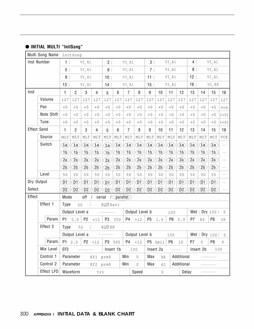
300 APPENDIX / INITIAL DATA & BLANK CHART
INITIAL MULTI “InitSong”
1 :
5 :
9 :
13 :
2 :
6 :
10 :
14 :
3 :
7 :
11 :
15 :
4 :
8 :
12 :
16 :
1
1
1a
1b
2a
2b
D1
D2
2
2
1a
1b
2a
2b
D1
D2
3
3
1a
1b
2a
2b
D1
D2
4
4
1a
1b
2a
2b
D1
D2
5
5
1a
1b
2a
2b
D1
D2
6
6
1a
1b
2a
2b
D1
D2
8
8
1a
1b
2a
2b
D1
D2
9
9
1a
1b
2a
2b
D1
D2
10
10
1a
1b
2a
2b
D1
D2
11
11
1a
1b
2a
2b
D1
D2
12
12
1a
1b
2a
2b
D1
D2
13
13
1a
1b
2a
2b
D1
D2
14
14
1a
1b
2a
2b
D1
D2
15
15
1a
1b
2a
2b
D1
D2
7
7
1a
1b
2a
2b
D1
D2
Mode off / serial / parallel
Type :
Output Level a Output Level b Wet : Dry :
P1 P2 P3 P4 P5 P6 P7 P8
Multi Song Name
Parameter Min Max Additional
Parameter Min Max Additional
EF2 Insert 1b Insert 2a Insert 2b
Waveform Speed Delay
Type :
Output Level a Output Level b Wet : Dry :
P1 P2 P3 P4 P5 P6 P7 P8
InitSong
127
+0
+0
+0
127
vce
(+0)
(+0)
VCE
100 0
2.0 +12 500 +12 1.4 0.9 86 36
52
100 0
2.0 Smll 10 9
100 100
Ef1 prm8
Ef2 prm8
tri
0
0
98
42
0
50
+12 500 +12 0
100
EQ→Rev1
VIIA1
VIIA1
VIIA1
VIIA1
VIIA1
VIIA1
VIIA1
VIIA1
VIIA1
VIIA1
VIIA1
VIIA1
VIIA1
VIIA1
VIIA1
VIIH8
127
+0
+0
+0
MLT
50
127
+0
+0
+0
MLT
50
127
+0
+0
+0
MLT
50
127
+0
+0
+0
MLT
50
127
+0
+0
+0
MLT
50
127
+0
+0
+0
MLT
50
127
+0
+0
+0
MLT
50
127
+0
+0
+0
MLT
50
127
+0
+0
+0
MLT
50
127
+0
+0
+0
MLT
50
127
+0
+0
+0
MLT
50
127
+0
+0
+0
MLT
50
127
+0
+0
+0
MLT
50
127
+0
+0
+0
MLT
50
MLT
50
16
16
Inst Number
Inst
Volume
Pan
Note Shift
Tune
Effect Send
Source
Switch
Level
Dry Output
Select
Effect
Effect 1
Param.
Effect 2
Param.
Mix Level
Control 1
Control 2
Effect LFO
100
EQ→ER

301APPENDIX / INITIAL DATA & BLANK CHART
SYSTEM SETUP
A2
C2
E2
G2
A3
C3
E3
G3
A4
C4
E4
G4
A5
C5
E5
G5
A6
C6
E6
G6
A8
C8
E8
G8
B1
D1
F1
H1
B3
D3
F3
H3
B4
D4
F4
H4
B5
D5
F5
H5
B6
D6
F6
H6
B7
D7
F7
H7
A7
C7
E7
G7
Note shift Tune Ctrl Reset Local
T.Ch R.Ch Device No. Volume Ctrl Bulk Protect
Curve Fix
Click Beat Clock MIDI Control
AT R.Ch Accent 1 Accent 2 Accent 3 Fix
Loop Chain
off / normal / direct / table
B2
D2
F2
H2
B8
D8
F8
H8
A1
C1
E1
G1
Synth
MIDI
Velocity
Sequencer
Recording
Song
Program Change
Source
Bank(MSB)
Bank(LSB)
Program
Source
Bank(MSB)
Bank(LSB)
Program
Source
Bank(MSB)
Bank(LSB)
Program
Source
Bank(MSB)
Bank(LSB)
Program
+0 +0 off on
01 007 on
0 off
on
off
1/4
kbd
int
56
off off
on
88 120 kbd
omni all
000
064
000
000
064
000
000
064
000
000
064
000
000
064
000
000
064
000
000
064
000
000
064
000
000
064
000
000
064
000
000
064
000
000
064
000
000
064
000
000
064
000
000
064
000
000
064
000
000
064
000
000
064
000
000
064
000
000
064
000
000
064
000
000
064
000
000
064
000
000
064
000
000
064
000
000
064
000
000
064
000
000
064
000
000
064
000
000
064
000
000
064
000
000
064
000
000
064
000
000
064
000
000
064
000
000
064
000
000
064
000
000
064
000
000
064
000
000
064
000
000
064
000
000
064
000
000
064
000
000
064
000
000
064
000
000
064
000
000
064
000
000
064
000
000
064
000
000
064
000
000
064
000
000
064
000
000
064
000
000
064
000
000
064
000
000
064
000
000
064
000
000
064
000
000
064
000
000
064
000
000
064
000
000
064
000
000
064
000
000
064
000

302 APPENDIX / INITIAL DATA & BLANK CHART
INITIAL PERFORMANCE LIST (1)

303APPENDIX / INITIAL DATA & BLANK CHART

304 APPENDIX / INITIAL DATA & BLANK CHART
INITIAL PERFORMANCE LIST (2)

305APPENDIX / INITIAL DATA & BLANK CHART

306 APPENDIX / INITIAL DATA & BLANK CHART
INITIAL VOICE LIST (1)

307APPENDIX / INITIAL DATA & BLANK CHART
INITIAL VOICE LIST (2)

308 APPENDIX / INITIAL DATA & BLANK CHART
INITIAL VOICE LIST (3)

309APPENDIX / INITIAL DATA & BLANK CHART
INITIAL VOICE LIST (4)

310 APPENDIX / INITIAL DATA & BLANK CHART
WAVE LISTWave No. Group Wave Name
1 Piano Piano2 Keyboard HardEp3 HardEpLp4 SoftEp5 SoftEpLp6 SynthEp7 SynthEpLp8 Clavi 19 Clavi 1Lp
10 Clavi 211 Clavi 2Lp12 Harpsi13 HarpsiLp14 Acrdion15 AcrdionLp16 Organ 117 Organ 1Lp18 PrcOrg119 PrcOrg1Lp20 PrcOrg221 PrcOrg2Lp22 RockOrg23 Pipe Wv24 Pipe WvLp25 Brass Trumpet26 TrumpetLp27 MuteTp28 MuteTpLp29 Trombone30 TromBneLp31 Horn32 Tuba33 TpEns34 TpEnsLp35 BrsEns36 BrsEnsLp37 Wind Baritone38 BaritneLp39 Tenor40 TenorLp41 AltoSax42 AltoSaxLp43 Soprano44 SopranoLp45 Clarinet46 Bassoon47 Oboe48 EngHorn49 Piccolo50 Recorder51 Flute52 Panflute53 PnFluteLp54 Strings Strings155 Strngs1Lp56 Strings257 Violin58 Viola59 Pizz60 A.Guitar GtrSteel61 GtrStelLp
Wave No. Group Wave Name62 GtrNyln63 GtrNylnLp64 12String65 12StrngLp66 E.Guitar EgSngl167 EgSngl1Lp68 EgSngl269 EgSngl2Lp70 EgMute171 EgMute272 EgComp73 EgCompLp74 EgHarm175 EgHarm1Lp76 EgHarm277 EgHarm2Lp78 Bass WoodBass79 FingBs80 FingBsLp81 PickBs182 PickBs1Lp83 PickBs284 PickBs2Lp85 FretLess86 FretLs Lp87 ThumpBs88 ThumpBsLp89 SlapBs90 SlapBsLp91 Folk Dulcimer92 DulcimrD93 DlcmSplt94 Kalimba95 Sitar96 Harp97 Synth SynBrs198 SynBrs1Lp99 SynBrs2
100 SynBrs2Lp101 SynBrs3102 SynBrs3Lp103 SynBrs4104 SynBrs4Lp105 SynBrsWv106 SynBs1107 SynBs1Lp108 SynBs2109 SynBs2Lp110 SynBs3111 SynBs3Lp112 SynBs4113 SynBs4Lp114 SynBs5115 SynBs5Lp116 SynBs6117 SynBs6Lp118 SynBs7119 SynBs7Lp120 SynBs8121 SynBs8Lp122 SynBs9
Wave No. Group Wave Name123 SynBs9Lp124 SynBs10125 SynBs10Lp126 Pad 1127 Pad 1Lp128 Pad 2129 Pad 3130 Pad 4131 Pad 5132 SynLead1133 SynLead2134 SynStWv135 DistWv136 DistWvLp137 Choir ChoirAa138 ChoirAaLp139 ChoirOo140 ChoirOoLp141 Itopia142 Tuned Glocken143 Percussion HandBell144 HndBellLp145 Marimba146 SteelDrm147 Tubular148 TubularLp149 Vibes150 Xylophon151 Drum BD1152 BD2153 BD3154 BD4155 BD5156 BD6157 BD7158 BD8159 SD1160 SD2161 SD3162 SD4163 SD5164 SD6165 SD7166 SD8167 SD9168 SD side169 Tom1170 Tom2171 HH Open172 HH Pedal173 HH light174 HH mid175 HH heavy176 Crash177 Ride178 RideBell179 AnlgTom180 HHopAnlg181 HHclAnlg182 Scratch183 RezClick
Wave No. Group Wave Name184 VcDrmBD185 VcDrmSD186 Percussion AgogoHi187 Bongo188 Cabasa189 CongaLo190 CongaMt191 CongaSlp192 AnaConga193 Clap194 Clave195 AnaCwbl196 Cowbell197 Maracas198 Tmbrine199 Timpani200 TemplBlk201 Timbale202 Timbale2203 Triangle204 Whistle205 SE Bottle206 E.P. Np207 Bamboo208 Temp Ra209 Typist210 VoiceAtk211 ChouCho212 Vox Bell213 Mellow214 Bell Mix215 Seq1216 Seq2217 OrchHit1218 OrchHit2219 Noise220 Osc AnlgSaw1221 AnlgSaw2222 Pulse 10223 Pulse 25224 Pulse 50225 Digital1226 Digital2227 Digital3228 Digital4229 Digital5230 Digital6231 Digital7232 Digital8233 Digital9234 Digitl10235 Digitl11236 Digitl12237 DigiVox1238 DigiVox2239 DigiVox3240 DigiVox4241 DigiVox5242 DigiWild243 Tri244 Sin

311APPENDIX / INITIAL DATA & BLANK CHART
A :
C :
B :
D :
Quick Edit
AEG R1
R2, R3
R4
RR
Vel. Sense
LFO Speed
Depth
Filter Cutoff
Resonance
Vel. Sense
Con- AT
trol MW
FC
AT > MW
MW > AT
Sustain
Pitch EG
Fixed Note
A
A
B
B
C
C
Switch 1a1b2a2b
1a1b2a2b
1a1b2a2b
D1D2
D1D2
D1D2
D1D2
C DA B
Mode off / serial / parallel
EF2 Insert 1b Insert 2a Insert 2b
Parameter Min Max Additional
Parameter Min Max Additional
Waveform Speed Delay
Total LevelPerformance Name
Type :
Output Level a Output Level b Wet : Dry :
P1 P2 P3 P4 P5 P6 P7 P8
Type :
Output Level a Output Level b Wet : Dry :
P1 P2 P3 P4 P5 P6 P7 P8
1a1b2a2b
Voice Number
Layer
Volume
Pan
Note Shift
Fine Tune
Note Limit
Vel. Limit
CS3 Enable
CS4 Enable
Effect Send
Level
Vel.Sense
Key.Scale
Effect
Effect 1
Param.
Effect 2
Param.
Mix Level
Control 1
Control 2
Effect LFO
Dry OutputSelect
BLANK CHART — PERFORMANCE
D
D

312 APPENDIX / INITIAL DATA & BLANK CHART
BLANK CHART — VOICE
Mode normal / fixed Phase Delay
Random Vel.
Key Scale
Pmod Amod Fmod
Oscillator
Waveform
Fine Tune
Fixed Note
Random
Reverse
Amplitude EG
Scaling
Note
Offset
Filter
EG
Scaling
Note
Offset
Pitch
EG
Controller
MW
FC
AT
CS3(#=18)
CS4(#=19)
Mode atk / hold
R1 / HT
L3
R3
BP4BP1
L2
R2
BP3BP2
LFO
Waveform
Speed
Depth
SpeedSens
RRR4
Sensitivity Velocity
Atk Rate Vel
Rate Scaling
Sensitivity Type
Velocity
Attack Rate Vel
L0
RS
BP1
L1
R1
BP2
Type
L3
R3
BP4
Band
L4
R4
Reso
RL1
RR1
CTRL
RL2
RR2
L1
R2
BP3
Cutoff freq
Range
L1
R1
Velocity
L2
R2
L3
R3
L0
RS
Rate Velocity
RL1
RR
PB Range
Amod
Amod
Amod
Pmod
Pmod
Pmod
Volume Low Limit
Fmod
Fmod
Fmod
EG Bias
EG Bias
EG Bias
Cutoff
Cutoff
Cutoff
Sustain SW
Pitch Bias
Parameter
Parameter
Min
Min
Max
Max
Voice Name Total Level
Loop on / off
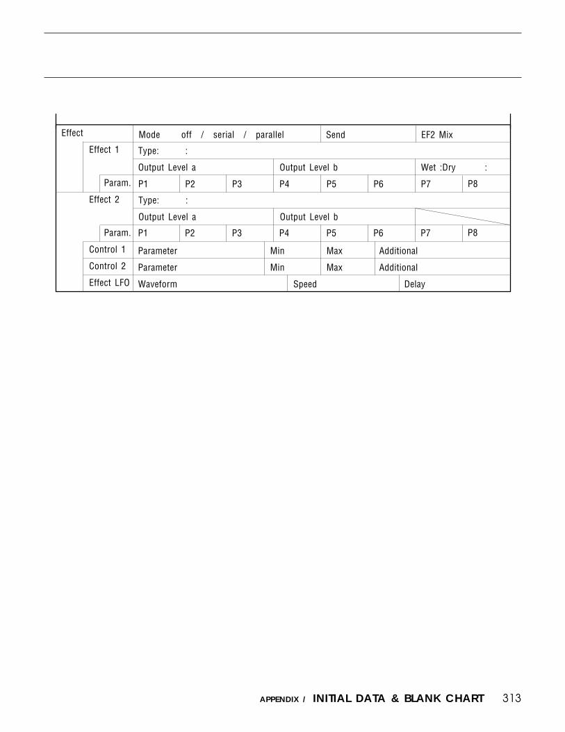
313APPENDIX / INITIAL DATA & BLANK CHART
Mode off / serial / parallelEffect
Effect 1
Param.
Effect 2
Param.
Control 1
Control 2
Effect LFO
Type: :
Output Level a Output Level b Wet :Dry :
P1 P2 P3 P4 P5 P6 P7 P8
P1 P2 P3 P4 P5 P6 P8P7
Parameter Min Max Additional
Parameter Min Max Additional
Waveform Speed Delay
Send EF2 Mix
Type: :
Output Level a Output Level b

314 APPENDIX / INITIAL DATA & BLANK CHART
BLANK CHART — DRUM VOICE
Voice Name Total Level Vol Lo Limit
Effect SendKey Parameters
Waveform Vol. Nsft Tune Pan AltGNote
C1
C#1
D1
D#1
E1
F1
F#1
G1
G#1
A1
A#1
B1
C2
C#2
D2
D#2
E2
F2
F#2
G2
G#2
A2
A#2
B2
C3
C#3
D3
D#3
E3
Gate Rvs EF1
a b
a b
a b
a b
a b
a b
a b
a b
a b
a b
a b
a b
a b
a b
a b
a b
a b
a b
a b
a b
a b
a b
a b
a b
a b
a b
a b
a b
a b
Lvel VelS DryOut
1 2
1 2
1 2
1 2
1 2
1 2
1 2
1 2
1 2
1 2
1 2
1 2
1 2
1 2
1 2
1 2
1 2
1 2
1 2
1 2
1 2
1 2
1 2
1 2
1 2
1 2
1 2
1 2
1 2
EF2
a b
a b
a b
a b
a b
a b
a b
a b
a b
a b
a b
a b
a b
a b
a b
a b
a b
a b
a b
a b
a b
a b
a b
a b
a b
a b
a b
a b
a b

315APPENDIX / INITIAL DATA & BLANK CHART
Type: :
Output Level a Output Level b Wet : Dry :
Waveform Vol. Nsft Tune Pan AltGNote
F3
F#3
G3
G#3
A3
A#3
B3
C4
C#4
D4
D#4
E4
F4
F#4
G4
G#4
A4
A#4
B4
C5
Gate EF1
a b
a b
a b
a b
a b
a b
a b
a b
a b
a b
a b
a b
a b
a b
a b
a b
a b
a b
a b
a b
Mode off / serial / parallelEffect
Effect 1
Param.
Effect 2
Param.
Mix Level
Control 1
Control 2
Effect LFO
P1 P2 P3 P4 P5 P6 P7 P8
P1 P2 P3 P4 P6
Type: :
Output Level a Output Level b Wet : Dry :
P5
Waveform Speed Delay
Parameter Min Max Additional
Parameter Min Max Additional
EF2 Insert 1b Insert 2a Insert 2b
Effect SendKey Parameters
EF2
a b
a b
a b
a b
a b
a b
a b
a b
a b
a b
a b
a b
a b
a b
a b
a b
a b
a b
a b
a b
Rvs Lvel VelS DryOut
1 2
1 2
1 2
1 2
1 2
1 2
1 2
1 2
1 2
1 2
1 2
1 2
1 2
1 2
1 2
1 2
1 2
1 2
1 2
1 2
P8P7

316 APPENDIX / INITIAL DATA & BLANK CHART
BLANK CHART — MULTI
1 :
5 :
9 :
13 :
2 :
6 :
10 :
14 :
3 :
7 :
11 :
15 :
4 :
8 :
12 :
16 :
Inst Number
Inst
Volume
Pan
Note Shift
Tune
Effect Send
Source
Switch
Level
Dry Output
Select
Effect
Effect 1
Param.
Effect 2
Param.
Mix Level
Control 1
Control 2
Effect LFO
1
1
1a
1b
2a
2b
D1
D2
2
2
1a
1b
2a
2b
D1
D2
3
3
1a
1b
2a
2b
D1
D2
4
4
1a
1b
2a
2b
D1
D2
5
5
1a
1b
2a
2b
D1
D2
6
6
1a
1b
2a
2b
D1
D2
8
8
1a
1b
2a
2b
D1
D2
9
9
1a
1b
2a
2b
D1
D2
10
10
1a
1b
2a
2b
D1
D2
11
11
1a
1b
2a
2b
D1
D2
12
12
1a
1b
2a
2b
D1
D2
13
13
1a
1b
2a
2b
D1
D2
14
14
1a
1b
2a
2b
D1
D2
15
15
1a
1b
2a
2b
D1
D2
7
7
1a
1b
2a
2b
D1
D2
Mode off / serial / parallel
Type :
Output Level a Output Level b Wet : Dry :
P1 P2 P3 P4 P5 P6 P7 P8
Multi Song Name
Parameter Min Max Additional
Parameter Min Max Additional
EF2 Insert 1b Insert 2a Insert 2b
Waveform Speed Delay
Type :
Output Level a Output Level b Wet : Dry :
P1 P2 P3 P4 P5 P6 P7 P8
16
16

317APPENDIX / INITIAL DATA & BLANK CHART
BLANK CHART — SYSTEM SETUP
A2
C2
E2
G2
A3
C3
E3
G3
A4
C4
E4
G4
A5
C5
E5
G5
A6
C6
E6
G6
A8
C8
E8
G8
B1
D1
F1
H1
B3
D3
F3
H3
B4
D4
F4
H4
B5
D5
F5
H5
B6
D6
F6
H6
B7
D7
F7
H7
A7
C7
E7
G7
Note shift Tune Ctrl Reset Local
T.Ch R.Ch Device No. Volume Ctrl Bulk Protect
Curve Fix
Click Beat Clock MIDI Control
AT R.Ch Accent 1 Accent 2 Accent 3 Fix
Loop Chain
off / normal / direct / table
B2
D2
F2
H2
B8
D8
F8
H8
A1
C1
E1
G1
Synth
MIDI
Velocity
Sequencer
Recording
Song
Program Change
Source
Bank(MSB)
Bank(LSB)
Program
Source
Bank(MSB)
Bank(LSB)
Program
Source
Bank(MSB)
Bank(LSB)
Program
Source
Bank(MSB)
Bank(LSB)
Program

318 APPENDIX / About the Standard MIDI File Format
The Standard MIDI File Format is a standard which has recently been implemented by a number of software andhardware makers. This standardized format allows song data to be transferred easily between different sequencers —even between sequencers made by different manufacturers.
The SY85 supports two Standard MIDI File types, known as format 0 and format 1 . In the former type, allsequencer data is recorded as a single track, which may include data for more than one MIDI channel. In the latter,an unlimited number of tracks may be used, each of which may contain data for more than one channel. The SY85is capable of loading data saved in either of these formats. Data saved by the SY85 using the Standard MIDI Fileformat will be saved as format 0.
Loading data: To load sequencer data saved in an Standard MIDI File format, select load operation type OtherLoad from the disk menu. The file to be loaded must meet the following conditions:• The File must be loaded from a disk formatted by the SY85, or from a 3.5 inch 2DD floppy disk in
MS-DOS® or PC-DOS® format. (Refer to the paragraph titled Acceptable disk formats, below.)• It must have been saved as Standard MIDI File format 0 or format 1. Files saved using Standard MIDI File
format 2 cannot be loaded.• The MIDI clock must be used as the basic clock.• The file must have a resolution of 1/96, 192, 288, 384, 480 of a quarter note.• The file must have an extension .X01 through .X99.
When a format 0 file is loaded, the data for each MIDI channel is loaded to the corresponding track (channel 1to Track 1, channel 2 to Track 2, and so on). Only data for channels 1 through 8 is loaded, however; any datafor channel 9 through 16 will be ignored.
When a format 1 file is loaded, tracks are loaded in sequence. It will therefore be necessary to reset thechannel assignments for each track when loading is complete.
All data loaded to a single track in this way will be transmitted by the SY85 on a single channel. For thisreason, even if one track of a format 1 file contains data for two or more MIDI channels, all this data will beplayed back by the SY85 using a single channel. Since this may mean that sequencer parts may not play back asdesired, we recommend that format 0 be used for the transfer of data whenever possible.
No exclusive data is loaded from Standard MIDI Files of either format type.
Saving data: Data may be saved in Standard MIDI File format to any of the disk types described in Acceptabledisk formats, below. To save sequencer data in Standard MIDI File format, select save operation type OtherSave from the disk menu. The data for each track is saved to the corresponding MIDI channel (Track 1 tochannel 1, Track 2 to channel 2, and so on). No exclusive data is saved when this format is used.
Files saved using the Standard MIDI File format are given a file extension .X01 through .X99, which allowsthe SY85 to recognize the file’s format. Other programs, however, may not be able to recognize the file as aStandard MIDI File unless the .MID extension is used; when transferring data saved by the SY85 to anotherdevice where it will be used by such a program, you should first rename the file using a personal computer orother means.
Acceptable disk formats: Standard MIDI Files may of course be saved to or loaded from disks formatted by theSY85. Disks formatted by a personal computer may also be used, as long as they are 2DD disks inMS-DOS® or PC-DOS® format. Disks formatted by an Apple Macintosh® may used as long as they are format-ted using a SuperDrive or other disk drive device capable of formatting a disk in MS-DOS® format.
To use Standard MIDI Files saved by the SY85 on an Apple Macintosh®, use ResEdit or a similar utility tochange the file type attribute to that of a MIDI file.
* MS-DOS® is a registered trademark of Microsoft Corporation.* PC-DOS® is a registered trademark of International business Machines Corporation.* Macintosh® is a registered trademark of Apple Computer, Inc.
About the Standard MIDI File Format

319
SPECIFICATIONS
Keyboard 61 keys, initial and after-touch response.
Tone Generator Systems AWM2 (2nd-generation Advanced Wave Memory), 30-note polyphony.
Internal Memory Wave ROM: 6 megabytes (48 Mbits).Wave RAM: 0.5 megabyte, expandable to 3.5 megabytes.Internal RAM: 256 voices, 128 performance combinations,
10 multi-play setups.
External Memory 3.5” 2DD floppy disk drive.MCD64 memory card for voice data (DATA x 1, WAVE x 1).
Sequencer Tracks: 9 (8 normal + 1 rhythm).Songs: 10 songs.Simultaneous notes: 30.Capacity: Approx. 20,000 notes.Patterns: 100.Record modes: Real-time, step, and punch-in.Resolution: 1/48 quarter note (internal clock),
1/24 quarter note (MIDI sync).
Effects 90 types (dual DSP units).
Displays 40-character x 2-line LCD.27 LEDs.
Controllers Wheels: pitch, modulation.Sliders: Output x 2, function x 8.Dial: Data entry dial.
Panel Switches 53: function select matrix x 10, exit, enter, store, memory x 3, group x 8,program x 8, function x 8, data entry x 2, page x 3, sequencer x 6,others x 2.
Connectors Headphones, audio output x 4, foot controller, sustain switch, volumepedal, MIDI in, MIDI out, MIDI thru.
Power Requirements US & Canadian models: 120 VAC, 20 W.General model: 220 … 240 VAC, 20 W.
Dimensions (W x D x H) 1024 x 367 x 119 mm (3’4-3/8” x 14-1/2” x 4-3/4”)
Weight 14 kg (30 lbs. 13 oz)
* Specifications and appearance subject to change without notice.
APPENDIX / SPECIFICATIONS

320
MIDI
ERROR MESSAGE
When the SY85 attempted to receive or transmit a large amountof MIDI data, its handling capacity was exceeded.
An error occurred when receiving MIDI data.
An error occurred when receiving bulk data.
While receiving or transmitting bulk data, [EXIT/NO] was pressedto abort the operation.
Since the “Bulk Protect” parameter is on, the bulk data was notreceived.
Since the device number is off, bulk data cannot be transminttedor received.
Since the device numbers did not match, the bulk data was notreceived.
COMMENTSDISPLAY
MIDI`buffer`full`!
MIDI`data`error`!
MIDI`checksum`err`!
MIDI`Bulk`canceled`!
Bulk`protected`!
Device`number`is`off`!
Device`number`mismatch`!
Data card
DISPLAY COMMENTS
Data`card`not`ready`!
Card`protected`!
Illegal`format`!
Verify`NG`!
The data card is not correctly inserted into the slot.
Since the memory protect switch of the card is on, data cannotbe saved to the card.
The card is the wrong format.
The data was not correctly saved.
Wave card
DISPLAY COMMENTS
The wave card is not correctly inserted into the slot.
A multi includes voices which use two or more wave cards.
Wave`card`not`ready`!
ID`Number`mismatch`!
APPENDIX / ERROR MESSAGES
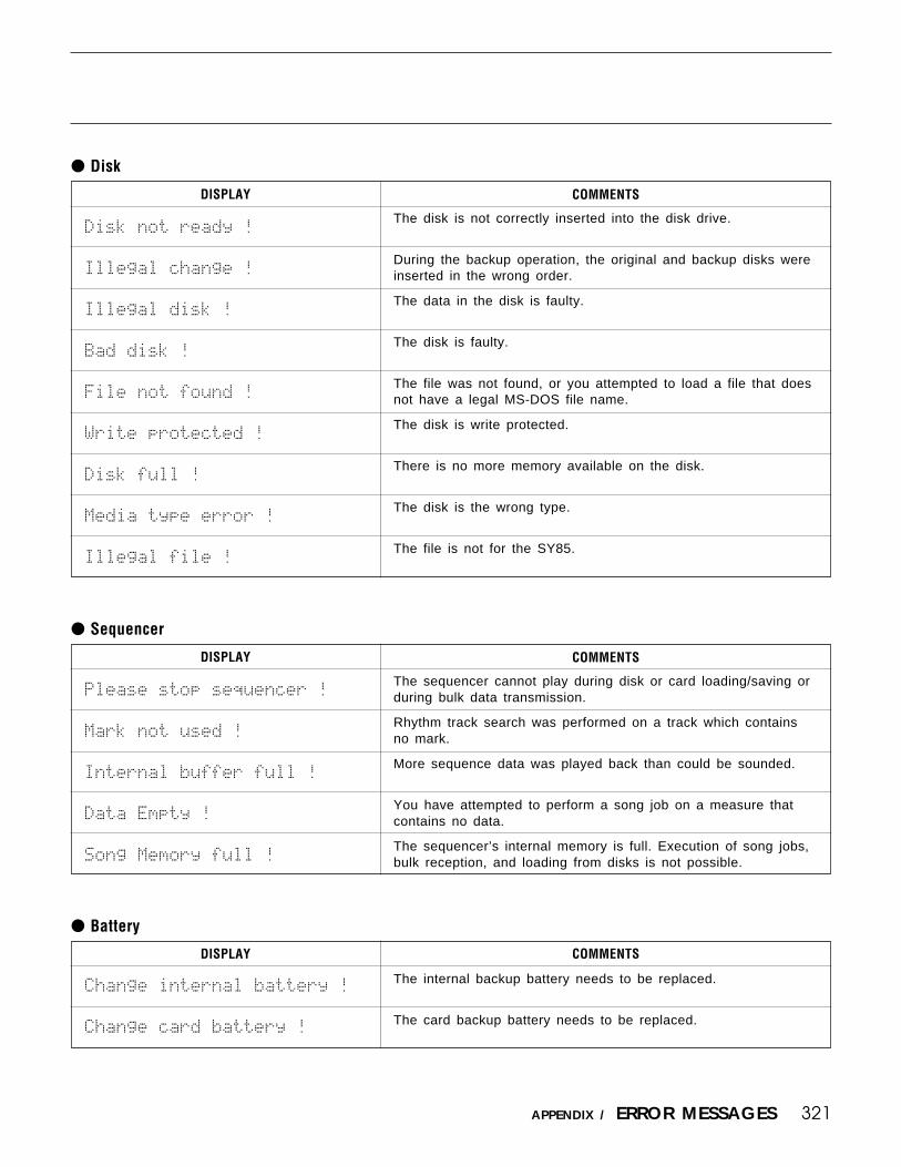
321
Disk
The disk is not correctly inserted into the disk drive.
During the backup operation, the original and backup disks wereinserted in the wrong order.
The data in the disk is faulty.
The disk is faulty.
The file was not found, or you attempted to load a file that doesnot have a legal MS-DOS file name.
The disk is write protected.
There is no more memory available on the disk.
The disk is the wrong type.
The file is not for the SY85.
COMMENTSDISPLAY
Sequencer
The sequencer cannot play during disk or card loading/saving orduring bulk data transmission.
Rhythm track search was performed on a track which containsno mark.
More sequence data was played back than could be sounded.
You have attempted to perform a song job on a measure thatcontains no data.
The sequencer’s internal memory is full. Execution of song jobs,bulk reception, and loading from disks is not possible.
COMMENTS
Battery
DISPLAY COMMENTS
The internal backup battery needs to be replaced.
The card backup battery needs to be replaced.
Change`internal`battery`!
Change`card`battery`!
Disk`not`ready`!
Illegal`change`!
Illegal`disk`!
Bad`disk`!
File`not`found`!
Write`protected`!
Disk`full`!
Media`type`error`!
Illegal`file`!
Please`stop`sequencer`!
Mark`not`used`!
Internal`buffer`full`!
Data`Empty`!
Song`Memory`full`!
DISPLAY
APPENDIX / ERROR MESSAGES
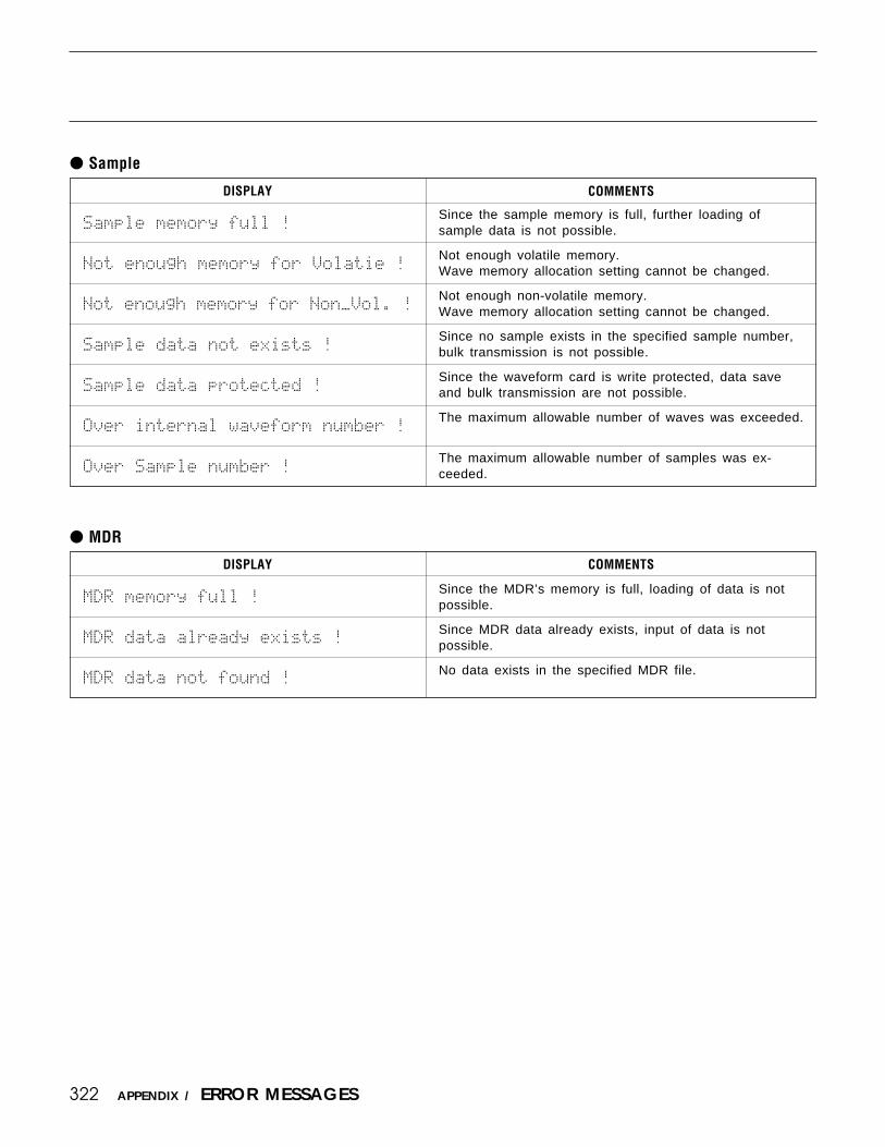
322
Sample
Since the sample memory is full, further loading ofsample data is not possible.
Not enough volatile memory.Wave memory allocation setting cannot be changed.
Not enough non-volatile memory.Wave memory allocation setting cannot be changed.
Since no sample exists in the specified sample number,bulk transmission is not possible.
Since the waveform card is write protected, data saveand bulk transmission are not possible.
The maximum allowable number of waves was exceeded.
The maximum allowable number of samples was ex-ceeded.
COMMENTSDISPLAY
MDR
DISPLAY COMMENTS
Since the MDR’s memory is full, loading of data is notpossible.
Since MDR data already exists, input of data is notpossible.
No data exists in the specified MDR file.
Sample`memory`full`!
Not`enough`memory`for`Volatie`!
Not`enough`memory`for`Non_Vol.`!
Sample`data`not`exists`!
Sample`data`protected`!
Over`internal`waveform`number`!
Over`Sample`number`!
MDR`memory`full`!
MDR`data`already`exists`!
MDR`data`not`found`!
APPENDIX / ERROR MESSAGES

323APPENDIX / ERROR MESSAGES

324
TROUBLE SHOOTING
The SY85 is a very versatile instrument with many features and functions that affect operation. Inmany cases, what appears to be a fault with the SY85 can actually be traced to an improperly set param-eter or, at the most fundamental level, to something as simple as a bad connection.
Here’s how to determine if the problem is internal (e.g. parameter settings) or external (e.g. connec-tions, amplifier, etc.):
Listen Via Headphones.Plug a pair of headphones into the SY85 and play. If the headphone sound is OK, then the problem
is most likely in the amplifier or mixer you are using, or the audio connection cables.
Check the Sound In the Voice, Performance, and Song Modes.If the problem only occurs in one mode or one voice/performance/song, then the cause is most likely
a parameter setting related to that mode or voice/performance/song. If the problem occurs in all modes,then the cause may be a utility parameter or other parameter that affects all modes.
The following are some common problems and probable causes:
Amplifier, Mixer, Connection Problems
Symptom Possible Cause
No Sound
Distorted sound
• Is the amplifier/mixer power turned on?• Is the amplifier/mixer volume set to an appropriate level?• Are the SY85 outputs properly connected to the amplifier/mixer inputs?• Are the connection cables shorted, open, or otherwise faulty?
• Is the SY85 connected to a high-sensitivity microphone or instrument inputon your amplifier or mixer? Try turning the SY85 OUTPUT controls down toavoid overloading the amplifier/mixer inputs.
Performance Mode Problems
Symptom Possible Cause
No Sound
Wrong pitch.
• Are voices properly assigned to the performance layers (page 14)?• Are the voice volume parameters set high enough (page 15)?• Is the total performance level set high enough (page 24)?• Are the voice note and velocity parameters set to appropriate values (page
18 through 21)?• If a foot volume pedal is connected or a controller is assigned to volume
control, is the controller set to produce a high enough volume level (page31)?
• Are the note shift parameters for each voice set to appropriate values(page 17)?.
APPENDIX / TROUBLE SHOOTING

325
Voice Mode Problems
Symptom Possible Cause
No Sound
Wrong pitch.
Unstable/indefinite pitch.
• Is the pitch envelope generator set properly? If the L0 through L3 param-eters are set too low, the resultant pitch may be below the audible range(page 74).
• Is the filter set in such a way that most of the sound is filtered out (page65)?
• Is the total voice level set high enough (page 94)?• Is the amplitude envelope generator attack time set to an excessively long
value (page 60)?• Is an appropriate wave assigned to the voice (page 58)?
• Is the tuning set properly (page 58)?.• Is the note shift parameter set properly (page 59)?.
• Is the random pitch parameter set properly (page 59)?.• Is the aftertouch pitch bias parameter set properly (page 88)?.• Is the LFO pitch modulation parameter set to an excessively high value
(page 78)?.• Is the pitch envelope generator set properly (page 74)?.
Song Mode Problems
Symptom Possible Cause
No Sound
Wrong pitch.
Some notes not played duringsequencer playback.
• Are voices/performance combinations properly assigned to the multi instru-ments (page 148).
• Are the volume levels of the multi instruments set high enough (page 149)?• Are the sequencer track transmit channels properly matched to the multi
instrument channels (Getting Started manual, page 47)?
• Are the note shift parameters for each multi instrument set properly (page152)?.
• Are the tune parameters for each multi instrument set properly (page 153)?.
• Does the sequence data exceed the maximum polyphony of the SY85(page 157)?.
Other Problems
Symptom Possible Cause
No Sound
Wrong pitch.
• Is the local off mode selected (page 211).• Are the keyboard transmit channel and voice receive channels matched
(page 212)?
• Is the master tune parameter set properly (page 210)?.
APPENDIX / TROUBLE SHOOTING

326
INDEX
A
Accent velocity ..................................................... 220Additional MIDI control ..................... 46, 111, 137AEG data copy ....................................................... 64Aftertouch ....................................................... 31, 219Aftertouch depth ..................................................... 87Aftertouch events ................................................. 160Alternate group ..................................................... 122Amplitude EG ......................................................... 98Amplitude EG offset .............................................. 27Amplitude envelope generator .............................. 60Amplitude modulation depth ............ 79, 83, 85, 87Attack mode ............................................................ 60Attack rate .........................................................27, 99Attack rate velocity sensitivity .......................63, 72
B
Bandwidth ................................................................ 67Bank select ............................................................ 215Beat ........................................................................ 217BEF filter response ................................................ 67Blank chart ............................................................ 311BPF filter response ................................................ 67Bulk dump ............................................................. 222
C
Card format ........................................................... 224Card load/save ...................................................... 223Cascade effect parameters ................................... 277Change mode......................................................... 158Clear pattern .......................................................... 203Clear song.............................................................. 179Click condition ..................................................... 217Clock ...................................................................... 217Clock move ........................................................... 195Continuous sliders .................................................. 10Control change events ......................................... 159Control device number ........................................ 175Control LFO .......................................... 47, 138, 176Control parameters ...................... 45, 110, 136, 174Control reset .......................................................... 210Controller ................................................................. 31Controller assignment display .............................. 11
Controller data copy .............................................. 93Copy measure........................................................ 188Copy pattern .......................................................... 202Copy song .............................................................. 180Crescendo .............................................................. 200CS enable ................................................................ 22CS1/CS2 switch ........................... 45, 110, 136, 174CS3 parameter edit ................................................. 89CS4 parameter edit ................................................. 91Cutoff frequency ............................................ 65, 100Cutoff frequency depth ............................. 84, 86, 88Cutoff scaling.......................................................... 69
D
Data entry dial .................................................... 9, 10Decay rate................................................................ 27Delay .......................................47, 79, 112, 138, 176Delete file .............................................................. 231Delete measure ...................................................... 190Delete rhythm track ............................................. 182Delete track ........................................................... 185Device number ...................................................... 212Disk backup........................................................... 232Disk format ........................................................... 235Disk load/save ....................................................... 225Disk status ............................................................. 234Drum key data copy ............................................ 125Drum total level ................................................... 123Drum voice compare ............................................ 145Drum voice edit recall ......................................... 143Drum voice initialize ........................................... 144Drum voice name ................................................. 124Drum voice store .................................................. 146Dry output ............................................. 40, 131, 169Dual effect parameters ......................................... 281
E
Effect 1 parameters ..................... 44, 109, 135, 173Effect 2 mix level ....................... 43, 106, 134, 172Effect 2 parameters ..................... 44, 109, 135, 173Effect configuration ............................................. 254Effect data copy .......................... 48, 113, 139, 177Effect LFO ............................................................ 112Effect mode .................................. 37, 105, 128, 166
APPENDIX / INDEX

327
Effect parameter ...........36, 45, 104, 110, 136, 174Effect send level ................................................... 151Effect signal flow diagrams ....................... 256, 264Effect signal flow display .......... 49, 114, 140, 178Effect source ......................................................... 167Effect type ............................ 35, 37, 103, 105, 126,.............................................................. 128, 154, 166
EG bias depth ............................................ 84, 86, 88EG level & rate ...................................................... 70End of track .......................................................... 158Erase measure ....................................................... 192Error messages ...................................................... 320
F
Filter ....................................................................... 100Filter control ........................................................... 68Filter cutoff frequency ........................................... 30Filter cutoff frequency modulation depth ........... 79Filter data copy....................................................... 73Filter offset .............................................................. 29Filter resonance ...................................................... 30Filter type ....................................................... 65, 100Fine ........................................................................... 58Fine tuning .............................................................. 17Foot controller ........................................................ 31Foot controller depth ............................................. 85Frequency modulation depth .................... 84, 86, 88Function keys .......................................................... 10
G
Gate time ............................................................... 122Gate time modify ................................................. 199
H
High note limit ....................................................... 19High velocity limit ................................................. 21Hold mode ............................................................... 61HPF filter response ................................................ 66
I
Initial drum voice data ........................................ 292Initial multi data ................................................... 300Initial performance data ...................................... 289Initial voice data................................................... 290Insert measure ....................................................... 191Insert mode ............................................................ 161Instrument change ................................................ 204Internal performance list ..................................... 302Internal voice list ................................................. 306
K
Key data exchange ............................................... 142Key data initialize ................................................ 141Key note shift ....................................................... 120Key number .................................................. 120, 122Key on velocity curve ......................................... 216Key pan .................................................................. 121Key parameters ............................................ 120, 122Key scaling .............................................................. 80Key tune ................................................................ 121Key volume ........................................................... 120Key-on velocity sensitivity ................................... 72
L
Layer controller sync ............................................. 50Layer data copy ...................................................... 23Layer exchange ....................................................... 51Layer voice edit menu ........................................... 26Level & rate ............................................................ 74Level scaling ........................................................... 62Level/rate switch .................................................... 70LFO .......................................................................... 78LFO data copy ........................................................ 81LFO depth ...................................................... 29, 102LFO modulation type ........................................... 102LFO offset ............................................................... 29LFO speed ...............................29, 47, 78, 102, 112,....................................................................... 138, 176
LFO waveform .......................47, 78, 112, 138, 176Local on/off ........................................................... 211Loop ....................................................... 75, 221, 246
APPENDIX / INDEX

328 APPENDIX / INDEX
Low and high limits ............................................ 246Low note limit ........................................................ 18Low velocity limit .................................................. 20LPF filter response ................................................. 66
M
Master tuning ........................................................ 210Max. ...................................................................90, 92Maximum parameter value ......... 46, 111, 137, 175MDR ....................................................................... 228Measure dividers .................................................. 158Memory expansion modules ............................... 285Memory installation ............................................. 286Memory status ....................................................... 181Memory type ......................................................... 247Menu key ....................................................................8MIDI control enable ............................................ 218Min. ....................................................................90, 92Minimum foot volume level ................................. 82Minimum parameter value ......... 45, 110, 136, 174Minimum volume level ....................................... 123Mode ........................................................................ 58Mode matrix ...............................................................8Modulation wheel ................................................... 31Modulation wheel depth ........................................ 83Multi Initialize ...................................................... 156
N
Note .......................................................................... 59Note events ............................................................ 159Note limit ................................................................ 18Note shift ...................................... 17, 152, 197, 210
O
Original note ......................................................... 244Oscillator ................................................................. 58Oscillator fix ........................................................... 33Oscillator fix note number .................................... 34Out 1 dry ............................................................... 107Out 1 wet ............................................................... 106Output level .................................. 41, 108, 132, 170
P
Page keys ....................................................................8Pan ................................................................... 16, 150Pattern name.......................................................... 207Pattern number ...................................................... 162Performance compare ............................................. 54Performance edit recall .......................................... 52Performance initialize ............................................ 53Performance name .................................................. 25Performance volume .............................................. 24Performance store ................................................... 55Phase ........................................................................ 79Pitch........................................................................ 245Pitch bend events ................................................. 160Pitch bend range ..................................................... 82Pitch bias depth ...................................................... 88Pitch EG enable ...................................................... 33Pitch EG rate scaling ............................................. 75Pitch EG rate velocity sensitivity ........................ 76Pitch EG velocity sensitivity ................................ 76Pitch EG data copy ................................................ 77Pitch modulation depth ...................... 78, 83, 85, 87Program change events ........................................ 160Program change number ...................................... 215Program change table .......................................... 215Program change type ........................................... 213
Q
Quantize ................................................................. 186
R
Random ..............................................................59, 80Range........................................................................ 76Rate scaling .......................................................63, 71Rates and levels ...................................................... 60Receive channel ........................................... 212, 219Record condition .................................................. 219Release rate .......................................................28, 99Remove event ........................................................ 193Rename file ........................................................... 231Repeats ................................................................... 162Resonance ....................................................... 68, 101

329APPENDIX / INDEX
Reverse ............................................................ 59, 122Rhythm track copy ............................................... 164Rhythm track delete ............................................. 164Rhythm track edit ................................................. 162Rhythm track search ............................................ 165Rhythm track insert .............................................. 163
S
Sample ........................................................... 244, 246Sample data ........................................................... 245Sample dump receive ........................................... 248Sample dump transmit ......................................... 249Sample key map ................................................... 243Sample load/save .................................................. 251Search mark........................................................... 163Send key scaling..................................................... 39Send level .................... 38, 43, 106, 127, 130, 134,.............................................................. 167, 168, 172
Send select ............................................................... 38Send velocity sensitivity .............................. 39, 130Sensitivity ................................................... 63, 72, 76Single effect parameters ...................................... 274Song chain ............................................................. 221Song name ............................................................. 155Specifications ........................................................ 319Speed sensitivity ..................................................... 80Sustain ...................................................................... 33Sustain level ............................................................ 99Sustain switch enable ............................................ 82Switch..................................................... 38, 129, 167System .................................................................... 210System setup data ................................................. 301
T
Tempo change ....................................................... 163Top of track .......................................................... 158Track edit .............................................................. 157Track mixdown ..................................................... 183Transmit channel .................................................. 212Transpose ............................................................... 196Troubleshooting .................................................... 324Tune ................................................................. 17, 153
V
Velocity .................................................................... 80Velocity fix ............................................................. 26Velocity limit .......................................................... 20Velocity modify ........................................... 198, 205Velocity sensitivity.................... 28, 30, 63, 99, 101Velocity sensitivity type ........................................ 72Voice compare ...................................................... 117Voice edit recall ................................................... 115Voice initialize ...................................................... 116Voice name.............................................................. 95Voice number .......................................................... 14Voice select ........................................................... 148Voice store ............................................................ 118Voice volume .......................................................... 94Volume ................................................... 15, 149, 245Volume change ..................................................... 162Volume control device ........................................ 213
W
Wave..........................................................58, 96, 120Wave assign .......................................................... 240Wave card load ..................................................... 250Wave initialize ...................................................... 247Wave list ................................................................ 310Wave memory allocation ..................................... 247Wave memory expansion .................................... 285Wave memory status display .............................. 252Wave mode access ............................................... 238Wave name ............................................................ 240Wave number select ............................................. 239Wet balance .................................. 35, 103, 126, 154Wet:dry balance .................................... 42, 133, 171
[-1] and [+1] keys .............................................. 9, 10

SY04
MIDDLE & SOUTH AMERICAMEXICO
Yamaha De Mexico S.A. De C.V.,Departamento de ventasJavier Rojo Gomez No.1149, Col. Gpe DelMoral, Deleg. Iztapalapa, 09300 Mexico, D.F.Tel: 686-00-33
BRASILYamaha Musical Do Brasil LTDA.Ave. Reboucas 2636, São Paulo, BrasilTel: 55-11 853-1377
PANAMAYamaha De Panama S.A.Edificio Interseco, Calle Elvira Mendez no.10,Piso 3, Oficina #105, Ciudad de Panama, PanamaTel: 507-69-5311
OTHER LATIN AMERICAN COUNTRIESAND CARIBBEAN COUNTRIES
Yamaha Music Latin America Corp.6101 Blue Lagoon Drive, Miami, Florida 33126,U.S.A.Tel: 305-261-4111
EUROPETHE UNITED KINGDOM
Yamaha-Kemble Music (U.K.) Ltd.Sherbourne Drive, Tilbrook, Milton Keynes,MK7 8BL, EnglandTel: 0908-366700
IRELANDDanfay Limited61D, Sallynoggin Road, Dun Laoghaire, Co. DublinTel: 01-2859177
GERMANY/SWITZERLANDYamaha Europa GmbH.Siemensstraße 22-34, D-2084 Rellingen, F.R. ofGermanyTel: 04101-3030
AUSTRIA/HUNGARY/SLOVENIA/ROMANIA/BULGARIA
Yamaha Music Austria Ges mbH.Schleiergasse 20, A-1100 Wien AustriaTel: 0222-60203900
THE NETHERLANDSYamaha Music Benelux B.V.,Verkoop AdministratieKanaalweg 18G, 3526KL, Utrecht, The NetherlandsTel: 030-828411
BELGIUM/LUXEMBOURGYamaha Music Benelux B.V.,Brussels-officeKeiberg Imperiastraat 8, 1930 Zaventem, BelgiumTel: 02-7258220
HEAD OFFICE Yamaha Corporation, Electronic Musical Instrument DivisionNakazawa-cho 10-1, Hamamatsu, Japan 430Tel: 053-460-2445
Die Einzelheiten zu Produkten sind bei Ihrer unten aufgeführtenNiederlassung und bei Yamaha Vertragshändlern in den jeweiligenBestimmungsländern erhältlich.
Para detalles sobre productos, contacte su tienda Yamaha más cercanao el distribuidor autorizado que se lista debajo.
For details of products, please contact your nearest Yamaha or theauthorized distributor listed below.
Pour plus de détails sur les produits, veuillez-vous adresser à Yamahaou au distributeur le plus proche de vous figurant dans la liste suivante.
FRANCEYamaha Musique France,Division Instruments Electroniques et de ScèneBP 70-77312 Marne-la-Valée Cedex 2, FranceTel: 01-64-61-4000
ITALYYamaha Musica Italia S.P.A.,Combo DivisionViale Italia 88, 20020 Lainate (Milano), ItalyTel: 02-935-771
SPAINYamaha-Hazen Electronica Musical, S.A.Jorge Juan 30, 28001, Madrid, SpainTel: 91-577-7270
PORTUGALValentim de Carvalho CI SAEstrada de Porto Salvo, Paço de Arcos 2780 Oeiras,PortugalTel: 01-443-3398/4030/1823
GREECEPhilippe Nakas S.A.Navarinou Street 13, P.Code 10680, Athens, GreeceTel: 01-364-7111
SWEDENYamaha Scandinavia ABJ.A. Wettergrens gata 1, Box 30053, 400 43Göteborg, SwedenTel: 031-496090
DENMARKYS Copenhagen Liaison OfficeFinsensvej 86, DK-2000 Frederiksberg, DenmarkTel: 31-87 30 88
FINLANDFazer Music Inc.Aleksanterinkatu 11, SF 00100 Helsinki, FinlandTel: 0435 011
NORWAYNarud Yamaha ASØsterndalen 29, 1345 ØsteråsTel: 02-24 47 90
ICELANDPáll H. PálssonP.O. Box 85, 121 Reykjavik, IcelandTel: 01-19440
EAST EUROPEAN COUNTRIES(Except HUNGARY)
Yamaha Europa GmbH.Siemensstraße 22-34, D-2084 Rellingen, F.R. ofGermanyTel: 04101-3030
ASIAHONG KONG
Tom Lee Music Co., Ltd.11/F., Silvercord Tower 1, 30 Canton Road,Tsimshatsui, Kowloon, Hong KongTel: 730-1098
INDONESIAPT. Yamaha Music Indonesia(Distributor)PT. NusantikGedung Yamaha Music Center, Jalan Jend. GatotSubroto Kav. 4, Jakarta 12930, IndonesiaTel: 21-520-2577
KOREACosmos Corporation#131-31, Neung-Dong, Sungdong-Ku, SeoulKoreaTel: 02-466-0021~5
MALAYSIAYamaha Music Malaysia, Sdn., Bhd.16-28, Jalan SS 2/72, Petaling Jaya, Selangor,MalaysiaTel: 3-717-8977
PHILIPPINESYupangco Music Corporation339 Gil J. Puyat Avenue, P.O. BOX 885 MCPO,Makati, Metro Manila, PhilippinesTel: 819-7551
SINGAPOREYamaha Music Asia Pte., Ltd.Blk 17A Toa Payoh #01-190 Lorong 7Singapore 1231Tel: 354-0133
TAIWANKung Hsue She Trading Co., Ltd.No. 322, Section 1, FuHsing S. Road,Taipei 106, Taiwan. R.O.C.Tel: 02-709-1266
THAILANDSiam Music Yamaha Co., Ltd.865 Phornprapha Building, Rama I Road,Patumwan, Bangkok 10330, ThailandTel: 2-215-3443
THE PEOPLE’S REPUBLIC OF CHINAAND OTHER ASIAN COUNTRIES
Yamaha Corporation,International Marketing DivisionNakazawa-cho 10-1, Hamamatsu, Japan 430Tel: 053-460-2311
AFRICAYamaha Corporation,International Marketing DivisionNakazawa-cho 10-1, Hamamatsu, Japan 430Tel: 053-460-2311
MIDDLE EASTTURKEY/CYPRUS
Yamaha Musique France, Division ExportBP 70-77312 Marne-la-Valée Cedex 2, FranceTel: 01-64-61-4000
OTHER COUNTRIESYamaha Corporation,International Marketing DivisionNakazawa-cho 10-1, Hamamatsu, Japan 430Tel: 053-460-2311
NORTH AMERICACANADA
Yamaha Canada Music Ltd.135 Milner Avenue, Scarborough, Ontario,M1S 3R1, CanadaTel: 416-298-1311
U.S.A.Yamaha Corporation of America6600 Orangethorpe Ave., Buena Park, Calif. 90620,U.S.A.Tel: 714-522-9011
OCEANIAAUSTRALIA
Yamaha Music Australia Pty. Ltd.17-33 Market Street, South Melbourne, Vic. 3205,AustraliaTel: 3-699-2388
NEW ZEALANDMusic Houses of N.Z. Ltd.146/148 Captain Springs Road, Te Papapa, Auckland,New ZealandTel: 9-634-0099
COUNTRIES AND TRUSTTERRITORIES IN PACIFIC OCEAN
Yamaha Corporation,International Marketing DivisionNakazawa-cho 10-1, Hamamatsu, Japan 430Tel: 053-460-2311
Top Related